


Abstract
Computational limitations of computers have emerged as a critical barrier to the advancement of Computational Fluid Dynamics (CFD). Consequently, exploring novel accelerator architectures tailored for large-scale CFD applications and closely integrated with CFD algorithmic characteristics holds significant value. Through an in-depth analysis of the finite difference method (FDM) for solving Navier–Stokes (N-S) equations, we propose a specialized accelerator architecture for FDM-based CFD (FAcc). Implemented on a 28 nm process, FAcc integrates 16,384 differential computing cores (FCores). Experimental validation demonstrates FAcc’s capability to solve N-S equations of varying complexities by flexibly configuring boundary conditions. Compared to conventional approaches, FAcc achieves significant acceleration performance, with its programmability underscoring adaptability to high-precision, large-scale CFD simulations. As the first CFD-focused accelerator designed from the instruction set architecture (ISA) level, FAcc bridges a critical gap in domain-specific hardware for CFD, offering a paradigm shift in high-performance fluid dynamics computation.
1. Introduction
Computational Fluid Dynamics (CFD) plays a pivotal role in modern engineering, particularly in the aerospace industry, where it is widely applied to aerodynamic optimization [1], turbulence modeling [2], and aircraft design [3]. However, driven by complex geometries, transient flow phenomena, and multiphysics coupling, the growing demand for high-fidelity simulations has exposed significant computational bottlenecks [4]. Traditional CPU-based solvers struggle to balance simulation accuracy with practical time constraints, especially when resolving fine-grained spatiotemporal scales or optimizing designs through iterative parametric studies. This limitation stems fundamentally from the mathematical nature of the Navier–Stokes equations (N-S equations), which lack closed-form analytical solutions for virtually all practical flows. Consequently, CFD inherently relies on approximate computational [5] techniques to transform these continuous partial differential equations into discrete algebraic systems solvable by digital computers. The core challenge lies in the inherent computational intensity of this discretization process, where even moderate-sized meshes require trillions of floating-point operations (FLOPS) per timestep [6]. This approximation paradigm—involving spatial discretization (meshing), temporal discretization, iterative solution methods, and often phenomenological turbulence closures—introduces inherent trade-offs between accuracy, computational cost, and physical scope, necessitating advanced hardware to achieve viable high-fidelity solutions.
Extensive research has been conducted globally to accelerate CFD simulations. With the integration of thousands of cores on a single chip and superior computational capabilities, graphics processing units (GPUs) have become the predominant architecture in high-performance computing (HPC) [7]. Research scopes have expanded from single-GPU implementations to multi-GPU and cluster-based acceleration [8,9,10], encompassing acceleration disparities between explicit and implicit schemes [11,12], distinctions in structured, unstructured, and hybrid grid characteristics [13], computational impacts of single- versus double-precision arithmetic [14,15], and the rising prominence of high-order discretization schemes and high-fidelity methodologies [16,17,18,19,20,21]. For instance, Tutkun et al. [22] demonstrated a 9× to 16.5× speedup over AMD Phenom CPUs by implementing high-order compact finite difference schemes with filtering techniques on Tesla C1060 GPUs for solving compressible Navier–Stokes equations. Similarly, Lei et al. [23] employed second-order MUSCL/NND schemes in Cartesian coordinate systems to accelerate compressible flow solvers, reporting acceleration ratios of 144× for NND and 260× for MUSCL formats using Tesla P100 GPUs compared to a single E5-2640v4 CPU core. NVIDIA has been a key pioneer in driving and leading the development of general-purpose computing on graphics processing units (GPGPU) technology over the past decade. Numerous numerical methods implemented in CFD solvers have been extensively researched and developed based on NVIDIA’s CUDA technology [24,25,26,27]. However, extending existing CFD solvers with CUDA capabilities presents significant challenges. Developers must explicitly define the thread layout (number of blocks, threads per block, etc.) for each kernel function on the GPU, necessitating substantial refactoring of core source code components, which typically demands considerable programming effort. Furthermore, for a production-ready solver, organizations must address both short-term and long-term investment considerations, including costs and returns, alongside platform portability. These factors often deter the adoption of GPU computing for established solution products. As a complementary programming model to CUDA, the OpenACC standard aims to simplify parallel programming for heterogeneous CPU/GPU systems. It enables acceleration by inserting directives into the code to identify regions suitable for parallelization, utilizing OpenACC directives and runtime library routines. This approach avoids the need for significant algorithmic modifications to adapt to specific GPU architectures and compilers. Nevertheless, the current OpenACC specification and its supporting compilers are not yet fully defined and optimized, remaining under active development and refinement [28]. This underscores persistent challenges in achieving high-performance CFD on general-purpose computing hardware, including algorithmic compatibility, parallel efficiency, and memory bandwidth limitations. As emphasized in NASA’s CFD Vision 2030 Study: A Path to Revolutionary Computational Aerodynamics, the evolution of CFD is inextricably linked to innovations in computational platforms [29]. Consequently, future research must prioritize the development of specialized CFD accelerators with novel parallel architectures, guided by numerical models derived from practical applications and tightly integrated with algorithmic characteristics.
The fundamental reliance on approximations within CFD computations highlights the potential of Approximate Computing paradigms to manage the inherent accuracy–cost trade-offs more effectively. Recent research demonstrates promising approaches for hardware-level approximation. Baroughi et al. [30] introduced Approximate and Exact Multi-Processor System-on-Chip (AxE) platform, a heterogeneous RISC-V-based MPSoC (Multi-Processor System-on-Chip) platform integrating both exact and approximate cores, achieving significant speedups (32%) and energy savings (21%) while maintaining high accuracy (99.3%) for suitable workloads. Similarly, Esposito et al. [31] proposed a quality-scalable LMS filter using algorithmic-level approximations introduced by an external quality knob, enabling runtime power savings (5–32%) adaptable to required precision levels. These works exemplify the growing importance of exploiting hardware-aware approximations for computationally intensive domains, providing valuable context for designing specialized accelerators.
Professors Zhuang and Zhang have categorized the research domains of CFD into six branches [32], represented by the acronym M5A, comprising five “M” components and one “A”. The five “M” terms denote Methods, Meshing, Machines, Mapping, and Mechanisms, while “A” signifies Applications. Among these, Method constitutes the cornerstone of CFD research and the most active branch, encompassing diverse numerical approaches such as the finite difference method (FDM), finite volume method (FVM), and finite element method (FEM) [33]. Machine includes computers and supercomputers, which are the hardware resources of CFD. Focusing on the “Methods” and “Machines” aspects, this study leverages the classical FDM as its foundation and proposes a novel reduced instruction set multi-core microprocessor architecture specifically designed to accelerate FDM-based CFD computations. As a classical discretization approach in CFD numerical analysis and simulation, the FDM serves as the foundation of this study. Leveraging the “Methods” paradigm of CFD, this work focuses on computational acceleration for FDM-based solvers and proposes a reduced instruction set multi-core microprocessor architecture dedicated to accelerating CFD computations. The designed accelerator demonstrates network programmability and achieves significant acceleration performance.
The main contributions of this work are as follows.
- Application-Specific Microprocessor Architecture (FCore) and Instruction Set Design. The characteristics of the finite difference method were studied. Based on these characteristics, the FCore microprocessor architecture and its corresponding instruction set architecture (F-RISC) were designed.
- Dedicated Network Structure (FMesh). The FMesh network structure was developed. By equipping each FCore with a dedicated router (FRouter), Fmesh enables the transmission of initial data, boundary condition data, and instruction programs to the FCores, thereby enhancing network programmability.
- High-Performance CFD Accelerator. The proposed FAcc accelerator achieves a significantly higher speedup ratio. It represents the first instruction set architecture-based accelerator specifically designed for CFD.
2. Computational Characteristics of CFD
FDM discretizes the computational domain into a structured grid, replacing continuous solution spaces with a finite set of nodal points [34]. This approach directly transforms differential problems into algebraic systems, enabling approximate numerical solutions through mathematically intuitive and computationally concise formulations. By systematically combining temporal discretization, spatial approximation, and precision criteria, diverse finite difference computational schemes can be constructed to address specific fluid dynamics challenges.
This study investigates the computational characteristics of CFD through the canonical example of a one-dimensional linear convection equation. The governing partial differential equation (PDE) for one-dimensional linear convection is formulated as
Equation (1) is referred to as the governing equation, where u denotes the velocity, t represents time, c is a constant, and x indicates the spatial coordinate direction. To solve Equation (1), a common approach involves its discretization. In this study, the FDM is adopted, employing forward differencing in the temporal domain and backward differencing in the spatial domain. The governing equation is discretized on an equidistant grid within the Cartesian coordinate system, with uniform spacing applied across all computational directions. All relevant variables are stored on a collocated grid architecture. Following the discretization process, the governing Equation (1) can be reformulated as
In Equation (2), n and n + 1 denote two consecutive time steps, while i and i − 1 represent adjacent spatial nodes along the x-coordinate. The velocity update formula derived from Equation (3) is expressed as
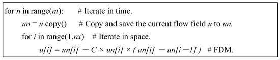
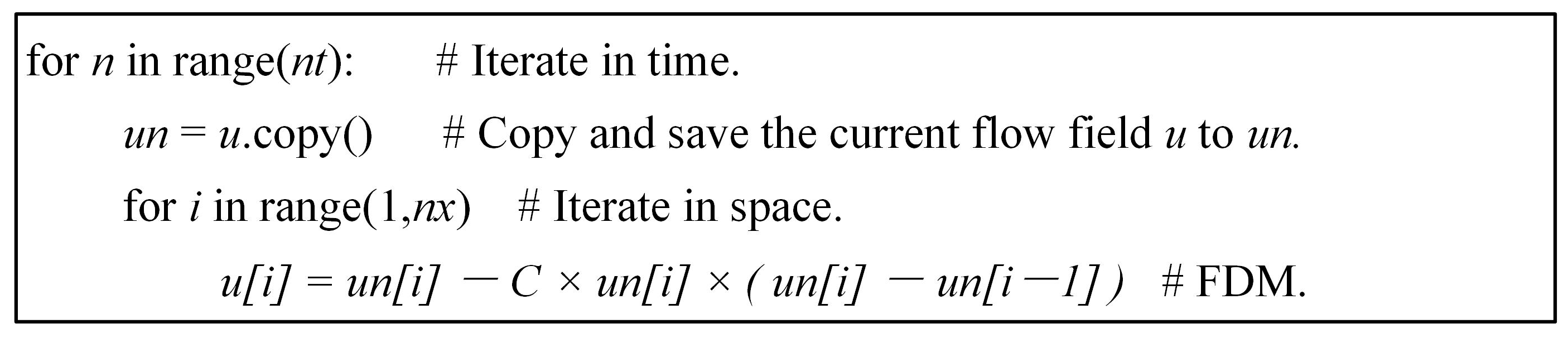
Here, and denote the temporal and spatial discretization step sizes, respectively. The term corresponds to the Courant–Friedrichs–Lewy (CFL) number, denoted as C, which is treated as a predefined constant. Given the initial velocity field at t = 0 (note that boundary conditions are not required for the 1D linear convection equation but may be essential for higher-dimensional systems, e.g., 2D convection), the velocity field at any spatial point and time step can be iteratively computed. The solution procedure for the 1D convection equation involves a time-marching loop, where the velocity field at time n is recurrently updated to n + 1. A pseudocode representation of this iterative process is provided in Figure 1.
Figure 1.
The main pseudo-code of governing 1-D linear convection solving.
As illustrated by the main pseudocode in Figure 1, the CFD algorithm exhibits the following distinctive characteristics:
- Minimal Arithmetic Complexity. Computational operations are limited to basic arithmetic (addition, subtraction, and multiplication).
- High Parallelizability. The absence of control dependencies and structural hazards between spatial nodes enables fully parallel execution. Structural dependencies are resolved by allocating dedicated computational resources to each spatial node.
- Strong Data Locality. Data dependencies are localized to adjacent spatial nodes, with minimal requirements for long-range data exchange across multiple grid points.
- Stable Data Production–Consumption Pattern. Data generated at step n are exclusively consumed at step n + 1, eliminating the need for high-capacity data storage and reducing memory access frequency.
Detailed analysis reveals that these characteristics remain applicable to more complex and higher-order finite difference schemes. In the subsequent sections, we systematically demonstrate how these algorithmic properties are exploited to design a specialized accelerator architecture optimized for CFD.
3. Design and Implementation of Multi-Core Accelerator Architecture
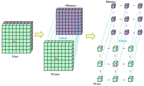
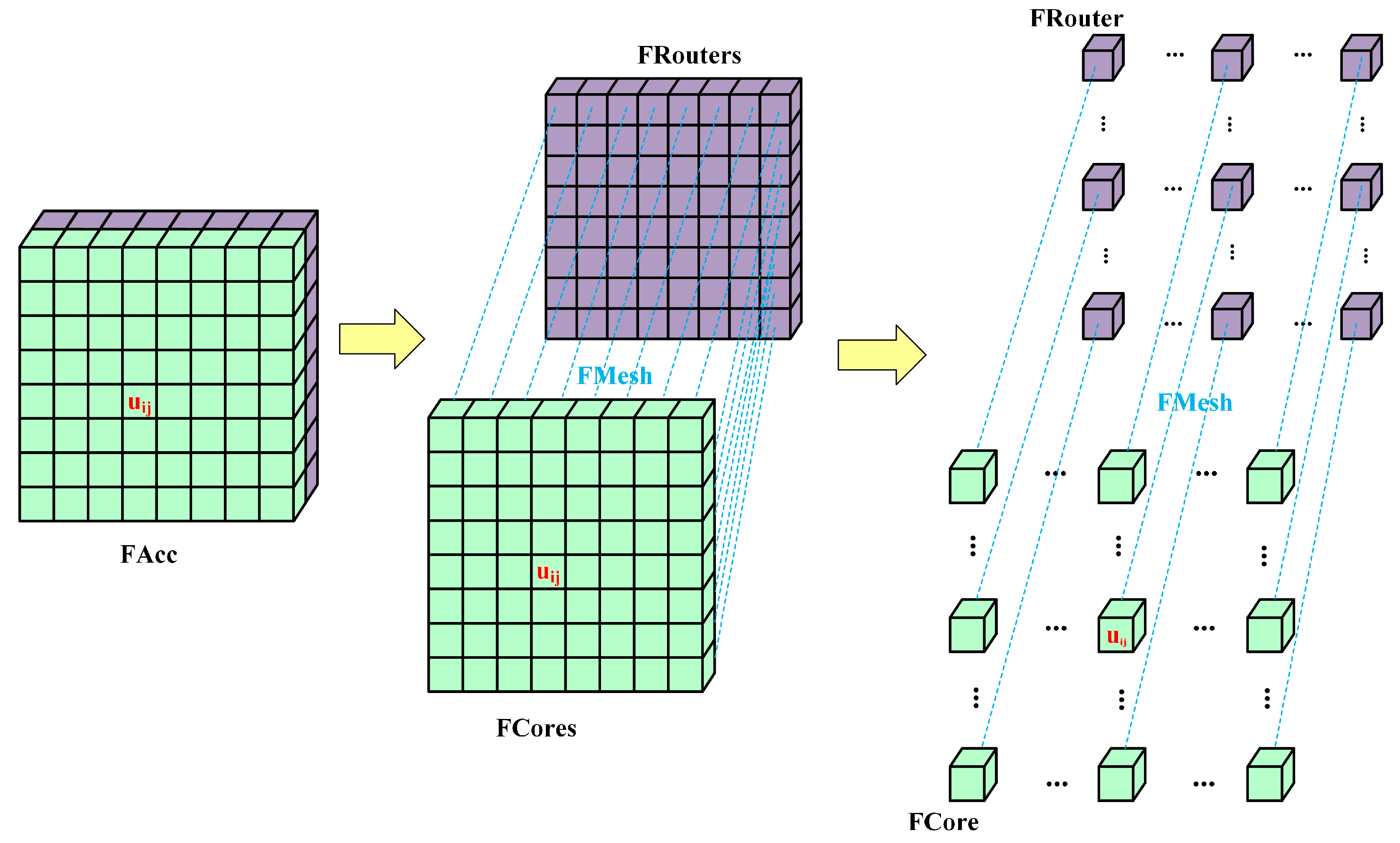
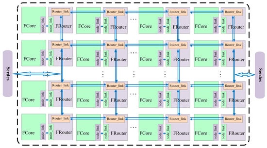
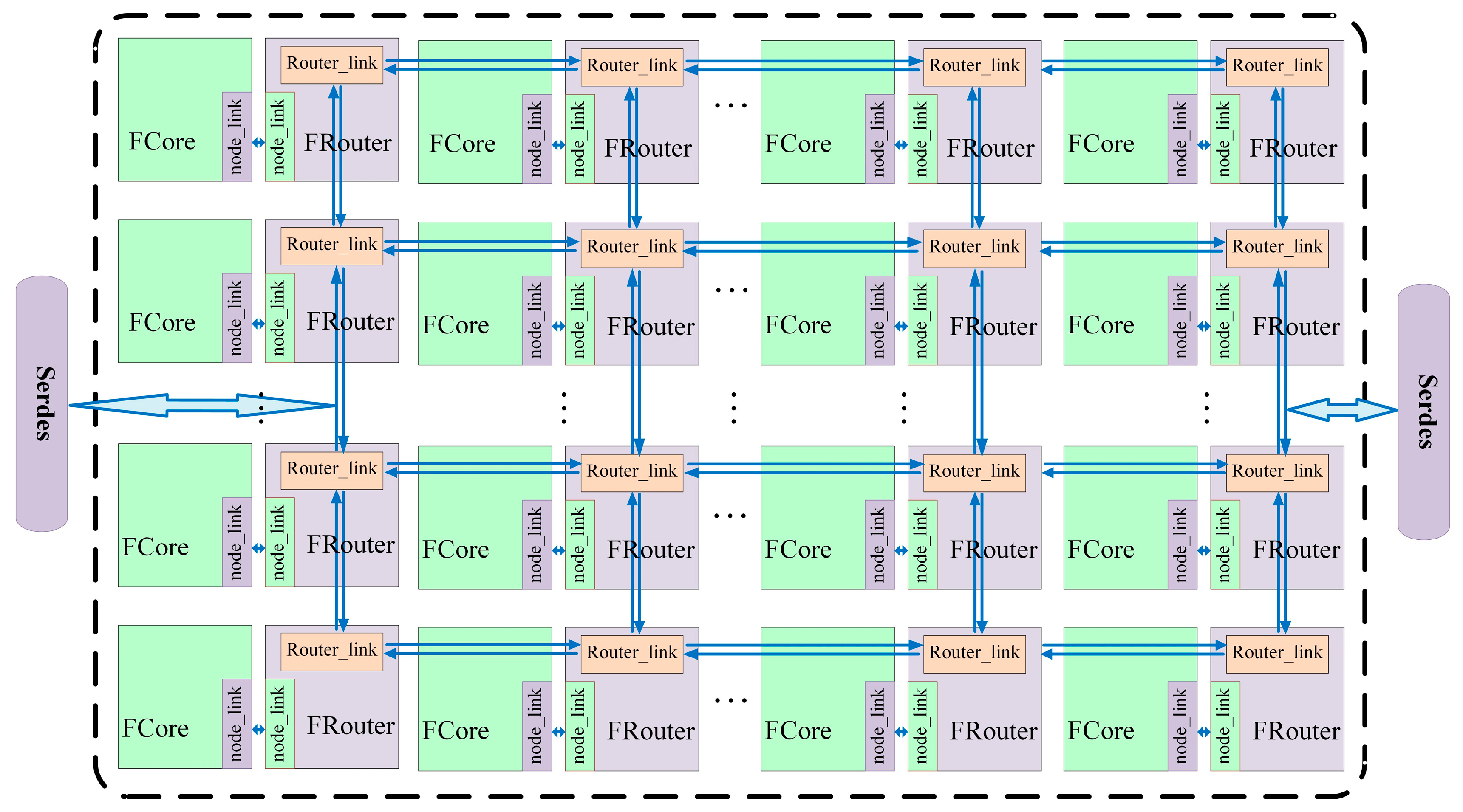
Leveraging the inherent characteristics of the FDM, we implemented a multi-core accelerator microarchitecture for CFD, named FAcc. The FAcc microarchitecture is structured as a two-dimensional matrix of processing cores (FCore), which serve as fundamental computational units. Each FCore is dedicated to executing different operations, with preloaded initial conditions, boundary conditions, and instruction programs required for computation. A dedicated network, called FMesh, manages data delivery (including input parameters and instructions) to FCores and retrieves post-calculation results. Within FMesh, each FCore is interfaced with a router (FRouter) responsible for orchestrating data/instruction routing and result collection. As illustrated in Figure 2, light-green grids represent FCore units, while purple grids denote FRouter components.
Figure 2.
The microarchitecture of the finite difference method accelerator for CFD (FAcc).
3.1. The FCore Implementation
3.1.1. Special ISA Designed
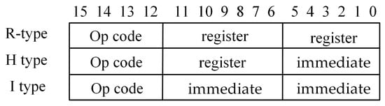
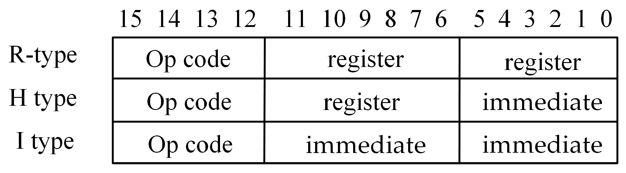
The instruction set architecture (ISA) serves as the interface specification between software and hardware, forming the foundation of information technology ecosystems [35,36,37]. Domain-specific ISAs are tailored to application requirements. In this work, targeting CFD and leveraging the characteristics of the FDM, we designed an ISA supporting looping, branch jumps, floating-point operations, and other critical functionalities. For the FCore processor, we developed a 16-bit domain-specific ISA named F-RISC (CFD-Reduced Instruction Set Computer), as depicted in Figure 3. The instruction format follows a three-address structure, comprising a 4-bit opcode and two 6-bit operands (operand_1 and operand_2). Based on operand types, instructions are categorized into three classes.
Figure 3.
16-bit special instruction set.
- Register-type (R-type). Both operands sourced from registers. Processor Usage: Operands are retrieved exclusively from the register file. The instruction’s opcode triggers ALU computation using two register-addressed values, with results written back to a destination register.
- Immediate-type (I-type). Both operands are immediate values. Processor Usage: Embeds operands directly within the instruction word. During decode, immediate values are sign-/zero-extended and propagated to the ALU or memory interface, bypassing register fetch.
- Hybrid-type (H-type). One operand is sourced from a register, while the other is an immediate value. Processor Usage: Combines one register-sourced operand with an instruction-embedded immediate. The register operand accesses the register file, while the immediate is concurrently expanded and routed to the execution unit.
The F-RISC instruction set comprises fourteen machine instructions, as detailed in Table 1, including six computational instructions supporting fixed-point addition/subtraction, floating-point addition/subtraction/multiplication, and fixed-point comparison; seven control instructions enabling conditional branching and jump operations for loop implementation; and one data movement instruction for register-to-register or memory-to-register transfers. This streamlined design minimizes instruction length and reduces decoding overhead, aligning with the efficiency requirements of CFD-specific hardware acceleration.
Table 1.
Instruction listing for CFD-Reduced Instruction Set Computer (F-RISC).
3.1.2. FCore, Four-Stage Pipeline Microprocessor
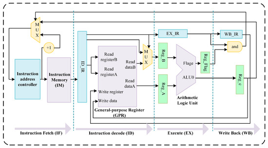
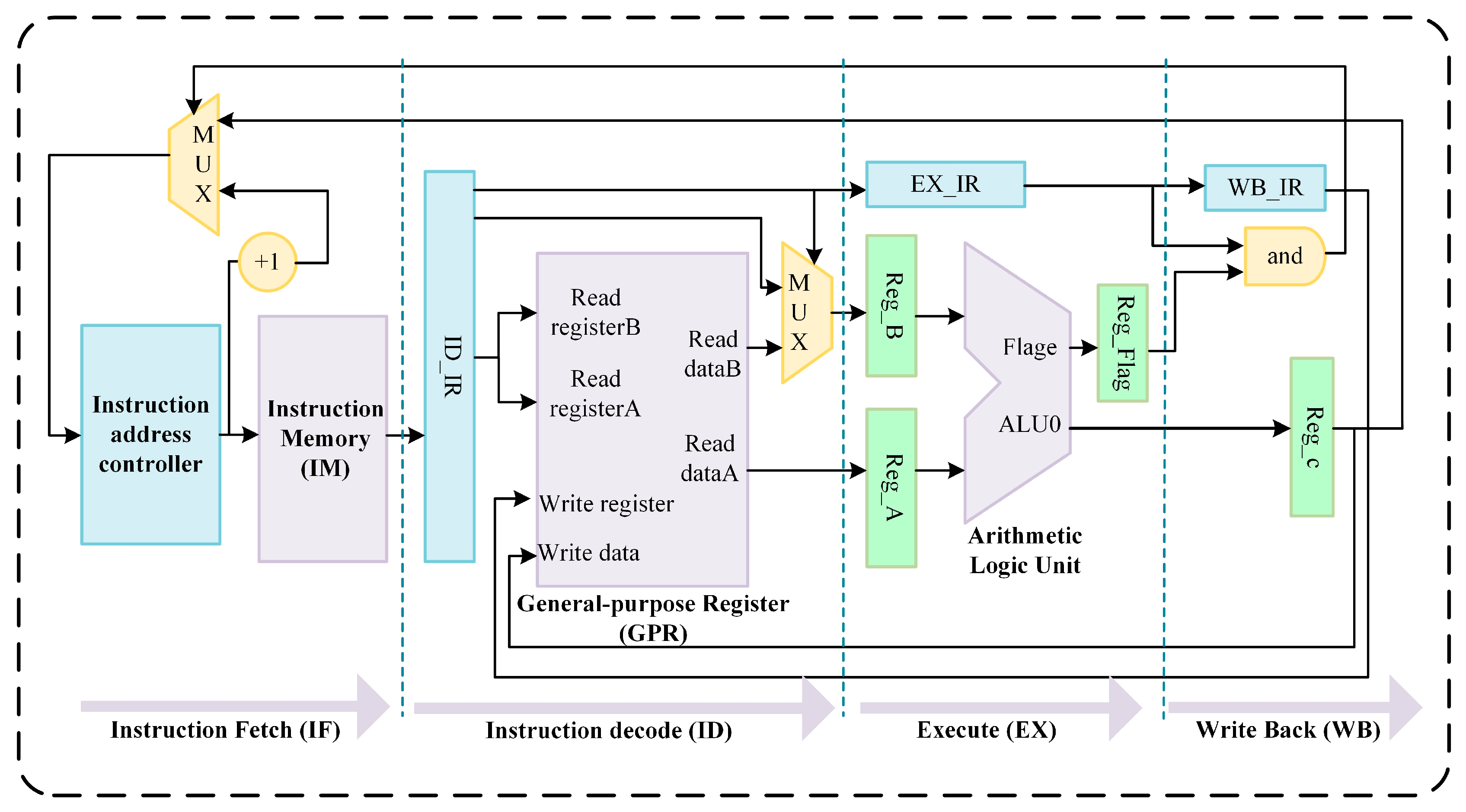
The designed microprocessor architecture for CFD, termed FCore, is structured as a four-stage pipeline, as illustrated in Figure 4. The pipeline stages are defined as follows:
Figure 4.
The microarchitecture of FCore.
- Instruction Fetch (IF) Stage: This stage incorporates a 128-depth instruction memory (IM) and addressing logic. It fetches the current instruction based on the value of the instruction address controller and determines the next instruction address for the subsequent clock cycle, supporting both sequential execution and branch/jump operations.
- Instruction Decode (ID) Stage: Equipped with a 60-entry general-purpose register (GPR) file, this stage decodes the instruction retrieved from the IF stage by interpreting its opcode and operand fields.
- Execute (EX) Stage: The arithmetic logic unit (ALU) performs operations such as fixed/floating-point addition, subtraction, multiplication, comparison, and branch target address calculation.
- Write Back (WB) Stage: This final stage updates the GPR file with computational results generated in the EX-stage.
The FCore architecture intentionally omits techniques such as branch prediction, out-of-order execution, and multi-level memory hierarchy. While these features generally enhance performance in conventional processors, they provide marginal benefits for FDM-specific computations. Instead, they introduce unnecessary control logic complexity and resource overhead, which constrain the scalability of integrated core arrays. The capacity of the GPR file and IM serves as critical design parameters in the FCore architecture, directly determining its ability to support a broad range of FDM-based programs. Through extensive algorithmic analysis and a design philosophy optimized to minimize logic complexity while maintaining support for finite difference computations, the GPR and IM capacities were determined as 60 entries and 128 instructions, respectively. Experimental validation in Section 4 demonstrates that this configuration suffices for solving complex N-S equations.
3.2. FMesh, the Bridge of FAcc Communicatio
Prior to FCore execution, the instruction programs must be preloaded into the IM, while initial conditions and boundary conditions required for finite difference operations are loaded into the GPRs. Upon the completion of FCore computations, the results must be retrieved. To address these requirements, we designed FMesh, a two-dimensional on-chip mesh network tailored to the computational characteristics of finite difference methods. FMesh facilitates the delivery of initial state data, boundary condition parameters, and instruction programs to FCores, as well as the collection of computational results. As illustrated in Figure 5, FMesh operates as a hierarchical data-routing infrastructure, ensuring deterministic data provisioning and result aggregation across the FCore array.
Figure 5.
The FMesh architecture.
3.2.1. The FRouter Implementation
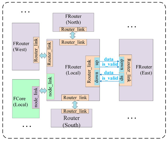
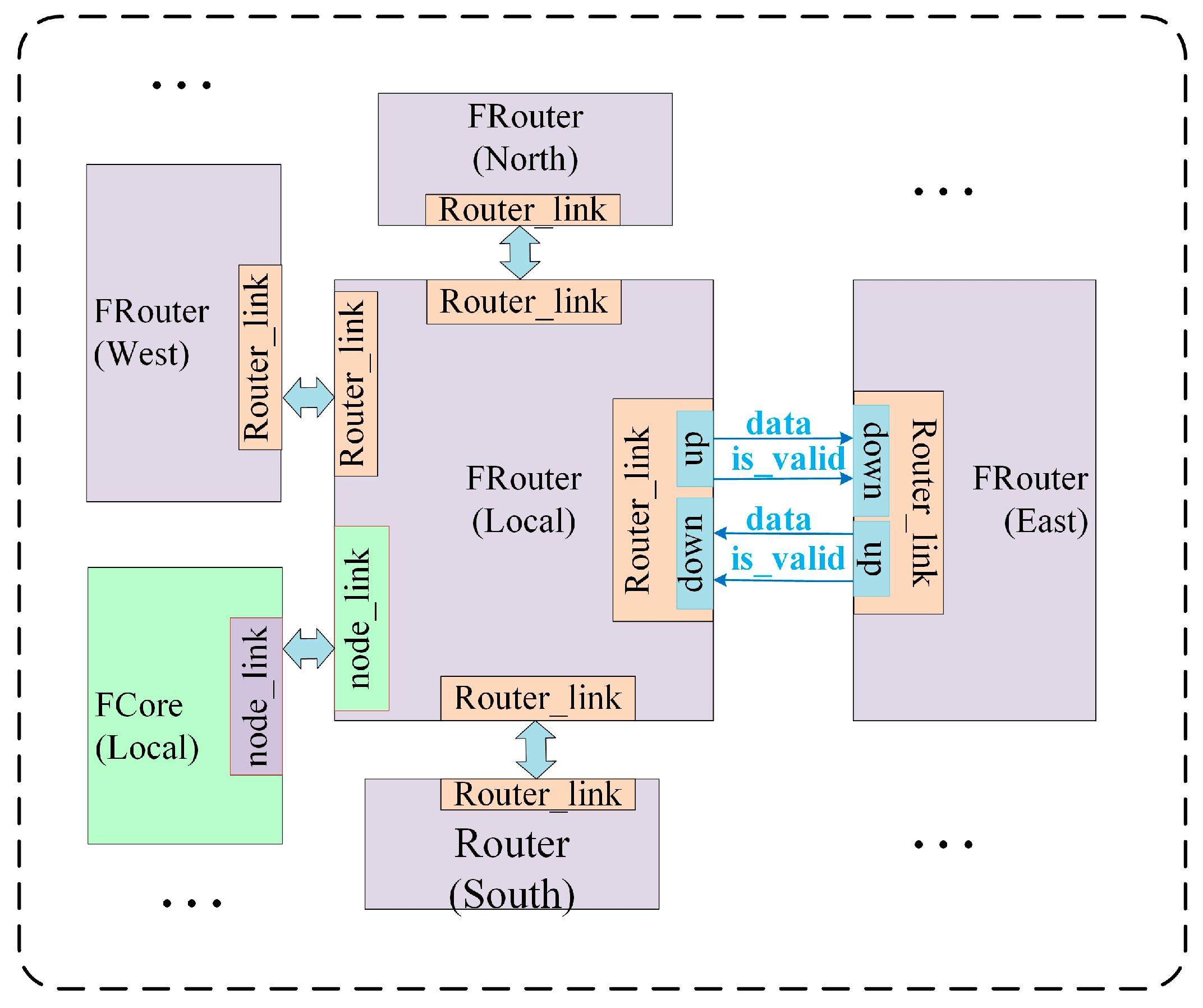
Within the FMesh network, each FCore is interfaced with a dedicated router named FRouter. Figure 6 illustrates the port design of FRouter, where the data port transmits flow control units from upstream to downstream routers, and the is_valid signal indicates whether the incoming flit is valid for the downstream FRouter.
Figure 6.
The port design of FRouter.
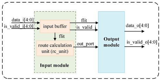
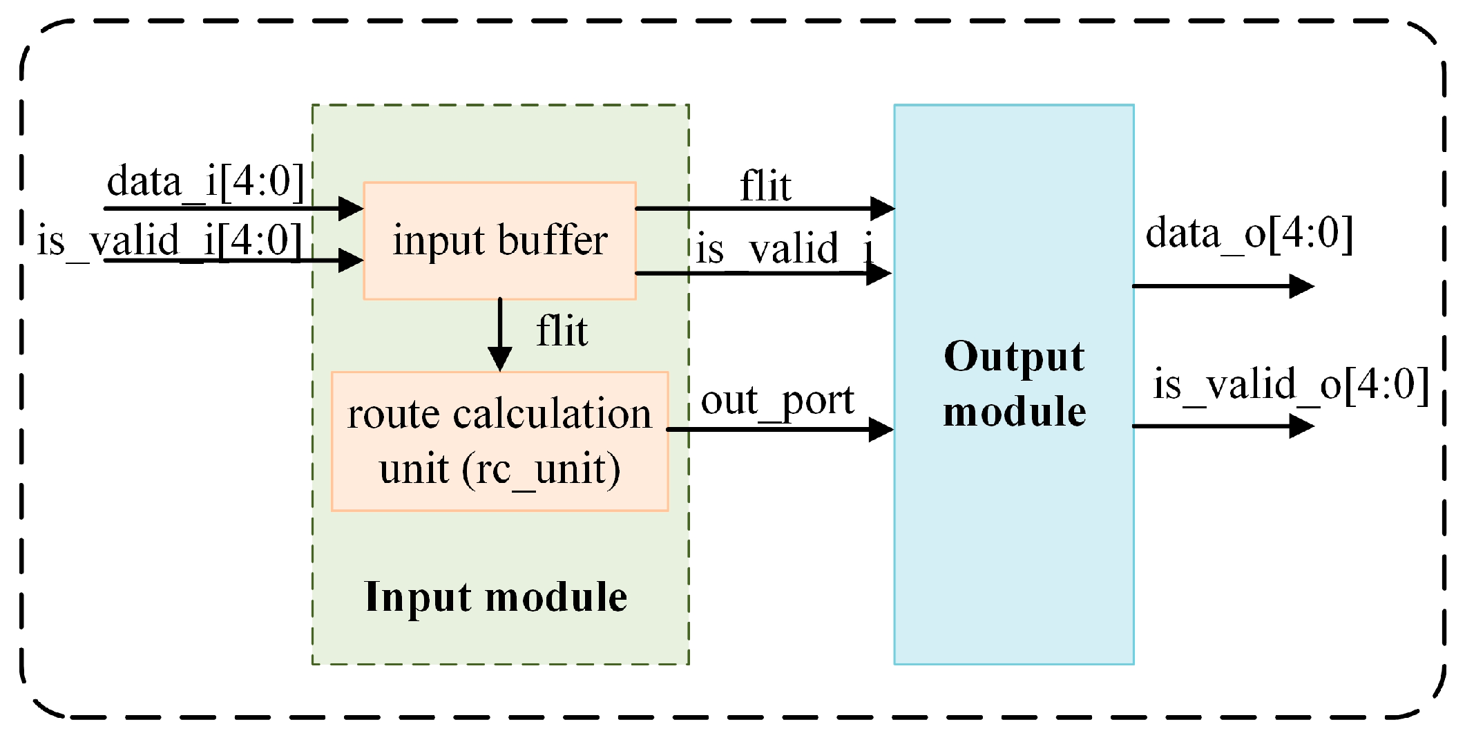
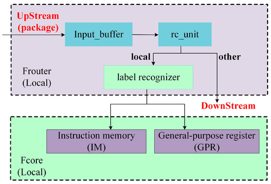
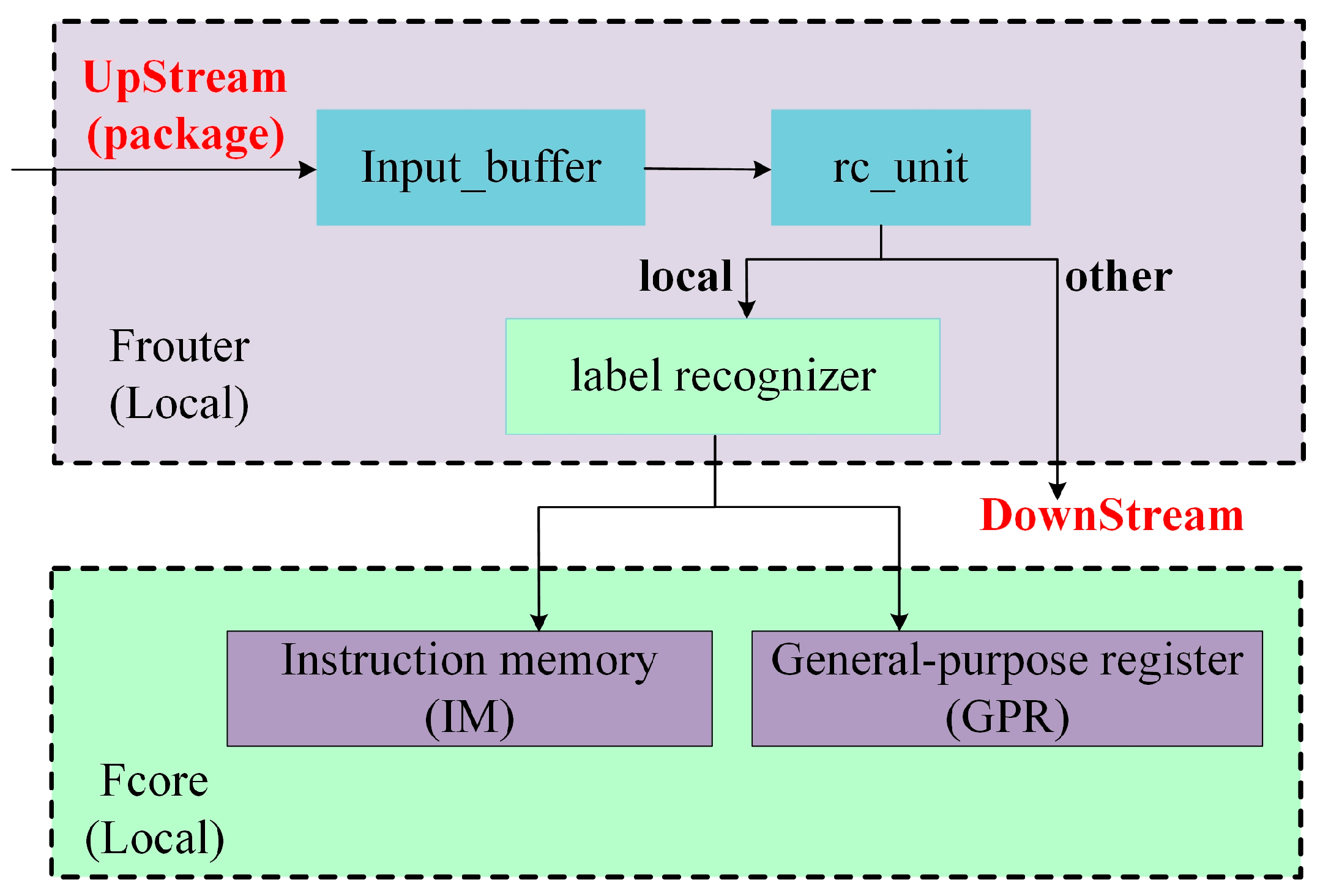
The FRouter architecture employs a minimalist design comprising two modules: Input module and Output module. As depicted in Figure 7, the Input module integrates an input buffer and a routing computation unit (rc_unit). The FRouter receives data from five directional ports (north, south, east, west, and local), storing incoming flits in the input buffer. Valid flits are identified via the is_valid signal, then forwarded to both the rc_unit and Output module. The rc_unit computes the output port direction based on predefined routing policies, while the Output module transmits data according to these computed directions. To simplify the design and minimize input buffer depth, each FRouter processes valid data from only one active port per cycle, determined by the is_valid signal. If multiple valid ports are detected, data transmission follows a prioritized sequence of west → north → east → south. When the computed out_port is designated as local, the flit is further classified as either an instruction (routed to the instruction memory, IM) or data (routed to the general-purpose register file, GPR).
Figure 7.
The structure of FRouter.
3.2.2. Package and Flits Design Scheme
This work defines five types of flits, categorized as head–body flits (Type 1–4) and body-only flits (Type 5), as detailed in Table 2. These flits orchestrate the transmission of instruction programs and computational data to the IM and GPR of each FCore. Each data package requires a minimum of two flits, with transmission governed by four distinct scenarios.
Table 2.
The type of flit.
- Type 1 followed by one or more Type 5 flits.
- Type 2 followed by one or more Type 5 flits.
- Type 3 followed by one or more Type 5 flits.
- Type 4 followed by one or more Type 5 flits.
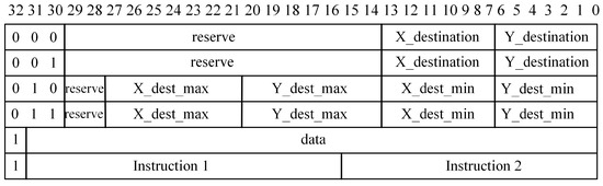
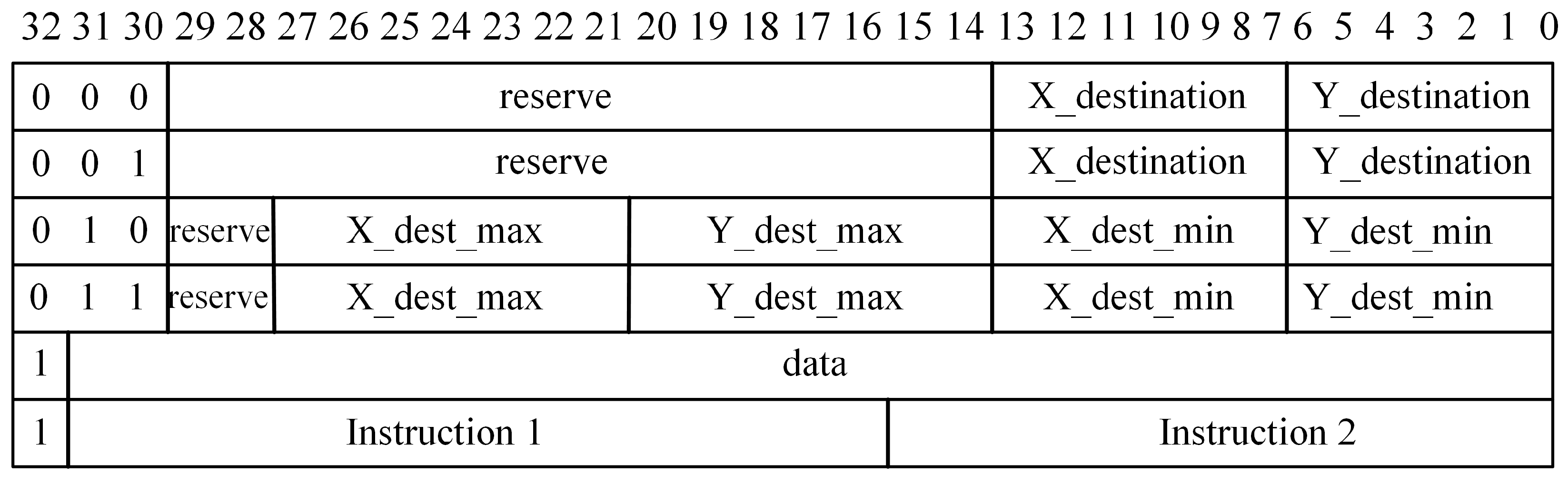
The channel width is designed as 33 bits, with Figure 8 illustrating the flit encoding scheme. The two most significant bits (MSBs) dictate the transmission mode:
Figure 8.
The encoding method of Flit.
- MSBs = 00, unicast to a specific FCore at coordinates (X_destination, Y_destination).
- MSBs = 01, region-based broadcast to all FCores with X ≤ X_destination_max and Y ≤ Y_destination_max.
- MSB = 1, direct transmission of data or instructions to targeted FCores.
Notably, the IM operates on a 16-bit architecture. During instruction transmission, a single 33-bit flit encapsulates two 16-bit instructions, optimizing bandwidth utilization while maintaining compatibility with the FCore’s instruction pipeline.
3.3. FAcc Working Modes
To support inter-core data transfer and finite difference computations, the FAcc architecture operates in three distinct modes: Loading Mode, Calculating Mode, and Recycle Mode. The FMesh network manages data loading (Loading Mode) and result retrieval (Recycle Mode), while finite difference calculations are executed within FCores during Calculating Mode.
3.3.1. Loading Mode
The Loading Mode initializes each FCore by transferring instruction programs, initial conditions, and boundary conditions from off-chip storage to on-chip FCores via the FMesh network. During this phase, FCores suspend computations and inter-core data transfers. Data and instructions propagate unidirectionally from designated edge nodes to the entire chip, with no output generated. This mode enables flexible configuration of boundary and initial conditions, enhancing network programmability.
Key operational principles are as follows.
- Unidirectional Propagation: Data injected into FMesh flows away from the input port, ensuring each FRouter receives valid data from only one port per cycle. This eliminates overhead arbitration caused by concurrent valid data arrivals at a single FRouter, thereby significantly simplifying FRouter design.
- Local Routing Logic: As illustrated in Figure 9, upon receiving a data packet, the local FRouter’s routing computation unit (rc_unit) parses and forwards it to downstream FRouters. A tag decoder determines whether the packet targets the local FCore, subsequently routing it to either the IM or GPR.
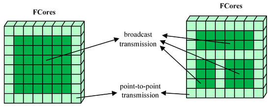
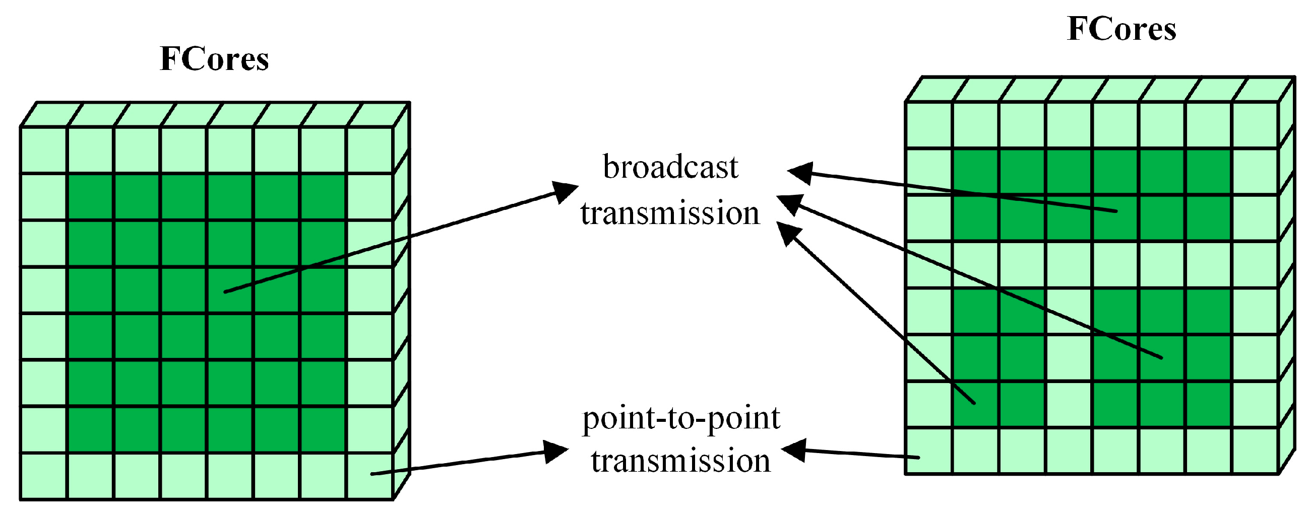
- Hybrid Transmission Strategies: To minimize packet size and optimize transmission efficiency, FMesh supports broadcast and point-to-point modes. Identical instruction programs are broadcast to all FCores, while initial/boundary conditions employ hybrid transmission: broadcast for shared data (dark green FCores in Figure 10) and point-to-point for unique data (light green FCores in Figure 10).
Figure 9.
Data flow direction in loading mode.
Figure 10.
Examples of transmission strategies.
3.3.2. Calculating Mode
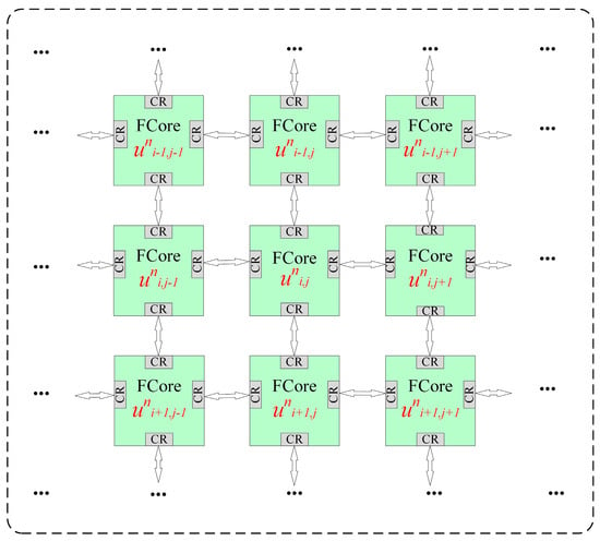
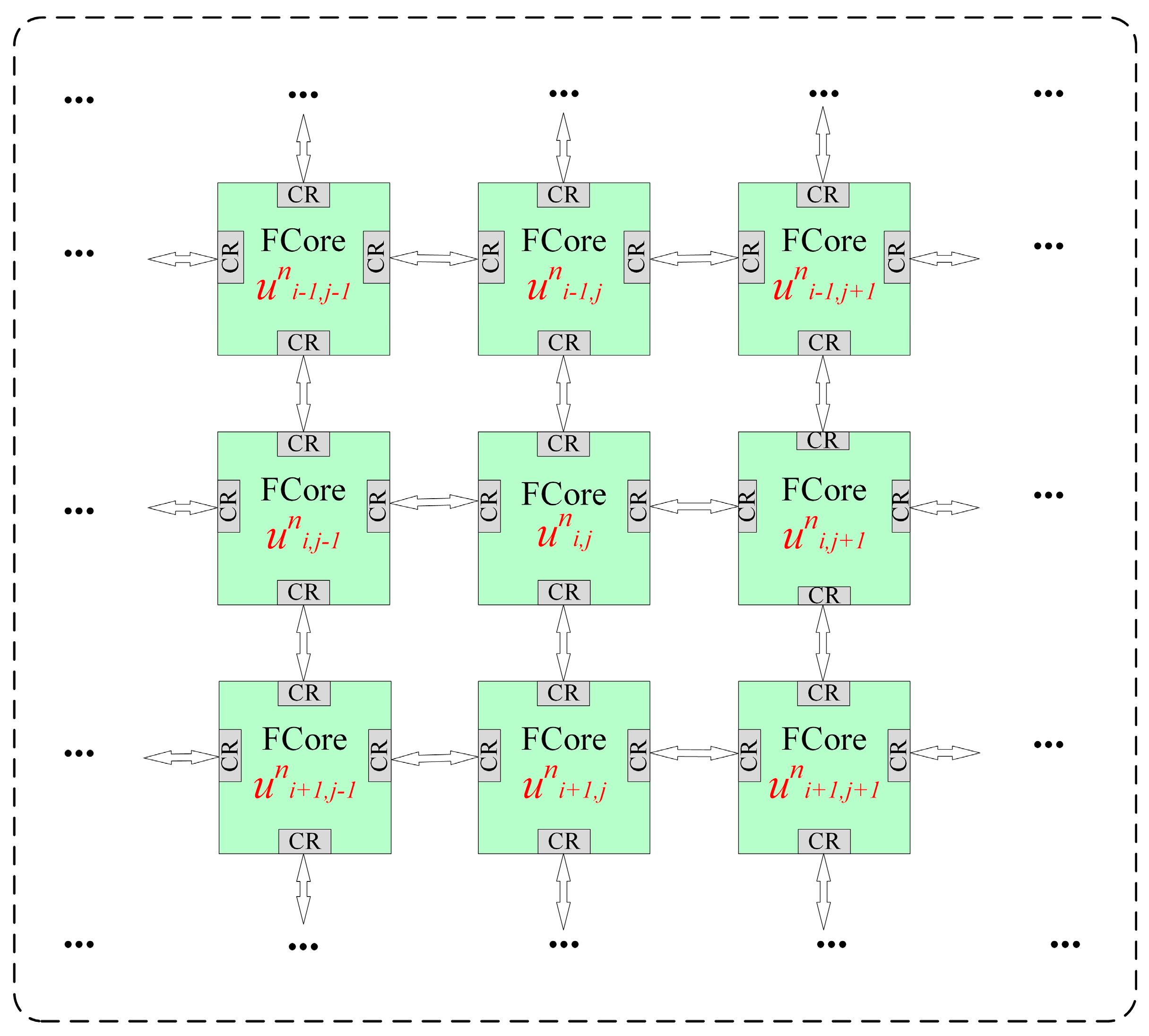
Following the completion of the Loading Mode, the system transitions to Calculating Mode, where data exchange occurs exclusively between FCores. Since inter-FCore communication is mediated through a global shared buffer, all data transfers must first be routed to global data storage. However, global memory exhibits the highest latency among memory hierarchies, requiring significant time for data transmission and retrieval. To mitigate this latency, each FCore is equipped with four communication registers (CRs) positioned at its four boundaries, as illustrated in Figure 11. These CRs enable nearest-neighbor data communication, allowing FCores to bypass the global buffer for local data exchanges. Each FCore corresponds to a spatial array in the CFD simulation, which is maximized to resolve resource dependency conflicts and enhance parallelism. To achieve such array scaling, the architecture minimizes control logic overhead while proportionally increasing computational resources, maintaining essential programmability.
Figure 11.
The method of communication between FCore to Fcore.
3.3.3. Recycle Mode
Upon computation completion, FAcc transitions to Recycle Mode, transferring state data from each FCore to edge nodes for off-chip transmission via SerDes interfaces. Data is routed point-to-point, with transmission requests prioritized as local → east → south → west → north.
3.4. Physical Design Implementation
The RTL-level design of FCore and FMesh was coded in Verilog. Subsequent synthesis and physical implementation employed industry-standard electronic design automation (EDA) tools with 28 nm process node to evaluate performance and area overhead. These EDA workflows were executed on an Intel® Xeon® Gold 6140 CPU workstation operating at 2.30 GHz.
Post-layout characterization of the FCore demonstrates a compact area of 144 × 144 μm2 with 90% utilization density, achieving an operating frequency of 1.25 GHz under worst-case conditions (SS corner, 0.81 V, 125 °C, RC_worst). Power consumption was analyzed using dedicated EDA tools through industry-standard static power analysis methodology. At a switching activity of α = 0.2, the measured power was 24.9 mW. Port placement was strategically optimized based on dataflow requirements, aligning north, south, east, and west communication registers (CRs) with adjacent FCores to ensure seamless interconnection. The FAcc architecture integrates 16,384 (128 × 128) FCores in a seamless matrix configuration. The total chip area measures 20.5 × 20.5 mm2, delivering a power consumption of 410 W and an energy efficiency of 99.9 GFLOPS/W.
4. Performance and Discussion
4.1. In the Calculating Mode
The overhead metrics for the computational mode are summarized in Table 3. We evaluated six N-S equations with varying computational complexities. The results indicate that the maximum number of instruction programs required is 111 instructions, the peak utilization of GPRs reaches 41 registers, and the network scale (the number of active FCores) is determined by the governing equations, peaking at 81 × 81 FCores in this experiment.
Table 3.
Calculation mode overhead.
Given that the FAcc architecture provides an IM capacity of 128 instructions and a GPRs capacity of 60 registers, alongside a scalable network configuration of 128 × 128 FCores, the system demonstrates sufficient resources to efficiently support most finite-difference-based CFD equation-solving tasks.
4.2. In the Loading and Recycle Mode
Table 4 presents the overhead resource for Loading and Recycle Modes when solving six distinct N-S equations. The network scale (i.e., FCores count) determines both network dimensions (e.g., 81 × 81 FCores) and cycle duration, whereas the number of flits and loading duration depend on multiple factors, including network scale, initial data volume, and boundary condition distribution. Similarly, the Recycle Mode duration is linearly correlated with the network scale (i.e., the total number of FCores).
Table 4.
Loading and Recycle Mode overhead.
These results validate that the resource overhead for both modes scales predictably with problem complexity, demonstrating the architecture’s adaptability to diverse CFD workloads.
4.3. Overall Performance
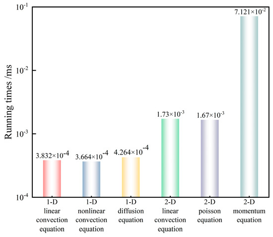
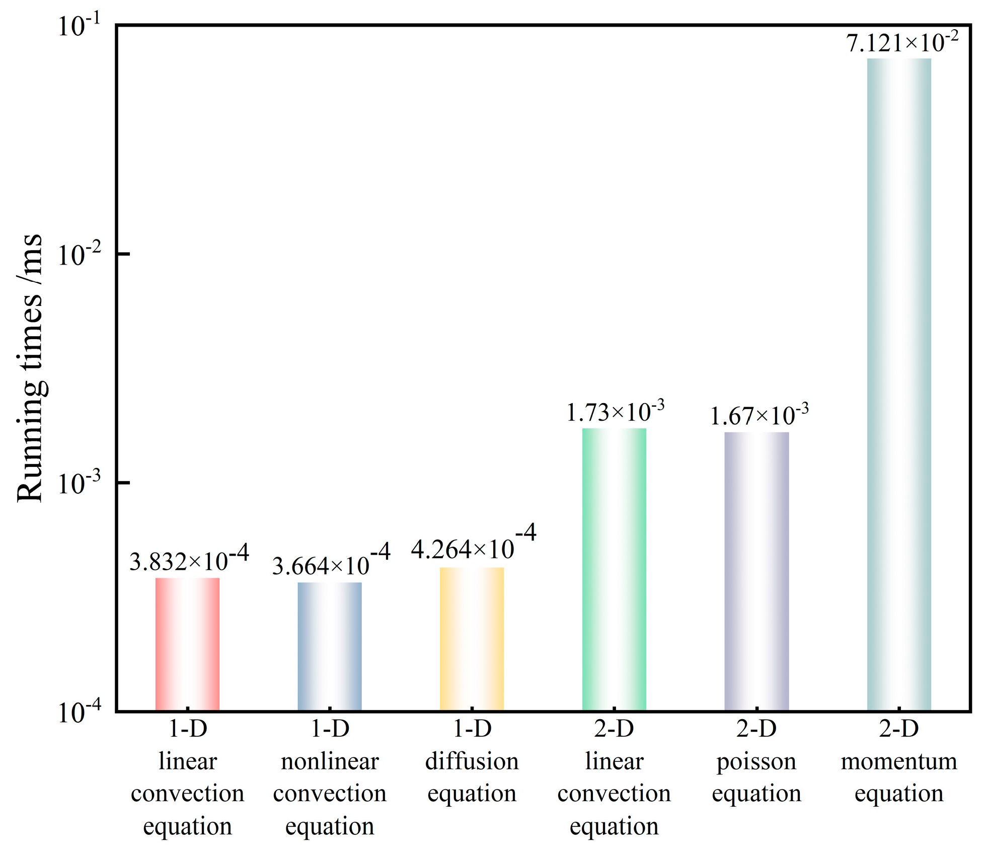
We evaluated the FAcc system by measuring its execution times for solving various governing equations. Under WC corner conditions, FAcc achieved a maximum operating frequency of 1.25 GHz. Figure 12 illustrates the total execution time of FAcc for solving various governing equations, including data loading, calculating, and result recycling phases. The results demonstrate remarkably low execution times, 3.832 × 10⁻⁴ ms for the simple 1D linear convection equation and 0.07121 ms for the complex 2D momentum equation. Benchmarking against the accelerator reported in Reference [23], FAcc achieves 6.8× and 7.7× speedup factors over the conventional MUSCL and NND schemes, respectively.
Figure 12.
The running time under different governing equations.
5. Conclusions
In this work, we analyze the current computational challenges in CFD and propose the FAcc architecture, a novel accelerator tailored to FDM-based CFD algorithms. The FAcc architecture integrates FCore, a RISC-based microprocessor optimized for nodal difference operations in flow fields, and FMesh, a network structure supporting deterministic data loading and recycling. To our knowledge, this is the first accelerator explicitly designed for CFD from the ISA level, addressing a gap in the existing literature. The RTL-level design of FAcc was synthesized and implemented using a 28 nm process, achieving a full-chip integration of 16,384 FCores. Experimental validation involved solving six N-S equations of varying complexity, demonstrating the architecture’s functional completeness and network programmability. FAcc demonstrates significant acceleration performance, achieving speedup factors of 6.8× and 7.7× compared to conventional MUSCL and NND schemes, respectively.
This study focuses exclusively on finite difference methods for CFD. While the designed, dedicated CFD accelerator demonstrates certain limitations, future work will incorporate more CFD methodologies (e.g., FVM) and expand comparisons with advanced HPC systems, such as Grace Blackwell desktop HPCs. Furthermore, algorithmic-level optimizations will be implemented (e.g., reducing loop execution time through double-step Jacobi iteration) to balance hardware overhead against computational performance.
Author Contributions
Conceptualization, Y.G. and B.L.; methodology, Y.G., W.L. and B.L.; software, D.H.; validation, Y.G., W.L. and X.W.; formal analysis, Y.G.; investigation, Y.G.; resources, B.L.; data curation, Y.G. and X.W.; writing—original draft preparation, Y.G.; writing—review and editing, B.L.; visualization, Y.G.; supervision, B.L.; project administration, D.H.; funding acquisition, B.L. All authors have read and agreed to the published version of the manuscript.
Funding
This research received no external funding.
Institutional Review Board Statement
Not applicable.
Informed Consent Statement
Not applicable.
Data Availability Statement
The data presented in this study are available on request from corresponding authors.
Acknowledgments
The authors acknowledge support from the Key Laboratory of Experimental Environment, National University of Defense Technology.
Conflicts of Interest
The authors declare no conflicts of interest.
References
- Koziel, S.; Tesfahunegn, Y.; Leifsson, L. Variable-Fidelity CFD Models and Co-Kriging for Expedited Multi-Objective Aerodynamic Design Optimization. Eng. Comput. 2016, 33, 2320–2338. [Google Scholar] [CrossRef] [Scilit]
- Posch, S.; Gößnitzer, C.; Lang, M.; Novella, R.; Steiner, H.; Wimmer, A. Turbulent Combustion Modeling for Internal Combustion Engine CFD: A Review. Prog. Energy Combust. Sci. 2025, 106, 101200. [Google Scholar] [CrossRef] [Scilit]
- Viviani, A.; Aprovitola, A.; Pezzella, G.; Rainone, C. CFD Design Capabilities for next Generation High-Speed Aircraft. Acta Astronaut. 2021, 178, 143–158. [Google Scholar] [CrossRef] [Scilit]
- Zhang, L.; Deng, X.; He, L.; Li, M.; He, X. The Opportunity and Grand Challenges in Computational Fluid Dynamics by Exascale Computing. Acta Aerodyn. Sin. 2016, 34, 405–417. [Google Scholar]
- Liu, W.; Lombardi, F.; Shulte, M. A Retrospective and Prospective View of Approximate Computing. Proc. IEEE 2020, 108, 394–399. [Google Scholar] [CrossRef] [Scilit]
- Borges, R.B.D.R.; Da Silva, N.D.P.; Gomes, F.A.A.; Shu, C.-W. High-Resolution Viscous Terms Discretization and ILW Solid Wall Boundary Treatment for the Navier–Stokes Equations. Arch. Comput. Methods Eng. 2022, 29, 2383–2395. [Google Scholar] [CrossRef] [Scilit]
- Knobloch, M.; Mohr, B. Tools for GPU Computing—Debugging and Performance Analysis of Heterogenous HPC Applications. Supercomput. Front. Innov. 2020, 7, 91–111. [Google Scholar]
- Jacobsen, D.A.; Thibault, J.C.; Senocak, I. An MPI-CUDA Implementation for Massively Parallel Incompressible Flow Computations on Multi-GPU Clusters. In Proceedings of the 48th AIAA Aerospace Sciences Meeting Including the New Horizons Forum and Aerospace Exposition, Orlando, FL, USA, 4–7 January 2010. [Google Scholar]
- Jacobsen, D.; Senocak, I. Scalability of Incompressible Flow Computations on Multi-GPU Clusters Using Dual-Level and Tri-Level Parallelism. In Proceedings of the AIAA Aerospace Sciences Meeting Including the New Horizons Forum & Aerospace Exposition, Orlando, FL, USA, 4–7 January 2011. [Google Scholar]
- Jacobsen, D.A.; Senocak, I. Multi-Level Parallelism for Incompressible Flow Computations on GPU Clusters. Parallel Comput. 2013, 39, 1–20. [Google Scholar] [CrossRef] [Scilit]
- Ntoukas, G.; Rubio, G.; Marino, O.; Liosi, A.; Bottone, F.; Hoessler, J.; Ferrer, E. A Comparative Study of Explicit and Implicit Large Eddy Simulations Using a High-Order Discontinuous Galerkin Solver: Application to a Formula 1 Front Wing. Results Eng. 2025, 25, 104425. [Google Scholar] [CrossRef] [Scilit]
- Aissa, M.; Verstraete, T.; Vuik, C. Toward a GPU-Aware Comparison of Explicit and Implicit CFD Simulations on Structured Meshes. Comput. Math. Appl. 2017, 74, 201–217. [Google Scholar] [CrossRef] [Scilit]
- Tsoutsanis, P.; Antoniadis, A.F.; Jenkins, K.W. Improvement of the Computational Performance of a Parallel Unstructured WENO Finite Volume CFD Code for Implicit Large Eddy Simulation. Comput. Fluids 2018, 173, 157–170. [Google Scholar] [CrossRef] [Scilit]
- Perén, J.I.; Van Hooff, T.; Leite, B.C.C.; Blocken, B. CFD Simulation of Wind-Driven Upward Cross Ventilation and Its Enhancement in Long Buildings: Impact of Single-Span versus Double-Span Leeward Sawtooth Roof and Opening Ratio. Build. Environ. 2016, 96, 142–156. [Google Scholar] [CrossRef] [Scilit]
- Kampolis, I.C.; Trompoukis, X.S.; Asouti, V.G.; Giannakoglou, K.C. CFD-Based Analysis and Two-Level Aerodynamic Optimization on Graphics Processing Units. Comput. Methods Appl. Mech. Eng. 2010, 199, 712–722. [Google Scholar] [CrossRef] [Scilit]
- Vermeire, B.C.; Witherden, F.D.; Vincent, P.E. On the Utility of GPU Accelerated High-Order Methods for Unsteady Flow Simulations: A Comparison with Industry-Standard Tools. J. Comput. Phys. 2017, 334, 497–521. [Google Scholar] [CrossRef] [Scilit]
- Karantasis, K.I.; Polychronopoulos, E.D.; Ekaterinaris, J.A. High Order Accurate Simulation of Compressible Flows on GPU Clusters over Software Distributed Shared Memory. Comput. Fluids 2014, 93, 18–29. [Google Scholar] [CrossRef] [Scilit]
- Darian, H.M.; Esfahanian, V. Assessment of WENO Schemes for Multi-dimensional Euler Equations Using GPU. Int. J. Numer. Methods Fluids 2015, 76, 961–981. [Google Scholar] [CrossRef] [Scilit]
- Esfahanian, V.; Baghapour, B.; Torabzadeh, M.; Chizari, H. An Efficient GPU Implementation of Cyclic Reduction Solver for High-Order Compressible Viscous Flow Simulations. Comput. Fluids 2014, 92, 160–171. [Google Scholar] [CrossRef] [Scilit]
- Franco, E.E.; Barrera, H.M.; Laín, S. 2D Lid-Driven Cavity Flow Simulation Using GPU-CUDA with a High-Order Finite Difference Scheme. J. Braz. Soc. Mech. Sci. Eng. 2015, 37, 1329–1338. [Google Scholar] [CrossRef] [Scilit]
- Parna, P.; Meyer, K.; Falconer, R. GPU Driven Finite Difference WENO Scheme for Real Time Solution of the Shallow Water Equations. Comput. Fluids 2018, 161, 107–120. [Google Scholar] [CrossRef] [Scilit]
- Tutkun, B.; Edis, F.O. A GPU Application for High-Order Compact Finite Difference Scheme. Comput. Fluids 2012, 55, 29–35. [Google Scholar] [CrossRef] [Scilit]
- Lei, J.; Li, D.L.; Zhou, Y.L.; Liu, W. Optimization and Acceleration of Flow Simulations for CFD on CPU/GPU Architecture. J. Braz. Soc. Mech. Sci. Eng. 2019, 41, 290. [Google Scholar] [CrossRef] [Scilit]
- Elsen, E.; Legresley, P.; Darve, E. Large Calculation of the Flow over a Hypersonic Vehicle Using a GPU. J. Comput. Phys. 2008, 227, 10148–10161. [Google Scholar] [CrossRef] [Scilit]
- Klöckner, A.; Warburton, T.; Bridge, J.; Hesthaven, J.S. Nodal Discontinuous Galerkin Methods on Graphics Processors. J. Comput. Phys. 2009, 228, 7863–7882. [Google Scholar] [CrossRef] [Scilit]
- Corrigan, A.; Camelli, F.F.; Löhner, R.; Wallin, J. Running Unstructured Grid-Based CFD Solvers on Modern Graphics Hardware. Int. J. Numer. Methods Fluids 2011, 66, 221–229. [Google Scholar] [CrossRef] [Scilit]
- Wan, Y.; Zhao, Z.; Liu, J.; Zhang, L.; Zhang, Y.; Chen, J. Large-scale Homo- and Heterogeneous Parallel Paradigm Design Based on CFD Application PHengLEI. Concurr. Comput. Pract. Exp. 2024, 36, e7933. [Google Scholar] [CrossRef] [Scilit]
- Xia, Y.; Lou, J.; Luo, H.; Edwards, J.; Mueller, F. OpenACC Acceleration of an Unstructured CFD Solver Based on a Reconstructed Discontinuous Galerkin Method for Compressible Flows. Int. J. Numer. Methods Fluids 2015, 78, 123–139. [Google Scholar] [CrossRef] [Scilit]
- Slotnick, J.; Khodadoust, A.; Alonso, J.; Darmofal, D.; Gropp, W.; Lurie, E.; Mavriplis, D. CFD Vision 2030 Study: A Path to Revolutionary Computational Aerosciences. In Mchenry County Natural Hazards Mitigation Plan; NASA: Hampton, VA, USA, 2014. [Google Scholar]
- Baroughi, A.S.; Huemer, S.; Shahhoseini, H.S.; TaheriNejad, N. AxE: An Approximate-Exact Multi-Processor System-on-Chip Platform. In Proceedings of the 2022 25th Euromicro Conference on Digital System Design (DSD), Maspalomas, Spain, 1 April–25 May 2022; pp. 60–66. [Google Scholar]
- Esposito, D.; Di Meo, G.; De Caro, D.; Strollo, A.G.M.; Napoli, E. Quality-Scalable Approximate LMS Filter. In Proceedings of the 2018 25th IEEE International Conference on Electronics, Circuits and Systems (ICECS), Bordeaux, France, 9–12 December 2018; pp. 849–852. [Google Scholar]
- Zhang, S.; Li, Q.; Zhang, L.; Zhang, H. The History of CFD in China. Acta Aerodyn. Sin. 2016, 34, 157–174. [Google Scholar]
- Mattiussi, C. The Finite Volume, Finite Element, and Finite Difference Methods as Numerical Methods for Physical Field Problems. Adv. Imaging Electron Phys. 2000, 113, 1–146. [Google Scholar]
- Dimov, I.; Faragó, I.; Vulkov, L. Finite Difference Methods, Theory and Applications; Springer International Publishing: Berlin/Heidelberg, Germany, 2015. [Google Scholar]
- Chalk, B.S. Reduced Instruction Set Computers. In Computer Organisation and Architecture; Palgrave: London, UK, 1996. [Google Scholar]
- Cui, E.; Li, T.; Wei, Q. RISC-V Instruction Set Architecture Extensions: A Survey. IEEE Access 2023, 11, 24696–24711. [Google Scholar] [CrossRef] [Scilit]
- Hepola, K.; Multanen, J.; Jääskeläinen, P. Energy-Efficient Exposed Datapath Architecture With a RISC-V Instruction Set Mode. IEEE Trans. Comput. 2024, 73, 560–573. [Google Scholar] [CrossRef] [Scilit]

Disclaimer/Publisher’s Note: The statements, opinions and data contained in all publications are solely those of the individual author(s) and contributor(s) and not of MDPI and/or the editor(s). MDPI and/or the editor(s) disclaim responsibility for any injury to people or property resulting from any ideas, methods, instructions or products referred to in the content. |
© 2025 by the authors. Licensee MDPI, Basel, Switzerland. This article is an open access article distributed under the terms and conditions of the Creative Commons Attribution (CC BY) license (https://creativecommons.org/licenses/by/4.0/).