
Review

Process-Based Framework for Chlorinated Vapor Intrusion Mitigation Strategies at Contaminated Sites


Department of Civil Engineering and Computer Science Engineering, University of Rome Tor Vergata, Via del Politecnico 1, 00133 Rome, Italy
*
Author to whom correspondence should be addressed.
Environments 2026, 13(6), 327; https://doi.org/10.3390/environments13060327
Submission received: 13 May 2026 / Revised: 3 June 2026 / Accepted: 5 June 2026 / Published: 9 June 2026

Abstract

This review presents a process-based decision-making framework for chlorinated vapor intrusion (CVI) mitigation. CVI mitigation refers to the set of engineered strategies aimed at interrupting, attenuating or transforming vapor fluxes before they reach indoor environments. Existing literature and technical guidelines typically classify mitigation strategies according to technological configuration (active versus passive), rather than physical and chemical processes governing vapor transport and attenuation, which may lead to suboptimal design choices and reduced system resilience. To address this limitation, this framework proposes a process-based classification of CVI mitigation strategies based on the dominant mechanisms controlling vapor migration in subsurface. Five mechanistic categories are identified: driving-force control through pressure manipulation, dilution via air exchange, diffusive flux control through physical barriers, density-driven attenuation in permeable sub-slab layers, and in situ transformation based on sorption or degradation. By explicitly linking mitigation technologies to transport and transformation processes, the proposed framework provides a structured basis for mechanism-oriented selection, integrating performance, longevity, climate resilience, and lifecycle energy demand. In addition to established mitigation approaches, such as sub-slab depressurization, this work highlights emerging passive strategies, including high permeable granular layers and horizontal reactive or adsorbing barriers, as potential low-energy alternatives for durable management. Overall, the proposed framework supports site-specific, sustainability-oriented decision-making on CVI mitigation.

1. Introduction

Chlorinated solvents contamination is a critical and concerning environmental issue [1,2,3,4,5]. These compounds are widely used in civil and industrial applications like degreasing, dry cleaning, and chemical synthesis [3,6,7]. Due to their low biodegradability, moderate solubility, and high volatility, chlorinated solvents are persistent and mobile in the environment [7]. Therefore, their extensive use and improper management or disposal have led to significant contamination of groundwater and soil [1,7]. In fact, chlorinated solvents like trichloroethylene (TCE) or tetrachloroethylene (PCE) are often present as pollutants at contaminated sites [1,8,9]. Once released into the environment, chlorinated solvents persist as dense non-aqueous phase liquids (DNAPL), which can migrate below the groundwater table, deposit at low permeable layers and form pools of free product [3,5,8,9]. DNAPL contamination is very challenging to manage because of its complex distribution in the subsurface and persistence due to relatively low biodegradability [5,7]. Therefore, this behavior often results in diffuse contamination plumes in groundwater that are challenging to remediate [6,10]. Furthermore, the volatility of chlorinated solvents makes them highly mobile in the unsaturated zone as vapors, leading to potential vapor intrusion (VI) if buildings are present over a contaminated area [9,11,12,13]. VI refers to contaminated vapors entering buildings through cracks or openings in foundations or basement walls [11,12,14,15]. In the case of chlorinated solvent vapors, the vapor intrusion phenomenon is known as chlorinated vapor intrusion (CVI) [16]. In general, contaminated vapors may enter a building due to various factors, including changes in barometric pressure, wind or stack effects, thermal gradients, or depressurization caused by building exhaust systems [12,17,18]. Pressure and thermal gradients between soil and building drive advective forces that favor vapors entering the building [18,19]. Once inside the building, the soil gas mixes with the indoor air through natural or mechanical ventilation systems [17]. CVI represents a critical exposure pathway, posing significant human health risks through the inhalation exposure [4,20] due to the carcinogenicity of many chlorinated solvents [1,4,20,21,22,23,24,25,26].
In general, vapor emissions can be managed using different techniques to attenuate their concentrations into ambient air or buildings [17,23]. Vapors attenuation techniques refer to remediation or mitigation approach [17,23,24]. Generally, remediation techniques are defined as actions aimed at reducing the source of contamination, while mitigation techniques refer to actions that prevent or limit the exposure limiting the migration pathway (i.e., volatilization and vapor intrusion) [17,24].
Current literature and technical reports on VI mitigation are primarily structured around technological descriptions of mitigation strategies, which are commonly classified according to their operational configuration (e.g., active or passive) [17,23,27,28,29,30] rather than the physical and chemical processes governing their effectiveness. While this approach facilitates practical implementation, it does not explicitly consider the processes through which mitigation techniques controlling vapor migration and attenuation in the subsurface [12], including the interactions between subsurface transport dynamics and the intrinsic properties of chlorinated compounds (e.g., vapor density, diffusivity, and chemical reactivity). Consequently, the selection of mitigation strategies for addressing CVI is often guided by technological convention rather than by a systematic evaluation of the processes controlling vapor migration in the unsaturated zone, which may lead to suboptimal design choices and reduced system resilience.
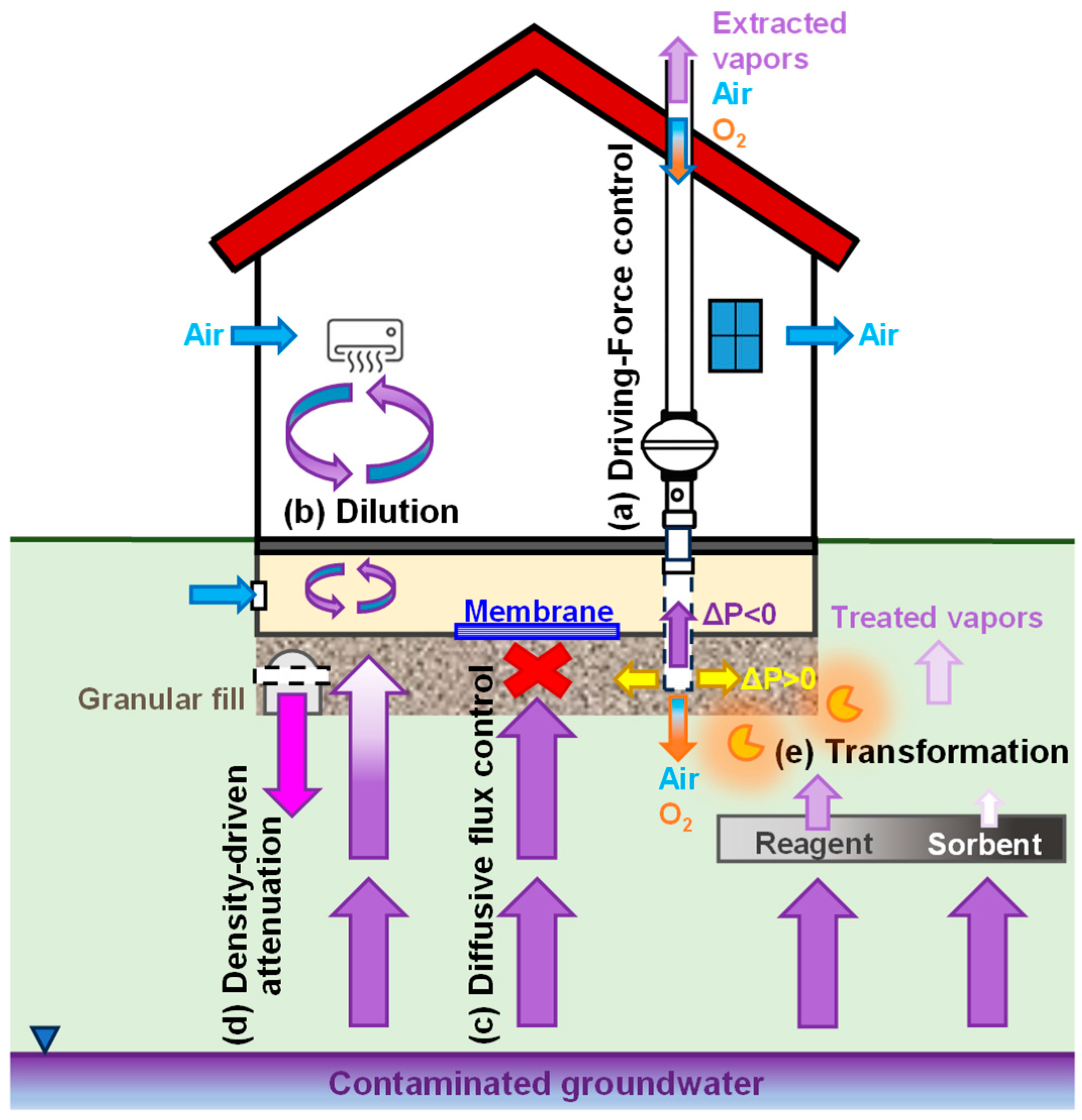
To overcome this limitation, a process-oriented framework is required that explicitly links the mitigation technology performance to the governing transport and transformation phenomena of contaminated vapors, thereby supporting more robust and site-specific decision-making. In this context, the present study proposes a mechanistic classification of CVI mitigation systems based on the dominant physical and chemical processes controlling vapor transport and attenuation in the unsaturated zone. Rather than grouping technologies according to their configuration or operational mode, the proposed framework organizes mitigation approaches into five process-based categories: (a) driving-force control through pressure gradient manipulation, (b) concentration reduction via dilution, (c) diffusive flux limitation through physical barriers, (d) density-driven attenuation mechanisms, and (e) subsurface treatment based on transformation and retardation processes (see Figure 1).
By framing mitigation options in terms of governing transport and transformation processes, this classification provides a rational basis for strategy selection that is consistent with site-specific conditions and long-term performance objectives, supporting the identification of solutions that minimize energy consumption and reduce lifecycle maintenance requirements.

2. Processes Controlling Chlorinated Vapor Intrusion

The assessment and mitigation of chlorinated vapor intrusion require a clear understanding of the physical and chemical processes that control vapor migration in the unsaturated zone [18]. Mitigation systems are often described as active or passive, depending on the energy usage [12,17,23]. However, their effectiveness depends on how they influence the dominant transport and transformation mechanisms at a given site. Vapor-phase chlorinated solvents in the vadose zone are governed by molecular diffusion, advection induced by pressure or density gradients, phase interactions such as sorption, and chemical or biological transformation [20,31,32,33,34]. These processes can occur simultaneously [33]. However, their relative importance depends on soil permeability, contaminant concentration, moisture content, building characteristics, and environmental conditions [31,33,35]. This section summarizes the processes that control CVI and provides the foundation for the process-based classification of mitigation strategies presented in the next section.

2.1. Diffusion-Dominated Vapor Transport

At many contaminated sites, vapor migration in the unsaturated zone is primarily controlled by molecular diffusion [18,36,37,38,39]. Diffusion occurs in response to concentration gradients between a contaminant source, such as impacted groundwater or residual DNAPL, and overlying receptors including building foundations or the atmosphere [39]. Under steady state conditions and in the absence of significant pressure gradients, Fickian diffusion is the main mechanism driving upward vapor transport [18,31,34,40,41,42].
The effective diffusion coefficient in porous media depends on the effective porosity, air-filled porosity, water saturation, and temperature [6,18,42,43,44,45]. Increasing moisture content in the soil reduces gas-phase connectivity and lower effective diffusivity [41,42,45,46]. In contrast, coarse and dry soils favor higher vapor mobility [46]. Diffusion-dominated conditions are common in low-permeability formations and under buildings that do not induce strong pressure differentials [5,11,47,48]. In these situations, mitigation measures that increase resistance to diffusive flux, such as low-permeability barriers, directly target the prevailing transport process [18,23].

2.2. Pressure-Driven Advection

Advective transport occurs when gas flow is induced by pressure gradients in the subsurface and/or between subsurface and indoor air [23,33,42,47]. These gradients may result from temperature differences between indoor and outdoor environments, wind effects on the building envelope, operation of ventilation systems, or changes in barometric pressure [18,32,41]. When indoor pressure is lower than sub-slab soil gas pressure, contaminated vapors can migrate into buildings through cracks, joints, and utility penetrations [18,41,49].
Even pressure differences of a few Pascals can generate substantial advective fluxes in permeable soils [11,17]. Pressure-driven advection often controls short-term variability in indoor vapor concentrations [50,51]. It is also the main mechanism addressed by conventional mitigation systems such as sub-slab depressurization, which modifies the pressure field to reverse advective flow [52,53]. The magnitude and spatial extent of this process depend strongly on porous media permeability and sub-slab connectivity [51]. Pressure perturbations can extend several meters in highly permeable materials, while their influence is more limited in fine-grained soils [47,49,50,51].

2.3. Density-Driven Advection

Chlorinated solvents such as trichloroethylene and tetrachloroethylene generate vapors that are denser than ambient soil gas [54,55,56]. At elevated concentrations and in sufficiently permeable media, this density contrast can induce gravity-driven flow [31,55,57]. In coarse-grained or engineered high-permeability sub-slab layers, the resulting downward flux may partially counteract upward diffusion [55]. The influence of this mechanism increases as vapor concentration and permeability rise, allowing buoyancy forces to approach or exceed diffusive driving forces [55,56,57,58]. Unlike pressure-driven advection, density-driven flow is not imposed by building operation or atmospheric variability but originates from contaminant properties and concentration gradients [31]. It may therefore contribute to passive attenuation and should be considered in foundation design where permeable layers are installed beneath slabs.

2.4. Sorption and Retardation Processes

As vapors migrate through the vadose zone, they interact with soil solid particles and organic matter through sorption [6,33,42]. This process retards vapor transport and leads to temporary storage of contaminants within the porous medium [33]. Sorption depends on soil organic carbon content, mineral surface properties, contaminant characteristics, temperature, and moisture conditions [42,59]. In natural soils, sorption generally provides partial attenuation, but it rarely prevents vapor migration entirely. Engineered systems can enhance this mechanism by introducing materials characterized by high surface area and organic carbon content, such as activated carbon or biochar [60,61,62]. Sorption-based approaches reduce vapor flux and delay contaminant breakthrough [60]. However, these strategies do not eliminate contaminant mass but only retain it. Long-term performance depends on several factors such as adsorption capacity of the material, competitive adsorption, desorption behavior, and material aging [60,63]. These processes form the basis of mitigation strategies that rely on adsorptive barriers.

2.5. Reactive Transformation Processes

Chlorinated solvents may undergo chemical or biological transformation in the subsurface [1,2,3,6,7,9,31,33]. Specifically, abiotic reactions include reductive dehalogenation induced by zero-valent iron or iron sulfide and oxidation promoted by strong oxidants [9,64,65,66,67]. Instead, biotic degradation may occur under aerobic or anaerobic conditions, depending on redox state, moisture content, and substrate availability [16,68]. However, in the unsaturated zone its overall contribution is often limited by low water content, reduced microbial activity, and mass transfer constraints, and is therefore typically less significant than in saturated systems [10]. Transformation processes reduce contaminant mass through degradation rather than through redirection or dilution of vapor flux [15]. Their efficiency depends on several factors, such as reaction kinetics, mass transfer limitations, temperature, moisture, and the persistence of reactive capacity. Engineered reactive layers placed in the unsaturated zone represent an approach in which contaminant attenuation occurs before vapors reach building foundations [15,65,67,69].

3. Process-Based Classification of CVI Mitigation Strategies

In this study, the mitigation systems were classified into five categories according to the primary process they affect within the vapor intrusion pathway (see Table 1 and Figure 1). This proposed framework aims to clarify how different approaches modify specific transport and attenuation mechanisms occurring between the subsurface and the building. Driving-force control strategies (Figure 1a) modify the pressure field to regulate advective soil gas movement. Dilution-based strategies (Figure 1b) reduce vapor concentrations through controlled air exchange rates. Diffusive flux control strategies (Figure 1c) are based on the use of physical barriers to limit vapor migration by increasing resistance to diffusive transport and reducing preferential entry pathways. Density-driven attenuation strategies (Figure 1d) take advantage of vapor density contrasts to promote downward advection within permeable sub-slab layers. Finally, in situ transformation strategies (Figure 1e) reduce contaminant mass within the subsurface through sorption, retardation, or chemical and biological degradation processes. The following sections describe the techniques associated with each category.

3.1. Driving-Force Control Strategies

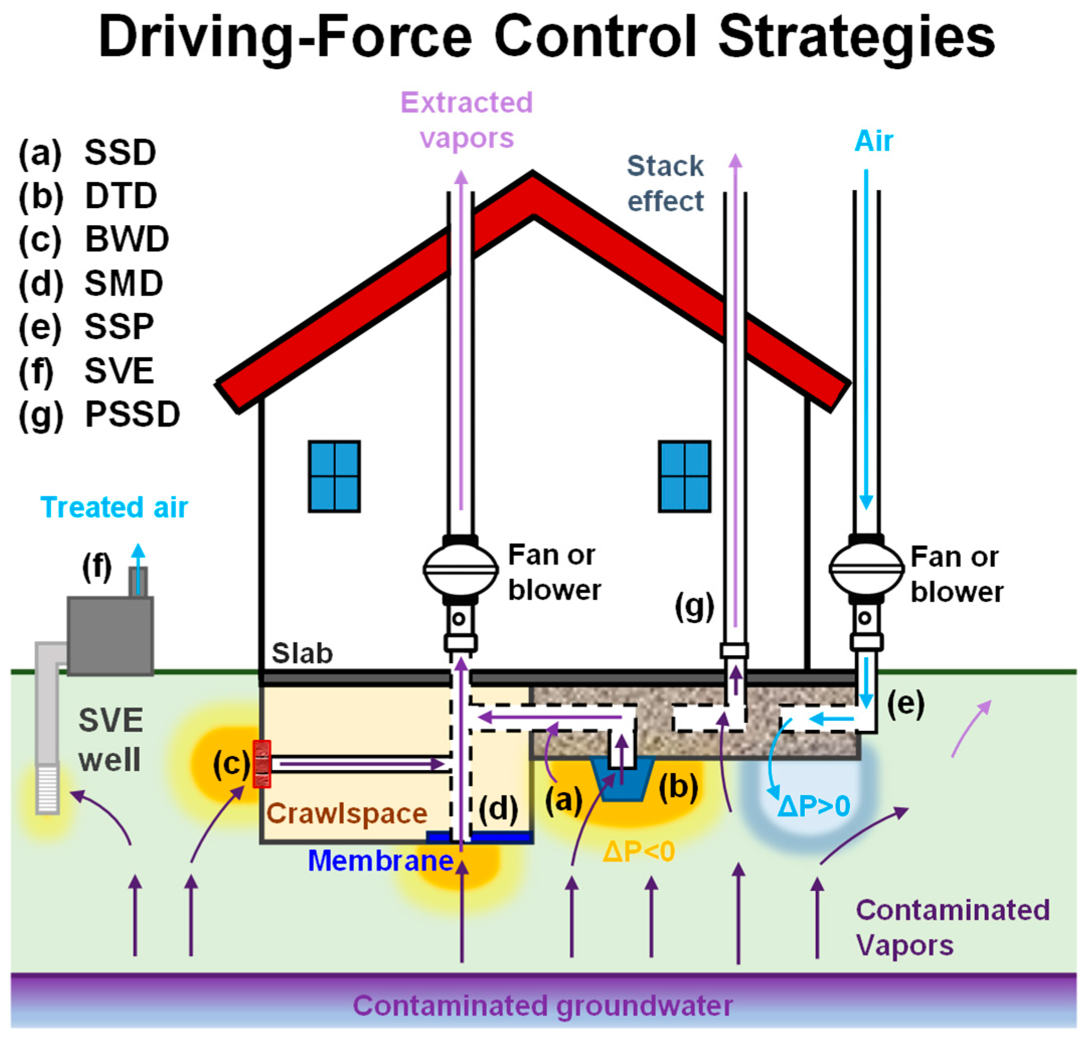
Driving-force control strategies include remediation and mitigation techniques designed to alter the pressure gradients and advective flow conditions that govern vapor migration from the subsurface into buildings [23]. These approaches either induce negative pressure to intercept and extract contaminated vapors or create positive pressure conditions to prevent their inward migration. The category includes both active systems, such as Soil Vapor Extraction (SVE), Sub-Slab Depressurization (SSD) and its variants (DTD, BWD, SMD), and Sub-Slab Pressurization (SSP), as well as passive configurations like Passive Sub-Slab Depressurization (PSSD).
Figure 2 illustrates the main driving-force control strategies discussed in this section, highlighting their conceptual configurations and the mechanisms through which they modify subsurface pressure conditions to reduce vapor intrusion.

3.1.1. Soil Vapor Extraction (SVE)

Soil Vapor Extraction (SVE) (Figure 2f) is an in situ remediation technology that removes volatile contaminants from unsaturated soils by applying vacuum to extraction wells, thereby inducing vapor flow toward the extraction system [3,74,116]. Extracted vapors are collected and treated at the surface prior to discharge into the atmosphere [70,72,117,118]. SVE has been widely used for more than three decades to address chlorinated solvents and other volatile organic compounds in the vadose zone [13,72,73].
Although primarily developed for source remediation, SVE can also be used as a vapor intrusion mitigation strategy [18,24,53,73]. By creating a negative pressure zone in the subsurface, it induces outward advective flow beneath buildings, intercepting contaminated vapors before they migrate indoors [24,74]. Its effectiveness depends on soil permeability, and surface sealing may be required to enhance vacuum propagation and prevent clean air intrusion [13].
SVE can be applied at both small and large scales [24,73]. For individual buildings, installation can be relatively rapid [24]. At larger sites, centralized systems may provide area-wide mitigation, as demonstrated by field studies reporting reductions in indoor TCE and PCE concentrations at distances of up to 200 ft from the source [73].
Compared with conventional depressurization systems (see next section), SVE may require less intrusive property access but necessitates vapor treatment units [119,120,121]. While capital costs can be lower, operating expenses are generally higher [53]. In dense urban settings, however, SVE may offer cost advantages due to the combined benefit of mitigation and source removal [53].

3.1.2. Active Depressurization/Pressurization Systems (SSD, DTD, BWD, SMD and SSP)

Active depressurization and pressurization systems represent well-established methods for vapor intrusion mitigation [18,23]. Among these, Sub-Slab Depressurization (SSD) (Figure 2a) is the most widely applied and is generally considered the most practical solution for addressing chlorinated vapor intrusion [18,53,77,122,123]. SSD uses electric fans to create a negative pressure zone beneath the building slab, reversing the pressure gradient and inducing outward advective flow that prevents vapor entry through cracks and openings [76,122,124]. Extracted vapors are vented to the atmosphere [76,125,126], and effective operation typically requires maintaining a pressure differential of 4–10 Pa across the slab [17,23,98]. SSD can be implemented in both new and existing buildings [17,23,76], and its performance has been documented at sites impacted by chlorinated solvents, including large residential areas [30,35,75,77,78,127]. Although capital costs are generally lower than SVE-based mitigation [53], preferential pathways may significantly reduce system effectiveness [122].
Variants of SSD include Drain Tile Depressurization (DTD) (Figure 2b) and Block Wall depressurization (BWD) (Figure 2c) [17,124,128,129]. DTD applies negative pressure through existing perimeter drainage systems connected to a fan [129], providing a cost-effective alternative where such infrastructure is present [23]. Interior drain tiles can enhance sub-slab pressure control near slab–wall joints, whereas exterior systems are generally less effective toward the slab center [17]. BWD applies suction to hollow block wall cavities to reduce vapor entry through foundation walls [17,129]. Due to limited pressure propagation, BWD is typically used as a supplement to SSD, particularly in buildings with block wall foundations [17,28].
Submembrane Depressurization (SMD) (Figure 2d) extends the SSD principle to crawlspaces or basements with exposed soil [17,23,130]. A sealed membrane is installed over the soil surface, and negative pressure is induced beneath it to intercept vapors before they enter the building [79,129]. This approach combines physical containment (see Section 3.3) with active depressurization and is effective when proper sealing is achieved [17]. Membranes are typically polyethylene sheets with thicknesses of 75–150 μm [23,126], although durability considerations limit applicability in frequently accessed areas [23,79,124].
In contrast, Sub-Slab Pressurization (SSP) (Figure 2e) increases pressure beneath the slab to create a positive gradient that prevents inward vapor migration [17,18,23,130]. SSP may be advantageous in highly permeable soils where establishing sufficient negative pressure is challenging [17,23]. However, cracks or openings may allow air recirculation, potentially reducing effectiveness [17]. Because air must be forced into the subsurface, SSP generally entails higher energy consumption than SSD [23].

3.1.3. Passive Depressurization (PSSD)

Passive Sub-Slab depressurization (PSSD) (Figure 2g) reduces sub-slab pressure relative to indoor air without the use of mechanical fans [23]. The system consists of a vent pipe connecting the sub-slab region to the outdoor atmosphere, typically conveyed through conditioned indoor space [19,23]. Airflow is driven by natural thermal and pressure gradients. Temperature differences between the subsurface and the building interior induce upward convective flow in the vent pipe through the stack effect [19,23]. In addition, wind flowing over the roof can create a low-pressure zone that enhances vapor extraction [19,81]. Wind turbines may be installed to support venting [23].
Although PSSD mitigates vapor intrusion through these natural driving forces, airflow rates and pressure differentials are generally lower and more variable than in active SSD systems [19,23]. Performance may fluctuate with weather conditions and indoor temperature variations that influence the stack effect [19,81]. To achieve adequate mitigation, passive systems may require multiple suction points, potentially increasing capital costs compared to active configurations [23]. However, the absence of energy demand makes PSSD relatively more sustainable compared to the active option [19], though effectiveness is affected by environmental factors (e.g., weather conditions variation).
Passive systems are most effective when incorporated into new construction, where venting layers and piping can be integrated into the foundation design [23,80]. Their performance may also be enhanced in existing buildings under favorable site conditions, such as highly permeable sub-slab materials or aerated floor spaces [19].

3.2. Dilution-Based Strategies

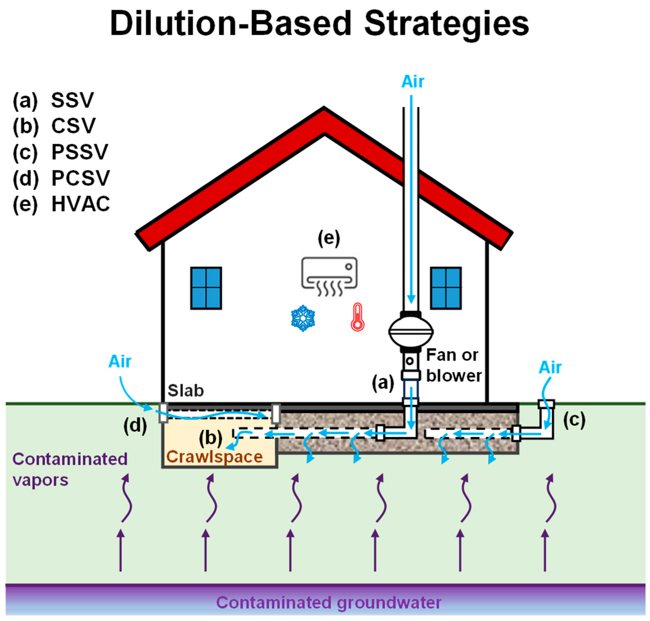
Dilution-based strategies comprise mitigation approaches aimed at reducing indoor contaminant concentrations by increasing airflow and air exchange in subsurface, crawlspace, or indoor environments [82,85,88]. Unlike driving-force control techniques, which primarily modify pressure gradients to reverse advective flow, these methods focus on lowering vapor concentrations through dilution and controlled ventilation [82]. The category includes both active systems, such as Sub-Slab Ventilation (SSV) and Crawlspace Ventilation (CSV), and passive configurations, including Passive Sub-Slab Ventilation (PSSV), Passive Crawlspace Ventilation (PCSV), as well as the use of Heating, Ventilating, and Air-Conditioning (HVAC) systems to enhance indoor air exchange [17,23].
Figure 3 presents the principal dilution-based strategies addressed in this section, illustrating their conceptual configurations and the mechanisms through which increased airflow and ventilation contribute to vapor intrusion mitigation.

3.2.1. Active Ventilation Systems (SSV and CSV)

Active ventilation strategies mitigate vapor intrusion by increasing airflow in subsurface or crawlspace zones to dilute contaminant concentrations [23,30,123]. Sub-Slab Ventilation (SSV) (Figure 3a) introduces and evacuates air beneath the slab to reduce vapor concentrations and promote removal [82,123]. Its effectiveness depends on sufficient sub-slab permeability, such as in coarse granular fill, to allow adequate airflow [52,123]. SSV is particularly suitable where vapor concentrations are moderate and can be reduced to acceptable levels through dilution rather than strong pressure reversal [23].
Crawlspace Ventilation (CSV) (Figure 3b) similarly mitigates vapor intrusion by increasing the air exchange rate within crawlspaces, typically targeting 1–3 h−1 to dilute contaminant [17,23,84]. Effective operation may require sealing to isolate the crawlspace [84]. In high-risk scenarios, however, submembrane depressurization generally provides more robust control than CSV alone [84].

3.2.2. Passive Ventilation Systems (PSSV and PCSV)

Passive ventilation systems rely on natural driving forces rather than mechanical fans to induce airflow beneath slabs or within crawlspaces [85]. Air movement is generated by wind effects or temperature differences that create convective flow and promote contaminant dilution [85,130]. Passive Sub-Slab Ventilation (PSSV) (Figure 3c) directs vapors away from the building through vent pipes installed beneath the slab, whereas Passive Crawlspace Ventilation (PCSV) (Figure 3c) enhances airflow within crawlspaces [23,85].
These systems are commonly combined with vapor barriers or geomembranes (see next section) to improve performance [23,87]. However, airflow rates are generally lower and more variable than in active systems, making performance dependent on weather and site conditions [23,29]. Passive systems require highly permeable materials to install the venting pipes and careful construction to function effectively [23,86]. They are most suitable for new construction, where venting networks and barriers can be integrated into the foundation design [17]. Implementation in existing buildings is typically more challenging and expensive, although passive systems can be converted to active by adding a fan if needed [17,87].

3.2.3. Heating, Ventilating, and Air-Conditioning (HVAC)

Heating, Ventilating, and Air-Conditioning (HVAC) systems (Figure 3d) influence vapor intrusion primarily by increasing the indoor air exchange rate, thereby diluting contaminant concentrations [89,90,124]. Depending on system configuration, they may also generate positive indoor pressure relative to the subsurface, which can further limit advective vapor entry [17,23,41].
HVAC-based mitigation is generally more feasible in commercial or industrial buildings, where airflow and pressure conditions can be more effectively controlled [90]. Field studies have shown effective performance in commercial settings [89,90], whereas results in residential buildings are more variable and often influenced by environmental factors [91]. Successful application requires a relatively airtight building envelope and ongoing monitoring of airflow balance and pressure differentials [89,90]. Although not specifically designed for vapor intrusion control, HVAC systems can provide supplementary mitigation when properly managed [17,23].

3.3. Diffusive Flux Control Strategies

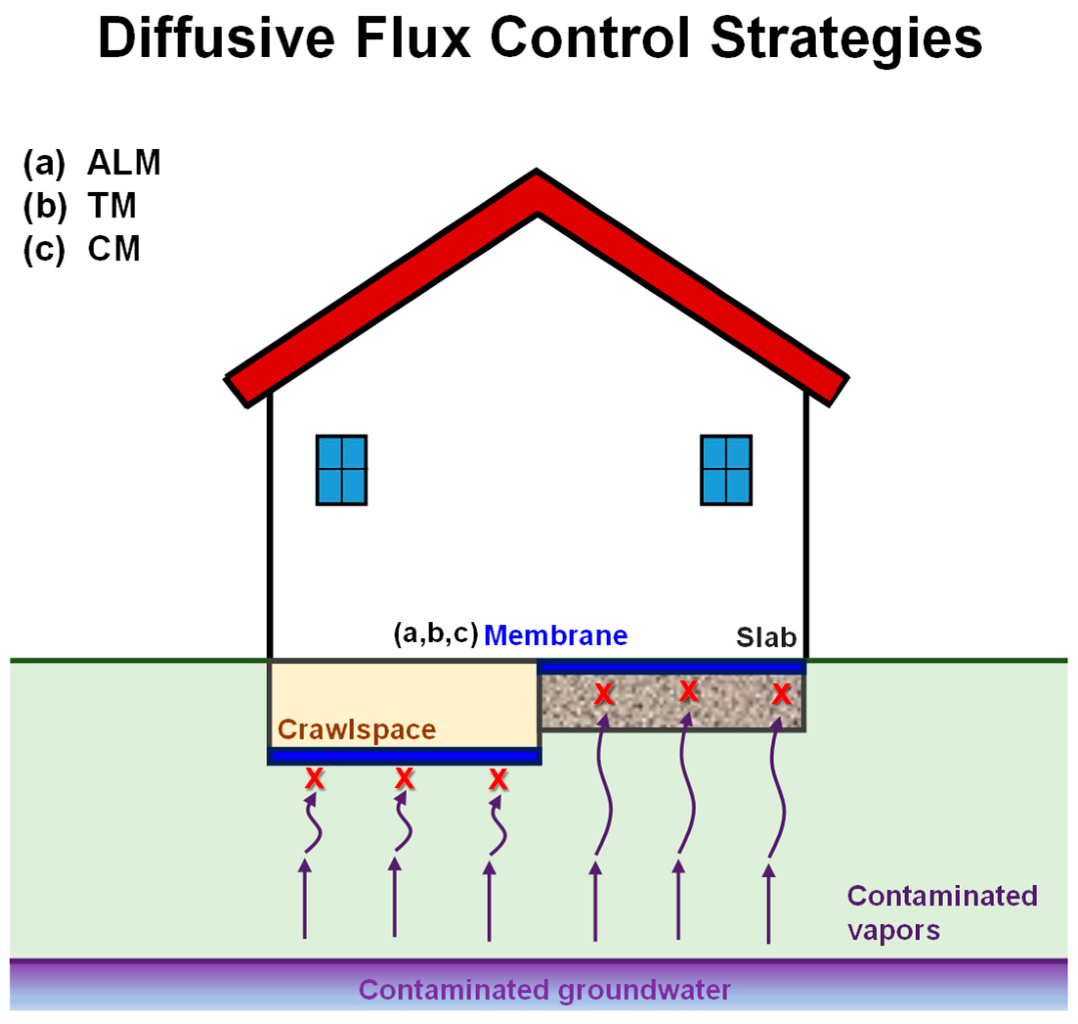
Diffusive flux control strategies are based on physical vapor barrier strategies, which rely on low-permeability materials installed beneath the slab to limit soil gas entry through cracks and construction joints [23,94,130]. These systems increase resistance to diffusive transport and restrict preferential pathways by forcing vapors to migrate laterally beyond the building footprint [17,92].
However, passive barriers alone rarely ensure complete vapor control [17]. Their performance depends on installation quality, as even minor defects or incomplete sealing can create preferential pathways, particularly under underpressurized conditions [92]. Construction activities or long-term degradation may further compromise integrity [92]. For this reason, physical vapor barriers are generally not recommended as standalone solutions [19,131] and are more effective when combined with depressurization or ventilation systems, including SMD configurations [17,77,92]. Although primarily used in new construction, they may also be applied in existing buildings where feasible [92].
Passive vapor barriers (Figure 4) are commonly classified as Asphalt Latex Membranes (ALMs), Thermoplastic Membranes (TMs), and Composite Membranes (CMs) [92,93].

3.3.1. Asphalt–Latex Membranes (ALM)

Asphalt–Latex Membranes (ALMs) are spray-applied systems composed of a liquid rubberized asphalt or polymer-modified latex layer installed over a prepared substrate and typically protected by a cap layer to enhance mechanical durability and bonding with the overlying slab [23,92,93]. The spray application allows the membrane to form a continuous, seamless layer that conforms to penetrations, joints, and irregular geometries, reducing the risk of preferential leakage pathways [92]. Rapid curing enables efficient installation and limits construction delays [23].
ALMs generally provide low vapor permeability and good chemical resistance to chlorinated solvents, while maintaining flexibility to accommodate minor differential settlement or structural movement [92]. Their ability to adhere to materials such as concrete, steel, poly-vinylchloride (PVC), and wood facilitates integration with foundation elements and utility penetrations [68]. Commercial products, including Liquid Boot® (CETCO, Houston, TX, USA) have been widely implemented in vapor intrusion mitigation projects [17,83,93].

3.3.2. Thermoplastic Membranes (TM)

Thermoplastic Membranes (TM) are low-permeability sheets typically made of high-density polyethylene (HDPE), low-density polyethylene (LLDPE), poly-vinylchloride (PVC), ethylene vinyl alcohol (EVOH) or ethylene–propylene–diene monomer (EDPM), with typical thicknesses of 0.75–1.5 mm [23,94,95]. They are installed over prepared subgrades, often with protective geotextiles [23]. Experimental studies have demonstrated their effectiveness in significantly reducing chlorinated vapor diffusion, particularly when used in multilayer configurations [92,94].

3.3.3. Composite Membranes (CM)

Composite Membranes (CM) combine multiple materials to improve chemical resistance, durability, and constructability [92]. Systems integrating HDPE layers with spray-applied components, such as Geo-Seal™ (EPRO Services, Inc., Wichita, KS, USA), have shown effective vapor mitigation at contaminated sites [93]. Multilayer approaches including polymer- or biopolymer-amended clay barriers have also demonstrated reduced VOC transport [96,97].

3.4. Density-Driven Attenuation Strategies

Density-driven attenuation strategies include building-related features that can passively influence vapor transport as a result of density differences between contaminant vapors and ambient soil gas. For chlorinated solvents such as TCE and PCE, whose vapors are denser than ambient soil-gas, specific sub-foundation configurations may favor downward advective flow when permeability and vapor concentrations are sufficiently high, partially counterbalancing upward diffusion toward indoor spaces [55]. Unlike active mitigation systems or ventilation-based approaches, these strategies do not rely on mechanical intervention but on the physical characteristics of the contaminant of concern to support natural attenuation mechanisms.
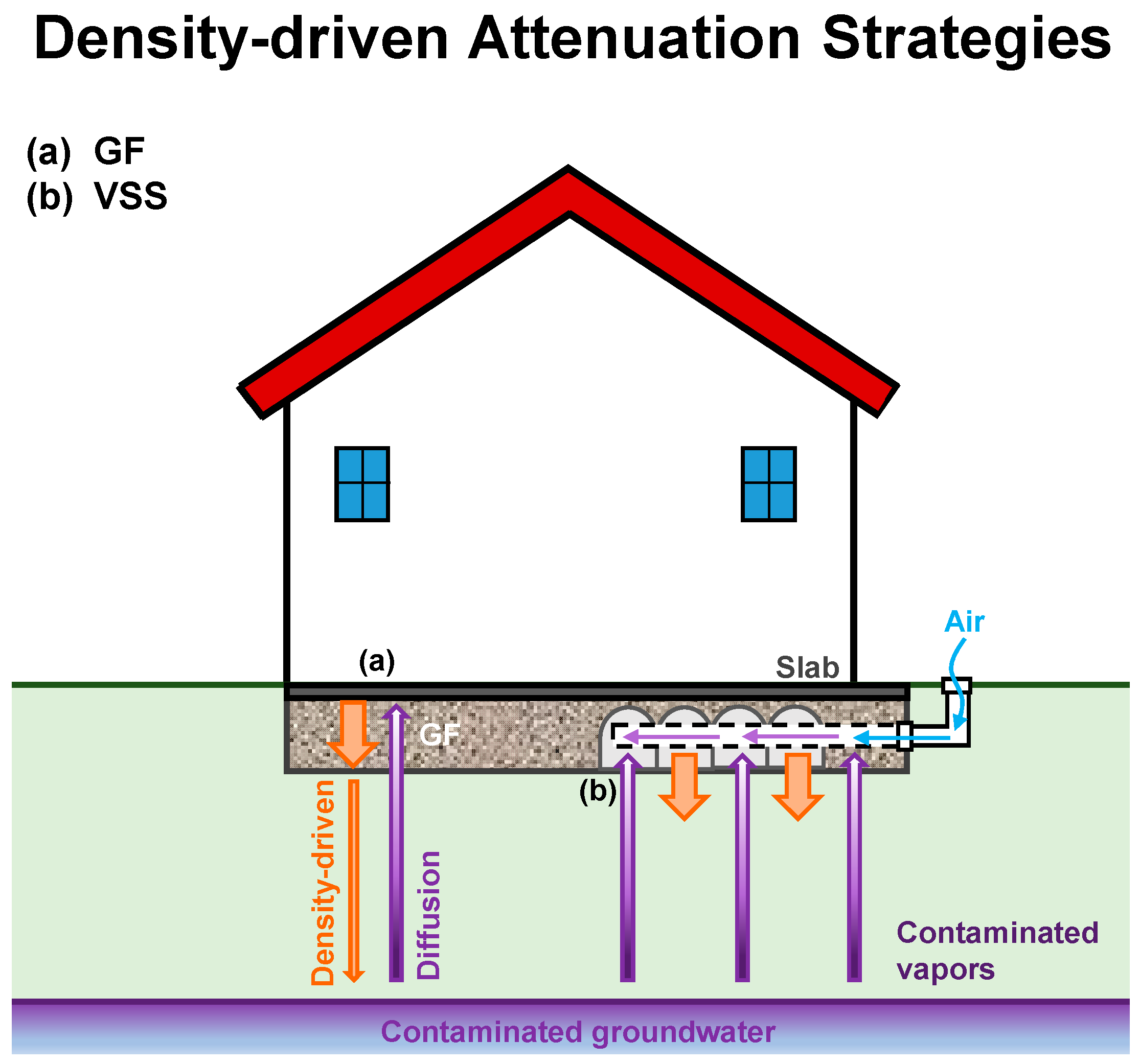
Figure 5 presents the main configurations considered within this category, namely high-permeability Granular Fill layers (GF) and aerated floor Void Space Systems (VSS), both of which can facilitate density-driven transport and contribute to reduced sub-slab vapor concentrations under suitable site conditions.

3.4.1. High Permeable Granular Fill Layers (GF)

Buildings are commonly constructed over a layer of clean granular fill (GF) placed beneath the slab to provide drainage and moisture control [132,133]. These materials exhibit high permeability [134], which can influence vapor transport beneath foundations.
For chlorinated solvents such as TCE and PCE, whose vapors are denser than ambient soil gas, sufficiently high permeability and vapor concentrations may induce density-driven advection [56,57,58,135]. Under these conditions, downward advective flow can partially counteract upward diffusion, leading to reduced sub-slab vapor concentrations [55].
Recent modeling and experimental studies have shown that high-permeability granular layers can promote significant attenuation of chlorinated vapors when source vapor concentrations exceed threshold values [55]. Specifically, for GF layers permeabilities exceeding 10−7 m2, density-driven attenuation is expected to become relevant at vapor concentrations of 1 mg m−3, while for lower permeabilities (10−8–10−10 m2), attenuation is expected for higher vapor concentrations, exceeding 1 g m−3 [55]. In contrast, geometric factors such as layer thickness or groundwater depth appear to exert a limited influence on this mechanism [55]. Modeling results on density-driven attenuation aligned with extensive field data for chlorinated solvents vapors from several databases showing attenuation by increasing vapor source concentrations [55].
These novel results indicate that granular fill layers characterized by high permeability, beyond their structural and drainage functions, may contribute to passive attenuation of chlorinated vapor intrusion under appropriate site conditions (Figure 5a). However, granular fill layers used as attenuation strategy due to density-driven advection have been mainly investigated through modeling and controlled experimental studies, therefore dedicated field validation is still limited.

3.4.2. Aerated Floor Void Space System (VSS)

Aerated floor Void Space Systems (VSS) (Figure 5b) create a continuous, highly permeable cavity beneath the slab, providing substantially lower resistance to gas flow than conventional granular layers [98,99]. These systems are typically formed using modular plastic forms installed prior to concrete placement, generating interconnected voids [99]. Commercial products such as Ventform (Cordek Ltd., West Sussex, UK) and Cupolex® (Pontarolo Engineering, San Vito al Tagliamento, Italy) are commonly used [86,98].
The high permeability of the void space promotes uniform airflow distribution and enhances the performance of both active and passive ventilation or depressurization systems [98,99]. In addition, by minimizing resistance to gas movement, VSS may facilitate density-driven transport where sufficient vapor concentration gradients exist, thereby supporting passive attenuation mechanisms under suitable conditions.
VSS are primarily implemented in new construction but may also be used during major renovations or slab replacement [99]. Increased oxygen availability within the void space may further promote aerobic biodegradation of susceptible compounds [99].

3.5. In Situ Transformation Strategies

In situ transformation strategies encompass subsurface systems specifically designed to reduce vapor-phase contaminant mass through chemical, physico-chemical, or biological reactions occurring before vapors reach the building. Rather than primarily controlling pressure gradients or enhancing dilution, these approaches aim to transform chlorinated compounds into less harmful products or to immobilize them within reactive or sorptive media installed in the unsaturated zone [60,104].
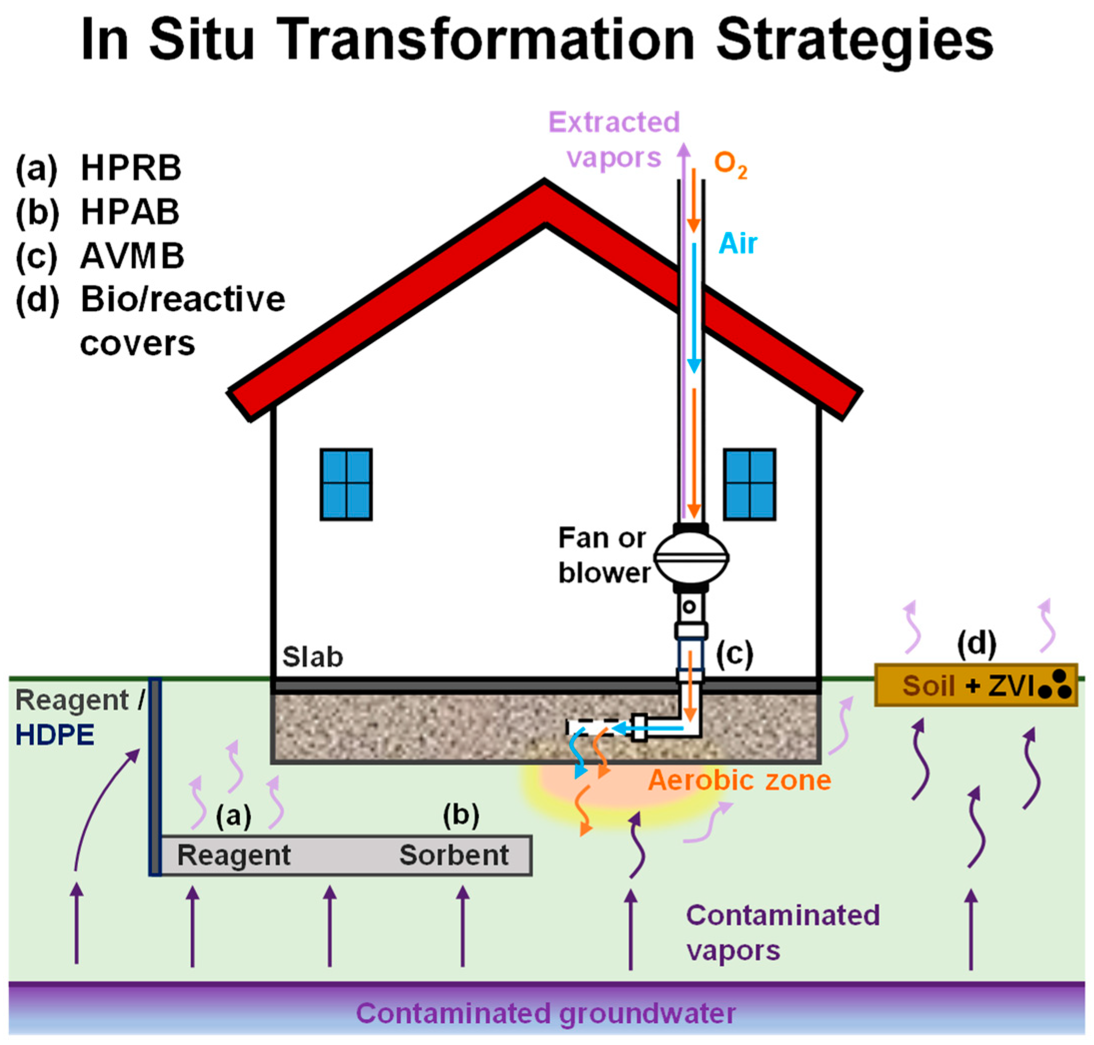
This category includes Horizontal Permeable Reactive Barriers (HPRBs), Horizontal Permeable Adsorbing Barriers (HPABs), Aerobic Vapor Migration Barriers (AVMBs), and biological or reactive cover systems, such as biocovers, biofilters or reactive covers. As illustrated in Figure 6, barrier configurations are placed between the contaminant source and the building foundation or atmosphere, where they function as treatment layers that attenuate contaminant fluxes within the vadose zone, while cover configurations are mainly posed as capping to address volatilization and release of contaminated vapors in the atmosphere (i.e., soil or landfill capping).

3.5.1. Horizontal Permeable Reactive Barriers (HPRB)

Horizontal Permeable Reactive Barriers (HPRBs) recently emerged as novel passive mitigation strategy for addressing chlorinated vapor emissions in the subsurface. HPRBs consist of reactive layers installed in the unsaturated zone between the contaminant source and the overlying building to promote in situ degradation of chlorinated vapors (Figure 6a) [15,65,67]. Conceptually analogous to vertical Permeable Reactive Barriers (PRBs) used in groundwater remediation [64,136,137], HPRBs transform chlorinated compounds, such as TCE and PCE, into less harmful products through chemical reactions occurring within the reactive medium [65,67].
Oxidative HPRBs using potassium permanganate (KMnO4) have been investigated through laboratory and modeling studies [67,106]. Analytical and numerical models demonstrated that barriers with a vertical thickness of less than 1 m can provide proper and relatively durable attenuation under suitable conditions [15,65,67]. However, soluble oxidants may progressively dissolve and leach due to infiltration, limiting long-term durability [15].
To address this limitation, zero-valent iron (ZVI) has been proposed as a more stable filling material due to its low solubility [65,102]. ZVI promotes reductive dehalogenation of chlorinated vapors, converting them into simple hydrocarbons through hydrogenolysis and β-elimination pathways [66,136]. Laboratory studies demonstrated effective TCE degradation under varying environmental conditions, with performance influenced by humidity, oxygen availability, and material dilution with sand [65,102]. Modified ZVI materials, including bimetallic ZVI–Ni or ZVI–Cu [103,104] and sulfidated ZVI [105] have shown enhanced reactivity and improved resistance to passivation. Modeling results indicate that required barrier thickness may range from approximately 1 m for ZVI to less than 20 cm for modified materials [65,103,104,105].
Recent 2-D numerical modeling incorporating lateral bypass flow highlighted the importance of barrier configuration, showing that combining horizontal reactive layers with vertical or low-permeability elements improves overall attenuation performance [69]. The current level of evidence highlights that HPRBs are promising emerging passive mitigation strategies for addressing chlorinated vapor intrusion, though further higher scale validation is still needed for addressing critical technical aspects and long-term durability under field conditions.

3.5.2. Horizontal Permeable Adsorbing Barriers (HPAB)

Horizontal Permeable Adsorbing Barriers (HPABs) were recently proposed as chlorinated vapor intrusion passive mitigation strategy [60]. HPABs consist of sorbent layers installed in the unsaturated zone to mitigate chlorinated vapor emissions through adsorption processes (Figure 6b) [60]. Similar to vertical permeable adsorbing barriers used in aquifers [63,138,139], these systems rely on transfer contaminants from vapors to the solid phase, controlled by adsorbent properties and environmental conditions, such as humidity and temperature [60,140].
Generally, carbonaceous materials have been widely investigated for chlorinated vapors adsorption applications [60,140,141]. While activated carbon is commonly used for VOC treatment [72], biochar and coal ash derived from biomass pyrolysis or gasification have emerged as lower-cost and more sustainable alternatives [60,140]. Such materials were involved in HPAB development, and experimental and modeling studies demonstrated effective TCE vapors adsorption under variable environmental conditions [60]. For example, based on experiments and modeling, a 0.5 m thick biochar barrier may achieve half-time durations exceeding 15 years at moderate vapor concentrations, although higher source concentrations reduce longevity and may require increased thickness [60]. These findings support HPABs as promising emerging passive mitigation options for chlorinated vapors, though further field validation is still limited and needed.
Sorbent-based capping systems using biochar have also been proposed to reduce vapor emissions at contaminated sites [61].

3.5.3. Aerobic Vapor Migration Barriers (AVMB)

Aerobic Vapor Migration Barriers (AVMBs) are designed to promote in situ biodegradation by increasing oxygen availability in the sub-slab region (Figure 6c) [108]. The system typically combines low-pressure vapor extraction with controlled air injection beneath the foundation. This configuration establishes a continuous circulation of atmospheric air through the unsaturated zone, maintaining elevated oxygen concentrations in the soil gas [108].
The enhanced oxygen supply stimulates aerobic microbial activity within the porous medium. As contaminated vapors migrate through the oxygenated zone, biodegradable compounds are oxidized by indigenous microorganisms, reducing contaminant mass before vapors reach the building interior [109]. In this sense, AVMB systems differ from conventional depressurization systems because their primary objective is not only flow control but also enhancement of biological transformation.
Field studies have demonstrated effective attenuation of aerobically degradable hydrocarbons with lower energy demand compared to extraction-only systems [109]. For chlorinated solvents, AVMB effectiveness is limited to compounds susceptible to aerobic degradation, such as vinyl chloride. Compounds that require anaerobic reductive dehalogenation, including TCE and PCE, are not effectively treated under aerobic conditions and therefore cannot be controlled by this approach. In this context, the application of anaerobic vapor migration barriers is also challenging in the shallow vadose zone underneath buildings, where atmospheric oxygen diffusion limits the persistence of anaerobic conditions needed for inducing degradation.

3.5.4. Bio/Reactive Covers

Biocovers and Biofilters (Figure 6d) have primarily been developed to control gaseous emissions from landfills and contaminated soils rather than as building-specific vapor intrusion mitigation systems [21,113,142,143]. Nevertheless, such systems are relevant in the context of chlorinated vapor management at contaminated sites because they are able to reduce vapor fluxes in the unsaturated zone through physicochemical processes (i.e., sorption, biological reactions).
Biocovers consist of biologically active layers composed of soil, compost, or carbonaceous materials that promote microbial degradation of gaseous contaminants [25,143,144,145]. Although originally implemented to enhance methane oxidation [25,111,143], laboratory studies have shown that lower chlorinated compounds, including vinyl chloride (VC) and dichloroethylene (DCE), can undergo aerobic or cometabolic degradation within these systems, while fully halogenated compounds, such as PCE, are less susceptible to aerobic biodegradation [25,111,115].
Full-scale applications have reported attenuation of trace chlorinated vapors in landfill gas emissions [112,113,114]. In addition, reactive top covers amended with zero-valent iron have been proposed to promote anaerobic degradation pathways for selected chlorinated compounds [26], with enhanced performance observed for modified ZVI-based materials with added catalysts [110].

4. Longevity, Resilience, and Selection of Mitigation Strategies

4.1. System Longevity and Maintenance Cycles

The long-term reliability of vapor intrusion mitigation systems depends largely on the mechanism responsible for attenuation. Because the five mitigation categories differ in operational requirements, material durability, and reactive capacity, they exhibit distinct longevity profiles.
Driving-force control strategies provide rapid and measurable attenuation by actively manipulating the subsurface pressure field [27,123]. Their performance, however, depends on sustained mechanical operation. Maintaining a stable pressure differential requires continuous fan operation, periodic inspection, and verification of pressure conditions [17]. System effectiveness can decline because of mechanical degradation, power interruptions, or changes in soil moisture and slab integrity. Regular inspection is therefore required to maintain performance.
Dilution-based strategies similarly rely on continuous airflow to maintain adequate air exchange rates [23]. Although typically less pressure-intensive than depressurization systems, their long-term effectiveness remains contingent upon uninterrupted operation and building ventilation control.
In contrast, physical barrier and density-driven attenuation strategies are inherently passive [55,92] and therefore not subject to mechanical failure. Their durability depends instead on material integrity and preservation of subsurface hydraulic properties. Polymer membranes may degrade due to aging, puncturing, or prolonged chemical exposure. Density-driven systems require sustained gas-phase permeability within granular layers, which may be affected by moisture redistribution or soil consolidation.
In situ transformation systems introduce a distinct longevity constraint. Rather than mechanical wear or structural degradation, their lifespan is governed by depletion of reactive media, passivation of reactive surfaces, or exhaustion of sorption capacity [60,105]. Effective design therefore requires estimating contaminant mass flux so that the reactive lifetime of the treatment system matches the expected persistence of the vapor source.

4.2. Resilience to Climatic Fluctuations and Subsurface Dynamics

Beyond intrinsic durability, the resilience of mitigation strategies to environmental variability is essential for long-term risk management.
Mechanisms based on pressure manipulation or dilution are directly influenced by atmospheric drivers such as barometric pressure fluctuations, wind loading, and seasonal indoor-outdoor temperature gradients [18,41]. These factors may induce temporal variability in system performance, particularly in passive configurations where pressure fields are not mechanically controlled.
Active depressurization systems are less sensitive to climatic variability because they impose a controlled pressure gradient [23]. However, their resilience remains dependent on continuous energy supply and mechanical reliability.
Density-driven attenuation and in situ transformation strategies are generally less sensitive to short-term atmospheric variability because their performance depends primarily on vapor density, reaction kinetics, and subsurface conditions. Nevertheless, all mechanisms are influenced by subsurface dynamics. Variations in soil moisture, capillary fringe elevation, and gas permeability may alter advective and diffusive transport pathways, affecting both density-driven redistribution and reactive contact efficiency.
Physical barriers are largely insensitive to atmospheric fluctuations but may be vulnerable to structural discontinuities or long-term material degradation [92].

4.3. Strategic Transition Toward Lifecycle-Oriented Mitigation

The comparative evaluation of longevity, operational dependence, and environmental resilience across the five mechanistic categories highlights the need for a structured decision framework. To support mechanism-based selection, Table 2 summarizes the dominant control processes, representative technologies, key design parameters, applicability constraints, and qualitative operational and carbon implications associated with each category.
This table provides a basis for aligning mitigation strategies with site-specific transport dynamics, required response time, and long-term sustainability objectives.
The comparison of mitigation mechanisms indicates that no single approach is universally optimal. Mechanisms that provide greater control over vapor transport generally require higher operational effort, energy input, and maintenance. Conversely, approaches with lower operational demands may rely more strongly on favorable site conditions and the long-term preservation of key system properties. Transformation- and retardation-based mechanisms provide an alternative pathway by reducing contaminant mass or mobility, although their long-term effectiveness depends on maintaining sufficient reactive capacity. Consequently, mitigation selection should consider not only immediate risk reduction, but also lifecycle performance, operational requirements, and long-term resilience.
Driving-force control systems remain the most reliable option for rapid risk reduction, especially in low-permeability soils and high-concentration settings. Their main limitation is the need for continuous energy input and regular maintenance, which increases lifecycle costs and carbon emissions.
Physical barriers and density-driven attenuation offer passive alternatives with minimal operational energy demand. Their effectiveness depends on installation quality and preservation of subsurface gas permeability, making them particularly suitable for new construction or controlled redevelopment settings.
In situ transformation and retardation strategies represent a shift from vapor flux redirection to contaminant mass reduction. When designed to accommodate the expected contaminant load, these systems can provide long-term attenuation while requiring little operational energy. As a result, they are well aligned with sustainable remediation principles.
Dilution-based strategies are generally appropriate for moderate-risk conditions or as supplementary safety measures. Because their performance depends on building airtightness and climatic variability, they are less suited as primary mechanisms in high-risk contexts.
A lifecycle-oriented strategy may combine different mitigation mechanisms over time. Active driving-force control can be used during the initial high-flux phase to achieve rapid risk reduction. As vapor concentrations decline, passive or in situ approaches may become sufficient to maintain long-term protection with lower energy demand. Such hybrid strategies integrate rapid risk reduction with improved long-term resilience and sustainability.

5. Conclusions

This work advances the discussion on chlorinated vapor intrusion mitigation by shifting from a technology-centered perspective to a process-based framework grounded in vadose-zone transport and transformation mechanisms.
By classifying mitigation systems according to their dominant physical and chemical controls, the proposed scheme clarifies how different strategies modify diffusion, advection, density-driven flow, sorption, and reactive degradation. This mechanistic interpretation enables a more transparent comparison of performance, durability, and climate resilience across system types.
The analysis confirms that active driving-force control remains the most reliable solution for rapid risk reduction, whereas emerging passive approaches, such as density-driven attenuation and horizontal reactive or adsorptive barriers offer promising low-energy alternatives for long-term management, although further field validation is required and performance depends on several factors (e.g., installation quality, maintenance and monitoring requirements, material aging, evolving subsurface conditions).
Overall, the proposed framework provides a structured basis for lifecycle-oriented and sustainability-informed selection of CVI mitigation strategies.

Author Contributions

Conceptualization, C.S., D.Z. and I.V.; Methodology, C.S., D.Z. and I.V.; Writing—original draft preparation, C.S. and I.V.; Writing—review and editing, D.Z. and I.V.; Visualization, C.S., D.Z. and I.V.; Supervision, D.Z., R.B. and I.V. All authors have read and agreed to the published version of the manuscript.

Funding

This research received no external funding.

Data Availability Statement

No new data was created in this study. The data can be retrieved in the cited references.

Conflicts of Interest

The authors declare no conflicts of interest.

Abbreviations

The following abbreviations are used in this manuscript:
ACActivated Carbon
ALMAsphalt–Latex Membrane
AVMBAerobic Vapor Migration Barrier
BWDBlock Wall Depressurization
CSVCrawlspace Ventilation
CMComposite Membrane
CVIChlorinated Vapor Intrusion
DCEDichloroethylene
DNAPLDense Non-Aqueous Phase Liquids
DTDDrain Tile Depressurization
EDPMEthylene–Propylene–Diene Monomer
EVOHEthylene Vinyl Alcohol
GFGranular Fill layers
HDPEHigh-Density Polyethylene
HPABHorizontal Permeable Adsorbing Barrier
HPBHorizontal Permeable Barrier
HPRBHorizontal Permeable Reactive Barrier
HVACHeating Ventilating Air Conditioning
LLDPELow-Density Polyethylene
PCETetrachloroethylene
PCSVPassive Crawlspace Ventilation
PSSDPassive Sub-Slab Depressurization
PSSVPassive Sub-Slab Ventilation
PVCPoly Vinylchloride
SMDSubmembrane Depressurization
SSDSub-Slab Depressurization
SSPSub-Slab Pressurization
SSVSub-Slab Ventilation
SVESoil Vapor Extraction
TCETrichloroethylene
TMThermoplastic Membrane
VCVinyl Chloride
VIVapor Intrusion
VOCVolatile Organic Compound
VSSVoid Space System
ZVIZero-Valent Iron

References

  1. Huang, B.; Lei, C.; Wei, C.; Zeng, G. Chlorinated Volatile Organic Compounds (Cl-VOCs) in Environment—Sources, Potential Human Health Impacts, and Current Remediation Technologies. Environ. Int. 2014, 71, 118–138. [Google Scholar] [CrossRef] [Scilit]
  2. U.S. EPA. In Situ Thermal Treatment of Chlorinated Solvents: Fundamentals and Field Applications. 2004. Available online: https://19january2017snapshot.epa.gov/remedytech/situ-thermal-treatment-chlorinated-solvents-fundamentals-and-field-applications_.html (accessed on 1 September 2024).
  3. Naidu, R. The Old and New Persistent Organic Pollutants: Sources, Risks, Regulations, and Remediation, 1st ed.; CRC Press: Boca Raton, FL, USA, 2025; pp. 1–410. ISBN 978-1-003-53046-6. [Google Scholar]
  4. Kim, J.-H.; Kim, J.; Bae, M.S.; Lee, S. Assessment of Vapor Intrusion Risks in Chlorinated Solvent-Contaminated Subsurface Environments: Implications for Environmental Quality Standards in Urban Areas. Indoor Air 2025, 2025, 8867246. [Google Scholar] [CrossRef] [Scilit]
  5. Wanner, P.; Parker, B.L.; Hunkeler, D. Assessing the Effect of Chlorinated Hydrocarbon Degradation in Aquitards on Plume Persistence Due to Back-Diffusion. Sci. Total Environ. 2018, 633, 1602–1612. [Google Scholar] [CrossRef] [Scilit]
  6. Rivett, M.O.; Wealthall, G.P.; Dearden, R.A.; McAlary, T.A. Review of Unsaturated-Zone Transport and Attenuation of Volatile Organic Compound (VOC) Plumes Leached from Shallow Source Zones. J. Contam. Hydrol. 2011, 123, 130–156. [Google Scholar] [CrossRef] [Scilit]
  7. Koenig, J.; Lee, M.; Manefield, M. Aliphatic Organochlorine Degradation in Subsurface Environments. Rev. Environ. Sci. Biotechnol. 2015, 14, 49–71. [Google Scholar] [CrossRef] [Scilit]
  8. Pankow, J.F.; Cherry, J.A. Dense Chlorinated Solvents and Other DNAPLs in Groundwater: History, Behavior, and Remediation; Waterloo Press: East Sussex, UK, 1996; Volume 362, pp. 15–50. [Google Scholar]
  9. Kueper, B.H.; Stroo, H.F.; Vogel, C.M.; Ward, C.H. (Eds.) Chlorinated Solvent Source Zone Remediation; Springer: New York, NY, USA, 2014; pp. 82–114. ISBN 978-1-4614-6921-6. [Google Scholar] [CrossRef] [Scilit]
  10. Semprini, L. In Situ Bioremediation of Chlorinated Solvents. Environ. Health Perspect. 1995, 103, 101–115. [Google Scholar] [PubMed]
  11. Ma, J.; McHugh, T.; Beckley, L.; Lahvis, M.; DeVaull, G.; Jiang, L. Vapor Intrusion Investigations and Decision-Making: A Critical Review. Environ. Sci. Technol. 2020, 54, 7050–7069. [Google Scholar] [CrossRef] [Scilit] [PubMed]
  12. Eklund, B.; Regan, C.; Rago, R.; Beckley, L. Overview of State Approaches to Vapor Intrusion: 2023 Update. Groundw. Monit. Rem. 2024, 44, 76–93. [Google Scholar] [CrossRef] [Scilit]
  13. Brusseau, M.L.; Carroll, K.C.; Truex, M.J.; Becker, D.J. Characterization and Remediation of Chlorinated Volatile Organic Contaminants in the Vadose Zone. Vadose Zone J. 2013, 12, vzj2012.0137. [Google Scholar] [CrossRef] [Scilit]
  14. Yao, Y.; Shen, R.; Pennell, K.G.; Suuberg, E.M. A Review of Vapor Intrusion Models. Environ. Sci. Technol. 2013, 47, 2457–2470. [Google Scholar] [CrossRef] [Scilit] [PubMed]
  15. Verginelli, I.; Capobianco, O.; Hartog, N.; Baciocchi, R. Analytical Model for the Design of in Situ Horizontal Permeable Reactive Barriers (HPRBs) for the Mitigation of Chlorinated Solvent Vapors in the Unsaturated Zone. J. Contam. Hydrol. 2017, 197, 50–61. [Google Scholar] [CrossRef] [Scilit] [PubMed]
  16. U.S. EPA. Petroleum Hydrocarbons and Chlorinated Solvents Differ in Their Potential for Vapor Intrusion. 2012. Available online: https://www.epa.gov (accessed on 1 September 2025).
  17. ITRC. Vapor Intrusion Pathway: A Practical Guideline. 2007. Available online: https://semspub.epa.gov/work/01/533755.pdf (accessed on 5 December 2025).
  18. McAlary, T.A.; Provoost, J.; Dawson, H.E. Vapor Intrusion. In Dealing with Contaminated Sites; Swartjes, F.A., Ed.; Springer: Dordrecht, The Netherlands, 2011; pp. 409–453. ISBN 978-90-481-9756-9. [Google Scholar]
  19. NJDEP. New Jersey Department of Environmental Protection Site Remediation and Waste Management Program. Vapor Intrusion Technical Guidance. 2018. Available online: https://dep.nj.gov/wp-content/uploads/srp/vig_main_4.1.pdf (accessed on 5 December 2025).
  20. U.S. EPA. OSWER Technical Guide for Assessing and Mitigating the Vapor Intrusion Pathway from Subsurface Vapor Sources to Indoor Air. 2015. Available online: https://www.epa.gov/sites/default/files/2015-09/documents/oswer-vapor-intrusion-technical-guide-final.pdf (accessed on 20 March 2025).
  21. Duan, Z.; Scheutz, C.; Kjeldsen, P. Trace Gas Emissions from Municipal Solid Waste Landfills: A Review. Waste Manag. 2021, 119, 39–62. [Google Scholar] [CrossRef] [Scilit] [PubMed]
  22. Pan, Q.; Liu, Q.-Y.; Zheng, J.; Li, Y.-H.; Xiang, S.; Sun, X.-J.; He, X.-S. Volatile and Semi-Volatile Organic Compounds in Landfill Gas: Composition Characteristics and Health Risks. Environ. Int. 2023, 174, 107886. [Google Scholar] [CrossRef] [Scilit]
  23. U.S. EPA. Indoor Air Vapor Intrusion Mitigation Approaches. 2008. Available online: https://www.epa.gov/sites/default/files/2015-09/documents/600r08115.pdf (accessed on 1 September 2025).
  24. ITRC Remediation and Institutional Controls as Vapor Intrusion Mitigation. 2020. Available online: https://vim-1.itrcweb.org/wp-content/uploads/2020/12/1-fact-sheet-remediaton-fs-forwebdev-2020-11.pdf (accessed on 1 January 2025).
  25. Scheutz, C.; Mosb, H. Attenuation of Methane and Volatile Organic Compounds in Landfill Soil Covers. J. Environ. Qual. 2004, 33, 61–71. [Google Scholar] [CrossRef]
  26. Scheutz, C.; Winther, K.; Kjeldsen, P. Removal of Halogenated Organic Compounds in Landfill Gas by Top Covers Containing Zero-Valent Iron. Environ. Sci. Technol. 2000, 34, 2557–2563. [Google Scholar] [CrossRef] [Scilit]
  27. ITRC. Active Vapor Intrusion Mitigation Systems Fact Sheet. 2026. Available online: https://itrcweb.org/vapor-intrusion-toolkit (accessed on 1 February 2026).
  28. ITRC. Active Mitigation Fact Sheet. 2020. Available online: https://vim-1.itrcweb.org/wp-content/uploads/2020/12/1-fact-sheet-active-mitigation-fs-forwebdev-2020-11.pdf (accessed on 1 February 2025).
  29. ITRC. Passive Mitigation Fact Sheet. 2020. Available online: https://vim-1.itrcweb.org/wp-content/uploads/2020/12/1-fact-sheet-passive-mitigation-fs-forwebdev-2020-11.pdf (accessed on 1 July 2025).
  30. Crump, D.; Brown, V.; Rowley, J.; Squire, R. Reducing Ingress of Organic Vapours into Homes Situated on Contaminated Land. Environ. Technol. 2004, 25, 443–450. [Google Scholar] [CrossRef] [Scilit]
  31. Tillman, F.D.; Weaver, J.W. Review of Recent Research on Vapor Intrusion; EPA/600/R-05/106; U. S. Environmental Protection Agency Office of Research and Development: Washington, DC, USA, 2005. Available online: https://nepis.epa.gov/ (accessed on 10 June 2025).
  32. McHugh, T.; Loll, P.; Eklund, B. Recent Advances in Vapor Intrusion Site Investigations. J. Environ. Manag. 2017, 204, 783–792. [Google Scholar] [CrossRef] [Scilit]
  33. U.S. EPA. Conceptual Model Scenarios for the Vapor Intrusion Pathway. 2012. Available online: https://www.epa.gov/sites/default/files/2015-09/documents/vi-cms-v11final-2-24-2012.pdf (accessed on 1 September 2025).
  34. Provoost, J. Soil Contamination and Indoor Air Quality. The Accuracy and Conservatism of Screening-Level Algorithms for Vapour Intrusion of VOC into Buildings; Springer: Berlin/Heidelberg, Germany, 2013. [Google Scholar] [CrossRef]
  35. Erdogan, H.; Hsieh, H.-N. Evaluation of Air Quality in Buildings Located Above TCE and Chloroform Contaminated Plume—A Field Study. In Proceedings of the 3rd Residential Building Design & Construction Conference; Penn State University Park: University Park, PA, USA, 2016; Available online: https://www.phrc.psu.edu (accessed on 20 July 2025).
  36. Verginelli, I.; Yao, Y. A Review of Recent Vapor Intrusion Modeling Work. Groundw. Monit. Rem. 2021, 41, 138–144. [Google Scholar] [CrossRef] [Scilit]
  37. You, K.; Zhan, H. Comparisons of Diffusive and Advective Fluxes of Gas Phase Volatile Organic Compounds (VOCs) in Unsaturated Zones under Natural Conditions. Adv. Water Resour. 2013, 52, 221–231. [Google Scholar] [CrossRef] [Scilit]
  38. Conant, B.H.; Gillham, R.W.; Mendoza, C.A. Vapor Transport of Trichloroethylene in the Unsaturated Zone: Field and Numerical Modeling Investigations. Water Resour. Res. 1996, 32, 9–22. [Google Scholar] [CrossRef] [Scilit]
  39. Massmann, J.; Farrier, D.F. Effects of Atmospheric Pressures on Gas Transport in the Vadose Zone. Water Resour. Res. 1992, 28, 777–791. [Google Scholar] [CrossRef] [Scilit]
  40. Fen, C.-S.; Tsoa, C.; Yen, P. Upward Transport of Trichloroethylene Vapour in a Dry Soil Column. Environ. Process 2021, 8, 239–250. [Google Scholar] [CrossRef] [Scilit]
  41. McHugh, T.E.; McAlary, T. Important Physical Processes for Vapor Intrusion: A Literature Review. In Proceedings of the AWMA Vapor Intrusion Conference; Air & Waste Management Association (A&WMA): Pittsburgh, PA, USA, 2009. [Google Scholar]
  42. Unnithan, A.; Bekele, D.N.; Chadalavada, S.; Naidu, R. Insights into Vapour Intrusion Phenomena: Current Outlook and Preferential Pathway Scenario. Sci. Total Environ. 2021, 796, 148885. [Google Scholar] [CrossRef] [Scilit] [PubMed]
  43. Sleep, B.E.; Sykes, J.F. Modeling the Transport of Volatile Organics in Variably Saturated Media. Water Resour. Res. 1989, 25, 81–92. [Google Scholar] [CrossRef] [Scilit]
  44. Thomson, N.R.; Sykes, J.F.; Van Vliet, D. A Numerical Investigation into Factors Affecting Gas and Aqueous Phase Plumes in the Subsurface. J. Contam. Hydrol. 1997, 28, 39–70. [Google Scholar] [CrossRef] [Scilit]
  45. Eklund, B. Climatic Effects on Vapor Flow and Behavior in the Vadose Zone. Groundw. Monit. Rem. 2024, 44, 80–91. [Google Scholar] [CrossRef] [Scilit]
  46. Yao, Y.; Shen, R.; Pennell, K.G.; Suuberg, E.M. Examination of the Influence of Environmental Factors on Contaminant Vapor Concentration Attenuation Factors Using the U.S. EPA’s Vapor Intrusion Database. Environ. Sci. Technol. 2013, 47, 906–913. [Google Scholar] [CrossRef] [Scilit]
  47. Sookhak Lari, K.; Davis, G.B.; Rayner, J.L.; Bastow, T.P. Advective and Diffusive Gas Phase Transport in Vadose Zones: Importance for Defining Vapour Risks and Natural Source Zone Depletion of Petroleum Hydrocarbons. Water Res. 2024, 255, 121455. [Google Scholar] [CrossRef] [Scilit] [PubMed]
  48. Yao, Y.; Chen, Q. Screening Models of Vapor Intrusion. In Vapor Intrusion Simulations and Risk Assessments; Springer: Singapore, 2022. [Google Scholar] [CrossRef] [Scilit]
  49. Unnithan, A.; Bekele, D.N.; Chadalavada, S.; Naidu, R. Two-Dimensional Chlorinated Vapour Intrusion Model Involving Advective Transport of Vapours with a Highly Permeable Granular Layer in the Vadose Zone Serving as the Preferential Pathway. Sci. Total Environ. 2023, 869, 161743. [Google Scholar] [CrossRef] [Scilit]
  50. Kim, H.; Kim, P.-G.; Moon, J.; Yoon, J.; Hong, Y. Importance of Advection-Driven Soil Vapor Intrusion: Effects of Atmospheric and Indoor Pressure Variations. Water Air Soil. Pollut. 2024, 235, 277. [Google Scholar] [CrossRef] [Scilit]
  51. Yao, Y.; Xiao, Y.; Luo, J.; Wang, G.; Ström, J.; Suuberg, E. High-Frequency Fluctuations of Indoor Pressure: A Potential Driving Force for Vapor Intrusion in Urban Areas. Sci. Total Environ. 2020, 710, 136309. [Google Scholar] [CrossRef] [Scilit]
  52. McAlary, T.A. Subslab Depressurization Versus Subslab Ventilation: Insights from Recent Research. Groundw. Monit. Rem. 2021, 41, 132–137. [Google Scholar] [CrossRef] [Scilit]
  53. Lutes, C.; Stewart, L.; Truesdale, R.; De Loera, J.; Zimmerman, J.H.; Schumacher, B. Cost Comparison of Soil Vapor Extraction and Subslab Depressurization for Vapor Intrusion Mitigation. Groundw. Monit. Remediat. 2022, 42, 43–53. [Google Scholar] [CrossRef] [Scilit]
  54. Cotel, S.; Schäfer, G.; Barthes, V.; Baussand, P. Effect of Density-Driven Advection on Trichloroethylene Vapor Diffusion in a Porous Medium. Vadose Zone J. 2011, 10, 565–581. [Google Scholar] [CrossRef] [Scilit]
  55. Settimi, C.; Verginelli, I.; Zingaretti, D. Examining the Role of Density-Driven Transport on Chlorinated Vapor Intrusion. Build. Environ. 2024, 266, 112096. [Google Scholar] [CrossRef] [Scilit]
  56. Mendoza, C.A.; Frind, E.O. Advective-dispersive Transport of Dense Organic Vapors in the Unsaturated Zone: 2. Sensitivity Analysis. Water Resour. Res. 1990, 26, 388–398. [Google Scholar] [CrossRef] [Scilit]
  57. Falta, R.W.; Javandel, I.; Pruess, K.; Witherspoon, P.A. Density-driven Flow of Gas in the Unsaturated Zone Due to the Evaporation of Volatile Organic Compounds. Water Resour. Res. 1989, 25, 2159–2169. [Google Scholar] [CrossRef] [Scilit]
  58. Barnes, D.L.; McRae, M.F. The Predictable Influence of Soil Temperature and Barometric Pressure Changes on Vapor Intrusion. Atmos. Environ. 2017, 150, 15–23. [Google Scholar] [CrossRef] [Scilit]
  59. Ahn, J.; Rao, G.; Mamun, M.; Vejerano, E.P. Soil–Air Partitioning of Volatile Organic Compounds into Soils with High Water Content. Environ. Chem. 2020, 17, 545–557. [Google Scholar] [CrossRef] [Scilit]
  60. Settimi, C.; Conti, B.; Verginelli, I.; Zingaretti, D.; Bortone, I.; Coulon, F.; Baciocchi, R. Use of Biochar and Coal Ash as Passive Sorbent Barriers for Long-Term Mitigation of Chlorinated Solvent Vapours. J. Environ. Manag. 2025, 391, 126501. [Google Scholar] [CrossRef] [Scilit]
  61. Wang, S.; Song, L.; He, H.; Zhang, W. Volatile Organic Compounds (VOCs) in Soil: Transport Mechanisms, Monitoring, and Removal by Biochar-Modified Capping Layer. Coatings 2024, 14, 270. [Google Scholar] [CrossRef] [Scilit]
  62. Sadasivam, B.Y.; Reddy, K.R. Adsorption and Transport of Methane in Biochars Derived from Waste Wood. Waste Manag. 2015, 43, 218–229. [Google Scholar] [CrossRef] [Scilit]
  63. Erto, A.; Bortone, I.; Di Nardo, A.; Di Natale, M.; Musmarra, D. Permeable Adsorptive Barrier (PAB) for the Remediation of Groundwater Simultaneously Contaminated by Some Chlorinated Organic Compounds. J. Environ. Manag. 2014, 140, 111–119. [Google Scholar] [CrossRef] [Scilit] [PubMed]
  64. McCarty, P.L. Groundwater Contamination by Chlorinated Solvents: History, Remediation Technologies and Strategies. In In Situ Remediation of Chlorinated Solvent Plumes; Stroo, H.F., Ward, C.H., Eds.; SERDP/ESTCP Environmental Remediation Technology; Springer: New York, NY, USA, 2010; pp. 1–28. ISBN 978-1-4419-1400-2. [Google Scholar]
  65. Zingaretti, D.; Verginelli, I.; Luisetto, I.; Baciocchi, R. Horizontal Permeable Reactive Barriers with Zero-Valent Iron for Preventing Upward Diffusion of Chlorinated Solvent Vapors in the Unsaturated Zone. J. Contam. Hydrol. 2020, 234, 103687. [Google Scholar] [CrossRef] [Scilit]
  66. Liu, Y.; Majetich, S.A.; Tilton, R.D.; Sholl, D.S.; Lowry, G.V. TCE Dechlorination Rates, Pathways, and Efficiency of Nanoscale Iron Particles with Different Properties. Environ. Sci. Technol. 2005, 39, 1338–1345. [Google Scholar] [CrossRef] [Scilit]
  67. Mahmoodlu, M.G.; Hassanizadeh, S.M.; Hartog, N.; Raoof, A.; van Genuchten, M.T. Evaluation of a Horizontal Permeable Reactive Barrier for Preventing Upward Diffusion of Volatile Organic Compounds through the Unsaturated Zone. J. Environ. Manag. 2015, 163, 204–213. [Google Scholar] [CrossRef] [Scilit] [PubMed]
  68. Bekele, D.N.; Naidu, R.; Bowman, M.; Chadalavada, S. Vapor Intrusion Models for Petroleum and Chlorinated Volatile Organic Compounds: Opportunities for Future Improvements. Vadose Zone J. 2013, 12, vzj2012-0048. [Google Scholar] [CrossRef] [Scilit]
  69. Tonolo, N.; Settimi, C.; Zingaretti, D.; Baciocchi, R.; Verginelli, I. Incorporating Lateral Bypass in the Design of Horizontal Permeable Reactive Barriers (HPRBs) for Chlorinated Vapor Intrusion Mitigation. Build. Environ. 2025, 284, 113468. [Google Scholar] [CrossRef] [Scilit]
  70. U.S. ACE. Department of the Army US Army Corps of Engineers. In Soil Vapor Extraction and Bioventing; US Army Corps of Engineers: Fort Belvoir, VA, USA, 1995. Available online: https://www.publications.usace.army.mil/portals/76/publications/engineermanuals/em_1110-1-4001.pdf (accessed on 1 September 2024).
  71. Truex, M.J.; Becker, D.; Simon, M.A.; Oostrom, M.; Rice, A.K.; Johnson, C.D. Soil Vapor Extraction System Optimization, Transition, and Closure Guidance; Pacific Northwest National Laboratory (PNNL): Richland, WA, USA, 2013; p. PNNL-21843. [Google Scholar]
  72. U.S. EPA. Soil Vapor Extraction (SVE) Technology. EPA/600/R-18/053. 2018. Available online: https://www.epa.gov/research (accessed on 1 December 2025).
  73. Stewart, L.; Lutes, C.; Truesdale, R.; Schumacher, B.; Zimmerman, J.; Connell, R. Field Study of Soil Vapor Extraction for Reducing Off-Site Vapor Intrusion. Groundw. Monit. Remediat. 2020, 40, 74–85. [Google Scholar] [CrossRef] [Scilit]
  74. ITRC. Soil Vapor Extraction (SVE) Applicability as a Method of Vapor Intrusion (VI) Mitigation. 2020. Available online: https://vim-1.itrcweb.org (accessed on 5 November 2025).
  75. Folkes, D.; Kurz, D. Efficacy of Sub-Slab Depressurization for Mitigation of Vapor Intrusion of Chlorinated Organic Compounds. In Proceedings of the Indoor Air 2002, Monterey, CA, USA, 30 June–5 July 2002. [Google Scholar]
  76. ITRC. Sub-Slab Depressurization (SSD). Active Mitigation Systems. 2020. Available online: https://vim-1.itrcweb.org/wp-content/uploads/2020/12/4-sub-slab-depressurization-vimt-ssd-ts-forwebdev-2020-11.pdf (accessed on 1 September 2025).
  77. Glass, D.S.; DiPilato, J.; Boger, K. Vapor Intrusion Mitigation: Road Map to Successful Sub-Slab Depressurization at Sites with Shallow Water Tables. Environ. Prog. Sustain. Energy 2018, 37, 1758–1761. [Google Scholar] [CrossRef] [Scilit]
  78. Rydock, J.P.; Skaret, E. A Case Study of Sub-Slab Depressurization for a Building Located over VOC-Contaminated Ground. Build. Environ. 2002, 37, 1343–1347. [Google Scholar] [CrossRef] [Scilit]
  79. ITRC. Sub-Membrane Depressurization (SMD). Active Mitigation Systems. 2020. Available online: https://vim-1.itrcweb.org/wp-content/uploads/2020/12/3-sub-membrane-vimt-smd-ts-forwebdev-2020-11.pdf (accessed on 1 September 2025).
  80. Zhou, L.G.; Berquist, J.; Li, Y.E.; Whyte, J.; Gaskin, J.; Vuotari, M.; Nong, G. Passive Soil Depressurization in Canadian Homes for Radon Control. Build. Environ. 2021, 188, 107487. [Google Scholar] [CrossRef] [Scilit]
  81. Abdelouhab, M.; Collignan, B.; Allard, F. Experimental Study on Passive Soil Depressurisation System to Prevent Soil Gaseous Pollutants into Building. Build. Environ. 2010, 45, 2400–2406. [Google Scholar] [CrossRef] [Scilit]
  82. ITRC. Sub-Slab Ventilation (SSV). Active Mitigation Systems. 2020. Available online: https://vim-1.itrcweb.org/wp-content/uploads/2020/12/5-sub-slab-ventilation-vimt-ssv-ts-forwebdev-2020-11.pdf (accessed on 8 September 2025).
  83. Hatton, T.E. Designing Efficient Sub Slab Venting and Vapor Barrier Systems for Schools and Large Buildings. 2010. Available online: https://www.vapordynamics.com/uploads/1/4/7/3/14733700/2_designing_efficient_sub_slab_venting.vapor_barrier_systems.schools.large_buildings.pdf (accessed on 20 January 2026).
  84. ITRC. Crawlspace Ventilation (CSV). Active Mitigation Systems. 2020. Available online: https://vim-1.itrcweb.org/wp-content/uploads/2020/12/2-crawlspace-vimt-csv-ts-forwebdev-2020-11.pdf (accessed on 1 June 2025).
  85. ITRC. Passive Sub-Slab Venting Systems. Vapor Intrusion Mitigation Team. 2020. Available online: https://vim-1.itrcweb.org/wp-content/uploads/2020/12/6-passive-sub-slab-venting-vimt_passive-sub-slab-venting-systems-ts-forwebdev-2020-11.pdf (accessed on 1 September 2025).
  86. Garetto, A.; Davit, J.P.; Hersb, I.; Kocioleka, P.; Battista, A. Passive Vapour Barrier Feasibility Study: Redevelopment of an Industrial Site to a Residential Site. Chem. Eng. Trans. 2012, 28, 49–54. [Google Scholar] [CrossRef] [Scilit]
  87. Ash, J.R.; Ensign, M.C.; Simons, W.F. Sustainable Vapor Intrusion Controls—Designing an Effective Passive System. In Proceedings of the Air & Waste Management Association’s Vapor Intrusion 2010 Conference; Air & Waste Management Association (A&WMA): Pittsburgh, PA, USA, 2010; p. 8. Available online: https://clu-in.org/download/contaminantfocus/vi/Sustainable%20vapor%20intrusion%20controls%20passive.pdf (accessed on 5 January 2026).
  88. Wen, Y.; Lau, S.-K.; Leng, J.; Zhou, K.; Cao, S.-J. Passive Ventilation for Sustainable Underground Environments from Traditional Underground Buildings and Modern Multiscale Spaces. Tunn. Undergr. Space Technol. 2023, 134, 105002. [Google Scholar] [CrossRef] [Scilit]
  89. ITRC. Heating, Ventilating, and Air Conditioning (HVAC) Modification. Vapor Intrusion Mitigation Team. 2020. Available online: https://vim-1.itrcweb.org/wp-content/uploads/2020/12/2-heating-vimt-tech-sheet-hvac-forwebdev-2020-11.pdf (accessed on 10 July 2025).
  90. Shea, D.; Claire, G.; Lund, P.E.; Bradley, A.; Green, P.G. HVAC Influence on Vapor Intrusion in Commercial and Industrial Buildings; Air & Waste Management Association (A&WMA): Pittsburgh, PA, USA, 2010. [Google Scholar]
  91. Zimmerman, J.H.; Williams, A.; Schumacher, B.; Lutes, C.; Warrier, R.; Cosky, B.; Thompson, B.; Holton, C.W.; Bronstein, K. Impact of Multiple HVAC Systems on Indoor Air VOC and Radon Concentrations from Vapor Intrusion During Seasonal Usage. Atmosphere 2025, 16, 378. [Google Scholar] [CrossRef] [Scilit] [PubMed]
  92. ITRC. Passive Barriers. Vapor Intrusion Mitigation Team. 2020. Available online: https://vim-1.itrcweb.org/wp-content/uploads/2020/12/5-passive-barrier-vimt_passive-barrier-systems-ts-forwebdev-2020-11-1.pdf (accessed on 10 June 2025).
  93. Wilson, S. Brownfield Vapor Barriers: Chemical Compatibility, Testing, and Advances in Materials Science. In Proceedings of the Sixth International Conference on Remediation of Chlorinated and Recalcitrant Compounds; Battelle Press: Columbus, OH, USA, 2008; ISBN 1-57477-163-9. [Google Scholar]
  94. Di Battista, V.; Rowe, R.K. TCE and PCE Diffusion through Five Geomembranes Including Two Coextruded with an EVOH Layer. Geotext. Geomembr. 2020, 48, 655–666. [Google Scholar] [CrossRef] [Scilit]
  95. Maes, C.; Luyten, W.; Herremans, G.; Peeters, R.; Carleer, R.; Buntinx, M. Recent Updates on the Barrier Properties of Ethylene Vinyl Alcohol Copolymer (EVOH): A Review. Polym. Rev. 2018, 58, 209–246. [Google Scholar] [CrossRef] [Scilit]
  96. Li, Y.-Z.; Wan, J.-L.; Jin, F.; Reddy, K.R.; Jiang, N.-J.; Du, Y.-J. Gas Permeability and Microscopic Mechanisms of Xanthan Gum-Amended Compacted Lean Clay as a Gas Barrier Material. Eng. Geol. 2025, 353, 108095. [Google Scholar] [CrossRef] [Scilit]
  97. Bi, Y.-Z.; Wen, J.-M.; Wu, H.-L.; Du, Y.-J. Evaluation of Performance of Polyacrylamide-Modified Compacted Clay as a Gas Barrier: Water Retention and Gas Permeability and Diffusion Characteristics. Appl. Sci. 2022, 12, 8379. [Google Scholar] [CrossRef] [Scilit]
  98. Hers, I.; Hood, E. Sustainable Approaches for Soil Gas Mitigation Systems. 2012. Available online: https://cupolex.ca/downloads/Technical%20Reports/HERS2012Mitigation.pdf (accessed on 10 June 2025).
  99. ITRC. Aerated Floor Void Space Systems (VSS). 2020. Available online: https://www.itrcweb.org (accessed on 10 June 2025).
  100. Zhu, Z.-W.; Feng, S.-J.; Zheng, Q.-T.; Chen, H.-X.; Wei, H. Analytical Model for the Mitigation of VOC Vapor with Horizontal Permeable Reactive Barrier in the Contaminated Site Considering Non-Uniform Source. Sci. Total Environ. 2024, 948, 174746. [Google Scholar] [CrossRef] [Scilit]
  101. Wang, S.; Song, L.; He, H.; Zhang, W. A Two-Dimensional Analytical Model for Volatile Organic Compound Diffusion Through the Unsaturated Soil and Horizontal Permeable Reactive Barriers. Water Air Soil Pollut. 2024, 235, 414. [Google Scholar] [CrossRef] [Scilit]
  102. Zingaretti, D.; Verginelli, I.; Baciocchi, R. Dehalogenation of Trichloroethylene Vapors by Partially Saturated Zero-Valent Iron. Sci. Total Environ. 2019, 647, 682–689. [Google Scholar] [CrossRef] [Scilit]
  103. Settimi, C.; Zingaretti, D.; Sanna, S.; Verginelli, I.; Luisetto, I.; Tebano, A.; Baciocchi, R. Synthesis and Characterization of Zero-Valent Fe-Cu and Fe-Ni Bimetals for the Dehalogenation of Trichloroethylene Vapors. Sustainability 2022, 14, 7760. [Google Scholar] [CrossRef] [Scilit]
  104. Settimi, C.; Zingaretti, D.; Verginelli, I.; Baciocchi, R. Degradation of Trichloroethylene Vapors by Micrometric Zero-Valent Fe Cu and Fe Ni Bimetals under Partially Saturated Conditions. J. Contam. Hydrol. 2023, 257, 104204. [Google Scholar] [CrossRef] [Scilit]
  105. Settimi, C.; Zingaretti, D.; Verginelli, I.; Baciocchi, R. Sulfidated Zero-Valent Iron Bimetals for Passive Remediation of Chlorinated Vapors in the Subsurface. Environ. Pollut. 2025, 374, 126202. [Google Scholar] [CrossRef] [Scilit]
  106. Mahmoodlu, M.G.; Hassanizadeh, S.M.; Hartog, N.; Raoof, A. Oxidation of Trichloroethylene, Toluene, and Ethanol Vapors by a Partially Saturated Permeable Reactive Barrier. J. Contam. Hydrol. 2014, 164, 193–208. [Google Scholar] [CrossRef] [Scilit]
  107. Shi, Y.; Xie, H.; Zhang, M.; Ci, M. A Transient Analytical Model for VOC Transport through the PRB and Cover Layer System. J. Hydrol. 2025, 653, 132784. [Google Scholar] [CrossRef] [Scilit]
  108. ITRC. Aerobic Vapor Migration Barrier (AVMB). 2020. Available online: https://vim-1.itrcweb.org/wp-content/uploads/2020/12/vimt_techsheet_aerobic-barrier_forwebdev-2020-11.pdf (accessed on 1 June 2025).
  109. Luo, H.; Dahlen, P.R.; Johnson, P.C.; Peargin, T. Proof-of-Concept Study of an Aerobic Vapor Migration Barrier Beneath a Building at a Petroleum Hydrocarbon-Impacted Site. Environ. Sci. Technol. 2013, 47, 1977–1984. [Google Scholar] [CrossRef] [Scilit] [PubMed]
  110. Grenier, A.C.; Mcguire, M.M.; Fairbrother, D.H.; Roberts, A.L. Treatment of Vapor-Phase Organohalides with Zero-Valent Iron and Ni/Fe Reductants. Environ. Eng. Sci. 2004, 21, 421–435. [Google Scholar] [CrossRef] [Scilit]
  111. Scheutz, C.; Kjeldsen, P. Capacity for Biodegradation of CFCs and HCFCs in a Methane Oxidative Counter-Gradient Laboratory System Simulating Landfill Soil Covers. Environ. Sci. Technol. 2003, 37, 5143–5149. [Google Scholar] [CrossRef] [Scilit]
  112. Duan, Z.; Hansen, P.O.R.; Scheutz, C.; Kjeldsen, P. Mitigation of Methane and Trace Gas Emissions through a Large-Scale Active Biofilter System at Glatved Landfill, Denmark. Waste Manag. 2021, 126, 367–376. [Google Scholar] [CrossRef] [Scilit]
  113. Pecorini, I.; Rossi, E.; Iannelli, R. Mitigation of Methane, NMVOCs and Odor Emissions in Active and Passive Biofiltration Systems at Municipal Solid Waste Landfills. Sustainability 2020, 12, 3203. [Google Scholar] [CrossRef] [Scilit]
  114. Bogner, J.E.; Chanton, J.P.; Blake, D.; Abichou, T.; Powelson, D. Effectiveness of a Florida Landfill Biocover for Reduction of CH4 and NMHC Emissions. Environ. Sci. Technol. 2010, 44, 1197–1203. [Google Scholar] [CrossRef] [Scilit] [PubMed]
  115. Scheutz, C.; Bogner, J.; Chanton, J.P.; Blake, D.; Morcet, M.; Aran, C.; Kjeldsen, P. Atmospheric Emissions and Attenuation of Non-Methane Organic Compounds in Cover Soils at a French Landfill. Waste Manag. 2008, 28, 1892–1908. [Google Scholar] [CrossRef] [Scilit]
  116. Guo, H.; Qian, Y.; Yuan, G.-X.; Wang, C.-X. Research Progress on the Soil Vapor Extraction. J. Groundw. Sci. Eng. 2019, 8, 57–66. [Google Scholar]
  117. Ding, Y.; Zhang, Y.; Deng, Z.; Song, H.; Wang, J.; Guo, H. An Innovative Method for Soil Vapor Extraction to Improve Extraction and Tail Gas Treatment Efficiency. Sci. Rep. 2022, 12, 6495. [Google Scholar] [CrossRef] [Scilit]
  118. Lonati, G.; Saponaro, S.; Sezenna, E. Vapor Intrusion Evaluation for Redevelopment of Former Industrial Facilities. In Proceedings of the IOP Conference Series: Earth and Environmental Science; IOP Publishing: Bristol, UK, 2019; Volume 296, p. 012011. [Google Scholar] [CrossRef] [Scilit]
  119. U.S. EPA. Interim Action Record of Decision: Omega Chemical Corporation Superfund Site, Operable Unit 2. 2011. Available online: https://semspub.epa.gov/work/09/1128496.pdf (accessed on 5 October 2025).
  120. U.S. EPA. Innovations in Site Characterization: Streamlining Cleanup at Vapor Intrusion and Product Removal Sites Using the Triad Approach: Hartford Plume Site, Hartford, Illinois; U.S. Environmental Protection Agency: Washington, DC, USA, 2010. Available online: https://www.epa.gov/sites/default/files/2015-08/documents/hartford-case-study.pdf (accessed on 1 October 2025).
  121. URS. Final Soil Vapor Extraction Rebound Report of Findings for the Modesto Groundwater Superfund Site; United States Environmental Protection Agency: Washington, DC, USA, 2015. Available online: https://semspub.epa.gov/work/hq/179825.pdf (accessed on 7 October 2025).
  122. Ding, N.; Hou, C.; Li, H.; Chen, H.; Dahlen, P.; Johnson, P.C.; Yao, Y.; Guo, Y. Impact of Drainage Pipe Vapor Intrusion Pathways on Sub-Slab Depressurization System Mitigation Performance. J. Hazard. Mater. 2024, 480, 136277. [Google Scholar] [CrossRef] [Scilit]
  123. Lutes, C.C.; Truesdale, R.S.; Cosky, B.W.; Zimmerman, J.H.; Schumacher, B.A. Comparing Vapor Intrusion Mitigation System Performance for VOCs and Radon: Comparing Vapor Intrusion Mitigation System Performance for VOCs and Radon. Remediation 2015, 25, 7–26. [Google Scholar] [CrossRef] [Scilit]
  124. Baker, C.D.; Polito, K.E.; Governor, L.; Beaton, M.A.; Suuberg, M. Vapor Intrusion Guidance: Site Assessment, Mitigation and Closure. 2016. Available online: https://www.mass.gov/files/documents/2016/10/nu/vapor-intrusion-guidance-10-14-2016.pdf (accessed on 5 January 2025).
  125. Vial, E.; Vanhée, M.; Fourmont, S. Multi-Linear Drainage Geocomposite for Sub-Slab Depressurization and Radon Mitigation. In Geosynthetics: Leading the Way to a Resilient Planet; CRC Press: Boca Raton, FL, USA, 2023. [Google Scholar]
  126. NYSDOH. Guidance for Evaluating Soil Vapor Intrusion in the State of New York. 2006. Available online: https://www.health.ny.gov/environmental/indoors/vapor_intrusion/docs/2006_guidance.pdf (accessed on 7 October 2025).
  127. Hellerich, L.; Curran, R.; Stevens, G. Overview of Two Large-Scale Residential Sub-Slab Depressurization System Installation Programs; AEHS Foundation and Amherst Scientific Publishers: Amherst, MA, USA, 2010; Volume 11. [Google Scholar]
  128. Sukanya, S.; Sabu, J. Environmental Radon: A Tracer for Hydrological Studies; Environmental Science and Engineering; Springer Nature Singapore: Singapore, 2023; ISBN 978-981-99-2671-8. [Google Scholar]
  129. Shubin, I.L.; Bakaeva, N.V.; Kalaydo, A.V. Comparison of Approaches to Ensuring the Radon Safety of Designed Buildings in Russia and USA. In Proceedings of the IOP Conference Series: Materials Science and engineering; IOP Publishing: Bristol, UK, 2021; Volume 1030, p. 012027. [Google Scholar] [CrossRef] [Scilit]
  130. Moyer, E.; Lowe, J.; MacPhaul, D.; Etter, C.; Lund, L. Addressing Soil Gas Vapor Intrusion Using Sustainable Building Solutions. Remediat. J. 2009, 19, 17–33. [Google Scholar] [CrossRef] [Scilit]
  131. U.S. EPA. Brownfields Technology Primer: Vapor Intrusion Considerations for Redevelopment. 2008. Available online: https://semspub.epa.gov/work/hq/160663.pdf (accessed on 1 September 2025).
  132. HUD. Residential Structural Design Guide, 2000 Edition. In A State-of-the-Art Review and Application of Engineering Information for Light-Frame Homes, Apartments, and Townhouses; U.S. Department of Housing and Urban Development Office of Policy Development and Research: Washington, DC, USA, 2000. Available online: https://www.huduser.gov (accessed on 10 March 2025).
  133. U.S. EPA. Moisture Control Guidance for Building Design, Construction and Maintenance. EPA 402-F-13053. 2013. Available online: https://www.epa.gov/sites/default/files/2014-08/documents/moisture-control.pdf (accessed on 1 September 2025).
  134. Freeze, R.A.; Cherry, J.A. Groundwater; Prentice-Hall: Englewood Cliffs, NJ, USA, 1979; ISBN 978-0-13-365312-0. [Google Scholar]
  135. Kleinknecht, S.M.; Class, H.; Braun, J. Density-Driven Migration of Heavy NAPL Vapor in the Unsaturated Zone. Vadose Zone J. 2015, 14, 1–12. [Google Scholar] [CrossRef] [Scilit]
  136. ITRC. Permeable Reactive Barrier: Technology Update. The Interstate Technology & Regulatory Council PRB: Technology Update Team. 2011. Available online: https://itrcweb.org/teams/projects/permeable-reactive-barriers (accessed on 3 January 2025).
  137. Fu, F.; Dionysiou, D.D.; Liu, H. The Use of Zero-Valent Iron for Groundwater Remediation and Wastewater Treatment: A Review. J. Hazard. Mater. 2014, 267, 194–205. [Google Scholar] [CrossRef] [Scilit] [PubMed]
  138. Erto, A.; Lancia, A.; Bortone, I.; Di Nardo, A.; Di Natale, M.; Musmarra, D. A Procedure to Design a Permeable Adsorptive Barrier (PAB) for Contaminated Groundwater Remediation. J. Environ. Manag. 2011, 92, 23–30. [Google Scholar] [CrossRef] [Scilit]
  139. Bortone, I.; Chianese, S.; Nardo, A.D.; Natale, M.D.; Erto, A.; Musmarra, D. Groundwater Protection by Permeable Adsorbing Barriers at Solid Waste Landfills. In Landfills; Nova Science Publishers, Inc.: Hauppauge, NY, USA, 2012; ISBN 978-1-62257-121-5. [Google Scholar]
  140. Zhang, X.; Gao, B.; Creamer, A.E.; Cao, C.; Li, Y. Adsorption of VOCs onto Engineered Carbon Materials: A Review. J. Hazard. Mater. 2017, 338, 102–123. [Google Scholar] [CrossRef] [Scilit] [PubMed]
  141. Zhu, L.; Shen, D.; Luo, K.H. A Critical Review on VOCs Adsorption by Different Porous Materials: Species, Mechanisms and Modification Methods. J. Hazard. Mater. 2020, 389, 122102. [Google Scholar] [CrossRef] [Scilit]
  142. Ravina, M.; Facelli, A.; Zanetti, M. Halocarbon Emissions from Hazardous Waste Landfills: Analysis of Sources and Risks. Atmosphere 2020, 11, 375. [Google Scholar] [CrossRef] [Scilit]
  143. Chavan, D.; Kumar, S. Reduction of Methane Emission from Landfill Using Biocover as a Biomitigation System: A Review. Indian J. Exp. Biol. 2018, 56, 451–459. [Google Scholar]
  144. Qin, L.; Huang, X.; Xue, Q.; Liu, L.; Wan, Y. In-Situ Biodegradation of Harmful Pollutants in Landfill by Sludge Modified Biochar Used as Biocover. Environ. Pollut. 2020, 258, 113710. [Google Scholar] [CrossRef] [Scilit]
  145. Sadasivam, B.Y.; Reddy, K.R. Adsorption and Transport of Methane in Landfill Cover Soil Amended with Waste-Wood Biochars. J. Environ. Manag. 2015, 158, 11–23. [Google Scholar] [CrossRef] [Scilit]
Figure 1. Processes exploited by CVI mitigation strategies considered in this framework: (a) Driving-Force Control, (b) Dilution-Based Strategies, (c) Diffusive Flux Control, (d) Density-Driven Attenuation, and (e) In Situ Transformation. In the figure, purple and blue arrows indicate soil vapor and air fluxes, respectively, and red crosses indicate vapor intrusion interruption.
Environments 13 00327 g001
Figure 2. Driving-Force Control Strategies. (a) Sub-Slab Depressurization (SSD), (b) Drain Tile Depressurization (DTD), (c) Block Wall Depressurization (BWD), (d) Submembrane Depressurization (SMD), (e) Sub-Slab Pressurization (SSP), (f) Soil Vapor Extraction (SVE), (g) Passive Sub-Slab Depressurization (PSSD). In the figure, purple and blue arrows indicate soil vapor and air fluxes, respectively.
Environments 13 00327 g002
Figure 3. Dilution-Based Strategies: (a) Sub-Slab Ventilation (SSV), (b) Crawlspace Ventilation (CSV), (c) Passive Sub-slab Ventilation (PSSV), (d) Passive Crawlspace Ventilation (PCSV), (e) Heating, Ventilating, Air-Conditioning (HVAC). In the figure, purple and blue arrows indicate soil vapor and air fluxes, respectively.
Environments 13 00327 g003
Figure 4. Diffusive Flux Control Strategies: (a) Asphalt–Latex Membrane (ALM), (b) Thermoplastic Membrane (TM), (c) Composite Membrane (CM). In the figure, purple arrows indicate soil vapor fluxes and red crosses indicate vapor intrusion interruption.
Environments 13 00327 g004
Figure 5. Density-Driven Attenuation Strategies: (a) Granular Fill layers (GF), (b) Aerated floor Void Space System (VSS). In the figure, purple and blue arrows indicate soil vapor and air fluxes, respectively, while orange arrows indicate downward soil vapor fluxes induced by density gradients.
Environments 13 00327 g005
Figure 6. In Situ Transformation Strategies: (a) Horizontal Permeable Reactive Barriers (HPRB), (b) Horizontal Permeable Adsorbing Barriers (HPAB), (c) Aerobic Vapor Migration Barrier (AVMB), (d) Bio/Reactive covers. In the figure, purple and blue/orange arrows indicate soil vapor and air/oxygen fluxes, respectively.
Environments 13 00327 g006
Table 1. Overview of mitigation technologies for chlorinated vapor emissions.
ProcessTechniqueReferences
Driving-Force Control StrategiesSoil Vapor Extraction (SVE)[13,53,70,71,72,73,74]
Environments 13 00327 i001Alter the pressure field to control advective soil gas flow into the
building
Sub-Slab Depressurization (SSD)[17,23,52,53,75,76,77,78]
Drain Tile Depressurization (DTD)[17,23,76]
Block Wall Depressurization (BWD)[17,23,76]
Sub-Slab Pressurization (SSP)[17,23]
Submembrane Depressurization (SMD)[77,79]
Passive Sub-Slab Depressurization (PSSD)[19,80,81]
Dilution-Based StrategiesSub-slab Ventilation (SSV)[30,52,82,83]
Environments 13 00327 i002Lower indoor vapor concentrations through controlled air exchange or sub-slab ventilationCrawlspace Ventilation (CSV)[30,84]
Passive Sub-slab Ventilation (PSSV)[85,86,87]
Passive Crawlspace Ventilation (PCSV)[23,88]
Heating, Ventilating, and Air-Conditioning (HVAC) [89,90,91]
Diffusive Flux Control StrategiesAsphalt–Latex Membranes (ALM)[17,92,93]
Environments 13 00327 i003Increase resistance to diffusion and limit preferential entry pathways through physical barriersThermoplastic Membranes (TM) [17,21,87,92,94,95]
Composite Membranes (CM) [17,92,96,97]
Density-Driven Attenuation StrategiesGranular Fill layers (GF)[55]
Environments 13 00327 i004Develop density
gradients to induce downward advection in permeable sub-slab layers
Aerated floor Void Space System (VSS) [98,99]
In Situ Transformation StrategiesHorizontal Permeable Reactive Barriers (HPRB)[15,65,67,69,100,101,102,103,104,105,106,107]
Environments 13 00327 i005Reduce subsurface contaminant mass via sorption or
chemical/biological
degradation
Horizontal Permeable Adsorbing Barriers (HPAB)[60,61]
Aerobic Vapor Migration Barriers (AVMB) [108,109]
Biocovers, Biofilters, Reactive covers[25,26,107,110,111,112,113,114,115]
Table 2. Comparative assessment of process-based vapor intrusion mitigation mechanisms. Very Low, Low, Moderate, High, and Very High indicate relative qualitative assessments based on the comparative evaluation presented in this review and should not be interpreted as quantitative performance metrics.
AttributeDriving-Force
Control
Dilution-Based
Control
Diffusive Flux ControlDensity-Driven AttenuationIn Situ
Transformation
Primary control
variable
Pressure
differential
Air exchange rate Diffusion resistance, membrane integrityPermeabilityReaction kinetics, sorption capacity
Time to
effectiveness
ImmediateImmediateImmediate
(if intact)
GradualGradual
(rate-controlled)
Durability
constraint
Mechanical wear, power supplyContinuous airflow requirementMaterial aging, structural bypassLoss of gas
permeability
Material depletion or passivation
Climate sensitivityLow (actively
controlled)
High (temperature, wind, pressure)LowModerate
(soil moisture)
Moderate (temperature, moisture)
Maintenance
demand
High (Active)
Moderate (Passive)
High (Active)
Moderate (Passive)
LowVery LowLow
Operational energy demandHigh (Active)
None (Passive)
High (Active)
None (Passive)
NoneNoneNone
(except AVMB)
Lifecycle carbon
intensity
High (Active)
Moderate (Passive)
High (Active)
Moderate (Passive)
Low Very LowLow
Sensitivity to
preferential
pathways
HighModerateLowModerateModerate
Regulatory
maturity
Very HighHighHighLow (Emerging)Low (Emerging)
Best application
context
High Risks,
rapid control
Moderate Risks, supplementary
control
Moderate-High Risks,
New construction
Low-Moderate Risks,
Dense vapors
Low-Moderate Risks, Long-term
management
Disclaimer/Publisher’s Note: The statements, opinions and data contained in all publications are solely those of the individual author(s) and contributor(s) and not of MDPI and/or the editor(s). MDPI and/or the editor(s) disclaim responsibility for any injury to people or property resulting from any ideas, methods, instructions or products referred to in the content.