


Abstract
Electromechanical actuators (EMAs) are increasingly used in aerospace servo actuation because of their compact structure, high power density, and convenient integration with electric flight-control systems. However, load-side aerodynamic torque, friction, parameter perturbations, and unmodeled transmission effects enter the EMA dynamics through a channel different from the motor-current input, which leads to a mismatched disturbance rejection problem. This paper develops a feedback-linearization-assisted observer-based interconnection and damping assignment passivity-based control (IDA-PBC) method for EMA trajectory tracking. A fourth-order input–output feedback-linearized normal-coordinate model is first derived, through which the original load-side mismatched disturbance is transformed into a matched term acting on the highest-order channel. An extended state observer is then constructed to estimate the transformed disturbance. Based on the observer output, a desired Hamiltonian function is generated from a Lyapunov equation, and the interconnection and damping matrices are explicitly assigned so that the closed-loop tracking-error dynamics admit a dissipative port-Hamiltonian representation. A composite Lyapunov analysis proves closed-loop exponential stability under the assumption of slowly varying disturbance. The resulting framework combines the disturbance-channel-reshaping capability of feedback linearization with the energy-shaping interpretation of IDA-PBC, providing a systematic controller design for high-precision EMA servo systems subject to load-side disturbances.
1. Introduction
Electromechanical actuators (EMAs) have become an important actuation solution for modern aerospace flight control systems, since they can obviate hydraulic pipelines, reduce maintenance complexity, and provide a compact electromechanical transmission path between the motor and the aerodynamic control surface [1]. In a typical EMA, the permanent-magnet synchronous motor (PMSM), gearbox, ball-screw or equivalent transmission mechanism, and control-surface load are tightly coupled. The servo controller must therefore achieve accurate position tracking while suppressing aerodynamic load torque, friction, mechanical elasticity, parameter perturbations, and unmodeled dynamics. These requirements become particularly demanding when the disturbance acts on the load-side equation, whereas the available control input is the motor-side current.
Traditional servo control strategies based on cascaded current, speed, and position loops remain attractive in engineering applications because of their simple structure and ease of tuning. However, since the active disturbance rejection control (ADRC) method was developed as a practical disturbance rejection paradigm [2], recent EMA and electromechanical-servo studies have increasingly relied on observer-based compensation, robust nonlinear feedback, and learning-assisted or fuzzy disturbance rejection mechanisms to address load changes, backlash, friction, and unmodeled coupling. Representative examples include ADRC for EMA servo loops [3], robust adaptive neural output feedback control for electromechanical servo systems with backlash and disturbances [4], composite-disturbance-observer-based ADRC [5], fixed-time sliding-mode control for EMAs [6], fuzzy ADRC based on feedback linearization [7], and feedback-linearization disturbance compensation for air-rudder electromechanical servo systems [8]. These studies confirm the practical value of disturbance observation, but they also show that the disturbance channel and the motor-current channel must be handled carefully when the actuator contains elastic transmission dynamics.
The broader literature on PMSM servo control provides further evidence that disturbance estimation is central to high-performance electric actuation. Recent works have combined ADRC with refined extended state observer (ESO) structures [9], multi-stage model predictive control [10], enhanced switching mechanisms [11], and single-loop compensation functions [12]. Other studies have used disturbance-observer-based sliding-mode or finite-time methods for PMSM speed and position regulation [13,14,15,16,17,18]. Predictive control surveys also indicate that PMSM control increasingly blends model-based prediction, observer design, and robustness enhancement [19]. These developments are relevant to EMAs because the PMSM is the force-generating component of the electromechanical actuation chain.
Nevertheless, for EMAs with external load torque, the disturbance and the control input may be non-collocated in the original physical coordinates. A load-side disturbance enters the load acceleration equation, whereas the current input acts through the motor acceleration equation. This mismatched structure makes direct feedforward cancellation incomplete and motivates a control-oriented transformation before disturbance compensation. Input–output feedback linearization provides a systematic way to transform nonlinear systems into normal coordinates when the relative degree is well defined [20]. Disturbance-observer-based feedback linearization has also been used in other nonlinear servo-like systems [21], and adaptive periodic-disturbance observer control has been applied to precision gimbal servo systems with rotor vibration [22]. However, a pure feedback-linearization controller usually emphasizes cancellation and pole assignment, while the energetic interpretation of the closed-loop dynamics is less explicit. In contrast to conventional state-feedback design, the Hamiltonian formulation explicitly characterizes the closed-loop tracking dynamics through a storage function and assigned damping. This makes the energy dissipation mechanism transparent and allows the disturbance-estimation residual to be directly incorporated into the subsequent energy-based stability analysis.
To address the abovementioned issue, port-Hamiltonian and passivity-based control methods offer this structural viewpoint. In particular, interconnection and damping assignment passivity-based control (IDA-PBC) shapes a desired Hamiltonian and injects damping by assigning suitable interconnection and damping matrices [23]. IDA-PBC has been applied to a broad range of physical systems. In mechanical systems, it has been employed for the stabilization of underactuated systems through kinetic- and potential-energy shaping [24]. Its applications have also been extended to power electronic systems, including grid-connected front-end converters and photovoltaic inverters [25,26]. Recent studies have further extended this idea to PMSM efficiency optimization and control [27,28], and the port-Hamiltonian framework has also been developed for discrete-time systems, observer design, and structure-preserving model reduction [29,30,31]. A challenge in the present EMA problem is that the original load-side disturbance is not matched with the motor-current input. Therefore, directly applying IDA-PBC in the original coordinates does not immediately provide a simple disturbance-compensation law. This motivates the integration of feedback linearization with observer-based IDA-PBC-inspired energy-shaping control in a unified framework.
This paper proposes a feedback-linearization-assisted observer-based IDA-PBC method for an EMA subject to load-side lumped disturbances. The key idea is to first transform the EMA into a fourth-order normal-coordinate model in which the disturbance and control input appear in the same highest-order channel. An ESO is then designed in the transformed coordinates, and the IDA-PBC law assigns the tracking-error dynamics to a desired dissipative port-Hamiltonian structure. In this way, feedback linearization resolves the disturbance-channel mismatch, while IDA-PBC provides the desired energy-shaping and damping-injection interpretation. To the best of our knowledge, this framework has not yet been investigated for EMA systems subject to load-side mismatched disturbances.
The main contributions of this paper are summarized as follows.
- A feedback-linearized normal-coordinate model is developed for the EMA system. Through this transformation, the original load-side mismatched disturbance is converted into a matched disturbance acting on the highest-order channel together with the control input.
- An observer-based IDA-PBC tracking controller is proposed in the normal coordinates. A desired Hamiltonian function is constructed through a Lyapunov equation, and the corresponding interconnection and damping matrices are explicitly assigned.
- A closed-loop stability analysis is provided by retaining the observer estimation residual. The ESO convergence and the IDA-PBC tracking stability are analyzed in a unified Lyapunov framework, showing exponential convergence under the slowly varying disturbance assumption.
The remainder of this paper is organized as follows. Section 2 establishes the EMA model, derives the feedback-linearized normal-coordinate representation, and gives the port-Hamiltonian reformulation. In Section 3, the ESO, the observer-based IDA-PBC law, and the stability proof are presented. Section 4 provides the illustrated validation, and Section 5 gives the conclusions.
2. Mathematical Modeling of EMA
2.1. EMA Dynamic Model
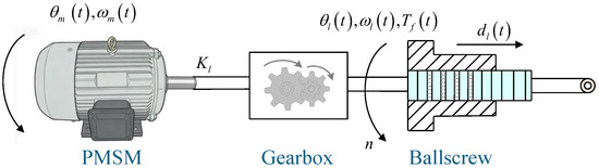
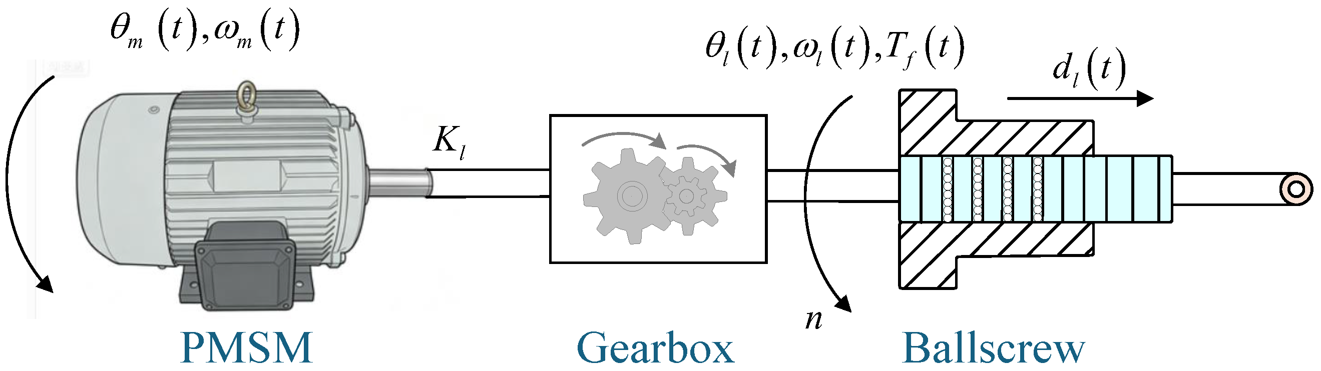
As illustrated in Figure 1, the considered EMA consists of a PMSM, a gear transmission stage, a ball-screw mechanism, and an aerodynamic load. The PMSM generates electromagnetic torque, which is transmitted through the gearbox and subsequently converted into linear motion by the ball-screw mechanism to drive the control surface.
Figure 1.
Schematic of the EMA.
The PMSM in the considered EMA is a three-phase AC machine. In the field-oriented control framework, the three-phase stator quantities are transformed into the stationary frame through the Clarke transformation and subsequently into the rotor-synchronous frame through the Park transformation [32,33]. Under the commonly adopted field-oriented control strategy with , the electromagnetic torque can be expressed as [34]. Since the inner current-loop dynamics are faster than the mechanical dynamics by a sufficient margin, they are neglected in the controller-oriented model, and the q-axis current is treated as the control input.
The state vector and control input are defined as
where and denote the load angular displacement and velocity, respectively; and denote the rotor angular displacement and velocity of the motor; and is the q-axis current. Combining the PMSM electromagnetic torque relation with the motor-side and load-side mechanical dynamics yields the following reduced-order EMA model [6]:
Here, n denotes the gear reduction ratio; is the equivalent torsional stiffness of the transmission shaft; and are the equivalent load inertia and motor inertia, respectively; and are the viscous damping coefficients; and denotes the motor torque constant. The lumped disturbance is defined as
where includes the external load torque, nonlinear friction effects, parameter perturbations, and unmodeled dynamics. In this work, the disturbance is assumed to be slowly varying, namely, . The system output is the load linear displacement , which can be denoted as
where is the ball-screw lead. The control objective is to make y track a prescribed reference trajectory despite the disturbance . According to (4), this objective can be equivalently reformulated as making track
The reference trajectory is assumed to be sufficiently smooth, and its required derivatives are bounded.
2.2. Feedback-Linearization Coordinate Transformation
As shown in (2), the disturbance enters the load-side dynamics, whereas the control input u acts on the motor-side dynamics. This constitutes a mismatched disturbance that cannot be directly compensated through the motor-side control input. Although conventional state-feedback controllers, such as linear quadratic regulators (LQRs), can stabilize the nominal EMA dynamics, they cannot directly resolve the problem of mismatched disturbance. To obtain a control-oriented representation with a matched total disturbance, an input–output feedback-linearization transformation is introduced. Following the standard input–output feedback-linearization procedure [20], we define the normal coordinates as
Under the assumption of slowly varying disturbance, namely, , the disturbed EMA model (2) can be transformed into
where
From (7), it is observed that the relative degree of the EMA system is , which equals the state dimension. Hence, no internal dynamics are introduced by the transformation.
Remark 1.
The disturbance ϵ is mismatched in the original EMA model (2) because it acts on the load-side acceleration equation, while the control input acts on the motor-side acceleration equation. After the feedback-linearization coordinate transformation, both u and ϵ appear in the fourth equation of (7). Therefore, the disturbance can be handled as a matched total disturbance in the normal-coordinate model. This transformation is the key reason for the subsequent observer-based disturbance compensation design.
2.3. Port-Hamiltonian Reformulation in the Transformed Coordinates
Based on the feedback-linearization coordinate transformation, the EMA dynamics have been rewritten as the fourth-order chain system (7). The transformed system possesses a regular input–output cascade structure, where the control input and the transformed disturbance act on the same highest-order channel. This property makes it possible to construct a port-Hamiltonian (PH) representation in the transformed coordinates. Compared with a conventional state-space description, the PH framework offers a clear characterization of the storage function, interconnection structure, and damping mechanism, which is beneficial for energy-shaping and damping-injection controller design. It should be emphasized that the port-Hamiltonian representation constructed here is control-oriented. The artificial quadratic storage function is defined in the feedback-linearized coordinates rather than the physical Hamiltonian of the EMA. Accordingly, the subsequent controller does not reshape the original mechanical energy through the classical IDA-PBC matching procedure. Instead, an IDA-PBC-inspired interconnection-and-damping assignment is performed on the transformed tracking dynamics.
To establish a Hamiltonian-oriented representation, the following quadratic storage function is selected as
where is a constant weighting matrix. Its gradient is given by
From (11), one obtains and . This representation shows that the transformed disturbance and the control input act through the same port in the normal coordinates.
Remark 2.
The port-Hamiltonian representation in (12) differs from the physical port-Hamiltonian model used in classical IDA-PBC. Since the design is carried out after the feedback-linearization coordinate transformation, is an artificial storage function rather than the kinetic and potential energy of the original EMA. Therefore, the formulation adopted in this work should be interpreted as an IDA-PBC-inspired energy-shaping representation in the transformed coordinates, rather than classical IDA-PBC based on physical-energy matching.
3. Feedback-Linearization-Assisted Observer-Based IDA-PBC Design
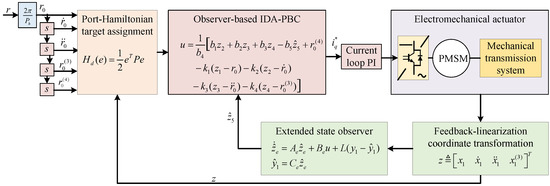
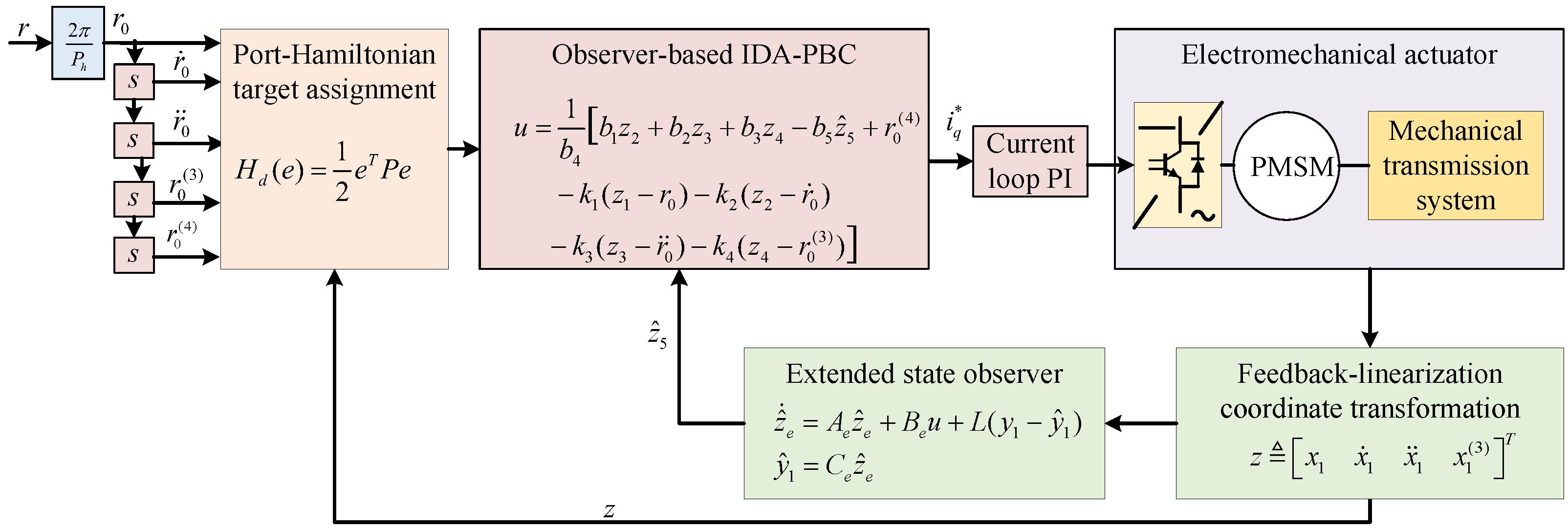
In this section, a feedback-linearization-assisted observer-based IDA-PBC method is developed for the EMA system with the schematic shown in Figure 2. First, an ESO is constructed for the normal-coordinate model (7). Second, based on the estimated disturbance, the closed-loop tracking-error dynamics are assigned to a desired dissipative port-Hamiltonian structure.
Figure 2.
Schematic of the proposed feedback-linearization-assisted observer-based IDA-PBC method.
3.1. Extended State Observer for Disturbance Estimation
To estimate the lumped disturbance , it is treated as an extended state . The augmented normal-coordinate model is
where and
The observability matrix of the pair is
Since , the pair is observable. The following ESO is designed:
where is the estimation of , while is the observer gain vector. The estimation error is . The observer error dynamics are
The observer gain can be selected explicitly using the Routh–Hurwitz criterion. The characteristic polynomial of is
where
According to the Routh–Hurwitz criterion, the observer error dynamics are asymptotically stable if , , , , and , where and are the corresponding Hurwitz determinants. For practical tuning, the desired observer polynomial can be assigned as with . Matching the coefficients yields
Hence, the observer gain can be tuned through the single parameter . A larger generally improves the convergence speed, but excessive values may increase sensitivity to measurement noise.
3.2. Port-Hamiltonian-Based Tracking Control
To achieve trajectory tracking, the reference vector is defined as The tracking error vector between the actual and desired states can be expressed as
The desired companion matrix is defined as
where are selected such that is Hurwitz. Let be a prescribed matrix. Since is Hurwitz, there exists a unique matrix satisfying
The desired Hamiltonian function is
The desired interconnection and damping matrices are assigned as
From (22), it follows that
Hence, and .
The relationship between the feedback gains and the desired port-Hamiltonian structure can be made explicit. Since , the target dynamics
are equivalent to
Hence,
Because the last row of is , the feedback gains are related to the desired interconnection and damping matrices through
where is the ith canonical basis vector. In the present design, the gains are first selected such that is Hurwitz. The matrix P is then obtained from the Lyapunov equation, after which and are determined accordingly. Therefore, the control gains and the desired port-Hamiltonian matrices are not independent design quantities but are linked through the prescribed closed-loop matrix .
Remark 3.
The high-order derivatives introduced in the feedback-linearized coordinates are not required to be directly measured in practical implementation. They can be obtained using numerical differentiation methods, such as the finite-difference method, or reconstructed using a high-order observer [35]. Therefore, the normal-coordinate states required by the controller can be generated online without introducing dedicated acceleration or higher-order derivative sensors.
Considering the disturbance estimation error , the desired error dynamics of the EMA can be equivalently represented as the following dissipative port-Hamiltonian target dynamics:
Note that in (31), the terms containing and compensate the known normal-coordinate dynamics and reference feedforward term, the term containing compensates the estimated transformed disturbance, and the terms containing assign the desired closed-loop tracking dynamics.
3.3. Stability Analysis
The closed-loop system consists of the observer-error subsystem and the tracking-error subsystem interconnected through the disturbance-estimation residual. The following stability analysis follows the standard composite Lyapunov and cascade-system stability framework [20,36], specialized here to the proposed observer-based EMA control system.
Theorem 1.
Under the assumption of slowly varying disturbance, the EMA tracking-error system under the ESO (15) and the observer-based IDA-PBC law (31) is globally exponentially stable.
Proof.
Since is observable, the observer gain L can be assigned such that is Hurwitz. Hence, for a prescribed matrix , there exists a unique matrix satisfying
The storage function for the observer error system is chosen as
Taking the derivative of along (16) gives
where denotes the minimum eigenvalue of , while is the 2-norm. Substituting (31) into (20) yields
Because and , the derivative of along (35) is
with . By the Cauchy–Schwarz and Young inequalities,
with . It follows from (36) and (37) that
The composite Lyapunov function is constructed as
where is a constant to be specified. Combining (34) and (38) yields
Choose such that
Then, there exists a constant
and hence,
Let . Since and , there exist constants and such that
Moreover, (43) implies that for some . Therefore, , which proves global exponential convergence of to the origin. Thus, both the tracking error and the observer estimation error converge exponentially to zero. □
Remark 4.
The assumption is introduced to facilitate the theoretical analysis and to establish exponential convergence of the nominal closed-loop error dynamics, rather than as a necessary condition for implementing the proposed controller. In practical operation, time-varying disturbances, parameter uncertainties, modeling errors, imperfect feedback linearization, and measurement noise may introduce additional perturbations into the tracking and observer error dynamics. Provided that these perturbations remain bounded, the exponential convergence to the origin is generally relaxed to boundedness of the tracking and estimation errors. Therefore, the exponential-stability result established above should be understood as a nominal result under the stated assumptions.
4. Illustrated Results and Discussions
To evaluate the performance of the feedback-linearization-assisted observer-based IDA-PBC method for the displacement control of the EMA, a simulation model is established in MATLAB/SIMULINK R2023b. The system parameters of the EMA are listed in Table 1. To ensure a fair comparison, a conventional proportional–integral–derivative (PID) controller, the fixed-time sliding-mode control (FTSMC) method, and the active disturbance rejection control (ADRC) are selected as benchmark controllers, with the control law shown in Table 2. The displacement-tracking performance and disturbance rejection capability of different control methods are evaluated under various operating conditions. Two typical reference trajectories, comprising step and sinusoidal signals, together with two representative external load disturbances, comprising step and sinusoidal torque disturbances, are considered in the simulations. These test scenarios are designed to investigate the dynamic response characteristics of the EMA system under both reference variations and external disturbances. Furthermore, the disturbance estimation results obtained from the ESO are presented to evaluate the capability of the proposed method in reconstructing unknown disturbance torque.
Table 1.
Parameters of the EMA system.
Table 2.
Control laws of the benchmark controllers.
4.1. Displacement Step Tracking Results
To investigate the disturbance rejection capability of the proposed method under a fixed displacement command, a step reference signal with an amplitude of is first considered. Two types of load torque disturbances, including a step disturbance and a sinusoidal disturbance, are respectively introduced at to analyze the control performance under abrupt and periodic disturbance conditions.
For the two disturbance scenarios, the displacement-tracking responses, tracking error curves, and disturbance estimation results obtained from the ESO are presented. The effectiveness of different control strategies in maintaining position accuracy and compensating external disturbances is evaluated based on the obtained simulation results.
4.1.1. Results Under a Step Torque Disturbance
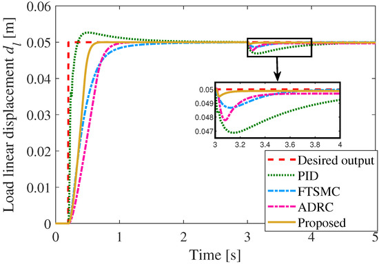
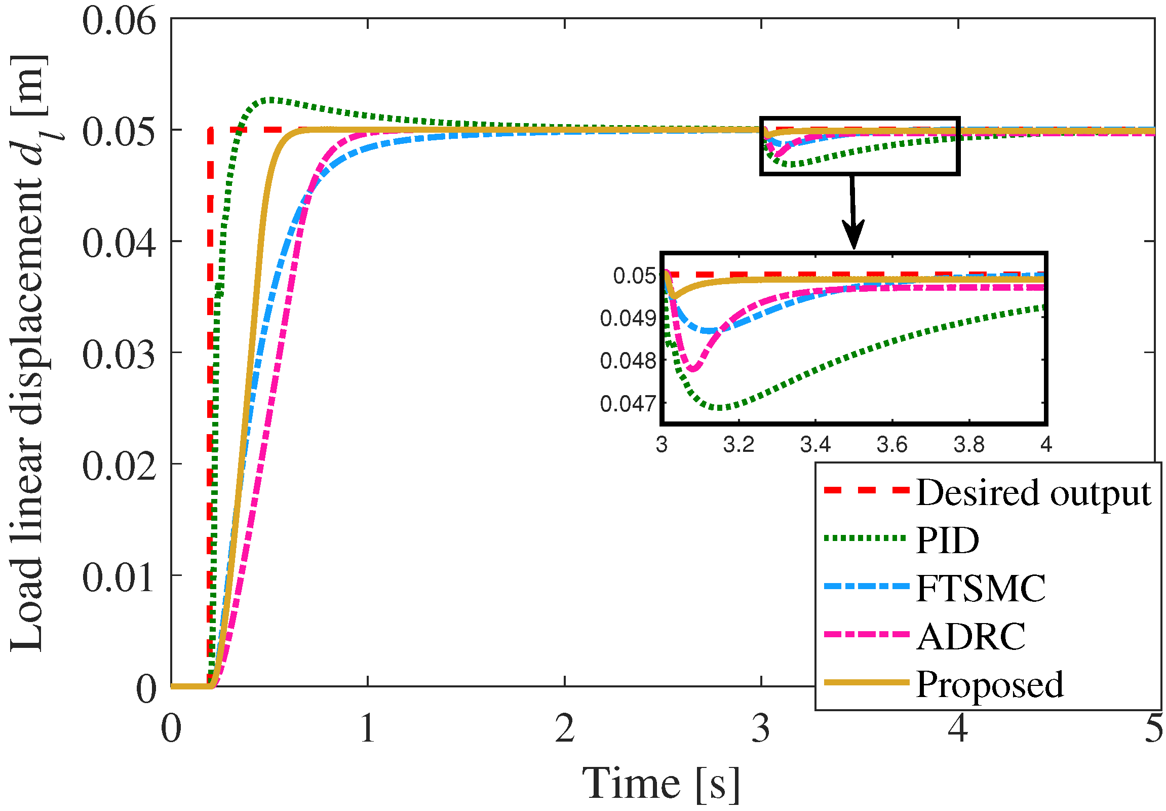
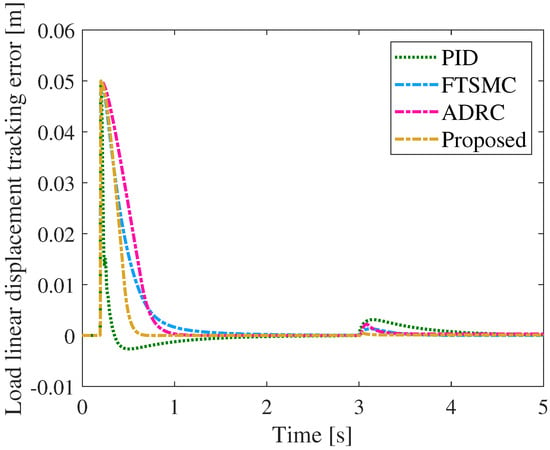
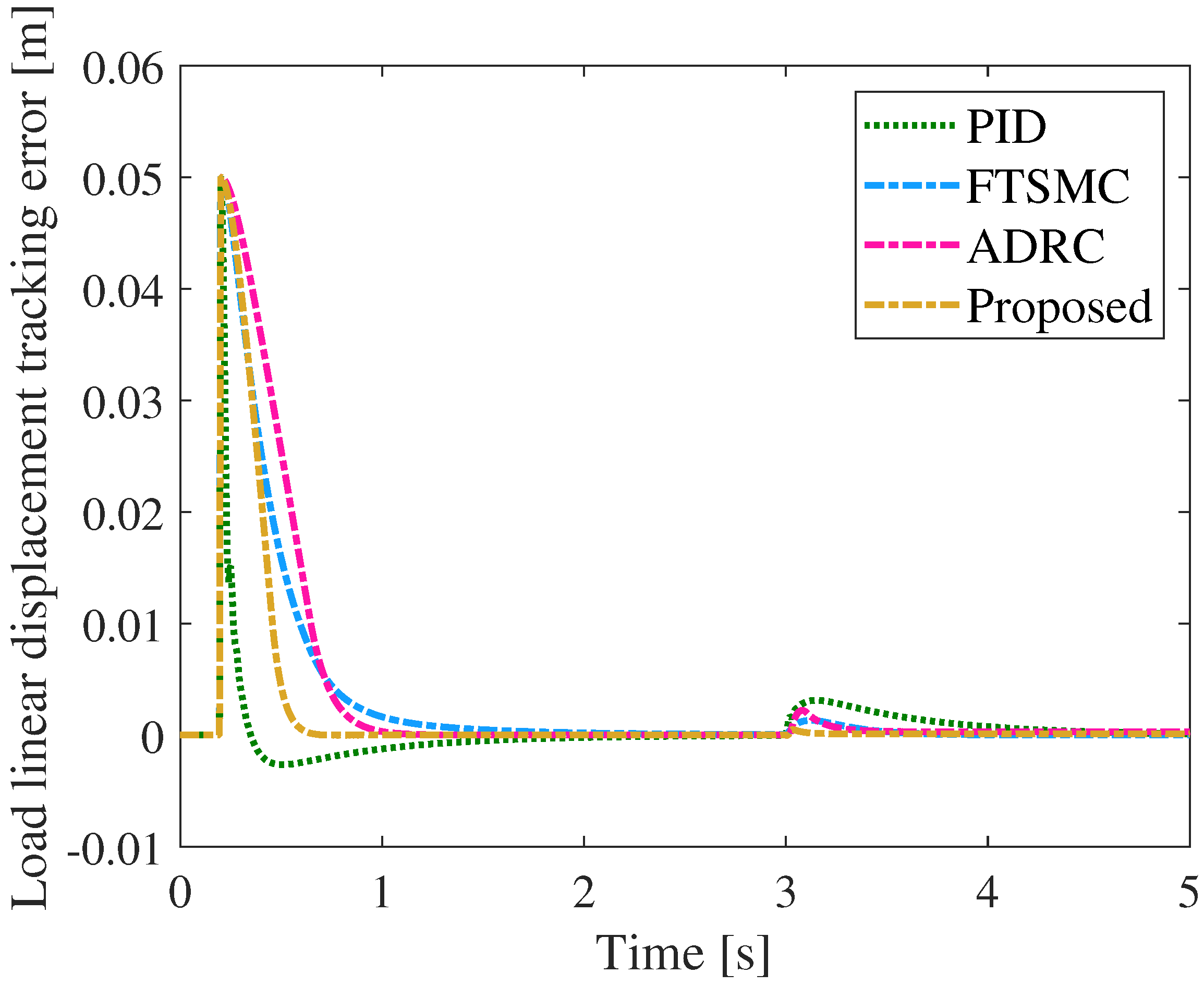
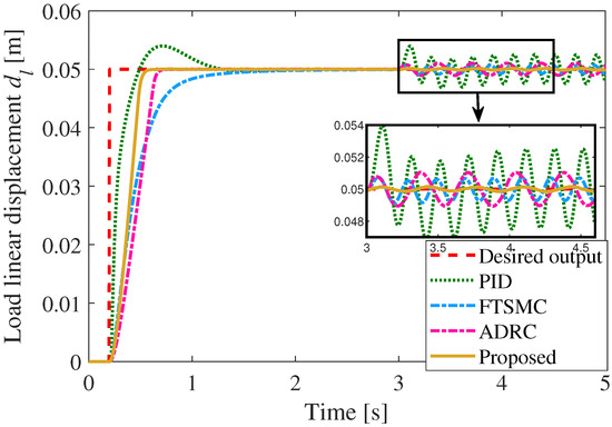
As shown in Figure 3 and Figure 4, the displacement-tracking responses and tracking errors of the PID, FTSMC, and proposed methods are compared under a step position command with a step load torque disturbance of . Before the disturbance is applied, all three controllers achieve satisfactory tracking performance with small displacement deviations, indicating that the closed-loop system maintains acceptable tracking accuracy under nominal conditions.
Figure 3.
Step tracking response curve comparison under step disturbance.
Figure 4.
Comparison results of step tracking errors under step disturbance.
When the step load disturbance is introduced at , different disturbance rejection performances can be observed among the three controllers. The PID controller exhibits the largest position deviation, with a maximum tracking error of , indicating that its tracking performance is more sensitive to abrupt load variations. The ADRC controller reduces the disturbance-induced deviation, with a maximum tracking error of . In comparison, the FTSMC method further reduces the disturbance-induced deviation, and the maximum tracking error decreases to . This result indicates that the FTSMC and ADRC methods provide improved robustness against external disturbances compared with the conventional PID controller.
Compared with the benchmark methods, the proposed method achieves a smaller tracking deviation and a smoother recovery process after the disturbance occurrence. The maximum tracking error is limited to , which is reduced by approximately , , and compared with the PID, FTSMC, and ADRC methods. Moreover, the displacement response curve shows that the proposed method returns to the reference position more rapidly after the disturbance is applied, while maintaining a smaller fluctuation amplitude during the recovery process. The tracking error curve further demonstrates that the error variation of the proposed method remains within a smaller range without obvious oscillations. These results indicate that, under the tested step disturbance condition, the proposed method can effectively reduce the position deviation caused by external load variations and improve the disturbance rejection performance of the EMA system.
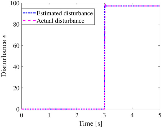
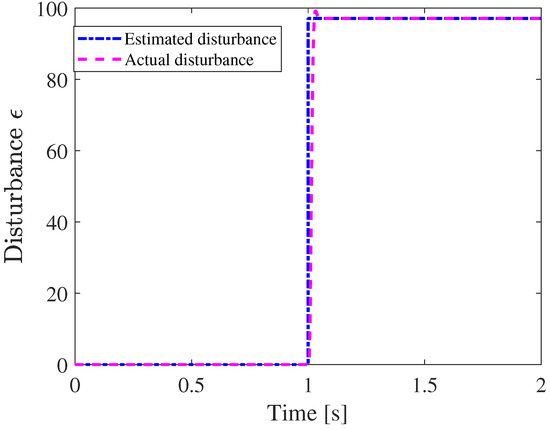
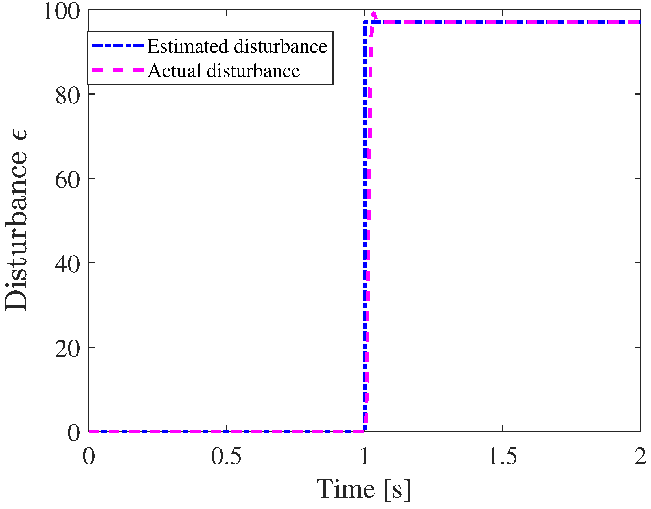
Figure 5 presents the disturbance estimation results of the ESO under the step load disturbance condition. Before the disturbance is introduced, both the actual disturbance and the estimated disturbance remain close to zero, indicating that the ESO can accurately characterize the disturbance-free condition. When the step disturbance is applied at , the actual disturbance rapidly increases to , and the estimated disturbance responds accordingly with a peak value of . Due to the abrupt variation of the external disturbance, a transient estimation deviation appears during the initial observation process. However, the estimated disturbance rapidly converges to the actual disturbance within approximately , and the two curves remain highly consistent thereafter. The results demonstrate that the designed ESO can effectively reconstruct the external disturbance under the tested step disturbance condition and provide reliable disturbance estimation information for the proposed controller.
Figure 5.
Results of the proposed observer with step disturbance under the step command.
4.1.2. Results Under a Sinusoidal Torque Disturbance
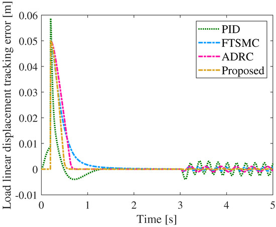
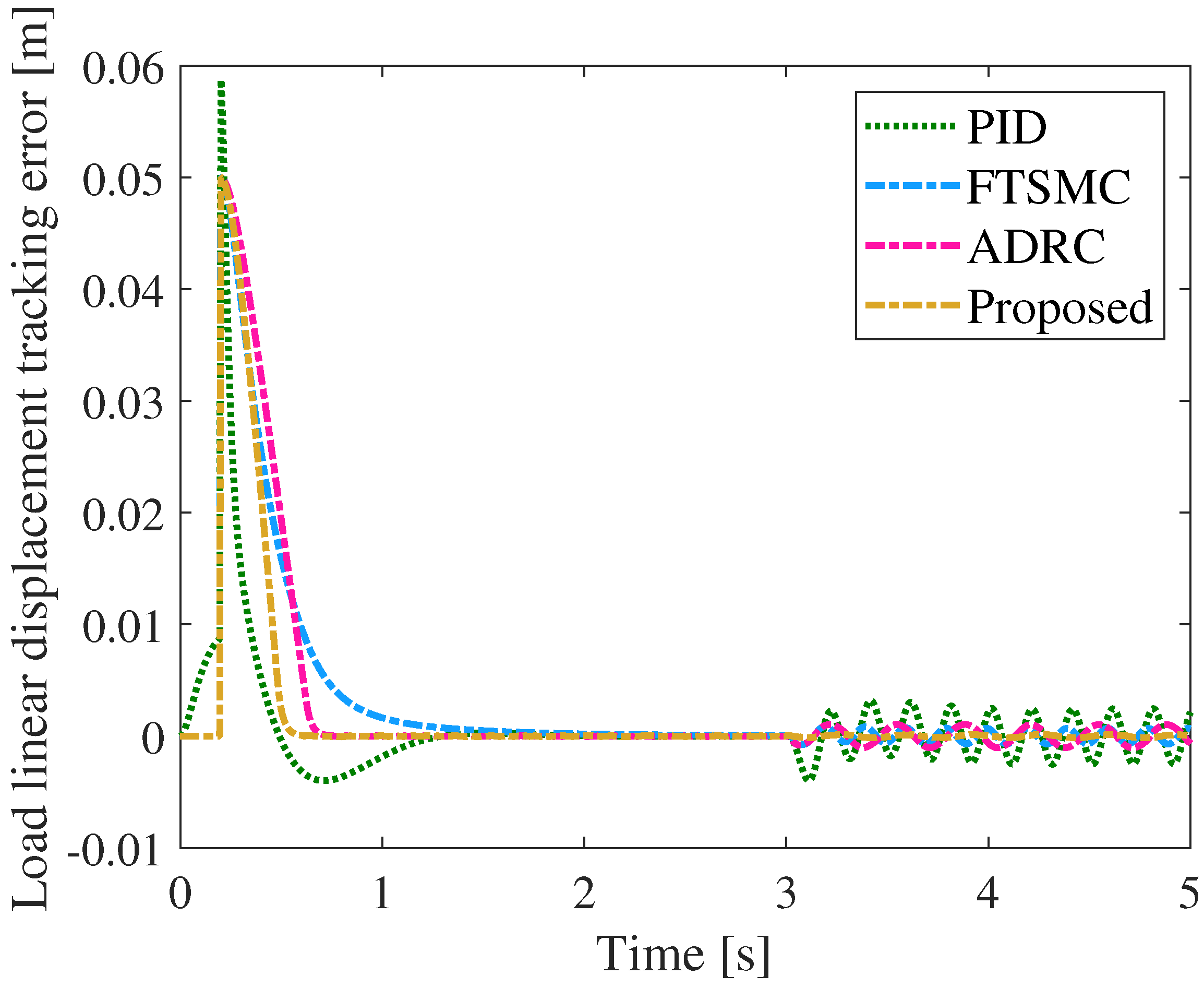
Figure 6 and Figure 7 present the displacement-tracking responses and tracking errors of the PID, FTSMC, and proposed methods under a step reference command with a sinusoidal load disturbance. Before the disturbance is introduced, all three controllers maintain accurate tracking of the reference position, indicating that the closed-loop system achieves satisfactory tracking performance under nominal conditions.
Figure 6.
Step tracking response curve comparison under sinusoidal disturbance.
Figure 7.
Comparison results of step tracking errors under sinusoidal disturbance.
When the sinusoidal load disturbance is applied at , different disturbance rejection characteristics can be observed among the three control methods. The PID controller exhibits relatively large displacement fluctuations caused by the periodic disturbance, resulting in a maximum tracking error of . This indicates that the conventional PID controller has a limited ability to maintain position accuracy under time-varying load disturbances. In comparison, the ADRC controller reduces the disturbance-induced deviation, with a maximum tracking error of . The FTSMC method further reduces the disturbance-induced position deviation, with the maximum tracking error decreased to , demonstrating improved robustness against periodic disturbances.
Compared with the benchmark methods, the proposed method achieves a more stable position response with smaller tracking fluctuations under the sinusoidal disturbance condition. The maximum tracking error is limited to only , which is reduced by approximately , , and compared with the PID, ADRC, and FTSMC methods, respectively. As observed from the tracking error curve, the proposed method maintains a smaller error amplitude after the disturbance is introduced, without apparent sustained oscillations. These results indicate that, under the tested sinusoidal disturbance condition, the proposed method can effectively attenuate the influence of periodic load variations and maintain higher displacement-tracking accuracy.
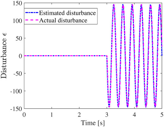
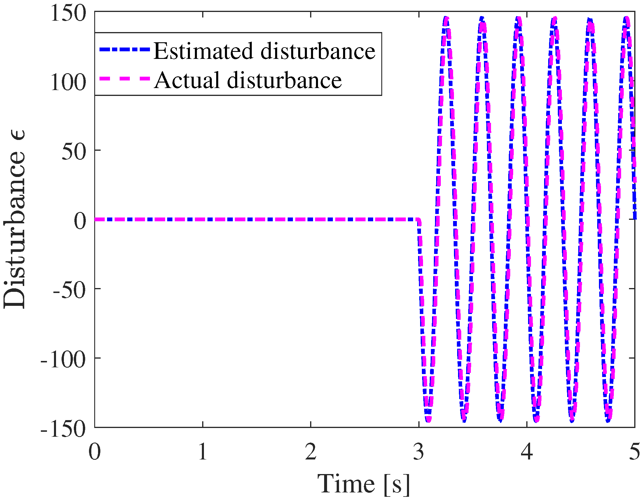
Figure 8 illustrates the disturbance estimation results of the ESO under the sinusoidal load disturbance condition. As the external disturbance varies periodically, the estimated disturbance follows the variation trend of the actual disturbance , and the two curves maintain good consistency throughout the dynamic process. The estimated disturbance accurately reflects the periodic characteristics of the external load torque, without obvious phase lag during the disturbance variation. Although a small estimation deviation exists during the dynamic tracking process, the estimated disturbance continuously follows the actual disturbance variation. The results indicate that the designed ESO is capable of dynamically estimating time-varying load disturbances and providing effective disturbance information for the proposed controller under the tested sinusoidal disturbance condition.
Figure 8.
Results of the proposed observer with sinusoidal disturbance under the step command.
4.2. Displacement Sine Curve Tracking Results
To further evaluate the control performance of the proposed method under dynamic displacement-tracking conditions, comparative simulations are conducted with a sinusoidal reference signal. The amplitude and frequency of the reference displacement are set to and , respectively. Step and sinusoidal disturbance torques are introduced separately to investigate the displacement-tracking performance of the PID controller, the FTSMC method, the ADRC algorithm, and the proposed method.
4.2.1. Step Torque Disturbance Results
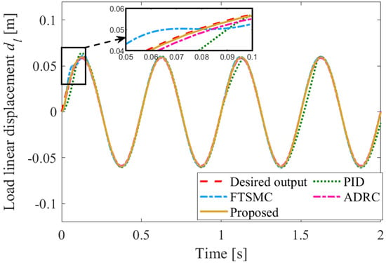
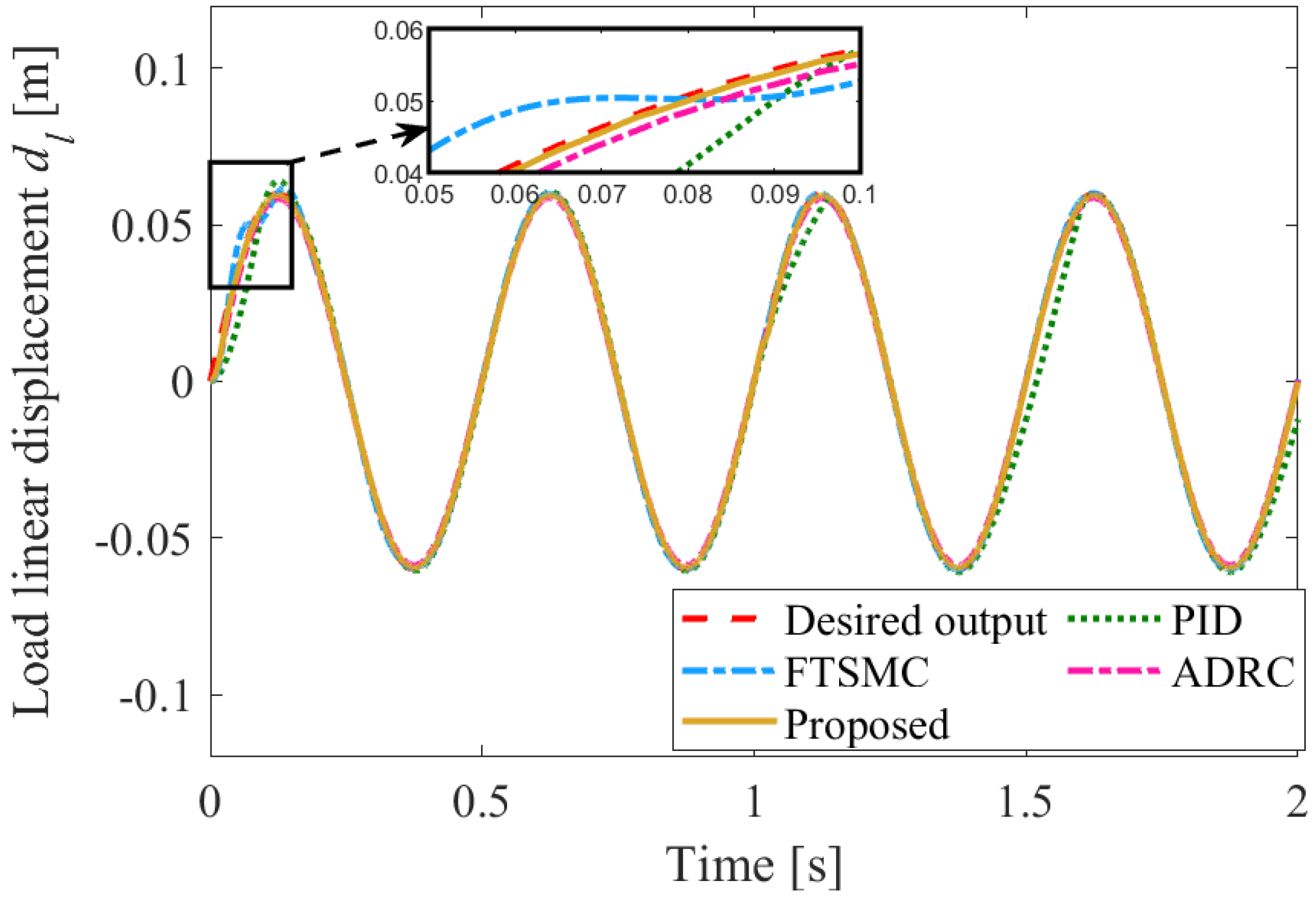
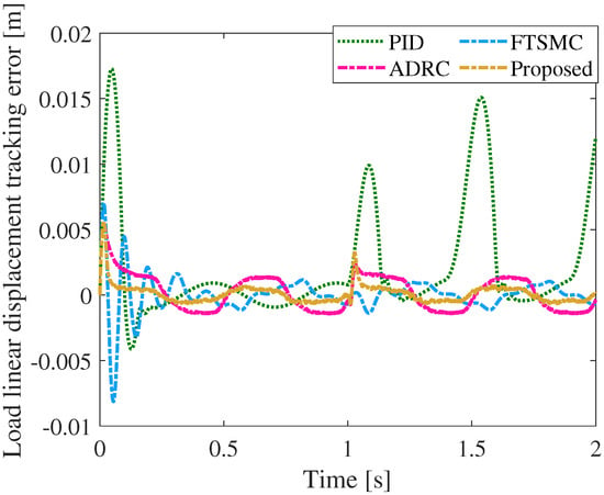
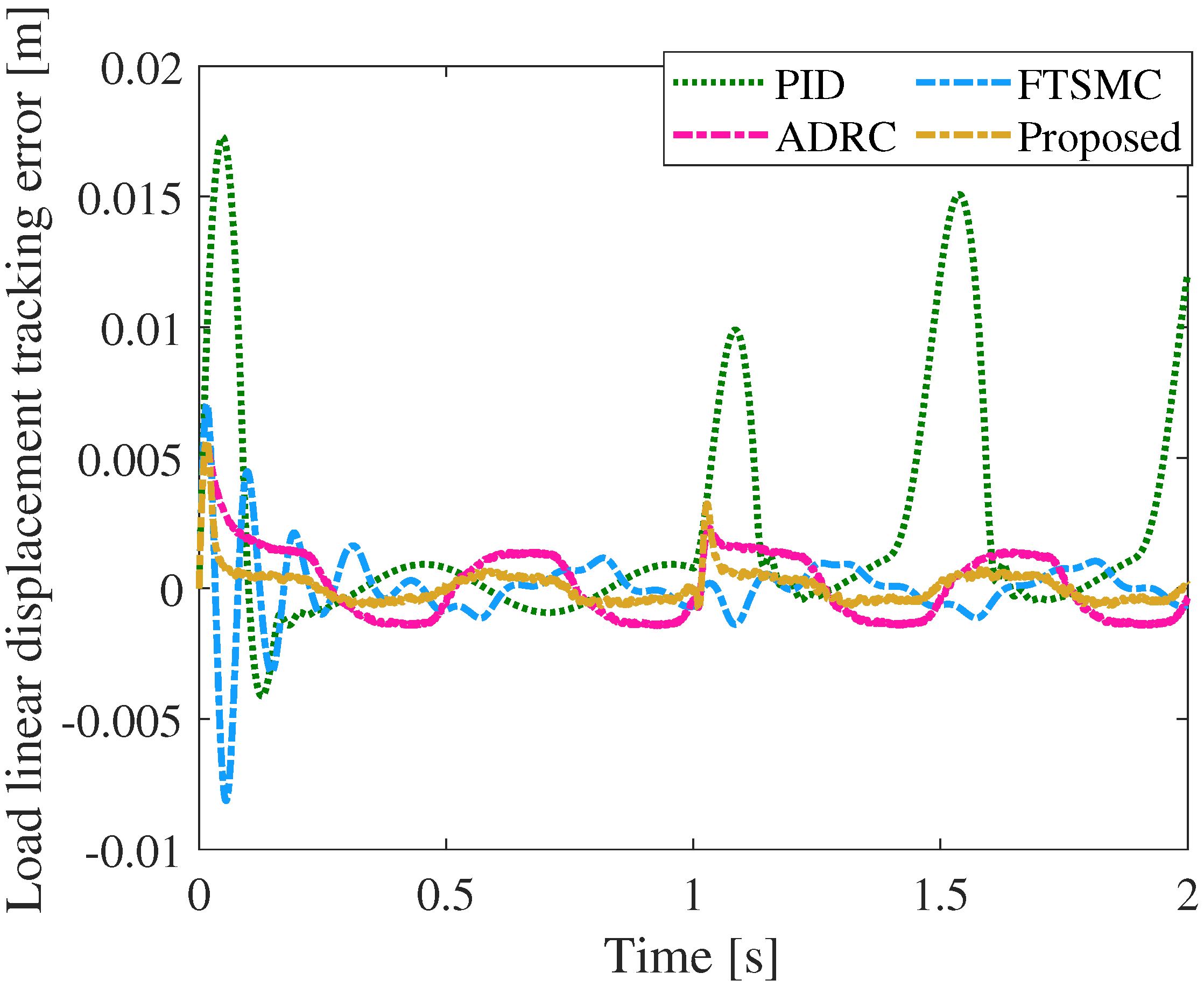
Figure 9 and Figure 10 present the displacement-tracking responses and tracking errors of the three control methods under a sinusoidal displacement reference. Before the external disturbance is applied, all methods can follow the periodic reference trajectory. Compared with the PID and FTSMC methods, the proposed method exhibits a closer agreement between the output response and the reference trajectory, with smaller tracking deviations.
Figure 9.
Sinusoidal tracking response curve comparison under step disturbance.
Figure 10.
Comparison results of step tracking errors under step disturbance.
When the step disturbance torque is introduced at , different error responses are observed among the three controllers. The PID controller suffers from a considerable tracking deviation, and the maximum tracking error reaches . In comparison, the ADRC, FTSMC, and proposed methods reduce the disturbance-induced error variation, with the maximum tracking errors limited to . Furthermore, the error curve of the proposed method exhibits smoother variations during the subsequent periodic tracking process, maintaining smaller tracking error fluctuations after the disturbance occurrence.
The above results demonstrate that, under the combined condition of a sinusoidal displacement reference and a step disturbance torque, the proposed method can maintain stable displacement-tracking performance and reduce the influence of abrupt load variations on the dynamic tracking process.
Figure 11 presents the disturbance estimation results of the ESO under the sinusoidal displacement reference with a step disturbance torque. After the step disturbance is introduced at , the estimated disturbance responds rapidly to the variation in the actual disturbance and gradually reaches the steady state. As observed from the estimation curves, the ESO accurately captures the change in the amplitude of the step disturbance, with only a short transient deviation during the disturbance transition. Subsequently, the estimated disturbance remains consistent with the actual disturbance. The result indicates that the designed ESO possesses a fast disturbance response capability during dynamic displacement tracking and can effectively reconstruct abrupt load disturbances.
Figure 11.
Results of the proposed observer with step disturbance under the sinusoidal command.
4.2.2. Sinusoidal Torque Disturbance Results
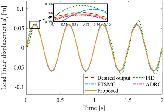
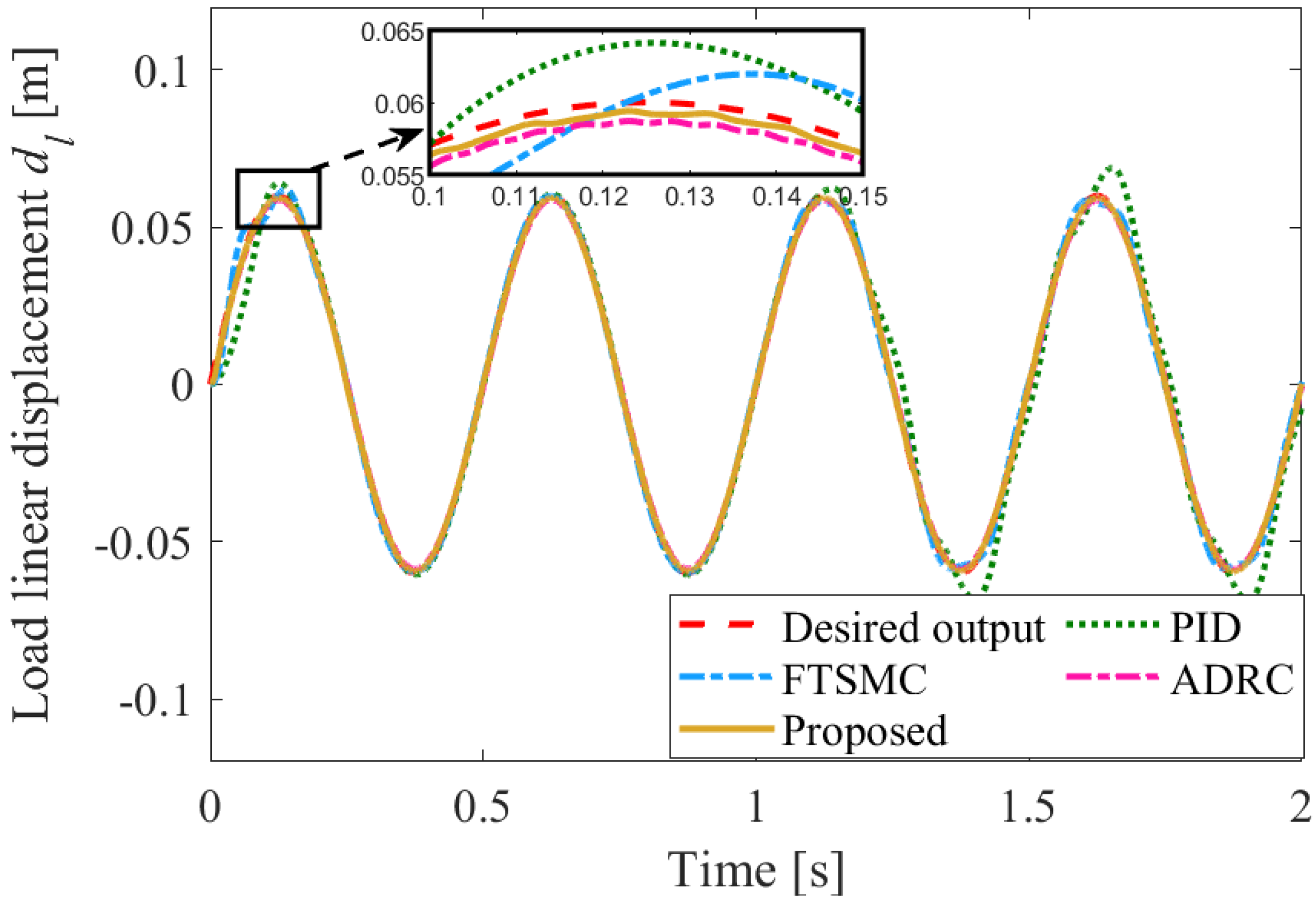
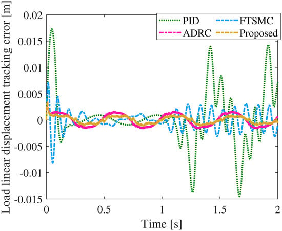
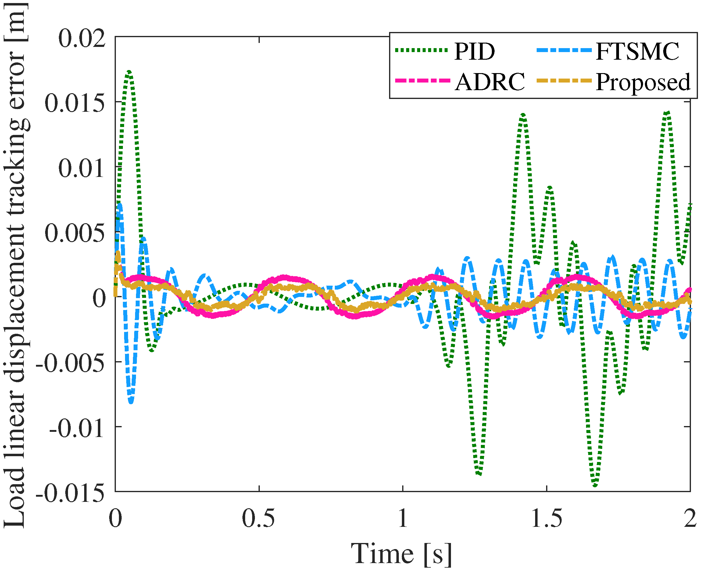
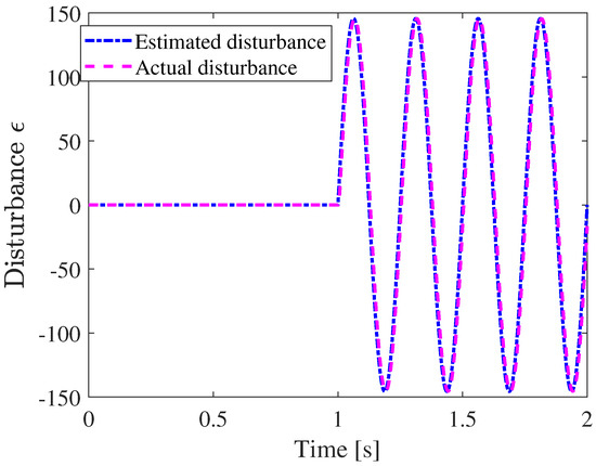
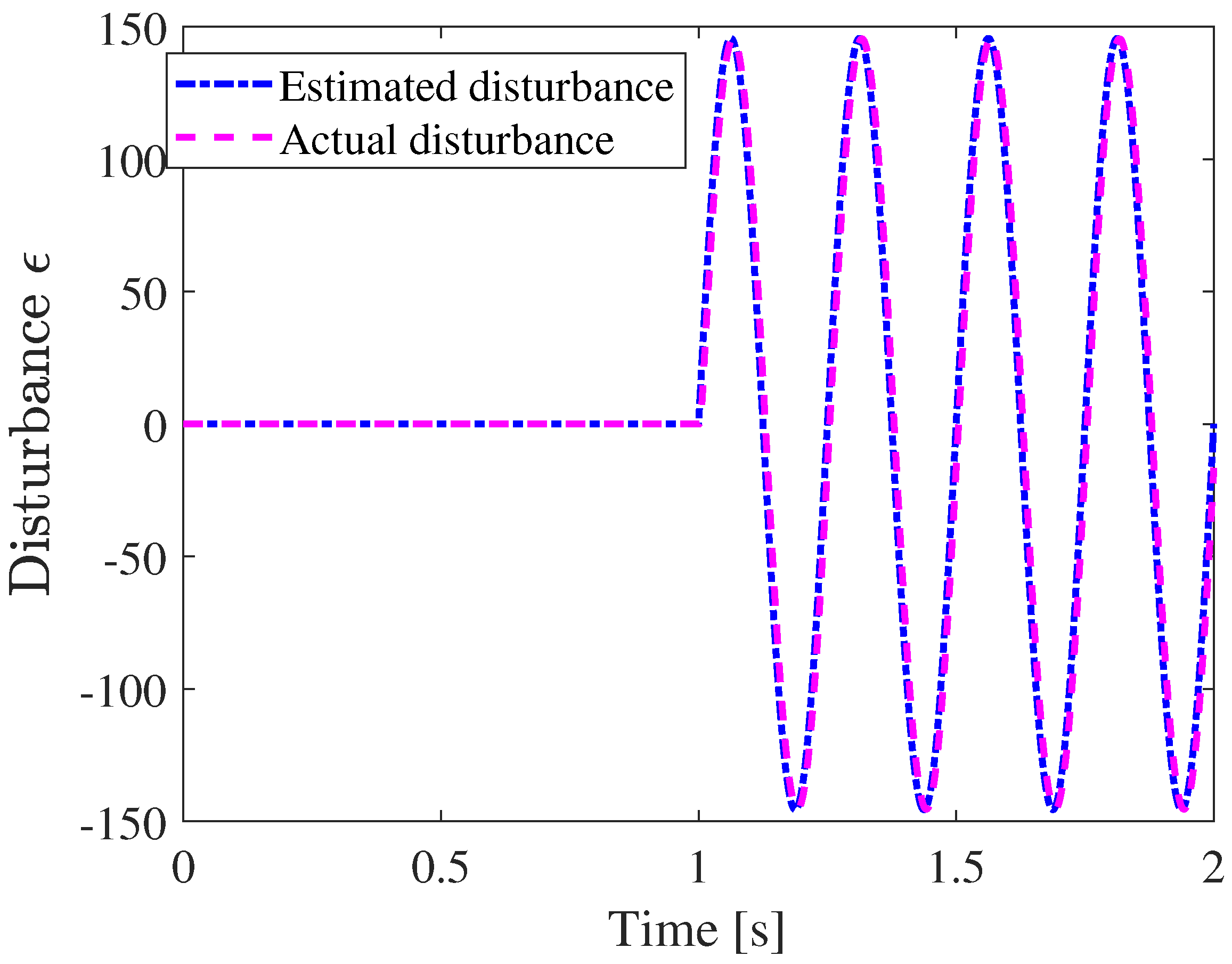
To further investigate the system response to time-varying disturbances during dynamic displacement tracking, a sinusoidal disturbance torque is introduced at . Figure 12 and Figure 13 present the tracking responses and tracking errors of different control methods under a sinusoidal displacement reference, while Figure 14 shows the disturbance estimation results of the ESO under the same condition.
Figure 12.
Sinusoidal tracking response curves under sinusoidal disturbance.
Figure 13.
Tracking errors of different methods with sinusoidal disturbance under the sinusoidal command.
Figure 14.
Results of the proposed observer with sinusoidal disturbance under the sinusoidal command.
As illustrated in Figure 12 and Figure 13, the dynamic responses and tracking errors of the three control methods during sinusoidal displacement tracking, where a sinusoidal disturbance torque is introduced at . Before the disturbance occurs, all methods achieve satisfactory tracking of the reference trajectory. After the disturbance is applied, the PID controller exhibits apparent periodic tracking deviations, resulting in larger error fluctuations. In comparison, the ADRC and FTSMC methods reduce the disturbance-induced error variations, while the proposed method maintains smaller tracking error fluctuations and a closer agreement between the output response and the reference trajectory. As shown in Figure 14, the estimated disturbance variable of the ESO remains consistent with the actual disturbance variable, accurately reflecting the dynamic variation characteristics of the disturbance term.
To quantitatively evaluate the servo tracking performance of different control methods, three error indices, including the maximum absolute error (MAE), integral absolute error (IAE), and root mean square error (RMSE), are adopted for comparison. The corresponding results are summarized in Table 3. It is observed that the proposed method achieves smaller error indices under different disturbance conditions compared with the PID, ADRC, and FTSMC methods. These results further demonstrate the improved displacement-tracking accuracy of the proposed method under disturbed operating conditions. To further summarize the performance characteristics observed in the simulations, the main advantages and limitations of the tested methods are presented in Table 4.
Table 3.
Quantitative comparison of tracking performance and control action under different displacement references and disturbance conditions.
Table 4.
Advantages and limitations of the tested control methods based on the simulation results.
4.3. Ablation Study
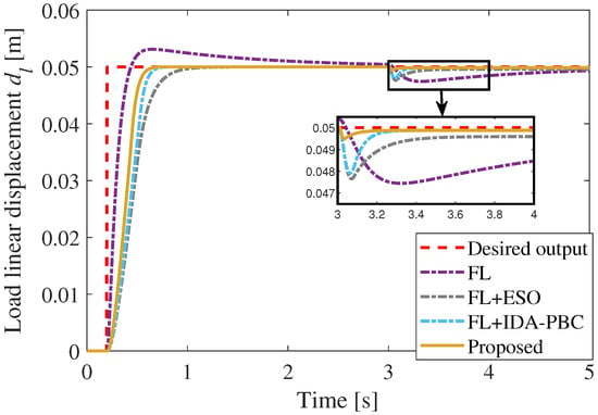
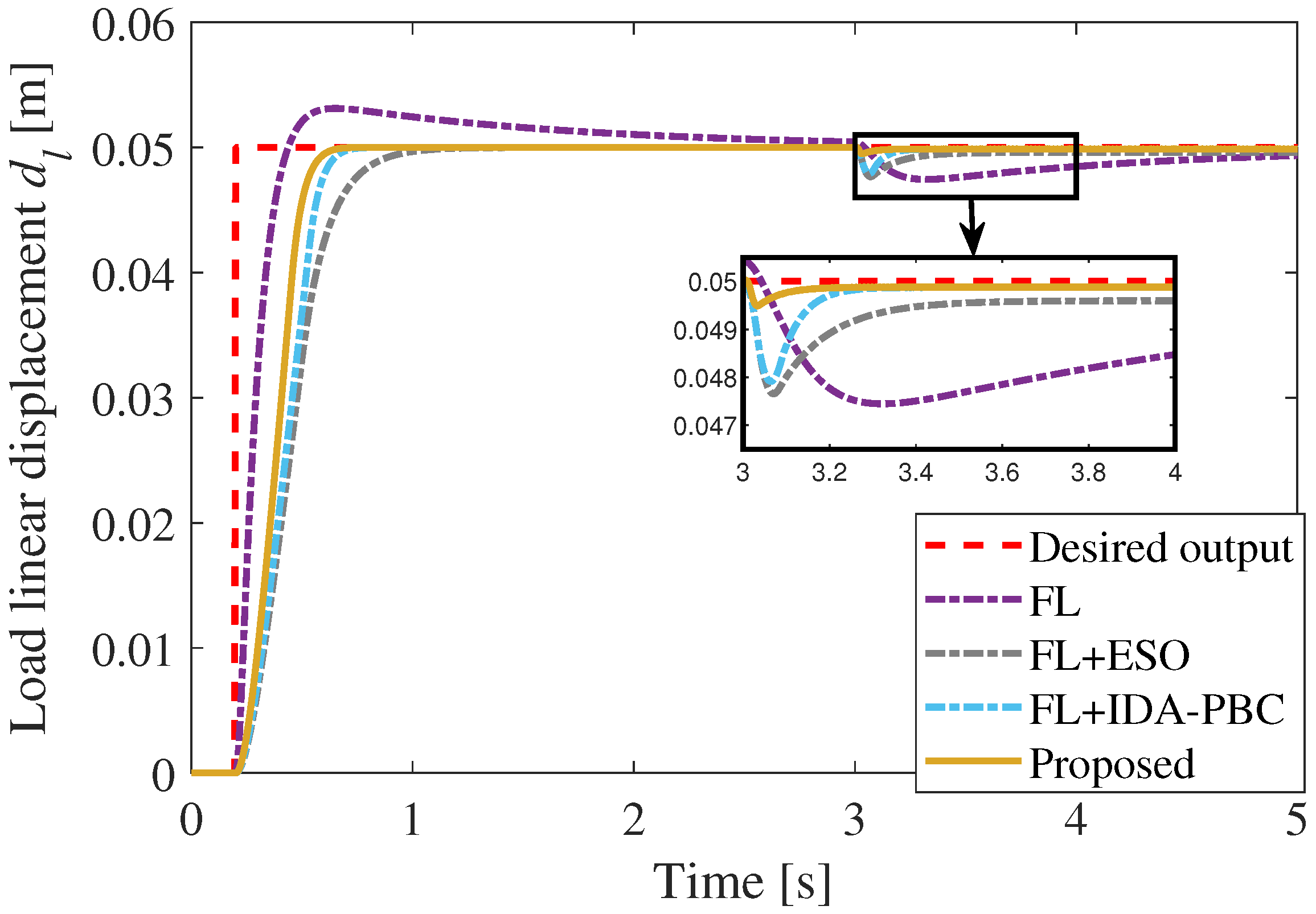
To clarify the respective roles of the main components in the proposed control framework, four controller configurations are considered under identical operating conditions: feedback linearization (FL), FL combined with the ESO (FL+ESO), FL combined with the IDA-PBC-inspired design (FL+IDA-PBC), and the complete proposed controller.
The comparison in Figure 15 reveals distinct performance characteristics among the different configurations. The FL controller exhibits a relatively large transient deviation and a slow recovery after the load disturbance is introduced. After incorporating the ESO, the disturbance-induced deviation is noticeably reduced, indicating the effectiveness of online disturbance estimation and compensation. The FL+IDA-PBC configuration also improves the transient response by reshaping the closed-loop dynamics through interconnection and damping assignment. By integrating both mechanisms, the complete proposed controller provides the best overall tracking performance and disturbance rejection. The results therefore confirm that the ESO and the IDA-PBC-inspired design play complementary roles in improving the disturbance rejection and transient characteristics of the feedback-linearized EMA system.
Figure 15.
Ablation study of the proposed control framework under a step load disturbance.
4.4. Robustness Analysis
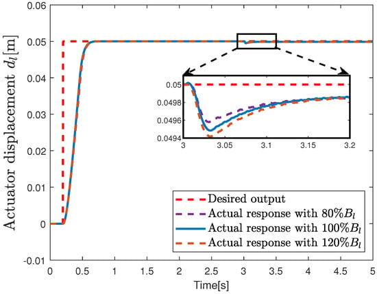
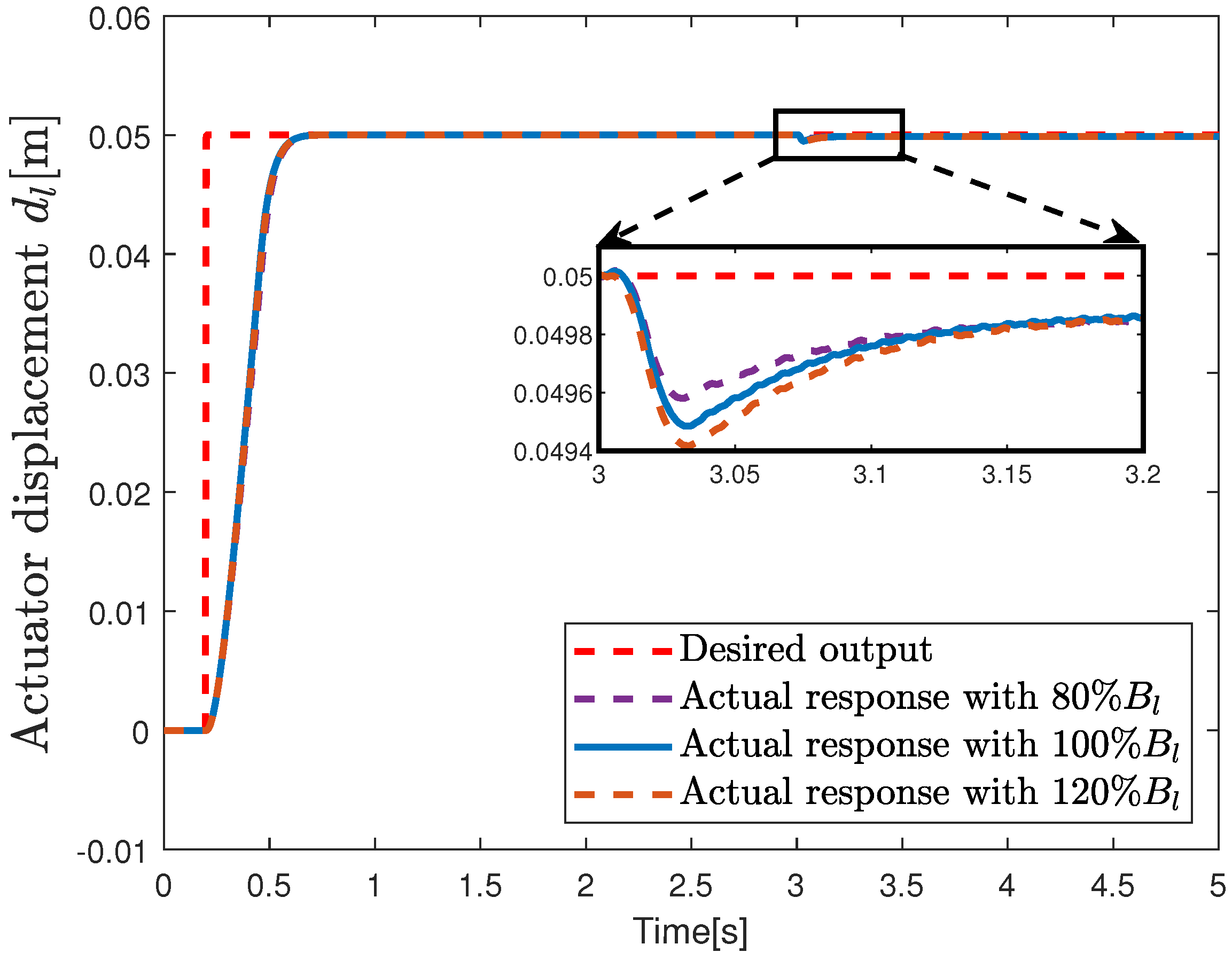
Since the proposed controller involves the EMA model parameters in the feedback-linearization process, the influence of parameter uncertainty on the closed-loop performance is further investigated. The load-side damping coefficient is selected as a representative uncertain parameter and is varied to , , and of its nominal value. During the robustness tests, the nominal value of is retained in the controller, while all controller and observer gains remain unchanged.
As shown in Figure 16, variations in mainly result in slight differences in the transient response after the load disturbance is introduced. For all three parameter settings, the closed-loop system remains stable and the actuator displacement rapidly recovers toward the desired value. No apparent oscillation or significant deterioration in tracking performance is observed when varies within of its nominal value. These results indicate that the proposed method maintains satisfactory tracking and disturbance rejection performance under the considered load-side damping uncertainty.
Figure 16.
Step response of the EMA system under different parameter perturbations.
5. Conclusions
This paper developed a feedback-linearization-assisted observer-based IDA-PBC method for an EMA subject to load-side lumped disturbances. A fourth-order normal-coordinate model is first derived, through which the mismatched load-side disturbance in the original mechanical coordinates is transformed into a matched term acting on the same channel as the control input. An ESO is then designed for the augmented normal-coordinate model, and an IDA-PBC tracking law is constructed by assigning a desired Hamiltonian function and the corresponding interconnection and damping matrices. The closed-loop tracking-error dynamics were shown to admit a dissipative port-Hamiltonian representation, and a composite Lyapunov proof established global exponential stability under the assumption of slowly varying disturbance. The resulting framework combines disturbance-channel reshaping, observer-based compensation, and energy-shaping control, making it suitable for high-precision EMA servo tracking. Future work will focus on extending the proposed framework to more realistic EMA dynamics by explicitly considering nonlinear effects such as friction and backlash. Hardware-in-the-loop testing and experimental validation under realistic aerodynamic load profiles will also be pursued.
Author Contributions
Conceptualization, X.X. and Q.O.; methodology, X.X., X.C. and Q.O.; formal analysis, X.X. and X.C.; software, X.X. and B.L.; validation, X.X., B.L. and Z.Z.; writing—original draft preparation, X.X.; writing—review and editing, X.C. and Q.O.; supervision, Z.Z.; project administration, Z.Z. All authors have read and agreed to the published version of the manuscript.
Funding
This research received no external funding.
Institutional Review Board Statement
Not applicable.
Informed Consent Statement
Not applicable.
Data Availability Statement
The data supporting the reported results are available from the corresponding author upon reasonable request.
Acknowledgments
The authors acknowledge the support of the College of Automation Engineering, Nanjing University of Aeronautics and Astronautics.
Conflicts of Interest
The authors declare no conflicts of interest.
References
- Annaz, F.Y.; Kaluarachchi, M.M. Progress in Redundant Electromechanical Actuators for Aerospace Applications. Aerospace 2023, 10, 787. [Google Scholar] [CrossRef] [Scilit]
- Han, J. From PID to active disturbance rejection control. IEEE Trans. Ind. Electron. 2009, 56, 900–906. [Google Scholar] [CrossRef] [Scilit]
- Fang, Q.; Zhou, Y.; Ma, S.; Zhang, C.; Wang, Y.; Huangfu, H. Electromechanical actuator servo control technology based on active disturbance rejection control. Electronics 2023, 12, 1934. [Google Scholar] [CrossRef] [Scilit]
- Bai, Y.; Hu, J.; Yao, J. Adaptive neural network output feedback robust control of electromechanical servo system with backlash compensation and disturbance rejection. Mechatronics 2022, 84, 102794. [Google Scholar] [CrossRef] [Scilit]
- Su, Z.; Shi, W.; Duan, J.; Xu, L.; Zhou, M. Double-loop compensated active disturbance rejection control of electromechanical servo system based on composite disturbance observer. Expert Syst. Appl. 2025, 266, 126155. [Google Scholar] [CrossRef] [Scilit]
- Xiao, X.; Zhen, Z.; Sun, H. Disturbance observer-based fixed-time sliding-mode control for electromechanical actuators. Actuators 2026, 15, 247. [Google Scholar] [CrossRef] [Scilit]
- Sun, H.; Jiang, J.; Xiao, X. Fuzzy active disturbance rejection control for electro-mechanical actuator based on feedback linearization. Actuators 2025, 15, 18. [Google Scholar] [CrossRef] [Scilit]
- Xiong, S.; Cheng, X.; Ouyang, Q.; Lv, C.; Xu, W.; Wang, Z. Disturbance compensation-based feedback linearization control for air rudder electromechanical servo systems. Asian J. Control 2025, 27, 2255–2265. [Google Scholar] [CrossRef] [Scilit]
- Zhou, C.; Wang, B.; Liu, K.; Ren, K. Active disturbance rejection control of permanent magnet synchronous motor based on RPLESO. Energies 2024, 17, 3025. [Google Scholar] [CrossRef] [Scilit]
- Zhu, M.; Ni, H.; Sun, H.; Wang, J. A cascaded linear active disturbance rejection control-based multi-stage model predictive control for permanent magnet synchronous motor. IEICE Electron. Express 2024, 21, 20240137. [Google Scholar] [CrossRef] [Scilit]
- Gao, P.; Pan, H. An enhanced switching active disturbance rejection controller for speed control of permanent magnet synchronous motor. IEICE Electron. Express 2023, 20, 20230476. [Google Scholar] [CrossRef] [Scilit]
- Wang, X.; Xiang, Y.; Qu, C.; Han, F.; Xu, D. Single closed-loop active disturbance rejection control strategy of permanent magnet synchronous motor based on compensation function. IEICE Electron. Express 2024, 21, 20240281. [Google Scholar] [CrossRef] [Scilit]
- Li, T.; Zhao, Y.; Hou, L. Adaptive sliding mode control with disturbance observer for speed regulation system of permanent magnet synchronous motor. IEEE Access 2023, 11, 17021–17030. [Google Scholar] [CrossRef] [Scilit]
- Liu, Y.C. Disturbance-observer-based second-order sliding-mode position control for permanent-magnet synchronous motors: A continuous twisting algorithm-based approach. Energies 2024, 17, 2974. [Google Scholar] [CrossRef] [Scilit]
- Liu, R.; Liu, Y.; Wang, C. Disturbance-observer-based fixed-time prescribed performance control for permanent magnet synchronous motor under friction disturbance. Int. J. Adapt. Control Signal Process. 2025, 39, 2637–2649. [Google Scholar] [CrossRef] [Scilit]
- Huo, Z.; Ping, Z.; Jia, Y.; Hui, J.; Huang, Y.; Lu, J.G. Disturbance rejection of PMSM speed servo system: An adaptive observer approach. Control Theory Technol. 2025, 23, 640–649. [Google Scholar] [CrossRef] [Scilit]
- Hu, S.; Ren, X.; Zheng, D. Disturbance observer-based finite-time optimal synchronization control for multi-motor driving servo systems. Int. J. Control Autom. Syst. 2024, 22, 72–83. [Google Scholar] [CrossRef] [Scilit]
- Li, M.; Zhang, J.; Li, S.; Wu, F.; Zhang, T.; Zhou, P. Disturbance-observer-based adaptive finite-time dynamic surface control for PMSM with time-varying asymmetric output constraint. Asian J. Control 2023, 25, 3752–3775. [Google Scholar] [CrossRef] [Scilit]
- Peng, J.; Yao, M. Overview of predictive control technology for permanent magnet synchronous motor systems. Appl. Sci. 2023, 13, 6255. [Google Scholar] [CrossRef] [Scilit]
- Khalil, H.K. Nonlinear Systems, 3rd ed.; Prentice Hall: Upper Saddle River, NJ, USA, 2002. [Google Scholar]
- Meng, X.; Yu, H.; Zhang, J.; Xu, T.; Wu, H.; Yan, K. Disturbance observer-based feedback linearization control for a quadruple-tank liquid level system. ISA Trans. 2022, 122, 146–162. [Google Scholar] [CrossRef] [Scilit] [PubMed]
- Yang, Y.; Cui, Y.; Qiao, J.; Zhu, Y. Adaptive periodic-disturbance observer based composite control for SGCMG gimbal servo system with rotor vibration. Control Eng. Pract. 2023, 132, 105407. [Google Scholar] [CrossRef] [Scilit]
- Ortega, R.; van der Schaft, A.; Maschke, B.; Escobar, G. Interconnection and damping assignment passivity-based control of port-controlled Hamiltonian systems. Automatica 2002, 38, 585–596. [Google Scholar] [CrossRef] [Scilit]
- Ortega, R.; Spong, M.W.; Gomez-Estern, F.; Blankenstein, G. Stabilization of a Class of Underactuated Mechanical Systems via Interconnection and Damping Assignment. IEEE Trans. Autom. Control 2002, 47, 1218–1233. [Google Scholar] [CrossRef] [Scilit]
- Serra, F.M.; De Angelo, C.H. IDA-PBC Controller Design for Grid Connected Front End Converters under Non-Ideal Grid Conditions. Electr. Power Syst. Res. 2017, 142, 12–19. [Google Scholar] [CrossRef] [Scilit]
- Barman, S.; Samanta, S.; Mishra, J.P.; Roy, P.; Roy, B.K. Design and Implementation of an IDA-PBC for a Grid Connected Inverter Used in a Photovoltaic System. IFAC-PapersOnLine 2018, 51, 680–685. [Google Scholar] [CrossRef] [Scilit]
- Belkhier, Y.; Achour, A.; Bures, M.; Ullah, N.; Bajaj, M.; Zawbaa, H.M.; Kamel, S. Interconnection and damping assignment passivity-based non-linear observer control for efficiency maximization of permanent magnet synchronous motor. Energy Rep. 2022, 8, 1350–1361. [Google Scholar] [CrossRef] [Scilit]
- Azzi, M.; Baghli, L.; Jamshidpour, E.; Thounthong, P.; Takorabet, N. Enhanced interconnection and damping assignment passivity-based control for PM synchronous motors. Glob. Energy Interconnect. 2025, 8, 657–667. [Google Scholar] [CrossRef] [Scilit]
- Macchelli, A. A discrete-time formulation of nonlinear distributed-parameter port-Hamiltonian systems. IEEE Control Syst. Lett. 2024, 8, 802–807. [Google Scholar] [CrossRef] [Scilit]
- Sarkar, A.; Scherpen, J.M.A. Structure-preserving generalized balanced truncation for nonlinear port-Hamiltonian systems. Syst. Control Lett. 2023, 174, 105501. [Google Scholar] [CrossRef] [Scilit]
- Zenfari, S.; Laabissi, M.; Achhab, M.E. Observer design for a class of discrete port Hamiltonian systems. J. Control Autom. Electr. Syst. 2023, 34, 963–970. [Google Scholar] [CrossRef] [Scilit]
- Clarke, E. Circuit Analysis of A-C Power Systems; John Wiley & Sons: New York, NY, USA, 1943. [Google Scholar]
- Park, R.H. Two-Reaction Theory of Synchronous Machines—Generalized Method of Analysis—Part I. Trans. Am. Inst. Electr. Eng. 1929, 48, 716–727. [Google Scholar] [CrossRef] [Scilit]
- Blaschke, F. The Principle of Field Orientation as Applied to the New TRANSVECTOR Closed-Loop Control System for Rotating-Field Machines. Siemens Rev. 1972, 34, 217–220. [Google Scholar]
- Huang, J.; Zhang, M.; Ri, S.; Xiong, C.; Li, Z.; Kang, Y. High-Order Disturbance-Observer-Based Sliding Mode Control for Mobile Wheeled Inverted Pendulum Systems. IEEE Trans. Ind. Electron. 2020, 67, 2030–2041. [Google Scholar] [CrossRef] [Scilit]
- Padulo, L.; Arbib, M.A. System Theory: A Unified State-Space Approach to Continuous and Discrete Systems; W. B. Saunders: Philadelphia, PA, USA, 1974. [Google Scholar]

Disclaimer/Publisher’s Note: The statements, opinions and data contained in all publications are solely those of the individual author(s) and contributor(s) and not of MDPI and/or the editor(s). MDPI and/or the editor(s) disclaim responsibility for any injury to people or property resulting from any ideas, methods, instructions or products referred to in the content. |
© 2026 by the authors. Licensee MDPI, Basel, Switzerland. This article is an open access article distributed under the terms and conditions of the Creative Commons Attribution (CC BY) license.