


Abstract
DC motors are widely used in mechatronic systems; however, their performance degrades significantly in the presence of nonlinear mechanical loads, parameter variations and sensing uncertainties. This paper proposes three control strategies (i.e., PID, optimal, and hybrid controllers) for discrete-time DC motor systems to overcome the disturbances caused by nonlinear mechanical loads and parameter variations. Optimal control of nonlinear discrete-time systems is formally characterized by the Hamilton–Jacobi–Bellman (HJB) equation, whose analytical solution is generally intractable. To address this challenge, a learning-based optimal control strategy based on the Heuristic Dynamic Programming (HDP) framework is developed to approximate the HJB equation, supported by a formal convergence proof. For that purpose, Neural Networks (NNs) are employed to approximate both the cost function and the optimal control policy, enabling near-optimal performance with manageable computational complexity. Although the resulting optimal control achieves fast convergence, it may introduce overshoot and steady-state offset under nonlinear disturbances. To address this limitation, a hybrid control framework is proposed, where nonlinear optimal corrections are integrated with the robustness and adaptability of Proportional–Integral–Derivative (PID) control through error-dependent gating and gain-scheduling mechanisms. A structured evaluation framework is conducted, including nominal analysis, motor-parameter stress testing across nine nonlinear scenarios, controller-design sensitivity analysis, and stochastic measurement-noise assessment under filtered sensing conditions. Results demonstrate that the hybrid controller preserves transient speeds within 5–10% of the optimal controller while effectively eliminating overshoot and steady-state offset under nominal conditions. The hybrid design reduces the accumulated tracking error by more than 95% compared to the optimal controller, while incurring only negligible additional control effort. Under aggressive supply-sag disturbances, the hybrid controller significantly limits peak deviation and reduces accumulated tracking error by over 90%, while maintaining comparable control cost. Overall, the hybrid framework provides a convergence-proven and practically deployable control solution that combines near-optimal convergence speed with robust, overshoot-free performance for intelligent motion-control and robotics applications.
1. Introduction
The Direct Current (DC) motor is one of the most essential actuators in modern mechatronic systems. It drives robots, electric vehicles, aerospace mechanisms, and renewable-energy platforms due to its high torque-to-inertia ratio, compact size, and ease of control [1,2]. Its significance continues to grow in applications that demand both high performance and energy efficiency [3].
Nonlinear effects significantly limit the reliability and accuracy of DC motors. Among these, Coulomb and viscous friction are the most commonly modeled; however, real systems also exhibit more complex velocity-dependent phenomena, such as the Stribeck effect, which degrades low-speed accuracy [4]. Belt-drive tension and backlash can cause oscillations under variable loads [5], while aerodynamic-related losses (e.g., ventilation and cooling airflow) become important in high-speed and lightweight motor designs [6]. Such nonlinearities deform the torque–speed characteristics, increase steady-state errors, and degrade transient performance. Precise modeling and compensation of these frictional effects are therefore crucial for achieving effective controller design [7,8].
The Proportional–Integral–Derivative (PID) controller continues to dominate industrial practice because of its simplicity, interpretability, and reliability [9,10]. Various enhancements have been proposed, including adaptive tuning, metaheuristic optimization, and intelligent gain scheduling [11]. For example, adaptive PID and fractional-order PID strategies have been investigated for DC drives subject to elastic coupling and parameter uncertainties, demonstrating improved disturbance rejection and tracking performance under load variations [12]. These studies highlight the continued relevance of adaptive PID-based designs for improving robustness in nonlinear operating conditions. Despite these advances, PID-based structures may still experience performance degradation in strongly nonlinear operating regions or under rapidly varying loads, particularly in discrete-time implementations where parameter variations and nonlinear effects interact.
Beyond PID-based strategies, advanced nonlinear control methods, including Model Predictive Control (MPC) [13], sliding-mode control [14], feedback linearization, and predefined-time stabilization [15], have also been explored. These approaches provide improved disturbance rejection and enhanced transient performance, although their practical implementation may require accurate system modeling, increased computational resources, or careful tuning to balance robustness and complexity [16,17].
Optimal control of nonlinear systems is formally characterized by the Hamilton–Jacobi–Bellman (HJB) equation. Due to its intractability for nonlinear systems, Approximate Dynamic Programming (ADP) and neural-network-based methods have been developed to approximate the value function and optimal policy [18]. Learning-based approaches now represent an active research direction. Neural networks support robust output-feedback control [19], inverse-system compensation in Brushless DC (BLDC) drives [20], and hybrid fuzzy–neural controllers [21]. These methods approximate unknown nonlinearities and adapt to variable operating conditions, offering greater flexibility compared to traditional designs. Reinforcement Learning (RL) techniques have been further applied to DC motor control, including adaptive PI/PID enhancement [22,23], actor–critic speed regulation [24,25,26], and learning-based control strategies for mechatronic systems [27]. These methods aim to improve adaptability and performance without requiring exact system models.
More recently, hybrid structures integrating RL with classical PID controllers have been proposed. For instance, residual reinforcement learning strategies combine PID control with an additive learning-based correction term, typically implemented as an additive combination of the PID control action and a reinforcement learning-based correction term [28]. Such approaches enhance adaptability under disturbances by allowing RL to compensate for modeling errors and environmental variations. In many reported implementations, the learning component is integrated at the signal level through additive or weighted blending with the classical controller output, without a clear structural distinction between stability assurance and performance-oriented learning components. Furthermore, robustness evaluation is frequently conducted under limited disturbance scenarios, leaving open questions regarding performance consistency under combined nonlinear effects and parameter variations in discrete-time implementations.
Taken together, the existing literature demonstrates substantial progress in adaptive, nonlinear, and learning-based DC motor control. Despite these advances, discrete-time nonlinear optimal control formulations for DC motors supported by formal convergence analysis remain relatively limited. Moreover, structured integration of optimal control with robustness-enhancing mechanisms, validated under multiple interacting nonlinear stress scenarios, is less commonly addressed.
To address these aspects, this work proposes a structured control framework for discrete-time DC motor systems with nonlinear loads, in which a convergence-supported optimal controller is complemented by a dedicated mechanism for robustness and transient enhancement. The main contributions of this work are summarized as follows
- Development of a discrete-time HDP-based optimal controller with formal convergence analysis of the derived optimal control law.
- Design of a hybrid control architecture that integrates PID and optimal control components through error-dependent gating and gain scheduling while preserving the learned policy parameters.
- Comprehensive robustness evaluation framework including motor-parameter stress testing, controller-design sensitivity analysis, and stochastic measurement-noise assessment under filtered sensing conditions.
To verify effectiveness, comprehensive simulation study is conducted, including nominal analysis and a sensitivity evaluation across nine parameter scenarios. Three controllers are compared: a tuned conventional PID controller, as a baseline, a learning-based optimal controller, and a hybrid controller. Results consistently show that the optimal controller accelerates convergence and reduces cumulative error, whereas the hybrid design achieves overshoot-free operation with the most favorable error profile at negligible additional cost.
The remainder of this paper is organized as follows. Section 2 develops the discrete-time mathematical model of the DC motor with nonlinear mechanical loads. Section 3 formulates the three control strategies, including the conventional PID controller, the learning-based HDP optimal controller, and the proposed hybrid PID–optimal architecture with gating and gain scheduling mechanisms. Section 4 presents the numerical simulation framework and comparative evaluation, including nominal performance analysis, motor-parameter robustness assessment, controller-design sensitivity analysis, and robustness evaluation under stochastic measurement noise. Section 5 concludes the paper and outlines future research directions. Appendix A provides the formal convergence proof of the NN-based HDP algorithm, while the Tables in Appendix A report detailed robustness and sensitivity results.
2. Mathematical Model of DC Motor with Nonlinear Loads
In this section, the discrete-time mathematical model of a DC motor with nonlinear load that incorporates both Coulomb and viscous friction is introduced. The model is then formulated in an input-affine, state-nonlinear structure, making it well-suited to facilitate the development of learning-based optimal control and hybrid control strategies.
2.1. DC Motor Model
The standard armature circuit of a permanent magnet DC motor (refer to Figure 1) can be expressed by the following dynamics:
where is the armature inductance, is the armature resistance, is the armature current, is the Back Electromotive Force (EMF) constant, is the shaft angular velocity, is the applied control terminal voltage. By assuming that the armature inductance, , can be neglected and the electrical time constant is significantly smaller than the mechanical time constant due to the faster response of the electrical dynamics, Equation (1) can be simplified to
Figure 1.
Equivalent armature circuit of a permanent magnet DC motor.
Note that, since electrical dynamics evolve much faster than mechanical dynamics, the armature inductance, , is neglected without significant loss of accuracy. This assumption is commonly adopted in DC motor modeling to simplify control design [29]. The mechanical dynamics of the motor, considering the torque produced and the opposing load torques, can be formulated by
where is the rotor moment of inertia, is the torque constant, and represents the total load torque opposing the motor’s motion. By substituting the expression for the armature current, introduced in Equation (2), into Equation (3), the following expression can be obtained
Equation (4) captures the interplay between the electrical input and the mechanical response, highlighting the influence of load torques on the motor’s acceleration [29]. The complete continuous-time dynamics of a DC motor, combining the electrical and mechanical subsystems in Equations (1) and (3), respectively, can be expressed in state-space form as follows
where and . This formulation captures the interdependence of the electrical control input, u(t), and the system states, and .
2.2. Nonlinear Mechanical Load Model
In many real-world systems, nonlinear mechanical loads arise because physical interactions between moving parts do not follow ideal or linear laws. Such loads occur when the relationship between torque and speed is not proportional. They typically involve complex dynamics such as Coulomb friction, viscous damping, backlash, stiction, or variable inertia, making system behavior unpredictable and challenging to model and control. Accurate identification and compensation of these nonlinearities are essential for achieving high-performance control in mechatronic and motion systems. At low motor speeds, Coulomb friction becomes dominant, introducing discontinuous behavior near zero velocity that strongly affects stability and control accuracy. Hence, the total mechanical load torque can be represented as a function of motor speed, . One example of a nonlinear mechanical load that includes both Coulomb and viscous friction components is expressed as
where is the Coulomb (i.e., static) friction torque, is the viscous friction (i.e., damping) coefficient, is the nonlinear load constant, and is the signum function. This discontinuous nonlinearity mainly influences low-speed behavior, introducing non-smooth dynamics near zero velocity.
2.3. Discrete-Time Nonlinear Input-Affine Model Formulation
From Equation (4), it is clear that DC motor with a nonlinear mechanical load can be expressed in an input-affine form as follows
where
Equations (8)–(10) show that DC motor dynamics with a nonlinear mechanical load exhibit an input-affine nonlinear structure, where the control input, , appears linearly, while the system nonlinearity arises from the state-dependent mechanical load torque, . This structure is particularly important because it facilitates the development of various control techniques such as optimal, adaptive, robust, and reinforcement learning control, while still capturing the realistic nonlinear behavior of the mechanical load.
To enable real-time digital implementation and learning-based optimal control design, the continuous-time model in Equations (5) and (6) is discretized using the forward Euler approximation with a sampling period, , where the state variables are defined as and where is the discrete time index. From Equations (5) and (6), the discretized model can now be derived as
Although the armature inductance, , is omitted in the continuous-time derivation for analytical clarity as in Equation (2), the discrete-time formulation used for implementation retains the full model, including the inductance term in Equations (11) and (12). The omission of the armature inductance, , therefore serves only to simplify the analytical presentation and is not applied in controller design or simulation.
The adopted discrete-time model preserves the input-affine nonlinear structure of the original continuous-time system, which is essential for controller synthesis and stability analysis. The linear dependence on the control input facilitates implementation, while the nonlinear state dependence enables accurate representation of mechanical load nonlinearities.
Section 3 formulates the control strategies based on this unified discrete-time state-space model defined in Equations (11) and (12). All controllers are implemented and evaluated using the same full-order plant, ensuring modeling consistency and a fair performance comparison.
3. Controllers Formulation
Control design is a key element in ensuring stable and robust speed regulation in DC motors when operating under nonlinear load conditions. In this work, three control strategies were investigated and compared: (i) a Proportional–Integral–Derivative (PID) controller, (ii) an optimal controller formulated using quadratic cost weights, and (iii) a hybrid controller that merges the structured performance of PID with the adaptive features of the optimal scheme. The main control objective is to maintain the motor speed close to its constant desired reference under nonlinear disturbances such as Coulomb and viscous friction. All control laws are developed and implemented on the discrete-time nonlinear state-space model defined in Equations (11) and (12).
3.1. PID Controller
The PID controller remains one of the most widely applied control schemes in electric drives due to its simplicity and ease of implementation [30]. For a constant desired speed, , the discrete- time speed error, , is defined as
The PID controller regulates the motor speed , while the underlying plant dynamics follow the full discrete-time state model defined in Equations (11) and (12). The control input of the discrete standard PID law is expressed as
where , and are the proportional, integral, and derivative gains, respectively. The integral and derivative terms of the speed error are defined as
where is the sampling period. The gains tuning was performed iteratively to minimize overshoot and steady-state error while maintaining acceptable rise and settling times. For consistency and fair comparison, the PID controller is implemented in its standard form, without anti-windup compensation, feedforward action, or additional filtering. This enables a direct performance comparison with the proposed optimal and hybrid control strategies.
3.2. Learning-Based Optimal Controller
In discrete-time optimal control, the HJB equation provides a formal characterization of the optimal solution; however, its computational intractability for nonlinear systems necessitates the use of HDP approaches. The design of an optimal controller for nonlinear discrete-time systems therefore requires a unified framework that explicitly relates the system dynamics, the cost function, and the approximation method used to compute the optimal value function, as closed-form analytical solutions are generally unavailable. Within this framework, NNs are employed to approximate the value function, while learning-based strategies iteratively refine the control policy. Accordingly, the following subsections present the problem formulation, the HDP-based NN architecture, and the iterative HDP algorithm that ensures convergence to an approximate solution.
3.2.1. Problem Formulation and Control Objective
The DC motor dynamics, described in Equations (11) and (12), form an input-affine nonlinear discrete system, introduced in Equation (8), which can be written as
where the discrete state vector ∈ represents the armature current and motor angular speed. The function f ∈ characterizes the internal nonlinear dynamics of the DC motor system, which arise mainly from the load torque term, , as shown in Equation (7). Meanwhile ∈ represents the input influence matrix associated with the control input voltage u ∈
. The objective is to find an approximation for the optimal control policy, , using NN for the system given in Equations (11) and (12) that minimizes the cost function, , which is defined as [31]
where and are positive definite matrices. The cost function integrates both state deviation, , and control policy, u, serving as the quadratic cost minimized by the optimal controller. Together, they provide a complementary and consistent basis for comparing controllers that differ in their trade-offs between accuracy and control effort. The optimal control policy is given as [31]
and hence, the optimal cost function, , becomes [31]
To determine the optimal control policy , the expression in (20) must be solved. However, solving (20) is not straightforward. In [24], the HDP algorithm is employed to compute the optimal cost function associated with the HJB equation, under the assumption that exact solutions for both and are available. In practice, obtaining such exact solutions is difficult and often infeasible. Consequently, NN-based algorithms are utilized to approximate both the cost function and the control policy, thereby yielding approximate solutions to (19) and (20).
3.2.2. NN Approximation-Based HDP Algorithm
As stated earlier, the approximation of the optimal cost and corresponding policy (i.e., solving the HJB equation represented in Equation (20)) can be done using HDP. The next step is to specify the NN structure and the tuning method required to ensure convergence. It is important to emphasize that the choice of tuning method plays a critical role in guaranteeing stability and convergence. Equation (20) is solved iteratively following the procedure in [24]. The algorithm begins with the initial assumption that the initial value of the cost function, , is set to zero, after which a control policy is computed. The HDP scheme then alternates between a sequence of control policies, , determined by
and a sequence of cost updates determined by
where is the iteration index for the control policy and is the discrete time index. The result is an incremental optimization procedure that proceeds forward in time.
The optimization algorithm using the HDP is not straightforward. Solving Equations (21) and (22) requires the exact expressions of both the control policy and the cost function , which is generally infeasible in most practical cases. Therefore, a NN is employed to approximate both the control policy and the cost function. The cost function is approximated by the NN as
where is the activation function and , are the NN weights that approximate the cost function, is the number of hidden-layer neurons, is the activation function vector, and is the weight vector. To satisfy the condition , the initial weight vector must be set to zero.
At every iteration, the cost-function weights () are tuned by defining the error between the approximated cost and the exact cost as
where is the weight vector used to approximate the cost function . The error should be set to zero, and as the cost function weight relationship in Equation (24) is explicit, can be found by minimizing the error in a least square sense as follows
where is the inner product over the chosen sample set. As a result of the minimizing procedure mentioned in Equation (25), the weight update is given as
Also, the control policy can be approximated using NN as
where is the activation function vector and is the activation function, such that , and is the weight vector. From Equation (21), the control policy weights are implicit in the equation. The least square method cannot be used to tune the control weights. On the other hand, the gradient method can be used as follows
where is a constant step size and does not equal zero, and n is the weight update number.
3.2.3. Training Procedure
According to [31], the tuning of the optimal control strategy based on HDP algorithm can be viewed in Figure 2 where the following iterative procedure is implemented
Figure 2.
Flowchart for tuning the optimal control strategy where is the optimal cost function and is the optimal control policy.
- Step 1: Initialize the cost function weights, , and the control policy weights, with zero values.
- Step 2: Update the cost function weights, , using the least-squares expression in Equation (26).
- Step 3: Update the control policy weights, , using the gradient descent rule in Equation (28). Continue the iteration until the control policy weights converge.
- Step 4: Alternate between Step 2 and Step 3 until both the cost function weights, , and the control policy weights, , converge. Once convergence is reached, the optimal control policy, , is then obtained.
The interaction between these steps demonstrates the iterative update of both weight sets, leading to convergence. During training, input–output data from the system is required to adjust the weights. The input data is generated randomly from a compact set that reflects the system’s operating domain. For example, if the motor operates between 2 V and 6 V, the compact set is chosen as [2, 6]. The corresponding output data is obtained from the system response. Training may be performed either offline, requiring the full system dynamics, or online, where only partial dynamics are necessary (i.e., only is needed (refer to Equation (17)). This procedure shifts the computational burden of solving the HJB equation to the offline stage. Once convergence is achieved, the online controller requires only evaluating a feature vector and its inner product with the fixed weights.
3.2.4. Controller Design
The activation function, introduced in Equation (23), is defined as where the optimal control policy is parameterized as a weighted sum of selected features such that
with
where (–) are dimensionless tuning coefficients applied to the feature vector components. The cost function approximation in Equations (20) and (21) provides the necessary performance information to update the control policy, introduced in Equations (22)–(24), linking both components of the controller design.
3.2.5. Convergence Guarantee
Under Assumption A1 (linear independence of basis functions over a compact operating domain, Ω), bounded state trajectories, and sufficiently rich excitation within Ω, the HDP value-iteration scheme generates a non-decreasing sequence of value functions initialized with , which converges to the discrete-time HJB solution . The critic update is formulated as a least-squares problem and is therefore convex with respect to the critic weights, ensuring a unique global solution at each iteration. The policy update is implemented via gradient descent with a sufficiently small constant learning rate, ensuring local convergence to a stationary solution over Ω. Consequently,, , as within the compact domain, Ω. The convergence result applies strictly to the standalone HDP-based optimal controller. The Hybrid controller introduces additional modification mechanisms that are described in the following section and are therefore not covered by the HJB convergence proof. The detailed derivation and discussion of assumptions are provided in Appendix A.
3.3. Hybrid Controller
In contrast to additive signal-level blending strategies, the proposed hybrid mechanism preserves the learned optimal policy parameters and regulates their activation through a structured error-dependent gating formulation. The hybrid controller was designed to combine the complementary properties of standard PID and learning-based optimal control strategies within a single structure. The PID control component is utilized for its ability to achieve steady-state accuracy with simple implementation, while the optimal control component introduces nonlinear cost-based corrections that improve transient performance. However, excessive nonlinear action close to the reference may cause undesirable overshoot; therefore, gating and gain scheduling mechanisms were incorporated to regulate the conditions under which the optimal control action is activated and its contribution to the resulting control effort.
Prior work in adaptive and hybrid control has explored mechanisms analogous to gain scheduling and feature activation (i.e., gating) to enhance performance across varying operating conditions. For example, in [11], the authors compared adaptive gain scheduling with fuzzy multimodal controllers for speed control under changes in robot-drive dynamics, demonstrating that scheduling of controller gains helps maintain performance across regimes. Likewise, the authors of [32] employed an error-based adaptive optimal tracking scheme in nonlinear discrete-time systems, where the performance index and policy depend explicitly on error magnitude. Inspired by these approaches, the current design introduces both a gating function and a gain scheduling factor: the gating regulates activation of nonlinear quadratic features based on error magnitude, and the gain scheduling modulates how much these features contribute relative to the standard PID control action. While these studies demonstrate the usefulness of scheduling and error-dependent mechanisms in adaptive control, the specific formulation adopted here by combining a gated quadratic feature vector with an error-scaled blending of optimal and PID branches has not been reported in prior work and constitutes a novel contribution of this paper.
It is important to distinguish between gating and gain scheduling functions. The gating function regulates which quadratic features of the optimal policy are activated, preventing unnecessary nonlinear corrections near the steady-state region. In contrast, the gain-scheduling function adjusts the relative weighting between the optimal and PID control components, ensuring that the optimal correction dominates only in the presence of large tracking errors. The resulting hybrid control law, , can be formulated as
where corresponds to the PID control law forming the baseline control action, and corresponds to the optimal control law that is adaptively activated through error-dependent modulation. The overall architecture of the proposed hybrid controller, illustrating the integration of the PID and optimal control components through gating and gain scheduling mechanisms, is shown in Figure 3.
Figure 3.
Hybrid controller architecture.
3.3.1. PID Control Contribution
A standard PID control component, consistent with the standalone formulation in Equation (14), is implemented to ensure a fair comparison with the other controllers. The same set of PID gains is employed for both the standard and hybrid controllers to maintain consistency and enable a direct performance comparison. Accordingly, the values of and are identical to and , respectively. These gains represent the proportional, integral, and derivative components of the PID contribution within the hybrid controller.
3.3.2. Optimal Control Contribution
The optimal control component reuses the same feature vector and trained control policy weights, , obtained in Section 3.2, ensuring consistency with the adopted performance objective. Its behavior is governed by two mechanisms: gating, which regulates the activation of quadratic features, and gain scheduling, which adjusts the weighting of the optimal control component relative to the PID component. The optimal control law can therefore be expressed as
where ∈ is the gain-scheduling factor and is the gated optimal policy. These two components are described in detail in the following section.
3.3.3. Gating Mechanism
The role of the gating function, , when quadratic features of the optimal policy are activated, is to attenuate their influence near the reference value and allow them to dominate only when the error is large, such that
where (rad/s) is the error threshold, selected empirically based on the transient error magnitude and chosen to be larger than the steady-state error, ensuring that the quadratic compensatory features remain inactive near the reference value and activated only for large deviations, without altering the controller gains.
Although the quadratic terms naturally increase with signal magnitudes, they are not themselves the nonlinearities of the plant. Instead, they serve as compensatory features introduced into the optimal policy to approximate the effect of nonlinear dynamics. Because these features depend on the states rather than directly on the error, they may retain large values even when the error is small. Without gating, this can lead to unnecessary corrective action and overshoot near the reference value. Accordingly, for small errors , the compensatory features are suppressed, and the hybrid controller behaves mainly like a standard PID, whereas for large errors , they are fully activated, allowing the optimal control component to accelerate recovery under significant disturbances. From Equations (30) and (33), the gated optimal policy can then be designed as
where the feature vector and trained weights are identical to those adopted in the optimal controller described in Section 3.2.
3.3.4. Gain Scheduling Mechanism
The gain scheduling function scales the overall contribution of the optimal control component relative to the standard PID control component according to the instantaneous error as
where and represent the lower and upper bounds of the dimensionless scheduling factor, respectively, and rad/s defines the normalization level for the tracking error rad/s, ensuring dimensionless scheduling through the ratio. The minimum and maximum bounds are selected to smoothly regulate the contribution of the optimal control component relative to the PID control component, while the reference error is chosen based on the transient tracking error and is used solely for normalization, ensuring a consistent and dimensionless scheduling factor. This ensures that the optimal control contribution grows smoothly with increasing error while remaining limited near steady-state to avoid overshoots. As illustrated in Figure 3, the gating mechanism regulates the activation of nonlinear features, while gain scheduling adjusts the relative contribution of the optimal control component.
In summary, the hybrid controller preserves the steady-state accuracy of PID while enhancing transient performance through nonlinear optimal corrections. By incorporating gating and scheduling, the hybrid controller ensures that compensatory nonlinear features contribute only when beneficial and that the relative influence of the optimal control component is modulated appropriately. This results in a balanced and robust control structure suitable for handling nonlinear disturbances.
The Hybrid controller modifies the optimal action through bounded blending and scheduling mechanisms while preserving the stabilizing structure of the PID backbone. Although it is not covered by the formal HJB convergence proof presented for the standalone optimal controller, practical stability is ensured by the underlying PID structure and bounded corrective action.
3.4. Implementation Considerations
This section discusses the practical implementation aspects of the proposed control strategies. The proposed ADP/HDP training procedure is executed offline using a finite operating grid and iterative policy updates. This stage involves repeated sweeps over the training dataset and a least-squares critic update and is therefore performed entirely prior to deployment.
During real-time implementation, the learned control policy is stored as a fixed five-parameter weight vector . The online control law requires only the evaluation of a five-element feature vector and a single inner product , followed by standard saturation and rate-limiting operations.
The Hybrid controller introduces only simple scalar gating and gain-scheduling operations together with a conventional PID term, without requiring any online optimization, matrix inversion, or iterative numerical procedures during deployment. Memory requirements are limited to storing controller gains, filter states, and the learned weight vector.
In the simulations presented in the next section, the controllers operate with a sampling time of ms. Under this sampling rate, the online computational effort remains minimal, as the required operations consist mainly of feature evaluation and a single inner product, followed by standard PID computations in the Hybrid structure. These operations correspond to only a small number of basic arithmetic computations per sampling step.
To further clarify the practical computational requirements of the investigated control strategies, Table 1 summarizes the online computational characteristics of the PID, OPT, and Hybrid controllers. The comparison focuses on the operations required during real-time deployment, while the policy-learning stage of the OPT controller is performed entirely offline.
Table 1.
Comparison of the online computational requirements of the investigated controllers for real-time implementation.
The feature vector used in the OPT controller consists of five basis functions, resulting in negligible computational overhead during online execution. As summarized in Table 1, the OPT and Hybrid controllers therefore introduce only a small number of additional arithmetic operations compared with the classical PID controller, while the learning stage is performed entirely offline.
Accordingly, the proposed control structures are compatible with practical embedded motor-drive platforms and can be implemented on microcontroller- or DSP-based systems with standard computational resources, without reliance on specialized processing hardware.
4. Numerical Simulations
To verify the effectiveness of the proposed control strategies, simulations were carried out on the discrete-time DC motor model with nonlinear loads, described in Section 2. Three controllers were evaluated: (i) a tuned standard discrete PID controller, (ii) an NN-based HDP optimal controller, and (iii) the Hybrid controller. A constant angular velocity of = 158 rad/s was imposed as a reference value to evaluate regulation accuracy, transient behavior, and steady-state stability.
The simulation analysis is structured as follows. Section 4.1 details the methodology, including controller implementation, adopted motor parameters, and evaluation metrics. Section 4.2 presents the nominal case, establishing a baseline comparison among the three controllers. Section 4.3 provides a comprehensive robustness and sensitivity evaluation, including motor-parameter variations under nine stress scenarios, controller-design parameter sensitivity under nominal conditions, and stochastic measurement-noise assessment with filtered sensing.
4.1. Methodology
The evaluation framework was designed to ensure fair and consistent comparison among the three controllers. All implementations were carried out in discrete time with a sampling period of Ts = 0.01 s and a total simulation horizon of T = 100 s. The motor model in Equations (11), (12) and (17) explicitly incorporates Coulomb and viscous friction together with quadratic aerodynamic drag, while actuator saturation is enforced throughout the voltage limiter. These effects introduce realistic nonlinearities that particularly challenge performance at low speeds and under demanding transient conditions.
Performance assessment relied on three complementary groups of indices: (i) classical transient metrics, which include rise time (Tr), settling time (Ts), overshoot percent (OS%), and steady-state error (SSE); (ii) error-based metrics to quantify regulation accuracy over the horizon; and (iii) effort-based metrics. The error-based metrics include
where is the desired angular speed, is the measured motor angular speed, and N is the simulation horizon. Root Mean Square (RMSE) reflects the average regulation accuracy across the horizon. L1 emphasizes persistent deviations and is, therefore, more sensitive to steady-state offsets, while L2 emphasizes short but large deviations such as overshoot. In addition, Steady-State Error (SSE) is reported separately to capture the final offset at the end of the simulation horizon. Together, SSE and the cumulative indices provide a complete picture of both the final accuracy and the trajectory-wide deviations to provide complementary insight into regulation performance under different error patterns. The effort-based metrics quantify control demand such that
where u(t) is the control input/policy. Each index highlights a distinct aspect of actuation: measures the total amount of activity regardless of sign, emphasizes large spikes that reflect actuator stress. All quantitative indices, presented in all upcoming tables, are computed over the period 0–100 s. To focus on the transient, the speed and voltage input plots are shown over the period 0–0.5 s by default.
4.2. Nominal Operating Case
Utilizing the motor parameter values introduced in Table 2 and a 100 s horizon, three controllers are evaluated: a standard PID controller, a learning-based optimal controller (OPT), and the Hybrid controller. All the adopted settings of the proposed controllers are listed in Table 3.
Table 2.
Nominal DC motor parameter values.
Table 3.
Adopted controllers’ settings.
In the nominal operating case, all experiments are conducted using the nominal DC motor parameter values, without introducing parameter variations or external disturbances. Figure 5 displays the angular speed response and control voltage input trajectories, where Table 3 reports the corresponding step response performance, error, and effort/cost summaries.
To better illustrate the comparative trends among the controllers, the nominal performance metrics are presented in a normalized form.
Figure 4 illustrates a normalized comparison of the nominal performance metrics for the three controllers. The metrics are normalized with respect to the worst value among the controllers to highlight the relative performance differences, where lower normalized values correspond to better performance.
Figure 4.
Normalized nominal performance metrics (worst-case reference).
Figure 5a and Table 4 show that under nominal conditions, all controllers achieve stable tracking but exhibit different trade-offs among transient speed, error accumulation, and control effort. The OPT controller provides the fastest transient response, reducing rise and settling times by approximately 80% relative to PID; however, this acceleration is accompanied by noticeable peaking and a nonzero steady-state offset. The Hybrid controller preserves nearly the same transient speed (~75–80% improvement relative to PID) while effectively eliminating overshoot and offset.
Figure 5.
Nominal operating case (a) angular speed and (b) applied voltage.
Table 4.
Nominal step response evaluation for all proposed controllers.
In terms of error metrics, the Hybrid controller reduces RMSE and L2 by more than 40% relative to PID and by approximately 55% relative to OPT. Notably, the accumulated L1 error decreases by nearly 96% compared to the OPT controller, demonstrating that overshoot suppression significantly reduces total error accumulation over the time horizon.
The voltage trajectories in Figure 5b further illustrate the actuation behavior of the controllers. Both OPT and Hybrid apply a higher initial control input than PID, enabling faster acceleration during the early transient phase. The PID controller increases the control input more gradually. All controllers converge to nearly identical steady-state voltage levels, indicating comparable steady-state energy requirements.
Overall, the nominal results reveal a structured trade-off among the controllers: the OPT controller prioritizes transient speed and effort efficiency at the expense of increased overshoot and a nonzero steady-state error, the PID controller ensures conservative offset-free behavior with slower dynamics, and the Hybrid controller provides a balanced compromise between rapid convergence and accurate, overshoot-free steady-state tracking, with only a marginal increase in actuation effort.
In conventional industrial practice, PID controllers are typically implemented with actuator saturation handling and anti-windup compensation. To ensure an industry-aligned and fair baseline comparison, a back-calculation anti-windup scheme was incorporated in both the standalone PID controller and the PID component of the Hybrid structure. The activation ratio of the anti-windup correction term remained below 0.05% of the total simulation time for the PID controller and 0% for the Hybrid controller. This indicates that actuator saturation and integrator windup were not governing factors under the evaluated nominal conditions and therefore did not materially influence the reported performance trends.
Having established the comparative performance under nominal conditions, the following section examines robustness under variations in both motor parameters and controller design parameters.
4.3. Robustness Sensitivity Analysis
To provide a comprehensive robustness assessment, two complementary sensitivity studies were conducted. The first examines robustness with respect to variations in the motor parameters, reflecting physical uncertainties and operating condition changes. The second investigates sensitivity to controller parameter variations, evaluating tuning robustness and performance stability under gain variations.
This dual analysis framework enables clear separation between physical-system uncertainty effects and controller-design sensitivity, ensuring a balanced and systematic robustness evaluation of all proposed control structures.
4.3.1. Sensitivity to Motor Parameter Variations (Model Robustness)
To evaluate robustness to motor parameter variations, system performance was assessed under nine stress scenarios listed in Table 5, representing thermal variations, mechanical loading, electrical perturbations, and combined non-ideal effects. For each scenario, the controllers were re-simulated over a 100 s horizon. Metrics were computed exactly as in the nominal case, allowing direct comparison.
Table 5.
Motor parameter stress scenarios and corresponding parameter variations applied in the robustness analysis. Note that and indicate that the parameter value increases or decreases by a certain percentage, respectively.
The stress scenarios are categorized into three groups: mild thermal and electrical variations, mechanical load and inertia variations, and severe disturbance conditions. Each group represents a distinct source of plant uncertainty and enables evaluation of different aspects of robustness. Table 6 summarizes the maximum (worst-case) values of settling time (Ts), tracking error metrics (RMSE, L1, L2), overshoot (OS%), and steady-state error (SSE) observed within each scenario group. These values represent the most demanding operating condition encountered by each controller in the corresponding category and therefore provide a conservative robustness comparison. Detailed numerical results are provided in Appendix A (Table A1, Table A2, Table A3, Table A4, Table A5, Table A6, Table A7, Table A8 and Table A9).
Table 6.
Worst-case controller performance across scenario categories.
- A.
- Mild Thermal and Electrical Variations
Under mild operating variations—including Cold, Hot, Worn Brushes, and Supply Droop—the responses remain closely aligned with nominal behavior. Across this group, the Hybrid controller preserves overshoot-free tracking and negligible steady-state error.
Relative to PID, the Hybrid controller reduces RMSE by approximately 40–43%, while achieving roughly 52–55% lower RMSE compared to OPT. These reductions remain stable across all mild variations, indicating limited sensitivity to moderate thermal and electrical perturbations. Control effort changes remain small (typically below 10%), confirming that improved regulation accuracy is not achieved at the expense of excessive actuation.
The OPT controller retains its characteristic overshoot and nonzero steady-state error across this group, whereas PID maintains conservative but slower dynamics. Overall, the nominal trade-off structure persists under realistic environmental and aging effects.
- B.
- Mechanical Load and Inertia Variations
Mechanical stress scenarios (Heavy Load and Aggressive Heavy Inertia) introduce substantial increases in inertia, directly affecting acceleration dynamics. Under Aggressive Heavy Inertia, inertia increased by up to 100%, and all controllers exhibited increased tracking error due to slower dynamic response.
Relative to nominal operation, the Hybrid controller shows approximately 27% increases in RMSE and L2, the OPT controller about 6–7%, and PID about 2–3%. Despite the larger relative deviation observed for Hybrid, it continues to maintain the lowest absolute RMSE and L2 values under this condition.
Accumulated L1 error remains nearly unchanged (<1% deviation) for both Hybrid and PID, indicating stable error accumulation characteristics even under severe inertial variation. The OPT controller maintains its characteristic overshoot and nonzero steady-state error.
Although increased inertia leads to longer transient times, all controllers partially compensate through increased actuation during the transient phase, without inducing instability and preserving steady-state regulation.
These results indicate that inertia amplification increases transient tracking error for all controllers. However, the absolute performance ordering among the controllers remains preserved under mechanical stress.
- C.
- Severe Electrical Disturbance: Supply Sag Pulse
The Aggressive Supply Sag Pulse scenario represents a short-duration voltage disturbance that directly limits actuation capability. This scenario results in the largest increase in accumulated tracking error among the investigated cases.
Relative to nominal conditions, the accumulated error L1 increases by approximately 110% for Hybrid and 158% for PID. In contrast, OPT exhibits only modest relative variation in L1 (~3%), as its nominal accumulated error is already substantially higher. For RMSE, deviations reach approximately 30% for Hybrid and 17% for PID, while OPT shows moderate deviation (~6%). Despite disturbance-induced amplification of tracking error, the Hybrid controller continues to achieve the lowest absolute RMSE and L2 values among the compared strategies.
The reduced available actuation voltage during the sag interval affects transient tracking for all controllers; however, no instability or sustained steady-state drift is observed. The relative performance ordering among controllers remains preserved under this disturbance condition.
- D.
- Aggressive Combined Stress
The Aggressive Combined scenario introduces simultaneous mechanical and electrical perturbations, including inertia increase (up to 50%), friction increase (up to 80%), electrical parameter shifts, supply reduction, and actuator non-idealities. Despite these substantial parameter deviations, performance degradation remains bounded.
Relative to nominal conditions, RMSE increases by approximately 20% for Hybrid, 9% for OPT, and 3–4% for PID. Even under this worst-case configuration, the Hybrid controller maintains the lowest absolute RMSE and L2 among the compared strategies. No instability, divergence, or sustained steady-state drift is observed.
Under the combined perturbations, transient dynamics become slower and more irregular due to the simultaneous reduction in actuation voltage and increase in mechanical loading. Nevertheless, the controllers adjust their transient input levels, resulting in moderate control-effort variation while maintaining bounded RMSE growth relative to the magnitude of the parameter deviations.
Importantly, although plant parameters deviate by up to 80% in friction and 50% in inertia within this scenario, the corresponding RMSE increase remains below approximately 30% for all controllers.
Across all investigated motor-parameter scenarios, a consistent performance ordering is observed. Although the magnitude of degradation varies with perturbation severity, the relative ranking among controllers in terms of absolute RMSE and L2 remains preserved. The Hybrid controller maintains the lowest RMSE and L2 values across all investigated scenarios. PID generally exhibits intermediate RMSE and L2 levels, whereas OPT consistently exhibits the largest accumulated L1 error and a persistent nonzero steady-state error (SSE ≈ 3.3–3.5), in contrast to the negligible SSE maintained by PID and Hybrid.
Under severe mechanical perturbations, rise and settling times increase for all controllers, leading to higher relative RMSE deviations. In the worst-case inertia scenario, RMSE increases by approximately 27–30% for Hybrid, while remaining lower for PID and OPT in relative terms. However, despite this larger relative deviation, the absolute RMSE and L2 values of Hybrid remain below those of PID and OPT.
To better visualize the overall robustness trends across the disturbance scenarios summarized in Table 6, the worst-case metrics were first normalized with respect to the largest value among the controllers and then averaged across the scenario categories.
Figure 6 presents the average normalized worst-case performance metrics derived from Table 6. Each metric was first normalized using the largest value among the controllers as the reference normalizing value, after which the normalized values were averaged across the scenario categories. Lower normalized values, therefore, indicate improved overall performance. As observed, the Hybrid controller maintains consistently lower normalized error values while preserving transient performance comparable to that of the optimal controller.
Figure 6.
Average normalized worst-case controller performance metrics derived from Table 6.
Overall, motor-parameter perturbations affect all controllers to varying degrees; however, the comparative ordering in RMSE, L1, L2, and SSE remains structurally unchanged across scenarios.
4.3.2. Sensitivity to Controller Parameter Variations (Design Robustness)
To evaluate design robustness, a bounded controller-parameter sensitivity study was conducted under nominal operating conditions. Controller design parameters were varied within predefined ranges while maintaining fixed plant dynamics, enabling isolation of tuning-related sensitivity from physical-system uncertainty. The quantitative results of the controller-parameter sensitivity analysis are summarized in Table 7, where the maximum observed deviations in RMSE, overshoot, and control effort are reported for each tested variation.
Table 7.
Summary of the maximum observed deviations in RMSE, OS%, and control effort across all tested variations.
- A.
- Optimal Controller Sensitivity
For the OPT controller, sensitivity to the cost-weighting matrices and , as well as the learning rate , was evaluated.
Variations in produced moderate performance changes, with a maximum RMSE deviation of approximately 4.3%. Sensitivity to the learning rate was minimal (maximum RMSE deviation of 0.47%), with negligible variation in overshoot and control effort.
In contrast, the controller exhibited pronounced sensitivity to the control-weight parameter , where RMSE deviation reached approximately 16–17%. Increasing reduces the admissible control amplitude due to stronger penalization of actuation energy, resulting in higher tracking error. This reflects the inherent balance between error minimization and effort penalization embedded in the optimal cost formulation. Although overshoot also varied under changes in , closed-loop stability was preserved in all tested cases.
- B.
- Hybrid Controller Sensitivity
For the Hybrid controller, sensitivity was evaluated with respect to learning rate , feature scaling factors, hybrid mixing bounds , scheduling reference , gating threshold , and the cost-weighting matrices and .
Across all tested variations, the maximum RMSE deviation remained below 1.6%, overshoot remained effectively zero, and control effort exhibited negligible variation. Even variations in and , which directly influence the optimal component, produced only limited performance changes.
Notably, sensitivity to learning rate and feature scaling parameters was extremely low (<0.05% deviation), indicating minimal dependence on precise tuning.
- C.
- Structural Comparison and Design Robustness
A clear structural contrast emerges between the two approaches. The OPT controller demonstrates classical cost-weight sensitivity—particularly with respect to —leading to measurable variation in both tracking accuracy and actuation effort. In contrast, the Hybrid architecture exhibits uniformly bounded performance variation and nearly invariant control effort across all tested parameters.
This bounded sensitivity indicates that the PID backbone governs primary actuation behavior, while the optimal correction remains regulated through the gating mechanism, limiting parameter-induced amplification.
Overall, both controllers maintain stable operation under moderate parameter variations. However, the Hybrid design demonstrates reduced tuning sensitivity and more consistent performance across design choices, supporting practical implementability without delicate retuning.
4.3.3. Robustness Evaluation Under Measurement Noise
To evaluate controller robustness under realistic measurement uncertainty, zero-mean Gaussian noise was injected into the measured angular speed. The noisy measurement was defined as
where , , and is a unit-variance Gaussian process. This formulation maintains disturbance magnitude proportional to the operating speed while preserving physical units (rad/s).
All simulations were conducted over a 100 s horizon using the same discrete-time motor model, controller parameters, and actuator constraints adopted in the nominal and robustness analyses. The same noise realization was applied to both controllers to ensure a fair paired comparison.
To mitigate high-frequency measurement fluctuations, the measured speed signal was processed through a first-order low-pass filter with an identical cutoff frequency for both OPT and Hybrid controllers. In the Hybrid controller, derivative action was implemented using filtered speed differentiation.
This framework assesses whether the proposed controllers maintain stable and reliable performance under realistic sensing disturbances, extending the evaluation beyond ideal noise-free conditions.
Table 8 reports the quantitative performance metrics of the OPT and Hybrid controllers under increasing measurement noise levels (0%, 1%, and 2%). The table presents RMSE, L2 error, steady-state error (SSE), total control effort, and limiter activation percentage to provide a comprehensive robustness comparison.
Table 8.
Summary of performance for the nominal motor scenario under increasing measurement noise.
Under noise-free sensing, the Hybrid controller achieves approximately a 55% reduction in RMSE relative to OPT while eliminating the steady-state offset inherent to the optimal controller. This behavior is consistent with the nominal-case results, confirming that the structural advantage of the Hybrid architecture remains preserved under measurement disturbance evaluation.
As measurement noise increases to 1% and 2%, both controllers exhibit mild stochastic variation in performance metrics. However, the relative performance ordering remains unchanged. The Hybrid controller consistently maintains substantially lower tracking error and near-zero steady-state deviation, whereas the OPT controller retains its structural steady-state bias across all disturbance levels.
Since the noise standard deviation at 2% (~3.16 rad/s) is comparable to the nominal steady-state offset of OPT (~3.3 rad/s), any noise-induced bias would be expected to noticeably alter the steady-state value. However, the OPT offset remains nearly unchanged across all noise levels, demonstrating that the bias is intrinsically embedded in the controller architecture rather than arising from measurement disturbance.
In contrast, the Hybrid controller maintains near-zero steady-state error even when the disturbance magnitude approaches the scale of the OPT bias. This reinforces the inherent offset-rejection capability of the hybrid architecture.
No instability amplification, oscillatory growth, or excessive control effort increase is observed throughout the simulation horizon. Actuator limiter activation remains negligible in all cases (<0.02%), indicating that performance differences reflect controller architecture rather than saturation effects.
The bounded performance variation observed under increasing measurement noise is consistent with the structure of the controlled motor system. Since the disturbance affects the measured speed signal rather than the motor dynamics directly, its influence is moderated by the measurement filtering stage before entering the control law. High-frequency noise components are therefore attenuated, preventing derivative amplification and excessive control oscillation.
Importantly, the comparative performance ordering observed in the nominal evaluation, motor-parameter robustness analysis, and controller-design sensitivity study remains preserved under stochastic measurement disturbances. This cross-scenario consistency indicates that the observed controller hierarchy is not dependent on a specific type of variation, but reflects fundamental architectural characteristics.
Overall, the noise robustness analysis confirms that the comparative performance ordering among the controllers remains preserved under measurement disturbances. The Hybrid controller maintains bounded error growth and offset-free regulation despite stochastic sensing perturbations.
Taken together, the nominal, robustness, and measurement-noise analyses reveal consistent performance trends among the evaluated controllers. These trends can be interpreted by examining the structural characteristics of the corresponding control strategies.
The optimal controller derives its control action directly from the cost-minimization framework, which penalizes state deviations aggressively and therefore produces stronger corrective actions during transient phases. As reflected in Figure 5 and Table 4, this behavior reduces the settling time by approximately 75–80% relative to the PID, confirming the fast transient convergence of the optimal policy. However, the aggressive transient control action may also introduce noticeable overshoot. In addition, because the optimal formulation does not explicitly incorporate integral regulation, small steady-state offsets may appear under certain disturbances.
The Hybrid controller mitigates these limitations by combining the optimal correction with the integral regulation inherent in the PID structure. The error-dependent gating mechanism allows the optimal component to dominate during large deviations, accelerating the transient response, while the PID component stabilizes the steady-state behavior and suppresses excessive transient peaking. This structural cooperation enables the Hybrid controller to preserve nearly the same transient speed as the optimal controller while simultaneously eliminating overshoot and steady-state offset. Consequently, tracking errors (RMSE and L2) are consistently reduced across the evaluated scenarios.
This behavior reflects the classical control trade-off between transient speed and regulation quality: aggressive optimal actions accelerate convergence but may introduce overshoot, whereas the hybrid structure moderates this behavior to achieve a more balanced response between fast transient dynamics and accurate steady-state regulation. This effect is consistent with the inherent dynamics of DC motor systems, where aggressive transient actuation accelerates speed convergence but may induce transient peaking due to the electromechanical coupling between torque generation and rotor inertia.
These observations are consistent with trends reported in recent studies on learning-based control systems. Reinforcement learning controllers can achieve rapid transient responses but may exhibit non-vanishing steady-state errors due to policy approximation and finite training data. To mitigate this effect, additional integral compensation or hybrid feedback structures are often introduced to improve steady-state regulation [33].
Despite these encouraging results, several limitations should be acknowledged. First, the present evaluation is conducted entirely within a simulation framework, and hardware-specific effects such as sensor quantization, computational delay, and actuator nonlinearities were not experimentally validated. Second, the HDP policy relies on a predefined feature structure consisting of five basis functions, which may limit approximation capability in highly nonlinear operating regimes. Finally, the policy-learning procedure is performed offline over a bounded operating region, and extrapolation of the learned policy beyond this region cannot be guaranteed. Future work will therefore focus on experimental validation and on extending the proposed approach to broader operating conditions and more complex electromechanical systems.
These findings highlight the practical advantage of the proposed Hybrid architecture, which combines the fast transient response of learning-based optimal control with the steady-state regulation capability of classical PID feedback.
5. Conclusions
This paper presented a learning-based optimal control strategy for discrete-time DC motor systems with nonlinear loads, evaluated through a comprehensive simulation framework. Three controllers were analyzed: a tuned standard discrete-time PID, an NN-based HDP optimal controller, and a Hybrid design that combines PID stability with adaptive optimal corrections through error-dependent gating and gain scheduling mechanisms.
Under nominal operating conditions, the optimal controller achieved the fastest rise and settling times with reduced cost and effort but introduced overshoot and a nonzero steady-state offset. The Hybrid controller retained nearly the same transient speed while eliminating overshoot and offset, resulting in the most favorable overall error profile with only a negligible increase in control effort and cost. The PID controller remained conservative and stable but lagged in both convergence speed and regulation accuracy.
The sensitivity analysis across nine stress scenarios demonstrated the robustness of the proposed control strategies under thermal, frictional, inertial, and supply variations. While all controllers maintained stability, performance degradation varied with perturbation severity. The optimal controller consistently accelerated system dynamics yet preserved a structural steady-state bias. In contrast, the Hybrid controller exhibited the most balanced performance, maintaining fast transients, low accumulated errors, and overshoot-free operation across all scenarios, with effort and cost variations remaining bounded.
A bounded controller-design sensitivity analysis further showed that the Hybrid controller exhibits limited dependence on precise tuning. In contrast to the pure optimal controller, whose performance varied more noticeably with changes in cost-weighting parameters, the Hybrid architecture maintained consistent behavior across variations in learning rate, feature scaling, scheduling bounds, and gating thresholds.
An additional evaluation under industrial measurement noise conditions, incorporating realistic measurement filtering, demonstrated that the Hybrid structure preserves its performance characteristics without retuning. Even when the disturbance magnitude approached the scale of the optimal controller’s steady-state bias, the bias remained essentially invariant, confirming that it is structurally embedded in the controller architecture rather than induced by sensing uncertainty. In contrast, the Hybrid architecture maintained near-zero offset and stable transient behavior across all tested disturbance levels.
Collectively, the nominal, deterministic robustness, controller-design sensitivity, and stochastic disturbance analyses demonstrate that integrating a classical PID backbone with a regulated optimal correction mechanism provides a structurally stable and practically implementable alternative to standalone optimal control. The proposed architecture preserves rapid convergence while systematically suppressing steady-state bias and overshoot across diverse operating conditions. This consistency across nominal, stressed, and noisy environments highlights the structural robustness of the hybrid approach and supports its suitability for real-world motor control applications where both performance and reliability are required. The primary contributions demonstrated in this work are summarized as follows:
- Establishment of a discrete-time HDP-based optimal control framework with formal convergence guarantees for the derived optimal control law.
- Development and validation of a hybrid control architecture that preserves learned optimal policy parameters while regulating their activation through error-dependent gating and gain scheduling mechanisms.
- Comprehensive robustness assessment encompassing nonlinear stress scenarios, controller-design sensitivity analysis, and stochastic measurement-noise evaluation under filtered sensing conditions.
Overall, the results indicate that integrating a PID structure with a moderated optimal contribution provides improved transient performance with bounded sensitivity to parameter variations and measurement disturbances.
Although extended simulations included nonlinear load dynamics, stress scenarios, parameter sensitivity analysis, and measurement-noise evaluation with filtering mechanisms, the study remains purely simulation-based. Hardware-specific effects such as sensor quantization, computational delay, unmodeled parasitic dynamics, and real actuator constraints were not experimentally verified.
Future work will focus on the experimental validation of the proposed Hybrid control framework on a laboratory-scale DC motor platform. While the present study establishes the theoretical formulation and provides extensive simulation-based robustness evaluation, experimental implementation is planned as the next step to further verify the practical applicability of the approach.
The planned experimental setup will involve the implementation of the controller on an embedded real-time control platform interfaced with a DC motor drive system equipped with encoder-based position and speed sensing. The experiments will include several representative operating scenarios, such as step-response tracking under nominal conditions, dynamic load variations, and supply voltage disturbances. In addition, controlled measurement-noise experiments will be conducted to evaluate the robustness of the proposed control strategy under realistic sensing conditions.
Beyond basic performance evaluation, the experimental campaign will enable investigation of practical implementation constraints that cannot be fully captured in simulation. These include sensor quantization effects, actuator saturation and delays, sampling limitations, and computational constraints associated with embedded controller hardware. The results will provide valuable insight into real-time deployment feasibility and will help refine the controller structure for practical motor-drive applications.
Further research will also explore extensions of the proposed Hybrid control framework to other types of electric drives and more complex mechatronic systems, including multi-variable configurations where coordinated control of multiple states is required.
Author Contributions
Conceptualization, A.A.-T., F.A.-M. and M.S.; methodology, F.A.-M. and M.S.; software, A.A.-T. and F.A.-M.; validation, A.A.-T., F.A.-M., M.S., S.B. and A.A.-J.; formal analysis, A.A.-T., F.A.-M., M.S., S.B. and A.A.-J.; investigation, A.A.-T., F.A.-M., M.S., S.B. and A.A.-J.; resources, A.A.-T. and F.A.-M.; data curation, A.A.-T. and F.A.-M.; writing—original draft preparation, A.A.-T., F.A.-M. and M.S.; writing—review and editing, A.A.-T., F.A.-M., M.S., S.B. and A.A.-J.; visualization, F.A.-M. and M.S.; supervision, M.S.; project administration, M.S. All authors have read and agreed to the published version of the manuscript.
Funding
This research received no external funding.
Institutional Review Board Statement
Not applicable.
Informed Consent Statement
Not applicable.
Data Availability Statement
The data that support the findings of this study are available from the corresponding author upon reasonable request.
Conflicts of Interest
The authors declare no conflicts of interest.
Appendix A
Appendix A.1. A Convergence Proof for NN-Based Algorithm Within the HDP Framework
This appendix aims to establish the convergence properties of the neural-network-based algorithm within the HDP framework. Specifically, it demonstrates that the approximate value function converges to the exact value function (i.e., ) and that the corresponding approximate control policy converges to the exact policy (i.e., ). Furthermore, it proves that, as the iteration index approaches infinity, both the value function and the control policy converge to their respective optimal solutions (i.e., and as ).
Theorem A1.
Define the sequence as in Equation (22), with , then is a non-decreasing sequence in which , and converges to the cost function of the discrete-time HJB (i.e., as ).
Proof of Theorem A1.
Detailed proof is provided in [31]. □
The following is detailed proof that the NN approximation will converge to the exact control policy and cost function at each iteration.
Lemma A1.
The update of the cost function given by
can be approximated for any arbitrary and at each step by a critic NN of the form in Equation (23).
Assumption A1.
is linearly independent on the compact set .
Proof of Lemma A1.
The NN weights are tuned at each iteration to minimize the residual error in a least square sense over a set of sample points from the compact set . The cost function residual error, , is defined as in Equation (24). The error can be solved to determine the weights, , uniquely, using the inner product as in Equation (25), which results in a set of unique weights as shown in Equation (26). By applying Assumption A1, the relationship between the weights and the update function is explicit; hence, there is a solution for Equation (25) and the weighs, , are unique such that . □
Lemma A2.
For the approximated cost function , the control policy , that is approximated by a NN as in Equation (27) where the NN weights, , are tuned as in Equation (28), is given as .
Proof of Lemma A2.
A gradient descent method is used to find the weights as
As presented in [31], the iteration in Equation (A1) converges with exact value to Vi, hence, as where is a constant step size and does not equal to zero. Equation (A1) can now be rewritten as
where
From Equation (40), the following expression can be obtained
□
Lemma A3.
Equations (23) and (27) converge to the exact cost function and control policy , if and are updated using Equations (26) and (28), respectively.
Proof of Lemma A3.
A gradient descent method is used to find the weights as and . Since and , the first iteration gives where and ; hence, . In order to have the error equal to zero (i.e., ), hence, , the results of Lemma A2 is recalled in . Since , hence, and therefore . The second iteration gives . Since and , then where . From Lemma A1, is zero; therefore, by recalling the results of Lemma A2 in . Since , then and, therefore, . By induction, the ith iteration is given as . Since and , then where . From Lemma A1, is zero; therefore, by recalling the results of Lemma A2 in . Since , then , so both the approximated cost function and the control policy will converge to the exact solution which means and . □
Theorem A2.
If are updated as described in Equations (23) and (27), respectively, then , as .
Proof of Theorem A2.
One can find from Lemma A3 that the NN approximation of the cost function will converge to the exact cost function (i.e., ) and the NN approximation of the control policy will also converge to the exact control policy (i.e., ) and from Theorem A1, the iterative algorithm will converge to the optimal values (i.e., ) and thus, the NN approximation for both the cost function and the control policy will converge to the optimal values (i.e., and ). □
In summary, the proposed NN-based control algorithm, embedded within the HDP framework, is rigorously proven to converge to the optimal solution. Through the iterative weight update process, both the cost function approximation and the optimal control policy approximation converge asymptotically to their exact solutions. The mathematical derivation confirms that, as iterations progress towards infinity, the error between the approximated and true cost function diminishes, ensuring optimality. Furthermore, the stability of the convergence is guaranteed by demonstrating that the control policy iteratively refines itself in accordance with the HJB equation. This proof provides a solid theoretical foundation for employing NN-based controllers in discrete-time nonlinear systems, reinforcing their applicability in real-world scenarios.
- Discussion of Assumptions and Practical Validity
The convergence results established above rely on several structural and practical assumptions commonly adopted in approximate dynamic programming for nonlinear discrete-time systems. The scope and practical validity of these assumptions are clarified below.
- Structural Model Requirements (Input-Affine Nonlinear Form)
The convergence analysis assumes that the discrete-time system can be represented in input-affine nonlinear form as
where and are continuous functions over a compact domain Ω. The DC motor model described in Equations (11) and (12) satisfies this requirement. The electrical–mechanical dynamics preserve linear dependence on the control input, while nonlinearities arise from friction and load torque effects. Therefore, the system conforms to the structural assumptions required for the discrete-time HJB formulation.
- 2.
- Compact Operating Domain and Bounded Trajectories
The convergence result holds over a compact operating domain Ω. In the present study, Ω corresponds to the admissible voltage range and bounded speed reference used in simulation. Under these physical constraints, all closed-loop trajectories remain bounded. Accordingly, the convergence guarantee is local over the compact domain Ω.
- 3.
- Positive Definiteness of the Cost Function
The stage cost is quadratic and positive definite with respect to state and control variables. This ensures boundedness of the value-function sequence and guarantees monotonicity of the value-iteration update under the stated assumptions.
- 4.
- Linear Independence and Persistent Excitation
The critic update is formulated as a least-squares problem. Convergence requires the associated regression matrix to be full rank, which is ensured by linear independence of the selected basis functions over Ω. In practical implementation, persistent excitation is promoted by constructing the regression matrix from sufficiently rich batches of samples collected along closed-loop trajectories within the admissible operating region. At each iteration, a sufficiently large sample set is used, resulting in a well-conditioned least-squares update and preventing rank deficiency. This condition ensures uniqueness of the critic-weight solution at each iteration but does not imply global optimality outside the explored domain.
- 5.
- Approximation Capability of the Basis Functions
The selected feature structure is motivated by the quadratic form of the cost function. Since the value function of linear–quadratic problems is inherently quadratic, polynomial basis functions provide a structurally consistent approximation for the nonlinear extension considered here. Neural-network complexity was increased incrementally until performance saturation was observed, ensuring sufficient approximation capability over the explored domain without excessive parameterization.
- 6.
- Gradient-Descent Policy Update
The policy weights are updated using gradient descent with a sufficiently small constant learning rate. Under bounded trajectories and smooth system dynamics, the update converges locally to a stationary solution. With a constant step size, convergence is guaranteed to a neighborhood whose size depends on the learning rate and approximation error. Therefore, the convergence guarantee is local and domain-dependent rather than global.
- 7.
- Scope of the Convergence Result
The formal convergence proof applies strictly to the standalone HDP-based optimal controller. The Hybrid controller modifies the optimal action through bounded blending and scheduling mechanisms built upon a stabilizing PID backbone and is therefore not directly covered by the HJB convergence proof. The practical stability of the Hybrid controller arises from the stabilizing PID structure and bounded corrective action observed in all simulation scenarios.
In summary, the NN-based HDP algorithm establishes a structured iterative procedure whose convergence properties are supported under the stated assumptions of bounded trajectories, linear independence of basis functions, persistent excitation over a compact operating domain Ω, and a sufficiently small learning rate. Under these conditions, the approximate value function and the corresponding control policy converge locally toward the solution of the discrete-time HJB equation within the explored domain. The convergence guarantee is therefore domain-dependent and does not imply global optimality for arbitrary initial conditions or operating regions outside Ω. These results provide a theoretical foundation for employing NN-based optimal control in discrete-time nonlinear systems, while clarifying the practical scope and limitations of the convergence claim.
Appendix A.2. Supplementary Tables
The following tables present the detailed numerical results for the robustness and sensitivity analyses discussed in Section 4.
Table A1.
Cold scenario step response, error, and effort/cost summaries.
Table A2.
Hot scenario step response, error, and effort/cost summaries.
Table A3.
Worn Brushes scenario step response, error, and effort/cost summaries.
Table A4.
Heavy Load scenario step response, error, and effort/cost summaries.
Table A5.
Aggressive Heavy Inertia scenario step response, error, and effort/cost summaries.
Table A6.
Supply Droop scenario step response, error, and effort/cost summaries.
Table A7.
Aggressive Supply Sag Pulse scenario step response, error, and effort/cost summaries.
Table A8.
Aggressive Friction scenario step response, error, and effort/cost summaries.
Table A9.
Aggressive Combined Stress scenario step response, error, and effort/cost summaries.
References
- Kuczmann, M. Review of DC motor modeling and linear control: Theory with laboratory tests. Electronics 2024, 13, 2225. [Google Scholar] [CrossRef] [Scilit]
- Şahin, M. Designing MPC algorithms for velocity control of brushed DC motor and verification with SIL tests. Automatika 2023, 64, 399–407. [Google Scholar] [CrossRef] [Scilit]
- Hameed, A.H.; Al-Samarraie, A.S.; Humaidi, A.J. Ultimate bounded observer-based control of electrical DC motor. Adv. Mech. Eng. 2024, 16, 1–14. [Google Scholar] [CrossRef] [Scilit]
- Li, B.; Xie, X.; Yu, B.; Liao, Y.; Fan, D. High-precision velocity control of direct-drive systems based on friction compensation. Mech. Sci. 2024, 15, 385–394. [Google Scholar] [CrossRef] [Scilit]
- Spasić, Z.; Li, X.; Mitić, D.; Antic, D.; Jotović, N.; Milovanović, M. Sliding mode-based control and observer design for series DC motor velocity regulation. Facta Univ. Ser. Autom. Control Robot. 2025, 24, 35–46. [Google Scholar] [CrossRef] [Scilit]
- Gebauer, M.; Blejchař, T.; Brzobohatý, T.; Karásek, T.; Nevřela, M. Determination of aerodynamic losses of electric motors. Symmetry 2022, 14, 2399. [Google Scholar] [CrossRef] [Scilit]
- Hoyos, F.E.; Candelo-Becerra, J.E.; Rincón, A. Zero average dynamic controller for speed control of DC motor. Appl. Sci. 2021, 11, 5608. [Google Scholar] [CrossRef] [Scilit]
- Pawłowski, A.; Cie, M.; Romaniuk, S.; Kulesza, Z. GWO-based multi-stage algorithm for PMDC motor parameter estimation. Sensors 2023, 23, 5047. [Google Scholar] [CrossRef] [Scilit] [PubMed]
- Izci, D. Design and application of an optimally tuned PID controller for DC motor speed regulation via a novel hybrid Lévy flight distribution and Nelder–Mead algorithm. Trans. Inst. Meas. Control 2021, 43, 3195–3211. [Google Scholar] [CrossRef] [Scilit]
- Vidlák, M.; Gorel, L.; Makys, P.; Stano, M. Sensorless speed control of brushed DC motor based at new current ripple component signal processing. Energies 2021, 14, 5359. [Google Scholar] [CrossRef] [Scilit]
- Miquelanti, M.G.; Pugliese, L.F.; Silva, W.W.A.G.; Braga, R.A.S.; Monte-Mor, J.A. Comparison between an Adaptive Gain Scheduling Control Strategy and a Fuzzy Multimodel Intelligent Control Applied to the Speed Control of Non-Holonomic Robots. Appl. Sci. 2024, 14, 6675. [Google Scholar] [CrossRef] [Scilit]
- Olejnik, P.; Adamski, P.; Batory, D.; Awrejcewicz, J. Adaptive tracking PID and FOPID speed control of an elastically attached load driven by a DC motor at almost step disturbance of loading torque and parametric excitation. Appl. Sci. 2021, 11, 679. [Google Scholar] [CrossRef] [Scilit]
- Galuppini, G.; Magni, L.; Raimondo, D.M. Model predictive control of systems with deadzone and saturation. Control. Eng. Pract. 2018, 78, 56–64. [Google Scholar] [CrossRef] [Scilit]
- Çakar, O.; Tanyıldızı, A.K. Application of moving sliding mode control for a DC motor driven four-bar mechanism. Adv. Mech. Eng. 2018, 10, 1687814018762184. [Google Scholar] [CrossRef] [Scilit]
- de la Cruz, N.; Basin, M. Predefined-time stabilization of brushed direct current motor system affected by matched and unmatched disturbances and stochastic noises. Trans. Inst. Meas. Control 2024, 46, 1120–1133. [Google Scholar] [CrossRef] [Scilit]
- Chao, K.-H.; Huang, K.-H.; Guo, Y.-H. Design of a brushless DC motor drive system controller integrating the zebra optimization algorithm and sliding mode theory. Electronics 2025, 14, 3353. [Google Scholar] [CrossRef] [Scilit]
- Vesović, M.; Jovanović, R.; Trišović, N. Control of a DC motor using feedback linearization and gray wolf optimization algorithm. Adv. Mech. Eng. 2022, 14. [Google Scholar] [CrossRef] [Scilit]
- Liu, D.; Wang, D.; Ma, H.; Yang, X. Adaptive dynamic programming for control: A survey and recent advances. IEEE Trans. Syst. Man Cybern. Syst. 2021, 51, 142–160. [Google Scholar] [CrossRef] [Scilit]
- Yang, X.; Deng, W.; Yao, J. Neural network-based output feedback control for DC motors with asymptotic stability. Mech. Syst. Signal Process. 2022, 164, 108288. [Google Scholar] [CrossRef] [Scilit]
- Bu, W.; Tang, Y.; Xie, X.; Xu, Y.; Zhang, H. Neural network inverse system decoupling control strategy of BLIM considering stator current dynamics. Trans. Inst. Meas. Control 2019, 41, 621–630. [Google Scholar] [CrossRef] [Scilit]
- Zhang, R.; Gao, L. The brushless DC motor control system based on neural network fuzzy PID control of power electronics technology. Optik 2022, 271, 169879. [Google Scholar] [CrossRef] [Scilit]
- Alejandro-Sanjines, U.; Maisincho-Jivaja, A.M.; Asanza, V.; Lorente-Leyva, L.L.; Peluffo-Ordóñez, D.H. Adaptive PI controller based on a reinforcement learning algorithm for speed control of a DC motor. Biomimetics 2023, 8, 434. [Google Scholar] [CrossRef] [Scilit] [PubMed]
- Benmakhlouf, N.; Zidani, G.; Djarah, D. Reinforcement learning speed control of a separately excited DC motor. Elektroteh. Vestn. 2024, 91, 257–264. [Google Scholar]
- Tüfenkçi, S.; Kavuran, G.; Yeroğlu, C. An approach for DC motor speed control with off-policy reinforcement learning method. Balkan. J. Electr. Comput. Eng. 2023, 11, 184–189. [Google Scholar] [CrossRef]
- Kazemikia, D. Reinforcement learning for motor control: A comprehensive review. arXiv 2024, arXiv:2412.17936. [Google Scholar] [CrossRef] [Scilit]
- Kong, W.; Zhang, H.; Yang, X.; Yao, Z.; Wang, R.; Yang, W.; Zhang, J. PID control algorithm based on multistrategy enhanced dung beetle optimizer and back propagation neural network for DC motor control. Sci. Rep. 2024, 14, 28276. [Google Scholar] [CrossRef] [Scilit] [PubMed]
- Nüßgen, A.; Lerch, A.; Degen, R.; Irmer, M.; Fries, M.; Richter, F.; Boström, C.; Ruschitzka, M. Reinforcement learning in mechatronic systems: A case study on DC motor control. Circuits Syst. 2025, 16, 1–24. [Google Scholar] [CrossRef]
- Zhang, Z.; Li, Z.; Wang, Y.; Miao, J.; Xie, X. Residual reinforcement learning integrated PID control for robust path-following of USVs in dynamic environments. IFAC-PapersOnLine 2025, 59, 657–662. [Google Scholar] [CrossRef] [Scilit]
- Arévalo, E.; Rojas, J.D.; Martínez, M.A.; Peña-Reyes, C.A. On modelling and state estimation of DC motors. Actuators 2025, 14, 160. [Google Scholar] [CrossRef] [Scilit]
- Borase, R.P.; Maghade, D.K.; Sondkar, S.Y.; Junghare, S.S. A review of PID control, tuning methods and applications. Int. J. Dyn. Control 2021, 9, 818–827. [Google Scholar] [CrossRef] [Scilit]
- Al-Tamimi, A.; Lewis, F.; Abu-Khalaf, M. Discrete-time nonlinear HJB solution using approximate dynamic programming: Convergence proof. IEEE Trans. Syst. Man Cybern.-Part B 2008, 38, 943–949. [Google Scholar] [CrossRef] [Scilit] [PubMed]
- Li, C.; Ding, J.; Lewis, F.L.; Chai, T. Error-based adaptive optimal tracking control of nonlinear discrete-time systems. Sci. China Inf. Sci. 2024, 67, 112202. [Google Scholar] [CrossRef] [Scilit]
- Weber, D.; Schenke, M.; Wallscheid, O. Steady-state error compensation for reinforcement learning-based control of power electronic systems. IEEE Access 2023, 11, 81640–81654. [Google Scholar] [CrossRef] [Scilit]
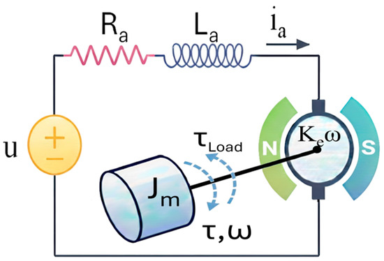
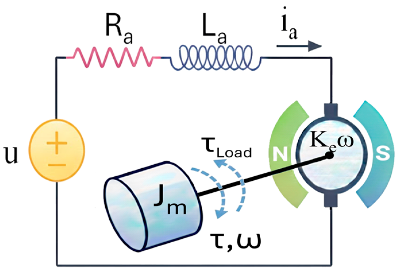
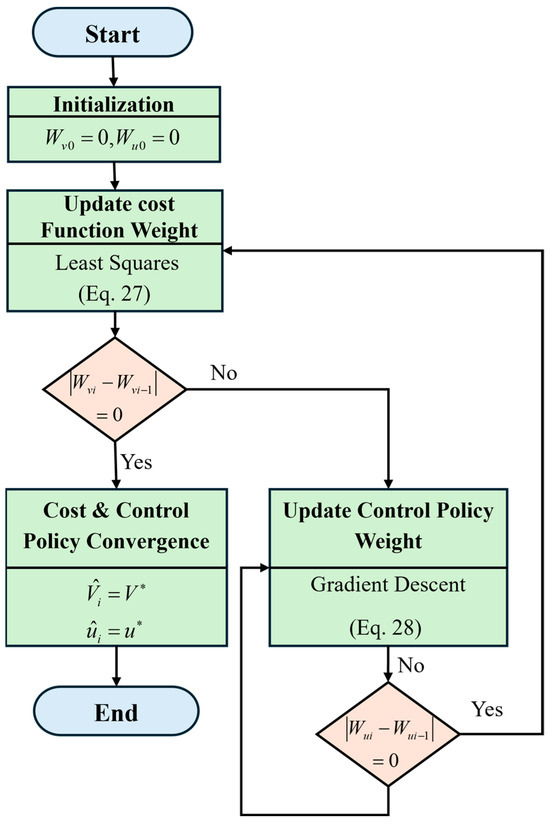
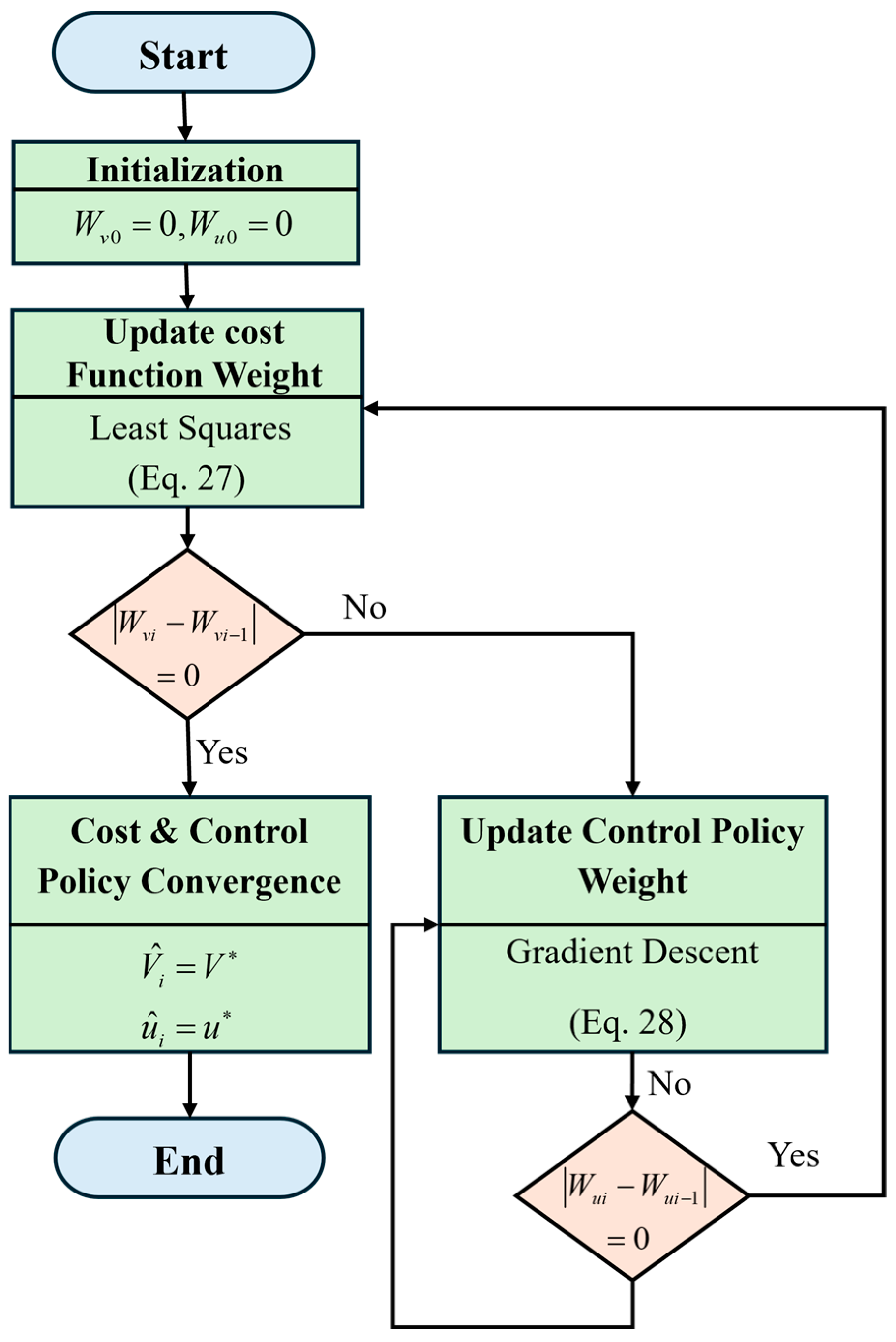
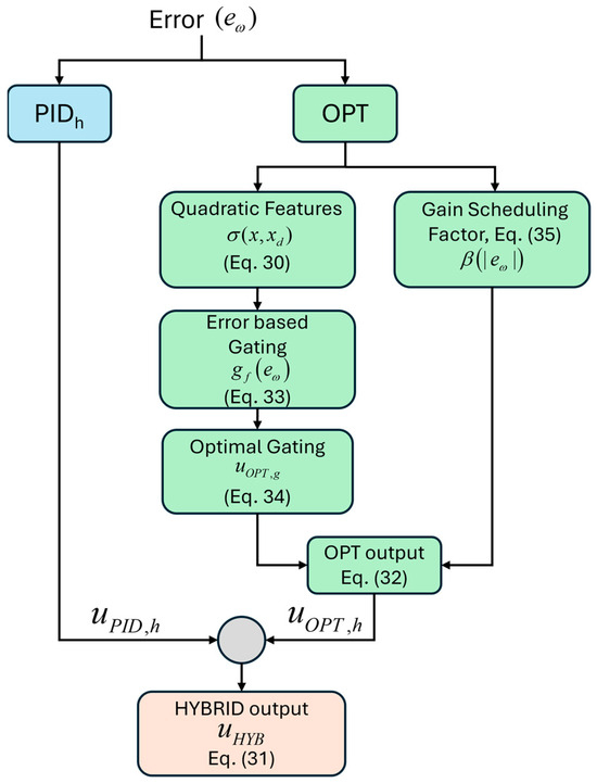
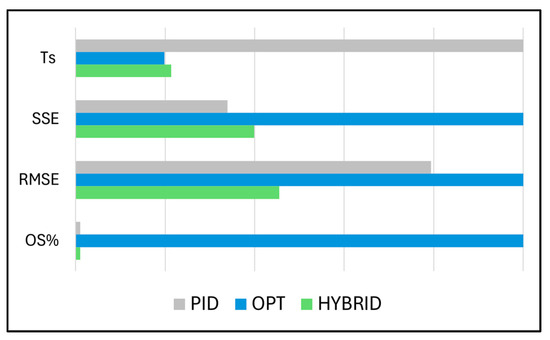
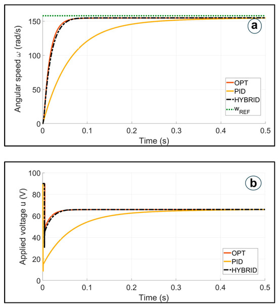
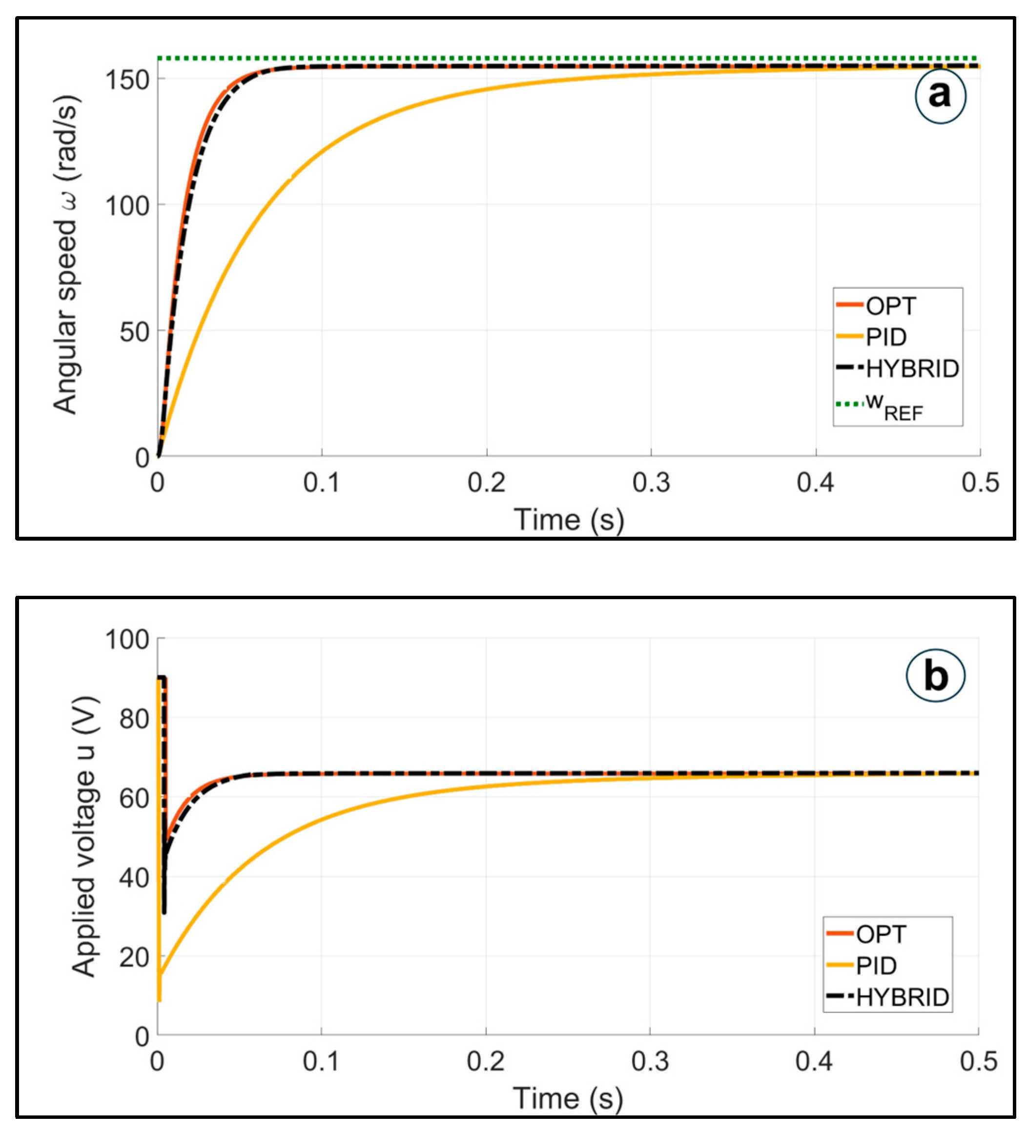
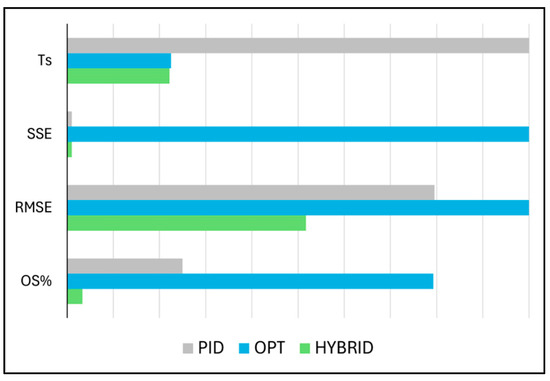
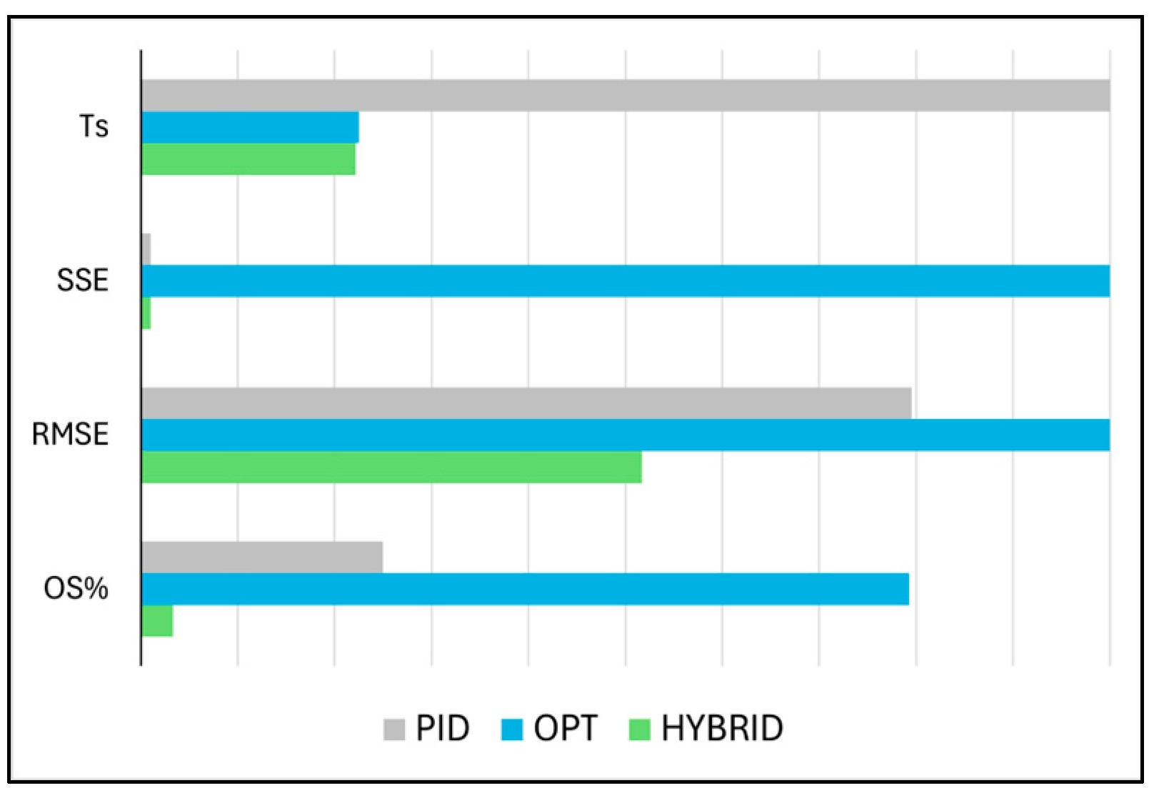

Disclaimer/Publisher’s Note: The statements, opinions and data contained in all publications are solely those of the individual author(s) and contributor(s) and not of MDPI and/or the editor(s). MDPI and/or the editor(s) disclaim responsibility for any injury to people or property resulting from any ideas, methods, instructions or products referred to in the content. |
© 2026 by the authors. Licensee MDPI, Basel, Switzerland. This article is an open access article distributed under the terms and conditions of the Creative Commons Attribution (CC BY) license.