Article

A Quasi-3D Parameterized Equivalent Magnetic Network for the Electromagnetic Analysis of Hybrid-Flux High-Speed Switched Reluctance Motors with High Torque Density

The Electrical Engineering Department, Shenyang University of Technology, Shenyang 110870, China
*
Author to whom correspondence should be addressed.
Actuators 2026, 15(3), 174; https://doi.org/10.3390/act15030174
Submission received: 29 January 2026 / Revised: 2 March 2026 / Accepted: 11 March 2026 / Published: 20 March 2026
(This article belongs to the Section High Torque/Power Density Actuators)

Abstract

To reduce the computational burden of 3D finite element analysis for hybrid-flux high-speed switched reluctance motors (HFHSRMs), a quasi-3D parameterized equivalent magnetic network (EMN) is proposed. A parameterized radial–circumferential cross-grid is used to discretize the stator, air-gap, and rotor regions, and axial coupling branches are introduced to represent key 3D flux paths. Rotor rotation and rotor dislocation are implemented through a circumferential node-shift mapping, thereby avoiding topology reconstruction at different rotor positions. Core nonlinearity is incorporated using a piecewise fit of measured BH data, and sparse-matrix assembly is adopted to improve solution efficiency. Based on the proposed EMN, key electromagnetic quantities are evaluated, including air-gap flux density, static characteristics, and dynamic characteristics. The results are validated against 3D finite element method (FEM) and prototype experiments. In the prototype experiments, the EMN prediction errors of key quantities are within 6%. In addition, computational efficiency is significantly improved compared with the 3D FEM, enabling rapid parameter iteration and early-stage design evaluation for HFHSRMs.

1. Introduction

Switched reluctance motors (SRMs) are attractive candidates for compact high-speed actuation because they offer a simple and robust structure and retain high-temperature capability [1]. However, low torque density and pronounced torque ripple are still commonly encountered in conventional SRMs. This not only limits further enhancement of torque density but also aggravates acoustic noise and vibration. To improve torque density and mitigate torque ripple, various SRM topologies have been proposed, including segmented stator/rotor structures, double-stator configurations, and hybrid excitation/hybrid flux schemes [2,3,4,5,6]. In particular, permanent magnet-assisted hybrid-flux high-speed SRMs (HFHSRMs) can further increase torque density by enhancing flux linkage. Moreover, torque smoothness can be improved by applying rotor dislocation [7]. In HFHSRMs, a mixed flux pattern is formed, i.e., radial excitation and axial flux coupling coexist. Consequently, local saturation and leakage flux become more prominent, and accurate yet efficient electromagnetic performance prediction is required.
Electromagnetic analysis methods mainly include analytical methods [8,9], equivalent magnetic network (EMN) methods [10,11], and the finite element method (FEM) [12,13]. In particular, permeance-based air-gap models and subdomain-based analytical field solutions have been widely used to evaluate the air-gap field distribution with low computational cost [14,15]. However, saturation, complex leakage flux, and axial coupling in hybrid flux structures are difficult to capture accurately within a unified analytical formulation. The FEM provides high accuracy, whereas 3D modeling and computation are usually costly, thereby impeding rapid iteration in early-stage design. To alleviate the computational burden of the FEM, an adaptive FEM has been applied to electrical machine design and analysis [16]. In addition, hp-adaptive FEMs and open-source implementations are also available, such as Agros2D [17]. An EMN offers a compromise between accuracy and efficiency, and material nonlinearity can be incorporated relatively easily. Lumped-parameter EMN (LPEMN) models have been extensively studied, and their accuracy has been improved by refined air-gap permeance and leakage flux modeling [18,19,20]. Nevertheless, magnetic network partitioning remains relatively coarse, and local field variations are still not adequately represented.
To further improve accuracy, mesh-based EMN (MEMN) models have been developed by introducing FEM-inspired meshing concepts [21,22,23,24]. With refined cell partitions, higher fidelity can be achieved at a much smaller computational cost than the FEM, and cross-shaped cells are often adopted for rotating machines to avoid geometric distortion during circumferential discretization. Building on 2D MEMNs, quasi-3D and 3D EMN models have been developed to account for 3D magnetic field effects [25,26]. In EMN-based modeling, relative motion is commonly represented by topology-invariant connectivity updates. In contrast, this paper develops a parameterized cross-grid for HFHSRMs with a prescribed rotor dislocation and integer consistency constraints, and it implements rotor rotation and rotor dislocation in a unified node mapping manner while keeping the mesh partition and numbering unchanged, thereby decoupling rotor rotation from rotor dislocation for efficient multi-position evaluation.
To address the above issues, a parameterized quasi-3D EMN modeling and analysis approach is proposed for HFHSRMs. The following contributions are made:
(1)
A parameterized radial–circumferential cross-grid is formulated, and axial coupling branches are introduced to represent axial flux paths between the stator and rotor magnetic bridges. Key 3D effects are captured while the network size is controlled.
(2)
Rotor rotation and rotor dislocation are realized through a topology-invariant circumferential node mapping scheme, thereby avoiding repeated topology reconstruction across rotor positions.
(3)
Core nonlinearity is incorporated using a piecewise fit to measured BH data, and sparse-matrix assembly, together with iterative acceleration strategies, is applied to improve robustness and efficiency.
On this basis, both static and dynamic electromagnetic characteristics are predicted within a unified framework and are validated by comparisons with 3D FEM and prototype experiments. For clarity, unless otherwise specified, “EMN” refers to the proposed parameterized quasi-3D EMN in this paper.
The remainder of this paper is organized as follows: Section 2 introduces the motor topology and operating principle, Section 3 presents the EMN construction and the nonlinear solution procedure, Section 4 evaluates key electromagnetic characteristics and validates the proposed method through comparisons, and Section 5 concludes the paper.

2. The Topology and Operating Principles of the HFHSRM

2.1. The Topology of the HFHSRM

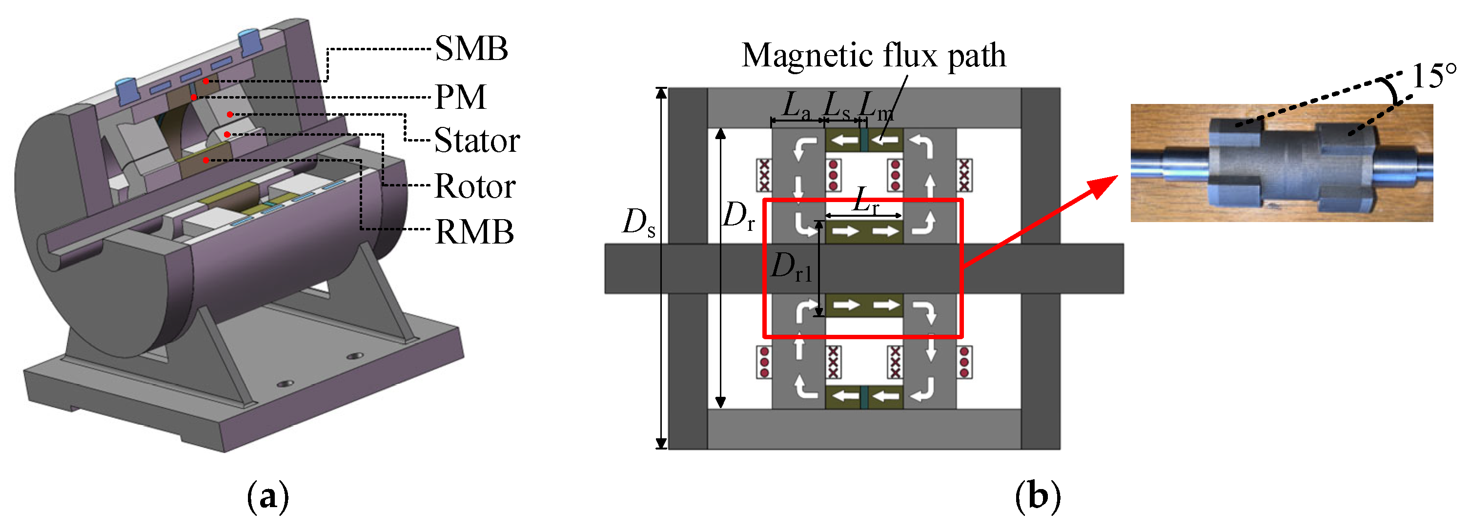
The HFHSRM investigated in this paper is composed of two 6/4 SRM units stacked axially, as shown in Figure 1a. An annular, axially magnetized permanent magnet (PM) is embedded between the stator magnetic bridges on both sides. The axial flux produced by the permanent magnet is coupled into the iron core through the stator magnetic bridge (SMB) and rotor magnetic bridge (RMB), while the windings generate the conventional radial excitation flux. Therefore, a hybrid flux topology is formed, in which radial excitation and axial flux coupling coexist, as illustrated in Figure 1b. The main electromagnetic and structural parameters are listed in Table 1.
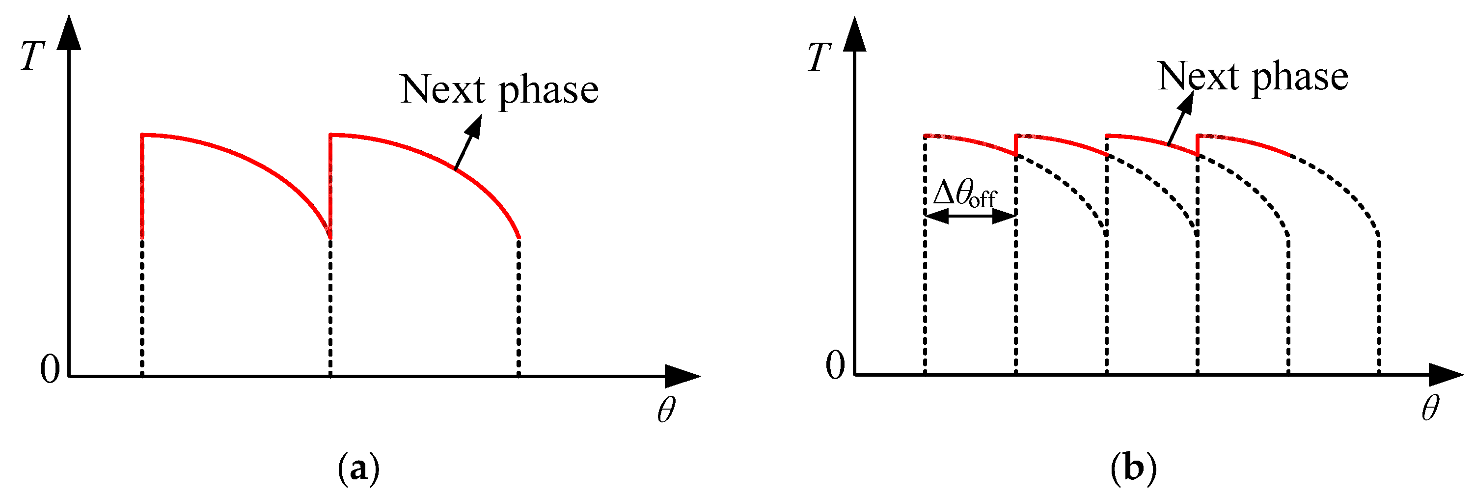
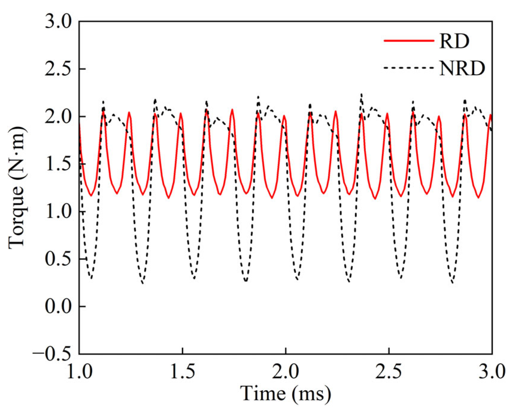
To reduce torque ripple, a rotor dislocation angle is introduced between the two rotor stacks, as shown in Figure 1b. In this paper, the dislocation angle is set to Δθoff = 15° (mechanical angle). The conduction period of a 6/4 SRM unit is θr = 90°. Under the no-rotor-dislocation (NRD) condition, the two rotor stacks are mechanically aligned, so their inductance/torque characteristics are in phase in the mechanical angle domain, thereby resulting in a larger resultant torque ripple after superposition. Under the rotor dislocation (RD) condition, a phase shift in Δθoff is introduced between the inductance/torque characteristics of the two stacks; complementary superposition is then formed in the transition region, and the smoothness of the resultant torque is enhanced. The mechanism is illustrated in Figure 2, and the corresponding torque comparison is shown in Figure 3.

2.2. The Operating Principle of the HFHSRM

The energy conversion mechanism of the HFHSRM is governed by the minimum reluctance principle and is consistent with that of a conventional SRM. When a phase winding is energized, the main flux is established from the excited stator tooth, crosses the air gap into the rotor pole, and returns through the rotor and stator yokes to form a closed magnetic circuit. Electromagnetic torque is produced because the rotor tends to move toward the position of lower reluctance, i.e., toward the aligned position.
Unlike a conventional SRM, an axially magnetized PM is inserted between the stator magnetic bridges on both sides in the HFHSRM. The axial magnetomotive force provided by the PM is coupled to and superposed on the excitation magnetomotive force produced by the winding through the SMB/RMB paths. As a result, the phase flux linkage level is increased and the variation range of the equivalent inductance is enlarged, which enhances torque capability and contributes to torque ripple reduction.

3. EMN Modeling and Nonlinear Solution Procedure

3.1. Modeling Principles

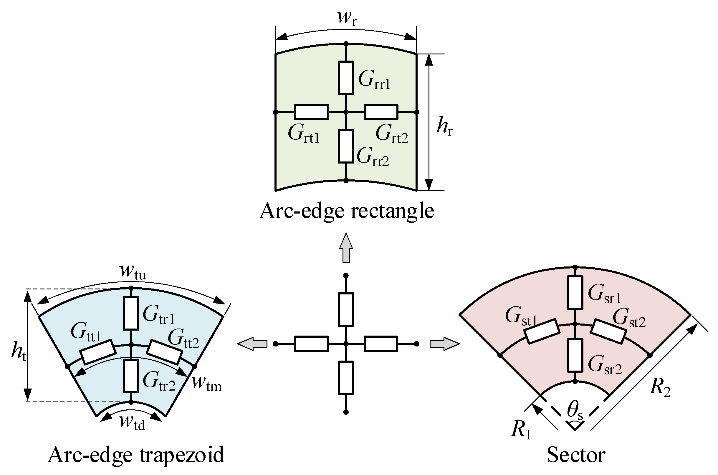
The proposed EMN adopts cross-shaped mesh cells, as shown in Figure 4. Each cell consists of five nodes and four branches. The two radial branches are modeled by the equivalent permeance, Gr, and the two circumferential (tangential) branches are modeled by the equivalent permeance, Gt. According to the geometric features of different regions, three types of cross-shaped mesh cells are employed: arc-edged rectangular cells, arc-edged trapezoidal cells, and sector cells [27]. Their branch permeances are calculated using (1)–(3), respectively.
G rr 1 = G rr 2 = 2 μ 0 μ rr L a w r h r G rt 1 = G rt 2 = 2 μ 0 μ rt L a h r w r
G tr 1 = 2 μ 0 μ tr L a w t u w t m h t ln w t u / w t m ,   G tr 2 = 2 μ 0 μ tr L a w t m w t d h t ln w t m / w t d G tt 1 = G tt 2 = 2 μ 0 μ tt L a h t ln w t u / w t d w t u w t d
G sr 1 = μ 0 μ sr L a θ s ln R 2 / R a v ,   G sr 2 = μ 0 μ sr L a θ s ln R a v / R 1 G st 1 = G st 2 = 2 μ 0 μ st L a ln R 2 / R 1 θ s R a v = R 1 + R 2 2
where μ0 is the permeability of vacuum, La is the axial stack length, and μrr, μrt, μtr, μtt, μsr, and μst are the relative permeabilities of the core material in the corresponding regions.
On this basis, EMN modeling in this paper follows these principles:
(1)
Magnetic flux is assumed to be aligned with the branch direction. Radial flux is carried by radial branches, and circumferential flux is carried by circumferential branches.
(2)
The magnetic field within each mesh cell is assumed to be uniform. The flux density, field intensity, and permeability are assumed constant within a cell.
(3)
The stator and rotor cores are discretized into multiple cells in the radial–circumferential directions. Adjacent cells share nodes, so flux continuity is ensured.
(4)
Each single-side 2D EMN is assumed to be axially uniform by default. Key 3D axial effects are introduced at coupling locations via equivalent axial branches, and an axial flux attenuation factor is applied to account for reduced effective axial coupling.
Note that the above “flux alignment” and “uniform cell” assumptions are inherent to cross-cell MEMN formulations. When strong fringing, oblique flux paths or localized saturation occurs (e.g., tooth tips, slot openings, and magnetic bridges), modeling errors may increase. In this work, such errors are mitigated through mesh refinement in tooth-tip/slot-opening regions (Section 3.2) and by explicitly introducing axial coupling branches at key locations (Section 3.6).

3.2. EMN Topology and Mesh Parameters

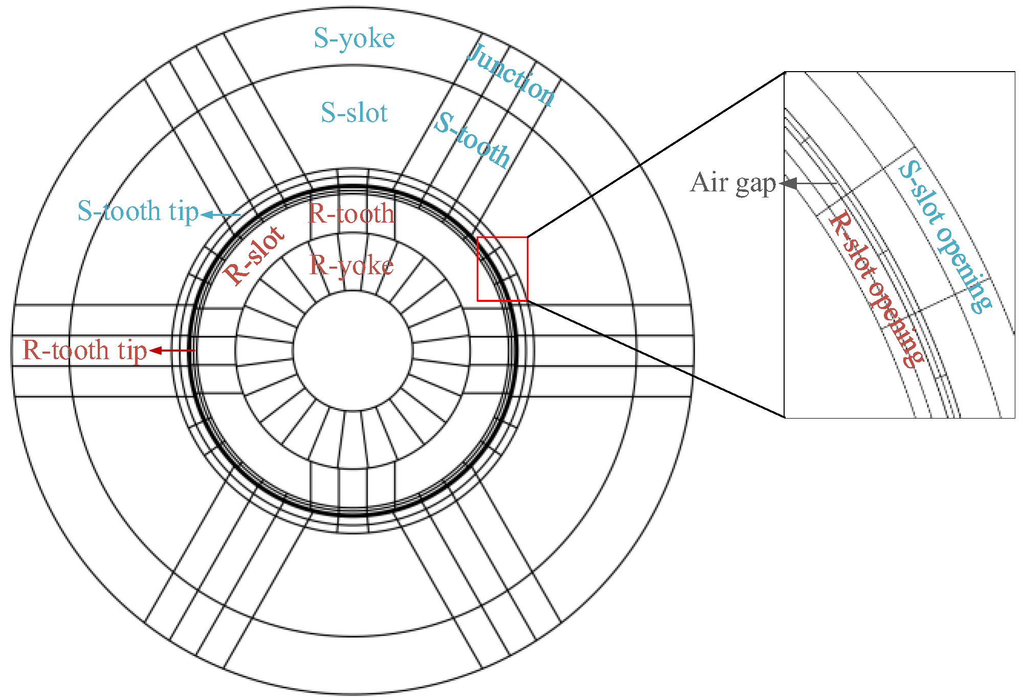
To provide a unified description of the interconnections among the stator, air-gap, and rotor EMNs, an overall EMN partition is first illustrated in Figure 5. In the following subsections, each region is schematically presented using a locally unwrapped view along the circumferential direction, so that the topology and connectivity are shown more clearly. Note that these unwrapped diagrams are used only to illustrate the interconnections; EMN parameter calculation is still based on the actual geometric dimensions and the permeance formulas of the corresponding cells.
In the overall topology, the circumferential discretization of the air gap is characterized by Nag, which is the number of circumferential air-gap cells. The corresponding circumferential angular step is given by (4).
Δ θ a g = 360 ° N a g
To improve circumferential resolution in the tooth-tip/slot-opening layer, the circumferential subdivision parameter, Nsr, is introduced. Consistent node mapping and connectivity between the local mesh and the air-gap mesh are required, as given by (5):
q s = N a g N s r , q s Z
where qs is the number of air-gap cells corresponding to one tooth-tip/slot-opening cell.
The rotor yoke is also discretized uniformly. The circumferential division number is Kry, and the corresponding angular step is given by (6):
Δ θ r y = 360 ° K r y
where Kry is fixed at 24, i.e., each yoke cell corresponds to 15°, which facilitates the implementation of rotor dislocation.
As the circumferential discretization numbers of the rotor tooth region and the rotor yoke region may differ, a consistent coupling rule is required at the tooth–yoke interface. The tooth–yoke circumferential matching factor, qty, is defined by (7). When qty > 1, consistent end-node connectivity is achieved via many-to-one end-node merging.
q t y = N s r / 4 / 3 K r y / 4 / 2 = 2 N s r 3 K r y , q t y Z
From (7), Nsr is required to be an integer multiple of 36. Furthermore, by considering (5) and the requirement that 15° rotor dislocation is implemented in the air gap via cyclic node shifting, Nag is required to be an integer multiple of 72, so that 15° corresponds to an integer number of air-gap angular steps, Δθag.
In addition to the circumferential discretization, radial layering is applied to the stator and rotor tooth-tip/slot-opening regions to capture the more pronounced saturation and local flux variation; other regions use a single radial layer.
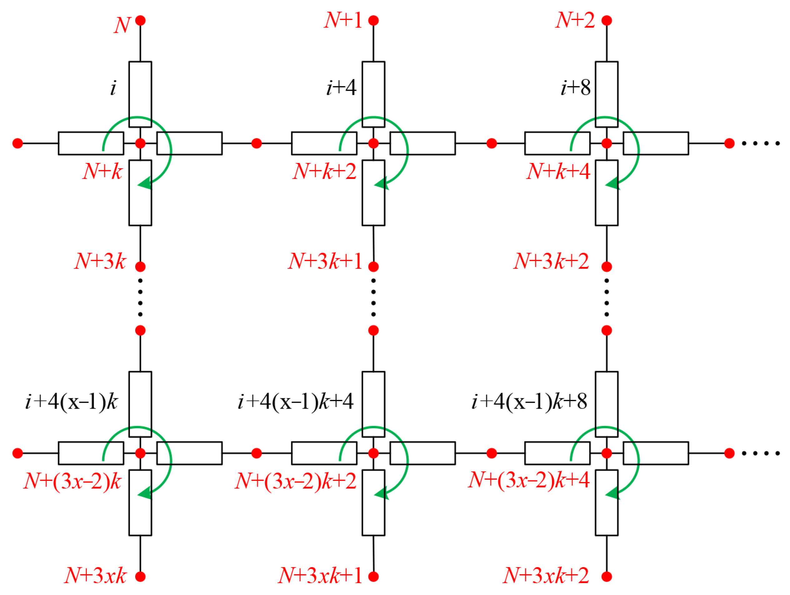
After the above topology and mesh parameters are determined, unified and consistent numbering rules are applied to nodes and branches to facilitate matrix assembly and solution. The nodes are numbered globally in a continuous manner. They are numbered from left to right, and after one row is completed, numbering continues row by row downward until the stator, air-gap, and rotor regions are fully covered. The branches are numbered locally in a continuous manner. Within each cross-shaped mesh cell, the radial and circumferential permeance branches are numbered consecutively in the clockwise direction and are labeled as R1, T1, R2, and T2; for adjacent cells, the branch indices are obtained by adding an offset of 4 in global indexing. With this numbering scheme, each mesh cell corresponds to consecutive indices in the local matrix, which facilitates assembly, debugging, and topology maintenance, as shown in Figure 6.
With this numbering scheme, the node numbering and mesh partition are kept unchanged during the analysis of the relative stator–rotor motion. Topology updating for different rotor positions is achieved by applying a circumferential cyclic shift to the connection indices at the coupling interface, thereby avoiding topology reconstruction. The portability of this topology-updating approach is discussed in Section 3.8.

3.3. Modeling of the Stator EMN

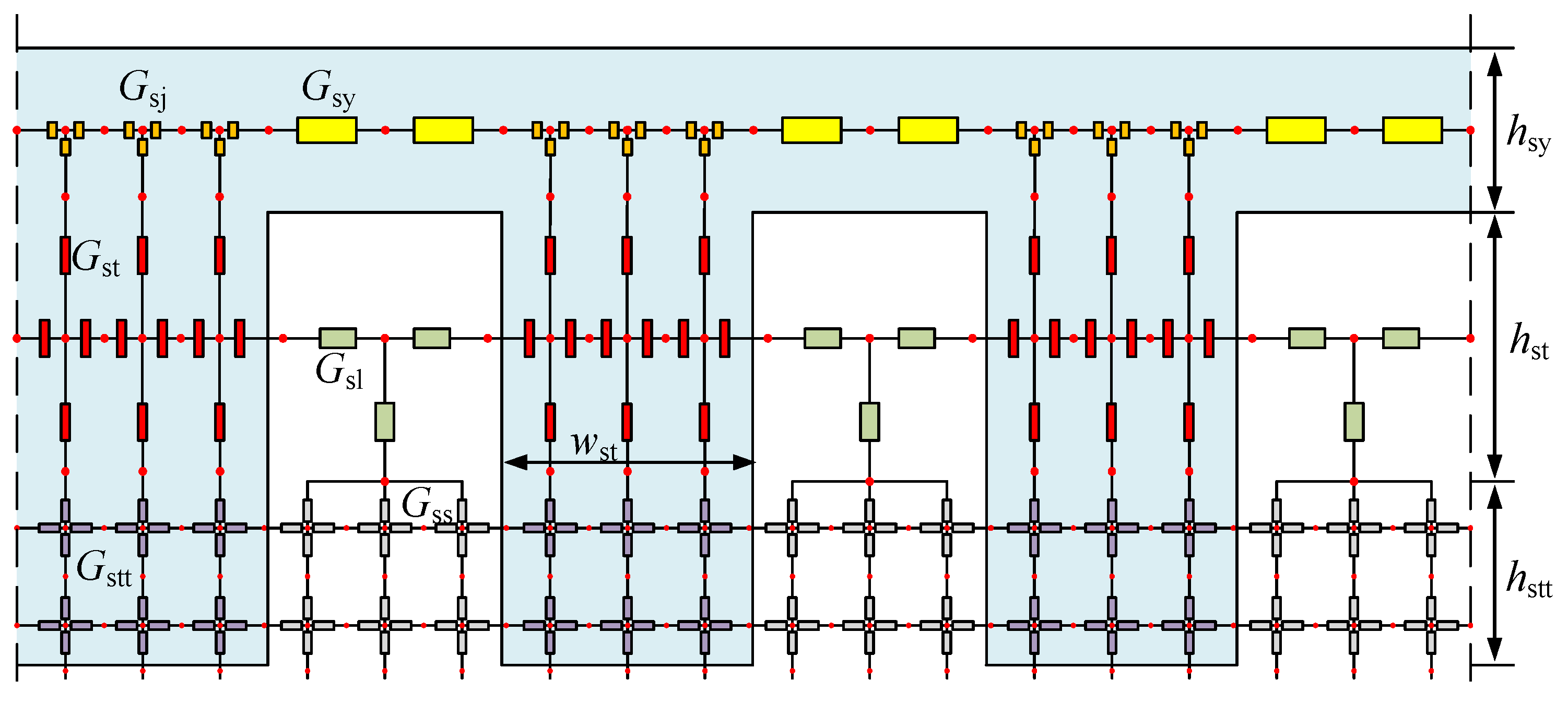
To illustrate the mesh connectivity of the stator EMN more clearly, the stator magnetic circuit is schematically presented using a local linear unwrapping along the circumferential direction, as shown in Figure 7. In the EMN, the stator region is discretized uniformly into cross-shaped mesh cells, and different cell types are selected according to geometric features: arc-edged rectangular cross-cells are used for the stator tooth–yoke junction (Gsj), tooth body (Gst), and tooth tip (Gstt); arc-edged trapezoidal cross-cells are used for the stator yoke (Gsy) and the in-slot region (Gsl); and sector cross-cells are used for the stator slot-opening region (Gss). In the yoke and the tooth–yoke junction, the upper radial branch is used as an equivalent permeance path of the stator magnetic bridge, and the permeance is calculated using its axial length, Ls (see Section 3.6). For mesh cells near boundaries or with missing corners, when only three branches are present, the cell is treated as a degenerated cross-cell: the branch in the missing direction is excluded from the assembly to preserve a unified meshing and numbering rule, which is equivalent to an open condition (zero flux) in that direction.
In the stator EMN, winding excitation is represented by introducing an equivalent magnetomotive force (MMF) source on the radial branch corresponding to the stator tooth body, and its magnitude is determined by the phase current and the effective number of turns, as given by (8):
F s = N e f f i p h
where iph is the phase current, and Neff is the effective number of turns acting on the corresponding stator tooth.

3.4. Modeling of the Rotor EMN

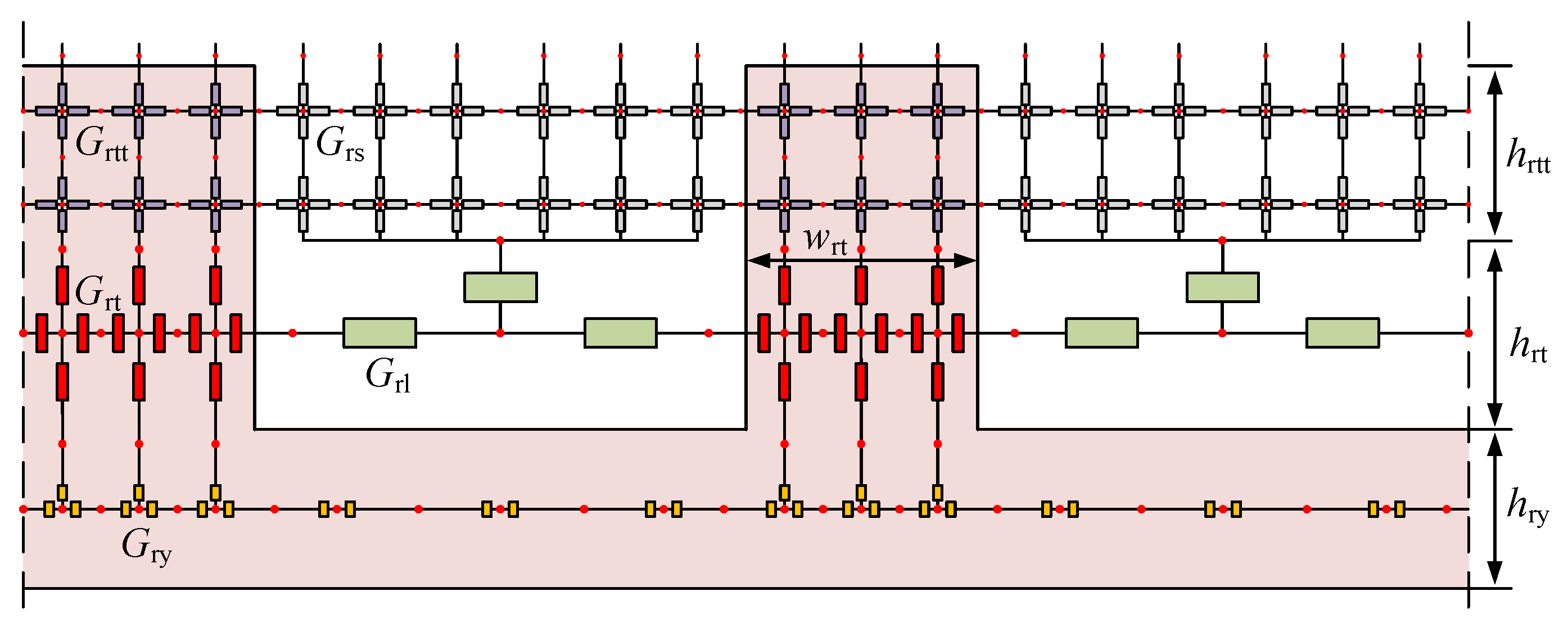
The rotor EMN topology is shown in Figure 8. The cross-shaped mesh discretization is also adopted for the rotor, and the mesh cell types for different geometric regions are as follows: arc-edged rectangular cross-cells are used for the rotor tooth body (Grt) and tooth tip (Grtt); sector cross-cells are used for the slot-opening region (Grs); arc-edged trapezoidal cross-cells are used for the in-slot region (Grl); sector cross-cells are used for the rotor yoke (Gry), which is discretized uniformly along the circumferential direction; and cells with missing corners at the boundary are treated using the same degeneration rule as in the stator EMN, i.e., the branch in the missing direction is excluded from the assembly.
In addition, to represent the axial coupling between the two rotor stacks through the rotor magnetic bridge, axial connection branches are introduced in the rotor yoke. The lower radial branch of a rotor yoke cell on one side is treated as an axial permeance path, and its permeance is calculated using the rotor magnetic bridge length, Lr. An axial connection is then established to the node of the rotor yoke on the other side, thereby coupling the two single-side rotor EMNs through the rotor yoke region.

3.5. Modeling of the Air-Gap EMN

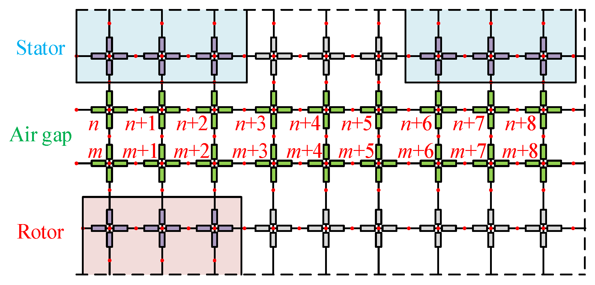
Air-gap EMN modeling is critical for both computational accuracy and the simulation of the relative stator–rotor motion. In this paper, the air gap is discretized into two radial layers of cross-shaped mesh cells [28], as shown in Figure 9. The layer adjacent to the stator is fixedly connected to the last stator mesh layer and remains stationary with the stator, whereas the layer adjacent to the rotor is fixedly connected to the first rotor mesh layer and rotates integrally with the rotor.
During rotor rotation, the partition of the two air-gap mesh layers and the cell permeances are kept unchanged. Only the end-node connectivity between the two layers is updated by a circumferential cyclic shift corresponding to the mechanical rotor angle, so air-gap topology updating at different rotor positions is achieved. In the implementation, the cyclic shift is performed by an integer cell offset of the circumferential index set, consistent with the discretized rotor position grid. The mapping relationship is given by (9):
m = mod n 1 , N a g + 1
where n, m ∈ {1, 2, …, Nag}, and mod(·) is the modulo operator, which keeps the node indices within the range [1, Nag] and thereby realizes a cyclic shift. With this treatment, air-gap coupling is updated without changing the sparsity pattern of the global matrix, thereby avoiding the rebuilding of the global matrix at different rotor positions.

3.6. Quasi-3D EMN Modeling

Based on the above single-side 2D EMN, a quasi-3D EMN model is constructed to represent the axial flux coupling between the two sides and account for the mechanical rotor dislocation between the two rotor stacks. The key idea is to introduce equivalent axial coupling branches in the corresponding regions of the two 2D EMNs. The dislocation relationship is implemented by a circumferential cyclic shift in the node mapping scheme. In this way, radial, circumferential, and axial fluxes are described in a unified manner, while the 2D mesh partition and the numbering system are kept unchanged.

3.6.1. Axial Coupling Branches

Based on the single-side 2D EMN, axial coupling branches are introduced in this paper, as shown in Figure 10. On the stator side, the upper radial branch of the yoke and tooth–yoke junction cells are treated as an axial permeance path of the stator magnetic bridge, and it is connected in series with the PM branch, thereby establishing an axial coupling path between the two stators. On the rotor side, the lower radial branch of the yoke cell is treated as an axial permeance path of the rotor magnetic bridge, and it is directly connected to the corresponding node of the yoke cell on the other side, thereby closing the axial flux between the two rotors and forming a complete axial coupling loop.
The PM branch is represented as an MMF source in series with an equivalent permeance, and its equivalent MMF is given by (10):
F p m = k a x H c L m
where Hc is the coercivity of the PM, and kax is an axial attenuation factor introduced to account for reduced effective axial coupling caused by lamination and assembly. For the prototype studied in this paper, kax is identified once by matching the EMN predictions to reference 3D FEM results, and it is fixed at kax = 0.9 for all operating conditions. Since kax linearly scales the equivalent permanent magnet MMF in (10), if kax deviates slightly around the calibrated value, the axial-coupled component varies approximately proportionally with kax. For different designs (with changes in geometry, lamination, or assembly), kax can be re-identified using a small set of reference data.

3.6.2. Dislocation Implementation

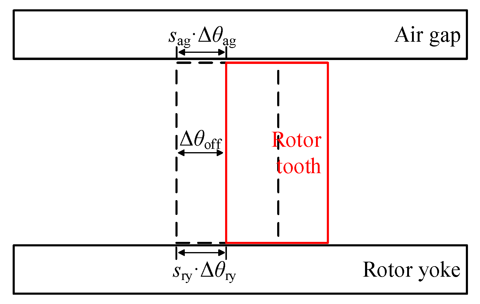
To reduce torque ripple, a fixed mechanical dislocation angle, Δθoff, is introduced between the two rotor stacks. In the EMN, rotor dislocation does not change the internal meshing or the node/branch numbering in each region. Instead, it is implemented by a single update of the node mapping relationship at the coupling interfaces. Specifically, the end nodes at the rotor tooth-tip–air-gap interface and the rotor tooth–rotor yoke interface are circumferentially shifted in a cyclic manner, thereby yielding an equivalent dislocated topology of Side 2 relative to Side 1, as shown in Figure 11.
Let the circumferential discretization step of the air gap be Δθag and that of the rotor yoke be Δθry. The circumferential shift step number corresponding to the dislocation is defined as:
s a g = Δ θ o f f Δ θ a g , s r y = Δ θ o f f Δ θ r y
where sag is used to update the node mapping at the rotor tooth tip–air-gap interface, and sry is used to update the node mapping at the rotor tooth–rotor yoke interface. Both sag and sry are guaranteed to be integers under the discretization constraints in Section 3.2.
In the implementation, the circumferential indices of the corresponding coupling-interface nodes are updated by a cyclic shift according to (12):
k a g = mod k r t 1 + σ a g s a g , N a g + 1 , k r y = mod k r t 1 + σ r y s r y , K r y + 1
where σag and σry ∈ {+1, −1} indicate the shift direction. Note that this dislocation mapping is updated only once when the Side 2 topology is constructed, whereas the air-gap coupling update with rotor position is still handled by the method in Section 3.5. The two updates are independent.

3.7. EMN Nonlinear Iterative Solution and Acceleration Strategies

After the branch permeances and MMF sources are determined, the EMN is solved using the nodal magnetic potential method, and the basic governing equations are given by (13)–(15):
A Y A T F n = A Y F
F d = A T F n
Φ = Y F d F
where A is the incidence matrix, Y is the diagonal permeance matrix constructed from the permeance vector, G, and F is the branch MMF vector; Fn is the nodal magnetic potential vector, Fd is the branch magnetic potential drop vector, and Φ is the branch flux vector.
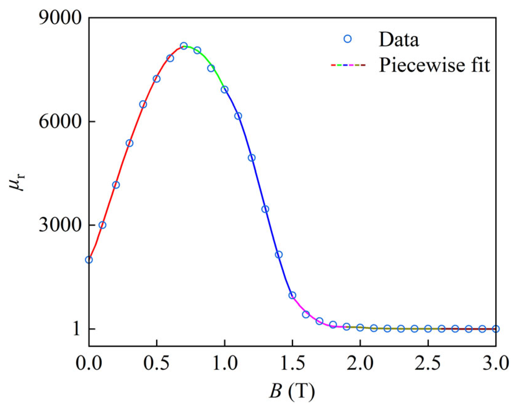
In the HFHSRM, the relative permeabilities of the air gap and the PM are treated as constants, whereas the relative permeabilities of the stator and rotor core regions vary significantly with the flux density, B, and local over-saturation may occur. To model this nonlinearity in the EMN, the relationship, μr(B), is constructed from the measured BH data, and a piecewise fit is adopted to balance fitting accuracy and iterative stability. The unified form of the piecewise fit is given by (16), and the fitted curve is compared with the measured data in Figure 12. The piecewise form enables explicit evaluation of μr(B) during the nonlinear iteration, which is beneficial to computational efficiency and convergence stability.
μ r = 1.20 × 1 0 4 B 3 + 5.09 × 10 3 B 2 + 1.13 × 10 4 B + 1.86 × 10 3 ,       0 T B < 0.7 T                                     1.44 × 10 4 B 2 + 2.04 × 10 4 B + 9.56 × 10 2 , 0.7 T B < 1.0 T 4.32 × 10 4 B 3 1.67 × 10 5 B 2 + 2.00 × 10 5 B 6.93 × 10 4 , 1.0 T B < 1.5 T                                     7.66 × 10 3 B 2 2.81 × 10 4 B + 2.59 × 10 4 , 1.5 T B < 1.9 T 1.08 × 10 3 B 3 + 7.63 × 10 3 B 2 1.80 × 10 4 B + 1.41 × 10 4 , 1.9 T B < 2.6 T                                     6.66 × 10   B 2 + 3.79 × 10 2 B 5.36 × 10 2 , 2.6 T B < 3.0 T
After the piecewise fit relationship, μr(B), is obtained, the relative permeability of each core cell is updated during the iteration by a linear relaxation scheme, and the update equation is given by (17):
μ r k + 1 = α μ r k + 1 α μ r k 1
where α is the relaxation factor (0 < α ≤ 1), μ r k and μ r k 1 are the relative permeabilities obtained from (16) at the k-th and (k − 1)-th iterations, respectively, and μ r k + 1 is the updated relative permeability. The iteration is terminated according to the error criterion in (18), where ε = 10−4 is used in this paper. In the implementation, a maximum iteration number is also imposed to avoid excessive runtime in rare cases of nonconvergence.
max μ r k μ r k 1 μ r k 1 < ε
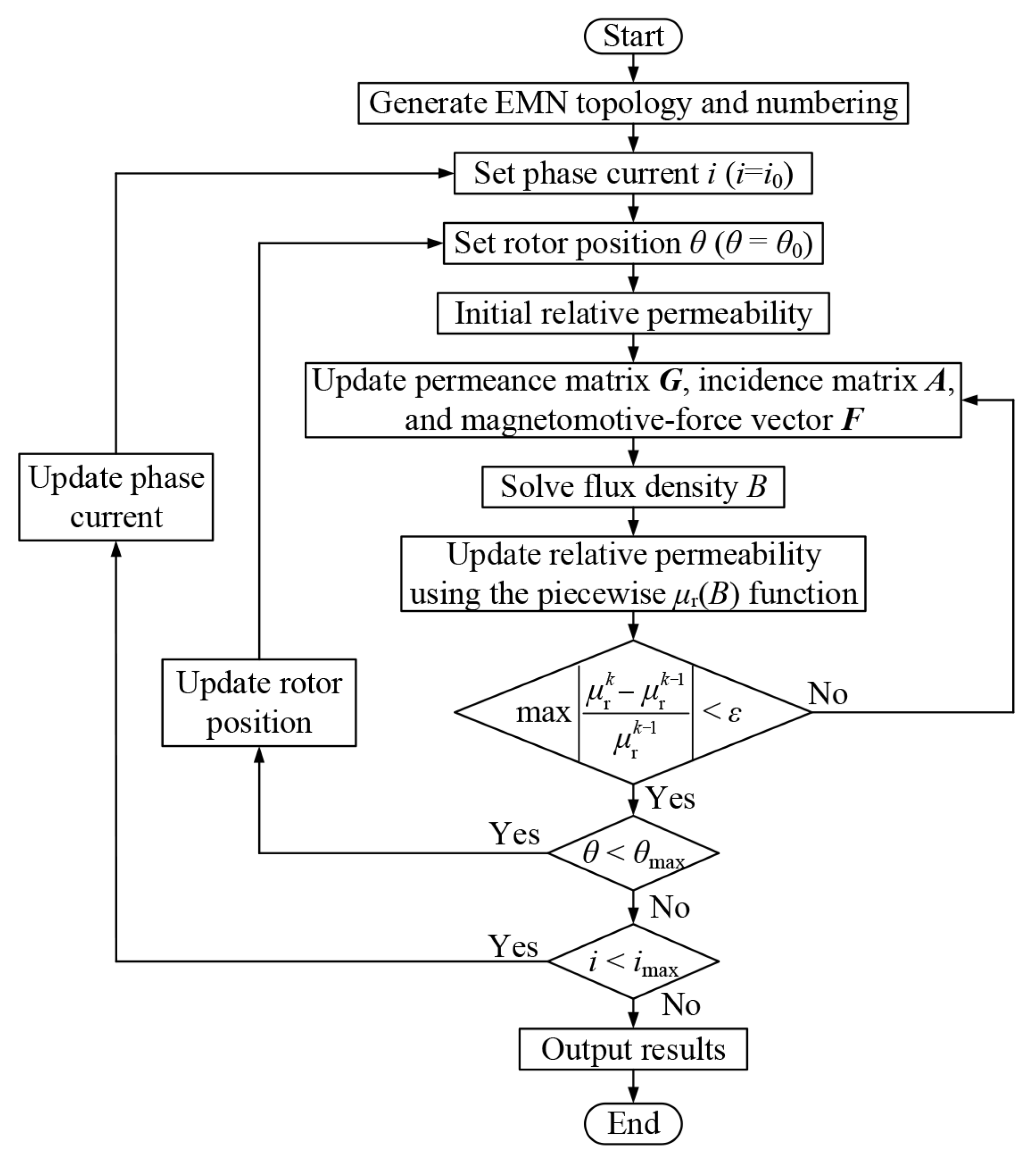
The above procedure corresponds to the iterative solution of the nonlinear EMN at a single operating point defined by a given phase current, I, and rotor position, θ. To obtain the 2D distribution of static characteristics, a 2D scan over i and θ is performed. For each pair (θ, i), the inner nonlinear iteration is completed first until the convergence criterion is satisfied, and then θ and i are stepped sequentially according to the prescribed step sizes over the entire calculation range. The overall workflow is shown in Figure 13.
Following the workflow in Figure 13, Table 2 compares piecewise fitting and direct interpolation for μr(B) update for different Nag values using the same convergence tolerance, ε, maximum iteration number (300), and relaxation factor, α = 0.91. The results indicate that piecewise fitting exhibits faster and more stable convergence than direct interpolation, thereby reducing the overall runtime.
The EMN solution is implemented in MATLAB R2024a. Because the 2D scan significantly increases the number of operating points, computational efficiency becomes critical. Therefore, the following acceleration strategies are applied in the EMN solution:
(1)
During nonlinear iteration, only core branch permeances varying with B are updated, while air-gap and PM branch permeances remain constant.
(2)
The incidence matrix, A, and the diagonal permeance matrix, Y, are constructed in sparse form, and the resulting linear system is solved using sparse matrices, reducing memory usage and improving solution efficiency.
(3)
Vectors and matrices repeatedly updated in the 2D scan are preallocated and reused, so the overhead caused by repeated allocation inside loops is avoided.
(4)
For adjacent rotor positions at the same current, the previous converged μr is reused as the initial value, reducing iterations and accelerating convergence.

3.8. Modeling Portability

In many EMN studies, portability is limited by machine-specific manual partitioning. Here, portability refers to the reusability of the model construction workflow, enabled by layered construction, parameter-driven automatic partition, and interface index mapping. In this paper, the framework is demonstrated and validated on an HFHSRM prototype; extension to other rotating machine topologies can be achieved by updating the layer configuration and discretization parameters and will be investigated in future work.
(1)
Layered modular construction
The EMN is constructed layer by layer along the radial direction, including yoke, tooth/slot, tooth-tip/slot-opening, and air-gap layers, together with the corresponding rotor layers. A local subnetwork is generated within each layer, and the full EMN is assembled by connecting adjacent layers through interface nodes. Therefore, model porting mainly requires updating the layer configuration and layer dimensions rather than rewriting the construction logic.
(2)
Automatic partition via parameterized cross-grid templates
Within each layer, the cross-grid and region partitioning are generated automatically from discretization parameters, such as Nag and a few radial layering numbers for key regions. A fixed library of cell templates is assigned to the generated regions, so the construction rules remain unchanged. Portability is achieved by updating discretization parameters, region dimensions, and region-to-template assignments.
(3)
Topology-invariant interface mapping for motion and offsets
Relative motion is handled by index mapping at the coupling interface rather than topology reconstruction. Rotor rotation is implemented by a circumferential cyclic shift in interface connection indices while keeping node numbering and layer partitioning unchanged. The same mapping mechanism can also represent prescribed circumferential offsets between coupled periodic sections when integer index correspondences (one-to-one or many-to-one) are available. As an additional configuration, the no-dislocation case (Δθoff = 0) was also evaluated by setting the dislocation offset to zero in the same mapping without changing the underlying construction.
Note that machine-specific effects can be introduced as optional modeling modules on top of the common framework. For example, axial coupling branches and PM excitation sources are enabled only when corresponding physical paths exist and are disabled otherwise. Parameters associated with machine-specific effects (e.g., the axial attenuation factor kax) are design-dependent and can be identified once per design using a small set of reference data (3D FEM points or measurements).

4. 3D FEM and Experimental Validation

4.1. 3D FEM Modeling

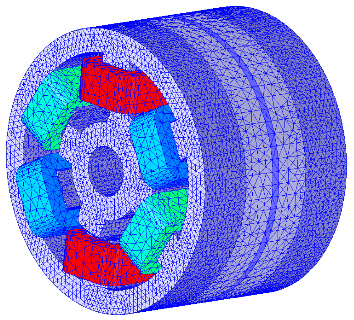
To validate the quasi-3D EMN proposed in Section 3, a 3D FEM model of the HFHSRM is developed, and its results are compared with the EMN predictions. The comparison metrics include air-gap flux-density distribution, static characteristics (phase flux linkage, inductance, and static torque), and instantaneous electromagnetic torque. The 3D FEM model and meshing configuration of the HFHSRM are shown in Figure 14.

4.2. Electromagnetic Performance Verification

4.2.1. Air-Gap Flux Density

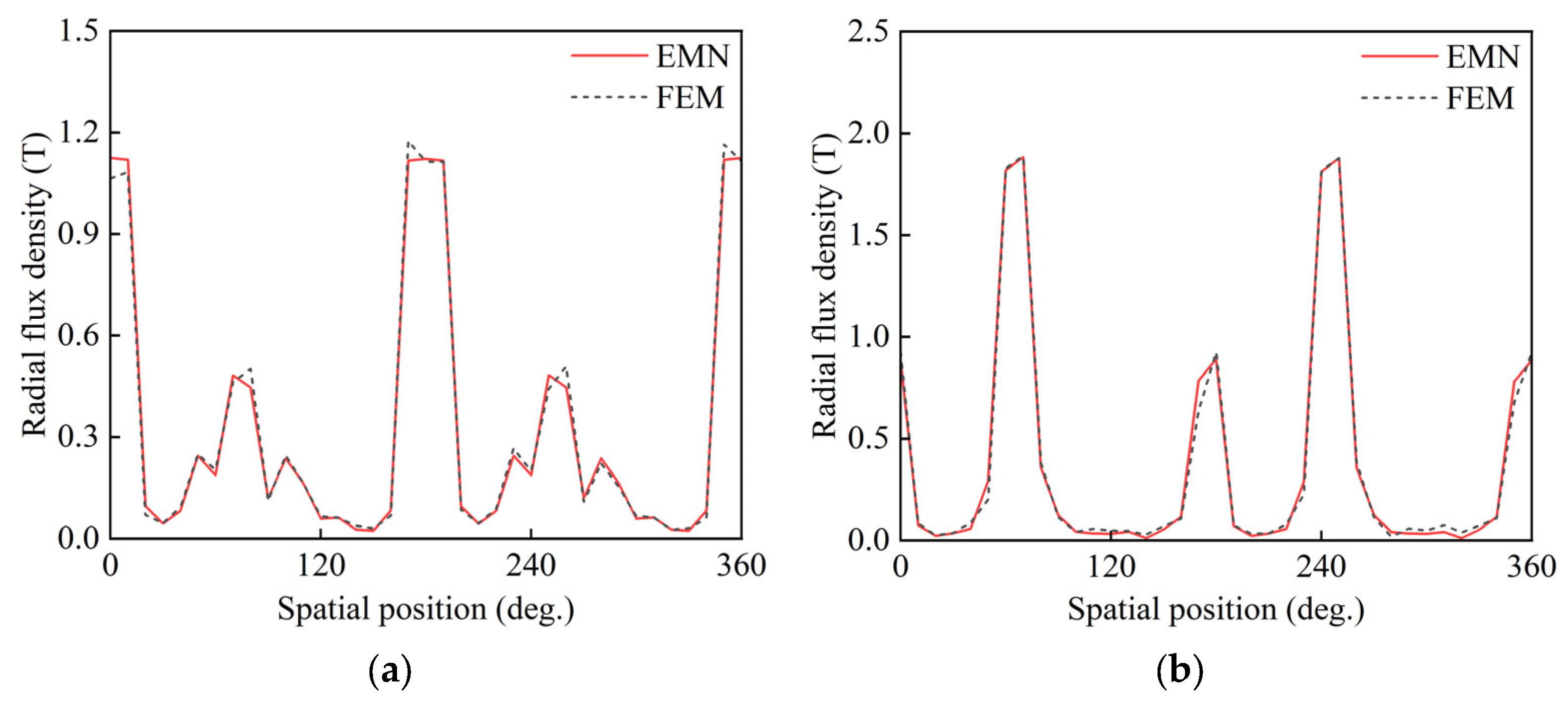
In this section, the air-gap radial flux-density distribution at the aligned stator–rotor position is compared for the EMN and FEM, as shown in Figure 15. The waveforms obtained by the two methods are consistent in terms of the main peak magnitude and location, and the overall trend agrees well. For the left air gap, the EMN reproduces the main peak and the ripples near the slot opening, and the relative error relative to FEM is 4.29%; for the right air gap, the EMN also follows the distribution of peaks and valleys well, and only slight deviations are observed at a few peak tops and local extrema, with a relative error of 5.25%. These results indicate that the proposed air-gap EMN model describes the magnetic field distribution in both air gaps of the HFHSRM with good accuracy under the aligned condition. The relative error, δ, is calculated by (19):
δ = 1 n i = 1 n B F E M i B E M N i B F E M i × 100 %
where BEMN(i) and BFEM(i) are the air-gap radial flux densities at the i-th sampling point predicted by the EMN and FEM, respectively, and n is the number of sampling points.

4.2.2. Static Characteristics

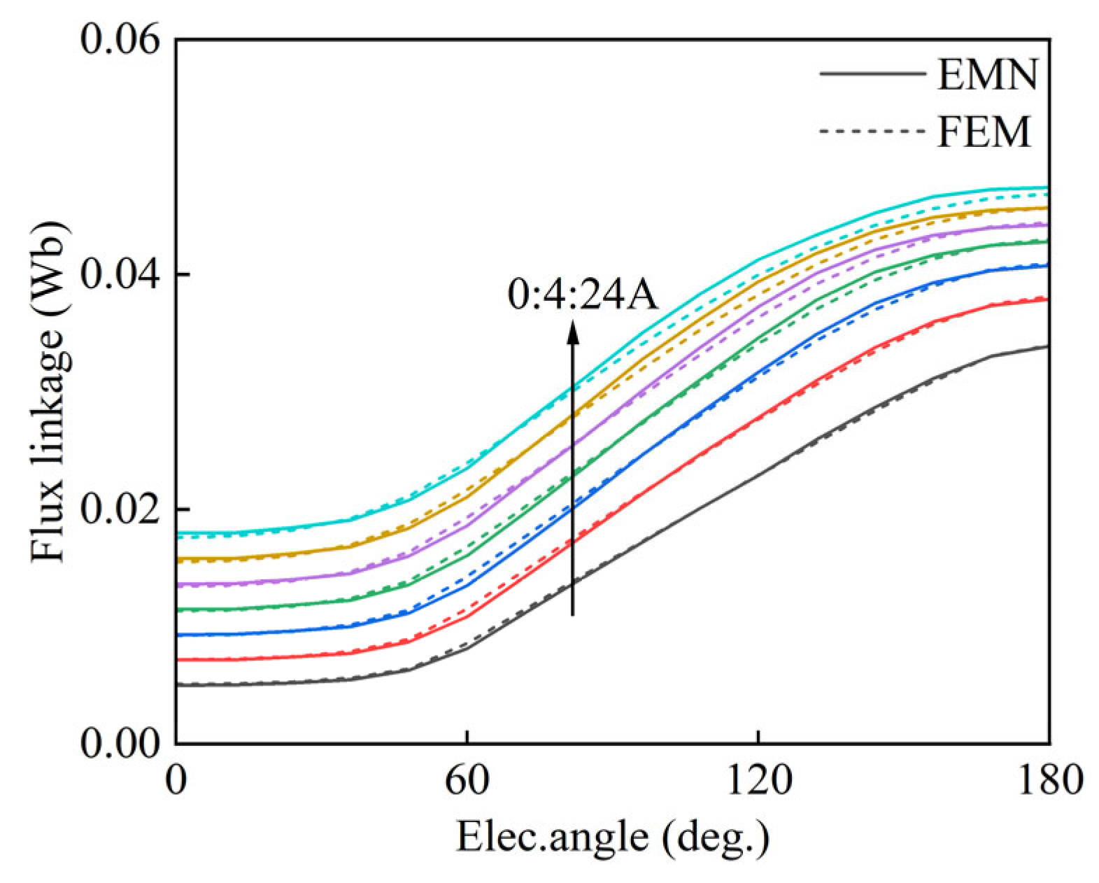
Static characteristics are electromagnetic quantities computed with the rotor fixed and a specified current applied to a single phase. They mainly include the phase flux linkage characteristic, the inductance characteristic, and the static torque characteristic. To cover the range from the linear region to deep saturation, the excitation current is scanned from 0 to 24 A with a step of 4 A. Note that, in the following figures, rotor position is presented in electrical degrees (elec. deg.) for clearer presentation over one electrical cycle.
(1)
Phase flux linkage
The EMN solution yields the branch flux Φb (θ, i). The phase flux linkage is obtained by summing the radial main-flux branches of the phase tooth poles:
ψ x θ , i = N c m = 1 n t b Ω x , m Φ b θ , i
where Nc is the number of turns of a single phase winding, Ωx,m is the set of radial main flux branches corresponding to the m-th tooth pole of that phase, and nt is the number of tooth poles in this phase (nt = 2 in this paper).
The flux linkage curves obtained from (20) are shown in Figure 16. The EMN-predicted flux linkage variation versus rotor position agrees well with the FEM results. The nonlinear increase with current and the saturation trend at high current are also captured. Table 3 summarizes the relative errors of flux linkage at different currents. The mean relative error is 4.13%, indicating good flux linkage prediction accuracy across different currents and rotor positions.
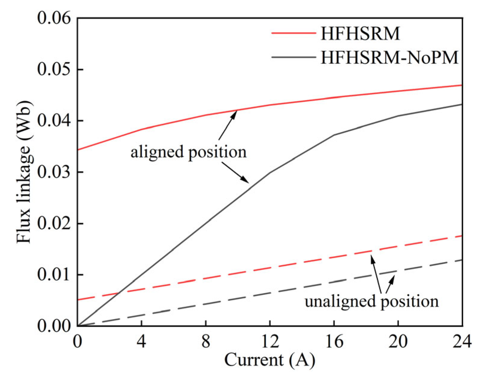
To illustrate the influence of the PM on the magnetization characteristics, the magnetization (ψi) curves are extracted at the aligned and unaligned positions and compared with those of HFHSRM-NoPM, as shown in Figure 17. Because the PM provides a bias MMF, a flux linkage offset is observed for the HFHSRM in the low-current region, and the flux linkage remains higher than that of HFHSRM-NoPM over the entire current range. This comparison indicates that the introduction of the PM increases the flux linkage level and enlarges the area enclosed between the magnetization curve and the current axis (magnetic co-energy), which is beneficial for improving torque density.
(2)
Inductance
Because the magnetic circuit is nonlinear, the inductance varies with θ and i and is expressed as L(θ, i). Two inductance definitions are used in this paper, i.e., the secant inductance and the incremental inductance [29]. The secant inductance describes the average magnetization from zero current to the current operating point, and it is defined by:
L s θ , i = ψ s θ , i ψ s θ , 0 i , i > 0
where ψs(θ, 0) is the biased flux linkage at zero current. For the PM-assisted structure, this term is used to remove the PM-induced flux linkage offset, so the secant inductance mainly reflects the flux linkage component caused by the current increment.
The incremental inductance describes the local magnetization near the operating point and is defined as the derivative of flux linkage with respect to current (tangent slope):
L d θ , i = ψ θ , i i θ
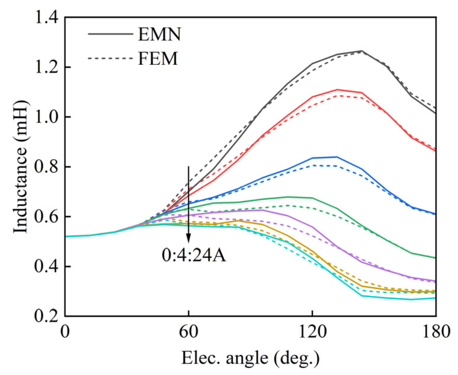
The incremental inductance is obtained from the discrete flux linkage data ψ(θ, i) by numerical differencing and is used to compare inductance results between the EMN and FEM. The inductance curves are shown in Figure 18. The EMN captures the overall variation trend of inductance with rotor position, and good agreement with FEM is achieved. The inductance reduction and the enhanced saturation with increasing current are also reflected. Table 4 lists the relative errors of inductance at different currents. In the low-current range, the error remains within 1.55% to 1.63%; it increases with current and reaches 6.51% at 24 A. The mean relative error over the full current range is 2.96%. These comparisons verify the accuracy of the EMN for static inductance characteristics.
(3)
Torque
The static torque of the HFHSRM is obtained by the virtual work method under constant current as the partial derivative of magnetic co-energy with respect to rotor angle θ:
T e θ , i = W θ , i θ i = const
where the magnetic co-energy W′(θ, i) is defined as:
W θ , i = 0 i ψ θ , i d i
In the EMN solution, the flux linkage, ψ, is obtained at discrete current and angle points. For each angle point, the magnetic co-energy is integrated along the current axis using trapezoidal integration:
W k , j m = 0 k 1 ψ m + 1 , j + ψ m , j 2 i m + 1 i m
When θ is sampled with a uniform step, torque is computed by a second-order central difference approximation:
T e , k , j W k , j + 1 W k , j 1 2 Δ θ
where Δθ is in radians. Note that ψ(θ, i) includes the PM-biased flux linkage in the HFHSRM. Therefore, the torque computed from (23)–(26) represents the total electromagnetic torque under constant current condition.
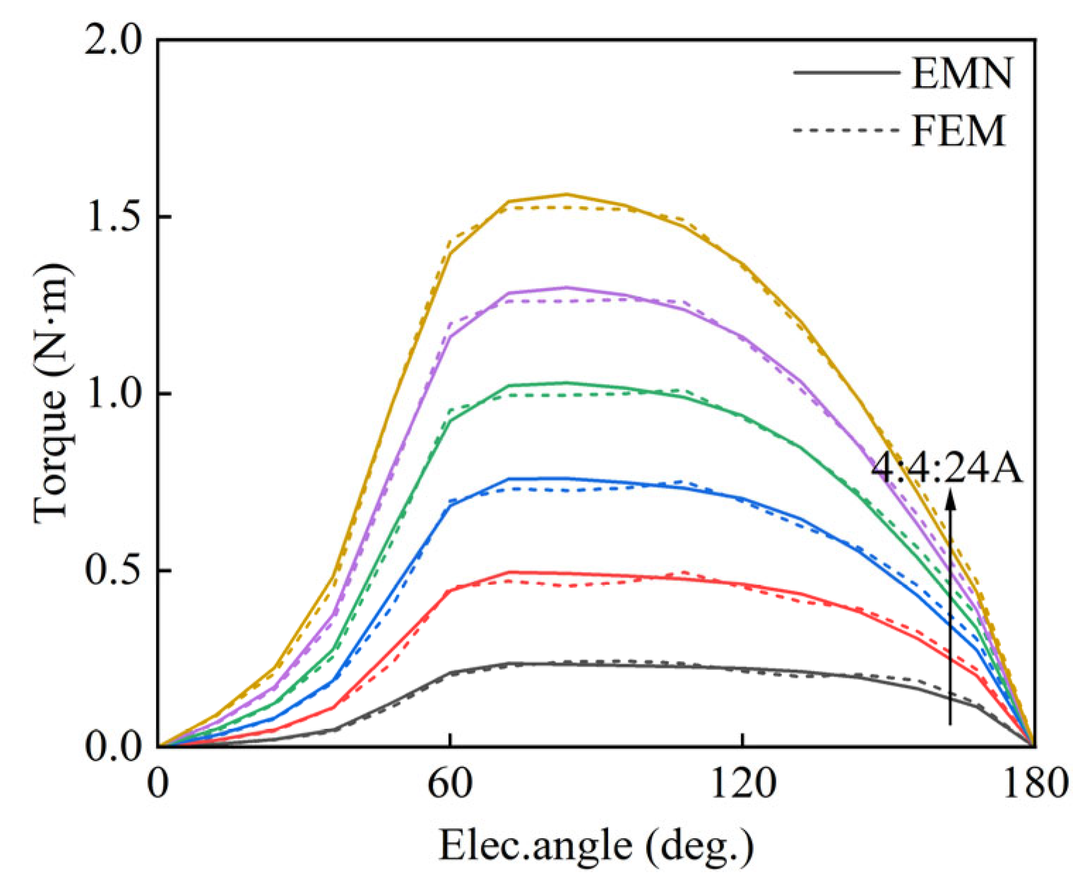
The static torque results are shown in Figure 19. The torque waveforms predicted by the EMN agree well with the FEM results in terms of the overall trend. The torque magnitude increases with current, while the increase becomes less pronounced at high current, indicating that the magnetic circuit gradually enters saturation. Table 5 summarizes the relative errors of static torque at different currents, and the mean relative error is 3.34%.

4.2.3. Dynamic Characteristics

To validate the EMN in predicting dynamic characteristics under operating conditions, the phase current and dynamic torque predicted by FEM and the EMN are compared in this section. In FEM, a time-stepping solution is performed under specified conditions (e.g., rotor speed and DC bus voltage), and the phase currents and dynamic torque are obtained directly. By contrast, in the EMN, a lookup table (LUT) mapping of electromagnetic quantities is built from the static characteristics [30], and the phase-winding voltage equation is established from the flux linkage relation, as given by (27). Note that this dynamic evaluation is based on the quasi-static mappings ψ(θ, i) and T (θ, i) extracted from static characteristics; rate-dependent losses are not included. Accordingly, the dynamic results are interpreted within a magnetoquasi-static LUT framework, while higher-frequency or fast-transient conditions may require frequency-dependent corrections or loss-coupled extensions to account for eddy current and iron loss effects.
d ψ k t d t = u k t R i k t
where uk (t) is the phase-k terminal voltage, and R is the phase resistance (R = 0.14 Ω). Given the static map ψk = ψ(θk, ik), the current is obtained by inverse interpolation, as in (28).
i k t = ψ 1 ψ k t , θ k t
After ik(t) is obtained under operating conditions, the EMN computes the per-phase torque by querying the static torque table T(θ, i) at (θk(t), ik(t)).
T k t = T θ k t , i k t
The total torque is then obtained by summing the phase torques:
T EMN t = k = 1 6 T k t
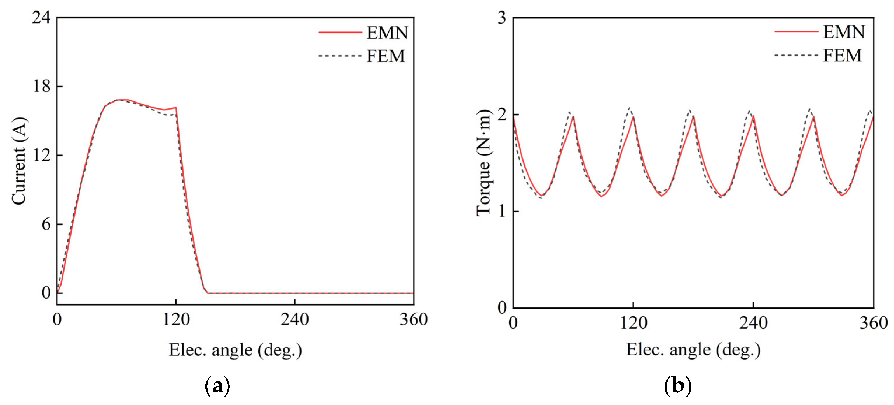
The phase current comparison is shown in Figure 20a. The current waveform predicted by the EMN agrees well with the 3D FEM results in terms of phase and the main transition intervals, and the mean relative error is 4.05%. The dynamic torque comparison is shown in Figure 20b. The torque waveforms match closely in phase and the overall trend, and the mean relative error is 4.06%.
Meanwhile, to characterize the torque level and ripple, the mean torque and the torque ripple coefficient are calculated by (31):
T ave = 1 N n = 1 N T n , δ T = T max T min T ave × 100 %
where T(n) is the torque at the n-th sampling point, N is the number of sampling points, Tmax, Tmin, and Tave are the maximum, minimum, and mean torque, respectively, and δT is the torque ripple coefficient. Torque metrics from both methods are compared in Table 6.

4.3. Evaluation of Computational Accuracy and Efficiency

The prediction accuracy of the EMN has been validated in the previous subsections. To further evaluate its computational efficiency and resource consumption, comparisons are performed in terms of mesh parameters and computational resources.
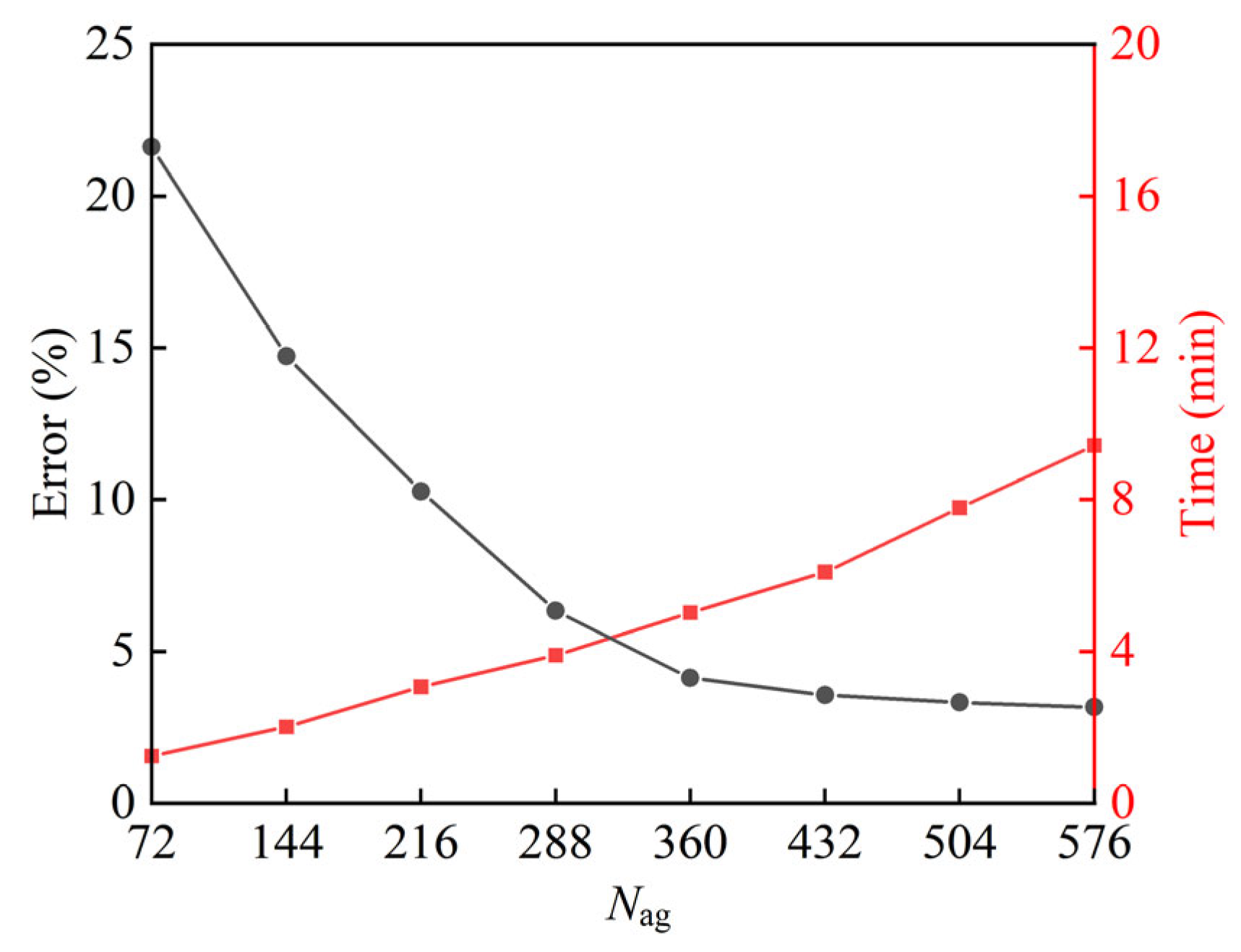
First, the air-gap circumferential discretization number, Nag, affects both accuracy and runtime. With other parameters fixed, the error and computation time under different Nag are evaluated. The error is defined as the mean relative error of the phase flux linkage, calculated as in Table 3. Nsr is selected with Nag by (5) to ensure consistent node mapping. The results are shown in Figure 21. As Nag increases from 72 to 360, the error drops rapidly, whereas further refinement only provides marginal improvement while the runtime continues to increase. By balancing accuracy and efficiency, Nag = 360 is selected as the final mesh configuration, and the EMN results reported above are also based on this setting.
Second, Table 7 compares the EMN and FEM in model scale, computation time, and peak memory usage on the same platform (Intel Core i7 3.4 GHz, 64 GB RAM). As shown in Table 7, the EMN contains 13,776 equivalent network elements, which is only 3.99% of the 344,968 FEM mesh elements; the computation time is 0.1 h (a 95.24% reduction compared with FEM), and the peak memory usage is 2.3 GB (about 10.70% of FEM). Therefore, while accuracy is maintained, the EMN significantly reduces model scale and resource consumption, and it is more suitable for parameter sweeps and design optimization.

4.4. Prototype Experimental Verification

To further validate the prediction capability of the proposed EMN, an HFHSRM experimental platform is built. Static tests are performed for the static torque and static flux linkage characteristics, and the results are compared with the FEM and EMN predictions. Dynamic tests are conducted to measure the phase current waveform and the torque output. The torque is evaluated mainly in terms of mean torque, and the corresponding error statistics relative to experiments are summarized in Table 8.
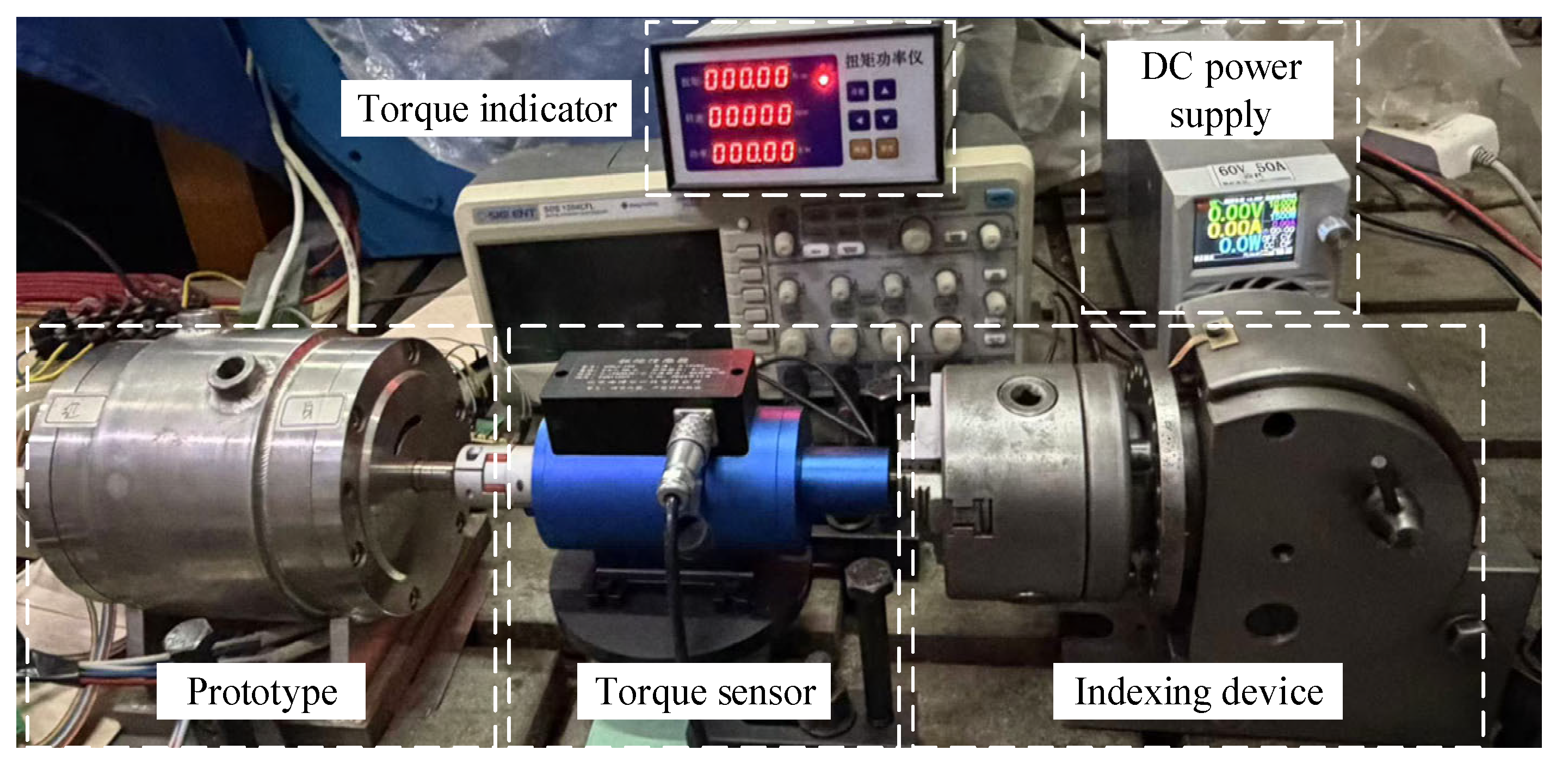
The static experimental setup is shown in Figure 22. The prototype output shaft is connected coaxially to a torque sensor, and rotor mechanical angle positioning and locking are achieved by an indexing device. For consistency between experiments and simulations, the mechanical angle, θ, is referenced to the torque zero-crossing position obtained under single-phase excitation of the phase winding corresponding to the right-side stack; this position is defined as θ = 0°. For both the static torque and static flux linkage tests, the rotor is scanned over one pole pitch (0–90° mechanical) with a 1° mechanical step.
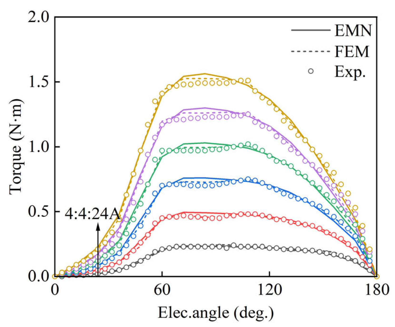
In the static torque test, the excitation current is supplied to a single-phase winding using an adjustable DC power supply. At each rotor angle, the steady-state torque is read three times and averaged to reduce random fluctuations. For each current level, the rotor is first returned to the torque zero-crossing position to re-check the angular reference, and then the torque is recorded from θ = 0° to 90°. This procedure is repeated for all tested current levels up to 24 A to obtain the static torque characteristic T(θ,i). The comparison results are shown in Figure 23.
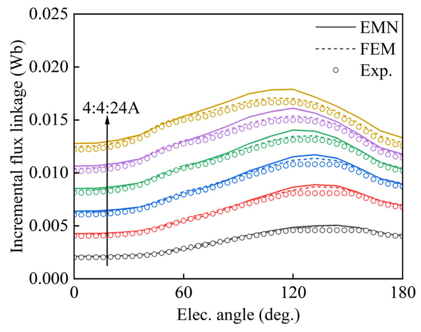
Static flux linkage is obtained through the voltage integration method [31]. With the rotor angle, θ, fixed, the phase current is ramped from 0 to the target value i (i = 4, 8,…, 24 A), while the winding terminal voltage, u(t), and phase current, i(t), are recorded synchronously. The incremental flux linkage referenced to i = 0 is calculated as:
Δ ψ θ , i = ψ θ , i ψ θ , 0 = t 0 t 1 u t R i t   d t
where R is the phase resistance at the test temperature, and [t0, t1] denotes the current-ramp interval. In the experiment, u(t) is measured differentially, and a low-pass filter is applied prior to the integration to reduce measurement noise. Since ψ(θ, 0) is not directly measurable in this test, the experimental result is reported as Δψ(θ, i), and the FEM/EMN results are post-processed as Δψsim(θ, i) = ψsim(θ, i) − ψsim(θ, 0). The comparison results are shown in Figure 24.
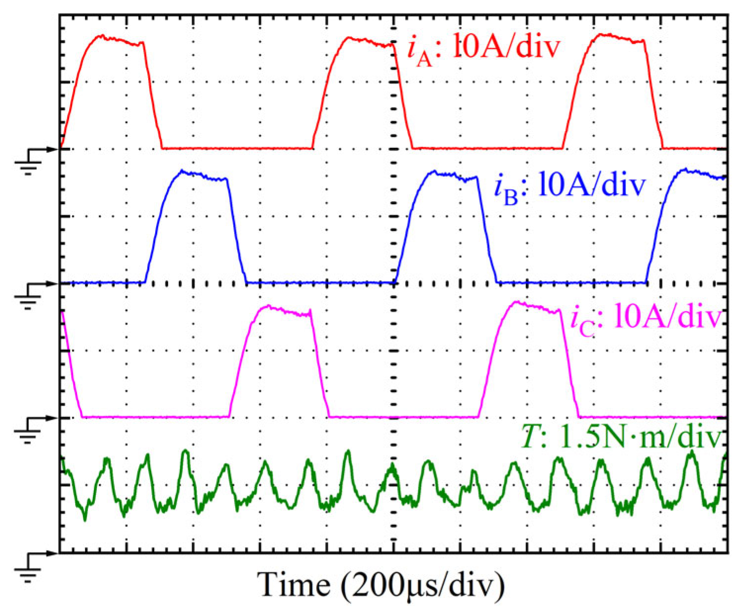
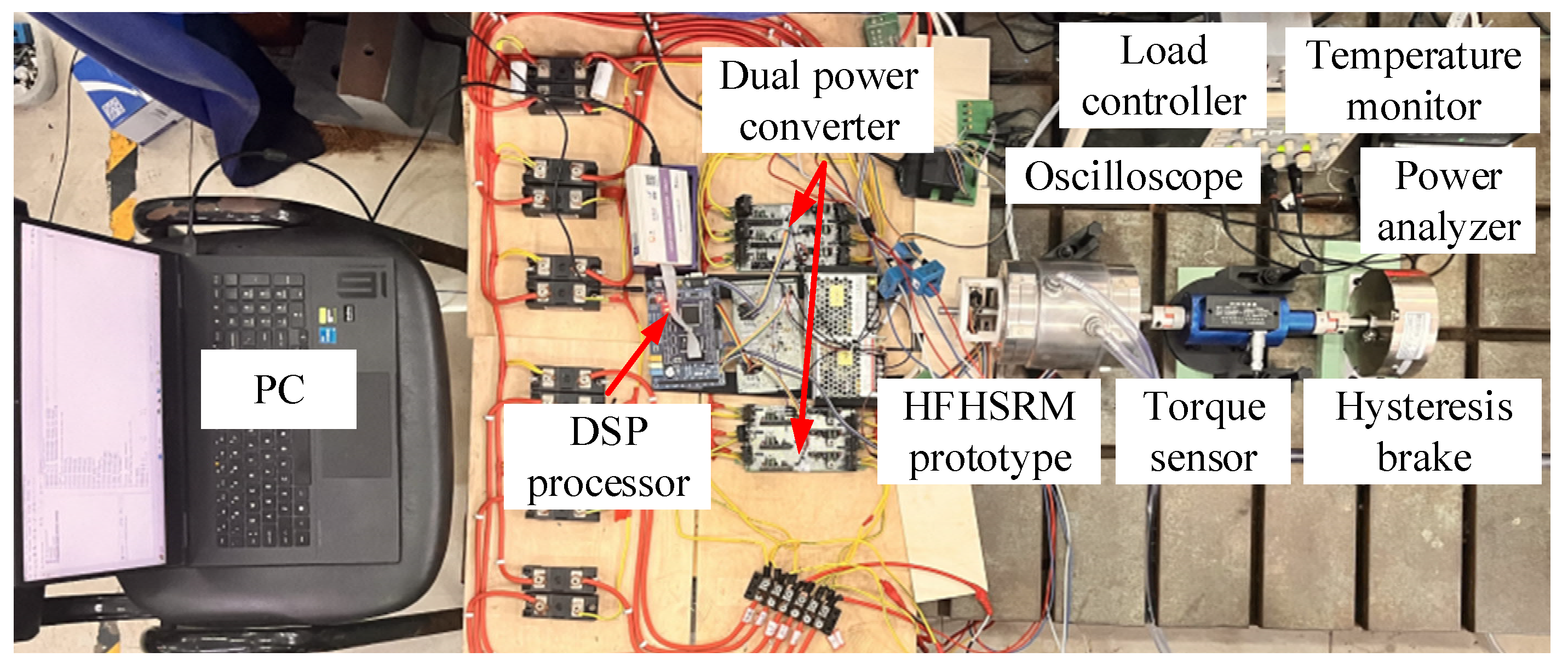
The dynamic experimental setup is shown in Figure 25. The prototype is driven by asymmetric half-bridge power converters controlled by a DSP, and the load is provided by a hysteresis brake, with braking torque adjusted via its DC excitation supply. During the tests, a standard current-regulated control strategy is adopted to track the prescribed current references. The same commutation angles and current references as those used in the simulations are applied in the DSP controller. The phase currents and torque are measured synchronously, and the waveforms are captured by an oscilloscope with a sampling rate of 2 GSa/s. The measured waveforms are shown in Figure 26 at n = 20,000 r/min and a single-side DC bus voltage, Vdc = 135 V.
To provide a unified evaluation of both the static and dynamic results, the error statistics of key electromagnetic quantities are summarized in Table 8. For the static results, the error is averaged over all sampled rotor angles within one pole pitch and all tested current levels. For the dynamic results, the error is evaluated over the steady-state interval after reaching periodic operation; mean torque is calculated over the same interval. The dynamic phase current error is calculated using one representative phase (Phase A), since the measured waveforms are nearly identical among phases under the adopted control strategy. Overall, the EMN exhibits slightly larger errors than the FEM. However, all EMN errors remain within 6%, indicating acceptable agreement with the experimental results. The errors are mainly attributed to experimental and manufacturing non-idealities (e.g., sensor noise, torque-chain vibration/misalignment, resistance variation, and assembly tolerances).

5. Conclusions

This paper addresses the 3D electromagnetic analysis of HFHSRMs. A quasi-3D parameterized EMN framework is established, and both numerical and experimental validations are conducted. The main conclusions are as follows:
(1)
Higher torque density is achieved by introducing permanent magnets into the axial magnetic circuit. In addition, rotor dislocation makes the resultant torque waveform smoother and reduces torque ripple, as predicted by the proposed EMN.
(2)
The EMN contains 13,776 elements (about 3.99% of the FEM mesh elements). The total computation time for one complete static characteristic simulation is reduced from 2.1 h (3-D FEM) to 0.1 h, and the peak memory usage is reduced from 21.5 GB to 2.3 GB, while the required accuracy is maintained.
(3)
With respect to prototype experiments, the EMN errors are 5.47% for static torque, 4.79% for static flux linkage, 4.59% for dynamic phase current, and 4.05% for dynamic mean torque; all errors are within 6%.
In future work, the proposed EMN will be extended to parameter optimization. Iron loss estimation will be integrated by using the EMN-predicted flux-density waveforms together with the established loss models, enabling rapid efficiency evaluation and system-level optimization of HFHSRMs.

Author Contributions

Conceptualization, L.Q. and A.L.; methodology, L.Q. and A.L.; software, L.Q.; validation, L.Q.; writing—original draft preparation, L.Q.; writing—review and editing, A.L.; project administration, A.L.; funding acquisition, A.L. All authors have read and agreed to the published version of the manuscript.

Funding

This research was funded by the National Natural Science Foundation of China, grant number 51777131. The APC was funded by Aimin Liu.

Institutional Review Board Statement

Not applicable.

Informed Consent Statement

Not applicable.

Data Availability Statement

The original contributions presented in this study are included in the article. Further inquiries can be directed to the corresponding author.

Conflicts of Interest

The authors declare no conflicts of interest.

References

  1. Palka, R. Operation of High-Speed Switched Reluctance Machines with a Non-Uniform Air Gap. Energies 2025, 18, 3033. [Google Scholar] [CrossRef] [Scilit]
  2. Davarpanah, G.; Faiz, J.; Shirzad, H. A C-Core Connected Two-Phase Switched Reluctance Motor with Embedded Permanent Magnets for Developed Torque Enhancement. IEEE Trans. Ind. Electron. 2024, 71, 2332–2342. [Google Scholar] [CrossRef] [Scilit]
  3. Lan, Y.Y.; Croonen, J.; Frikha, M.A.; Baghdadi, M.E.; Hegazy, O. A Comprehensive Performance Comparison between Segmental and Conventional Switched Reluctance Machines with Boost and Standard Converters. Energies 2023, 16, 43. [Google Scholar] [CrossRef] [Scilit]
  4. Yan, W.J.; Xin, J.; Zhang, K.; Chen, H.; Wang, Y.; Sun, X.Z.; Wang, Q. Torque Ripple Reduction of Double Stator Switched Reluctance Machine with Complementary Inner and Outer Stator Torques. IEEE Trans. Transp. Electrif. 2025, 11, 9602–9612. [Google Scholar] [CrossRef] [Scilit]
  5. Nasab, M.Z.; Afjei, E.; Davarpanah, G.; Ghaheri, A. An Innovative Hybrid Excited Switched Reluctance Motor for Enhanced Performance: Design, Analysis and Experimental Study. IEEE Trans. Transp. Electrif. 2025, 11, 9555–9567. [Google Scholar] [CrossRef] [Scilit]
  6. Qiu, H.B.; Yuan, C.W.; Chen, W.B.; Ma, X.L.; Xiong, B. Combined Regulation Performance Research of the Novel Flux-Torque Regulation Hybrid Excitation Machine with Axial-Radial Magnetic Circuit. IEEE Trans. Transp. Electrif. 2024, 10, 10420–10427. [Google Scholar] [CrossRef] [Scilit]
  7. Qiao, L.K.; Liu, A.M.; Ren, D.; Meng, F.G.; Wang, Y.C.; Liu, Y. Cooling System Design and Temperature Field Analysis for High-Speed Switched Reluctance Motor Considering Multi-Field Coupling of Electromagnetic-Thermal-Flow. IEEE Access 2025, 13, 77196–77209. [Google Scholar] [CrossRef] [Scilit]
  8. Bienkowski, K.; Łapczyński, S.; Szulborski, M.; Kozarek, Ł.; Gołota, K.; Cichecki, H.; Kolimas, Ł.; Żelaziński, T.; Smolarczyk, A.; Babiński, A.; et al. Validated Analytical Model of 8/6 and 10/8 Switched Reluctance Motors. Energies 2022, 15, 630. [Google Scholar] [CrossRef] [Scilit]
  9. Diao, K.K.; Sun, X.D.; Bramerdorfer, G.; Li, G.L.; Wang, Q.J.; Wu, L.J. A Novel Analytical Design Theory for Switched Reluctance Motors Incorporating Nonlinear Characteristics. IEEE Trans. Ind. Electron. 2025, 72, 6775–6785. [Google Scholar] [CrossRef] [Scilit]
  10. Chen, H.; Yan, W.J. Flux Characteristics Analysis of a Double-Sided Switched Reluctance Linear Machine Under the Asymmetric Air Gap. IEEE Trans. Ind. Electron. 2018, 65, 9843–9852. [Google Scholar] [CrossRef] [Scilit]
  11. Bian, Q.; Xia, C.Y.; Tian, L.S.; Wang, X.S.; Yu, Q. Electromagnetic Modeling of Nonlinear Features for a Canned Switched Reluctance Motor Using an FE-Assisted Fitting Network. J. Electr. Eng. Technol. 2025, 20, 5261–5272. [Google Scholar] [CrossRef] [Scilit]
  12. Sun, H.T.; He, Z.Y.; Deng, X.; Chen, Y.; Lee, W.K. Comparative Study of Switched Reluctance Motor Drives with Ring and Tail Topologies. IEEE Trans. Ind. Electron. 2025, 72, 9889–9899. [Google Scholar] [CrossRef] [Scilit]
  13. Wang, J.Y.; Zhu, Y.Y.; Xing, C.; Liu, X.; Lin, Y.E. Multi-Indicator Synchronous Optimization Design Method for SRM Based on Electromagnetic–Thermal Coupling and Actual Vehicle Driving Conditions. IEEE Trans. Transp. Electrif. 2025, 11, 8512–8522. [Google Scholar] [CrossRef] [Scilit]
  14. Hua, H.; Hua, W. Analytical Prediction of Torque of Switched Reluctance Machines Considering Nonlinear Characteristics. IEEE Trans. Ind. Electron. 2022, 69, 190–201. [Google Scholar] [CrossRef] [Scilit]
  15. Souissi, A.; Abdennadher, I.; Masmoudi, A. Analytical Investigation of the Air Gap Flux Density of Surface-Mounted PMSMs with Irregular Pole Shapes. IEEE Trans. Ind. Electron. 2025, 72, 198–210. [Google Scholar] [CrossRef] [Scilit]
  16. Kumar, A.; Marwaha, S.; Manna, M.S. Design and Parametric Analysis of Switched Reluctance Motor Using Adaptive FEA for Torque Ripple Reduction. Int. J. Power Energy Conv. 2022, 13, 209–223. [Google Scholar] [CrossRef] [Scilit]
  17. Karban, P.; Pánek, D.; Kaska, J. Open-Source Platform for Simulation of Physical Fields: Agros. J. Comput. Appl. Math. 2025, 465, 116589. [Google Scholar] [CrossRef] [Scilit]
  18. Davarpanah, G.; Faiz, J. Nonlinear Modeling of a C-Core Connected Two-Phase Switched Reluctance Motor. IEEE Trans. Energy Convers. 2021, 36, 2761–2769. [Google Scholar] [CrossRef] [Scilit]
  19. Liu, G.H.; Jiang, S.; Zhao, W.X.; Chen, Q. A New Modeling Approach for Permanent Magnet Vernier Machine with Modulation Effect Consideration. IEEE Trans. Magn. 2017, 53, 1–13. [Google Scholar] [CrossRef] [Scilit]
  20. Cheng, M.; Xu, Z.Y.; Zhang, G. Vector Magnetic Circuit Based Equivalent Magnetic Network for Flux-Switching Permanent Magnet Machines. IEEE Trans. Energy Convers. 2025, 40, 1517–1528. [Google Scholar] [CrossRef] [Scilit]
  21. Zhu, X.K.; Qi, G.Y.; Cheng, M.; Qin, W.; Liu, Y.B.; Huang, J.W. Equivalent Magnetic Network Model of Electrical Machine Based on Three Elements: Magnetic Flux Source, Reluctance, and Magductance. IEEE Trans. Transp. Electrif. 2025, 11, 3538–3548. [Google Scholar] [CrossRef] [Scilit]
  22. Watthewaduge, G.; Bilgin, B. Radial Force Density Calculation of Switched Reluctance Machines Using Reluctance Mesh-Based Magnetic Equivalent Circuit. IEEE Open J. Ind. Electron. Soc. 2021, 3, 37–49. [Google Scholar] [CrossRef] [Scilit]
  23. Watthewaduge, G.; Bilgin, B. Reluctance Mesh-Based Magnetic Equivalent Circuit Modeling of Switched Reluctance Motors for Static and Dynamic Analysis. IEEE Trans. Transp. Electrif. 2022, 8, 2164–2176. [Google Scholar] [CrossRef] [Scilit]
  24. Zhu, X.G.; Liu, Z.M.; Liu, G.H.; Ke, H.; Du, K.K.; Xu, L. General Equivalent Magnetic Network Model of Surface-Mounted Permanent Magnet Vernier Machine Based on Hybrid Medium Mesh. Proc. Chin. Soc. Electr. Eng. 2024, 44, 2009–2019. [Google Scholar] [CrossRef]
  25. Wu, J.C.; Wang, S.; Hu, Y.; Zhang, B.Y.; Xu, X.F. Modeling and Analysis of Quasi-3D Equivalent Magnetic Network of Direct-Drive Inner Boost Permanent Magnet Motor. IEEE Access 2025, 13, 304–315. [Google Scholar] [CrossRef] [Scilit]
  26. Jiang, S.X.; Peng, B. Development of Universal 3D Equivalent Magnetic Network Model for YASA Axial Flux Permanent Magnet Motor Using Edge Step Equivalent Method. Trans. China Electrotech. Soc. 2025, online ahead of print. [Google Scholar] [CrossRef]
  27. Zhang, Z.Y.; Li, B.; Ma, X.C.; Li, G.D.; Gao, P. An Adaptive Connecting Equivalent Magnetic Network Considering Local Magnetic Characteristics for SPM Motors. Int. J. Circuit Theory Appl. 2025, 53, 5989–5999. [Google Scholar] [CrossRef] [Scilit]
  28. Ding, L.; Liu, G.H.; Chen, Q.; Xu, G.H. A Novel Mesh-Based Equivalent Magnetic Network for Performance Analysis and Optimal Design of Permanent Magnet Machines. IEEE Trans. Energy Convers. 2019, 34, 1337–1346. [Google Scholar] [CrossRef] [Scilit]
  29. Wang, S.S.; Liu, Z.Y.; Deng, Z.Q.; Zhou, A.M. Mathematical Fitting of Coupling Dynamic and Static Inductance for a Bearingless Switched Reluctance Motor. Trans. China Electrotech. Soc. 2007, 22, 22–28. [Google Scholar] [CrossRef]
  30. Watthewaduge, G.; Sayed, E.; Emadi, A.; Bilgin, B. Electromagnetic Modeling Techniques for Switched Reluctance Machines: State-of-the-Art Review. IEEE Open J. Ind. Electron. Soc. 2020, 1, 218–234. [Google Scholar] [CrossRef] [Scilit]
  31. Dowlatshahi, M.; Saghaiannejad, S.M.; Ahn, J.W.; Moallem, M. Minimization of Torque-Ripple in Switched Reluctance Motors Over Wide Speed Range. J. Electr. Eng. Technol. 2014, 9, 478–488. [Google Scholar] [CrossRef] [Scilit]
Figure 1. The topology and main magnetic flux path of the HFHSRM with rotor dislocation. (a) The topology of the HFHSRM; (b) main magnetic flux path and rotor dislocation (15°).
Actuators 15 00174 g001
Figure 2. Schematic torque waveforms of the HFHSRM. (a) NRD; (b) RD.
Actuators 15 00174 g002
Figure 3. Comparison of motor torque between NRD and RD.
Actuators 15 00174 g003
Figure 4. Basic cross-shaped mesh elements.
Actuators 15 00174 g004
Figure 5. Overall EMN topology partition (one side shown).
Actuators 15 00174 g005
Figure 6. Branch and node numbering rules.
Actuators 15 00174 g006
Figure 7. Stator EMN model.
Actuators 15 00174 g007
Figure 8. Rotor EMN model.
Actuators 15 00174 g008
Figure 9. Air-gap EMN model.
Actuators 15 00174 g009
Figure 10. Axial coupling branches in the EMN.
Actuators 15 00174 g010
Figure 11. Circumferential node shift for rotor dislocation in the EMN.
Actuators 15 00174 g011
Figure 12. Piecewise fitting curves of the core material.
Actuators 15 00174 g012
Figure 13. Flowchart of the nonlinear EMN solution procedure over the (θ, i) grid.
Actuators 15 00174 g013
Figure 14. 3D FEM model and mesh of the HFHSRM.
Actuators 15 00174 g014
Figure 15. Air-gap flux density at the aligned position. (a) Left-side air gap; (b) right-side air gap.
Actuators 15 00174 g015
Figure 16. Comparison of flux linkage characteristics.
Actuators 15 00174 g016
Figure 17. Magnetization curves at aligned/unaligned positions for HFHSRM and HFHSRM-NoPM.
Actuators 15 00174 g017
Figure 18. Comparison of inductance characteristics.
Actuators 15 00174 g018
Figure 19. Comparison of static torque characteristics.
Actuators 15 00174 g019
Figure 20. Comparison of dynamic results. (a) Phase-A current waveform; (b) torque waveform.
Actuators 15 00174 g020
Figure 21. Accuracy–efficiency trade-off under different Nag.
Actuators 15 00174 g021
Figure 22. Prototype experimental platform for static tests.
Actuators 15 00174 g022
Figure 23. Comparison of static torque characteristics among EMN, FEM, and experiment.
Actuators 15 00174 g023
Figure 24. Comparison of static incremental flux linkage characteristics.
Actuators 15 00174 g024
Figure 25. Prototype experimental platform for dynamic tests.
Actuators 15 00174 g025
Figure 26. Measured waveforms of phase currents and torque.
Actuators 15 00174 g026
Table 1. Key electromagnetic and structural parameters of the HFHSRM.
SymbolsValue
Rated power PN (kW)3
Rated speed nN (r/min)20,000
Rated voltage UN (V)270
Stator/rotor pole Ns/Nr6/4
Stator/rotor pole arc βs/βr (°)32/30
Stator/rotor outer diameter Ds/Dr (mm)105/50
Rotor inner diameter Dr1 (mm)18.5
Air-gap length g (mm)0.4
Core length (one side) La (mm)20.5
Permanent magnet length Lm (mm)3
Stator/rotor magnetic bridge length Ls/Lr (mm)13.5/30
Stator/rotor yoke height hsy/hry (mm)8.8/8.9
Winding turns per pole per phase Nc43
Table 2. μr(B) update performance: piecewise fitting vs. direct interpolation under different Nag.
MethodNagAverage IterationsRuntime (s)Non-Convergent Cases
Piecewise fitting7213174.311
144124120.842
216131184.243
288130234.195
360137301.075
Direct interpolation72168112.6315
144188174.5321
216174234.0418
288188315.8520
360189393.4021
Table 3. Relative error of flux linkage under different currents.
Current (A)Error (%)
02.49
42.99
83.59
123.88
164.07
205.07
246.82
Average4.13
Table 4. Relative error of inductance under different currents.
Current (A)Error (%)
01.63
41.55
81.63
122.58
163.22
203.62
246.51
Average2.96
Table 5. Relative error of static torque under different currents.
Current (A)Error (%)
44.90
84.24
123.43
162.91
202.39
242.16
Average3.34
Table 6. Comparison of mean torque and torque ripple.
ParameterEMNFEM
Tave (N·m)1.421.44
δT (%)58.7464.91
Table 7. Comparison of model size and computational resources.
MethodNumber of ElementsComputation TimePeak RAM
Quasi-3D EMN13,7760.1 h2.3 GB
3D FEM344,9682.1 h21.5 GB
Table 8. Summary of errors relative to experimental results.
QuantityError to Experiment (%)
EMNFEM
Static torque5.473.68
Static flux linkage4.793.73
Dynamic phase current4.593.77
Dynamic torque (mean)4.052.71
Disclaimer/Publisher’s Note: The statements, opinions and data contained in all publications are solely those of the individual author(s) and contributor(s) and not of MDPI and/or the editor(s). MDPI and/or the editor(s) disclaim responsibility for any injury to people or property resulting from any ideas, methods, instructions or products referred to in the content.