


Abstract
During laser processing, optimizing the cutting performance by adjusting the angle or off-axis displacement between the auxiliary gas flow and the laser beam is an effective approach to improving processing quality and efficiency. However, traditional electromechanical actuators suffer from inherent limitations in compactness and multi-degree-of-freedom cooperative control, which restrict their applicability in high-speed and high-precision laser cutting systems. To address these limitations, this paper presents a five-degree-of-freedom magnetic levitation actuator for laser cutting lens control and proposes a multi-degree-of-freedom cooperative control strategy based on backstepping control (BC) to cope with the system’s strong coupling, nonlinearity, and model uncertainty. First, a dynamic model of the actuator system is established, and a corresponding BC is designed. Subsequently, a centralized control framework is developed, and comparative simulations and experiments are carried out between the proposed BC and a conventional PID controller. The experimental results demonstrate that the proposed BC method outperforms the PID controller in terms of multi-degree-of-freedom cooperative control capability and dynamic response, thereby significantly enhancing the overall control performance of the system.
1. Introduction
With increasing demands in modern manufacturing for geometric precision, surface quality, and micrometer-level dimensional control, laser cutting technology has been widely adopted because of its non-contact operation, high precision, and efficiency [1,2,3]. However, when processing complex curved or irregularly shaped workpieces, the structural complexity and limited degrees of freedom of conventional contact-based drive mechanisms hinder precise and efficient motion control in arbitrary directions.
Magnetic levitation actuators offer clear advantages for multi-degree-of-freedom precision motion control due to their frictionless, contamination-free operation, fast response, and capability for real-time active control [4]. Compared with traditional contact-based actuators, their compact structure and superior dynamic performance make them promising for high-precision applications such as lens positioning in laser cutting systems [5,6,7]. Nevertheless, achieving robust multi-degree-of-freedom control for magnetic levitation systems remains challenging because of strong coupling, nonlinearity, and parameter uncertainties. Although PID control is widely used for its simplicity and ease of tuning, it generally exhibits a limited robustness against external disturbances and model uncertainties [8,9,10].
To improve control performance, researchers have explored various advanced strategies. The linear active disturbance rejection control (ADRC) methods proposed in [11,12] enhance disturbance rejection capabilities. The sliding mode control strategies in [13,14] significantly improve dynamic performance and stability. Adaptive feedback methods based on Lyapunov theory [15,16] further increase robustness within the operating bandwidth. While these approaches can improve system stability to some extent, they often involve complicated parameter tuning or lengthy derivations, which limits their adaptability in complex application scenarios. Therefore, backstepping control (BC) has been introduced into magnetic levitation systems to simplify parameter tuning and enhance robustness [17,18]. For example, Yang [19] proposed an adaptive backstepping strategy with state constraints for active magnetic bearings and validated its stability and effectiveness through simulations and experiments. Xu [20] introduced a fractional-order adaptive backstepping method for segmented rotor vibration suppression, achieving a superior suppression performance. Rong [21] combined adaptive backstepping with sliding mode control to mitigate zero-bias current uncertainties in active magnetic bearings and experimentally verified its effectiveness. Zhu [22] integrated flux feedback with adaptive BC to suppress vehicle–track coupled vibration instability, demonstrating a robust suspension performance under low track stiffness.
Although previous studies have introduced BC into magnetic levitation systems and validated its effectiveness in single-degree-of-freedom or specific application scenarios, research addressing both multi-degree-of-freedom control and dynamic performance enhancement for compact multi-degree-of-freedom magnetic levitation actuators tailored for laser processing remains relatively limited. The existing related work has primarily focused on structural design or single-axis positioning functions. For instance, the hollow coil drive unit proposed by He [6] only achieved real-time radial positioning without exploring multi-degree-of-freedom cooperative control. Zhang [7] improved machining accuracy through sensor offset compensation but did not address enhancements to system dynamic characteristics. Furthermore, the experimental results from the authors’ prior work [5] based on single-degree-of-freedom PID control indicate that significant overshoot and slow response remain issues in magnetic levitation drive systems, further underscoring the necessity for multi-degree-of-freedom control research.
Accordingly, this paper proposes a multi-degree-of-freedom backstepping control method for a five-degree-of-freedom magnetic levitation actuator intended for laser cutting lens control. We linearize the electromagnetic force about the operating point to derive the actuator’s dynamic model and design the BC based on that model. Simulation and experimental comparisons with conventional PID control demonstrate that the proposed method improves tracking accuracy and dynamic response.
2. System Description
2.1. System Structure and Working Principle
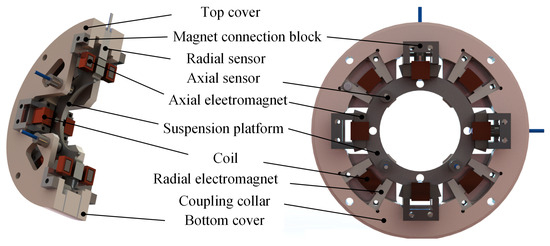
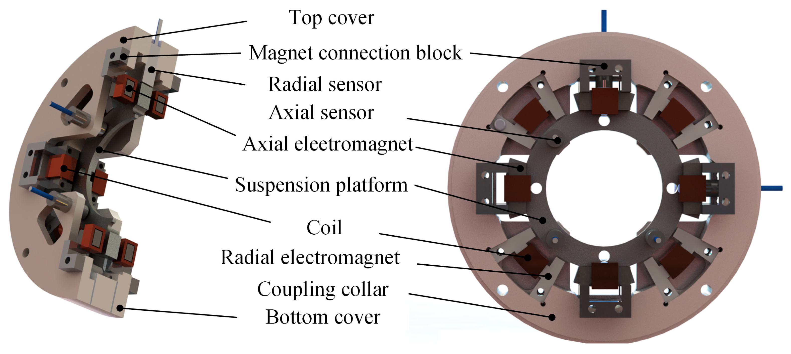
The structure of the five-degree-of-freedom magnetic levitation drive device is illustrated in Figure 1. The device consists of three main components: an upper cover, a connecting ring, and a lower cover. The upper and lower end caps, which are made of aluminum, are equipped with four sets of differential axial electromagnets and corresponding axial displacement sensors to achieve precise axial position control of the magnetic levitation drive system. These differential axial electromagnets are uniformly distributed along the circumference of the upper and lower end caps through aluminum magnet connection blocks. Eddy current displacement sensors are employed as axial sensors, with three sensors embedded in the upper cover and arranged at 45° relative to the axial electromagnets. The axial air gap is calculated based on the measured distance between the eddy current sensors and the suspension platform, together with the initial air gap.
Figure 1.
Five-degree-of-freedom magnetic levitation actuator structure.
The connecting ring, also made of aluminum, integrates radially arranged electromagnets and displacement sensors in a differential configuration to provide radial control. The suspension platform is coaxially aligned with the connecting ring to ensure radial stability. The radial electromagnets are fixed to the connecting ring using nuts, and four sets of differential radial electromagnets are evenly distributed around its circumference. Eddy current displacement sensors are also used for radial position measurement. Two radial sensors are embedded in the connecting ring, positioned perpendicular to each other and oriented at 45° relative to the radial electromagnets. Similarly, the radial air gap is determined from the measured distance between the sensor probes and the suspension platform, along with the initial air gap condition.
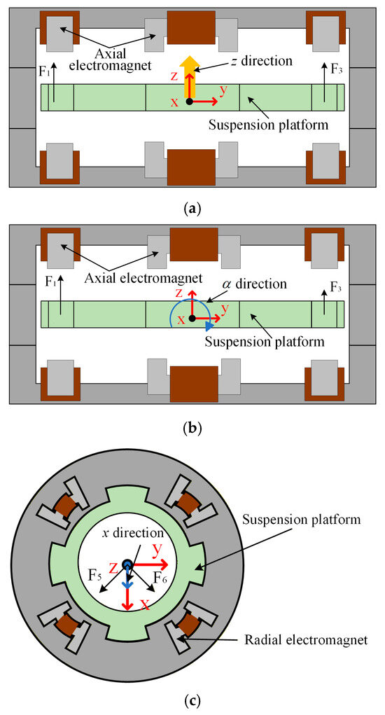
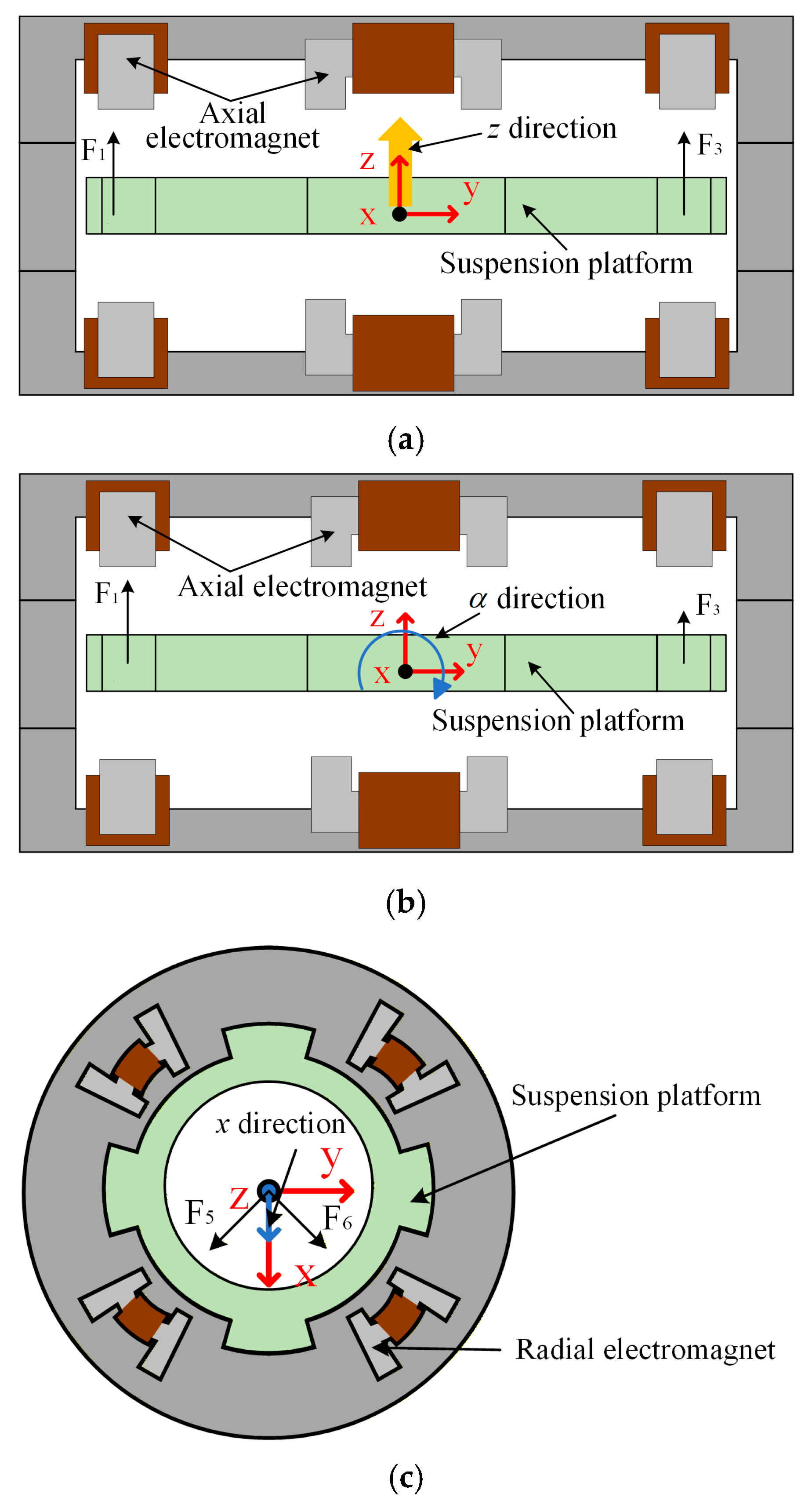
The working principle of the magnetic levitation actuator is illustrated in Figure 2. Owing to the structural symmetry of the five-degree-of-freedom magnetic levitation drive, the operating principles of the α and β degrees of freedom, as well as the x and y degrees of freedom, are analogous. Therefore, this paper focuses on the operating principles of the z, α, and x degrees of freedom for illustration.
Figure 2.
Motion control principle of suspended platform. (a) z direction working principle; (b) α direction working principle; (c) x direction working principle.
The working principle of the z degree of freedom in the magnetic levitation actuator is illustrated in Figure 2a. The resultant force generated by four sets of differential axial electromagnets in the vertical direction causes the levitation platform to translate along the positive z-axis, achieving directional motion in the z degree of freedom. The operating principle of the α degree of freedom in the magnetic levitation drive is shown in Figure 2b. Two sets of axial electromagnets generate torques in opposite directions, causing the levitation platform to rotate clockwise around the X-axis, thereby achieving rotational motion in the α degree of freedom. The working principle of the X-axis degree of freedom in the magnetic levitation driver is shown in Figure 2c. The resultant force generated by two sets of differential axial electromagnets in the radial direction causes the levitation platform to translate along the positive X-axis direction, achieving directional motion in the X-axis degree of freedom.
2.2. System Dynamics Model
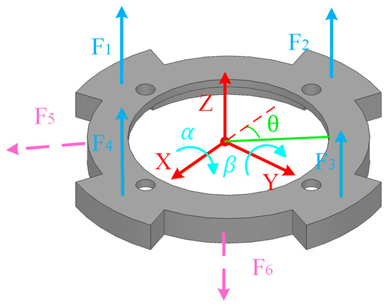
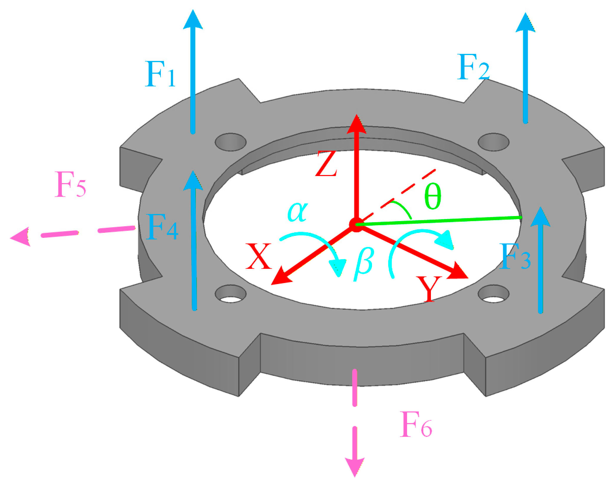
The forces and motions of the 5-DOF magnetic levitation actuator are illustrated in Figure 3. By analyzing the forces and motions associated with each degree of freedom, the corresponding differential equations are derived as follows:
Figure 3.
Force analysis of the suspended platform in a magnetic levitation actuator.
Performing a Taylor expansion of the electromagnetic force F at the equilibrium position (x0, i0) of the system and discarding higher-order terms, the electromagnetic force F(x0, i0) can be expressed as
Among these, k = 1/4µ0N2Aa, Ki = 4ki0/x0, and Kd = 4ki02/x03; Ki denotes the current stiffness coefficient; Kd represents the unit displacement stiffness coefficient; µ0 is the vacuum permeability; N is the number of turns in a single electromagnet coil; Aa is the cross-sectional area of the iron core in a single electromagnet; i0 is the bias current; i is the current in the electromagnet coil; and x0 is the air gap between the electromagnet pole and the suspended object. The dynamic model parameters of the five-degree-of-freedom magnetic levitation drive are shown in Table 1.
Table 1.
Model parameters.
Substituting Equation (2) into Equation (1) yields
In the above equation, F1, F2, F3, and F4 represent the electromagnetic forces generated by the four sets of axial electromagnets; F5 and F6 represent the electromagnetic forces generated by the two sets of radial electromagnets; the control currents for the five degrees of freedom are denoted by uz, uα, uβ, ux, and uy, respectively; Ki is the current stiffness coefficient; Kd is the displacement stiffness coefficient; θ denotes the angle between the sensor and the X-axis; and L2 is the distance from the center to the axial electromagnet. The variables z, α, and β refer to the displacements of the levitated platform along the Z-axis, the angle of rotation around the X-axis, and the angle of rotation around the Y-axis, respectively. Similarly, x and y denote the displacements along the X-axis and Y-axis, respectively. The mass of the levitated platform is denoted by m. The damping coefficients for the five degrees of freedom are represented by cz, cα, cβ, cx, and cy. The external perturbations for the five degrees of freedom are given by fz, fx, fy, Tα, and Tβ. Finally, Jα and Jβ denote the moments of inertia around the X-axis and Y-axis, respectively.
3. Backstepping Controller Design and Simulation Analysis
3.1. Backstepping Controller Design
For brevity, “backstepping control” is abbreviated as BC. Equation (2) represents the linearized dynamics model. To facilitate an understanding of the BC design process, the z BC is used as an example. First, the state-space equations are rewritten in strict feedback form as follows:
Rearrange Equation (3) into matrix form:
where
First, define the z degree of freedom tracking error as
where z1ref is the desired displacement trajectory. The Lyapunov function is chosen as follows:
Calculate the derivative of (4) as follows:
Considering z2 as a virtual control quantity, the desired virtual control z2ref is
where k1 is a positive number and k1e1 denotes the virtual control law in the first subsystem. Summing Equation (6) into Equation (5) yields
According to Lyapunov’s theorem, the system is asymptotically stable when V1 > 0 and , indicating that the suspended platform displacement can track the desired displacement.
The error between the virtual control z2 and the desired virtual control z2ref can be obtained through Equation (7) as
Select the Lyapunov function V2:
Calculate the derivative of (14) as follows:
Substituting Equations (7), (10) and (12) into Equation (15) yields
According to Lyapunov’s theorem, in order to stabilize the system,
where k1 > 0, k2 > 0. The system is asymptotically stable when V2 > 0, .
Bringing Equations (4) and (10) into Equation (13), the control law uz for the z degree of freedom is given by
The above is the derivation of the BC rate for the z, which is similar for the other degrees of freedom.
3.2. Simulation Analysis
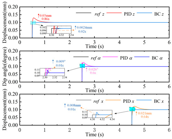
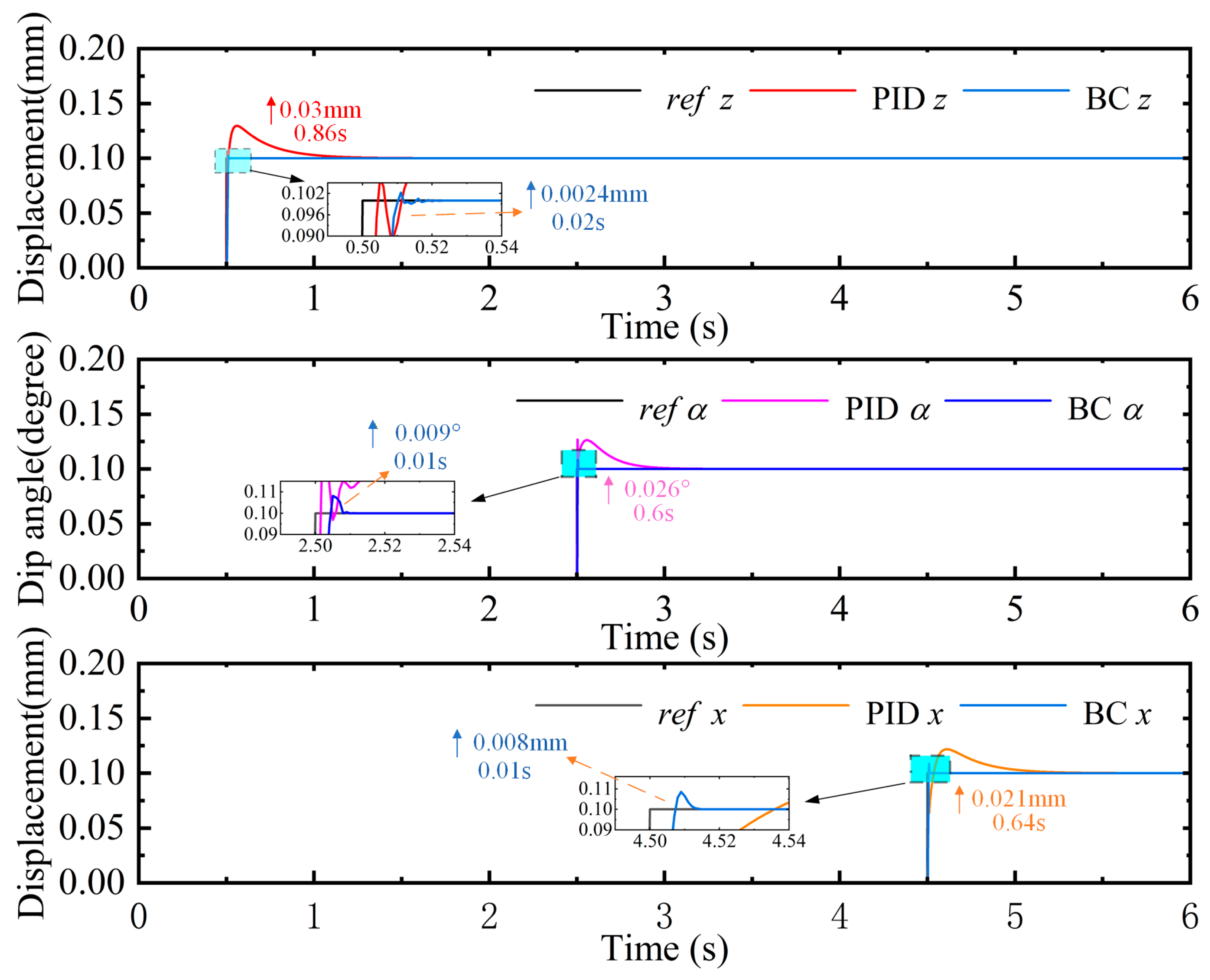
To evaluate the dynamic performance of the proposed BC method, numerical simulations were conducted based on the established dynamic model of the five-degree-of-freedom magnetic levitation actuator. The simulation sampling period was set to 0.001 s, consistent with the actual system. To assess the controller’s performance, both BC and PID control strategies were implemented in the magnetic levitation drive system. Their response speed and overshoot suppression capabilities under step input signals were compared using simulation software.
Owing to the structural symmetry of the actuator, three representative degrees of freedom—z, α, and x—were selected for simulation analysis. The initial position of the levitated platform was set to (0 mm, 0°, 0 mm), and the target equilibrium position was set to (0.1 mm, 0°, 0 mm). As shown in Figure 4, step inputs were applied sequentially at 0.5 s, 2.5 s, and 4.5 s to the z, α, and x directions, respectively, and the corresponding system responses under both control strategies were compared.
Figure 4.
Step response simulation for PID and BC.
When a 0.1 mm step input was applied to the z direction at 0.5 s, the BC exhibited a maximum overshoot of 24% and stabilized within approximately 0.02 s, while the PID controller showed a significantly higher overshoot of 30% with a settling time of around 0.86 s. When a 0.1° step input was applied to the α direction at 2.5 s, the BC achieved an overshoot of 9% and stabilized within 0.25 s, whereas the PID controller exhibited an overshoot of 26% and a settling time of approximately 0.6 s. Finally, for a 0.1 mm step input applied to the x direction at 4.5 s, the BC achieved a minimal overshoot of 8% with a fast response time of 0.01 s, compared to a 21% overshoot and 0.64 s settling time for the PID controller.
The simulation results demonstrate that the BC exhibits an excellent dynamic response performance within the operating range, significantly improving the dynamic performance of the five-degree-of-freedom magnetic levitation actuator. However, due to certain idealized conditions in the simulation, these results may not be fully applicable to actual complex operating conditions. Furthermore, issues such as sensor noise and mechanical defects may arise in the experimental system, necessitating further validation and optimization in conjunction with the actual system.
4. Experimentation and Analysis
4.1. Experimental System
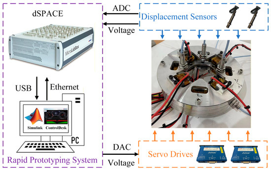
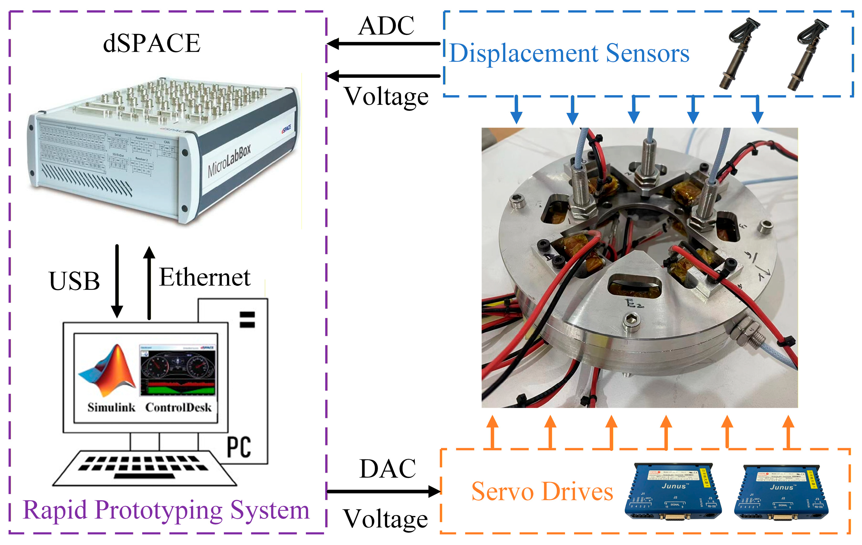
The five-degree-of-freedom magnetic levitation drive experimental system primarily consists of a five-degree-of-freedom magnetic levitation drive, a control system, a displacement detection system, and a power amplifier, as shown in Figure 5. The control system is based on the DS1202 control board developed by dSPACE (Paderborn, Germany). The host computer is equipped with the ControlDesk 7.6 software toolkit. The displacement detection system employs eddy current displacement sensors for air gap measurement. The air gap or displacement is converted into an analog voltage signal by the eddy current sensor preamplifier, which is then fed back to the control system. In this experiment, the controller’s sampling frequency is set to 1 kHz.
Figure 5.
Five-degree-of-freedom magnetic levitation actuator experiment system.
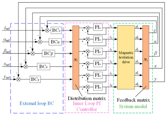
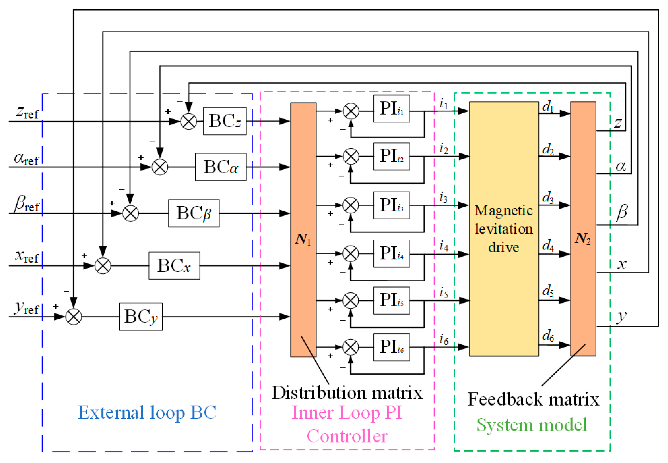
To validate the accuracy of the simulation results, multi-degree-of-freedom control experiments were conducted on a five-degree-of-freedom magnetic levitation drive system using both PID and BC strategies. The centralized control block diagram for the PID and BC in the experiment is shown in Figure 6. The system model of the five-degree-of-freedom magnetic levitation drive comprises a five-degree-of-freedom motion model and electromagnetic coil models for each group. The control system block diagram adopts a dual-loop control structure. The five degrees of freedom of the levitation platform serve as the controlled variable for the outer loop. This outer loop employs either a BC or an adaptive controller, forming the position regulation loop of the control system. The inner loop utilizes a PI current loop. This design enables the output current to rapidly track the output voltage of the levitation controller within a specific frequency range, thereby enhancing the stable levitation performance of the five-degree-of-freedom magnetic levitation drive system.
Figure 6.
Experimental system control structure block diagram.
4.2. Axial Multi-Degree-of-Freedom Control
To further promote the engineering applications of magnetic levitation drives in laser processing equipment—such as shaped hole machining and complex trajectory cutting—it is essential to achieve a coordinated multi-degree-of-freedom control of the platform.
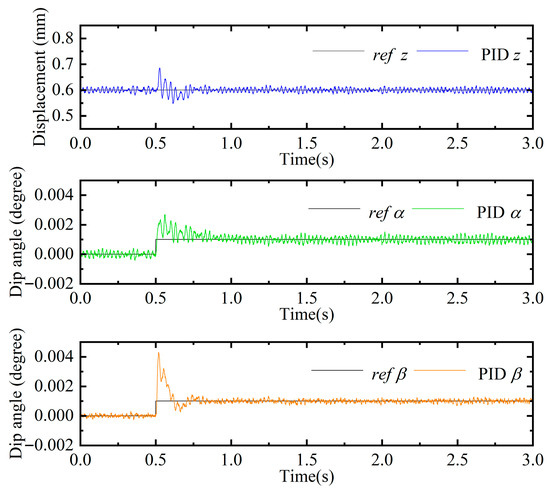
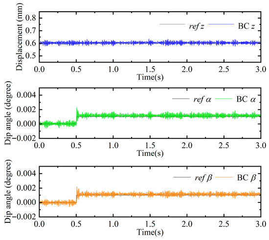
Therefore, this paper conducts multi-degree-of-freedom control experiments on a five-degree-of-freedom magnetic levitation actuator prototype to verify the control strategy’s response characteristics and effectiveness under coupled interference conditions. Initially, the controller stabilized the levitated platform at the equilibrium position (0.6 mm, 0°, 0°). At 0.5 s, a 0.001° step input was simultaneously applied to the α and β degrees of freedom, while the response of the z degree of freedom was recorded.
Figure 7 illustrates the multi-degree-of-freedom control response of the PID controller following the step input. The maximum overshoot reached 160% for the α degree of freedom, with a response time of 0.52 s, and 320% for the β degree of freedom, with a response time of 0.36 s. Due to coupling effects, the z degree of freedom was perturbed but returned to equilibrium within approximately 0.25 s, indicating a sensitivity to dynamic disturbances. In contrast, Figure 8 shows the axial multi-degree-of-freedom response under the BC strategy. The maximum overshoots of the α and β degrees of freedom were reduced to 120% and 115%, respectively, with response times significantly shortened to 0.05 s and 0.07 s. The z degree of freedom was nearly unaffected by attitude perturbations, demonstrating a stronger anti-coupling capability. However, under BC, small high-frequency oscillations appeared in the response curves, along with some steady-state error. The primary reason is that increasing the backward control gains can significantly accelerate the dynamic response of multi-degree-of-freedom systems. However, excessively high gains amplify measurement noise and unmodeled dynamics, particularly due to the inclusion of displacement signal derivative terms in the control law, which can induce high-frequency oscillations or even flutter.
Figure 7.
PID axial multi-degree-of-freedom step response experiment.
Figure 8.
BC axial multi-degree-of-freedom step response experiment.
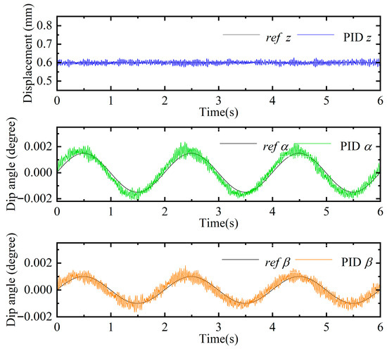
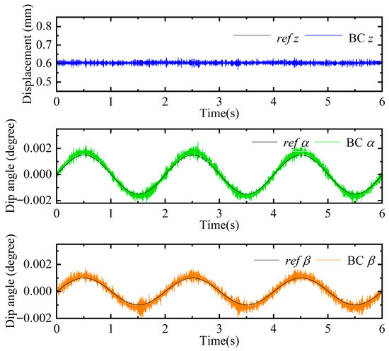
To further analyze the dynamic performance of the inverse step controller in the experimental coordinated control of the axial multi-degree-of-freedom system for the magnetic levitation drive, sinusoidal signals of identical frequency but varying amplitudes were simultaneously applied. A comparative simulation analysis was conducted to examine the multi-degree-of-freedom sinusoidal tracking responses between the PID controller and the inverse step controller. Similarly, the suspension platform was first stabilized at the equilibrium position (0.6 mm, 0°, 0°). Subsequently, sinusoidal signals with amplitudes of 0.0015° and 0.001° and a frequency of 0.5 Hz were simultaneously applied to the α and β degrees of freedom, respectively. The responses of α and β were recorded, along with the response of the z degree of freedom, as shown in Figure 9 and Figure 10.
Figure 9.
PID axial multi-degree-of-freedom sine response experiment.
Figure 10.
BC axial multi-degree-of-freedom sine response experiment.
Figure 9 shows the multi-degree-of-freedom control responses of α and β under PID control following a sinusoidal input signal. The figure shows that the output-to-input amplitude ratio for the α degree of freedom is approximately 1.09, with the output response phase lagging the sinusoidal input by 9°. For the β degree of freedom, the output-to-input amplitude ratio is approximately 1.21, with the output response phase lagging the sinusoidal input by 12.6°. After applying sinusoidal signals to both the α and β degrees of freedom, the α degree of freedom does not affect the z degree of freedom. Figure 10 shows the multi-degree-of-freedom control responses of α and β under the BC controller following a sinusoidal input signal. The figure shows that the output-to-input amplitude ratio for the α degree of freedom is approximately 1.13, with the output response phase lagging the sinusoidal input by 0°; the output-to-input amplitude ratio for the β degree of freedom is approximately 1.19, with the output response phase lagging the sinusoidal input by 0°. Furthermore, after applying sinusoidal signals to both the α and β degrees of freedom, the α degree of freedom does not affect the z degree of freedom.
In summary, this paper compares the dynamic performance of PID control and BC in a five-degree-of-freedom magnetic levitation actuator system through axial multi-degree-of-freedom step and sine response experiments. The experimental results demonstrate that the BC method outperforms PID control overall, effectively enhancing the system’s dynamic response capability across multiple degrees of freedom. Specifically, while PID control achieves stable step and sine wave tracking, it exhibits prolonged settling times, significant overshoot, and a susceptibility to phase lag and coupled disturbances. Conversely, BC offers advantages such as rapid response and superior dynamic characteristics, but it is prone to introducing steady-state error. Furthermore, improper parameter selection may trigger system oscillations or even lead to divergence.
4.3. Radial Multi-Degree-of-Freedom Control
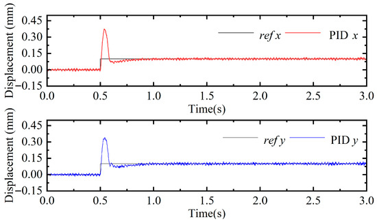
To further evaluate the dynamic performance of multi-degree-of-freedom control in the translational direction, a simultaneous step input of 0.1 mm is applied to both the x and y degrees of freedom while the platform is stabilized at the equilibrium position (0.6 mm, 0°, 0°, 0 mm, 0 mm).
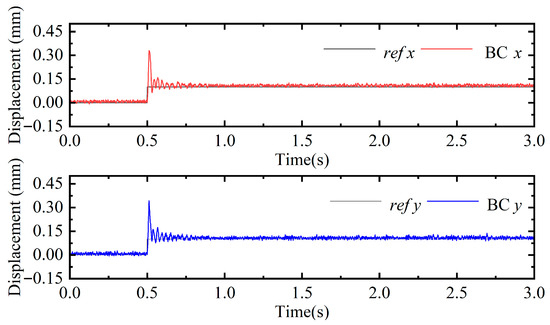
Figure 11 and Figure 12 illustrate the radial multi-degree-of-freedom control responses under PID and BC strategies, respectively. As shown in Figure 11, the x degree of freedom exhibits a maximum overshoot of 270% with a response time of approximately 0.50 s, while the y degree of freedom shows an overshoot of 240% and a response time of about 0.55 s. The system response demonstrates significant hysteresis and is strongly affected by coupling interference among the degrees of freedom. In contrast, Figure 12 shows a marked improvement in response speed under BC. The x and y degrees of freedom exhibit overshoots of 220% and 230%, with response times of 0.15 s and 0.29 s, respectively. Compared with PID control, BC achieves a faster response and more effective suppression of large oscillations. However, Figure 12 shows amplitude spikes appearing in the response as the signal changes. These spikes primarily result from the system employing a high control gain to ensure closed-loop stability in the presence of external disturbances and measurement noise. When the reference signal changes rapidly, the high gain temporarily amplifies the control input, causing transient amplitude spikes.
Figure 11.
PID radial multi-degree-of-freedom step response experiment.
Figure 12.
BC radial multi-degree-of-freedom step response experiment.
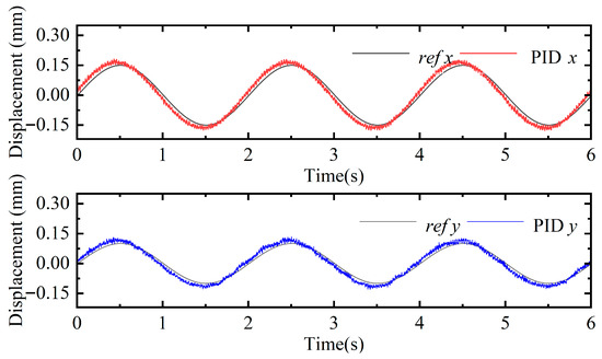
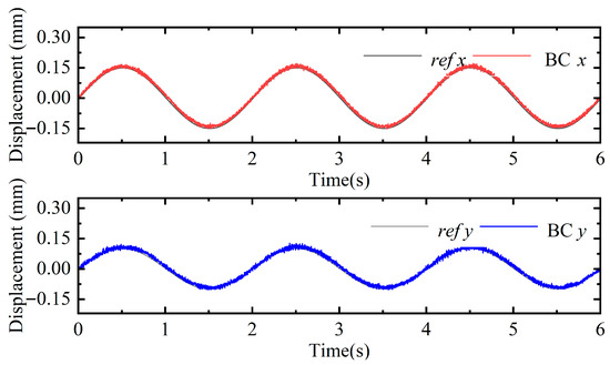
Similarly, to further analyze the dynamic performance of radial multi-degree-of-freedom coordinated control, sinusoidal signals with different amplitudes and identical frequencies are simultaneously applied. A comparative analysis is conducted to examine the multi-degree-of-freedom sinusoidal tracking performance of the PID controller and the BC. The levitated platform is first stabilized at the equilibrium position (0.6 mm, 0°, 0°, 0 mm, 0 mm). Subsequently, a sinusoidal signal with an amplitude of 0.15 mm and 0.1 mm and a frequency of 0.5 Hz was simultaneously applied to both the x and y degrees of freedom. The responses of the x and y directions are recorded, as shown in Figure 13 and Figure 14.
Figure 13.
PID radial multi-degree-of-freedom sine response experiment.
Figure 14.
BC radial multi-degree-of-freedom sine response experiment.
Figure 13 shows the multi-degree-of-freedom control responses of the x and y directions under PID control following sinusoidal inputs. The output-to-input amplitude ratio of the x degree of freedom is approximately 1.07, with the output response exhibiting a phase lag of about 9°. For the y degree of freedom, the output-to-input amplitude ratio is approximately 1.13, and the output response lags the input by about 10.8°. Figure 14 presents the corresponding multi-degree-of-freedom control responses under BC. The output-to-input amplitude ratios of the x and y degrees of freedom are approximately 1.06 and 1.08, respectively, and no observable phase lag is present in either direction.
In summary, through radial multi-degree-of-freedom step and sine response experiments, the radial drive performance of PID control and BC in magnetic levitation actuator systems was compared and analyzed. Experimental results indicate that BC demonstrates an overall superiority over PID control. It exhibits a smaller output-to-input amplitude ratio, effectively eliminates phase lag, and significantly enhances the system’s sinusoidal tracking performance under multi-degree-of-freedom control. Regarding step response, while PID control achieves a stable response, it suffers from a prolonged settling time, substantial overshoot, and susceptibility to coupled disturbances. In contrast, BC offers advantages such as a rapid response and excellent dynamic performance. Additionally, amplitude spikes were observed in the step response of the backstepping control. This phenomenon primarily stems from the high control gain employed to ensure system stability under external disturbances and measurement noise: when the reference signal changes rapidly, the high gain temporarily amplifies the control input, inducing transient amplitude spikes.
5. Conclusions
This paper addresses the demand for high-response, high-precision multi-degree-of-freedom motion control in laser cutting by proposing a cooperative backstepping control (BC) strategy for compact magnetic levitation actuators. Compared with existing studies, the main contributions are twofold. First, cooperative BC is fully implemented on a compact five-degree-of-freedom magnetic levitation actuator. Second, dynamic performance enhancement under simultaneous multi-degree-of-freedom excitation is experimentally verified using a dedicated magnetic levitation actuator platform.
Unlike the authors’ previous work [5], which primarily focused on single-degree-of-freedom validation, this study extends to cooperative multi-degree-of-freedom control and conducts multi-degree-of-freedom step and sinusoidal response experiments. Based on the established system dynamics model, a multi-degree-of-freedom BC is designed and experimentally evaluated. For an intuitive assessment of engineering applicability, conventional PID control is adopted as the baseline. The experimental results demonstrate that, compared with PID control, the proposed method significantly reduces overshoot and settling time while maintaining stable tracking accuracy under simultaneous multi-degree-of-freedom excitation. Step response tests verify the effective suppression of multi-axis coupled oscillations, and sinusoidal tracking experiments further confirm the improved dynamic performance and control stability.
In summary, the proposed cooperative backstepping control strategy outperforms PID control in transient response, overshoot suppression, and multi-degree-of-freedom coordinated motion, demonstrating its feasibility for compact magnetic levitation actuators and providing experimental support for high-bandwidth, high-precision applications such as laser processing.
Future work will incorporate adaptive disturbance compensation and gain adjustment mechanisms to further suppress transient amplitude peaks, reduce steady-state errors, and enhance robustness under noisy and parameter-uncertain conditions.
Author Contributions
Conceptualization, methodology, validation, formal analysis, Q.Z.; writing—original draft preparation, C.Z.; data processing, funding acquisition, L.T.; project administration, supervision, F.S.; visualization, supervision, F.X.; writing—review and editing, F.L.; resources, H.S. All authors have read and agreed to the published version of the manuscript.
Funding
This research was funded by National Key R&D Program of China (Grant No. 2024YFB3410002), the National Natural Science Foundation of China (Grants No. 52375258 and 52405284), and the Natural Science Foundation of Liaoning Province, China (Grants No. 2023-BSBA-263 and 2023-BS-127).
Institutional Review Board Statement
Not applicable.
Informed Consent Statement
Not applicable.
Data Availability Statement
The data in this paper were obtained from real control experiments. Because they are laboratory test data, they are not publicly available; if there is a need for the data, please contact the corresponding author.
Acknowledgments
Thanks to all who contributed to this paper.
Conflicts of Interest
Authors Feng Liu and Honglei Sha are employed by Tianjin EMAGING Technology Co. The authors declare no conflicts of interest.
References
- Seyedeh, F.N.; Anooshiravan, F.; Hamid, D. An applicable review on recent laser beam cutting process characteristics modeling: Geometrical, metallurgical, mechanical, and defect. Int. J. Adv. Manuf. Technol. 2024, 130, 2159–2217. [Google Scholar]
- He, Y.; Xie, H.; Ge, Y.; Lin, Y.; Yao, Z.; Wang, B.; Jin, M.; Liu, J.; Chen, X.; Sun, Y. Laser cutting technologies and corresponding pollution control strategy. Processes 2022, 10, 732. [Google Scholar] [CrossRef] [Scilit]
- Alsaadawy, M.; Dewidar, M.; Said, A.; Maher, I.; Shehabeldeen, T. A comprehensive review of studying the influence of laser cutting parameters on surface and kerf quality of metals. Int. J. Adv. Manuf. Technol. 2024, 130, 1039–1074. [Google Scholar] [CrossRef] [Scilit]
- Liu, G.; Lu, Y.; Xu, J.; Cui, Z.; Yang, H. Magnetic levitation actuation and motion control system with active levitation mode based on force imbalance. Appl. Sci. 2023, 13, 740. [Google Scholar] [CrossRef] [Scilit]
- Zhao, C.; Zhang, Q.W.; Pei, W.Z.; Jin, J.J.; Sun, F.; Zhang, H.K.; Zhou, R.; Liu, D.N.; Xu, F.C.; Zhang, X.Y.; et al. Design and analysis of 5-DOF compact electromagnetic levitation actuator for lens control of laser cutting machine. Micromachines 2024, 15, 641. [Google Scholar] [CrossRef] [Scilit] [PubMed]
- Zhang, X.Y.; Chu, D.Q.; Shinshi, T.; Fukuoka, T.; Nakai, T. Precision control of magnetic drive actuator used for laser cutting with compensation of zero point of displacement sensor. Appl. Mech. Mater. 2012, 220, 978–982. [Google Scholar]
- He, D.J.; Shinshi, T.; Nakai, T. Development of a Lens Driving Maglev Actuator for Laser Beam Off-Axis Cutting and Deep Piercing. Key Eng. Mater. 2012, 523, 774–779. [Google Scholar]
- Chen, Q.; Tan, Y.; Li, J.; Mareels, I. Decentralized PID control design for magnetic levitation systems using extremum seeking. IEEE Access 2017, 6, 3059–3067. [Google Scholar] [CrossRef] [Scilit]
- Sun, J.J.; Zhou, H.; Ma, X.; Ju, Z.Y. Study on PID tuning strategy based on dynamic stiffness for radial active magnetic bearing. ISA Trans. 2018, 80, 458–474. [Google Scholar] [CrossRef] [Scilit]
- Ghosh, A.; Krishnan, T.R.; Tejaswy, P.; Mandal, A.; Pradhan, J.K.; Ranasingh, S. Design and implementation of a 2-DOF PID compensation for magnetic levitation systems. ISA Trans. 2014, 53, 1216–1222. [Google Scholar] [CrossRef] [Scilit]
- Zhang, H.K.; Zhang, Q.W.; Shen, H.; Lan, Y.P.; Wen, J.Q.; Zhao, C. Improve LADRC strategy for variable air gap permanent magnetic levitation system. IEEE Access 2025, 15, 61641–61650. [Google Scholar] [CrossRef] [Scilit]
- Li, W.; Fan, K.; Wu, Z. Magnetic levitation system control research based on improved linear active disturbance rejection. Trans. Inst. Meas. Control 2024, 46, 2959–2970. [Google Scholar] [CrossRef] [Scilit]
- Vimala, S.A.; Sathiyavathi, S. Design of sliding mode controller for magnetic levitation system. Comput. Electr. Eng. 2019, 78, 184–203. [Google Scholar] [CrossRef] [Scilit]
- Dongardive, A.M.; Chile, R.H.; Hamde, S.T. Advanced control strategy for magnetic levitation system: A higher order sliding mode observer approach. Int. J. Dyn. Control 2024, 12, 2498–2510. [Google Scholar] [CrossRef] [Scilit]
- Zhang, Z.; Li, X. Real-time adaptive control of a magnetic levitation system with a large range of load disturbance. Sensors 2018, 18, 1512. [Google Scholar] [CrossRef] [Scilit]
- Song, L.; Dai, Y.; Wang, L.; Zhang, W.; Ji, Y.; Cao, Y. Motion control of capsule robot based on adaptive magnetic levitation using electromagnetic coil. IEEE Trans. Autom. Sci. Eng. 2022, 20, 2720–2731. [Google Scholar] [CrossRef] [Scilit]
- Wai, R.J.; Lee, J.D. Backstepping-based levitation control design for linear magnetic levitation rail system. IET Control Theory Appl. 2008, 2, 72–86. [Google Scholar] [CrossRef] [Scilit]
- Lin, F.J.; Teng, L.T.; Shieh, P.H. Intelligent adaptive backstepping control system for magnetic levitation apparatus. IEEE Trans. Magn. 2007, 43, 2009–2018. [Google Scholar] [CrossRef] [Scilit]
- Yang, D.S.; Gao, X.T.; Cui, E.C.; Ma, Z.C. State-constraints adaptive backstepping control for active magnetic bearings with parameters nonstationarities and uncertainties. IEEE Trans. Ind. Electron. 2020, 68, 9822–9831. [Google Scholar] [CrossRef] [Scilit]
- Xu, B.Y.; Zhou, J.; Xu, L.X. Vibration suppression for a slice rotor supported by active magnetic bearings based on fractional-order adaptive backstepping control. Mech. Syst. Signal Process. 2024, 210, 111160. [Google Scholar] [CrossRef] [Scilit]
- Rong, H.; Zhou, K. Nonlinear zero-bias current control for active magnetic bearing in power magnetically levitated spindle based on adaptive backstepping sliding mode approach. Proc. Inst. Mech. Eng. C J. Mech. Eng. Sci. 2017, 231, 3753–3765. [Google Scholar] [CrossRef] [Scilit]
- Zhu, P.X.; Zhang, T.; Zhou, D.F.; LI, J.; Jin, Y.X.; Li, Q.C. Research on magnetic levitation control method under elastic track conditions based on backstepping method. Mathematics 2024, 12, 2134. [Google Scholar] [CrossRef] [Scilit]

Disclaimer/Publisher’s Note: The statements, opinions and data contained in all publications are solely those of the individual author(s) and contributor(s) and not of MDPI and/or the editor(s). MDPI and/or the editor(s) disclaim responsibility for any injury to people or property resulting from any ideas, methods, instructions or products referred to in the content. |
© 2026 by the authors. Licensee MDPI, Basel, Switzerland. This article is an open access article distributed under the terms and conditions of the Creative Commons Attribution (CC BY) license.