


Abstract
The retrofitting of existing stadiums with retractable roof systems presents a complex interdisciplinary challenge, requiring the reconciliation of aged structural capacity with modern performance demands. This paper investigates the engineering design and analysis of a new retractable roof system for the Ningbo (Yinzhou) Tennis Center, a facility originally completed in 2007 and now requiring an upgrade to host higher-tier WTA 500 events. The retrofit is further complicated by increased seismic design requirements and the need to preserve the existing structure. To address these constraints, this study proposes a novel, structurally independent roof system comprising 12 radially deployable units supported by an external single-layer spatial grid and lambda-shaped columns. A multidisciplinary approach integrates structural engineering, mechanical systems, and architectural technology. Key innovations include (1) the selection and detailed modeling of a rack-and-pinion drive mechanism, with a floating engagement design to accommodate dynamic load transfer; (2) a two-stage analytical framework employing both sub-assembly and integrated assembly finite element models to capture the unique mechanical behavior and coupling effects between the new and existing structures; (3) the strategic implementation of circumferential hoop cables to counteract uplift forces and redirect the internal force distribution in the supporting bifurcated columns; and (4) the validation of structural integrity through comprehensive static, stability, and seismic gap analyses, informed by wind tunnel testing. The results demonstrate that the proposed system satisfies all strength, stiffness, and stability criteria under multiple operational states (open, closed, and transitional) and meets the enhanced seismic fortification standards. This research provides a validated theoretical foundation and practical implementation guidelines for this specific stadium retrofit, demonstrating a viable pathway for extending the service life of aging sports infrastructure, with insights that may inform similar urban renewal projects under comparable conditions.
1. Introduction
In the context of global urban renewal and the growing demand for multi-functional sports infrastructure, retractable roof structures have emerged as a transformative technology in modern large-span venue design. These systems offer unparalleled flexibility by enabling dynamic spatial transitions between indoor and outdoor environments, thereby optimizing natural resource utilization, enhancing event adaptability, and improving user comfort [1,2]. Over the past few decades, retractable roofs have been widely adopted in iconic projects worldwide, such as the Montreal Olympic Stadium in Canada [3], the Fukuoka Dome in Japan [4], the Mercedes-Benz Stadium in the United States [5], and the National Tennis Center in China [6]. These implementations have demonstrated the technology’s capacity to address the dual needs of structural performance and functional versatility.
However, the majority of existing retractable roof research and applications have focused on new-build projects, while retrofitting aging fixed-roof stadiums with retractable systems remains a globally underdeveloped area. After decades of service, these facilities face critical functional deficiencies, including outdated environmental control systems, inadequate seismic resilience, and poor climate adaptability, which render them incompatible with modern sports event standards and sustainability requirements [7]. Retrofitting these legacy structures with retractable roofs has thus become a strategic pathway for urban renewal, offering significant environmental, economic, and social benefits compared to full-scale reconstruction—including reduced embodied carbon emissions and preserved cultural heritage [8].
The Ningbo Yinzhou Tennis Center, completed in 2007, exemplifies this challenge. Originally designed to host WTA 250 tournaments, the venue now aims to accommodate WTA 500-level events, necessitating upgrades to meet enhanced operational and safety standards. After 18 years of service, the stadium’s existing fixed-roof structure exhibits multiple deficiencies: non-compliance with updated seismic design codes (GB 50011-2010) [9], insufficient load-bearing capacity for additional retractable roof systems, and outdated mechanical and control infrastructure. Addressing these issues through a retractable roof retrofit not only resolves the venue’s functional limitations but also serves as a replicable case study for similar urban renewal projects globally.
1.1. State of the Art
1.1.1. Theoretical Developments in Retractable Roof Structures
Theoretical research on retractable roof structures has advanced across multiple dimensions, including kinematics, mechanical performance, and dynamic response analysis. In terms of kinematic design, scholars have explored various deployment mechanisms, such as scissor linkages [9,10], radial retractable systems [11,12], and origami-inspired foldable structures [13,14]. Pawlak-Jakubowska and Romaniak proposed an innovative retractable roofing module composed of three roof panels driven by a single Class III mechanism, achieving a 94% open space ratio while reducing the number of drive units [15]. Cai et al. developed a long-span retractable roof based on beam string structures (BSS) and scissor mechanisms, demonstrating enhanced load-bearing capacity through the integration of prestressed cables and rigid beams [16].
Mechanical performance analysis has focused on static and dynamic responses under various operational states and environmental loads. Wang et al. conducted experimental and numerical studies on translational large-span retractable roofs, revealing that operating speed significantly influences acceleration responses, while roof load distribution affects displacement and strain [17]. Lu et al. investigated the mechanical properties of Miura-ori-inspired retractable roofs, highlighting the critical role of geometric parameters (e.g., parallelogram acute angles, aspect ratios) in static stability and dynamic seismic performance [13]. For wind effects, Liu et al. employed wind tunnel experiments and large-eddy simulation (LES) to evaluate net pressure coefficients and flow fields for different roof states, confirming that LES effectively captures Reynolds number effects and overcomes wind tunnel space constraints [18].
Seismic performance and structural stability are also key research areas. Wang et al. studied the seismic response of translational retractable roofs, emphasizing the need for multi-state seismic design due to amplified responses during state transitions [19]. Cai et al. analyzed the lateral buckling behavior of beam string structures during motion, proposing analytical models that consider elastic support effects [20]. Additionally, structural health monitoring systems, such as dynamic wireless sensor networks, have been developed to ensure operational safety [21].
1.1.2. Existing Retractable Roof Design Solutions
Practical retractable roof designs can be categorized by deployment mechanism, structural form, and drive system. Deployment mechanisms include translational (along parallel tracks), rotational (around pivots), folding, and hybrid systems [2,22]. The Toronto Sky Dome, for example, combines translational and rotational movements [22], while the Wimbledon Center Court uses a two-panel folding mechanism [23]. Structural forms range from lattice trusses and cable–truss systems [24] to origami-inspired rigid foldable structures [13].
Drive systems for retractable roofs include wheel-driven, wire rope, rack-and-pinion, chain–sprocket, and hydraulic technologies [25]. Rack-and-pinion systems are favored for their high synchronization accuracy and force transmission capacity, making them suitable for medium-span structures with stringent operational requirements [26]. The Singapore National Stadium, for instance, employs a rack-and-pinion drive to achieve precise control of its large-span retractable roof [26]. Prestressed hoop cable systems are often integrated to reduce column-base thrust and constrain radial deformation, as demonstrated in the Jiaxing Culture and Art Center’s cantilevered retractable roof [27].
1.2. Research Gaps
Despite significant advancements in retractable roof technology, critical gaps remain in the context of retrofitting existing stadiums:
- Structural Adaptability Constraints: Legacy structures often suffer from material degradation, insufficient load-bearing redundancy, and outdated design standards, which complicate the integration of dynamic retractable systems. Existing research primarily focuses on new-build structures [13,17], with limited guidance on assessing the compatibility of aging structures with retractable roof loads (e.g., inertial forces, wind-induced vibrations, and seismic actions during state transitions) [28].
- System Integration Challenges: Retrofitting requires resolving stiffness mismatches and dynamic characteristic discrepancies between existing and new structures, which can induce interfacial stress concentrations and abrupt load-path transitions [7]. Current design frameworks lack systematic methodologies for optimizing connection details and ensuring structural independence while minimizing retrofitting impacts [21].
- Multi-State Performance Validation: Retractable roofs operate in multiple states (fully open, half-open, fully closed), each with distinct structural behaviors. However, existing seismic design standards and research rarely address multi-state dynamic responses, particularly for retrofitted structures in seismic zones [19]. Wind tunnel testing and numerical simulations have focused on new-build configurations [18], with insufficient data on wind effects for retrofitted roofs with complex interfaces between existing and new structures.
- Constructability and Collision Risk Mitigation: The proximity of new retractable systems to existing structures increases collision risks during construction and operation, especially under extreme loads (e.g., major earthquakes). Existing studies lack quantitative methods for evaluating deformation compatibility and designing effective gap widths and pre-cambering measures [7].
1.3. Research Objectives and Hypotheses
This study aims to address the aforementioned gaps by developing and demonstrating a design and construction methodology for retrofitting existing stadium with retractable roofs, using the Ningbo Yinzhou Tennis Center as a case study. Specific objectives include:
- Propose an innovative 12-segment radial retractable roof system tailored to the structural constraints of aging stadiums, ensuring minimal intervention to existing load-bearing elements.
- Establish a multi-stage computational analysis framework to validate the structural integrity, static/dynamic performance, and seismic resilience of the retrofitted system across all operational states.
- Develop a floating engagement mechanism that ensures kinematically continuous and smooth force transmission during the derailment and re-railing transitions of the movable roof, enabling a highly compact integration of drive and track systems within spatially constrained envelopes.
- Introduce a circumferential cable-based self-equilibrating system to effectively counteract horizontal thrust, thereby optimizing the global load path and reducing lateral demands on existing structural supports.
The study tests the following core hypotheses:
- A structurally detached retractable roof system, isolated from the existing structure via seismic expansion joints, can effectively mitigate interfacial stress concentrations and ensure independent structural performance.
- Integration of an circumferential prestressed hoop cable system will significantly reduce column-base horizontal thrust and radial deformation, improving the global stability of the retrofitted structure.
- A rack-and-pinion drive system, combined with floating engagement mechanism, can achieve precise and synchronized deployment of the 12-segment radial roof while minimizing driving force requirements.
- The proposed multi-stage computational framework (disassembled movable roof model, disassembled fixed roof model, integrated model) can accurately predict structural responses across operational states and validate compliance with safety standards.
2. Ningbo (Yinzhou) Tennis Center
2.1. Project Description
The main stadium of Ningbo Yinzhou Tennis Center is situated in Yinzhou District, Ningbo City, China, bounded by Wenyuan Road (north), Xueshi Road (west), Gaojiao Park Road (south), and Wenhua Road (east). Completed in 2007 with a seating capacity of 3995 and a gross floor area of 6108.69 m2, the facility was originally designed to host WTA 250 tournaments. Owing to urban development and enhanced international recognition, the venue now hosts WTA 500-level events.
2.2. Retained Structure
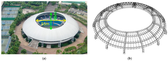
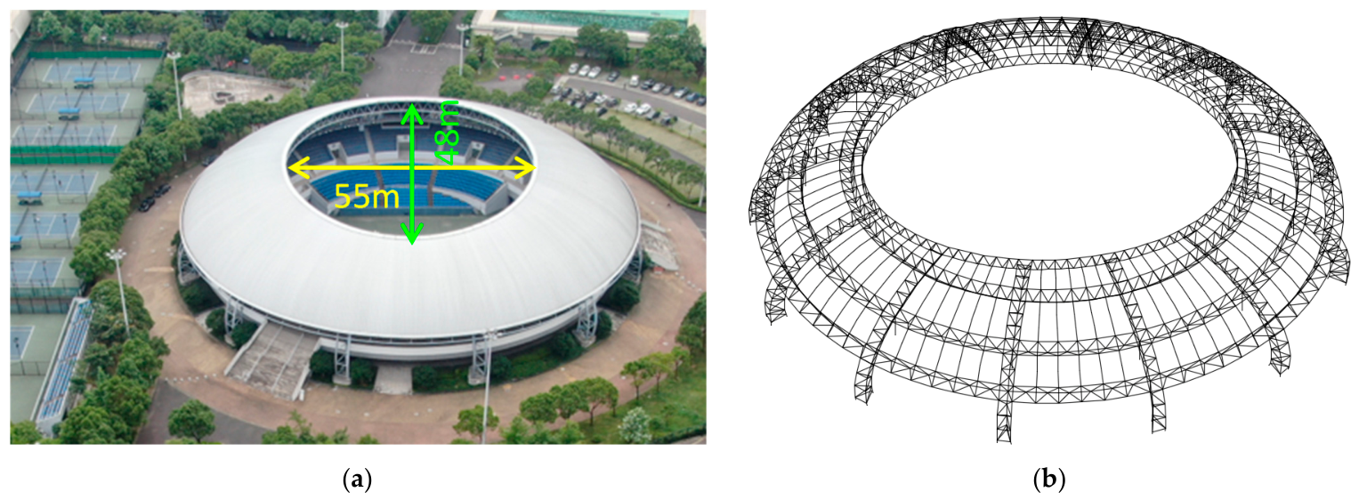
The existing stadium roof is circular in plan, with an outer diameter of 86.4 m and a height of 19.41 m. The central opening is elliptical, featuring a minor axis radius of 24.0 m and a major axis radius of 27.8 m. Twelve radial triangular tubular trusses, spaced at 30° intervals about the central axis, form the primary support system. The bottom chords of these trusses rest on concrete pedestals, while the lower chords are supported at an elevation of 11.9 m by reinforced concrete columns extending from the concrete stands. The overall spatial grid structure is completed through three concentric circular tubular trusses and one perimeter closure truss. The existing steel roof structure is illustrated in Figure 1.
Figure 1.
The existing stadium: (a) The existing stadium roof (b) Open configuration.
The existing as-built stadium was designed and built on 2007. Based on the building quality inspection report and the structural seismic appraisal report, after 18 years of service (2007–2025), the as-built stadium exhibits critical deficiencies that fail to comply with WTA 500 operational standards: outdated mechanical systems failing to meet current HVAC and acoustical standards for elite competitions. Furthermore, per the revised Code for Seismic Design of Buildings (GB 50011-2010), the seismic design parameter for the site has been upgraded from a peak ground acceleration (PGA) of 0.05 g to 0.10 g; the as-built structural system fails to comply with both the additional dead load imposed by the retractable roof system and the enhanced seismic demand under the updated design spectrum.
2.3. Renovation Scheme
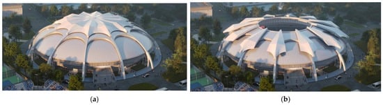
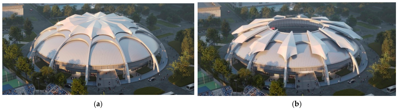
Drawing inspiration from the Camellia, the city flower of Ningbo, this renovation scheme maximizes the potential of existing site conditions. Guided by the principles of harmonizing with the existing structure and integrating with the surrounding context, the project proposes an adaptive renewal strategy focused on sustainable growth. Specifically, the design involves attaching twelve petal-shaped retractable roof structures to the exterior of the existing building (Figure 2a: closed configuration; Figure 2b: open configuration).
Figure 2.
Ningbo (Yinzhou) Tennis Center: (a) Closed configuration; (b) Open configuration.
This renovation solution extends laterally along the existing perimeter without disturbing the retained structure or requiring strengthening of the original envelope.
2.4. Newly Added Retractable Roof
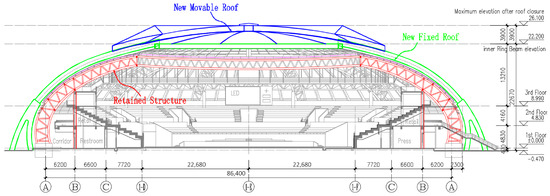
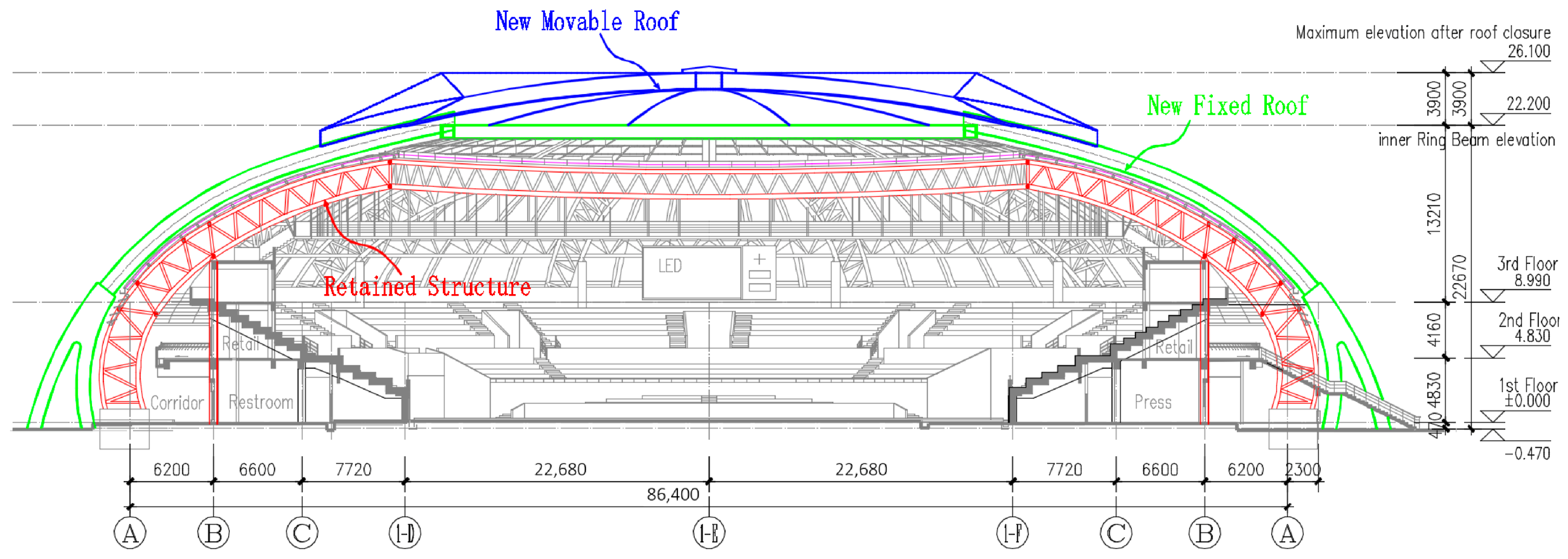
Aligned with the architectural concept, radial primary beams—serving as track girders for the movable roof—are installed externally to the 12 existing trusses of the original roof. These radial primary beams transition into lambda-shaped steel-concrete bifurcated columns beneath the eaves of the existing roof at an elevation of 10.1 m. A circular perimeter ring beam connects the 12 radial primary beams at the inner edge of the fixed roof. Edge beams are positioned within the petal-shaped cutouts at the outer perimeter of the fixed roof. Secondary radial and circumferential beams are incorporated within the structural bays defined by the radial primary beams, inner ring beam, and edge beams, forming a centrally symmetric single-layer spatial grid system. As depicted in Figure 3: Red elements denote the retained structural components; Blue elements represent the new movable roof system; Green elements indicate the new fixed roof structure.
Figure 3.
Section view of newly added and existing retained structures.
The newly added fixed roof has an outer diameter of 100.5 m and a height of 23.2 m, with a circular central opening of 38.0 m diameter. The top of the lambda-shaped steel–concrete bifurcated columns is positioned 10.1 m above ground level. The column bifurcation spans 3.8 m at the base, with the inner column leg extending horizontally 27.4 m from the radial primary beam’s inner termination point.
The newly added structure is structurally separated from the retained structure via expansion joints. The joint gap width measures 253 mm at the eaves of the existing roof and increases to 757 mm at its highest point, ensuring complete structural independence between the new and existing structure systems.
Twelve movable roof units, each comprising a spatial tubular truss assembly, connect to the fixed roof via load-bearing and drive wheels. The maximum architectural height reaches 26.3 m when the movable roof units are fully closed.
3. Retractable Roof Design
Each movable roof unit operates independently. The fully open configuration yields a central opening diameter of 38.0 m with an area of 1134 m2.
3.1. Moving Pattern
The roof employs a synchronized radial deployment mechanism where all 12 movable units traverse along the radial primary beams. These beams serve dual functions as structural supports and track girders for the movable units. The travel distance per unit is approximately 17.5 m.
As illustrated in Figure 4:
Figure 4.
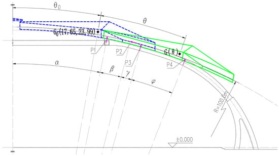
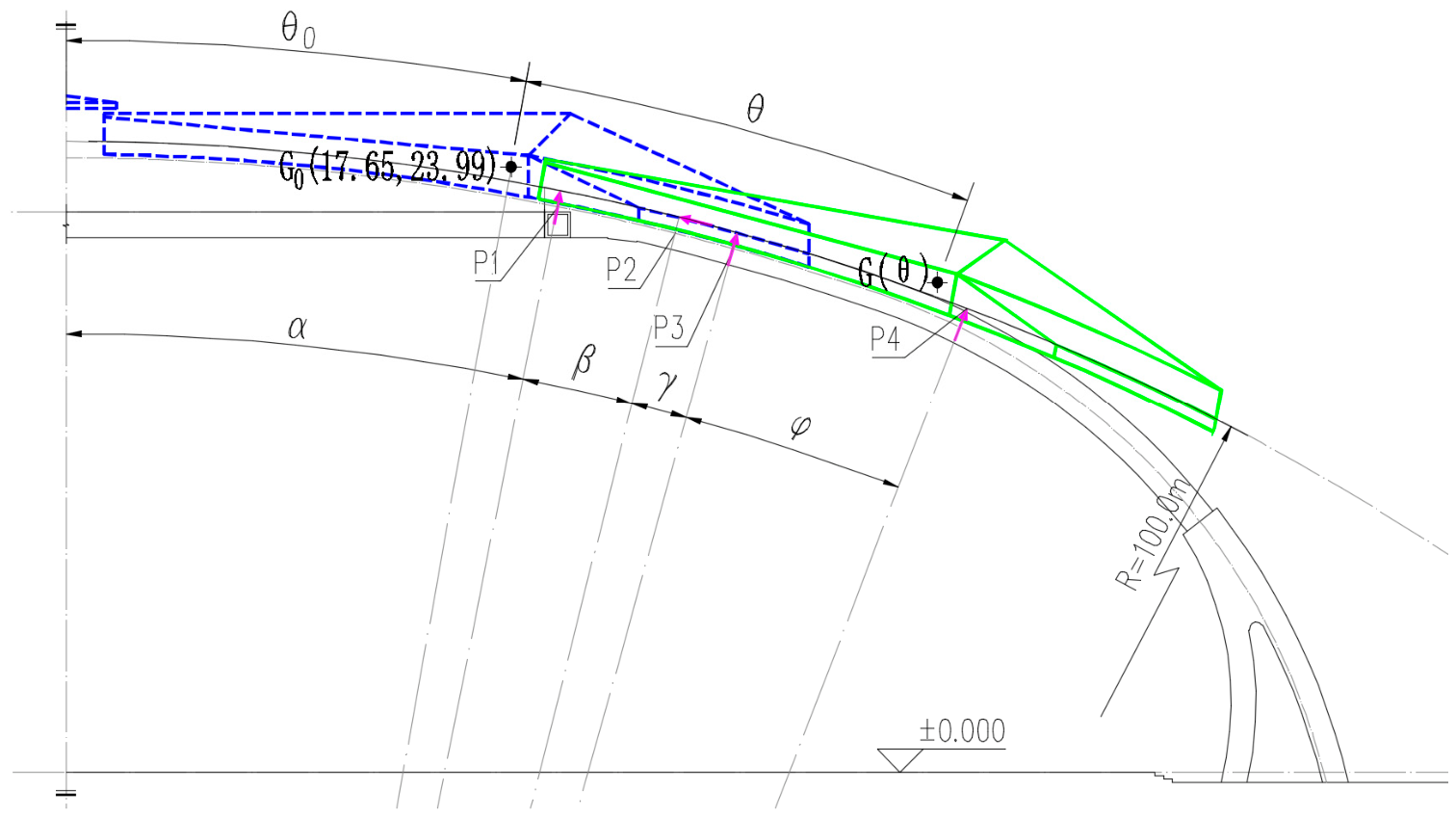
Section of newly added retractable roof under Closed and Open states (Blue dashed lines: Closed configuration; Green solid lines: Open configuration; P1~P4: connection point).
From a geometric perspective, the ideal motion trajectory of a retractable roof should be a continuous spherical surface; however, constrained by architectural design considerations and site conditions, the new structure must be positioned adjacent to the existing structure. To ensure the reliable opening and closing performance of the retractable roof, the centerline of the radial primary beam is optimized to comprise two smoothly connected tangent circular arcs. To minimize the driving force requirement and optimize the drive system cost, the front section of the radial primary beam (track beam) employs the largest feasible radius of curvature; in conjunction with architectural requirements, after parametric simulation and comparative analysis, the arc radius is determined to be 100.0 m. The starting angle of the front section centerline relative to the field center vertical axis is 11.34°, with an ending angle of 19°; the rear section centerline has an arc radius of 28.0 m and a central angle of 32.96°.
3.2. Drive System
Common drive mechanisms for retractable roofs include wheel-driven, wire rope, rack-and-pinion, chain–sprocket, and hydraulic systems [2]. Comparative analysis of force transmission capacity, applicable slope/span limits, precision, and cost is provided in Table 1.
Table 1.
Comparison of Drive Methods.
From an engineering perspective, given the compact spatial constraints, moderate unit weight (469.7 kN per unit), significant track slope, high unit quantity, and stringent synchronization requirements, a rack-and-pinion drive system was selected.
In the open and closed configurations, the overlap dimension of the architectural finished surface is approximately 10.9 m; after deducting the exterior cladding, the structural overlap dimension is approximately 9.0 m. After reserving 900 mm installation clearance at both ends, within the 7.2 m overlap segment, two load-bearing connection points (Connection Points 1 and 3 in Figure 4) and one drive connection point (Connection Point 2 in Figure 4) are arranged. According to architectural aesthetic requirements, an additional load-bearing connection point (Connection Point 4 in Figure 4) is positioned at the outermost location.
During the opening process, when the retractable roof reaches a specific travel distance, the innermost Connection Point 1 disengages from the track, and Connection Point 4 engages. At any position throughout the opening and closing travel, the retractable roof transmits force to the fixed roof via two load-bearing connection points (Connection Points 2 and 4) and one drive connection point (Connection Point 2). The linear operating speed of the retractable roof is 3 m/min, completing one opening or closing cycle in approximately 6 min.
3.3. Floating Engagement Mechanism
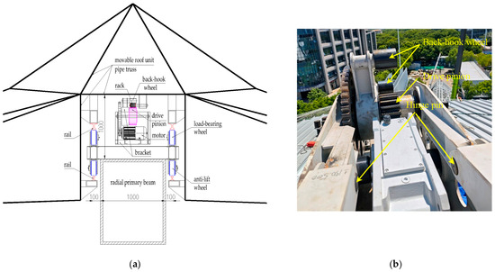
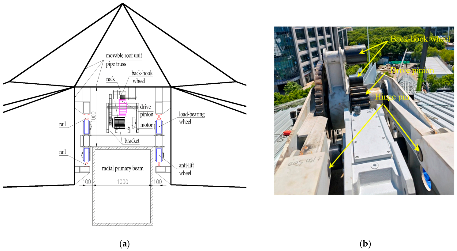
The horizontal travel distance of each movable roof unit is 19.0 m, which is less than the dimension of the retractable roof unit in the opening/closing direction (28.2 m). The power unit is mounted on the radial primary beam of the fixed roof, with the rack fixed to the retractable roof. On each retractable roof unit, two tracks are positioned at web locations corresponding to the width range of the fixed roof’s radial primary beam; each track transmits normal forces to the fixed roof through two sets of load-bearing wheels mounted at fixed positions on the upper surface of the radial primary beam and oppositely configured anti-lift wheel groups. A centrally aligned rack is installed on each retractable roof unit, with the drive pinion and motor mounted on a bracket. One end of the bracket connects via a hinge pin to a support fixed on the radial primary beam surface, while the other end engages with the back of the rack through a back-hook wheel positioned opposite the top of the drive pinion, forming a floating engagement mechanism (Figure 5). Powered by drive motors, this integrated mechanical system enables synchronized opening and closing operations of all movable units with continuous wheel–rail engagement, ensuring smooth transition through critical kinematic phases without impact loading or track disengagement.
Figure 5.
Drive and rail system layout. (a) Schematic section showing the wheel–rail arrangement and drive mechanism; (b) On-site construction photos of floating engagement mechanism: back-hook wheel and hinge pin.
3.4. Kinematic Parameters and Reaction Calculation for Wheel and Rail Design
Due to the compact installation space for the wheel set and rail system, which is only 1.2 m wide and 1.0 m high as shown in Figure 5, it is necessary to calculate the reaction forces of the wheel–rail system and provide them to the specialized units responsible for mechanical design and drive control. This ensures that the reserved confined space meets the dimensional requirements of the wheel sets and rails, as well as the needs for installation and commissioning, thereby ensuring the feasibility and constructability of the solution.
As shown in Figure 4, each movable roof unit can be regarded as a rigid body with a concentrated unit weight G (469.67 kN), moving along an arc around the center point O. Coordinates of rotation center i.e., m.
The fully closed condition is assumed as the initial state, and the coordinates of the r mass center in this state are defined as (): m
As the movable roof rotates θ around the center point from the closed configuration to the open state, the coordinates of its mass center can be calculated as follows:
where θ is the rotation angle along clockwise;
Let , denote the reaction forces at connection Points 1, 2, 3, and 4, respectively, where the coordinates of connection point i are defined by:
where:
: Angular position of point i (i = 1, 2, 3, 4) relative to rotation center O (rad)
R: Radial distance from rotation center O to the connection point trajectory 100.0 m
For equilibrium, the sum of moments about rotation center O (track arc center) must satisfy:
Therefore the tangential drive force at connection Point 2 is derived as:
Then taking moments about connection Point 3 yields:
Therefore,
Substituting Equation (4) into Equation (5), The reaction force at connection Point 1 is derived as:
Similarly, taking moments about connection Point 1:
The reaction force at connection Point 3 is derived as:
Following disengagement from connection Point 1, the movable roof transfers loads to the fixed structure through Points 2, 3, and 4. For the concurrent force system acting on the movable unit, taking moments about Point 4 yields the equilibrium condition:
After disengagement of connection point 1 and engagement of connection point 4, the reaction force at connection Point 3 is derived as:
Similarly, taking moments about connection Point 3:
The reaction force at connection Point 4 is derived as:
The travel distance L can also be calculated as:
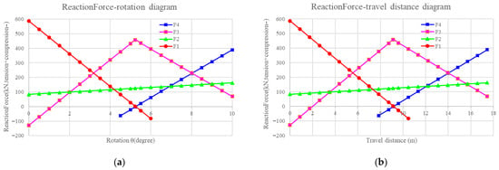
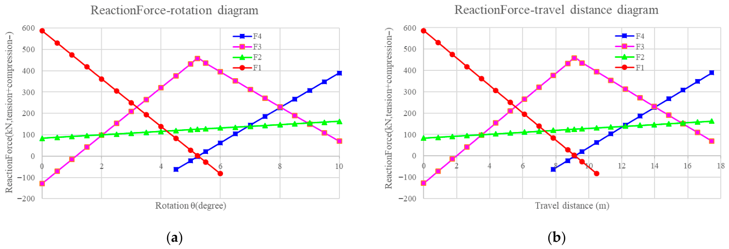
Thus, the reaction force V.S. rotation or travel distance can be drawn in Figure 6 as below:
Figure 6.
Reaction Force diagram. (a) Reaction Force vs. rotation; (b) Reaction Force vs. rotation/travel distance.
As shown in Figure 6, under the self-weight of a single retractable roof unit, in the Open configuration both load-bearing connection points are under compression, while in the closed configuration Connection Point 1 is under compression and Connection Point 3 is under tension. During the transition from open to closed configuration, the driving force decreases from 118.1 kN to 77.9 kN.
This equilibrium equation governs the load redistribution during transition, ensuring continuous wheel–track engagement without impact loading. The solution satisfies:
for θ > 5.264°, indicating stable load transfer to Point 4 after disengagement from Point 1.
The connection point internal forces calculated above can be provided to the specialized mechanical firm as the basis for drive and track systems design. In this engineering practice, the mechanical and electrical control of the drive and rail system was designed and installed by Zhejiang Dafeng Industrial Co., Ltd., Hangzhou, China.
4. Structural System and Component-Based Static Analysis
4.1. Design Parameters
The project is designed for seismic fortification intensity 7 (0.10 g peak ground acceleration) with the first group of seismic design parameters on Site Class III (equivalent to ASCE 7-22 Site Class D), featuring a characteristic structural period of 0.45 s. The structure is classified as Seismic Fortification Category C per GB 50223-2008 with Structural Safety Level II, corresponding to ASCE 7-22 Occupancy Category III and Seismic Design Category B.
The mode–superposition response spectrum method was adopted for seismic analysis. The maximum seismic influence coefficient for the fortification level was taken as 0.08, with a characteristic period of 0.45 s.
The basic wind pressure in Yinzhou District, Ningbo, is taken as 0.5 kN/m2 (with a return period of 50 years) and 0.60 kN/m2 (with a return period of 100 years). The monthly average maximum temperature for a 50-year return period is 37 °C, and the minimum is −3 °C. The steel structure closure temperature ranges from 7 °C to 27 °C. For the overall temperature action on the roof steel structure, the maximum temperature rise in the outdoor area is +30 °C, and the maximum temperature drop is −30 °C, determined based on the differences between the extreme temperatures and the initial closure temperature limits.
Structural members are made of Q355 steel with an elastic modulus of 206,000 MPa. All members are simulated using beam elements. Column bases are defined as fully fixed supports. The connection between the fixed roof and movable roof is simplified using T-shaped and short axial struts simulating load-bearing wheels and driving motor. Uniform and complete load combinations are applied throughout all analytical models.
Structural analyses were performed using commercial finite element software. Static, modal, and response spectrum analyses were carried out using Midas Gen 2024v2.1. Elastoplastic time-history analysis and stability analyses, including linear buckling analysis and geometric nonlinear analysis considering initial imperfections, were performed using SAP2000 V25. Both models share identical geometry, section properties, material properties, boundary conditions, and load cases. Cross-validation of linear static results between the two software packages showed differences of less than 5%, confirming model consistency.
To evaluate the seismic performance under major earthquakes (PGA = 220 cm/s2, corresponding to a 2% probability of exceedance in 50 years), nonlinear time history analyses were performed using Midas Gen. The following parameters and procedures were adopted: Ground motion selection: Three natural records—Imperial Valley wave (1940, El Centro), Chi-Chi wave (1999, TCU068), and an artificial wave (Lanzhou artificial wave) generated to match the target response spectrum for Site Class III—were selected as input motions. All records were scaled to the target PGA of 220 cm/s2 and applied simultaneously in three orthogonal directions (X:Y:Z = 1:0.85:0.65).
Integration method: Newmark’s constant average acceleration method was employed with a fixed time step of 0.02 s.
Damping model: Rayleigh damping was assumed with a damping ratio of 2% for the first two natural frequencies of the structure.
Material nonlinearity: Q355 steel was modeled using a bilinear kinematic hardening model with an elastic modulus of 206,000 MPa, yield strength of 345 MPa, and a tangent modulus of 4120 MPa (2% of the elastic modulus) after yielding.
Geometric nonlinearity: Large displacement effects were considered using the updated Lagrangian formulation.
Convergence criteria: The analysis was considered converged when the relative displacement tolerance was less than 1 × 10⁻⁴ and the force tolerance was less than 1 × 10⁻³.
The time history analysis results were used to assess the seismic gap safety as presented in Section 7.
4.2. Structural Configuration
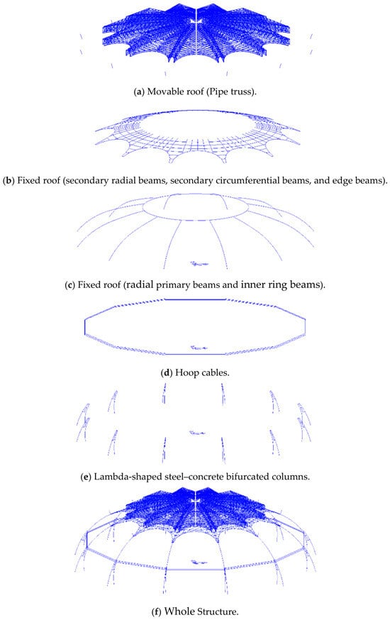
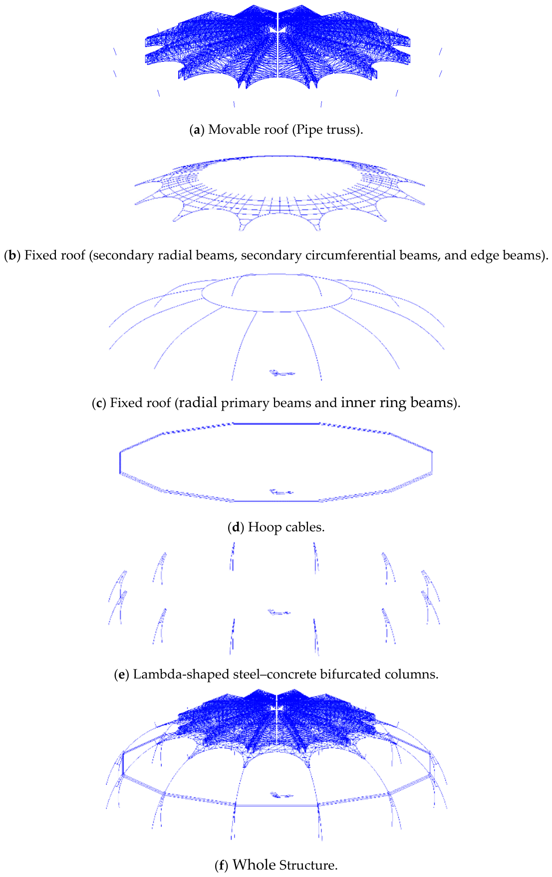
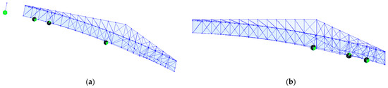
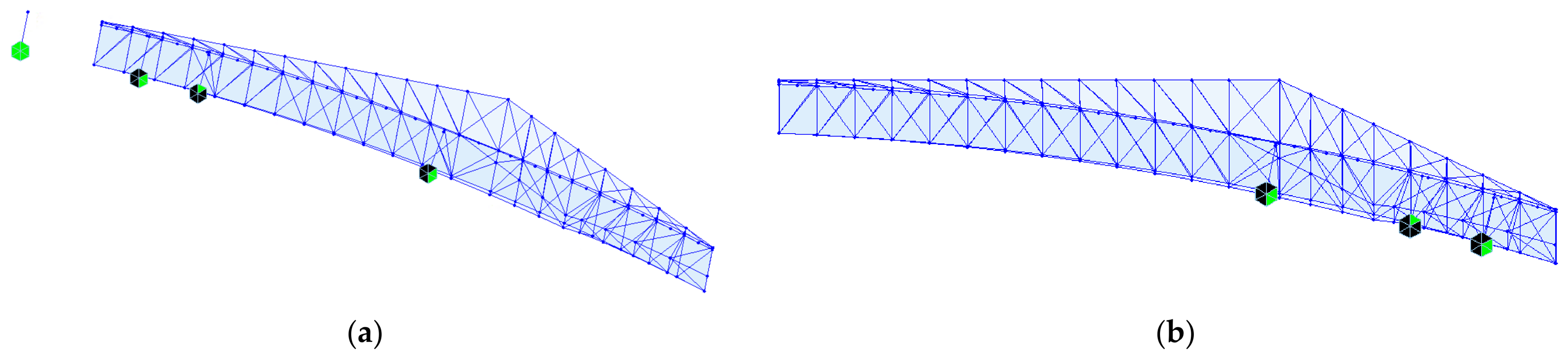
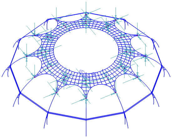
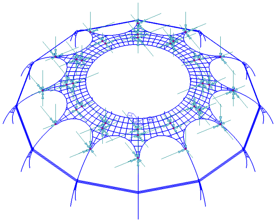
The structure incorporates no basement, utilizing cast-in-place concrete pedestals interconnected by tie beams as foundations, with the structural fixity assumed at the foundation top elevation. The movable roof (Figure 7a) employs a spatial tubular truss system, while the fixed roof integrates three subsystems: (1) the primary structural grid comprising radial primary beams, inner ring beams (Figure 7c), secondary radial beams, secondary circumferential beams, and edge beams (Figure 7b); (2) a hoop cable system (Figure 7d); and (3) lambda-shaped steel–concrete bifurcated columns (Figure 7e), collectively forming a single-layer spatial grid structure.
Figure 7.
Overall Structural Configuration.
4.3. Connection Interface Between Movable and Fixed Roofs
The retractable roof and fixed roof are interconnected through the drive and track system, with each retractable roof unit transferring forces to the fixed roof via two load-bearing connection points and one drive connection point.
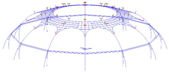
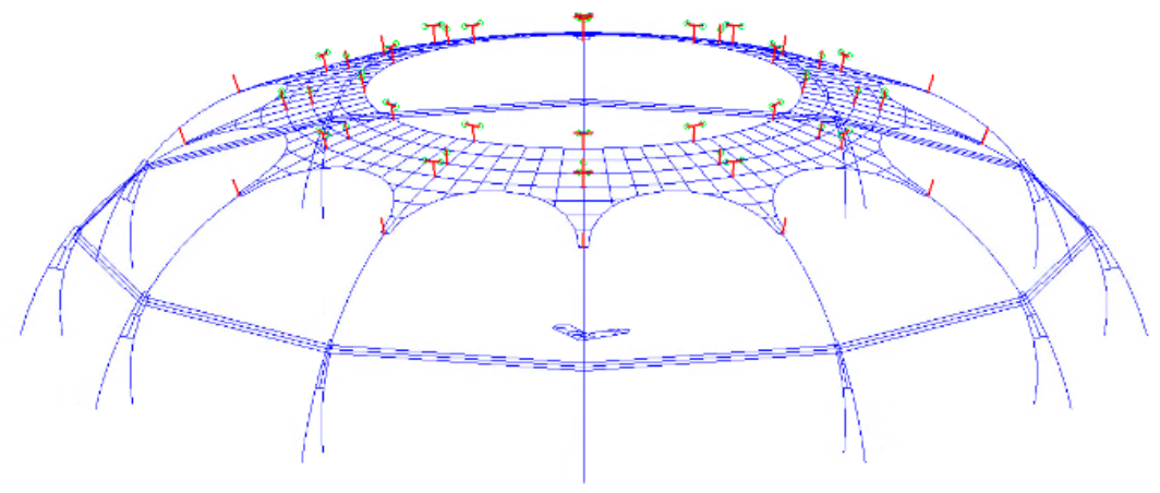
At each load-bearing connection point, normal compressive forces are transmitted through a pair of load-bearing wheels, while normal tensile forces are conveyed via a corresponding pair of anti-lift wheels. These wheels are arranged symmetrically in left and right pairs along the radial primary beams, positioned at the same elevation with a horizontal spacing of 1.2 m. For computational modeling of the connection interface, a T-shaped component oriented normal to the radial primary beam is introduced. This component connects the retractable roof to the corresponding nodes of the radial primary beam. At its end adjacent to the retractable roof, the T-shaped component is modeled with releases tangential translational freedom (Ux) and rotational freedom about the local axial axis (Rz), retaining only the normal translational degree of freedom, as illustrated in Figure 8.
Figure 8.
Connection Interface modeling and load-bearing connection details.
Each movable roof unit transfers loads to the fixed roof through two load-bearing connection points and one drive connection point via the track and drive mechanism. At each load-bearing connection, normal compressive forces are transmitted through dual symmetrically arranged load-bearing wheels along the radial primary beam, while normal tensile forces are conveyed via dual symmetrically positioned up-stop wheels. In computational modeling, these connections are represented by T-shaped connectors linking corresponding nodes of the movable roof and radial primary beams, with tangential translational freedom (Ux) and rotational freedom about the vertical axis (Rz) released at the movable roof interface as illustrated in Figure 9 (integrated 3D model of fixed roof and connections) and Figure 10 (load-bearing connection details).
Figure 9.
Sub-assembly model of a single movable unit: (a) Closed configuration; (b) Open configuration.
Figure 10.
Sub-assembly model for the fixed roof.
At the drive connection point, tangential driving force is transmitted through the drive pinion on the drive motor to enable the opening and closing movement of the retractable roof. This connection is modeled as a short axial strut oriented normal to the radial main beam connecting corresponding nodes; the upper end of the short axial strut releases axial translational (Uz) and rotational freedom (Rx), constraining only the tangential translational degree of freedom.
4.4. Component-Based Static Analysis
The fully open configuration constitutes the baseline operational state, with structural design conducted through envelope analysis considering both open and closed configurations. The static analysis proceeds through a sequential two-stage procedure: first, component-based static analysis of the isolated movable roof units determines support reactions; subsequently, these resultant reactions are applied to corresponding locations on the fixed roof structure for component-based static analysis of the fixed roof system. This methodology ensures accurate load path representation during transition phases while maintaining computational efficiency for the complex retractable system.
As can be seen from Table 2, the self-vibration characteristics and self-vibration modes of the movable roof sub-assembly model are presented. It can be observed that the stiffness of the model in the closed configuration is greater than that in the Open configuration, and the natural vibration periods and modes under both states are relatively close. The first vibration mode is the vertical antisymmetric vibration of the left and right wings, followed by lateral translation and torsion about the longitudinal axis, and finally the overall vertical vibration of the cantilevered section.
Table 2.
Natural vibration characteristics of the closed-state movable roof sub-assembly model.
As shown in Table 3, under the dead load condition, the movable roof sub-assembly model exhibits compressive forces at both load-bearing connection points in the Open configuration; in the closed configuration, connection point 1 is compressive while connection point 3 is tensile. The actuation force decreases from 118.1 kN to 77.9 kN as the movable roof transitions from the open to the closed configuration. The support reactions of the movable roof sub-assembly model can serve as the design basis for the rail system.
Table 3.
Support reactions of the movable roof sub-assembly model under static load cases (kN).
The support reactions of the movable roof under various static load conditions are applied to the corresponding positions of the fixed roof, and the static analysis of the fixed roof sub-assembly model (Figure 10) is conducted.
The natural vibration modes of the fixed roof subassembly model are presented in Table 4. It can be observed that the fixed roof is a single-layer dome-shaped spatial grid structure. Due to the different positions of the movable roof and the corresponding reaction forces on the fixed roof between the closed and open configurations, there is a significant difference in mass distribution. The natural period in the closed configuration is notably longer than that in the Open configuration. However, the overall modal shapes in both open and closed configurations are relatively similar, with the first two modes being vertical antisymmetric vibrations in both cases.
Table 4.
Natural vibration characteristics of the open-state fixed roof sub-assembly model.
Considering static load cases including dead load (D), live load (L), and temperature action (T+), a static analysis of the fixed roof was conducted. The vertical deformations and support reactions under these static load cases are summarized in Table 5 and Table 6, respectively. As indicated in Table 5, under dead load, the maximum vertical deformation in both open and closed configurations occurs at the inner ring beam, with the deformation in the closed configuration being approximately 3.7 times that in the Open configuration. Under live load, the maximum vertical displacement of the subassembly model in the Open configuration occurs at connection point 4, where the inner ring beam bulges upward by 1.44 mm. Vertical deformation is governed by dead load, with live load-induced deformation accounting for about 15% of that under dead load. Since the fixed roof subassembly model is a geometrically stable system with redundant constraints, significant internal forces develop in the steel structure under temperature action, resulting in deformations larger than those under live load. Thus, temperature action is the controlling variable load.
Table 5.
Vertical deformation of the fixed roof sub-assembly model under static load cases.
Table 6.
Support reactions of the fixed roof sub-assembly model under static load cases.
Table 6 shows that, unlike continuous cantilever structures, the fixed roof is a single-layer spatial grid structure. The radial main beams, constrained by the inner ring beam, bulge outward under dead load. Consequently, the inner leg of the λ-shaped bifurcated column connected to these beams is subjected to tension, which increases from 485 kN to 3223.7 kN during the closing process. The outer leg is under compression and experiences substantial horizontal force, which increases from 1304 kN to 2289 kN during closing.
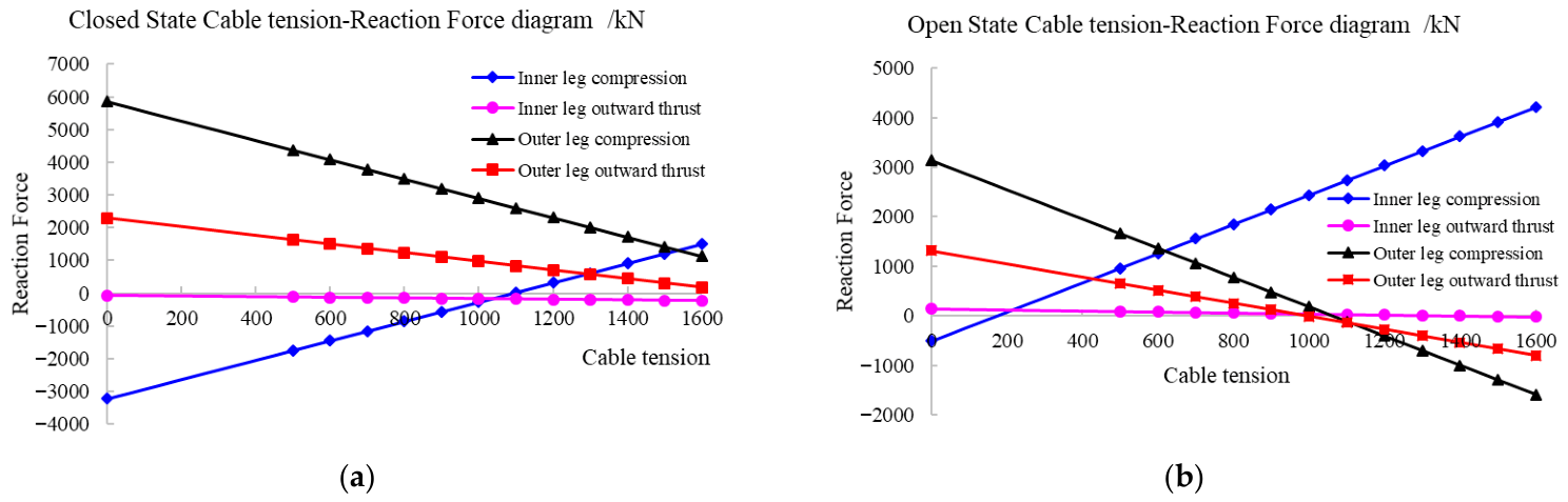
To effectively reduce the tensile force at the column base and the horizontal thrust, thereby lowering the design difficulty and cost of the foundation, circumferential hoop cables were installed at the top of the λ-shaped bifurcated composite columns to restrain the outward bulging deformation. Considering the multi-state operation characteristics of the retractable roof, the cable force must not be excessive, which could otherwise cause the horizontal thrust in the Open configuration to reverse inward. Taking architectural visual effects into account, three rings of cables were arranged along the top of the λ-shaped bifurcated composite columns.
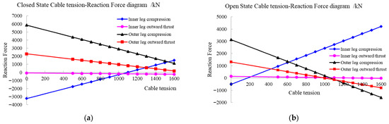
The relationship between cable force and column base reactions is illustrated in Figure 11. As shown, when the cable force increases from 0 to 1050 kN, the tensile force in the inner leg, the compressive force in the outer leg, and the horizontal thrust in both legs all decrease. Specifically, in the closed configuration, the tensile force in the inner leg decreases from 3134 kN to nearly zero, and the horizontal outward thrust in the outer leg decreases from 1315 kN to 905 kN. In the Open configuration, the tensile force in the inner leg decreases from 507 kN to zero and then transitions to a compressive force of 2590 kN, while the horizontal outward thrust in the outer leg decreases from 1315 kN to nearly zero.
Figure 11.
Cable tension–Reaction Force diagram: (a) Closed configuration; (b) open configuration.
It should also be noted that the horizontal outward thrust in the outer leg here is 1315 kN, which is slightly larger than the value of 1304.2 kN listed in Table 6. This indicates that the integrated assembly model can better reflect the inherent stiffness of the movable roof and the interaction between the movable roof and the fixed roof. Therefore, the realistic results obtained from the integrated assembly model should be adopted for envelope design in practical engineering.
Therefore, the cable force is taken as 1050 kN, ensuring no uplift force at the column base under both limit states while significantly reducing horizontal forces. By installing the cables, the uplift force in the inner leg and the horizontal force in the outer leg under dead load in the open configuration are balanced, effectively reducing the forces transmitted to the foundation. Additionally, the stress stiffening effect provided by the cables enhances the stability of the radial main beams.
5. Static Analysis of the Integrated Assembly Model
5.1. Natural Vibration Characteristics
The natural vibration characteristics and modes of the integrated model in the closed configuration are shown in Table 7. It is evident that the subassembly model, which applies the movable roof as loads onto the fixed roof, offers clear conceptual understanding and can reveal the natural vibration characteristics and mechanical behavior of both the fixed and movable roofs individually. However, compared to the integrated model, the subassembly model neglects the inherent vibration of the movable roof and its coupling effects with the fixed roof.
Table 7.
Natural vibration characteristics of the integrated assembly model.
The natural vibration modes of the integrated model and the fixed roof subassembly model are similar in form, with close periods and slightly lower stiffness in the integrated model. The integrated model can reveal the most vulnerable locations of the overall structure, with the maximum vibration amplitudes in the first four modes all occurring at the head of the movable roof. Therefore, it is necessary to employ both the subassembly and integrated models for computational analysis and envelope design under various states.
5.2. Wind Load
The main stadium incorporates a newly added retractable roof, characterized by a complex geometry that necessitates wind tunnel testing to determine the wind load shape coefficients.
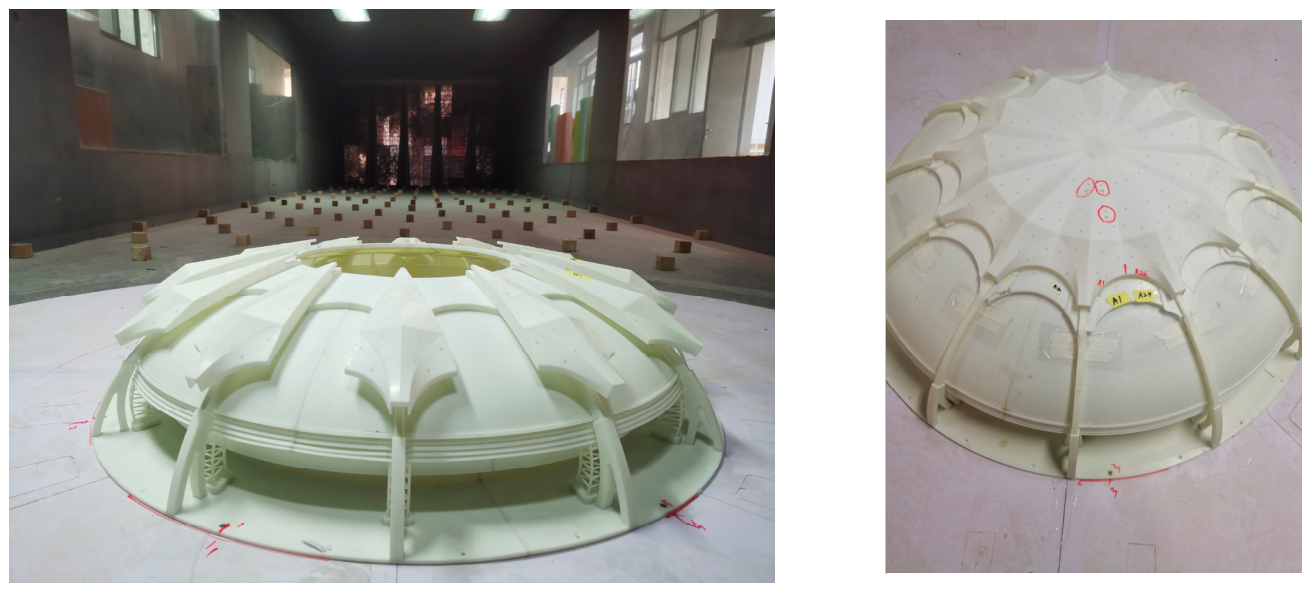
The structural model was fabricated by 3D printing using photosensitive resin with a geometric scale ratio of 1:100. A total of 432 pressure measurement points were arranged on the wind tunnel model when the main structure was in the open state, while 240 pressure measurement points were arranged when it was in the closed state. The pressure measurement pipelines were connected to an electronic scanning valve for pressure data collection. In accordance with the specification GB50009-2012, the ground roughness of the wind field was classified as Category C, which was simulated using spires and roughness elements.
The physical model used for the wind tunnel testing is shown in Figure 12 as below:
Figure 12.
Wind tunnel model.
Furthermore, CFD simulation was conducted to determine the wind vibration coefficients. In terms of the size setting of the CFD calculation domain, to ensure the reliability and accuracy of the simulation results, the standards of fluid dynamics and practical engineering experience are usually referred to. The size of the calculation domain is all referenced to the diameter D of the venue; the length, width, and height of the calculation domain are set to 19D, 23D, and 7D respectively, which have met the numerical calculation requirements for building wind load calculation. The aspect ratio of the domain conforms to the standards of conventional CFD calculations, enabling full capture of fluid flow and effectively avoiding potential boundary interference during the calculation process. Through this setting, the wind pressure distribution of the venue under different wind speeds and wind directions can be accurately simulated, thereby providing reliable data support for wind load analysis.
Due to the adoption of the unsteady Large Eddy Simulation (LES) turbulence model in the CFD calculation, the Synthetic Eddy Method (SEM) is used to generate a transient velocity inlet satisfying the Category C terrain at the inlet boundary condition of the calculation domain (where the average wind profile exponent is taken as 0.22). The numerical simulation of the flow field takes the Navier–Stokes equations (the continuity equation and momentum conservation equation for the around-flow wind) as the basic control equations, and the discretized numerical simulation method is used to solve the flow field.
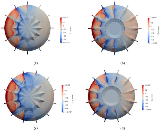
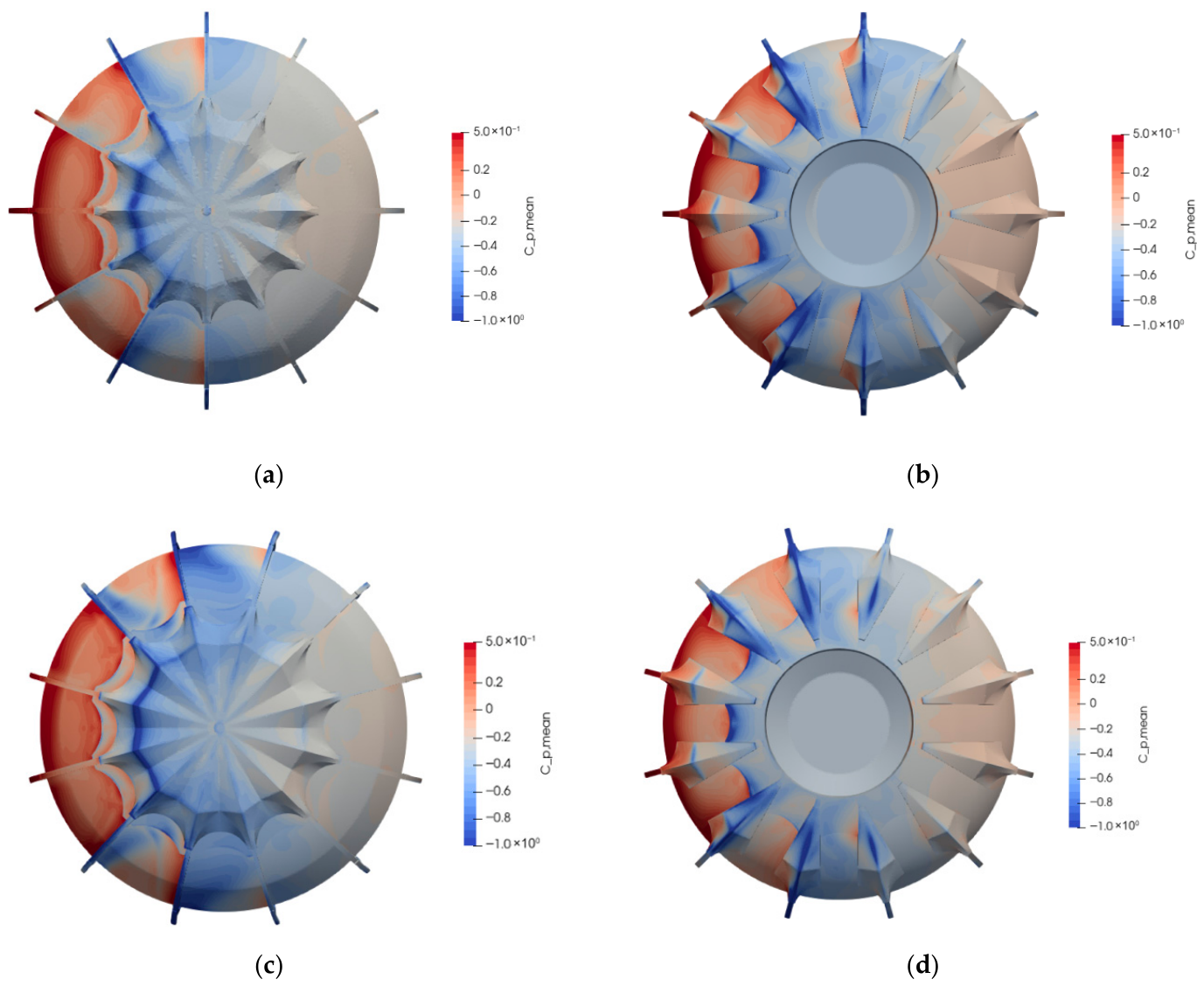
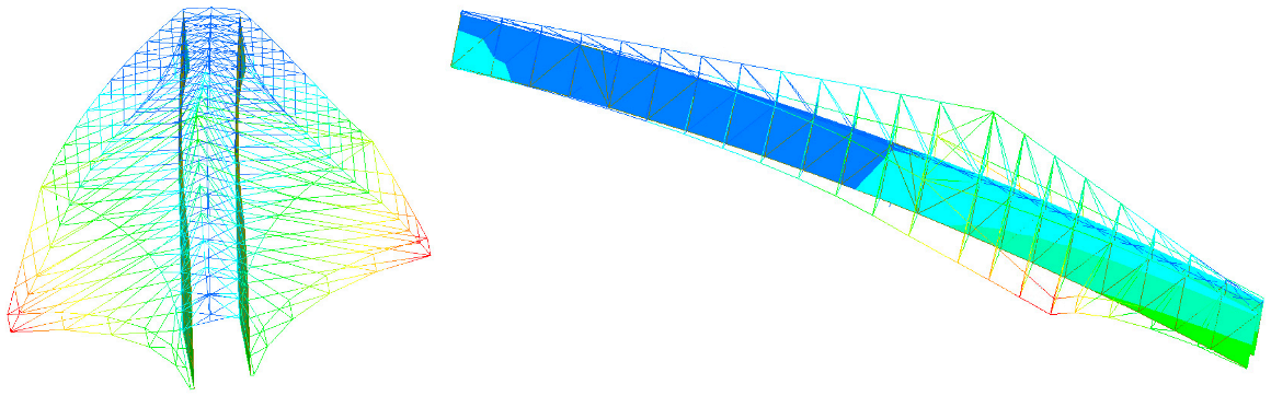
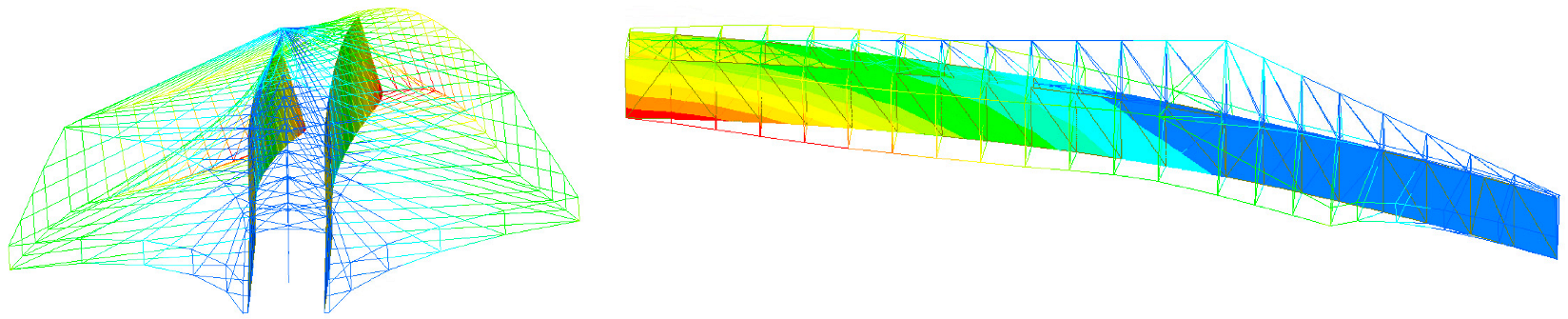
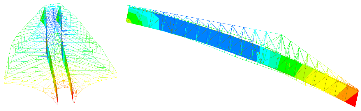
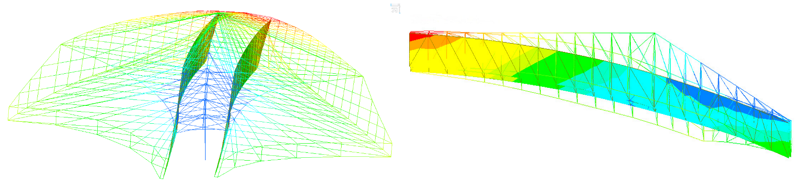
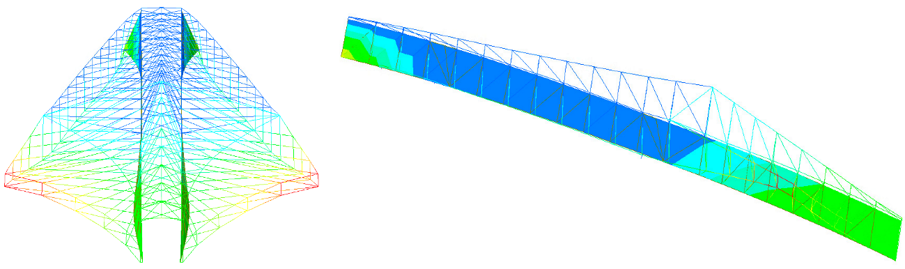
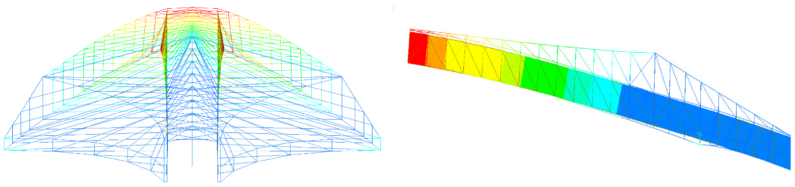
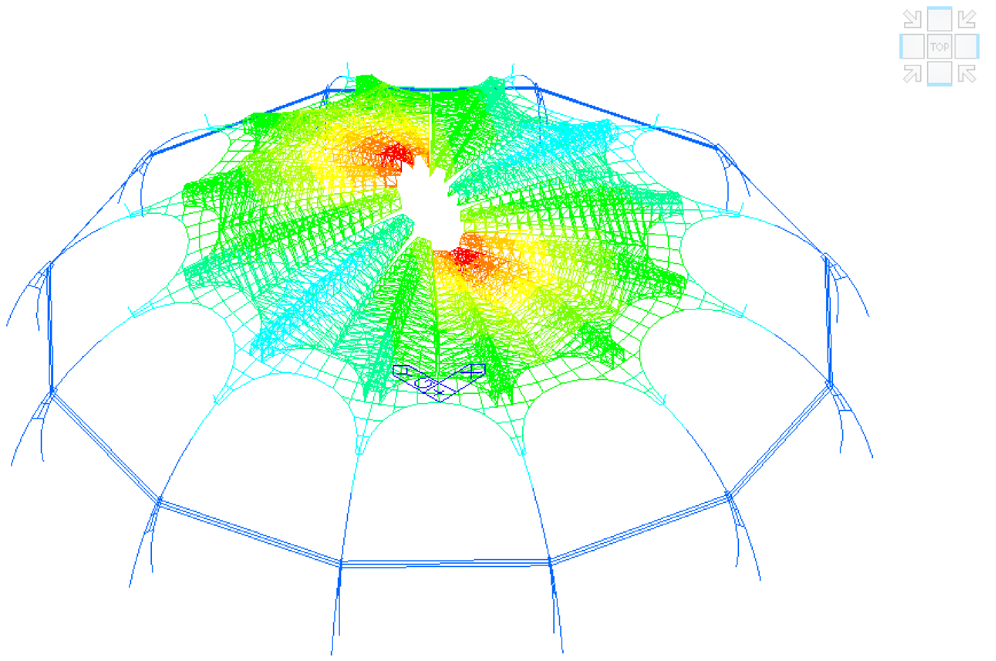
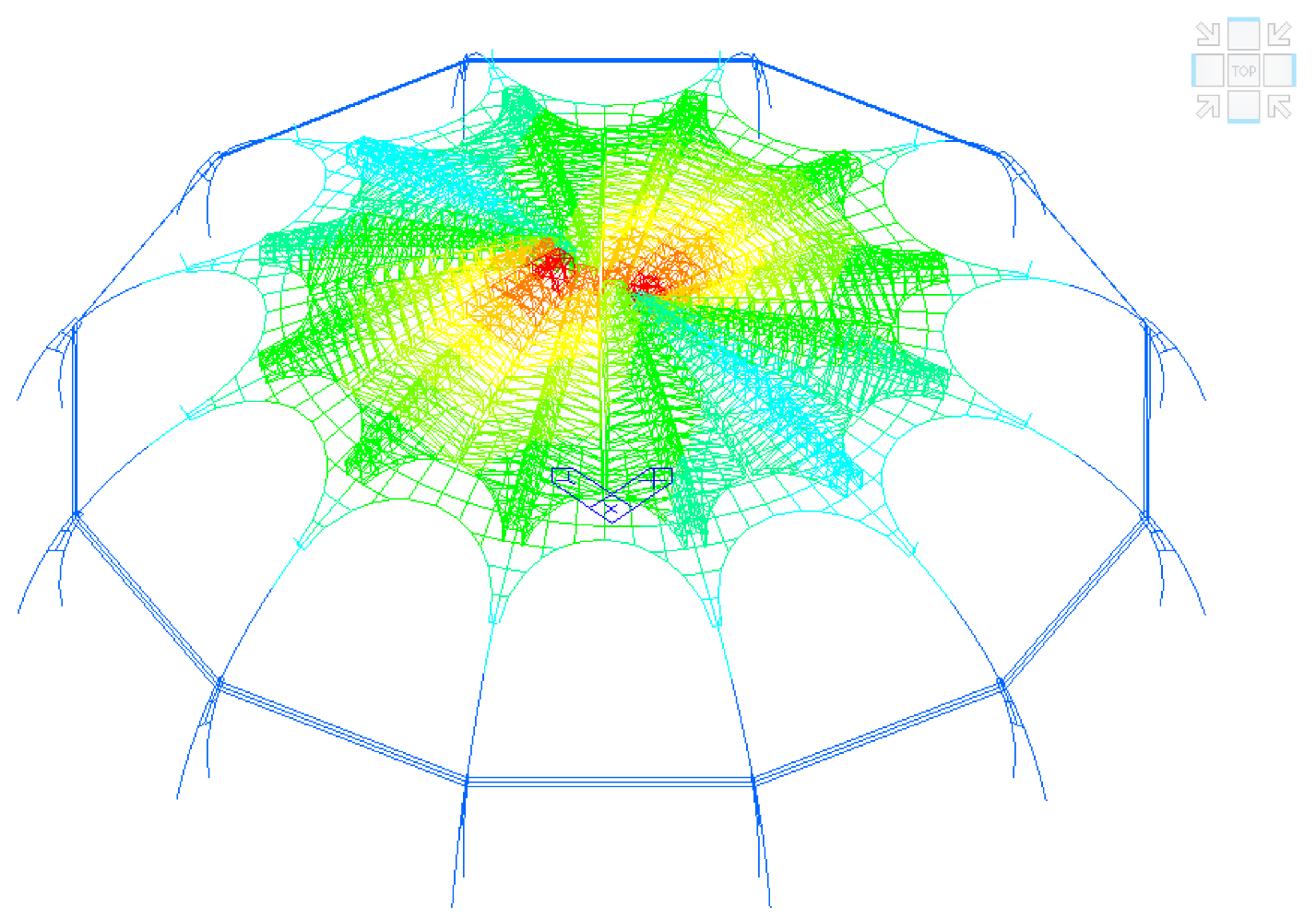
Figure 13 present contour plots of mean wind pressure coefficients for the roof under closed and open configurations at 0° and 15° wind direction angles, respectively. The wind pressure coefficients are referenced to the mean wind speed at building height. This study focuses exclusively on the newly added roof structural system. In the closed configuration, negative pressures concentrate primarily at the upwind canopy projections of the movable roof section. In the open configuration, negative pressures manifest at the annular edge details and bilateral canopy projections of the movable roof.
Figure 13.
Wind pressure coefficient distribution on the roof from numerical wind tunnel simulation: (a) 0° wind direction angle in closed configuration, (b) 0° wind direction angle in open configuration, (c) 15° wind direction angle in closed configuration, (d) 15° wind direction angle in open configuration.
Based on the mean wind pressure coefficients (Cp,mean) measured at test points across various heights (z) in this study, the corresponding shape coefficients () can be readily derived through non-dimensionalization as follows:
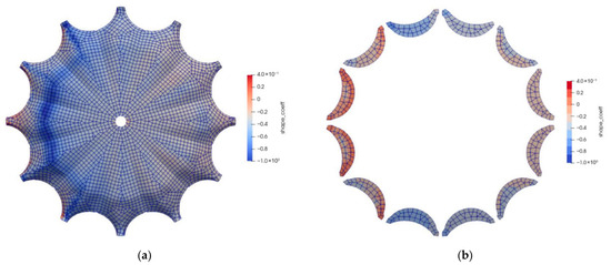
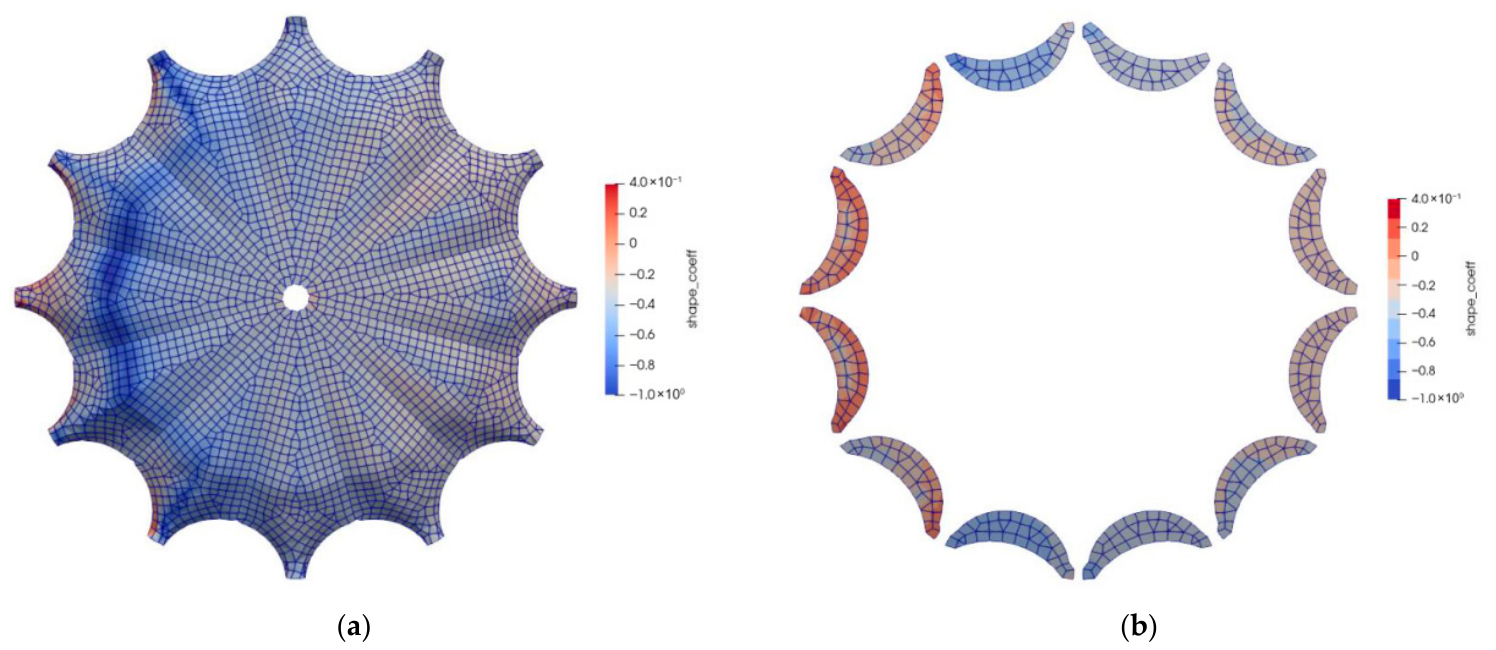
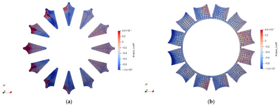
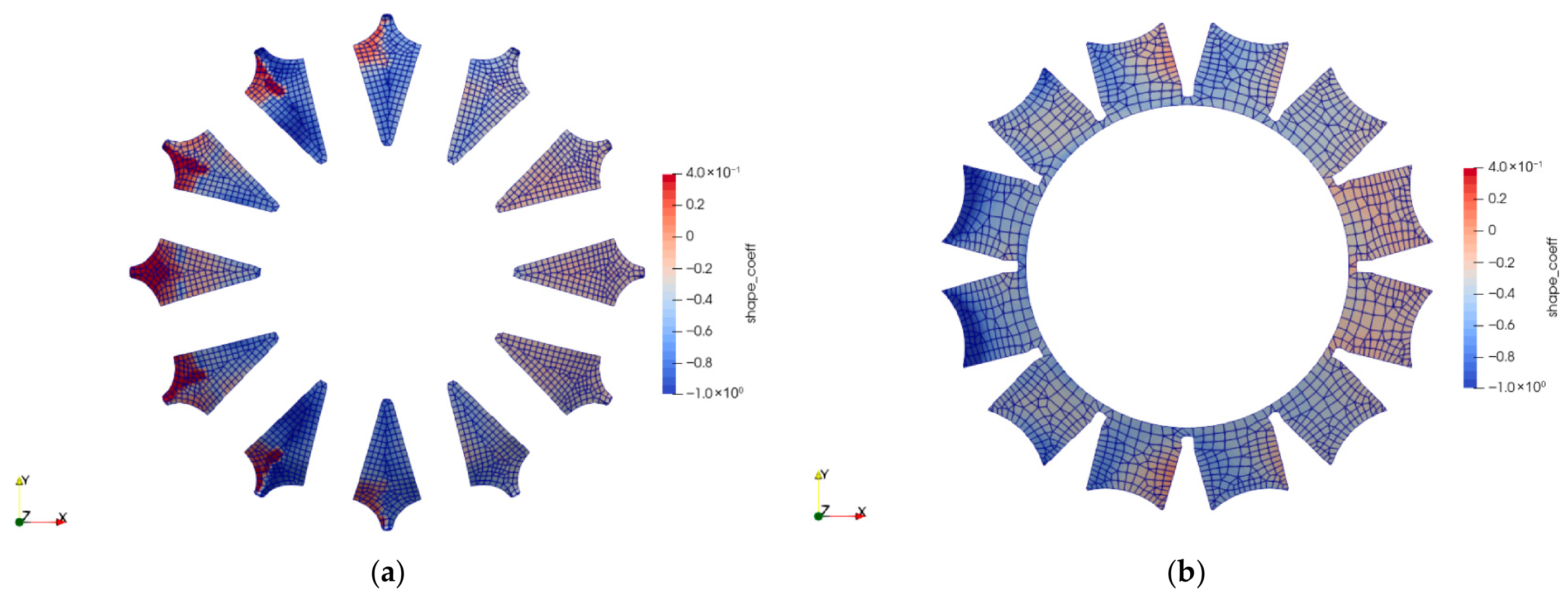
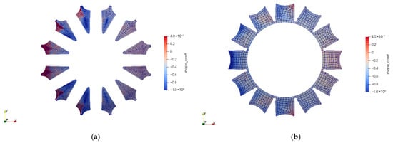
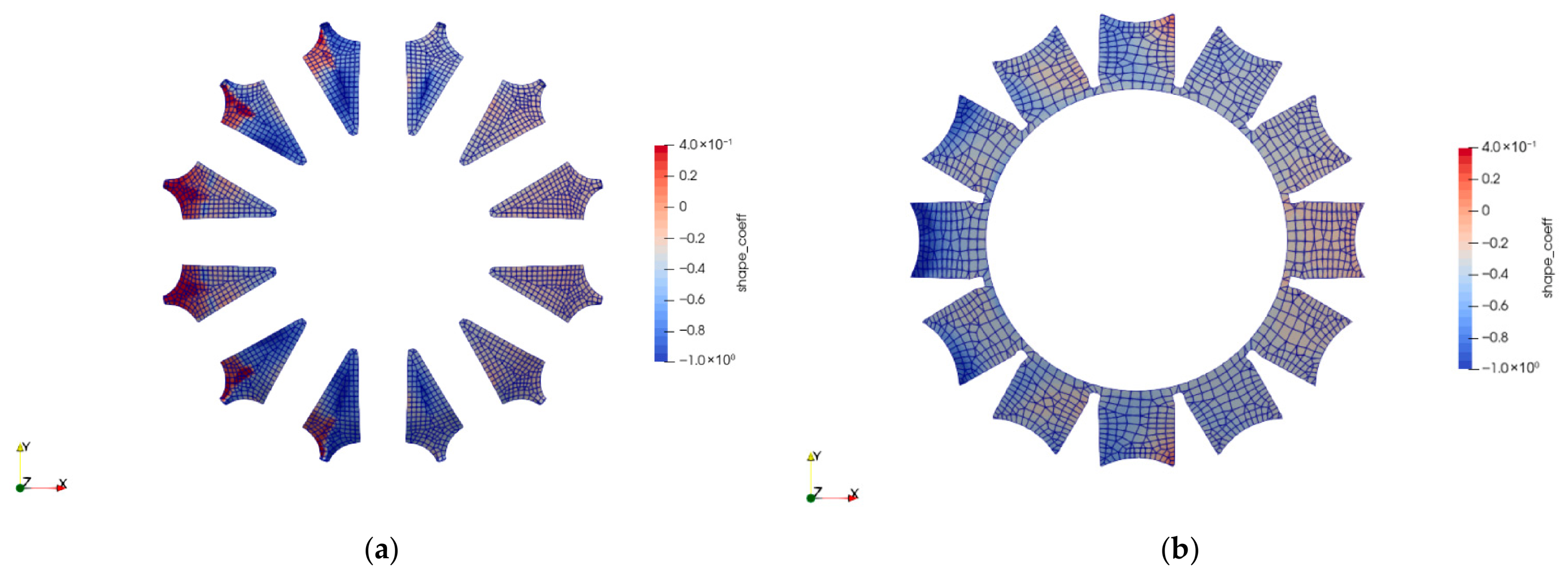
Figure 14 present shape coefficient distributions for the closed movable roof and fixed roof sections at 0° wind direction angle. The minimum shape pressure coefficient (most negative value) is −1.12 on the movable roof section and −0.66 on the fixed roof section. Figure 15 shows corresponding distributions for the open-roof configuration, where the minimum values reach −2.28 (movable roof) and −1.99 (fixed roof), representing a 104% and 200% increase in suction magnitude compared to the closed configuration, respectively.
Figure 14.
Wind shape coefficient distribution on the roof from numerical wind tunnel simulation at 0° wind direction angle in closed configuration: (a) movable roof, (b) fixed roof.
Figure 15.
Wind shape coefficient distribution on the roof from numerical wind tunnel simulation at 0° wind direction angle in Open configuration: (a) movable roof, (b) fixed roof.
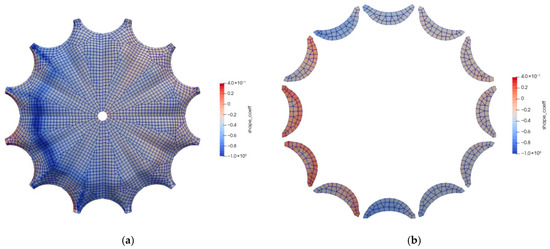
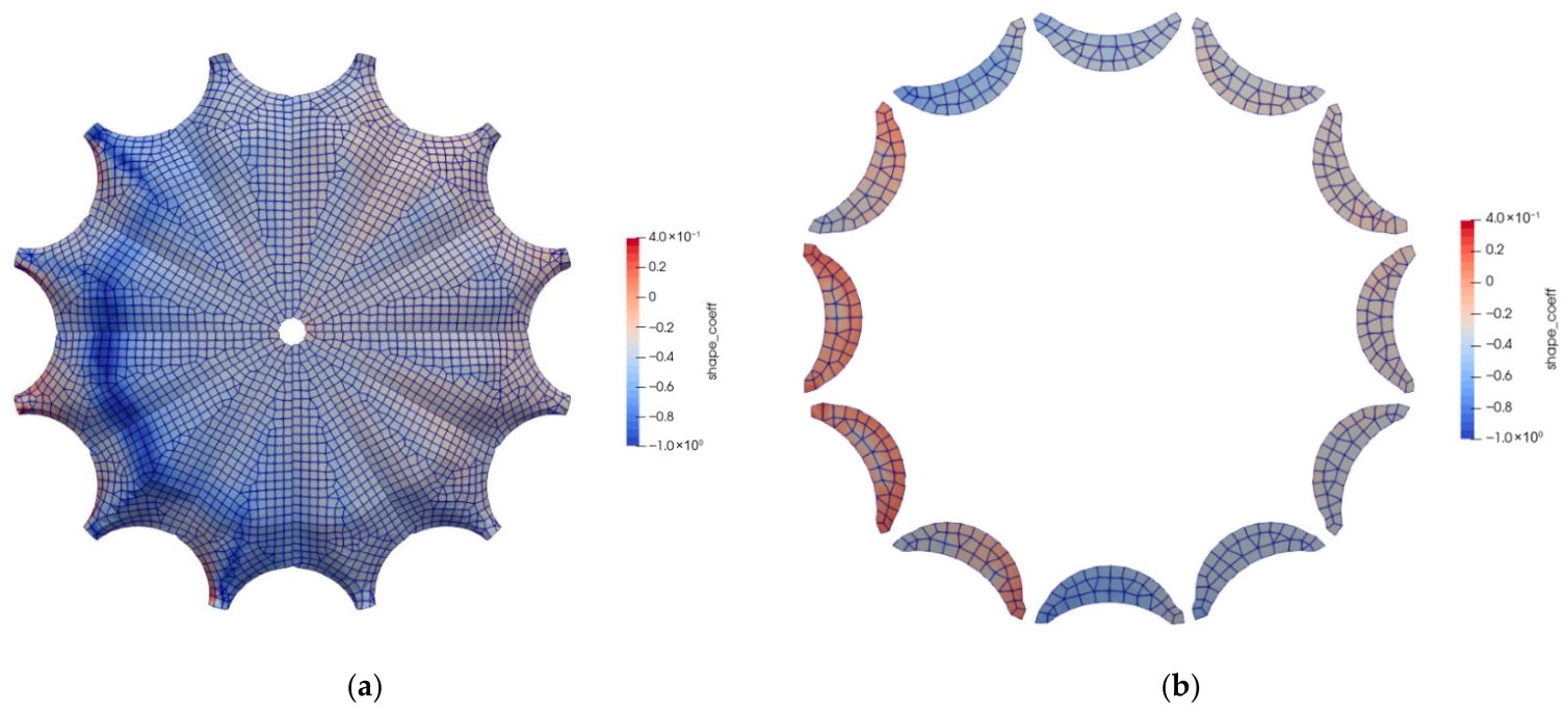
Figure 16 presents shape coefficient distributions for the closed-roof configuration at 15° wind direction angle: (a) movable roof section (= −1.12 at windward canopy projections), (b) fixed roof section (= −0.66 at mid-span). Figure 17 shows corresponding distributions for the open-roof configuration at the same 15° wind angle: (a) movable roof section (= −1.65 at annular edge), (b) fixed roof section (= −1.90 at leeward corner transition zone). Critically, the open configuration induces 47.3% and 188% greater suction magnitudes on the movable and fixed roof sections, respectively, compared to the closed configuration at identical wind incidence.
Figure 16.
Wind shape coefficient distribution on the roof from numerical wind tunnel simulation at 15° wind direction angle in closed configuration: (a) movable roof, (b) fixed roof.
Figure 17.
Wind shape coefficient distribution on the roof from numerical wind tunnel simulation at 15° wind direction angle in Open configuration: (a) movable roof, (b) fixed roof.
The newly added retractable roof structure is centrally symmetrical. Considering the more unfavorable wind directions of 0° and 15° based on wind tunnel test results, the maximum combined stress ratio on the roof under wind loads from the wind tunnel test is 0.89, occurring at the secondary ring beam near the junction with the decorative edge beam and the radial main beam. Specifically, the maximum stress ratio for the radial main beams is 0.55, for the inner ring beam is 0.45, and for the decorative edge beams is 0.60.
The maximum upward deformation of the roof is 10.1 mm under the 0° wind angle and 10.2 mm under the 15° wind angle, indicating minimal difference between the two cases.
5.3. Vertical Deformation
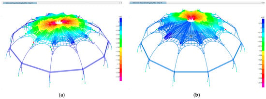
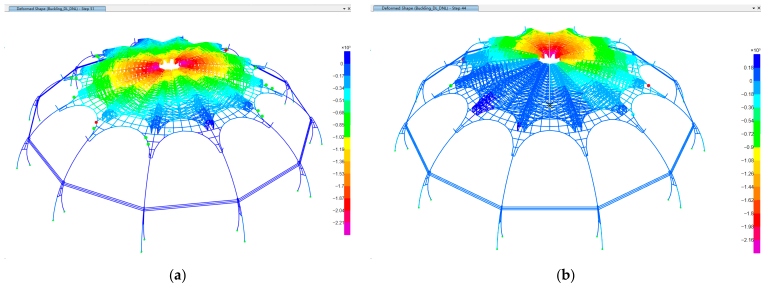
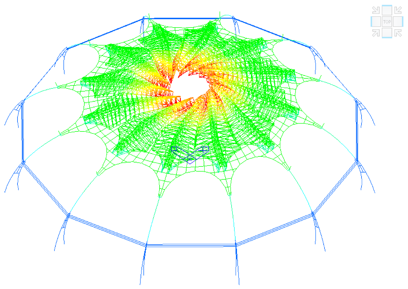
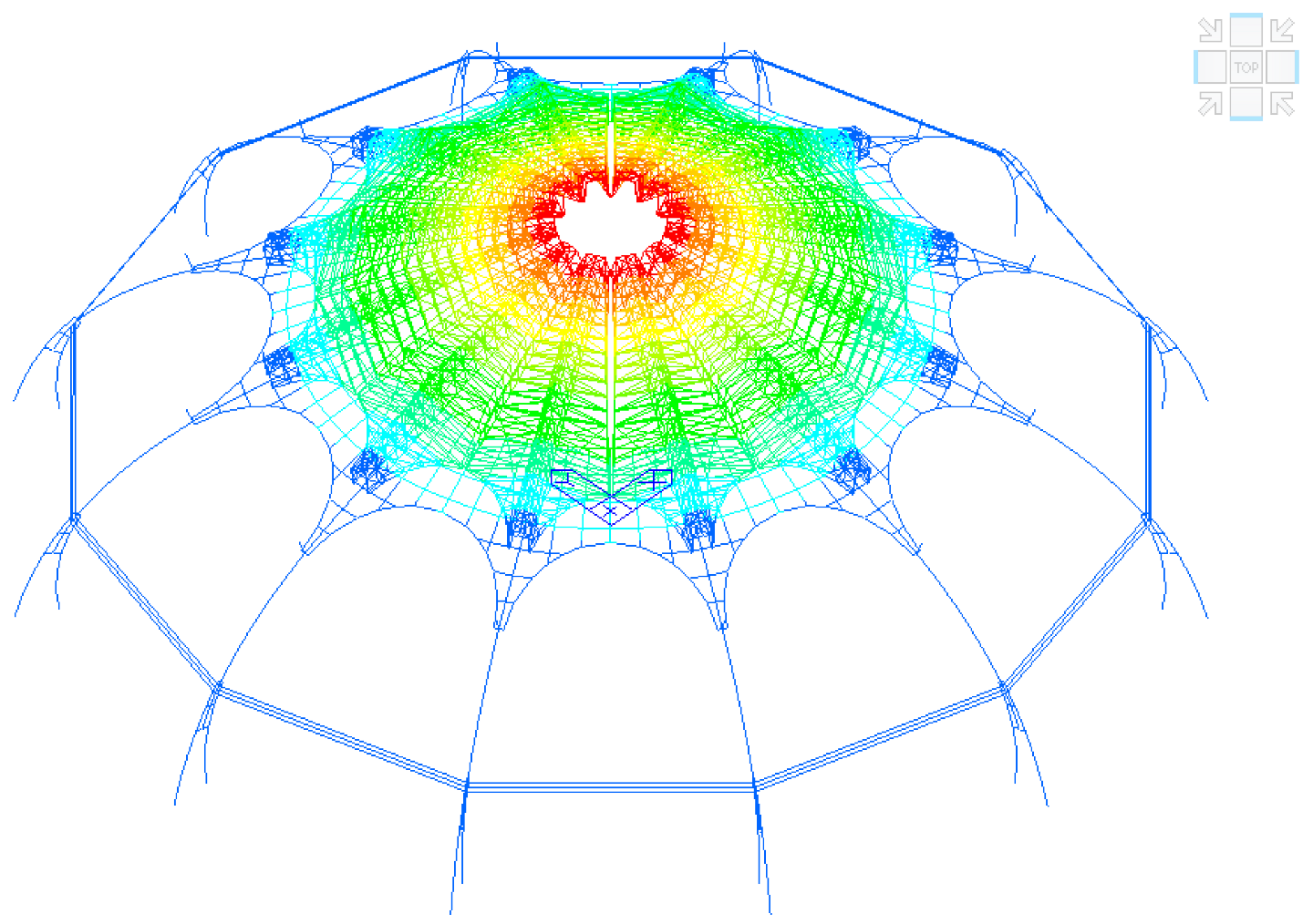
On the plane of the radial main beams in the integrated model under the closed configuration, the maximum vertical deformation of the fixed roof occurs at the intersection of the inner ring beam and the radial main beam, measuring 71 mm under dead load and 9 mm under live load. The maximum deformation of the movable roof occurs near the field center (innermost part), measuring 200 mm under dead load and 27 mm under live load. Due to the constraint provided by the inner ring beam, the middle section of the radial main beams bulges upward under dead load, with a maximum upward deformation of 9 mm occurring at approximately the one-third point near the root, as shown in Figure 18. Since the movable roof is connected to the fixed roof via a wheel–rail system, non-uniform deformation of the fixed roof at the supporting wheel locations induces rigid-body rotation of the movable roof, resulting in relatively large vertical deformations. Nevertheless, these deformations satisfy the limit of 227 mm < 46.43 m/200 = 232 mm. Furthermore, to meet architectural appearance and waterproofing requirements, an overall pre-cambering measure has been applied to both the movable and fixed roofs.
Figure 18.
Displacement contour plot for the critical state of double nonlinear stability analysis of the global assembly model: (a) dead load + full-span live load, (b) dead load + half-span live load.
5.4. Strength Verification
The stresses in key structural members of the integrated model under typical static load cases are presented in Table 8. As can be seen from the table, under vertical loads, the maximum stress of 126 MPa occurs at the inner ring beam in the closed configuration, while the maximum stress of 63 MPa in the Open configuration occurs in the decorative edge beams and the web members of the movable roof. Overall, the stress level under static loads is not high, indicating that strength is not the controlling factor, and the structural design is governed by stiffness requirements. The movable roof acts as an instantaneously unstable system, resulting in nearly zero stress under temperature action. This observation is consistent with the deformation results from the movable roof subassembly model and also verifies the reasonableness and reliability of the connection assumptions adopted in the integrated model.
Table 8.
The typical stresses of members in the integrated assembly model.
6. Stability Analysis
Stability analyses were performed using SAP2000 V25, employing the same geometric and material parameters as the Midas Gen model described in Section 4.1. The models were verified for consistency prior to analysis. Buckling modal analysis and geometric nonlinear analysis was conducted on the roof closed model, roof opened model, and roof half-opened model, respectively.
Comparative analysis indicates that increasing the cross-sections of the inner ring beam and the scalloped beams can enhance the global stability of the structure, with enlarging the inner ring beam section proving more effective. The load factor for the half-opened model is 17.8, differing by only 1.4 compared to the roof closed model (16.4). The decisive factor for the global stability of this project lies in the axial force within the inner ring beam. Under identical load cases, the axial force in the inner ring beam is 3657 kN for the closed model and 2991 kN for the half-opened model, showing a minor difference, which consequently leads to a small variance in their nonlinear stability results. The roof closed configuration exhibits the minimum linear elastic eigenvalue, while the minimum nonlinear load factor is 16.4, which is greater than 4.2.
The global stability of this project is primarily governed by the axial force in the inner ring beam. The maximum nonlinear load factors for the roof opened, closed, and half-opened states are 100.8, 16.4, and 17.8, respectively. The closed configuration (with full-span live load) represents the load case combination yielding the minimum nonlinear load factor.
Building upon this, dual nonlinear analysis was conducted. For the closed model under full-span live load, the load factor at the ultimate state from the dual nonlinear analysis is 5.8; for the closed model under half-span live load, the corresponding load factor is 4.6. Both values exceed 2.4, confirming that the global structural stability meets the requirements.
7. Collision Check Between New and Existing Structures
Based on the cross-sectional drawings of the existing roof and the newly added openable roof, the gap width between the new and existing structures at the lowest point of the existing roof is 253 mm. Under the standard load combination, the maximum in-plane deformation of the new roof at this location is 1.1 mm, while the deformation of the existing roof is 10.2 mm, resulting in a residual gap of 242 mm between the new and existing roofs after accounting for deformations. At the highest point of the existing roof, the gap width between the new and existing structures is 757 mm. Under the standard load combination, the maximum in-plane deformation of the new roof here is 78.4 mm, and the deformation of the existing roof is 24 mm, leaving a residual gap of 655 mm between the new and existing roofs after deformations. This spacing exceeds 250 mm, satisfying both the gap width requirements and installation operational requirements.
Based on the elastoplastic time history analysis described in Section 4.1 the maximum displacement under major earthquake (PGA = 220 cm/s2) actions were obtained as follows: the maximum displacement vector of the existing roof is 68 mm. and the maximum vertical displacement vector of the inner ring beam is 177.1 mm. At the location corresponding to the maximum deformation point of the existing roof, the displacement vector under major earthquakes is approximately 120 mm. After considering opposing deformations during a major earthquake, the minimum net clearance between the new and existing structures is 213 mm, and the maximum is 569 mm, indicating that collision will not occur. Regarding construction measures, appropriate pre-cambering can be applied as needed.
8. Conclusions
This study presents a comprehensive investigation into the retrofitting of an existing stadium with a retractable roof system, using the Ningbo (Yinzhou) Tennis Center as a case study. Through a combination of advanced numerical simulations, parametric analysis, and validation against design codes, the following conclusions are drawn:
- (1)
- Structural separation strategy proves effective in minimizing interference with the existing structure. By introducing expansion joints between the new and existing roof systems, the design eliminates unintended load transfer and accommodates differential deformations under both static and seismic conditions. This approach also simplifies the construction process and reduces the need for strengthening the original structure.
- (2)
- The selected rack-and-pinion drive system, chosen based on a comparative analysis of drive mechanisms considering compact spatial constraints, unit weight, track curvature, and synchronization requirements, ensures reliable operation under multi-state configurations. The kinematic analysis and reaction force calculations confirm that the drive system maintains continuous wheel–rail contact without impact loading during the entire opening and closing process.
- (3)
- The structural behavior of the retrofitted system is governed by the closed configuration, which imposes significantly higher demands on the fixed roof. Under dead load, vertical deformation in the closed configuration is approximately 3.7 times that in the open configuration, while the tensile force in the inner leg of the λ-shaped columns increases from 485 kN to 3223.7 kN. These findings highlight the necessity of using the closed state as the critical design condition.
- (4)
- The introduction of circumferential hoop cables at the top of the λ-shaped bifurcated columns effectively mitigates the outward bulging deformation of the radial main beams. With a selected cable force of 1050 kN, the tensile force in the inner leg is reduced to nearly zero, and the horizontal thrust in the outer leg decreases from 1315 kN to 905 kN in the closed configuration, thereby significantly lowering the force demands on the foundation.
- (5)
- A two-stage analytical framework—using both component-based sub-assembly models and an integrated assembly model—is essential for accurately capturing the mechanical behavior of the retrofitted system. While the sub-assembly model efficiently determines support reactions and enables independent verification of the fixed and movable roofs, the integrated model captures coupling effects and identifies the most vulnerable locations, such as the head of the movable roof under dynamic loading. This combined approach is recommended for future retrofit projects.
- (6)
- The retrofitted structure meets all applicable design requirements, including strength, stiffness, global stability, and seismic gap safety. Under major earthquake actions, the minimum net clearance between the new and existing structures remains 213 mm, well above the required safety margin. The nonlinear stability load factor of 4.6 exceeds the code requirement of 2.4, confirming adequate structural robustness.
- (7)
- The findings from this case study offer preliminary insights that may be considered for similar stadium retrofit projects. The design principles—including structural separation, drive system selection based on operational parameters, circumferential hoop cable-based self-equilibration for horizontal thrust mitigation, and the use of multi-level finite element modeling—can serve as a reference for other aging stadiums requiring functional upgrades and enhanced seismic performance.
- (8)
- Several limitations of this study should be acknowledged. The analysis is based on a single case study with specific geometric and seismic conditions; generalization of the findings to other stadium types, such as those with non-circular geometries or located in higher seismic zones, would require additional validation. The study does not include long-term operational monitoring data to validate the predicted structural responses under real-world conditions. Furthermore, while the proposed design addresses seismic demands, the long-term durability of the wheel–rail interface under repeated opening–closing cycles and potential maintenance requirements were not experimentally investigated and warrant further study. Future research should focus on developing standardized retrofit guidelines based on a broader range of case studies and on integrating real-time structural health monitoring systems to validate long-term performance.
Author Contributions
Conceptualization, S.J., S.S. and W.C.; Methodology, J.X. and S.S.; Software, J.X. and S.S.; Validation, J.X. and S.S.; Formal analysis, J.X. and S.S.; Investigation, J.X. and S.S.; Resources, S.J.; Data curation, J.X. and S.S.; Writing—original draft, J.X.; Writing—review & editing, S.J., S.S., R.L. and W.C.; Visualization, J.X. and S.S.; Supervision, S.J. and R.L.; Project administration, S.J. and R.L.; Funding acquisition, S.J. All authors have read and agreed to the published version of the manuscript.
Funding
This research work was financially supported by the Research Funds of Arcplus Group PLC (25-1-0150).
Data Availability Statement
The data used to support the findings of this study can be obtained from the corresponding author upon request.
Conflicts of Interest
Authors Shuizhong Jia, Jianli Xu, Shuo Shi and Ruixiong Li were employed by the company Shanghai Institute of Architectural Design & Research. The remaining author declares that the research was conducted in the absence of any commercial or financial relationships that could be construed as a potential conflict of interest. The authors declare that this study received funding from Arcplus Group. The funder was not involved in the study design, collection, analysis, interpretation of data, the writing of this article or the decision to submit it for publication.
References
- Kassabian, P.E.; You, Z.; Pellegrino, S. Retractable roof structures. Proc. Inst. Civ. Eng. Struct. Build. 1999, 134, 45–56. [Google Scholar] [CrossRef] [Scilit]
- Fan, Z.; Peng, Y.; Zhang, K.W.; Hu, C.Y.; Zhao, C.J.; Xie, P. New progress in retractable roof structures and technical standards. Steel Constr. (Chin. Engl.) 2020, 35, 29–65. [Google Scholar] [CrossRef]
- Irwin, H.P.A.H.; Wardlaw, R.L. A Wind Tunnel Investigation of a Retractable Fabric Roof for the Montreal Olympic Stadium; National Research Council Canada: Ottawa, ON, Canada, 1979; pp. 19–33. [Google Scholar]
- Tanno, Y.; Sasaki, Y.; Nakai, M. Fukuoka Dome. Struct. Eng. Int. 1994, 4, 151–153. [Google Scholar] [CrossRef] [Scilit]
- Pulley, J. Mercedes-benz stadium: Creating a mechanical marvel. Eng. Syst. 2019, 36, 24–27. [Google Scholar]
- Luo, Y.; Xue, Y. Recent development and engineering practices of space grid structures in China. Int. J. Space Struct. 2024, 39, 36–49. [Google Scholar] [CrossRef] [Scilit]
- Wang, K.; Wang, X.; Wu, Z.; Gao, P. Experimental and numerical study on collision responses of large-span retractable roof structure. J. Constr. Steel Res. 2025, 235, 109920. [Google Scholar] [CrossRef] [Scilit]
- Xu, W.; Zheng, X.; Shen, Y.; Luo, Y. Dynamic wireless sensor network-based structural health monitoring system for retractable roof structure. J. Build. Eng. 2024, 98, 111302. [Google Scholar] [CrossRef] [Scilit]
- Akgün, Y.; Gantes, C.J.; Kalochairetis, E.K.; Kiper, G. A novel concept of convertible roofs with high transformability consisting of planar scissor-hinge structures. Eng. Struct. 2010, 32, 2873–2883. [Google Scholar] [CrossRef] [Scilit]
- Mira, L.A.; Thrall, A.P.; De Temmerman, N. Deployable scissor arch for transitional shelters. Autom. Constr. 2014, 43, 123–131. [Google Scholar] [CrossRef] [Scilit]
- Hoberman, C. Radial Expansion/Retraction Truss Structures. U.S. Patent 5024031A, 18 July 1991. [Google Scholar]
- You, Z.; Pellegrino, S. Foldable bar structures. Int. J. Solids Struct. 1997, 34, 1825–1847. [Google Scholar] [CrossRef] [Scilit]
- Lu, J.; Hou, J.J.; Lu, D.; Liu, J. Study on the mechanical properties of the Miura-ori inspired retractable roof structure. Structures 2025, 77, 109040. [Google Scholar] [CrossRef] [Scilit]
- Zhu, Y.; Filipov, E.T. Large-scale modular and uniformly thick origami-inspired adaptable and load-carrying structures. Nat. Commun. 2024, 15, 2353. [Google Scholar] [CrossRef] [Scilit]
- Pawlak-Jakubowska, A.; Romaniak, K. Kinematics of the retractable roofing module constructed from three roof panels with stiffening of the central panel. Structures 2021, 29, 1078–1095. [Google Scholar] [CrossRef] [Scilit]
- Cai, J.; Feng, J.; Jiang, C. Development and analysis of a long-span retractable roof structure. J. Constr. Steel Res. 2014, 92, 175–182. [Google Scholar] [CrossRef] [Scilit]
- Wang, K.; Wang, X.; Wu, Z.; Gao, P. Analysis of motion performance of translational large-span retractable roof structure. Structures 2025, 79, 109488. [Google Scholar] [CrossRef] [Scilit]
- Liu, M.; Li, Q.S.; Huang, S.H.; Shi, F.; Chen, F. Evaluation of wind effects on a large span retractable roof stadium by wind tunnel experiment and numerical simulation. J. Wind Eng. Ind. Aerodyn. 2018, 179, 39–57. [Google Scholar] [CrossRef] [Scilit]
- Wang, K.; Wang, X.; Wu, Z.; Gao, P. Experimental and numerical study on seismic performance of translational large-span retractable roof structure. J. Build. Eng. 2025, 112, 113696. [Google Scholar] [CrossRef] [Scilit]
- Cai, J.; Zhou, Y.; Zhu, Y.; Feng, J.; Xu, J.; Zhang, J. Geometry and mechanical behaviour of radially retractable roof structures during the movement process. Int. J. Steel Struct. 2016, 16, 755–764. [Google Scholar] [CrossRef] [Scilit]
- Xu, G.M.; Wang, K.C.; Wang, B.G.; Feng, L.; Zha, X.X. The influence of initial geometric imperfections of track beams on the operation of movable roofs. Prog. Steel Build. Struct. 2025, 27, 84–92. [Google Scholar]
- Allen, C.M.; Duchesne, D.P.J. Toronto skydome retractable roof stadium-the roof concept and design. In Proceedings of the ASCE 7th Structures and Pacific Rim Engineering Congress; ASCE: New York, NY, USA, 1989; pp. 155–164. [Google Scholar]
- Pawlak-Jakubowska, A.; Romaniak, K. Kinematics of the retractable roofing module constructed from three roof panels. J. Build. Eng. 2021, 38, 102169. [Google Scholar] [CrossRef] [Scilit]
- Ma, S.; Lu, K.Y.; Hu, S.K.; Tang, J.K.; Liu, H.J.; Yuan, X.F. Design and experimental study of a clustered cable-truss retractable roof structure. Structures 2025, 72, 108237. [Google Scholar] [CrossRef] [Scilit]
- Carmelianda, N.; Kridarso, E.R.; Iskandar, J.; Novianthi, S. Comparison of dynamic elements on football stadium retractable roof case study: Singapore national stadium in Singapore, Toyota stadium in Japan, and Commerzbank arena in Germany. Int. J. Sci. Technol. Res. 2020, 9, 334–338. [Google Scholar]
- Hladik, P.; Lewis, C.J. Singapore National Stadium Roof. Int. J. Archit. Comput. 2010, 8, 257–278. [Google Scholar] [CrossRef] [Scilit]
- Wang, T.Y.; Pan, S.Y.; Huang, Y.C.; Luo, X.L.; Gu, F. Structural design of the cantilevered retractable roof for Jiaxing Culture and Art Center. Build. Struct. 2021, 51, 314–320. [Google Scholar]
- Wu, Y.R.; Ma, C.Y.; Miao, P.Y.; Han, X.T.; Liu, Y. Influence of opening rate and opening position on wind load and aerodynamic stability of long-span truss roof structure. J. Fluids Struct. 2025, 133, 104268. [Google Scholar] [CrossRef] [Scilit]

Disclaimer/Publisher’s Note: The statements, opinions and data contained in all publications are solely those of the individual author(s) and contributor(s) and not of MDPI and/or the editor(s). MDPI and/or the editor(s) disclaim responsibility for any injury to people or property resulting from any ideas, methods, instructions or products referred to in the content. |
© 2026 by the authors. Licensee MDPI, Basel, Switzerland. This article is an open access article distributed under the terms and conditions of the Creative Commons Attribution (CC BY) license.