


Abstract
The stability of underground building foundations in fractured rock masses is a critical concern in geotechnical engineering, particularly for urban projects situated in complex geological settings. In such environments, the interaction between weak planes, groundwater seepage, and in situ stress plays a decisive role in controlling deformation and failure mechanisms. This study presents a novel weak plane–seepage–stress coupling model specifically developed to evaluate the stability of underground excavations and foundation walls under these challenging conditions. Unlike conventional approaches that often assume isotropy or consider isolated factors, the proposed model integrates multiple interacting variables—including weak plane orientation, seepage coefficient, and excavation direction—to systematically assess their combined influence on stress redistribution and failure pressure. A key innovation lies in the quantitative evaluation of the permeability-sealing coefficient, which reflects the effectiveness of waterproofing measures, and its coupling with weak plane characteristics. The results demonstrate that weak planes significantly alter the surrounding stress field, inducing directional instability. The optimal excavation orientation for minimizing instability is identified within the range of 200° to 280°. Moreover, increasing δ from 0 to 1 leads to a substantial reduction in the required supporting pressure, underscoring the critical role of effective sealing and waterproofing in enhancing foundation stability. While the current model is based on a single weak plane assumption and focuses on short-term mechanical responses, it provides a foundational framework for understanding coupled instability mechanisms. Future work will extend the model to incorporate multi-set weak planes, time-dependent degradation, and dynamic excavation processes. This research offers both theoretical insights and practical guidance for optimizing geotechnical design in fractured rock environments, contributing to more resilient and sustainable underground construction.
1. Introduction
The rapid expansion of underground spaces in modern cities has led to an increasing need for safe design and long-term stability assessment of underground structures such as tunnels, retaining walls, and deep foundations. These structures are commonly situated in fractured and anisotropic rock masses, where the coupled interaction among in situ stress, groundwater seepage, and weak structural planes critically influences deformation and failure behavior. A thorough understanding of these coupled processes is essential for ensuring structural integrity and hydro-mechanical safety in complex geological settings [1,2,3,4,5]. Conventional analytical and empirical approaches often rely on isotropic assumptions or linear elastic solutions, thereby overlooking the inherent anisotropy and hydraulic–mechanical coupling characteristic of fractured rock systems. Such simplifications can result in substantial discrepancies between theoretical predictions and observed engineering performance. Recent advancements in numerical modeling and laboratory testing have revealed that seepage flow alters the effective stress state, thereby accelerating time-dependent deformation and failure [6,7,8,9,10]. Moreover, weak planes and structural discontinuities—such as bedding planes, joints, and faults—can promote strain localization and lead to asymmetric deformation zones around underground excavations [11,12,13,14,15,16].
The shear and slip behavior along weak structural planes has been a major focus in geomechanics. Zhang et al. [17] employed discrete element simulations and neural network modeling to demonstrate that anisotropic structural planes exhibit significant size effects and roughness-dependent variations in shear strength. These anisotropic failure mechanisms are particularly relevant to the stability of foundations and tunnels, where mechanical discontinuities govern shear resistance. In a related context, Zhang et al. [18] conducted pseudo-static and dynamic analyses of seismic earth pressures on retaining walls, revealing that resonance between the excitation frequency and the natural frequency of the wall can amplify dynamic stresses and compromise safety margins. These findings underscore the importance of incorporating both construction-induced effects and dynamic–static coupling into contemporary underground design. Beyond these contributions, coupled hydro-mechanical and thermo-hydro-mechanical (THM) analyses have become increasingly prominent in predicting excavation-induced failure. Studies by Dong et al. [19] and Jiang et al. [20] have shown that seepage-induced changes in pore pressure significantly alter stress paths and trigger progressive damage in fractured formations [21,22,23,24,25,26]. Similarly, Cheng et al. [27] and Cui et al. [28] introduced novel numerical frameworks for fracture-network coupling, illustrating how anisotropic permeability and contact behavior jointly influence fluid flow and deformation [29,30,31,32,33,34,35]. Despite these advances, most existing models still assume either isolated weak planes or isotropic permeability, which limits their applicability to real-world fractured foundations where multiple, interacting weak sets are present [36,37,38,39,40,41]. Moreover, the coupling between seepage sealing efficiency—i.e., permeability reduction due to grouting or waterproof layers—and the orientation of weak planes remains underexplored, even though this interaction is critically important in urban underground construction [42,43,44,45,46,47].
To address these challenges, this study establishes a weak plane–seepage–stress coupling model for underground foundations in fractured rock masses. The model integrates weak-plane orientation, permeability coefficient, and excavation direction to analyze asymmetric stress redistribution and failure patterns [47,48,49,50,51,52]. By quantitatively evaluating the role of sealing efficiency in stability enhancement, the framework provides practical guidance for optimizing excavation direction, waterproofing strategies, and support system design—thus contributing to safer and more sustainable underground development in complex geological conditions.
2. Methodology
2.1. Stress–Seepage Model for Underground Foundations
In geotechnical design, understanding the mechanical and hydraulic behavior of rock and soil is essential for evaluating the stability of underground foundations. This study develops a coupled stress–seepage model to assess the stability of underground excavations and foundation walls in fractured rock masses subjected to complex geological conditions. The model incorporates the combined effects of in situ stresses, external hydraulic loads, and pore pressure variations induced by groundwater seepage. The surrounding rock mass is idealized as a linear-elastic porous medium undergoing small deformations, with the formation assumed to be homogeneous and isotropic for simplicity. The deformation behavior is analyzed under plane-strain conditions, enabling an accurate characterization of the stress distribution around the excavation boundary [53,54,55,56].
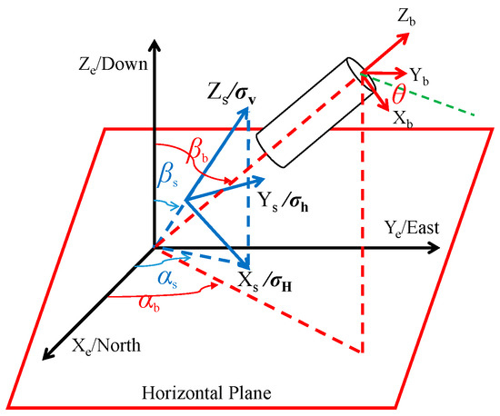
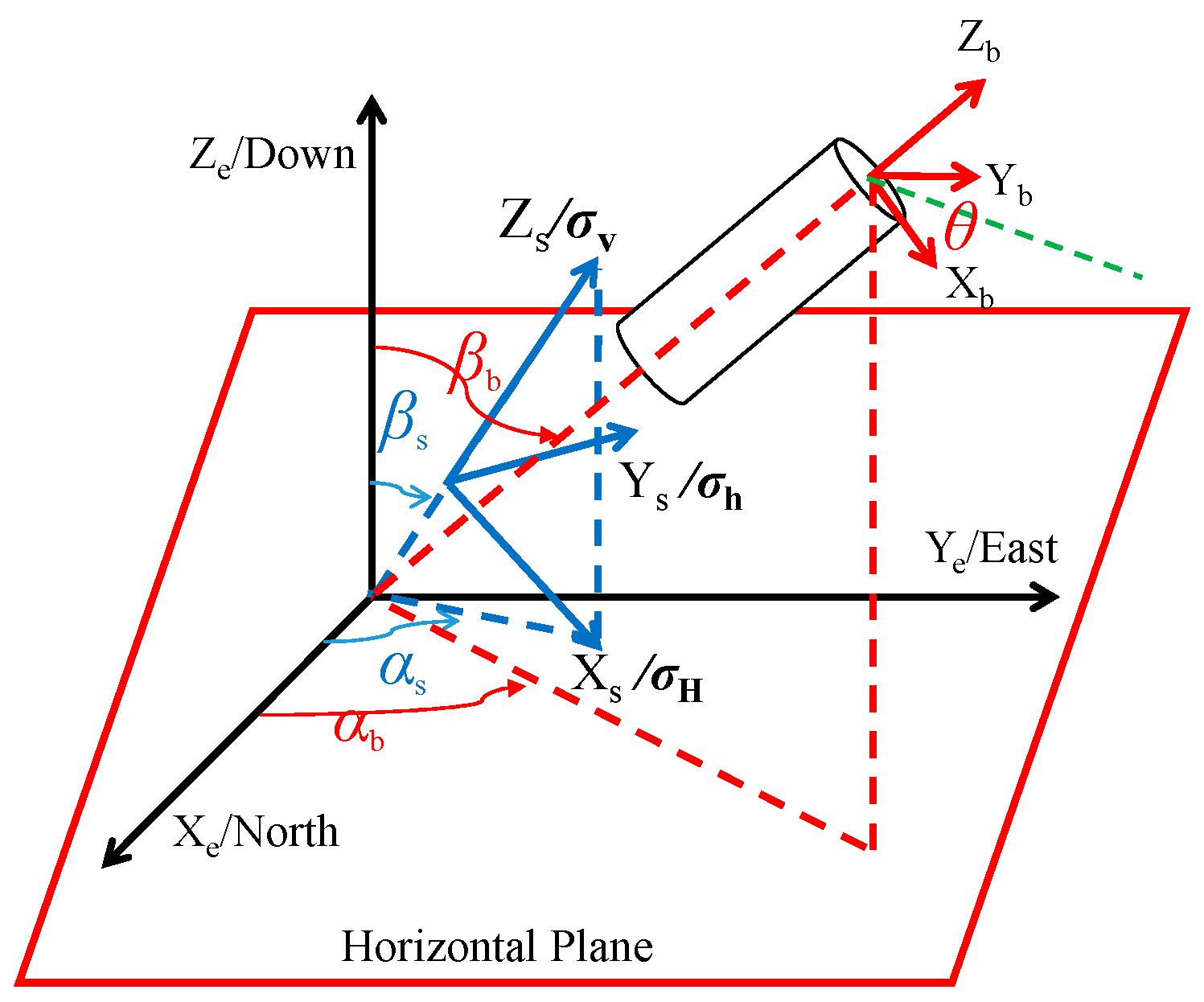
The coordinate transformation between the in situ stress field, the global coordinate system, and the local polar coordinate system around the excavation boundary is depicted in Figure 1. Under non-axisymmetric stress states, the stress components acting on the excavation wall are derived based on this transformation, as shown in Equation (1). This coupled model enables a comprehensive understanding of the interaction between stress and seepage effects, crucial for optimizing foundation stability and excavation designs in complex fractured environments.
where represent the stress components acting on the excavation wall in the local polar coordinate system in MPa; denote the components of the in situ stress field transformed into the local Cartesian coordinate system in MPa; is the external hydraulic pressure applied along the excavation boundary, induced by groundwater or construction loads in MPa; represents the pore pressure within the surrounding rock or soil mass in MPa; is the porosity of the formation, expressed as a percentage in %; is the permeability or seepage coefficient, a dimensionless parameter describing the sealing efficiency of the surrounding medium; is the circumferential angle around the excavation boundary in °; and K is the seepage–stress coupling coefficient, a dimensionless parameter.
Figure 1.
Relationship among the In Situ Stress Field, Global Coordinate System, Local Cartesian System, and Polar Coordinate System of the Excavation Boundary.
In which,
where v is the Poisson’s ratio of the formation rock, dimensionless; α is the Biot coefficient, dimensionless.
In the equation, represents the in situ stress, MPa; L is the stress transformation matrix that converts the global in situ stress field into the local Cartesian coordinate system of the underground excavation, as shown in Equation (4),
In the equation, denotes the excavation azimuth angle. In this study, the direction of the maximum horizontal in situ stress is taken as the reference direction, which points toward true north. Therefore, the excavation azimuth angle is defined as the angle between the projection of the excavation axis on the horizontal plane and the direction of the maximum horizontal in situ stress in °; represents the inclination angle of the excavation axis, defined as the angle between the excavation axis and the vertical direction or the direction of the vertical in situ stress in °; denotes the transpose matrix of the transformation matrix L.
2.2. Strength Criterion of Weak Structural Planes
The strength behavior of rock masses, particularly those containing weak structural planes, is a critical factor in assessing the stability of underground foundations. The first anisotropic strength criterion for rock masses was introduced by Jaeger in 1960 through the single weak structural plane model [57,58,59,60]. This model assumes that failure in layered or jointed rock masses can occur via two distinct mechanisms, i.e., shear slip along pre-existing weak or bedding planes and failure of the intact rock matrix between such planes.
When failure takes place within the intact rock matrix, the Mohr–Coulomb failure criterion governs the behavior, as expressed in Equation (5). This failure mechanism is essential for accurately predicting stress distributions and the overall stability of underground structures, as the interaction between weak planes and intact rock plays a key role in determining the strength and failure behavior of fractured foundations.
The maximum and minimum principal stresses are denoted by σ1 and σ3, respectively.
The cohesion and internal friction angle of the intact rock matrix are represented by S0 and , respectively.
Shear-slip failure along weak or bedding planes occurs when the applied shear stress exceeds the shear resistance of the structural planes. The critical stress condition for this mode of failure can be described using the Coulomb shear strength criterion, as expressed in Equation (6),
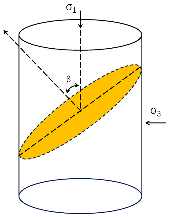
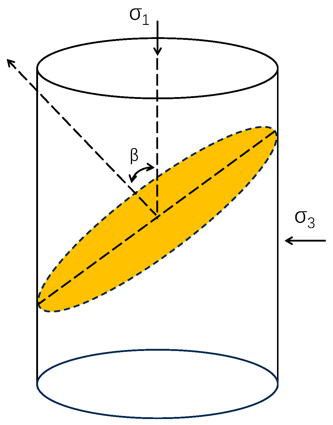
In which Sbp denotes the cohesion of the weak (or bedding) plane (MPa); is the internal friction angle of the weak plane (°); and β represents the angle between the direction of the applied principal stress and the normal to the weak plane, as illustrated in Figure 2.
Figure 2.
Diagram of bedding plane dip angle.
2.3. Stability Evaluation Model for Underground Excavation
Considering the development of structural fractures within the surrounding rock, it is assumed that the rock failure behavior follows the weak structural plane strength criterion, which accounts for the presence of pre-existing discontinuities [61]. The minimum and maximum principal stresses acting on the excavation boundary in the cylindrical coordinate system of an inclined underground excavation can be expressed as shown in Equations (7) and (8),
The angle between the maximum principal stress acting on the excavation boundary and the z-axis can be expressed by Equation (9),
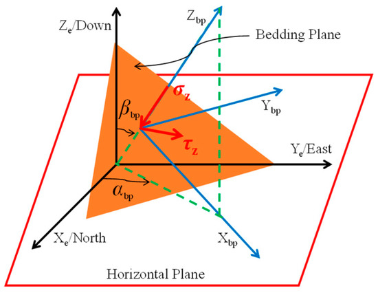
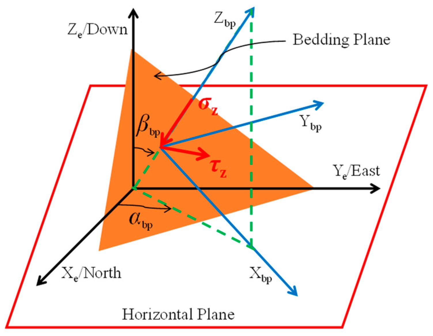
In rock masses containing well-developed structural fractures, it is crucial to assess whether the surrounding rock will fail along these discontinuities. To evaluate this, it is first necessary to establish the geometric relationship between the fracture orientation and the in situ stress field. This requires defining a local coordinate system for the fracture plane within the global (geodetic) coordinate system. The stress state acting on the excavation boundary is then transformed into the fracture-plane coordinate system, which allows for the evaluation of potential shear or tensile failure along these structural planes. This transformation is essential for accurately predicting failure behavior and ensuring the stability of underground foundations in fractured rock environments.
Figure 3 illustrates the transformation relationship between the fracture plane and the global coordinate system, which is fundamental for assessing the interaction between in situ stresses and fracture orientation in stability analysis.
Figure 3.
Relationship between the Fracture Plane Coordinate System and the Global (Geodetic) Coordinate System.
According to Figure 3, the unit normal vector to the weak plane can be expressed by Equation (10),
In which, denotes the dip direction of the fracture or weak plane, i.e., the angle between the projection of the plane normal onto the horizontal plane and the direction of the maximum horizontal in situ stress in °; represents the dip angle of the fracture plane, defined as the angle between the plane normal and the vertical direction in°. The direction vector of the maximum principal stress acting on the excavation boundary in the local Cartesian coordinate system of the underground excavation can be expressed by Equation (11),
In which,
The angle between the maximum principal stress acting on the excavation boundary and the normal to the weak plane satisfies the relationship expressed in Equation (13),
For the weak-plane strength criterion, it is also necessary to determine whether the failure of the surrounding rock occurs as shear slip along the structural plane or as shear failure within the intact rock matrix. When the angle β between the maximum principal stress acting on the excavation boundary and the normal to the weak plane falls within the range < β < , shear-slip failure takes place along the weak plane. When the angle β is greater than or less than , failure occurs through the intact rock matrix.
Based on the geometric interpretation of the Mohr circle, the upper and lower limits of the angle between the maximum principal stress and the normal to the weak plane—which define the condition for shear slip along the plane—are functions of the internal friction angle of the weak plane, as expressed in Equation (14).
When the lower limit angle between the normal to the weak plane and the maximum principal stress approaches the internal friction angle of the weak (or bedding) plane, or when the upper limit angle approaches 90∘, the shear strength of the weak plane tends toward infinity. After obtaining the principal stresses acting on the excavation boundary, as well as the critical angles and , these parameters can be substituted into the weak-plane strength criterion. The critical support pressure required to maintain excavation stability can then be solved using Newton’s iterative method.
3. Results and Discussions
The analysis of the critical support pressure distribution is influenced by several geomechanical parameters, which are summarized as follows: the formation depth is 3980 m; the overburden pressure gradient is 2.23 MPa/100 m; the maximum and minimum horizontal in situ stress gradients are 2.44 MPa/100 m and 1.79 MPa/100 m, respectively; the pore pressure gradient is 1.12 MPa/100 m; the porosity is 8.5%; Biot’s coefficient is 0.85; Poisson’s ratio is 0.22; the rock matrix cohesion is 25.06 MPa, with an internal friction angle of 30.8°. For the weak plane, the initial cohesion is 9.03 MPa, the internal friction angle is 14.9°, and the dip angle and azimuth are 45° and 60°, respectively. The permeability coefficient at the excavation boundary is 0.6. These parameters were incorporated into the coupled stress–seepage model to assess the effect of fluid–rock interactions on the stability of the excavation boundary, as discussed in the following sections.
3.1. Influence of Structural (Formation) Fracture Planes
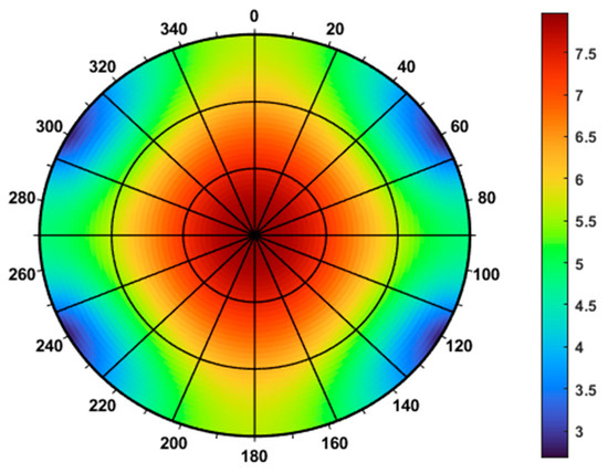
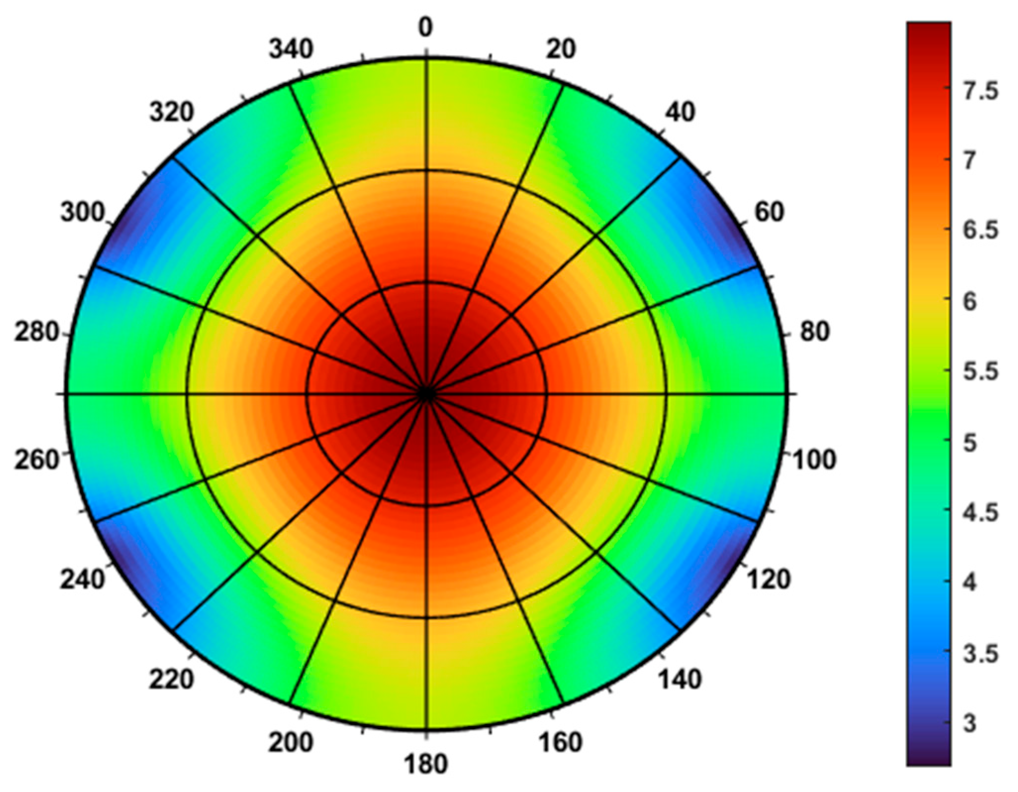
In the first scenario, where the influence of structural fractures is neglected and only seepage-induced stresses are considered, the Mohr–Coulomb strength criterion is applied to predict the critical support pressure. The polar distribution of the support pressure along the excavation boundary is presented in Figure 4. To investigate the effect of pre-existing fractures on the support pressure distribution, the weak-plane strength criterion is introduced while keeping all other parameters consistent with those used in Figure 4. The resulting polar plot is shown in Figure 5. In both figures, the color scale represents the magnitude of the critical support pressure, with colors ranging from dark blue to dark purple indicating a progressive increase in pressure. The circumferential direction corresponds to the excavation azimuth angle, where 0° aligns with the direction of the maximum horizontal in situ stress and 90° with the minimum horizontal in situ stress. The radial direction denotes the excavation inclination angle, with 0° representing a vertical excavation and 90° a horizontal excavation.
Figure 4.
Polar distribution of the critical support pressure along the excavation boundary based on the Mohr–Coulomb strength criterion.
Figure 5.
Polar distribution of the critical support pressure along the excavation boundary based on the weak-plane strength criterion.
As illustrated in the figures, the results predicted using the Mohr–Coulomb criterion show that the distribution of critical support pressure along the excavation boundary is symmetrical with respect to the directions of maximum and minimum horizontal in situ stresses.
As the excavation inclination angle increases, the required support pressure gradually decreases. Excavations with smaller inclination angles demand higher support pressure, while horizontal excavations exhibit relatively lower values. The pressure distribution is generally symmetric, with higher support pressures concentrated near the central region and decreasing toward the periphery—from approximately 7.5 MPa at the center to around 3 MPa at the outer boundary. The smooth color transition in the polar plot reflects a strongly axisymmetric pressure field, consistent with an idealized uniform loading or axisymmetric structural configuration. For horizontal excavations, the critical support pressure reaches its minimum near azimuths of 60°, 120°, 240°, and 300°, suggesting that excavations oriented along these directions offer the greatest structural stability. In contrast, the results obtained using the weak-plane strength criterion reveal significant asymmetry, which is strongly influenced by the orientation of the pre-existing weak structural plane (with a dip angle of 45° and an azimuth of 60°). For horizontal excavations within the azimuth range of 200–280°, the critical support pressure drops to a minimum of approximately 10 MPa, whereas outside this range, it rises sharply to over 35 MPa. The polar plot under this criterion exhibits non-uniform color transitions and multiple abrupt changes, indicating discontinuities or sharp variations in the pressure field. These discontinuities result from variations in the angle between the excavation axis and the weak-plane orientation. The comparison clearly demonstrates that the presence of structural fracture planes substantially alters the mechanical response of the surrounding rock mass, leading to a pronounced increase in the required support pressure. Therefore, the influence of weak planes on excavation stability cannot be overlooked in the design and construction of underground foundations.
3.2. Influence of Permeability Coefficient
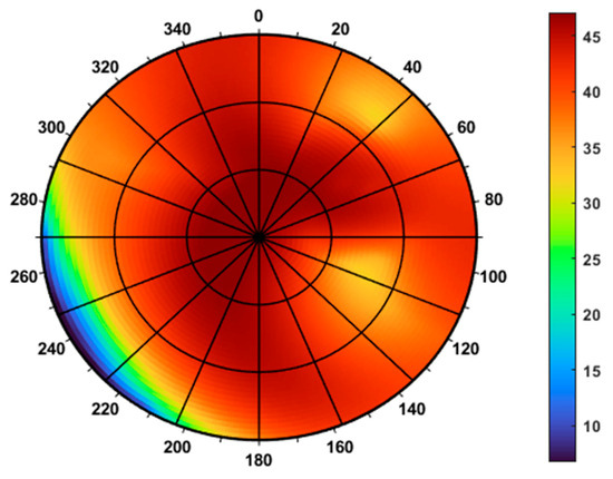
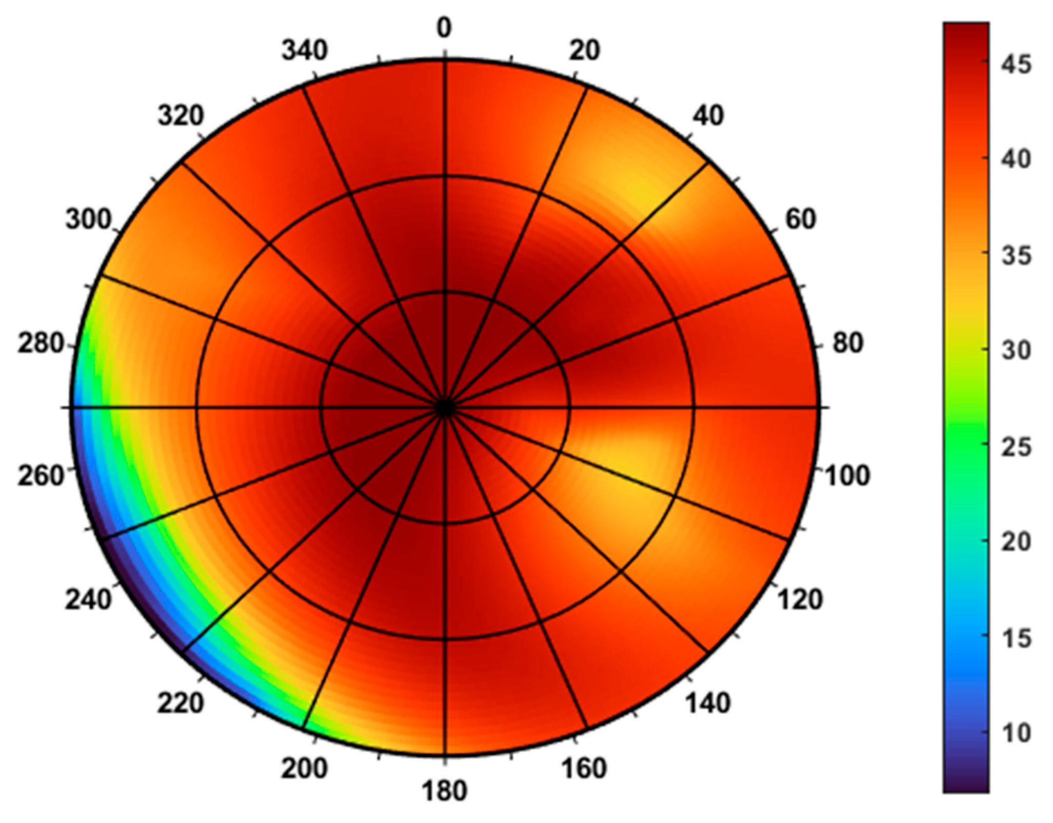
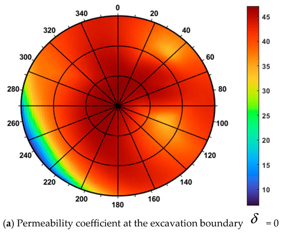
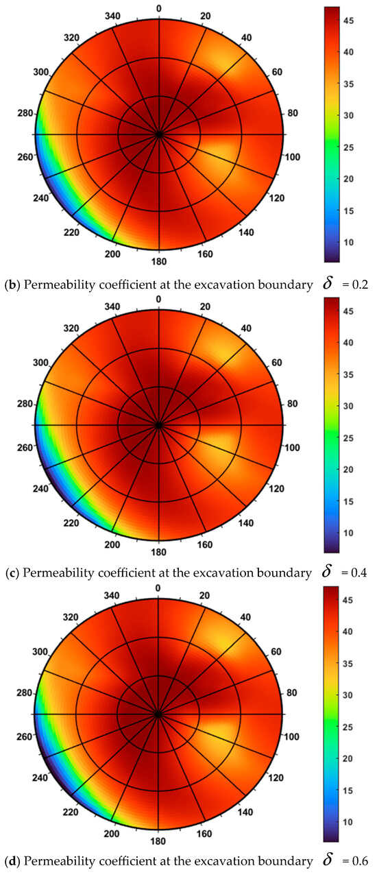
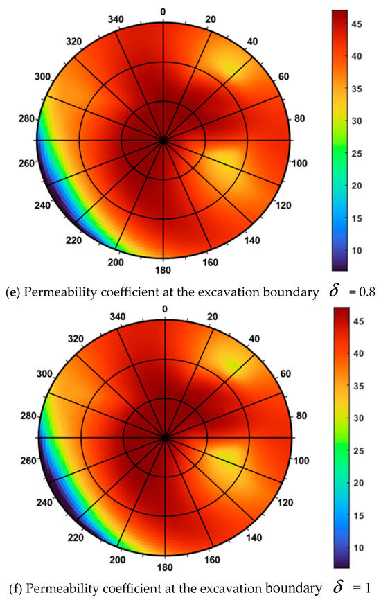
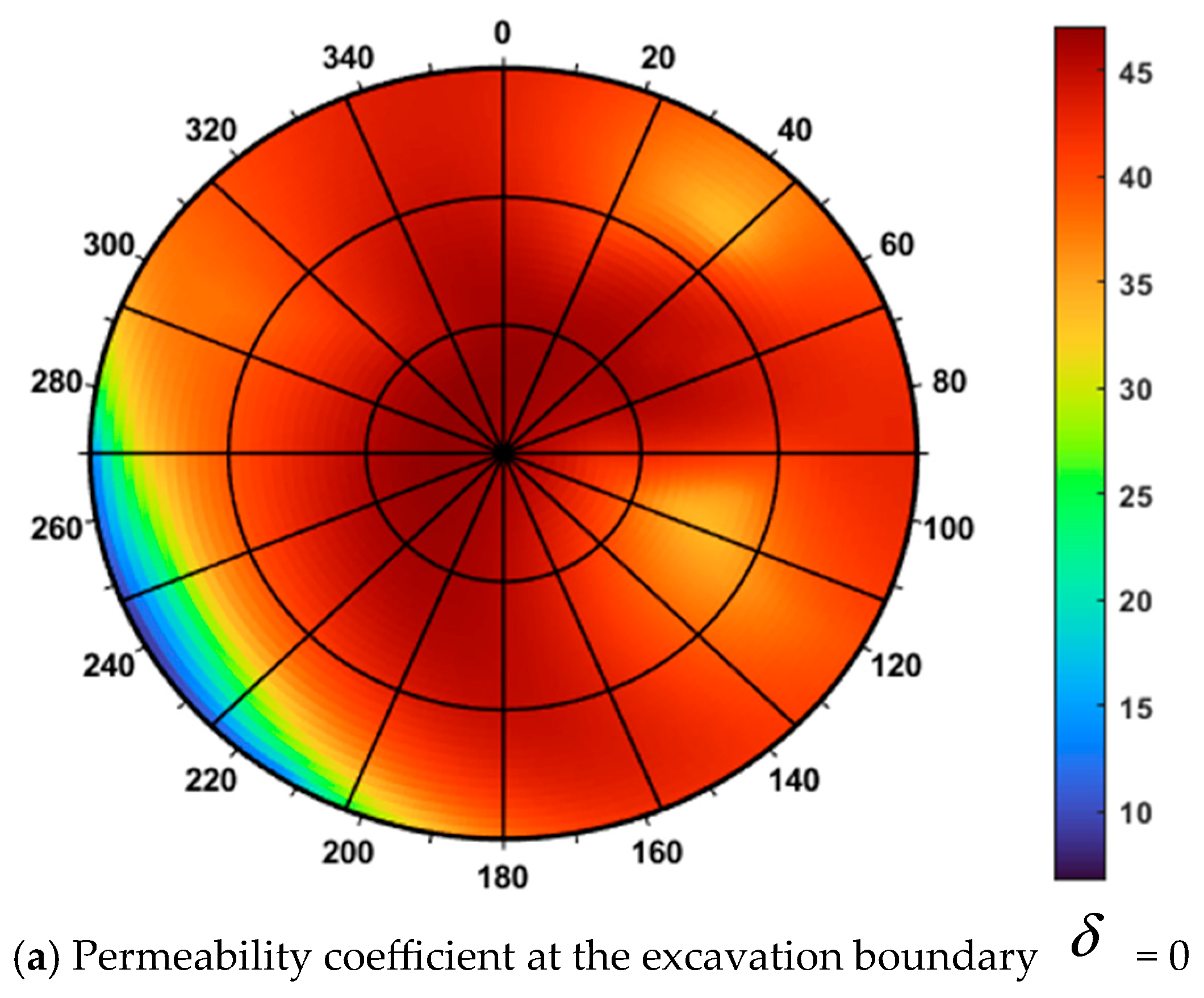
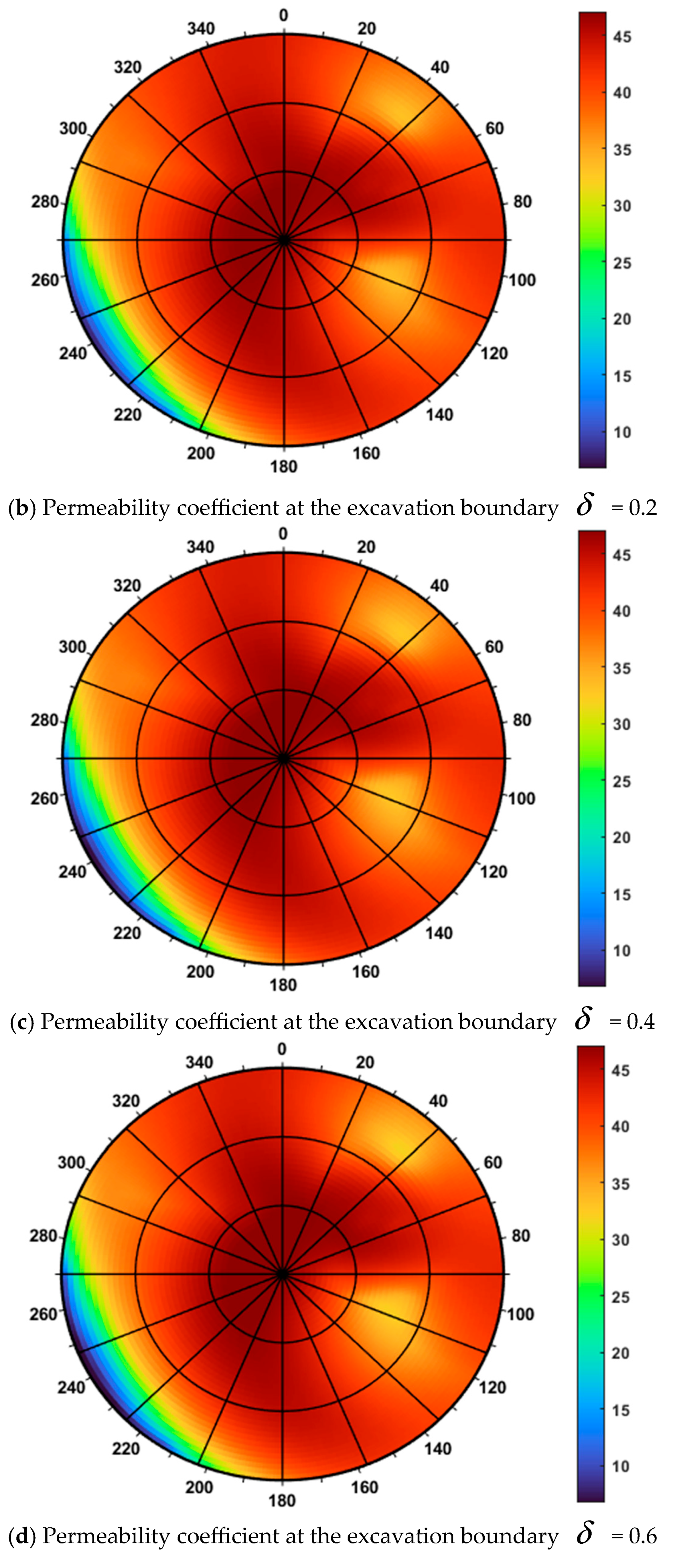
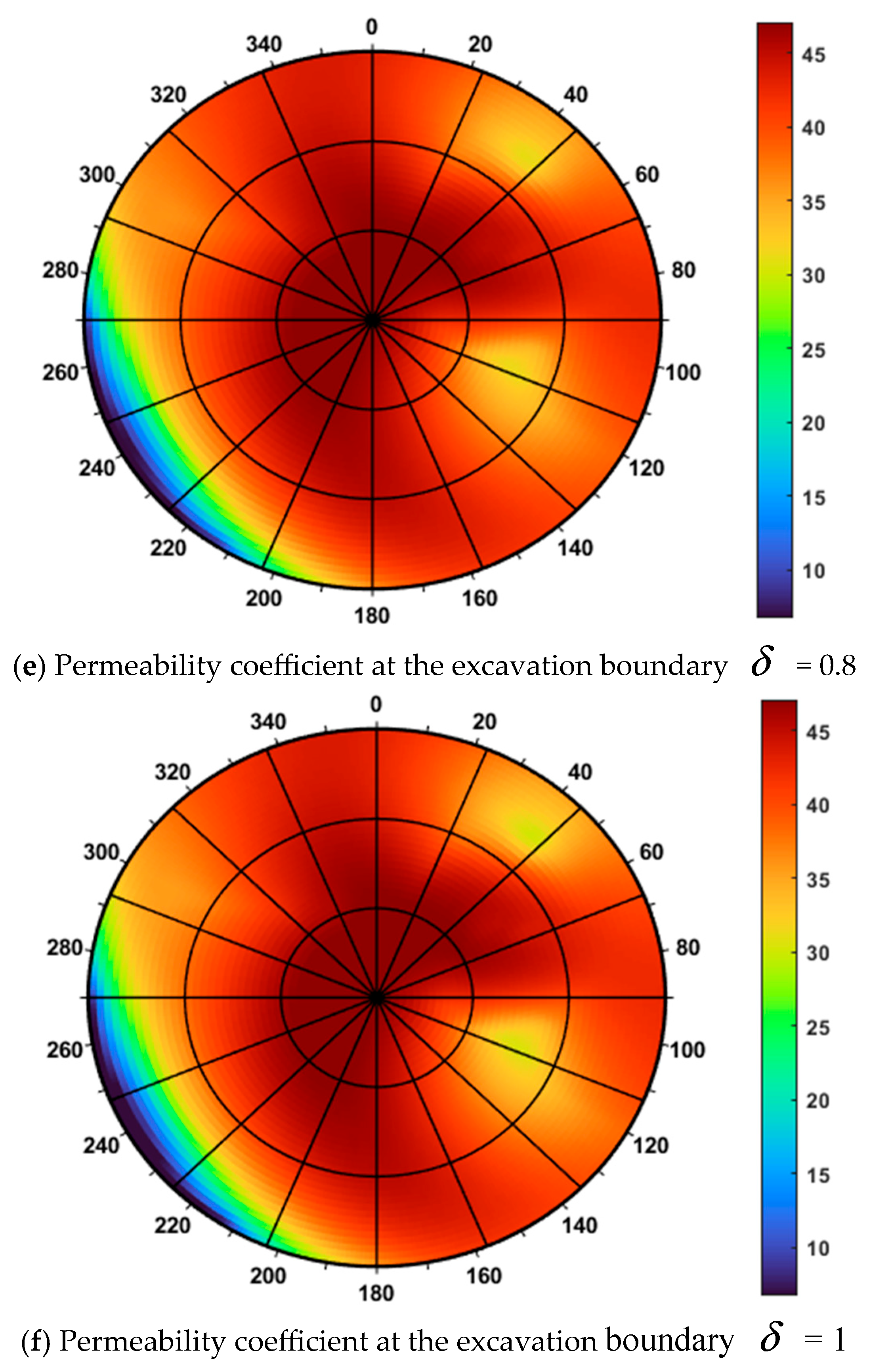
To investigate the influence of permeability on the support pressure distribution, the permeability coefficient at the excavation boundary was set to 0, 0.2, 0.4, 0.6, 0.8, and 1, while keeping all other parameters constant. The resulting polar plots of critical support pressure under different permeability conditions are shown in Figure 6.
Figure 6.
Influence of Fluid–Rock Interaction Efficiency on the Distribution of Critical Support Pressure.
The permeability coefficient at the excavation boundary plays a key role in characterizing the fluid–rock interaction efficiency and reflects the effectiveness of the sealing layer formed on the rock surface.
A lower permeability of the sealing layer corresponds to a lower permeability coefficient, indicating improved sealing performance. In this context, δ = 0 represents the case with no sealing layer, while δ = 1 denotes the formation of a completely impermeable layer. Figure 6 illustrates the critical support pressure for various permeability coefficients, with the values in the legend ranging from 6.75 MPa to 47.11 MPa for comparison. Key observations from Figure 6 include the following: as the permeability coefficient increases from 0 to 1, the critical support pressure gradually decreases, and the low-pressure zone expands. From Figure 6a–e, the dark-blue region expands outward, indicating a reduction in the required support pressure. When the sealing layer is fully developed, the corresponding critical support pressure distribution is presented in Figure 6f. To maintain excavation stability under this condition, the applied fluid or support pressure must exceed the predicted values shown in Figure 6e, thereby providing adequate confinement to the surrounding rock. Conversely, insufficient sealing performance leads to more pronounced seepage effects, resulting in increased pore pressure, reduced effective stress, and consequently, a higher required support pressure. This condition elevates the risk of excavation instability.
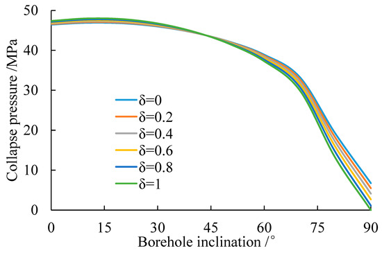
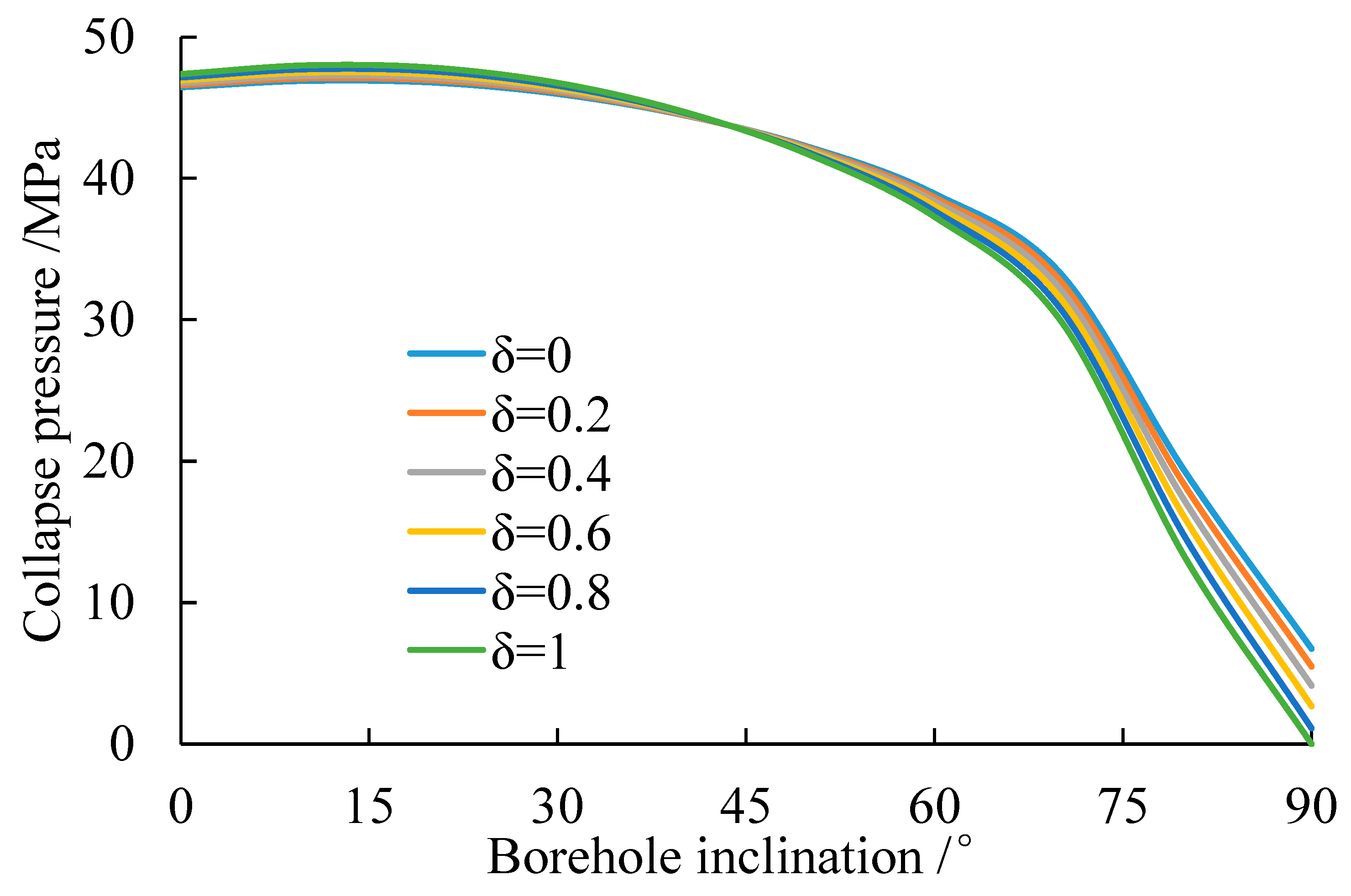
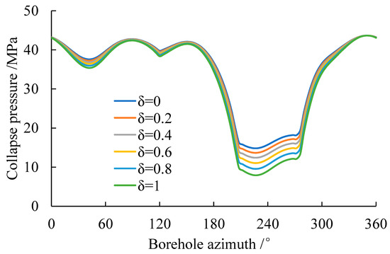
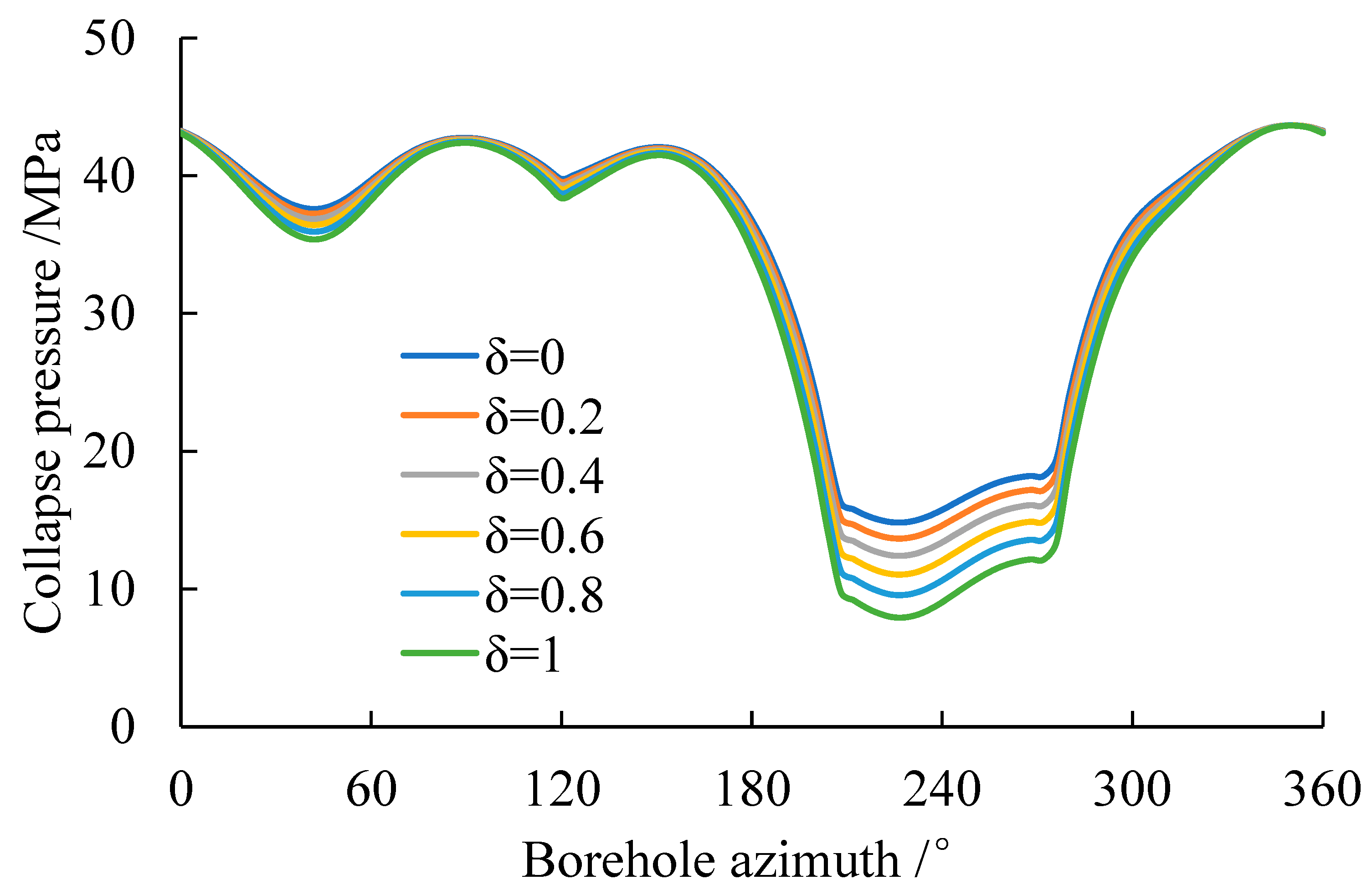
To quantitatively evaluate the impact of permeability at the excavation boundary on the critical support pressure, curves representing the variation in critical support pressure with excavation azimuth and inclination angle under different permeability coefficients are presented in Figure 7 and Figure 8. Regardless of variations in inclination angle (ranging from 0° to 90°) or azimuth (from 0° to 360°), the relative order of the curves for different δ values remains unchanged. The curve for δ = 0 (completely unsealed boundary) consistently occupies the highest position, indicating the greatest required support pressure, while the curve for δ = 1 (fully sealed boundary) lies at the lowest, corresponding to the minimum support pressure. The intermediate cases (δ = 0.2, 0.4, 0.6, 0.8) exhibit a sequential downward progression as δ increases, clearly demonstrating that improved sealing performance enhances excavation stability and substantially reduces the required support pressure. The rate of pressure reduction accelerates with increasing δ, with the most pronounced decrease occurring between δ = 0.8 and δ = 1. This suggests that the stability of the surrounding rock is highly sensitive to sealing efficiency, particularly under low-permeability conditions. In Figure 7, all curves display a general trend of gradually decreasing support pressure with increasing inclination angle. In Figure 8, the pressure exhibits distinct periodic fluctuations with azimuth, reaching peaks near 0° (or 360°) and troughs between 180° and 240°. The magnitude of the permeability coefficient δ governs the baseline level of these fluctuations: higher δ values correspond to lower baseline pressures. Effective sealing (i.e., higher δ) consistently reduces the required support pressure across all inclination and azimuth angles, thereby enhancing overall excavation stability.
Figure 7.
Variation in critical support pressure with excavation inclination angle for different seepage coefficients.
Figure 8.
Variation in critical support pressure with excavation azimuth angle for different seepage coefficients.
This finding underscores that, in practical underground engineering, improving the sealing performance of the excavation boundary is one of the most efficient and direct strategies to maintain structural stability and mitigate excavation-related risks.
4. Conclusions
This study established a weakly planar–seepage–stress coupling model to systematically investigate the stability of underground excavations in fractured rock masses. By incorporating weak-plane orientation, excavation trajectory, and sealing efficiency, the model provides a quantitative framework for understanding the coupled mechanisms governing support pressure and failure behavior. The main conclusions and innovations are as follows:
1. In contrast to traditional isotropic models, this study demonstrates that the weak-plane strength criterion results in a distinctly asymmetric distribution of critical support pressure. The orientation of weak planes is identified as the dominant controlling factor, with the minimum support pressure (~10 MPa) occurring for horizontal excavations within an azimuth range of 200–280°. This finding underscores the necessity of moving beyond isotropic assumptions in fractured rock masses.
2. The model quantitatively analyzes, for the first time, the combined effect of the sealing coefficient on excavation stability. The results show that increasing δ from 0 to 1 significantly reduces the required support pressure, thereby expanding the safe operating window. The most substantial reduction occurs between δ = 0.8 and δ = 1, highlighting that enhancing sealing efficiency to form a low-permeability surface layer is a highly effective strategy for improving safety.
3. The study reveals that as δ increases, regions of high support pressure progressively shift toward the dip direction of the weak plane. This dynamic interaction between the seepage field and structural plane geometry alters the effective stress path and potential failure modes, confirming that accurate modeling of anisotropic seepage–stress coupling is essential for reliable stability predictions in complex geological environments.
4. The coupled model, integrating coordinate transformation and multi-criteria strength assessment, offers a novel theoretical tool for optimizing excavation trajectories and fluid-support pressure design. The findings provide clear quantitative guidance: prioritizing excavation orientations aligned with the identified safe azimuth range and targeting a sealing efficiency of δ ≥ 0.8 can significantly enhance excavation stability in fractured strata.
While this study provides a robust theoretical foundation, it is based on the assumption of a single weak-plane set and static analysis. Future research should address these limitations by incorporating the interactions of multiple intersecting weak planes, the time-dependent deterioration of mechanical properties due to groundwater chemistry, and dynamic construction effects. Integrating these factors will further improve the model’s predictive capability and its application to the safe and sustainable development of complex underground infrastructure.
Author Contributions
Conceptualization, Y.W.; Methodology, Y.W.; Software, Z.W.; Validation, Z.W.; Formal analysis, Z.W. and L.Z.; Investigation, Y.W. and J.F.; Resources, Y.W., H.W. and J.F.; Data curation, Z.X. and H.W.; Writing—original draft, L.Z. and Z.X.; Writing—review & editing, L.Z.; Visualization, J.F.; Supervision, H.W.; Project administration, Z.X., H.W. and J.F.; Funding acquisition, L.Z. and Z.X. All authors have read and agreed to the published version of the manuscript.
Funding
The research is supported by Sichuan Province Science and Technology Support Program [No. 2024NSFSC2021].
Data Availability Statement
The data and materials used in this study are available upon request.
Conflicts of Interest
Authors Zhibo Wang, Zhiming Xu, Huaqing Wu and Jiang Feng were employed by the company PetroChina Tarim Oilfield Company, China National Petroleum Corporation (CNPC). The remaining authors declare that the research was conducted in the absence of any commercial or financial relationships that could be construed as a potential conflict of interest.
References
- Zhao, Y.; Liu, Q.; Lin, H.; Wang, Y.; Tang, W.; Liao, J.; Li, Y.; Wang, X. A Review of Hydromechanical Coupling Tests, Theoretical Models, and Applications. Water 2023, 15, 2309. [Google Scholar] [CrossRef] [Scilit]
- Fan, X.; Zhang, M.; Zhang, Q.; Zhao, P.; Yao, B.; Lv, D. Wellbore stability and failure regions analysis of shale formation accounting for weak bedding planes in Ordos basin. J. Nat. Gas Sci. Eng. 2020, 77, 103258. [Google Scholar] [CrossRef] [Scilit]
- Zhang, M.; Fan, X.; Zhang, Q.; Zhao, P. Influence of multi-planes of weakness on unstable zones near wellbore wall in a fractured formation. J. Nat. Gas Sci. Eng. 2021, 93, 104026. [Google Scholar] [CrossRef] [Scilit]
- Gao, M.; Gong, B.; Liang, Z.; Jia, S.; Zou, J. Investigation on the anisotropic mechanical response of layered shales. Energy Sci. Eng. 2023, 11, 4737–4754. [Google Scholar] [CrossRef] [Scilit]
- Shen, J.; Wang, H.; Zhou, B.; Hu, G.; Zhang, X.; Yang, B. Investigation of the effect of microbial-induced calcite precipitation treatment on bio-cemented calcareous sands using discrete element method. Comput. Geotech. 2023, 158, 105365. [Google Scholar] [CrossRef] [Scilit]
- Zhang, P.; Bai, R.; Sun, X.; Wang, T. Investigation of Rock Joint and Fracture Influence on Open-Pit Mining and Stability Under Coupled Stress–Seepage Conditions. Appl. Sci. 2023, 13, 10275. [Google Scholar] [CrossRef] [Scilit]
- Li, D.; Jiang, B.; Li, G.; Zhu, C. Design and Stability Evaluation of Slopes in the Sejiang Deformable Body Region Based on Experimental Data. Designs 2025, 9, 143. [Google Scholar] [CrossRef] [Scilit]
- Ma, W.-B.; Zou, W.-H.; Zhang, J.-L.; Li, G. Prediction of Shear Strength in Anisotropic Structural Planes Considering Size Effects. Designs 2025, 9, 17. [Google Scholar] [CrossRef] [Scilit]
- Fan, X.; Zhang, M.; Zhao, P.; Zhang, Q. Investigation of failure region around the wellbore based on the extended Mogi-Coulomb criterion for rock matrix. Geomech. Geoengin. 2022, 17, 372–383. [Google Scholar] [CrossRef] [Scilit]
- Salimzadeh, S.; Paluszny, A.; Zimmerman, R.W.; Nick, H.M. A three-dimensional coupled thermo-hydro-mechanical model for deformable fractured geothermal systems. Geothermics 2018, 71, 212–224. [Google Scholar] [CrossRef] [Scilit]
- von Planta, C.; Vogler, D.; Chen, X.; Nestola, M.G.C.; Saar, M.O.; Krause, R. Simulation of hydro-mechanically coupled processes in rough rock fractures using an immersed boundary method and variational transfer operators. Comput. Geosci. 2019, 23, 1125–1140. [Google Scholar] [CrossRef] [Scilit]
- Stebel, J.; Kružík, J.; Horák, D.; Březina, J.; Béreš, M. On the parallel solution of hydro-mechanical problems with fracture networks and contact conditions. Comput. Struct. 2024, 298, 107339. [Google Scholar] [CrossRef] [Scilit]
- Zhao, R.; Li, L.; Chen, X.; Zhang, S. Mechanical Response of Pipeline Leakage to Existing Tunnel Structures: Insights from Numerical Modeling. Buildings 2025, 15, 1771. [Google Scholar] [CrossRef] [Scilit]
- Zoback, M.D. Reservoir Geomechanics; Cambridge University Press: Cambridge, UK, 2007. [Google Scholar]
- Sun, Z.; Wang, W.; Liu, H. Pseudo-Static Design and Analysis of Seismic Earth Pressure for Cantilever Retaining Walls with Limitation Assessment. Designs 2025, 9, 114. [Google Scholar] [CrossRef] [Scilit]
- Zhang, M.; Fan, X.; Zhang, Q.; Yang, B.; Zhao, P.; Yao, B.; Ran, J. Parametric sensitivity study of wellbore stability in transversely isotropic medium based on poly-axial strength criteria. J. Pet. Sci. Eng. 2021, 197, 108078. [Google Scholar] [CrossRef] [Scilit]
- Zhang, M.; Li, D.; Liu, Y.C.K. The modification of Mohr-Coulomb criteria based on shape function and determination method of undetermined parameters. Mech. Mater. 2023, 185, 104772. [Google Scholar] [CrossRef] [Scilit]
- Zhang, X.; Li, J. Advancements and challenges of high-speed active flow control: Plasma actuators. Int. J. Heat Mass Transf. 2025, 252, 127481. [Google Scholar] [CrossRef] [Scilit]
- Dong, W.; Tian, J.; Chen, Q.; Wang, P.; Han, T.; Zhai, Y.; Jiang, D. Relationship between Shale Hydration and Shale Collapse. ACS Omega 2022, 7, 42524–42536. [Google Scholar] [CrossRef] [Scilit] [PubMed]
- Jiang, S.; Zhang, J.; Diao, K.; Liu, X.; Ding, Z. Research Advances in Solvent Extraction of Lithium: The Potential of Ionic Liquids. Adv. Funct. Mater. 2025, 35, 2423566. [Google Scholar] [CrossRef] [Scilit]
- Yang, M.; Si, S.; Zhang, K.; Xi, M.; Zhang, W. Bridging the relationship between physical exercise and mental health in adolescents based on network analysis. PsyCh J. 2024, 13, 835–848. [Google Scholar] [CrossRef] [Scilit]
- Rong, H.; He, L.; Li, N.; Wang, Z.; Kou, S. Technical research on surrounding rock control of roadways crossing collapse columns in strong mine pressure working faces. Sci. Rep. 2025, 15, 31905. [Google Scholar] [CrossRef] [Scilit]
- Ambrose, J.; Zimmerman, R.W.; Suarez-Rivera, R. Failure of shales under triaxial compressive stress. In Proceedings of the 48th U.S. Rock Mechanics/Geomechanics Symposium, Minneapolis, MN, USA, 1–4 June 2014; ARMA-2014-7756; American Rock Mechanics Association: Westminster, CO, USA, 2014. [Google Scholar]
- Cao, W.; Deng, J.; Wei, B.; Tan, Q.; Liu, W.; Li, Y. Genesis of wellbore-induced fractures based on porous media thermoelastic theory. Nat. Gas Ind. 2017, 37, 79–85. [Google Scholar]
- Chen, A.; Long, Z.; Zhou, Y.; Wang, Y.; Peng, X.; Cao, H. Discussion on low-cost drilling technology for horizontal wells in normal-pressure shale gas on the margin of Sichuan Basin. Pet. Drill. Tech. 2018, 46, 9–14. [Google Scholar]
- Chen, P.; Ma, T.; Xia, H. A prediction model for collapse instability of shale horizontal wells containing multiple groups of weak planes. Nat. Gas Ind. 2014, 34, 87–93. [Google Scholar]
- Cheng, Y.; Huang, R. Mechanical analysis of borehole stability in shale formation in drilling. J. Univ. Pet. China 1994, 18, 50–55. [Google Scholar]
- Cui, L.; Ekbote, S.; Abousleiman, Y. Effect of pore fluid conditions at the borehole wall on borehole stability. In ARMA/USRMS 1999, Proceedings of the 37th U.S. Symposium on Rock Mechanics (USRMS): Rock Mechanics for Industry, Vail, CO, USA, 7–9 June 1999; ARMA-99-0187; American Rock Mechanics Association: Westminster, CO, USA, 1999. [Google Scholar]
- Ding, L.; Wang, Z.; Lyu, J.; Sun, Y. A stability model for inclined boreholes in bedded rocks based on the Mogi-Coulomb strength criterion of surrounding rock. Chin. J. Rock Mech. Eng. 2017, 36, 622–632. [Google Scholar]
- Ding, Y.; Liu, X.; Luo, P.; Liang, L. Research on wellbore stability for hard brittle shale. China Offshore Oil Gas 2018, 30, 142–149. [Google Scholar]
- Ding, Y.; Liu, X.; Luo, P.; Liang, L. Wellbore stability analysis of shale based on parabolic strength criterion. Acta Pet. Sin. 2018, 39, 955–963. [Google Scholar] [CrossRef]
- Dokhani, V.; Yu, M.; Bloys, B. A wellbore stability model for shale formations: Accounting for strength anisotropy and fluid induced instability. J. Nat. Gas Sci. Eng. 2016, 33, 1093–1105. [Google Scholar] [CrossRef] [Scilit]
- Fan, Z.; Song, X.; Wang, D.; Ayasrah, M.; Li, S. Poroelastic solutions of a semi-permeable borehole under non-hydrostatic in situ stresses within transversely isotropic media. Int. J. Geomech. 2025, 25, 04024342. [Google Scholar] [CrossRef] [Scilit]
- Feng, Y.; Kang, H. Analysis of hydraulic fracture initiation and propagation. Chin. J. Rock Mech. Eng. 2013, 32, 3169–3179. [Google Scholar]
- Gao, J.; Deng, J.; Yan, W.; Feng, Y.; Wang, H.; Li, Y. Establishing a well trajectory optimization prediction model based on wellbore stability control. Acta Pet. Sin. 2016, 37, 1179–1186. [Google Scholar] [CrossRef]
- Gao, R.; Dou, B.; Yu, B.; Yang, T.; Meng, X.; Zhang, W. Ground fracturing of multi-strata for strong ground pressure control in extra-thick coal seams with hard roofs: Numerical simulation and case study. Eng. Fract. Mech. 2024, 303, 110129. [Google Scholar] [CrossRef] [Scilit]
- Gao, R.; Kuang, T.; Meng, X.; Huo, B. Effects of ground fracturing with horizontal fracture plane on rock breakage characteristics and mine pressure control. Rock Mech. Rock Eng. 2021, 54, 3229–3243. [Google Scholar] [CrossRef] [Scilit]
- Hai, Z.; Chen, B.; Zhang, X. Wellbore stability technology for Heshui block in Changqing Oilfield. Chem. Enterp. Manag. 2017. [Google Scholar]
- He, S.; Wang, W.; Zhou, J.; Huang, Z.; Tang, M. A model for analysis of wellbore stability considering the effects of weak bedding planes. J. Nat. Gas Sci. Eng. 2015, 27, 168–183. [Google Scholar] [CrossRef] [Scilit]
- Jin, Y.; Qi, Z.; Chen, M.; Zhang, F.; Li, Y.; Hou, B. Instability mechanism of fractured reservoirs during well testing in horizontal wells. Acta Pet. Sin. 2010, 31, 589–593. [Google Scholar] [CrossRef]
- Li, C.; Kong, X. A theoretical study on rock breakdown pressure calculation equations of fracturing process. Oil Drill. Prod. Technol. 2000, 22, 54–56. [Google Scholar]
- Li, G.; Shi, Y.; Xia, H.; Han, L. A new mechanical analysis method for wellbore stability based on Mogi-Coulomb strength criterion. J. Saf. Sci. Technol. 2018, 14, 70–75. [Google Scholar] [CrossRef]
- Li, J.; Zhang, X. Active flow control for supersonic aircraft: A novel hybrid synthetic jet actuator. Sens. Actuators A Phys. 2020, 302, 111770. [Google Scholar] [CrossRef] [Scilit]
- Li, J. Drilling technology for deep carbonate rock wells in Sichuan. Pet. Drill. Tech. 1998, 21, 1–6. [Google Scholar]
- Li, L.; Cheng, Y.; Zhou, J.; Li, Q. Numerical simulation of fluid-solid coupling for wellbore stability in natural gas hydrate formations during deepwater drilling. China Offshore Oil Gas 2012, 24, 40–45+49. [Google Scholar]
- Li, Z.; Pan, Y. Stability analysis of wellbore with permeation. Eng. Mech. 2002, 19, 105–108. [Google Scholar]
- Li, J.; Li, Z. Elasto-plastic stress distribution around a wellbore under seepage and wellbore stability conditions. Eng. Mech. 1997, 14, 131–137. [Google Scholar]
- Liang, L.; Ding, Y.; Liu, X.; Xu, L. Seepage-mechanochemistry coupling of wellbore stability in hard-brittle shale. Spec. Oil Gas Reserv. 2016, 23, 140–143. [Google Scholar]
- Liu, X.; Liu, H.; Lou, P.; Liang, D.; Huang, J. Research on effect of drilling fluid on Kuqa shale strength behavior and its applications. Chin. J. Rock Mech. Eng. 2009, 28, 3920–3925. [Google Scholar]
- Liu, X.; Zhang, X.; Xu, P.; Chang, K.; Su, C.; Zhu, J. Wellbore stability analysis of radial wells based on ABAQUS. Acta Pet. Sin. 2016, 37, 799–807. [Google Scholar] [CrossRef]
- Liu, Y.; Bai, J.; Huang, R.; Zhou, Y. Study on wellbore stability in hard brittle shale. Acta Pet. Sin. 1998, 19, 85–88. [Google Scholar]
- Li, A.; Cheng, H.; Yue, Z.; Rong, C. Mechanical performance analysis of fully grouted bolts in tunnels considering the effect of confining pressure. Tunn. Undergr. Space Technol. 2026, 168, 107222. [Google Scholar] [CrossRef] [Scilit]
- Liu, Z.; Xia, H.; Tang, X. Study on countermeasures to prevent wellbore instability in carbonate formations. Nat. Gas Explor. Dev. 2004, 27, 60–63. [Google Scholar]
- Lu, Y.; Chen, M.; Jin, Y.; Zhang, G. A mechanical model of borehole stability for weak plane formation under porous flow. Pet. Sci. Technol. 2012, 30, 1629–1638. [Google Scholar] [CrossRef] [Scilit]
- Lee, H.; Ong, S.H.; Azeemuddin, M.; Goodman, H. A wellbore stability model for formations with anisotropic rock strengths. J. Pet. Sci. Eng. 2012, 96–97, 109–119. [Google Scholar] [CrossRef] [Scilit]
- McLamore, R.T.; Gray, K.E. A strength criterion for anisotropic rocks based upon experimental observations. J. Pet. Technol. 1967, 19, 991–1000. [Google Scholar] [CrossRef]
- Yin, Q.; Tan, X.; Hu, Z.; Huang, M. Measurement and Analysis of Deformation of Underlying Tunnel Induced by Foundation Pit Excavation. Adv. Civ. Eng. 2023, 2023, 8897139. [Google Scholar] [CrossRef] [Scilit]
- Yang, J.; Fan, P.; Wang, M.; Li, J.; Qian, Q. Perturbation-induced delayed shear creep instability in rock joints: A nonlinear model based on irreversible deformation. Int. J. Rock Mech. Min. Sci. 2025, 195, 106289. [Google Scholar] [CrossRef] [Scilit]
- Cao, Z.; Xie, M.; Rong, T.; Du, F.; Li, Z.; Wang, W. Nonlinear seepage mechanical model and bifurcation analysis for fluid-solid coupling in fractured rock mass. Sci. Rep. 2026, 16, 9578. [Google Scholar] [CrossRef] [Scilit] [PubMed]
- Zhu, D.; Griffiths, D.V.; Fenton, G.A.; Huang, J. Probabilistic stability analyses of two-layer undrained slopes. Comput. Geotech. 2025, 182, 107178. [Google Scholar] [CrossRef] [Scilit]
- Guinchard, M.; Cabon, M.; Charrondière, C.; Develle, K.; Fessia, P.; Lacny, L.L.; Osborne, J.A.; Scislo, L.S.; Wenninger, J. Investigation and Estimation of the LHC Magnet Vibrations Induced by HL-LHC Civil Engineering Activities. In Proceedings of the 9th International Particle Accelerator Conference (IPAC’18), Vancouver, BC, Canada, 29 April–4 May 2018; pp. 2568–2571. [Google Scholar] [CrossRef]
Disclaimer/Publisher’s Note: The statements, opinions and data contained in all publications are solely those of the individual author(s) and contributor(s) and not of MDPI and/or the editor(s). MDPI and/or the editor(s) disclaim responsibility for any injury to people or property resulting from any ideas, methods, instructions or products referred to in the content. |
© 2026 by the authors. Licensee MDPI, Basel, Switzerland. This article is an open access article distributed under the terms and conditions of the Creative Commons Attribution (CC BY) license.