


Abstract
Guiding structural failure toward a prescribed failure mechanism can significantly mitigate the risk of collapse under extreme seismic action. However, quantitative criteria for identifying the target failure mechanism remain underdeveloped. To fill the gap, this work proposes a general framework for determining a target failure mechanism in frame structures. First, a generalized lateral failure mechanism is introduced and rigorously defined. Second, a topology-based search algorithm is developed to identify the minimal cut sets of failure mechanisms. On this basis, a two-stage evaluation procedure is proposed to identify the governing failure mechanism via the upper-bound theorem and subsequently determine the target failure mechanism through a max–min capacity criterion. Finally, 36 case studies covering three frame topologies are investigated. Results indicate that: (1) the selection of the target mechanism should be case-specific rather than determined solely by engineering intuition; (2) the target mechanism is controlled by structural topology, design constraints, and inter-story height distribution; and (3) across all topologies, increasing γ(0) consistently shifts the selected target failure mechanisms toward configurations with a lower proportion of column hinges. Numerical pushover validation further confirms the mechanical consistency of the proposed framework, with the ultimate capacities obtained from the proposed method agreeing well with nonlinear simulation results. The proposed framework provides a theoretical basis and practical tools for failure-mechanism-based seismic design, with implications for improving structural safety and reliability.
1. Introduction
Controlling the yield sequence of structural members and the resulting failure mechanism is essential for preventing catastrophic collapse during severe earthquakes. Research has increasingly established failure mechanism control as a key principle in seismic design. Xiao et al. [1] proposed a design approach grounded in prescribed yield mechanisms, where performance objectives and yielding patterns are predefined across multiple seismic hazard levels. This paradigm shifts the design focus for complex structures from conventional irregularity control, as mandated by current codes, to the direct regulation of failure mechanisms. Further, Ye et al. [2] advanced the concept of ‘System Capacity Design’, extending traditional Capacity Design principles from individual members to the entire structural system. Under this framework, capacity hierarchies are intentionally established across structural regions so that the primary lateral-force-resisting system with higher resistance is intended to control the seismic response during major earthquakes [3,4,5,6]. Plastic design methods [7,8,9], grounded in plastic mechanism control theory, treat predefined target displacements and yield mechanisms as primary design objectives. These methods circumvent computationally intensive iterative procedures and have been successfully applied to various structural systems, including steel moment frames [10,11], eccentrically braced frames [12], moment-resisting knee-braced frames [13], and reinforced concrete frames [14,15].
While these studies demonstrate that existing seismic design approaches are capable of effectively controlling structural failure mechanisms, there is no clear consensus on what constitutes an “optimal” failure mechanism. To address this gap, the present study proposes a general framework for determining the target failure mechanisms of frame structures. The core logic of this framework involves providing a rigorous definition of candidate target failure mechanisms, employing a topology-based algorithm to systematically generate all of these potential modes, and finally quantitatively evaluating them based on structural characteristics to identify the target failure mechanism.
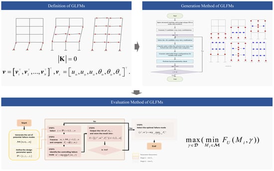
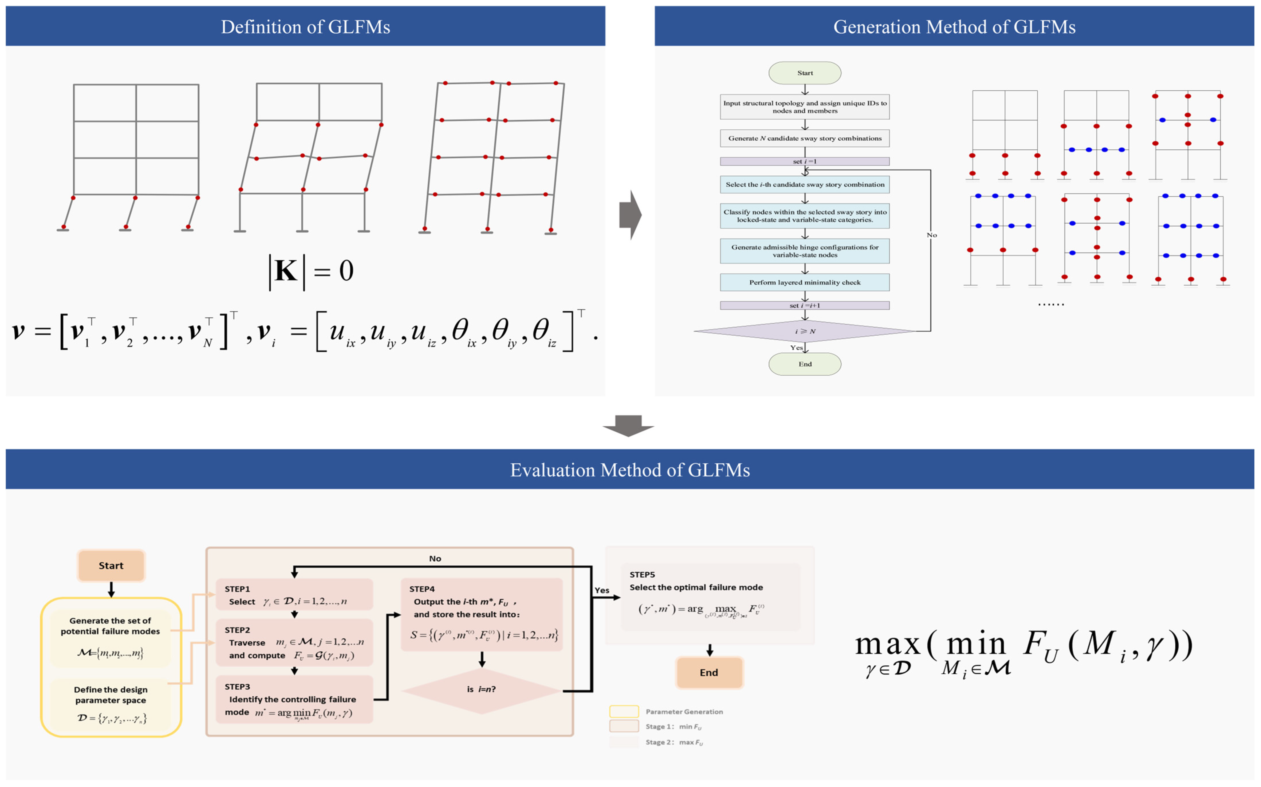
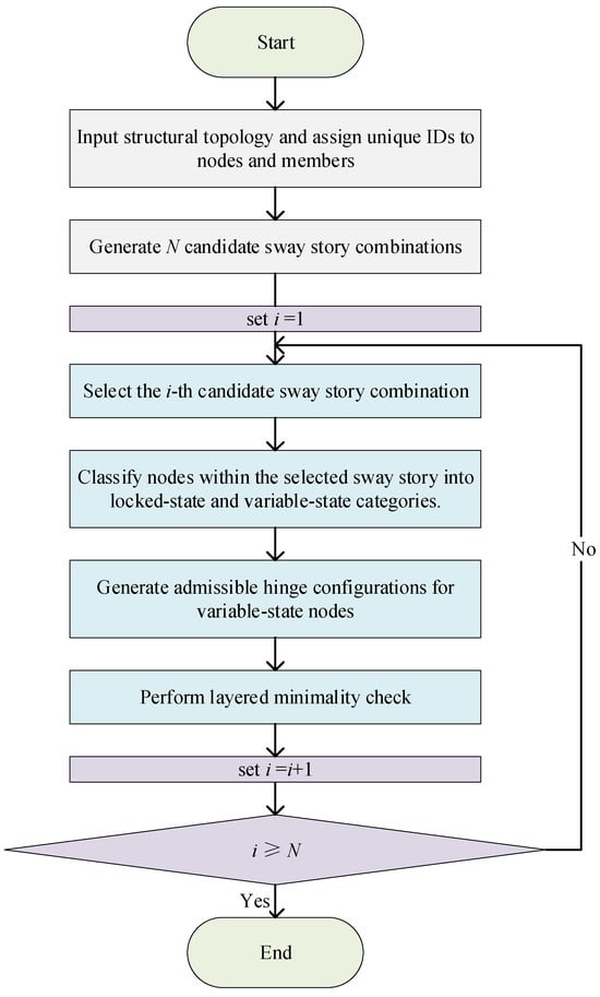
The remainder of this paper is organized as follows. Section 2 reviews related studies and introduces the definition of Generalized Lateral Failure Mechanism (GLFM). Section 3 presents the topology-based identification and generation methods. Section 4 describes the limit analysis-based two-stage evaluation procedure. Section 5 presents the case-study results and discusses the effects of topology and design constraints. Finally, Section 6 concludes the paper and outlines directions for future research. The overall framework of the proposed method is illustrated in Figure 1.
Figure 1.
Overall Framework.
2. Definition of Generalized Lateral Failure Mechanism (GLFMs)
2.1. Criteria of Structural Failure
At the structural level, the exceedance of limit states is not determined by the failure of any single element [16,17], as is often prescribed by current guidelines [18]. Reference [19] summarizes four widely used criteria of structural failure: (1) a weighted-average method for member damage [20], (2) statistical distributions of member performance [21,22], (3) cut-set theory (failure mechanism) [23], and (4) dynamic instability [24,25,26,27]. The first two criteria characterize failure primarily from a performance perspective; however, the selection of performance indicators and the calibration of corresponding thresholds are inherently subjective. This subjectivity limits their suitability as objective benchmarks for identifying structural failure. Cut-set theory defines failure as the condition in which the structure transforms into a kinematic mechanism. This approach provides a clear system-level interpretation of structural collapse and directly links failure to loss of load-carrying capacity. The dynamic instability evaluates failure through nonlinear dynamic analysis. Although this approach is physically rigorous, it typically requires extensive nonlinear time-history simulations and is computationally demanding. A comparison of the four structural failure criteria is provided in Table 1.
Table 1.
Comparison of structural failure criteria.
In this study, structural failure is defined as the formation of a kinematic mechanism (Criterion 3)—representing the ultimate state at which the global load-carrying capacity is attained [28].
2.2. Classification of Failure Mechanism
In frame structures, a failure mechanism can be represented by a distribution of plastic hinges that transforms the system into a kinematic mechanism. Given that hinges may form at various potential member cross-sections, the space of admissible mechanisms is theoretically unbounded. Existing classification schemes generally follow two lines: (1) combinatorial approaches, which construct complex mechanisms by combining fundamental mechanisms [29,30]; and (2) governing-action approaches, which classify failure according to the dominant physical response (e.g., flexural yielding, column deformation-limit, or shear failure) [23,31]. The primary goal of these traditional methods is to enumerate potential mechanisms under a given load pattern in order to determine ultimate capacity or quantify failure probability.
The present study adopts the second, governing-action classification but shifts the emphasis toward seismic design. Rather than exhaustive enumeration, our objective is to strategically identify a target failure mechanism that can serve as a predefined design target. Accordingly, this research targets mechanisms with the potential for optimal performance, thereby excluding those inherently non-optimal mechanisms.
2.3. Representative Failure Mechanisms Under Seismic Action
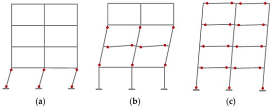
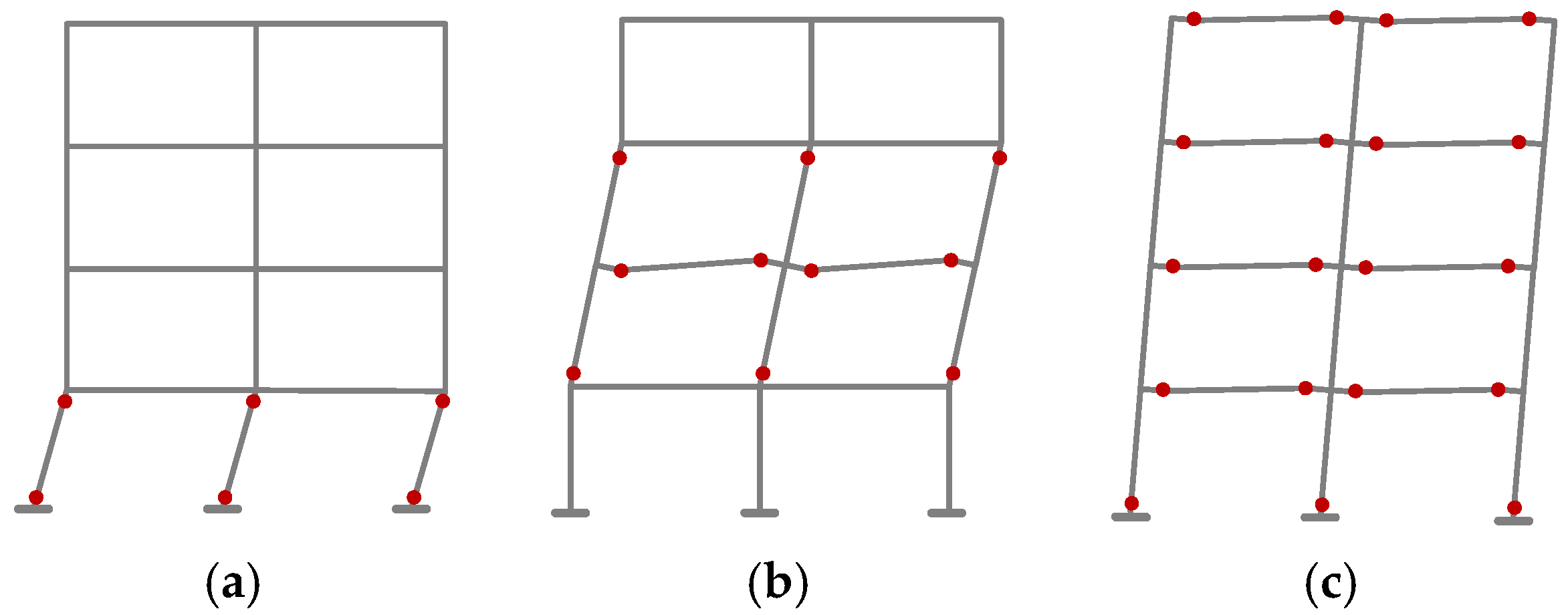
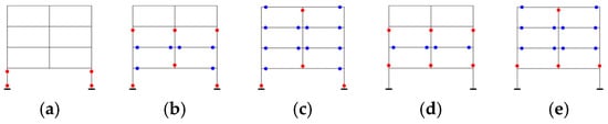
In multi-story frame structures with a clear story concept, earthquake-induced damage typically concentrates as lateral inter-story drift over one or more consecutive stories, leading to a lateral failure mechanism. As illustrated in Figure 2, these three plastic hinge distribution patterns can be broadly classified into three types: single-story, beam–column mixed, and global mechanisms.
Figure 2.
Lateral failure mechanisms under seismic action: (a) single-story, (b) beam–column mixed, and (c) global failures. The red dots denote the formation of plastic hinges at these locations.
However, existing studies on lateral failure mechanisms often approximate the entire failure space using only a handful of typical hinge patterns. For instance, the beam–column mixed mechanism is conventionally defined by a fixed template: hinges forming at the tops of all columns in the top story, at the bases of all columns in the bottom story, and at both ends of all beams in the intermediate stories. Such a distribution represents an idealized scenario that fails to account for the vast diversity of potential hinge combinations inherent in mixed mechanisms. Consequently, relying on these limited templates is insufficient to cover the entire failure domain.
2.4. Definition of GLFMs Based on Eigenvectors of the Stiffness Matrix
To determine whether a plastic hinge configuration constitutes a kinematic mechanism (or equivalently, a cut set), previous studies have typically adopted three identification approaches: (1) Plastic hinge count: The number of formed plastic hinges is greater than or equal to the degree of static indeterminacy plus one [32]. (2) Stiffness matrix: The structural stiffness matrix becomes singular, i.e., its determinant equals zero. (3) Joint rotation inspection: A lateral failure mechanism occurs when both ends of all columns in the sway story can rotate about their joints [33].
Critically, Criterion (1) is neither a necessary nor a sufficient condition for identifying specific lateral failure mechanisms. Criterion (2) is a necessary but insufficient condition: it confirms that a mechanism has formed, yet it cannot distinguish between different lateral failure patterns. Although Criterion (3) targets the kinematic essence of lateral failure, its practical implementation—involving “beam-removal” and layer-by-layer inspection—remains algorithmically cumbersome and lacks efficiency.
To improve the computational efficiency of identification, this study introduces the Generalized Lateral Failure Mechanism (GLFM), defined based on the null space of the structural stiffness matrix. This definition follows a fundamental kinematic principle: once a mechanism forms, the stiffness matrix becomes singular, and its null-space basis vectors directly describe the displacement field of the resulting mechanism.
Let K represent the stiffness matrix when the structure transforms into a mechanism. Assume is a basis vector in the null space of K. Organized by degrees of freedom, v and vi can be expressed as:
where vi denotes the six-degree-of-freedom (6-DOF) vector at node i. Its components uix, uiy, and uiz represent the translational displacements along the x, y, and z axes, respectively, while θix, θiy, and θiz represent the corresponding rotational components.
Through a comprehensive synthesis of structural response patterns, it is observed that the null-space basis vectors associated with failure mechanism possess several consistent and distinctive properties. These summarized characteristics are formulated as follows:
- (1)
- Degrees of freedom (DOFs) of nodes located in non-sway stories are approximately zero.
- (2)
- Nodes within a sway story sharing the same vertical coordinate exhibit identical values for each of their respective DOFs.
- (3)
- The mechanism is classified as translation-dominated lateral failure if the non-zero DOFs are limited to lateral directions, and as rotation-dominated lateral failure if they are limited to rotational directions. If the non-zero DOFs encompass both lateral and rotational directions, the mechanism is categorized as translation-rotation coupled lateral failure. Together, these three categories define the Generalized Lateral Failure Mechanisms (GLFMs).
Specifically, a ‘sway story’ is defined as stories whose movement causes the structure to transform into a lateral failure mechanism, and nodes within these stories are collectively denoted as the set . In contrast, a ‘non-sway story’ refers to a portion of the structure that remains kinematically stationary, with its nodes grouped into the set non-sway.
These characteristics are mathematically expressed as follows:
3. Generation Method of Generalized Lateral Failure Mechanisms (GLFMs)
Before introducing the specific searching and generating procedure, it is necessary to clarify the rationale for explicitly constructing the set of generalized lateral failure mechanisms (GLFMs).
Existing searching approaches for failure mechanisms are typically formulated under the assumption that the structural design is fixed. In such cases, the relative strength relationships among structural members are already determined, and the primary task is to identify which admissible failure mechanism governs the structural response. However, a key limitation is that there is currently no systematic method to comprehensively generate the full set of failure mechanisms for frame structures. Without an explicit generation procedure, certain admissible mechanisms may remain unidentified, leading to incomplete assessment. Therefore, prior to mechanism evaluation and design-space exploration, it is necessary to establish a systematic method for constructing the complete set of GLFMs that satisfy the kinematic criteria defined in Section 2.
It should be noted that the mechanisms considered in this study do not include undesirable failure patterns such as beam–column joint failure or column shear failure. Since the objective is to identify mechanism patterns for design, such brittle or non-ductile failure modes are intended to be avoided and are therefore excluded from the scope of the present mechanism search.
3.1. Enumeration-Based Search Method for GLFMs
Following the definition of GLFMs, an enumeration-based procedure is employed to identify all potential failure mechanisms, as detailed below: First, all candidate plastic-hinge locations are identified, from which N distinct hinge distributions are generated. For each distribution, the determinant of the corresponding stiffness matrix is evaluated. If the matrix is singular, the associated null-space basis vectors are extracted and verified against the GLFM kinematic criteria. Distributions that are consistent with these criteria are classified as valid GLFMs, while the others are discarded. By exhaustively screening all N distributions, the complete set of GLFMs for the structure is obtained.
Although theoretically feasible, exhaustive enumeration is computationally prohibitive. The combinatorial explosion of hinge distributions, coupled with the eigen-decomposition of high-dimensional stiffness matrices, imposes an exponential burden that renders the method impractical for complex engineering applications.
3.2. Concept of Minimal Cut Sets in Failure Mechanisms Analysis
Structural failure mechanisms can be expressed as cut sets, a concept originating from fault tree analysis in reliability theory. A cut set is a group of basic events that together cause the top event and is minimal if removing any event prevents the top event [34]. Focusing on minimal cut sets—rather than arbitrary cut sets—is essential because they eliminate redundant events and identify the most critical, irreducible paths to system failure, providing a concise basis for mechanism identification.
3.3. Node-State-Based Automatic Generation Algorithm for Minimal Cut Sets of GLFMs
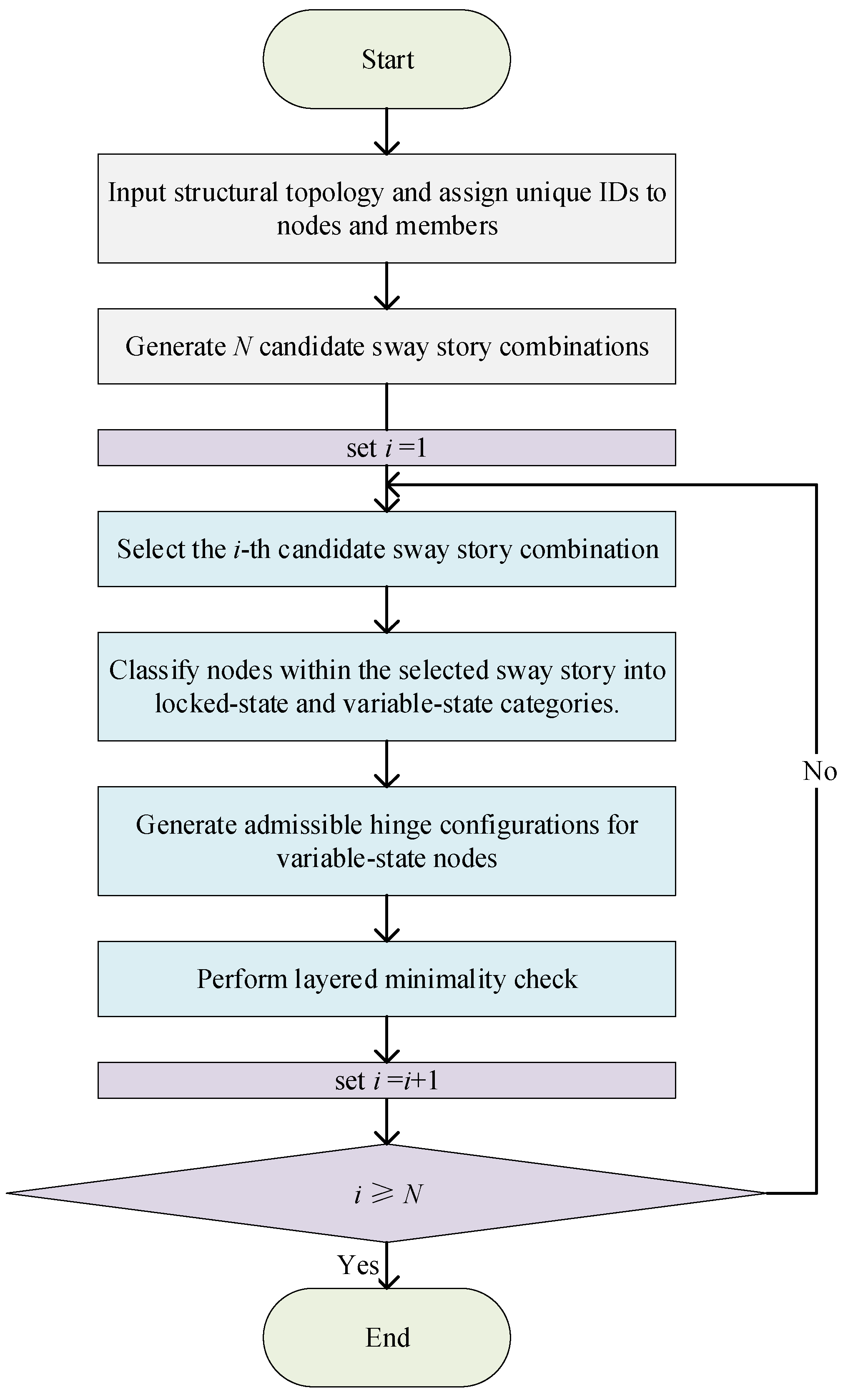
To identify the minimal cut sets of failure mechanisms for a given structural topology, this study proposes a node-state-based search algorithm. Unlike exhaustive enumeration, the proposed approach bypasses the costly evaluation of stiffness matrix determinants and eigenvectors. Instead, it inspects the plastic hinge states of members incident to each node, formulates identification criteria aligned with the GLFM definition, and systematically generates node combinations that satisfy these conditions. By shifting from matrix-level computation to topological state inspection, the algorithm mitigates the high-dimensional bottleneck as model size increases, substantially reduces computational complexity, and improves search efficiency (Figure 3).
Figure 3.
Flowchart of the node-state-based automatic generation algorithm for the minimal cut sets of failure mechanisms. Different colors are used to distinguish functional modules: green for terminals (Start/End), light blue for the core computational steps, and purple for loop control and decision-making logic.
The algorithm proceeds as follows:
- (1)
- Topology Initialization: The structural topology is first input, and unique identification numbers are assigned to all nodes and members. This step establishes a graph representation of the structure, where nodes correspond to joints and edges correspond to structural members.
- (2)
- Identification of Candidate Sway Stories:Let the structure consist of H stories.To capture all possible vertical segments that may potentially develop a sway mechanism, consecutive story combinations are systematically identified based on the total number of stories.For a given structure, each individual story and every possible consecutive multi-story segment are treated as a candidate sway story combination. These combinations define all admissible vertical regions within which a global or partial sway mechanism may form.For example, in a three-story frame structure, the candidate sway story combinations include:{1}, {2}, {3}, {1–2},{2–3}, {1–3}Each identified sway story combination defines a structural subregion to be further examined for kinematic admissibility and minimal cut-set formation.
- (3)
- Node Classification: Locked-State and Variable-State NodesFor each identified sway story combination, the nodes within the selected vertical segment are classified into two categories: locked-state nodes and variable-state nodes. This classification plays a fundamental role in both the mechanical admissibility and the computational efficiency of the search process.To develop a valid sway failure mechanism within a given story segment, certain hinge conditions must necessarily be satisfied. In particular, for any sway story to undergo relative lateral displacement and form a kinematic mechanism, plastic hinges must form at the column bases located at the bottom boundary of the segment. Without hinge formation at these bottom column bases, the segment remains rotationally restrained and cannot constitute a sway mechanism.Nodes at which such hinge formation is structurally mandatory are defined as locked-state nodes. Their hinge states are fixed in advance and are not treated as variables during the combinatorial search. These nodes represent indispensable boundary conditions derived from mechanism compatibility requirements.
- (4)
- Generation of Admissible Hinge Configurations: All nodes within the selected sway story that are not classified as locked-state nodes are designated as variable-state nodes. The hinge configurations at these nodes are not predetermined; instead, they are allowed to vary within a restricted admissible state space defined by structural compatibility constraints. By traversing the admissible states of variable-state nodes while keeping locked-state nodes fixed, the algorithm systematically constructs all kinematically admissible candidate mechanisms. The admissible states of variable-state nodes are determined. To satisfy the construction requirements, namely (a) that all columns within the sway story are rotatable and (b) that the resulting sets qualify as minimum cut sets, each variable-state node is restricted to two admissible states:
- All beam ends connected to the node form plastic hinges.
- All column ends connected to the node form plastic hinges.
By traversing and combining the state space of all variable-state nodes, the algorithm systematically generates the complete set of candidate minimal cut sets of failure mechanisms for the current sway story.
- (5)
- Layered Minimality Verification: To ensure the minimality condition, a real-time layered verification is integrated into the search process. While generating candidate cut sets for a sway story, the algorithm concurrently scans all consecutive story subsets. If any subset is identified where all variable-state nodes reach the ‘all column ends hinged’ state, it is flagged as an independent mechanism. Such non-conforming candidates are immediately discarded, guaranteeing that only true minimal cut sets are retained in the final output.
- (6)
- Iterative Examination of All Sway Story Combinations: After the minimality verification is completed for the current sway story, the index is updated as i = i + 1. The algorithm then checks whether all candidate sway story combinations have been examined.
- (7)
- Final Output: Upon completion of the iterative process, the algorithm outputs the complete set of minimal cut sets corresponding to all admissible sway failure mechanisms of the structure.
4. Evaluation Method of Generalized Lateral Failure Mechanism (GLFMs)
4.1. General Concept
The capacity design method integrates mechanism control principles into seismic practice [35], where the foundational step is the selection of a kinematically admissible plastic mechanism—conceptually equivalent to the ‘failure mechanism’ defined in this study. Conventionally, an ideal mechanism for frame structures is presumed to be the global beam-sway mechanism, characterized by plastic hinges forming at the bases of first-story columns and the ends of all beams. This conventional paradigm is predicated on the assumption that columns should be protected as critical members while beams act as primary energy-dissipating elements to ensure structural ductility. Nevertheless, the optimality of this predefined mechanism is often assumed rather than demonstrated.
To address this issue, a nested optimization method is introduced to evaluate seismic failure mechanisms. This method incorporates the generating algorithm described in Section 3 to systematically explore the space of failure mechanism. The specific procedure is structured as follows:
(1) Inner Layer: Controlling Mechanism Identification. For a given set of design parameters, the controlling mechanism is determined using the upper-bound theorem of limit analysis. This step identifies the unique mechanism that results in the minimum ultimate load among all kinematically admissible GLFMs.
(2) Outer Layer: Parametric Optimization. By systematically varying the design parameters within a feasible design space, the method seeks the optimal parameter configuration that maximizes this minimum ultimate load. The failure mechanism corresponding to this max–min point is defined as the global optimum, as it represents the highest structural capacity attainable under the prescribed load pattern and design constraints.
4.2. Limit Analysis and the Upper-Bound Theorem
The upper-bound theorem of limit analysis is a fundamental principle in plasticity theory for estimating the ultimate load-bearing capacity of structures [36,37,38,39]. It states that, among all kinematically admissible failure mechanisms, the governing failure mechanism corresponds to the minimum load factor, α, at which internal dissipation equals external work. This method does not require consideration of loading paths or deformation processes, and thus offers theoretical rigor and computational efficiency.
4.3. Internal-External Work Balance Equation
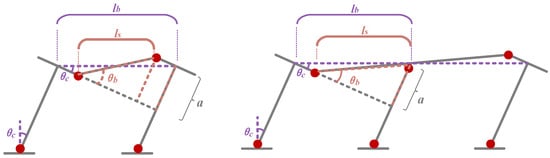
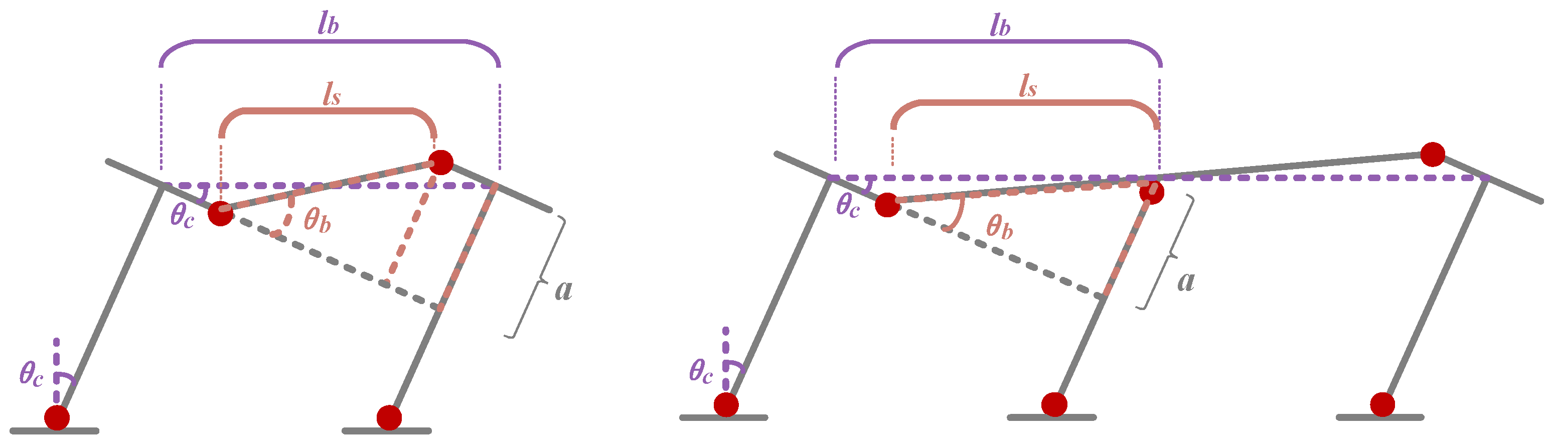
As shown in Figure 4, the kinematic relationship between beam-end and column-end rotations [32] is controlled by the spatial distribution of plastic hinges and the specific failure mechanism. This relationship is formulated as:
where denotes the rotations of the beam-end and column-end plastic hinges, respectively; represents the beam span; and signifies the effective length associated with the beam rotation.
Figure 4.
Relationship between column and beam rotations.
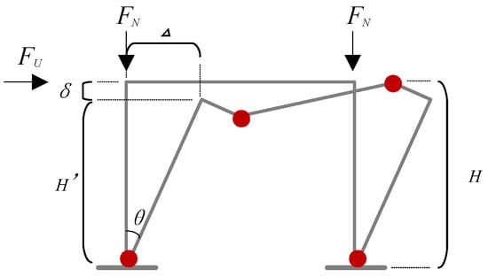
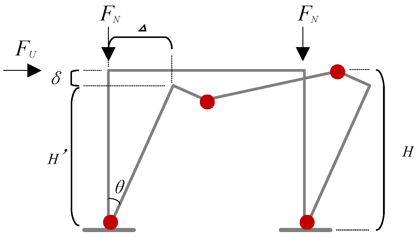
Figure 5 presents the external loads applied to the frame structure and the associated virtual displacements. When calculating the external virtual work, the P–Δ effect induced by vertical loads must be incorporated for high-rise frames, and the contribution of vertical loads under vertical virtual displacements must be accounted for. Conversely, for low-rise structures, the influence of the vertical load FN is typically negligible. Accordingly, the relationship between the story height and vertical virtual displacements, is defined as:
where H denotes the story height, θ represents the column-end rotation; δ signify the virtual displacement associated with vertical loads.
Figure 5.
External loads and corresponding virtual displacements. The red dots denote the formation of plastic hinges at these locations.
When the contribution of vertical loads is neglected, the ultimate load-carrying capacity for each failure mechanism becomes independent of the magnitude of the assumed virtual displacements and is calculated as:
where and denote the numbers of plastic hinges in columns and beams, respectively, for a given failure mechanism; represents the number of stories participating in the mechanism; and signify the flexural strengths of the i-th plastic hinge in columns and beams, respectively; and α is the load factor that satisfies the internal–external work balance; Δ signifies the horizontal virtual displacement.
4.4. Relative Yield Strength Coefficient and Design Space
The upper-bound theorem is effective for evaluating the failure state corresponding to a given design configuration, in which the relative strength relationships among structural members are already determined. However, the objective of the present study differs fundamentally. Rather than determining the governing mechanism for a single predefined design, this work seeks to explore a constrained design space characterized by adjustable relative strength relationships among members. For each admissible design configuration, the governing failure mechanism must first be identified, and the associated structural capacity must then be evaluated. Consequently, the problem addressed herein is not merely mechanism identification under fixed parameters, but a design-oriented optimization problem that requires a comprehensive and systematic representation of all geometrically admissible failure mechanisms.
Accordingly, the relative yield strength relationships among members are defined through a set of story-level coefficients, and the corresponding design space is subsequently constructed.
4.4.1. Definition of the Story-Level Relative Yield Strength Coefficient
This study introduces the story-level relative yield strength coefficient (γ). For each story i, γi is defined as the ratio of the sum of the flexural yield strengths of all column ends to the sum of the flexural yield strengths of all beam ends along the direction of analysis. For an n-story frame structure, the coefficients of all stories are sequenced to form a relative yield strength coefficient vector, .
4.4.2. Construction of the Design Space
The design space is defined as the feasible set of story-level relative yield strength coefficient vectors (γ) that satisfy the design constraints and can be expressed as follows:
where n denotes the dimensionality of the story-level relative yield strength coefficient vector; N represents the total number of samples generated in the design space.
Constructing the design space requires clarification of the following components:
- (1)
- Initial Design Parameters: An initial set of design parameters must be specified before constructing the design space and defining constraints. In frame structures, the flexural yield strengths of beams are initially determined based on the distribution of vertical loads. Subsequently, the flexural yield strengths of the columns ends are assigned based on the results of a standardized design conducted in accordance with relevant seismic codes.
Based on these beam and column capacities, the initial relative yield strength coefficient vector, γ(0), is established to serve as the benchmark for the subsequent optimization process. Furthermore, a scalar coefficient γ(0) is defined to represent the overall strength intensity of the initial design, calculated as the arithmetic mean of the components within the vector γ(0), is defined as follows:
where γ(0) denotes the initial average relative yield strength coefficient of the structure; n represents the total number of stories and i denotes the story index, ranging from 1 to n.
- (2)
- Constraints: The design space is constrained based on three fundamental principles: comparability (ensures economic consistency among different design parameters), feasibility (imposes an upper bound to γmax), and rationality (imposes a lower bound γmin).
4.5. Evaluation Procedure
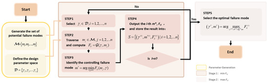
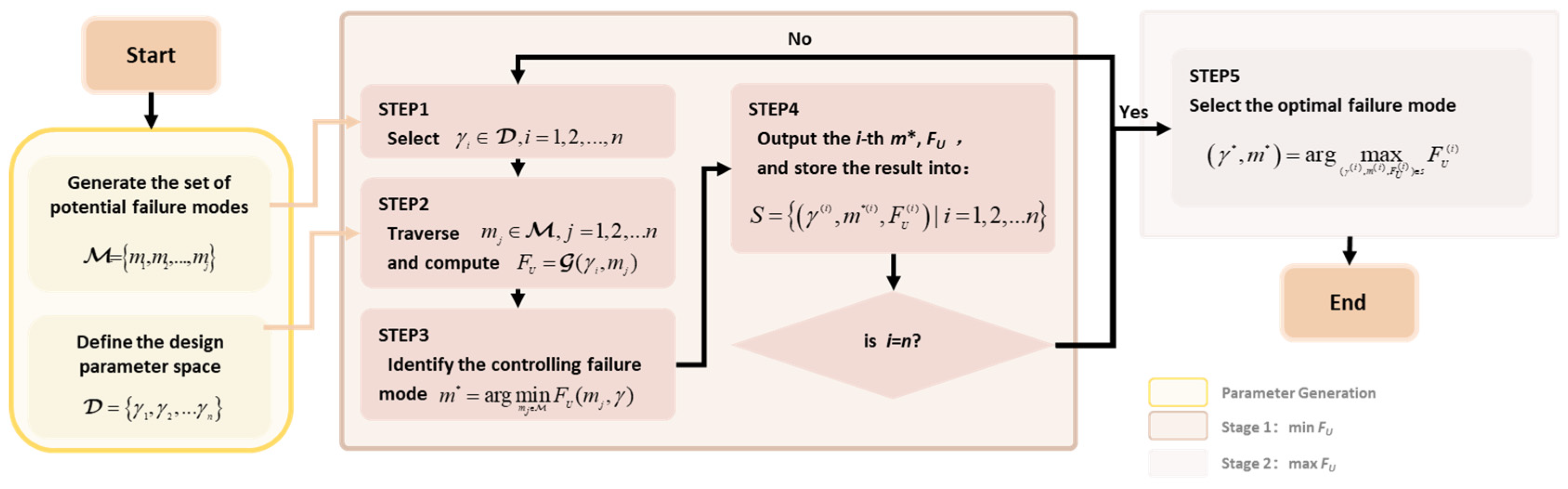
To operationalize the nested optimization framework proposed in Section 4.1, this section details the quantitative evaluation procedure (Figure 6).
Figure 6.
Flowchart of the two-stage evaluation procedure.
Stage 1 (min-FU):
The governing failure mechanism corresponding to each design parameter vector γ(i) within the design space D is determined. Specifically, for the i-th global relative yield strength coefficient vector γ(i) from the design space, the set of potential failure mechanisms is explored, and the ultimate load capacity for each failure mechanism is calculated as follows:
Among the considered failure mechanisms, the one with the minimum ultimate load capacity is identified as the governing failure mechanism, expressed as
Each analysis result is recorded as a triplet:
All analysis results are then compiled into the following collection:
Stage 2 (max-FU):
The optimal combination of failure mechanism and parameter vector is selected from the collection of governing failure mechanisms:
This combination corresponds to the failure mechanism evaluation result under the specified design constraints. This selected mechanism is subsequently designated as the target failure mechanism.
5. Case Studies and Analysis
5.1. Structural Topologies and Design Constraints
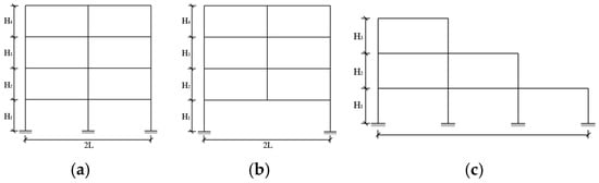
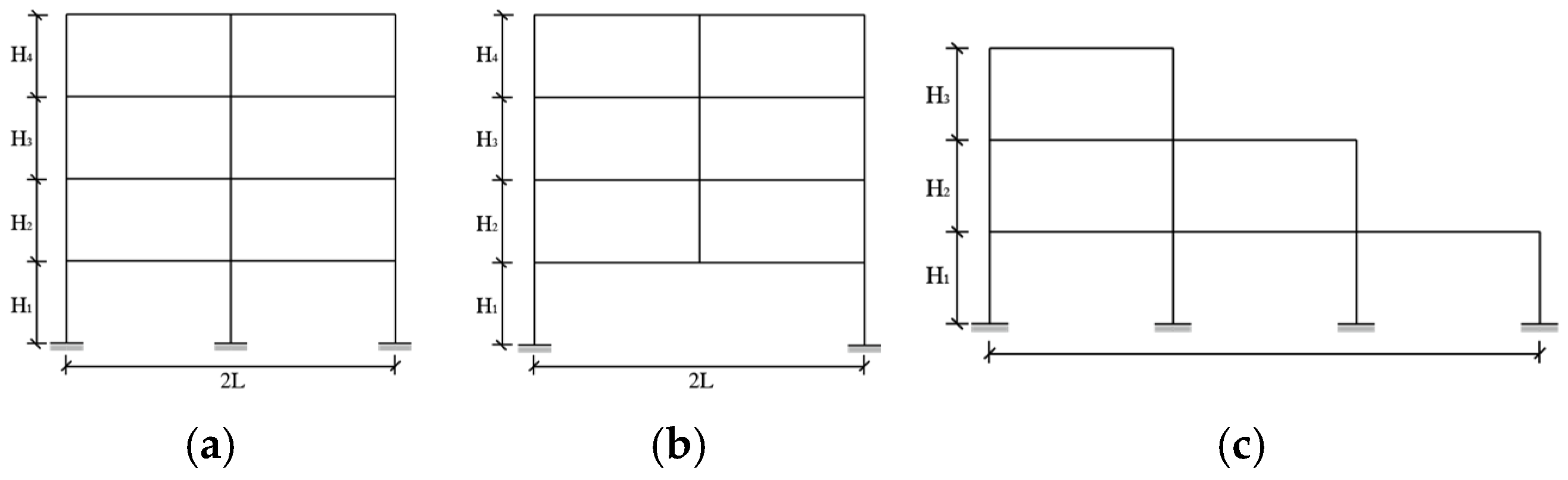
Three frame structures were considered as research objects in this study: a regular frame (Figure 7a), a transfer-beam frame (Figure 7b), and a step-back frame (Figure 7c). The regular and transfer-beam frames represent typical structural configurations, whereas the step-back frame introduces vertical irregularity and is adopted to evaluate the applicability and robustness of the proposed mechanism-oriented framework under non-regular conditions. For each structure, the minimal cut sets of GLFMs were identified and quantitatively evaluated. The case studies were conducted under a triangular lateral load distribution pattern. Based on these results, the effects of parameters such as story height and constraint conditions on the target failure mechanism were further examined.
Figure 7.
Structural topologies of the three frame types: (a) Regular frame (M-rg), (b) Transfer-beam frame (M-trs), (c) Step-back frame (M-irg).
5.2. Generation of Candidate Failure Mechanisms
By employing the search algorithm detailed in Section 3, the minimal cut sets of failure mechanisms were identified and generated for M-rg, M-trs, and M-irg with the results summarized in Table 2.
Table 2.
Number of minimal cut sets for each failure mechanism. (‘/’ denotes ‘not applicable’ as the M-irg structure consists of only three stories).
5.3. Design Space
5.3.1. Flexural Yield Strength of Beam
In frame structures, the reinforcement design and flexural yield strength of beams are primarily controlled by vertical load. Consequently, the beam capacities in this study were first determined to serve as a baseline for the analysis. To highlight the relative strength relationship between beams and columns, the flexural yield strengths of the beams were normalized. For the regular and step-back frames, the vertical load on the beams of each story was equivalent to a normalized value of 1.0, and the yield strengths were established accordingly. In contrast, for the transfer-beam frame, the beams at the transfer level were assigned a load of 2.0 to account for the significantly higher structural demands typical of such systems, while all other stories maintained a load of 1.0.
5.3.2. Design Constraints
To limit the design space dimensions while ensuring the rationality of the design schemes, three constraints were introduced:
(1) Total column yield strength (Csum)
The total column yield strength must remain equal to the initial value (Equation (17)) to ensure consistent material consumption across all design schemes.
where is the number of potential plastic hinge sections at column ends on the j-th story; represents the total flexural yield capacity of all beams on the j-th story; is the story-level relative yield strength coefficient on the j-th story in the i-th design scheme and is the total number of stories.
(2) Interstory strength difference control (Sdiff)
The strength difference between any two adjacent stories must not exceed 35% (Equation (18)).
where Si and Si+1 represent the sums of the yield strengths of the column members on the i-th and (i + 1)-th stories, respectively.
(3) Upper and lower bounds (γmin, γmax)
The relative yield strength coefficients are limited γmin = 0.2, and γmax = 5.0.
5.4. Evaluation Results
Table 3, Table 4 and Table 5 present the evaluation results for 36 design scenarios across three structural topologies. In these tables, “Sample size” indicates the number of feasible samples that satisfy the design constraints. “γ*” represents the set of design parameter that results in the target failure mechanism. “CombID” denotes the identifier of the target failure mechanism, expressed as “sway story—sequence number”. “Model ID” denotes as “M–type–j–k,” where type, j, and k represent the topology (regular, transfer-beam, step-back), story height variation scheme, and γ(0), respectively. The “Story height distributions” are represented by the vector , where each element hj denotes the height of the j-th story from the ground up.
5.4.1. Regular Frame Structures
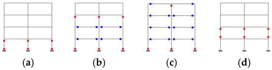
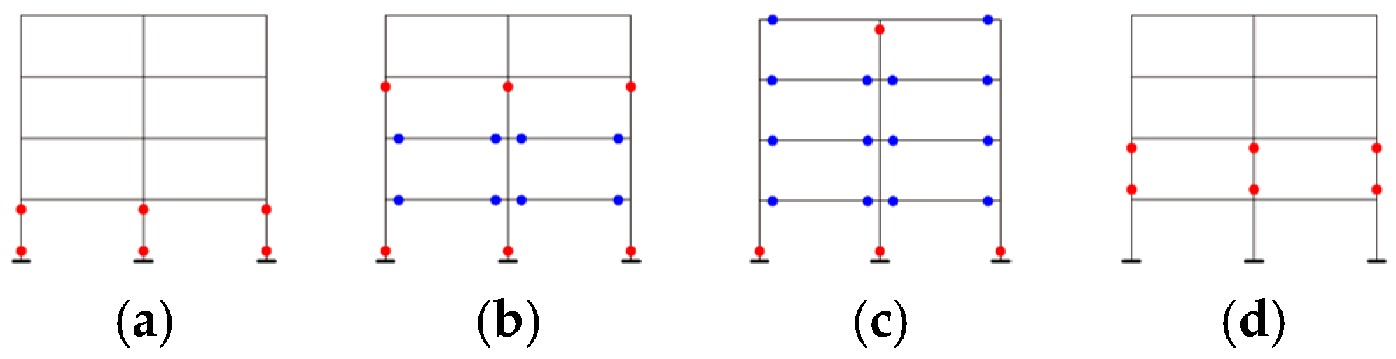
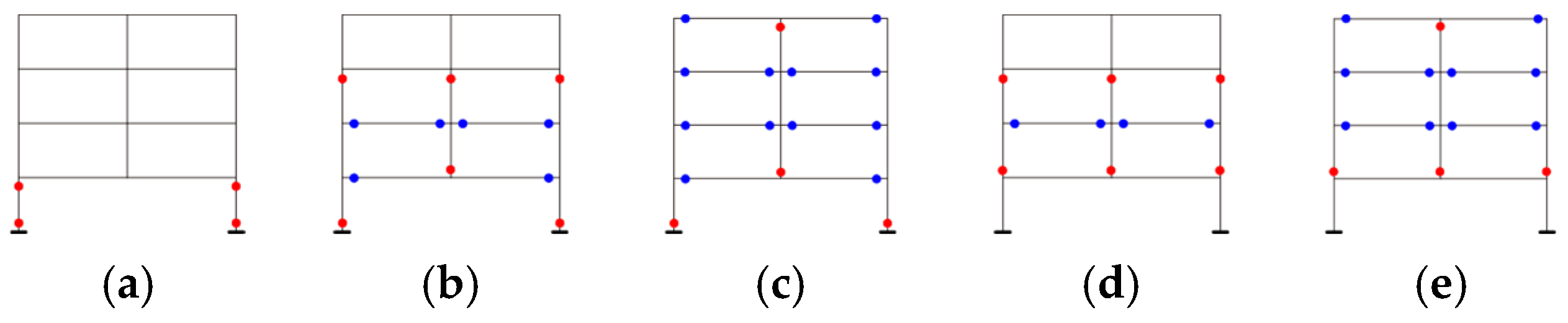
A total of twelve regular frame cases were investigated, and the results are presented in Table 3 and Figure 8. Across these scenarios, 4 distinct failure mechanisms were identified. As indicated in Table 3, at a low strength level of γ(0) = 0.4, the target failure mechanisms are characterized by localized mechanisms, such as a single-story mechanism ([1]–1, [2]-1). As γ(0) increases, the target failure mechanism evolves into multiple-story mechanisms. At γ(0) = 2.8, the target failure mechanism spans all stories ([1,2,3,4]–1536) representing a global failure mechanism.
Figure 8.
Target failure mechanisms of regular frame structures: (a) [1]-1, (b) [1,2,3]-32, (c) [1,2,3,4]-1536, (d) [2]-1. Blue dots denote the plastic hinges in the beams, and red dots represent the plastic hinges in the columns.
Table 3.
Failure mechanism evaluation results for regular frame structures.
This evolutionary pattern is primarily attributed to the governing influence of γ(0) on the total column yield strength constraint Csum (Equation (17)). When γ(0) is small, Csum is correspondingly low, indicating that the column flexural yield strength is weaker than the beam yield strength. Consequently, during the first stage of failure mechanism evaluation (min-FU), mechanisms with a higher proportion of column-end hinges are more likely to be selected from the candidate minimal cut sets. With gradually increasing Csum, the relative strength of the columns becomes substantially greater than that of the beams, making beam-dominated mechanisms more likely to emerge as the controlling failure mechanisms with the lowest load capacity in the first-stage evaluation.
5.4.2. Transfer-Beam Frame Structures
A total of twelve transfer-beam frame cases were investigated, with the evaluation results summarized in Table 4 and Figure 9. Across these scenarios, 5 distinct target failure mechanisms were identified. While the general trend aligns with that of regular frames—where the target failure mechanism transitions from localized single-story to global mechanisms as γ(0) increases.
Figure 9.
Target failure mechanisms of transfer-beam frame structures: (a) [1]-1, (b) [1,2,3]-30, (c) [1,2,3,4]-1534, (d) [2,3]-4, (e) [2,3,4]-192. Blue dots denote the plastic hinges in the beams, and red dots represent the plastic hinges in the columns.
Table 4.
Failure mechanism evaluation results for transfer-beam frame structures.
Owing to the significantly enhanced strength of the first-story transfer beam, no mechanism characterized by full beam hinging at the first story was selected as the target mechanism. The increased flexural capacity of the transfer beam effectively suppresses the formation of a beam-dominated collapse mechanism at that level. As a result, the mechanism selection differs from that of regular frames.
5.4.3. Step-Back Frame Structures
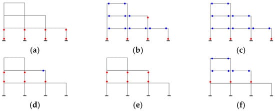
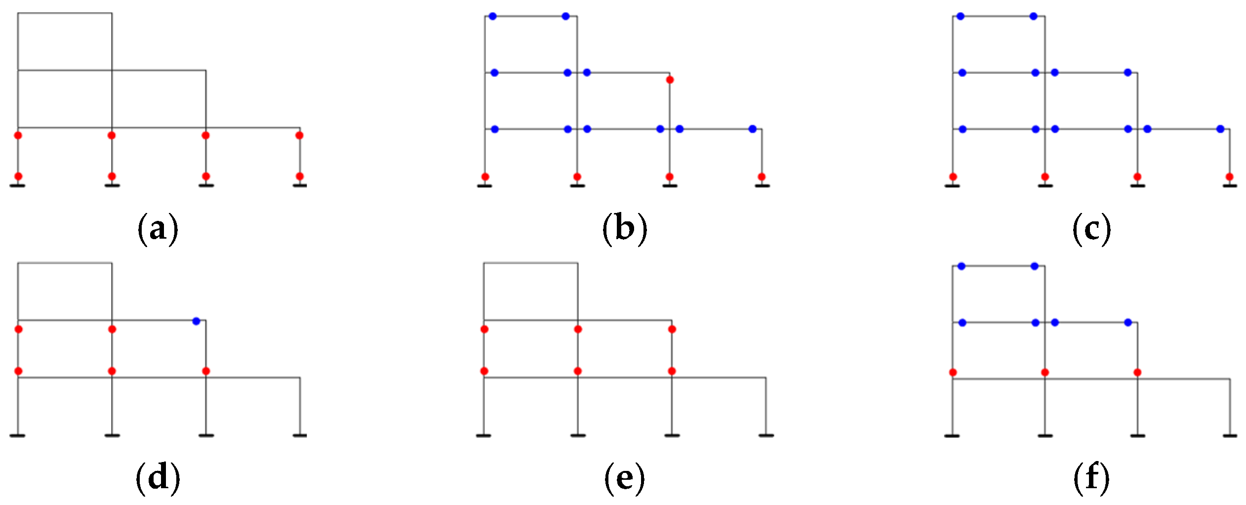
A total of twelve step-back frame cases were investigated, with the evaluation results summarized in Table 5 and Figure 10. Across these scenarios, 6 distinct target failure mechanisms were identified, indicating a pronounced sensitivity of mechanism selection to variations in structural parameters.
Figure 10.
Target failure mechanisms of step-back frame structures: (a) [1]-1, (b) [1,2,3]-412, (c) [1,2,3]-420, (d) [2]-1, (e) [2]-2, (f) [2,3]-28. Blue dots denote the plastic hinges in the beams, and red dots represent the plastic hinges in the columns.
Table 5.
Failure mechanism evaluation results for step-back frame structures.
Characterized by vertically irregular configurations, step-back frames exhibit target failure mechanism patterns that differ fundamentally from those observed in regular and transfer-beam frames. In contrast to the regular and transfer-beam cases, a systematic progression toward global collapse mechanisms is not always observed as γ(0) increases. Nevertheless, a consistent tendency can still be identified: with increasing γ(0), the target mechanisms generally involve a decreasing proportion of column hinges.
The influence of story-height distribution is particularly evident in M-irg-3, where the mid-story height significantly exceeds that of the adjacent stories. In this case, the target failure mechanism involves only the top two stories rather than the entire frame. Under equivalent lateral displacement conditions, the increased height of the middle story reduces the rotation demand of its columns, resulting in smaller plastic rotations and lower internal work contributions. Consequently, this partial mechanism is therefore more likely to be selected as the target mechanism.
5.5. Numerical Validation of the Proposed Framework
This section presents a numerical validation of the failure mechanisms and corresponding load-carrying capacities obtained in Section 5.4 by comparing them with nonlinear pushover results from OpenSeesPy (v3.7.0.3). Representative cases of the regular frame with γ(0) = 2.5 are selected to compare the load-carrying capacities associated with different failure mechanisms against the corresponding nonlinear simulation results, thereby illustrating the consistency between the proposed evaluation framework and the actual structural response.
2D finite element models were established in OpenSeesPy (v3.7.0.3). Beam and column members were modeled using force-based beam-column elements (forceBeamColumn) with fiber-section discretization to capture sectional nonlinear behavior. Concrete and reinforcing steel within the sections are simulated using nonlinear constitutive models, where the Concrete02 material model is adopted for concrete and the Steel02 material model is used for reinforcing steel.
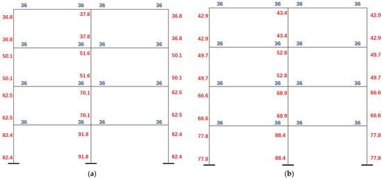
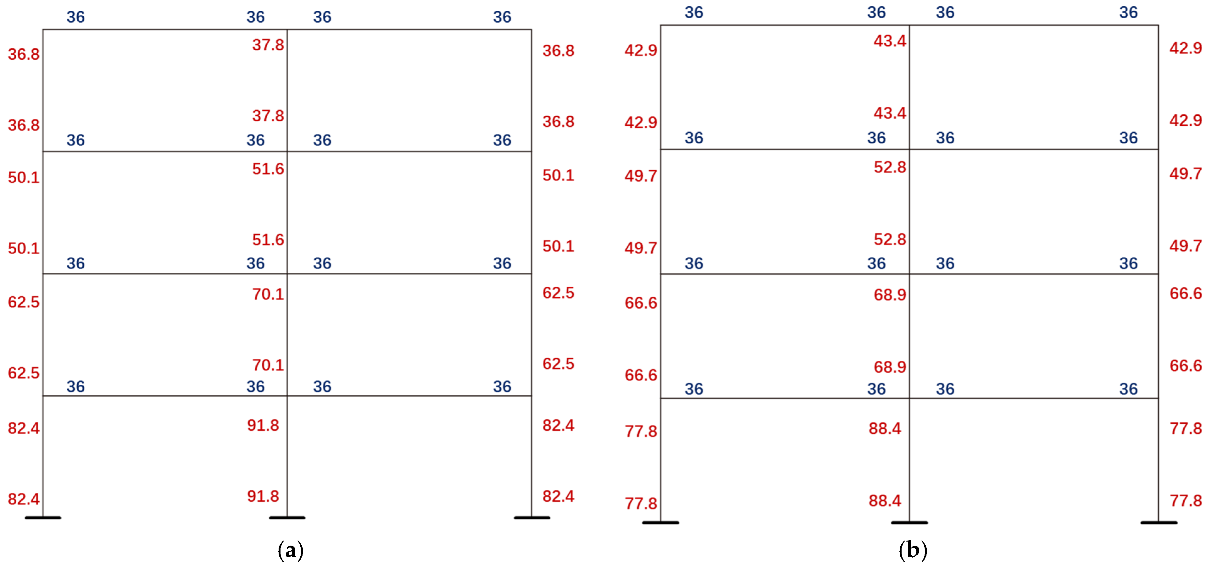
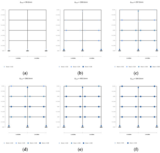
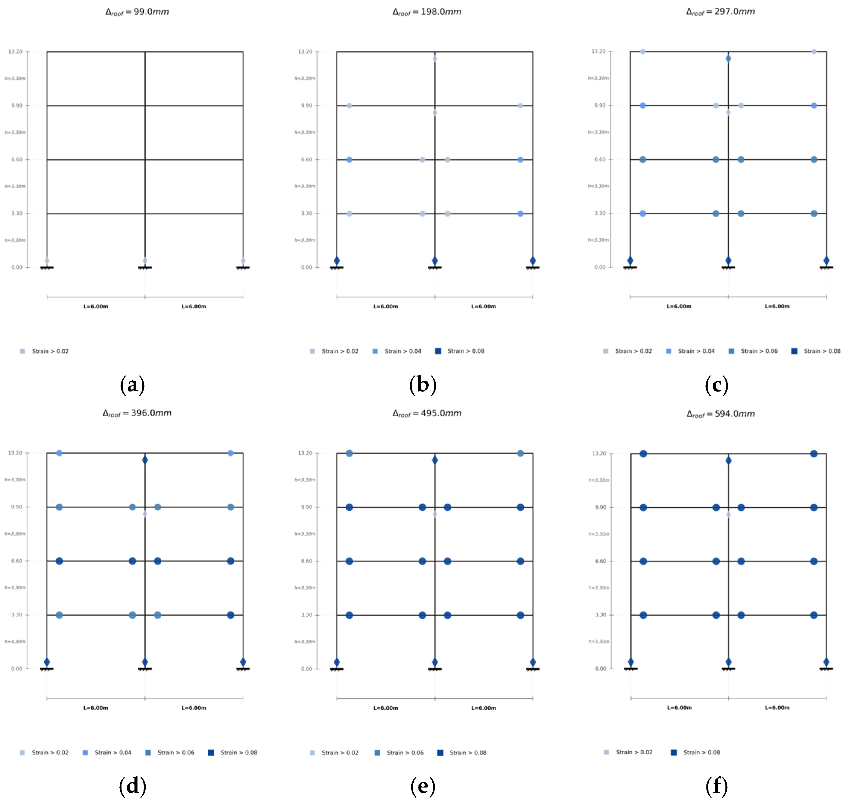
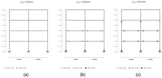
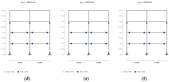
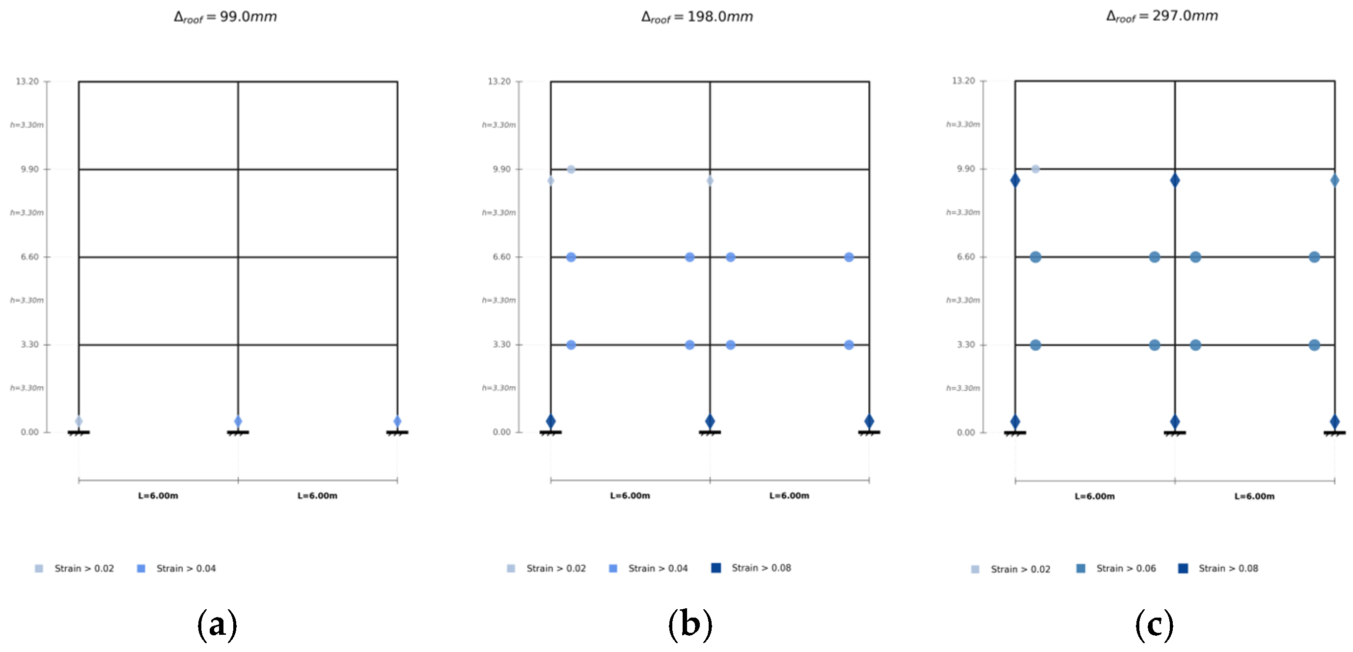
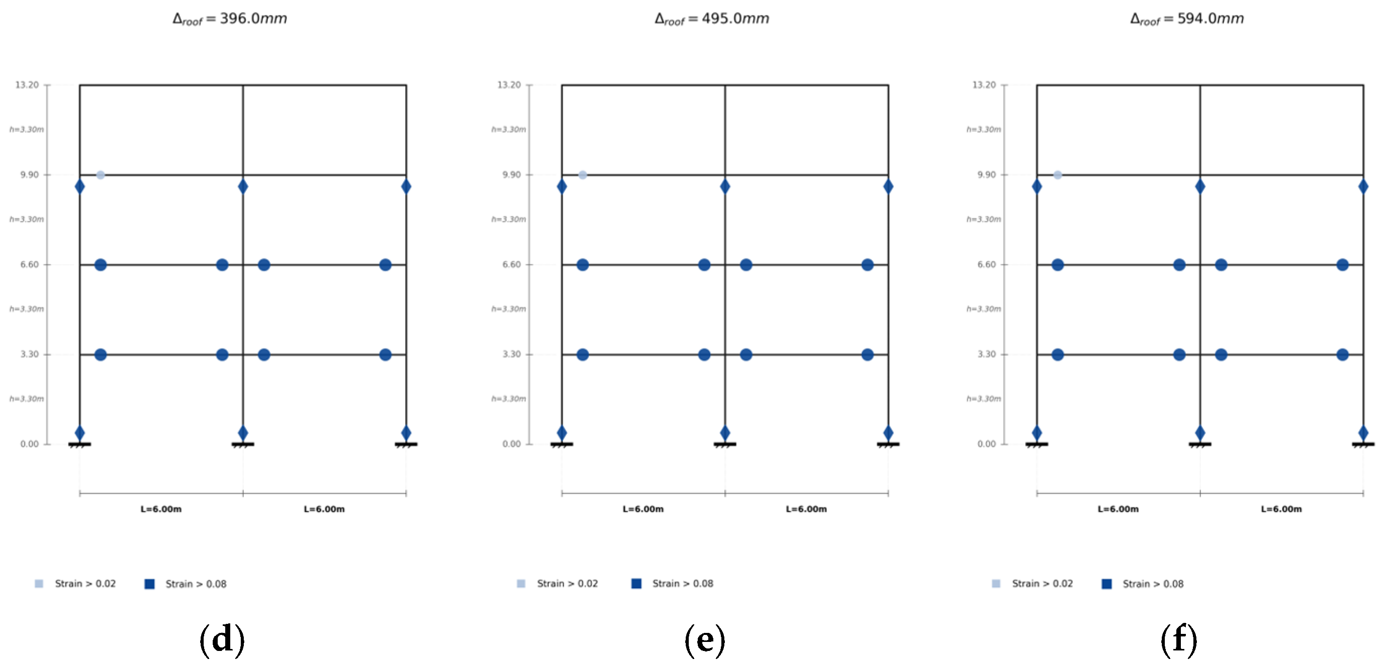
The geometric and material properties are listed in Table 6. Two distinct failure mechanisms, [1,2,3,4]-1536 (Figure 8c) and [1,2,3]-32 (Figure 8b), were designed based on different γ vectors and are hereafter referred to as models M-V-1 and M-V-2, respectively. The corresponding flexural yield moments at both ends of each member are illustrated in Figure 11. A triangular lateral load pattern was adopted to conduct pushover analysis, and the progressive development of plastic hinges for the two cases is shown in Figure 12 and Figure 13. In the figures, the formation of a plastic hinge at a member end is identified when the reinforcement strain reaches the yield strain.
Table 6.
Geometric and Material Properties.
Figure 11.
Flexural yield moments at member ends of the validation models: (a) M-V-1; (b) M-V-2. Red-colored numbers indicate the plastic bending moments at the ends of columns, and blue-colored numbers denote the plastic bending moments at the ends of beams.
Figure 12.
Evolution of the failure mechanism of model M-V-1 during pushover analysis: (a) Δroof = 99 mm, (b) Δroof = 198 mm, (c) Δroof = 297 mm, (d) Δroof = 396 mm, (e) Δroof = 495 mm, (f) Δroof = 594 mm. The diamond symbols represent column hinges, and the circular symbols represent beam hinges.
Figure 13.
Evolution of the failure mechanism of model M-V-2 during pushover analysis: (a) Δroof = 99 mm, (b) Δroof = 198 mm, (c) Δroof = 297 mm, (d) Δroof = 396 mm, (e) Δroof = 495 mm, (f) Δroof = 594 mm. The diamond symbols represent column hinges, and the circular symbols represent beam hinges.
The predicted ultimate load-carrying capacities obtained from the proposed evaluation method are compared with the nonlinear numerical results from OpenSeesPy in Table 7. The relative differences are within 3.6%, demonstrating good agreement and validating the accuracy of the proposed approach.
Table 7.
Comparison of ultimate load-carrying capacities obtained from the proposed method and pushover analysis.
6. Conclusions
In this study, we proposed a general framework for determining a target failure mechanism in frame structures. The concept and mathematical definition of GLFMs were introduced. Generation method of GLFMs was developed. Furthermore, an evaluation method for GLFMs was formulated. A total of 36 case studies covering three representative structural topologies were systematically investigated. The main conclusions are summarized as follows:
(1) The target failure mechanism is identified through a two-stage limit-analysis-based evaluation. For a given set of design parameters, the upper-bound theorem is used to determine the governing collapse mode as the mechanism with the minimum ultimate load-carrying capacity. Subsequently, within the design space constructed under rational constraints, different admissible design parameter combinations are generated and evaluated. A max–min criterion is then applied to select the mechanism whose minimum collapse capacity is maximized, and this mechanism is defined as the target failure mechanism.
(2) Application of the proposed framework to regular, transfer-beam, and step-back frame structures identified 15 distinct target failure mechanisms among the 36 cases. The results demonstrate that the target failure mechanism is not necessarily the traditionally assumed global collapse mechanism. Instead, it is governed by the interaction between structural topology, strength distribution, and design constraints.
(3) For regular and transfer-beam frame structures, a systematic transition from localized single-story mechanisms to global multi-story mechanisms is observed as γ(0) increases. In contrast, step-back frames characterized by vertical irregularity do not always exhibit a systematic progression toward global collapse mechanisms with increasing γ(0). Nevertheless, with increasing γ(0), the target mechanisms generally involve a decreasing proportion of column hinges.
(4) Numerical validation through nonlinear pushover analysis confirms the accuracy and mechanical consistency of the proposed framework. For the representative regular-frame cases, the ultimate load-carrying capacities obtained from the proposed method agree well with OpenSeesPy simulation results, with relative differences within 3.6%. Notably, model M-V-1, which was designed with the selected target failure mechanism as the design objective, exhibits a higher ultimate load-carrying capacity than model M-V-2, confirming the validity of the target failure mechanism selection.
Despite the theoretical contributions and case study validations presented herein, certain limitations should be acknowledged. First, the proposed framework is developed within the scope of static limit analysis, and its applicability under dynamic nonlinear analysis has not yet been verified. Second, the identification of target failure mechanisms in the cases relies on the assumption of a triangular lateral load distribution, and its generality under alternative loading scenarios remains unexplored. Third, the influence of masonry infill walls is not considered in the present study, and its potential effect on failure mechanism remains to be examined.
Future research may proceed in four primary directions. First, although the present study focuses on planar frame structures for clarity and systematic comparison, the proposed definition, search strategy, and evaluation procedure of GLFMs are not inherently restricted to two-dimensional systems. Further research is therefore needed to systematically extend and validate the proposed approach for complex 3D structural systems and real-world engineering applications. Second, the applicability of the proposed framework should be extended beyond frame structures to encompass more diverse structural systems, such as braced frames and frame–shear wall structures. Third, more efficient strategies for constructing the design space can be introduced to further improve computational efficiency. Fourth, failure mechanism evaluation should be integrated with mechanism control and system-level structural reliability analysis to enhance the theoretical framework for structural safety.
Overall, the proposed method for generating and evaluating GLFMs highlights the limitations of experience-based failure mechanism selection in practical applications. It reveals intrinsic relationships among structural topology, design constraints, story-height variation, and the target failure mechanism. This method offers both theoretical support and an analytical tool for implementing failure-mechanism-based seismic design across diverse frame topologies.
Author Contributions
Conceptualization, C.X.; methodology, Y.W. and C.X.; validation, Y.W.; formal analysis, Y.W.; investigation, Y.W.; resources, C.X.; data curation, Y.W.; writing—original draft preparation, Y.W.; writing—review and editing, C.X.; visualization, Y.W.; supervision, C.X.; project administration, C.X.; funding acquisition, C.X. All authors have read and agreed to the published version of the manuscript.
Funding
This research was funded by the Youth Research Fund of China Academy of Building Research grant number 20210118331030002 and The National Key Research and Development Program of China grant number 2023YFC3805005.
Data Availability Statement
The original contributions presented in this study are included in the article. Further inquiries can be directed to the corresponding author.
Conflicts of Interest
The authors declare no conflicts of interest.
References
- Xiao, C.-Z.; Li, J.-H.; Chen, C.-H.; Ren, C.-C.; Lu, Y.; Kang, Z. Performance based seismic design method of predetermined yield mode for complicated building structures. J. Build. Struct. 2019, 40, 92–99. [Google Scholar] [CrossRef]
- Ye, L.-P.; Jin, X.-L.; Tian, Y.; Lu, X.; Miao, Z.; Qu, Z.; Lin, X.; Lu, X. “System capacity design method” for the seismic design of building structures: A review. Eng. Mech. 2022, 39, 1–12. [Google Scholar] [CrossRef]
- Yang, T.-Y.; Tung, D.-P.; Li, Y.-J. Equivalent Energy Design Procedure for Earthquake Resilient Fused Structures. Earthq. Spectra 2017, 34, 795–815. [Google Scholar] [CrossRef] [Scilit]
- Zhai, Z.-P.; Guo, W.; Li, Y.-Z.; Yu, Z.; Cao, H.; Bu, D. An improved performance-based plastic design method for seismic resilient fused high-rise buildings. Eng. Struct. 2019, 199, 109650. [Google Scholar] [CrossRef] [Scilit]
- Shoeibi, S.; Gholhaki, M.; Kafi, M.-A. Simplified force-based seismic design procedure for linked column frame system. Soil Dyn. Earthq. Eng. 2019, 121, 87–101. [Google Scholar] [CrossRef] [Scilit]
- Shoeibi, S.; Kafi, M.-A.; Gholhaki, M. New performance-based seismic design method for structures with structural fuse system. Eng. Struct. 2016, 132, 745–760. [Google Scholar] [CrossRef] [Scilit]
- Goel, S.-C.; Liao, W.-C.; Bayat, M.-R.; Chao, S.-H. Performance-based plastic design (PBPD) method for earthquake-resistant structures: An overview. Struct. Des. Tall Spec. Build. 2009, 19, 115–137. [Google Scholar] [CrossRef] [Scilit]
- Mazzolani, F.-M.; Piluso, V. Plastic design of seismic resistant steel frames. Earthq. Eng. Struct. Dyn. 1997, 26, 167–191. [Google Scholar] [CrossRef] [Scilit]
- Montuori, R.; Troisi, M.; Piluso, V. Theory of Plastic Mechanism Control of Seismic-Resistant MR-Frames with Set-Backs. Open Constr. Build. Technol. J. 2012, 6, 404–413. [Google Scholar] [CrossRef] [Scilit]
- Noruzvand, M.; Mohebbi, M.; Shakeri, K. Performance-based seismic design of low-rise steel moment-resisting frames targeting collapse fragility curve. Structures 2024, 70, 107630. [Google Scholar] [CrossRef] [Scilit]
- Monjardin-Quevedo, G.; Salazar, R.; Tolentino, D.; Gaxiola-Camacho, O.D.; Vazquez-Becerra, G.E.; Gaxiola-Camacho, J.R. Seismic reliability of steel SMFs with deep columns based on PBSD philosophy. Structures 2022, 42, 1–15. [Google Scholar] [CrossRef] [Scilit]
- Mastrandrea, L.; Piluso, V. Plastic design of eccentrically braced frames, II: Failure mode control. J. Constr. Steel Res. 2009, 65, 1015–1028. [Google Scholar] [CrossRef] [Scilit]
- Sepahvand, M.-F.; Akhrawat, L. Seismic design of steel moment-resisting knee-braced frame system by failure mode control. Earthq. Eng. Struct. Dyn. 2025, 54, 271–294. [Google Scholar] [CrossRef] [Scilit]
- Liao, W.C.; Goel, S.C. Performance-based plastic design and energy-based evaluation of seismic resistant RC moment frame. J. Mar. Sci. Technol. 2012, 20, 9. [Google Scholar] [CrossRef] [Scilit]
- Bai, J.; Yang, T.Y.; Ou, J. Improved performance-based plastic design for RC moment resisting frames: Development and a comparative case study. Int. J. Struct. Stab. Dyn. 2018, 18, 1850050. [Google Scholar] [CrossRef] [Scilit]
- Ruggieri, S.; Chatzidaki, A.; Vamvatsikos, D.; Uva, G. Reduced-order models for the seismic assessment of plan-irregular low-rise frame buildings. Earthq. Eng. Struct. Dyn. 2022, 51, 3327–3346. [Google Scholar] [CrossRef] [Scilit]
- Ruggieri, S.; Uva, G.; Vamvatsikos, D.; Porco, F. Two frugal options to assess class fragility and seismic safety for low-rise reinforced concrete school buildings in Southern Italy. Bull. Earthq. Eng. 2021, 19, 1415–1439. [Google Scholar] [CrossRef] [Scilit]
- EN 1998-3:2005; Eurocode 8: Design of Structures for Earthquake Resistance—Part 3: Assessment and Retrofitting of Buildings. European Committee for Standardisation: Brussels, Belgium, 2004.
- Liu, L. Seismic Collapse Risk Evaluation and Control Methodology for Split-Foundation RC Frames. Ph.D. Thesis, Chongqing University, Chongqing, China, 2021. [Google Scholar]
- DiPasquale, E.; Ju, J.-W.; Askar, A.; Çakmak, A.S. Relation between global damage indices and local stiffness degradation. J. Struct. Eng. 1990, 116, 1440–1456. [Google Scholar] [CrossRef] [Scilit]
- Qiao, S.-F. Research on Seismic Fragility and Bracing Configuration of RC Frame Structure Using Component-Performance-Based Methodology. Ph.D. Thesis, South China University of Technology, Guangzhou, China, 2018. [Google Scholar]
- Galanis Panagiotis, H.; Moehle, J. Development of collapse indicators for risk assessment of older-type reinforced concrete buildings. Earthq. Spectra 2015, 31, 1991–2006. [Google Scholar] [CrossRef] [Scilit]
- Jalayer, F.; Franchin, P.; Pinto, P.-E. A scalar damage measure for seismic reliability analysis of RC frames. Earthq. Eng. Struct. Dyn. 2007, 36, 2059–2079. [Google Scholar] [CrossRef] [Scilit]
- Federal Emergency Management Agency. Recommended Seismic Design Criteria for New Steel Moment-Frame Buildings; Report No. FEMA-350, SAC Joint Venture; Federal Emergency Management Agency: Washington, DC, USA, 2000. [Google Scholar]
- Bai, J.-L.; Ou, J.-P. Optimization of failure modes for reinforced concrete buildings based on IDA method. Eng. Mech. 2011, 28, 198–203. [Google Scholar]
- Ding, L.-C.; Chen, J.-B. Physically-based collapse failure criteria in progressive collapse analyses of random-parameter multi-story RC structures subjected to column removal scenarios. Eng. Struct. 2024, 325, 119379. [Google Scholar] [CrossRef] [Scilit]
- Ding, L.-C.; Chen, J.-B.; Caspeele, R. Dynamic sensitive failure mode in the progressive collapse of RC structures subjected to column removal scenarios. Eng. Struct. 2024, 323, 119301. [Google Scholar] [CrossRef] [Scilit]
- GB 50068-2018; Unified Standard for Reliability Design of Building Structures. China Building Industry Press: Beijing, China, 2018.
- Neal, B.-G.; Southworth, P. The rapid calculation of the plastic collapse load for a framed structure. Proc. Inst. Civ. Eng. 1952, 1, 58–71. [Google Scholar] [CrossRef] [Scilit]
- Greco, A.; Cannizzaro, F.; Pluchino, A. Automatic evaluation of plastic collapse conditions for planar frames with vertical irregularities. Eng. Comput. 2019, 35, 57–73. [Google Scholar] [CrossRef] [Scilit]
- Yu, X.-H.; Lv, D.-G.; Zheng, H.-Q. Probabilistic evaluation of column overdesign factor through reliability analysis for typical failure modes. J. Build. Struct. 2014, 35, 169–176. [Google Scholar] [CrossRef]
- Li, H.; Wu, S.-W.; Lv, T.-R. Automatic generation of frame mechanisms and system reliability. J. Hohai Univ. 1992, 20, 104–110. [Google Scholar]
- Gu, X.-L.; Sun, F.-F. Computer-Aided Simulation of Concrete Structures; Tongji University Press: Shanghai, China, 2002. [Google Scholar]
- Freudenthal, A.-M.; Garretts, J.-M.; Shinozuka, M. The Analysis of Structural Safety. J. Struct. Div. 1966, 92, 267–326. [Google Scholar] [CrossRef] [Scilit]
- Paulay, T.; Priestley, M.-J.-N. Seismic Design of Reinforced Concrete and Masonry Buildings; Wiley: New York, NY, USA, 1992. [Google Scholar]
- Boothby, T.-E.; Brown, C.-B. A general lower and upper bound theorem of static stability. Eng. Struct. 1993, 15, 189–196. [Google Scholar] [CrossRef] [Scilit]
- Drucker, D.-C.; Greenberg, H.-J.; Prager, W. The Safety Factor of an Elastic-Plastic Body in Plane Strain. J. Appl. Mech. 1951, 18, 371–378. [Google Scholar] [CrossRef] [Scilit]
- Drucker, D.-C.; Prager, W.; Greenberg, H.-J. Extended limit design theorems for continuous media. Q. Appl. Math. 1952, 9, 381–389. [Google Scholar] [CrossRef] [Scilit]
- Wang, Y.-L.; Zhao, M.; Hao, J.-P.; Xue, Q.; Jiang, W. Seismic analysis of steel-concrete composite frame structures based on the ultimate balance theory. Eng. Mech. 2022, 39, 81–88. [Google Scholar] [CrossRef] [Scilit]

Disclaimer/Publisher’s Note: The statements, opinions and data contained in all publications are solely those of the individual author(s) and contributor(s) and not of MDPI and/or the editor(s). MDPI and/or the editor(s) disclaim responsibility for any injury to people or property resulting from any ideas, methods, instructions or products referred to in the content. |
© 2026 by the authors. Licensee MDPI, Basel, Switzerland. This article is an open access article distributed under the terms and conditions of the Creative Commons Attribution (CC BY) license.