


Abstract
The building sector is responsible for a significant share of global greenhouse gas emissions, raw material usage, and waste generation, driving the need for new circular design strategies. Among these, Design for Disassembly (DfD) promotes the reuse, repair, and recycling of building components. However, existing quantitative DfD assessment methodologies generally require extensive preliminary studies, which limit their practical use. This article presents a new quantitative DfD assessment methodology developed within the EU-funded INFINITE project, which aims to provide designers with a simple yet robust tool to evaluate the detachability potential of building integrated systems without requiring prior environmental studies. This methodology has been designed to evaluate specific DfD scores for maintenance, reuse, and recycling, using the mass and lifespan of products or systems as weighting factors. The tool was tested and validated on several systems developed during the INFINITE project. In the specific case of the Building Integrated Solar Thermal (BIST) system, it successfully identified key design improvements—such as enhanced accessibility for maintenance operations and optimized component connections. Industrial partners reported high usability and recognized the tool as a valuable decision-support instrument during early development phases. Nevertheless, the assessment methodology also revealed some limitations related to the assessment of the specific components and end-of-life scenarios, and to the absence of a holistic evaluation of trade-offs between mass-based score and environmental impacts.
1. Introduction
The building sector accounts for 42% of the European Union’s annual energy consumption and 35% of annual greenhouse gas (GHG) emissions according to the European Environment Agency (EEA) [1]. Moreover, this sector is responsible for 30% of raw material usage and 25% of water consumption and it also accounts for over 25% of all European Union (EU) waste [2]. In many cases, the construction phase (materials + building process) can represent up to 50% of the building’s life cycle carbon footprint, especially for highly efficient or nearly zero-energy buildings where operational emissions are reduced [3]. This observation has driven the development of new methods for designing more sustainable buildings [4]. Among the strategies explored, enhancing the detachability of buildings and their components is widely recognized as an effective means of increasing building circularity, and thus overall sustainability [5,6,7,8]. This approach is commonly referred to as Design for Disassembly (DfD).
The concept of DfD was initially popularized by the manufacturing industry in the early 1990s with the increasing environmental concerns, which led to the integration of the life cycle aspect into the product’s design [9]. The DfD in the Architecture, Engineering and Construction (AEC) field is defined by ISO 20887:2020 [10] as an “approach to the design of a product or constructed asset […] that facilitates disassembly […] at the end of its useful life, in such a way that enables components […] and parts to be reused, recycled, recovered for energy or, in some other way, diverted from the waste stream”.
1.1. The H2020 INFINITE Project
INFINITE is a European funded project under the H2020 framework that aims to develop the off-site prefabrication of multifunctional systems integrated into facade elements for the deep renovation of residential buildings. One of the INFINITE project’s objectives was to develop an easy-to-use DfD assessment methodology to help system manufacturers improve the circularity of their systems by providing a DfD score for three different scenarios: maintenance, reuse, and recycling. The DfD assessment methodology developed in the INFINITE framework is the subject of this article.
1.2. Literature Review
DfD has attracted a growing interest since the mid-2010s. This trend has been highlighted by Ostapska et al. who identified seven DfD-related scientific publications released in 2015 versus 40 in 2021 [11]. This phenomenon has also been reported by Attia et al. who identified 5 publications on the disassembly potential of buildings in 2015 versus 13 in 2021 and 26 in 2023 [12]. In parallel with the growing interest in DfD principles, several assessment methodologies have been developed to evaluate the disassembly potential of building systems and components. These methodologies are intended to support designers in improving the repairability, reusability, and recyclability of products and building elements, thereby facilitating the integration of circularity considerations early in the design process.
DfD assessment methods can be classified into two categories as follows:
- Qualitative methods: particularly suitable for detachability assessments during the first design phases, when the project is not sufficiently mature to have detailed data. Qualitative methodology generally describes the studied system or building using diagrams that facilitate identification for system/building DfD areas of improvement [13,14,15].
- Quantitative assessment methods: when the system or building design is sufficiently mature to have a precise idea of component types and connections, quantitative assessment methods can offer meaningful improvements in disassembly potential evaluations for systems or buildings. Quantitative assessment methodologies were first developed in the manufacturing sector and then gained interest in the construction field [15,16,17]. The common basis for this type of method is to attribute numerical values to detachability-related parameters at different building/system levels (material, component, element, system, connections…) [15,18]. Some of the numerical values used in quantitative assessment methods originate from directly measurable metrics, such as Life Cycle Assessment (LCA) [5,6] or percentage of the reusable mass [12,19,20], while others are based on expert-judged scores, aiming to quantitatively assess certain qualitative disassembly criteria, such as the connection type and accessibility [15,17,21,22,23].
Certain methodologies employ directly measurable metrics as weighting factors for expert-judged scores. This enables the gathering of both types of quantitative assessment and a consideration of a more complete range of DfD criteria [17,24].
Although quantitative methodologies require a larger amount of information as input compared to qualitative methodologies, having a quantified disassembly score reduces subjective bias and facilitate comparison between system versions or concurrent systems as there is a common comparison base.
In the AEC field, Alba Concepts, in collaboration with the Dutch Green Building Council (DGBC) and W/E Adviseurs (Utrecht, The Netherlands), has developed a “Disassembly Potential Measurement Method” to quantitatively assess the “disassembly potential” of a building [17]. The “disassembly potential” was first introduced by Mike van Vliet [25]—one of the co-authors of the “Disassembly Potential Measurement Method 2.0” [17]—and was used as the basis of this methodology. This quantitative DfD assessment methodology is based on four key parameters: connection type, connection accessibility, connection independency, and geometry of product edge [17]. Each parameter is assigned a score ranging from 0.1 to 1, with 1 representing the highest level of detachability, using and adapting the Elma Durmisevic evaluation system [15]. Disassembly potential scores of every component combined with their corresponding Environmental Cost Indicator (ECI) as a weighting factor enabled us to calculate the disassembly potential at the building scale, taking into account the environmental impact of each component [15,17]. This disassembly potential assessment methodology offers designers an effective way to evaluate the disassembly potential of a building by quantitatively comparing different versions and visualize areas of improvement.
The DRIVE-0 EU-funded project developed a DfD assessment tool that takes up the work of Alba Concepts to evaluate the disassembly potential of elements and building as a whole, both for maintenance and end-of-life design concerns [26]. The DRIVE-0 tool proposes a color-coding system to simplify results analyses of the detachability score and thus helps designers gain a better understanding of the results [18]. However, Patrick Daly highlighted the limitation of the number of DfD indicators considered and the absence of weighting factors as areas for improvement in future assessment methodologies [18].
Verberne [24] developed a methodology that determines circularity indicators for material, product, system, and building scales by gathering and adapting previous works on building circularity assessments, in particular, works from the Ellen MacArthur Foundation and Granta Design [27], Elma Durmisevic [15], and Stewart Brand [14]. Verberne’s approach is a holistic circularity assessment methodology that evaluates the circularity at the material, product, system, and building scales. Verberne’s indicators are therefore convenient for a holistic circularity assessment that is particularly suitable for detailed study.
In parallel with DfD-specific assessment methodologies, broader sustainability and circularity frameworks have been developed to support building design across multiple performance dimensions. The Circular Buildings Toolkit developed by Arup [28] builds upon established frameworks, such as LEVEL(s), and certification systems including DGNB, adopting a system-level perspective to integrate circular economy principles through strategies and design actions related to material efficiency, adaptability, longevity, and resource recovery. Within this holistic framework, Design for Disassembly is explicitly identified as one of several circular design strategies; however, the toolkit primarily relies on qualitative or semi-quantitative guidance aimed at early design alignment with sustainability benchmarks and does not provide a quantitative, component-, or connection-level assessment of disassembly performance or enable a direct comparison between alternative system configurations. Complementary to such design-oriented frameworks, Eurac Research supports circular construction through the Circular Lab [29] and the Design Assessment service [30], within which an end-of-life assessment tool [31] has been developed to quantitatively evaluate dismantling performance based on real disassembly practices or theoretical data. The assessment is conducted across system, element, component, and material levels and is informed by parameters such as connection type and accessibility, providing a quantitative evaluation of reuse, recycling, and recovery potentials at the end-of-life stage of building products. Regarding damage evaluation, Eurac Research [32] extends the work of Elma Durmisevic [32,33] by distinguishing two indicators, based on damage intensity and damage area, as both can hinder the reuse potential of the product and should be evaluated separately. While this approach offers a robust, practice-based representation of dismantling outcomes, its focus on post-use scenarios distinguishes it from DfD methodologies intended to support design-stage decision-making through a predictive assessment of the disassembly potential.
1.3. Purpose of the Methodology
The purpose of the DfD assessment tool developed as part of the EU-funded INFINITE project was to offer to renovation facade kits designers a simple and intuitive tool for assessing detachability, following on from the DRIVE 0 project [18,26]. The enrichment of the previous approaches comes from the use of specific weighting factors to prioritize elements that have the greatest environmental impact while, at the same time, avoiding using factors that require prior study, such as ECI used in the Alba Concepts method [17]. In this sense, the ambition of the INFINITE DfD assessment tool is twofold: to increase the awareness of the importance of the DfD approach at the early design phase, which is particularly relevant in view of emerging policy and regulatory frameworks, such as the European Circular Economy Action Plan [34], which are expected to progressively require the integration of circular design principles in building practices; and to provide designers a decision-making aid that considers different disassembly situations and component configurations using only input data directly available during the design phase.
The DfD assessment methodology developed in this study aims to achieve the aforementioned objectives by assessing detachability for the reuse, repair, and recycle circularity levels of Cramer [35], integrating two parameters as weighting factors:
- The mass of the elements, to promote the reduction in non-reusable waste at the end of life of the elements, or buildings.
- The expected lifespan of the system components.
The selection of mass and expected lifespan as weighting factors reflects a deliberate trade-off between methodological simplicity and analytical precision. These parameters were chosen because they are directly available during early design stages and are commonly used proxies in environmental and maintenance-related assessments.
2. Materials and Methods
2.1. DfD Assessment Methodology Presentation
The DfD quantitative assessment methodology developed as part of the INFINITE project is a simplified tool used to evaluate and improve detachability of the different solutions proposed, considering three different disassembling uses: maintenance, reuse, and recycling. Separating the disassembly uses allows us to apply adapted criteria to assess the performance and, in the meantime, calculate a global DfD score that considers each specific use.
Although the tool was used to assess disassembly potential for the kits developed in the frame of the INFINITE project, the methodology is also suitable for other systems that compose a building.
2.2. Weighting Factors
As mentioned before, two weighting factors were chosen for the DfD assessment methodology. The chosen weighting factors had to not require prior studies to be able to use the methodology for early stages of maturity systems. It also needed to avoid the use of function-dependent parameters as the systems studies as part of this project had completely different functionalities.
Considering those constraints, the mass of the system and elements was chosen for reuse and recycle scenarios as it is directly linked to end-of-life burdens, correlated with embodied environmental impact at a material level. In addition, mass is easy to measure and to interpret for any material, component, element, or system.
The weighting factor selected for the maintenance scenario was the expected lifespan of the system and of the elements composing it. This factor is, to some extent, open to interpretation; nonetheless, it was chosen because lifespan directly correlates with maintenance frequency, which is the key parameter to optimize alongside ease of maintenance, the latter already being addressed through the detachability scores.
These two parameters were selected as they are the most relevant factors at the early design stage, while assessing a building product/system even thinking on future deepened analysis. Mass is a fundamental input in environmental impact assessments, as the life cycle assessment quantifies impacts based on mass-based material flows multiplied by characterization factors [10], while lifespan plays an important role to determine the avoided impacts due to the extended life concept.
2.3. Terminology
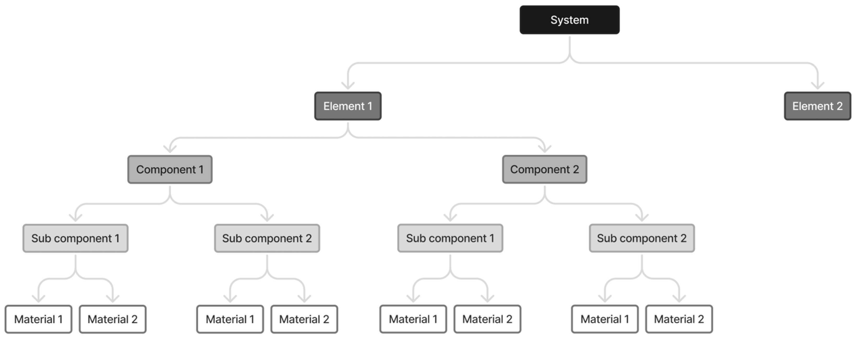
The constitutive levels of the system are defined and structured in accordance with ISO 20887:2020 [10], and are broken down into the following hierarchical levels:
- Material (M) refers to the most basic level of a product once it has been dismantled, representing raw or processed materials that can be directly reused or, at a minimum, serve as feedstock for recycling processes.
- Subcomponent (S) refers to a functional part of a component that cannot be meaningfully separated further without losing its function, such as glazing units, gaskets, or control elements. Subcomponents may consist of one or more materials shaped to fulfil a specific function.
- Component (C) is a more complex item than the subcomponent and it can be composed of several materials shaped to meet a specific sub-function. For example, a cable is composed of a metal conductive material and a plastic insulating envelope and responds to a data transfer sub-function. A component can be made of materials and subcomponents.
- Elements (E) is an assembly of multiple components forming a major construction part, such as panelized facade elements, wall assemblies, or floor systems, often designed to comply with dimensional or modular standards.
- System (Sy) is an assembly of elements, components, subcomponents, and/or materials that together form a functional unit, such as an entire building or a distinct building subsystem (e.g., facade modules or heating systems).
During manufacturing and assembly, material transformation processes happen in such a way that finding raw materials in a system is uncommon, but can still happen, for instance, when fluids are used in a system.
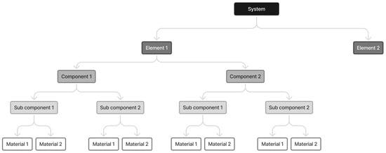
Figure 1 explains the difference between a material (M), a subcomponent (S), a component (C), an element (E), and a system (Sy).
Figure 1.
Hierarchical decomposition of a system from the system level to material level, illustrating the relationships between elements, components, subcomponents, and materials.
2.4. DfD on Use: Disassembly for Maintenance
The first criteria considered in this study focus on the maintenance operations in use. These criteria lead to either choosing longer lifespan parts or improving the detachability and accessibility of wear parts.
The first step is to identify the “wear parts” of the studied system:
- Parts that need maintenance;
- Critical parts that are susceptible to fail or break.
The second step is to detail the hardest connection type as well as the accessibility of the parts for each wear part that require an intervention within the calculated lifespan of the system. It is also required to mention the necessary number of interventions within the announced lifetime of the system.
The more the connection is accessible or detachable, the easier the maintenance will be; thus, the system will reach the expected lifespan. Conversely, if maintenance operations are made difficult, they may not be performed in the long term, which will affect the lifespan of the system. Thus, a score from 0.1 to 1 is awarded to each wear parts for both connection type and accessibility, 1 being attributed to the most detachable and most accessible connection and 0.1 being the worst case. For instance, a connection that does not require the use of an additional connection element (e.g., Velcro or magnetic connection) has a connection score of 1, and a connection type that is made with a hard chemical bound (such as Glue or Weld) has a connection score of 0.1.
Those scores, taken and adapted from Elma Durmisevic, are detailed in Table 1 and Table 2 [15]. Although the scoring criteria for connection type, accessibility, and damage were derived from existing literature, they were tested through application to several building-integrated envelope systems developed within the INFINITE project. This process allowed the verification of their relevance for facade-scale assemblies, where access constraints, environmental exposure, and layered construction are critical. Minor adaptations were therefore made to ensure consistency with the specific characteristics of building integrated systems.
Table 1.
Maintenance score evaluation—connection score, taken and adapted from [15].
Table 2.
Maintenance score evaluation—accessibility score, taken and adapted from [15].
The maintenance score therefore considers a fictive “lifespan” of the system, which corresponds to the announced lifespan of the system, adjusted with the number of maintenance interventions on the elements composing the system as well as the connection and accessibility score of the elements or assemblies (MLSn). This score increases with the ease of maintenance of the system. The criterion is expressed in years and as the percentage of the announced lifespan of the system, the objective being to maximize it in a design optimization approach. A score of 100% is reached when the calculated lifespan reaches the announced lifespan of the system. The maintenance score is calculated with the following formula:
where:
and:
- : maintenance score of the system.
- (years): announced lifespan of the system.
- (years): fictive “maintenance lifespan” of the system.
- (years): fictive maintenance lifespan of the element or assembly n.
- (years): fictive maintenance period, corresponding to the time between two maintenance interventions on the element or assembly n.
- (integer): number of maintenance interventions on the element or assembly n during the announced lifespan of the system ( for accidental failure).
- (0 to 1): connection score of the element or assembly n (hardest connection of the element or assembly, found in Table 1).
- (0 to 1): accessibility score of the element or assembly n (found in Table 2).
2.5. DfD End of Life: Disassembly for Reuse of the Parts
This criterion focuses on end of life in the INFINITE project scenario: the systems are entirely detached from the facade and disassembled in the factory.
The purpose is to reuse the parts on new systems to reduce waste production. To give a realistic reuse score, four parameters were considered in the reuse score:
- Connection type (the score attributed is detailed in Table 1).
- Damage on the parts, composed of damaged area and damage intensity (the scores attributed are detailed in Table 3 and Table 4). Each indicator can be assigned a different weight; however, for now, the same weight is considered for both damaged area and damage intensity. The resulting damage score is the average of damaged area and damage intensity indicators.
- Mass of the components.
Table 3.
Score attributed to each damage type, taken and adapted from [31].
Table 4.
Score attributed to each damage area type, taken and adapted from [31].
The disassembly for reuse score leads to favoring assemblies that allow the recovery of spare parts without damage.
The approach allows us to dismantle the systems step by step, until only the following remains:
- (a)
- Unitary reusable components.
- (b)
- Reusable assemblies of components.
- (c)
- Non-reusable components or assemblies.
The criterion is expressed as percentage of mass of (a + b) on the total mass of the system, the objective being to maximize it.
The formula used for the criterion calculation is provided below:
where:
Containing:
- : reuse score of the system.
- (kg): reusable mass of the element or assembly n.
- (0 to 1): connection score of the element or assembly n (hardest connection of the element or assembly, found in Table 1).
- (0 to 1): damage intensity on the element or assembly n (found in Table 3).
- (0 to 1): damaged area of the element or assembly n (found in Table 4).
- (0 to 1): damage score of the element or assembly n.
- (kg): mass of the element or assembly n.
- (kg): mass of the system.
2.6. DfD End of Life: Disassembly for Recycling
This criterion focuses on end of life. At this phase, the system is entirely detached and disassembled in the factory or on site to recycle the materials.
The approach is to dismantle the system step by step, until only the following remains:
- (a)
- Unitary recyclable components.
- (b)
- Assemblies of components of the same recyclable material.
- (c)
- Assemblies of unitary components that are not recyclable.
The criterion is expressed as percentage of mass of (a + b) on the total mass of the system; the objective is to maximize it.
This criterion leads to choosing recyclable materials and allowing separability by material type. Damaging the parts during disassembly does not affect recyclability if it is still possible to separate the materials.
The formula to be used is as follows:
Containing:
- : recyclability score of the system.
- (kg): recyclable mass of the element or assembly n.
- (0 or 1): recyclability of the element or assembly n.
- (0 to 1): connection score of the element or assembly n (hardest connection of the element or assembly, found in Table 1).
- (kg): mass of the element or assembly n.
- (kg): mass of the system.
2.7. DfD Global Score
The DfD Global score is the synthesis of the maintenance, reuse, and recycling scores of the system. This score allows designers to achieve a complete overview of the detachability of the developed solutions.
This value is represented as a percentage that is obtained by calculating the average of the 3 DfD scores. The formula to be used is as follows:
Containing:
- : global score of the system.
- : maintenance score of the system.
- : reuse score of the system.
- : recyclability score of the system.
3. Practical Implementation and Results
Partners of the INFINITE project were commissioned to develop envelope kits for specific uses, including solar thermal, photovoltaic, green facade, smart window, and air distribution. As the project places particular emphasis on the circularity aspects of the solutions design, the sustainability/circularity of the kits was assessed and validated by a life cycle analysis/life cycle costs study, and a DfD qualitative and quantitative analysis.
The aim of the project is to shift technologies at maturity levels 5 or 6 up to levels 7 or 8. To achieve this, various envelope technology manufacturers were able to draw on the DFD methodology presented in the previous section. In the remainder of this article, the application of the methodology is presented in detail for the Building Integrated Solar Thermal (BIST) kit (NOBATEK, Anglet, France and ARAMIS, Sens, France), while the results for the green facade and air distribution kits are briefly reported to verify the applicability of the method to envelope technologies with different functions, material compositions, and disassembly constraints, using the same scoring criteria and weighting factors described in Section 2.
3.1. Introducing BIST Technology
BIST is a sub-category of solar thermal panels, directly integrated into the architecture of the building. In the INFINITE project, the technology used is a water flat-plate unglazed solar thermal collector called BIST, integrated into the facade and used to pre-heat the source of a water-to-water heat pump for heating and domestic hot water production.
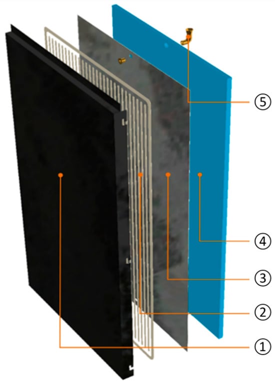
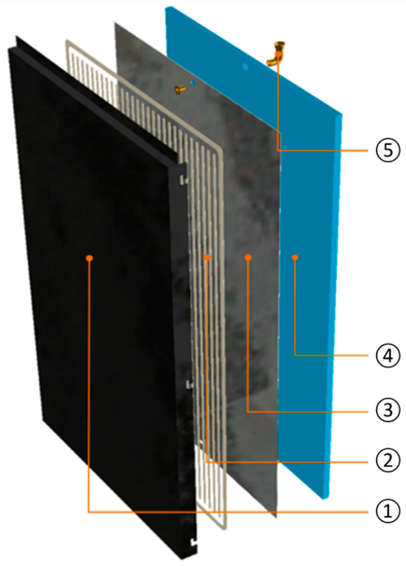
Figure 2 shows a detailed view of BIST. The front face (1) is made of aluminum, which makes it similar to cladding and facilitates its architectural integration. The size of this panel can vary between 0.5 m × 0.5 m (length × width) and 3 m × 1 m. A second aluminum plate (3) is glued to the back of the outer face using a 10 mm-thick bead of adhesive (2). The volume thus contained between the two plates allows the circulation of a heat-transfer fluid (water–glycol in our case), which captures the heat in the external surfaces when these are exposed to incident solar radiation. The fluid enters and leaves this volume via two connectors (5) at the top and bottom of the panel. To limit losses at the rear, insulation (4) is added to the aluminum plate. The performance of such a collector was simulated and measured, and this work has been the subject of a previous publication [36]. Once connected, the various BIST panels form a solar facade.
Figure 2.
Exploded view of the BIST panel—(1) aluminum cladding, (2) adhesive, (3) aluminum plate, (4) insulation, and (5) hydraulic connector.
3.2. Adapting Technology to the INFINITE Context
The objective of the INFINITE project, which is to design prefabricated facades, requires the bonds between the various components of the BIST technology to be improved. Maintaining the technology must be as easy as possible. In its initial version, the BIST panel is attached to the building using an offset aluminum structure the size of the building fixed to the facade using screws. The panels are attached to this structure using notches, which means that they must be installed in columns, from the bottom to the top. The hydraulic connectors are attached to the panel using an adhesive, in the same way as the insulation. Finally, the hydraulic manifolds are also screwed to the remote structure. This initial version of the system was evaluated using the DfD tool to identify areas for improvement in terms of maintenance, reuse, and recyclability. In our study, we are only interested in the facade part of the system, i.e., excluding the storage tanks and the heat pump. In addition, the cladding part of the BIST panel (numbers 1 to 3 in Figure 2) is considered as a single element, as it can only be replaced as a single unit.
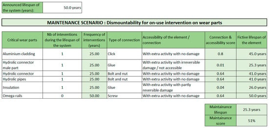
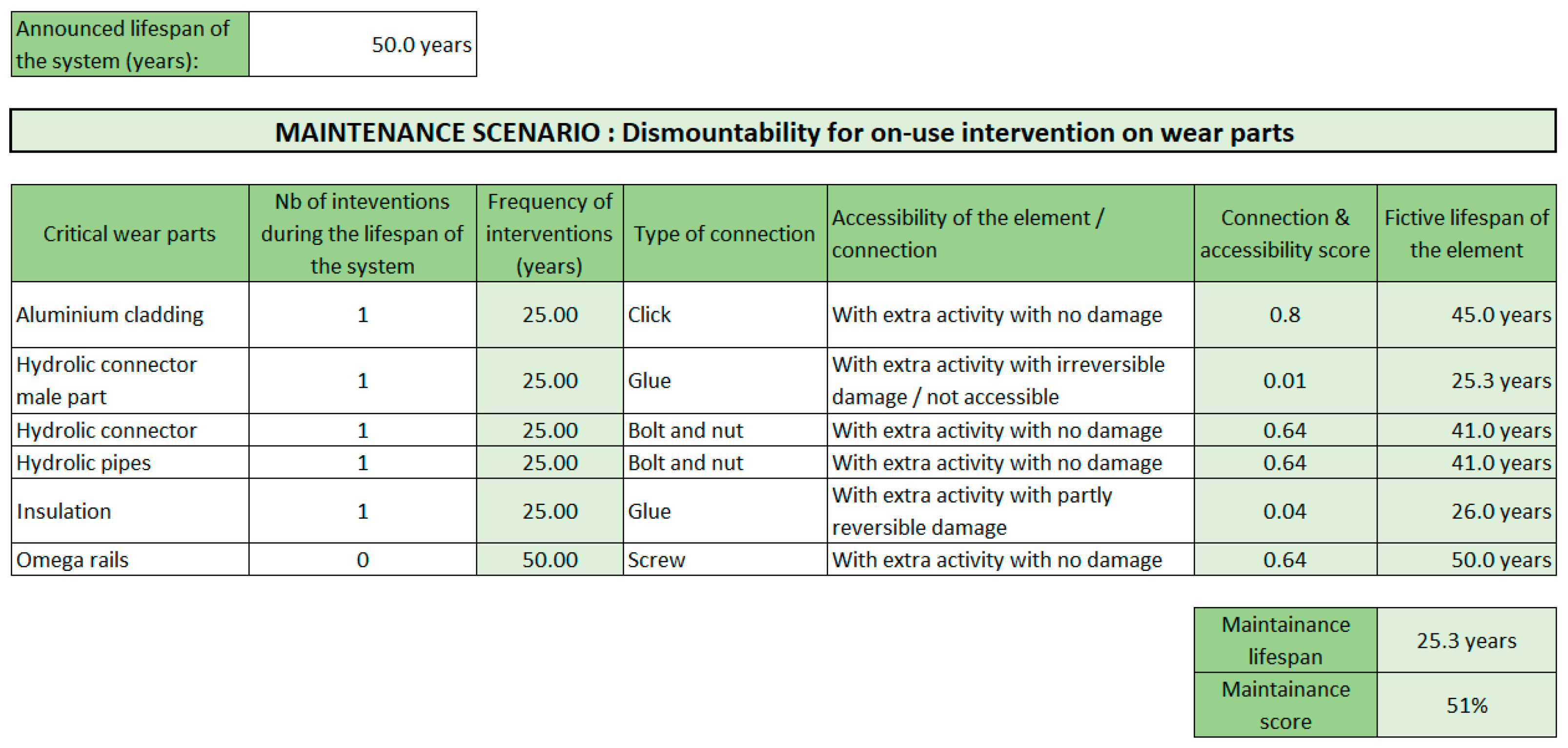
Figure 3 shows the values defined for BIST, with a system lifetime of 50 years. During this lifetime, it is considered that an intervention is necessary for each sub-element making up the system, except for the remote structure called “omega rail”. The type of connection as described in the previous paragraph is entered in the 4th column. The accessibility of the sub-component is entered in column 5 using predefined values. The choices are as follows:
Figure 3.
Presentation of the maintenance tab of the evaluation tool with the values defined for BIST.
- “Freely accessible” if no pre-action is required to access the component. Pre-action refers to any activity that must be carried out prior to working on the component itself.
- “With extra activity with no damage” if a pre-action is required to access the component.
- “With extra activity with reversible damage” if a pre-action is required to access the component and reparable damage may result from this action.
- “With extra activity with partly reversible damage” if a pre-action is necessary to access the component and little damage may result from this action.
- “With extra activity with irreversible damage/not accessible” if the intervention on this sub-component is impossible or risks causing irreversible damage exist.
If work is required on the cladding part of the panel, all the panels in the column must be unchecked beforehand. This is why the category “With extra activity with no damage” was chosen for this sub-element. All screwed sub-elements can be removed without damaging their respective supports, which is why the “With extra activity with no damage” category was chosen for the female part of the hydraulic connection, the feeders and the offset metal structure. As the insulation is glued to the rear of the panel, it can be detached at the risk of part of the insulation tearing off, which explains why the category “With extra activity with partly reversible damage” was chosen. Finally, the hydraulic connectors cannot be removed from their support, as this could compromise the watertightness of the panel.
In its initial version, the panel obtained a maintenance score of 51%, with an estimated maintenance lifespan of 25.3 years. The component with the greatest impact on this score is the male part of the hydraulic connector, followed by the insulation, which have accessibility scores of 0.01 and 0.04, respectively. Glued connections, which necessarily involve damage to the substrate or even non-accessibility, should be avoided. Improvements on these two items will therefore be prioritized. Screwed connections have a score of 0.64, which is satisfactory as it stands. Finally, the notch connection on the BIST panel shows a high accessibility score, which could be further improved by making the panel directly accessible without having to remove the other panels above it first.
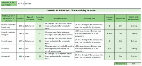
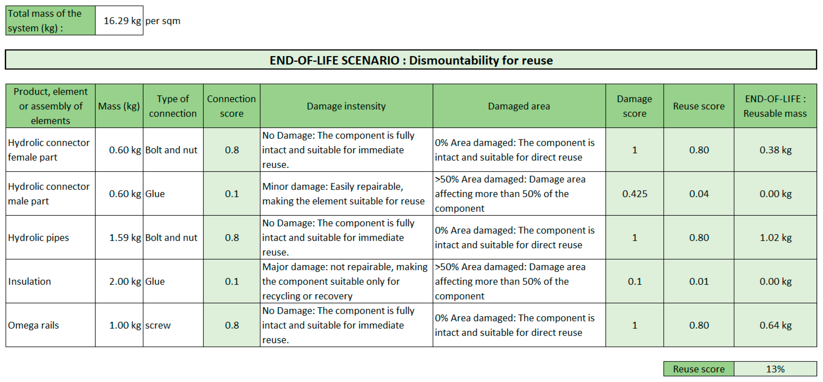
The second table of the DfD tool, shown in Figure 4, was used to assess the reusability of the system. The first column shows all the sub-components of the system that can be reused. The BIST panel is not shown because it cannot be reused as it stands. In addition to the architectural aspect of the cladding (specific colors and dimensions), its reuse would require complex operations for repairing bumps, scratches, and repainting. If the manufacturer is in the process of developing an industrial line for these operations, a recycling line for aluminum cladding is not yet operational. However, the mass of the aluminum cladding is considered in the total mass of the kit and in the reuse score. For each sub-component, the mass in column 2 and the type of connection in column 3 need to be specified. Columns 5 and 6 are used to select the state of the component after disassembly, from ”Minor damage” to “Major damage” and the area affected from “0% Area damaged” to “>50% Area damaged”, respectively. Except for the insulation, for which it is assumed that a part can be torn off during dismantling and for which a “Major damage/>50% Area damaged” status is defined, the other sub-elements are classified as “No damage/0% Area damaged”.
Figure 4.
Presentation of the reuse tab of the evaluation tool with the values defined for BIST.
As it stands, the BIST system has a reuse score of 13%. Of the elements listed, the insulation has the worst connection and damage scores, both at 0.1. This is due to the use of glue for fixing, which poses a high risk to the material during dismantling. As this sub-element represents 12% of the mass of the whole system, it has a major impact on the result. The second lowest ranked component is the male part of the hydraulic connector with a connection score of 0.1, for the same reason. However, its reuse score is better than that of the insulator because, being made of aluminum, it is not likely to be damaged when dismantled. The other elements have scores of 0.8 because their screw connection means they can be dismantled without damage.
Efforts to improve should therefore focus primarily on securing the insulator and to a lesser extent on securing the male connector.
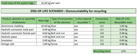
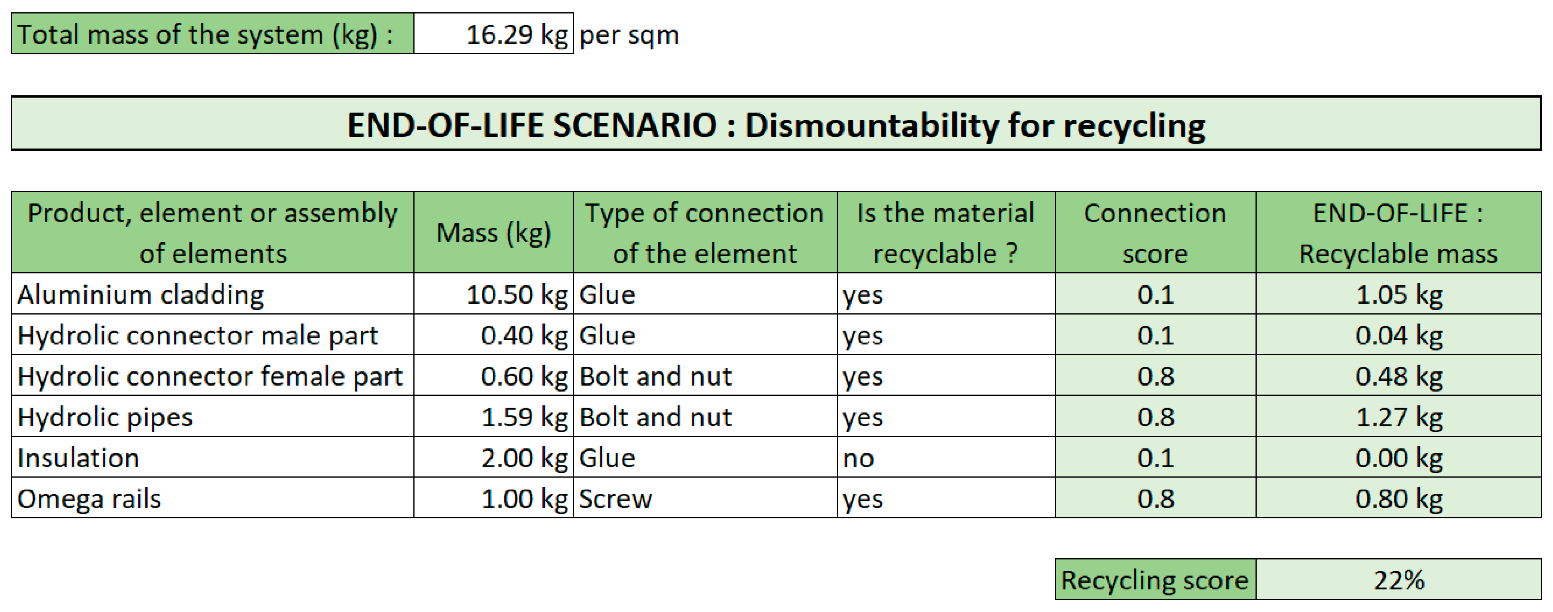
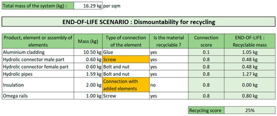
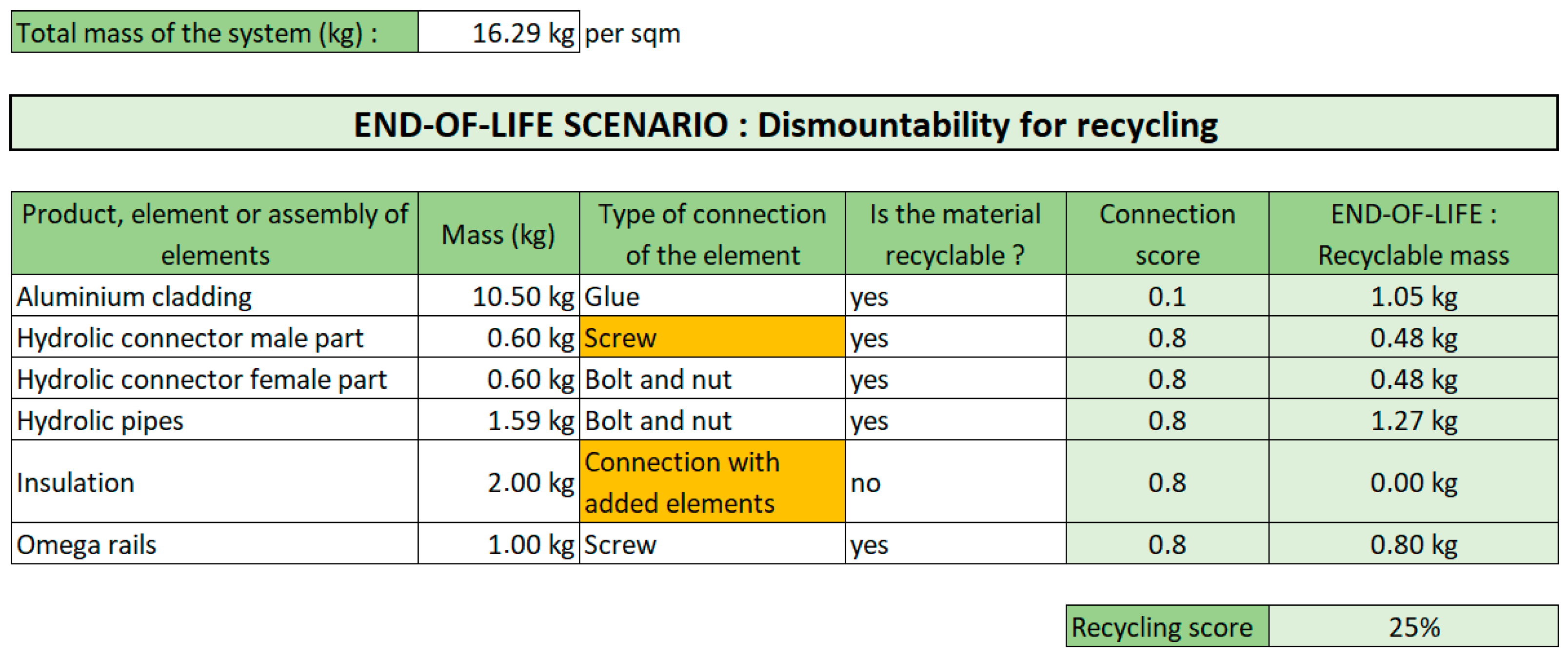
Finally, the last tab of the tool is used to assess the recyclability of the system. As with the previous two tabs, it is necessary to list all the sub-elements making up the system. Column 2 must also specify whether the material used for the sub-component is recyclable. Figure 5 shows the fields filled in for the recycling tab of the tool. Except for aluminum cladding, the fields are identical to those for the reuse tab. For this part, the type of connection for the aluminum cladding is not considered as ”click” but as “glue”. In fact, we are interested here in the possibility of separating the two sheets of aluminum that make up the cladding.
Figure 5.
Presentation of the recycling tab of the evaluation tool with the values defined for BIST.
The BIST system achieved a recyclability score of 22%, since the aluminum cladding and the male connector are bonded. The insulation, which is also glued, was not included in the calculation because it was not recycled. As the other sub-components are screwed, they all have a connection score of 0.8. However, as their combined weight represents only 20% of the system total, they have only a marginal impact on the recyclability score.
To improve the recyclability score, work needs to be done on the connection of the aluminum cladding and the male hydraulic connector.
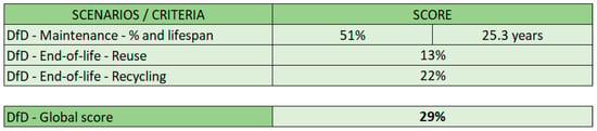
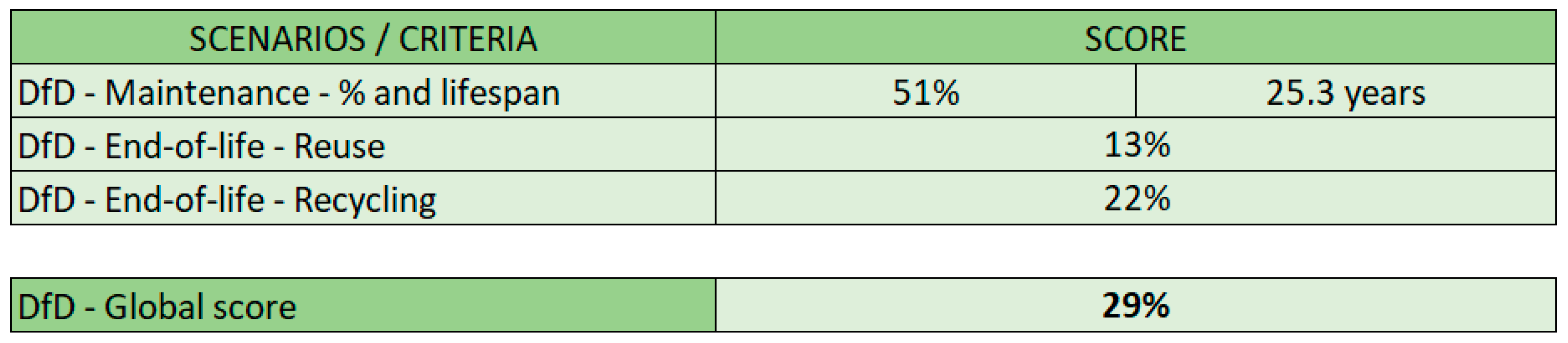
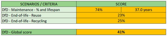
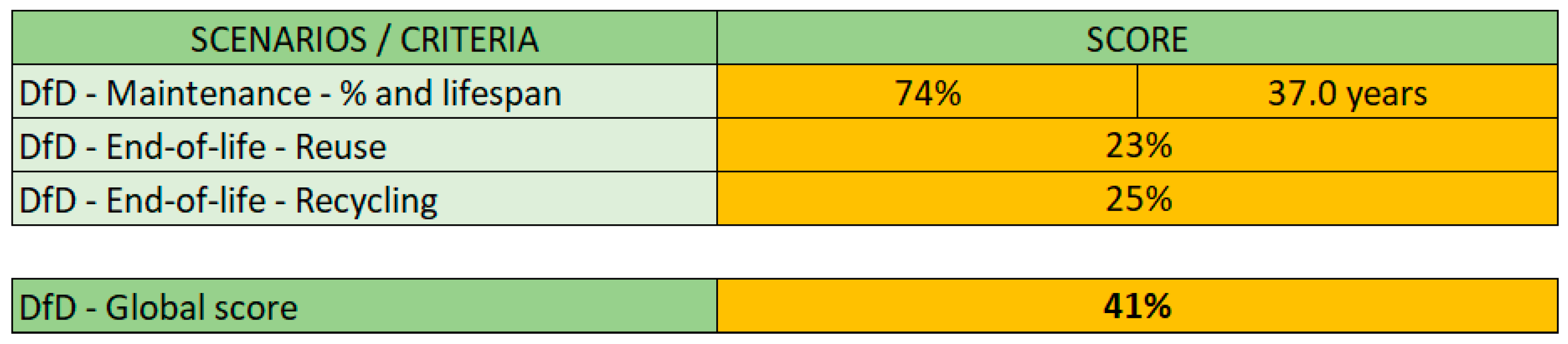
In summary, Figure 6 shows the global table of the DfD score of the BIST.
Figure 6.
DfD global result tab for the BIST.
3.3. DfD Assessment Following Modifications
At this stage, the study of maintenance, reuse, and recyclability scores shows that the sub-components with the greatest impact are the insulation, the male connector, and the aluminum cladding. The method of assembling the two sides of the cladding had been the subject of in-depth research prior to the INFINITE project, and it seemed complicated for the manufacturer to modify this connection. This is why efforts were made to improve the connections between the insulation and the male connector, with the knowledge that the optimum result would not be achieved for all three scores.
Originally, the insulation was glued to the rear face of the cladding for simplicity of manufacture. However, because of its position, this sub-component is protected from the main external elements that can place it under stress. To facilitate dismantling during the various life phases, the connection has evolved towards deformable fixing strips. These secure the insulation against the rear face of the cladding and can be unfolded if the insulation needs to be removed. In terms of evaluation, this means that the type of connection can be changed from “glue” to “connection with added elements”, without causing any damage during dismantling.
Fixing the male connector with glue also provided a seal. This property was recovered with screw connectors that compress an O-ring. The disadvantage of this solution, however, is that the seal has to be replaced each time the connector is disassembled, as a precautionary measure to ensure that the assembly remains watertight. So, disassembly causes reversible damage. Figure 7 shows the modified fields in the tool as a function of the changes made to the solution.
Figure 7.
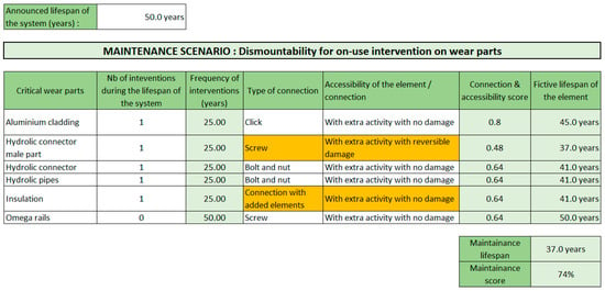
Modification of the fields entered in the maintenance tab following changes to the connections.
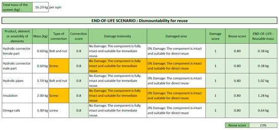
Compared to the original, the maintenance, reuse, recyclability, and global DfD scores of the BIST increased by 23, 10, 3, and 12 points, respectively, as shown in Figure 7, Figure 8, Figure 9 and Figure 10. The maintenance lifespan increased by 11.7 years, which is more in line with the context of prefabricated facades, where maintenance work must be limited. To further improve this score, it would be necessary to be able to freely access all the elements that make up the BIST. However, these should be hidden from view for better architectural cohesion. The last easily accessible point for improvement would be to move away from hydraulic sealing using O-ring seal, towards “Plug and Play” solutions, solutions that are being considered for a future version of the technology. The other two scores improved more moderately since it was not possible to reuse the BIST panel, and because the manufacturer did not want to modify its process for gluing the two sides of the cladding. The hydraulic connector solution could also slightly improve the reuse score, as the dismantling process no longer generates any damage. Finally, the use of recyclable insulation adapted to the outdoor context, such as wood panels, would improve the recyclability score, but this would be at the expense of the solution’s point per square meter.
Figure 8.
Modification of the fields entered in the reuse tab following changes to the connections.
Figure 9.
Modification of the fields entered in the recycling tab following changes to the connections.
Figure 10.
Modification of the DfD global result tab following changes to the connections.
3.4. Green Facade and Air Distribution: Results for Method Validation
The methodology was applied to assess a green facade system consisting of climbing plants (Green Cable Heavy RSK). The lifespan considered for the assessment was aligned with that of the supporting structure (50 years). In the evaluated configuration, the plants grow directly in the ground, and the soil is therefore not considered part of the kit. The functional unit corresponds to one line of climbing plants with a height of 10 m, including two anchors.
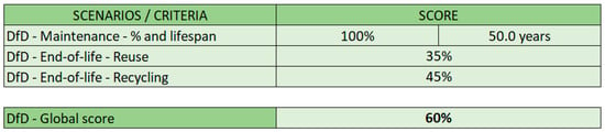
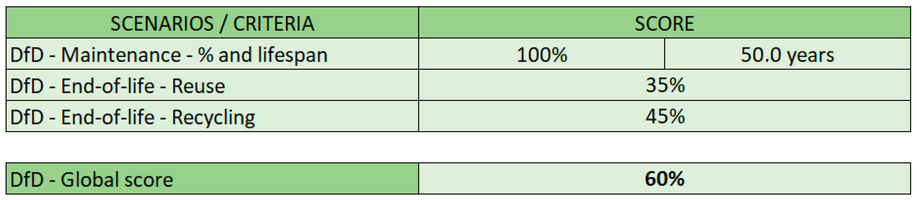
The results are presented in Figure 11. The kit is mainly composed of metallic elements that are recoverable and replaceable, which leads to a high maintenance score. The reuse and recycling scores are affected by the weight of the plants, which are immovable and not valorized, as the assessment tool does not consider composting options. For the end-of-life reuse and recycling calculations, the cantilever and cable components account for approximately half of the total mass. These elements are connected by bolts, allowing disassembly without damage and enabling reuse and recycling, resulting in scores of 35% and 45%, respectively.
Figure 11.
DfD results for the green facade system.
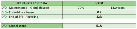
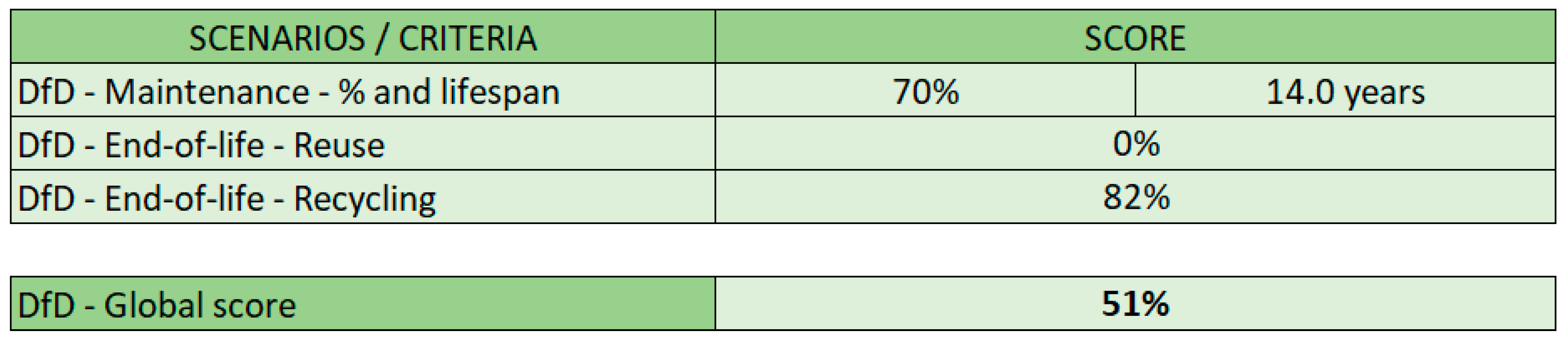
The methodology was also applied to assess an air distribution and ventilation kit to be installed on the facade of a building. In this system, frequent maintenance is required, particularly for the heat exchanger filters. The results are presented in Figure 12. As all active and passive components are accessible and the connections are fully demountable, the maintenance score reached 70%, indicating a configuration well-suited to regular maintenance operations. Metallic components (casing and EPP body) and plastic components (piping) together account for approximately three-quarters of the total system mass. All components are connected using screws and clip-based fixings, which enable effective separation at end of life and result in a recycling score of 82%.
Figure 12.
DfD results for the air distribution system.
As a limitation, the reuse phase was not considered for this kit due to the very low likelihood of reconditioning typically associated with HVAC equipment. Factors such as technological obsolescence and the limited feasibility of local repair significantly reduce reuse potential; therefore, this phase was excluded from the assessment.
4. Discussion
Existing approaches for assessing Design for Disassembly vary significantly in scope, data requirements, and intended stage of application. Quantitative methods such as those developed within the Alba Concepts and DRIVE-0 frameworks provide detailed assessments, but typically rely on extensive material inventories and environmental indicators, which limits their applicability during early design phases. Holistic frameworks, such as the Arup Circular Buildings Toolkit, support alignment with circular economy principles at the building scale but are primarily qualitative or semi-quantitative. End-of-life assessment tools, including those focusing on dismantling outcomes, offer valuable insights into real disassembly processes but are inherently restricted to post-use scenarios.
In contrast, the methodology proposed in this study was intentionally designed as a simplified, quantitative tool for early-stage design support. By relying on limited input data that are readily available to designers, it enables a rapid comparison of design options and identification of disassembly–critical interfaces without requiring prior environmental studies. The proposed approach therefore complements existing methods by filling the gap between qualitative design guidance and data-intensive, end-of-life–oriented assessments. This simplified structure results in high computational efficiency, enabling a fast evaluation without complex calculations or extensive datasets. Moreover, the tool based on the methodology proposed in this article is intended to assist manufacturers in their design choices, by helping them to anticipate maintenance and end-of-life stages and to increase awareness of their technologies, both at the SoA (State of Art) stage and in future scenarios. As this tool is intended to be as widely used as possible, it is important to consider the experience of manufacturers. To this end, as part of the INFINITE project, their feedback was compiled and will be used as points of improvement for future versions of the tool.
Based on the feedback provided by the manufacturer, the tool was found to be easy to use, but not necessarily adaptable to each specificity of the technologies it evaluates. One recurring comment we received was that the tool does not consider the obsolescence of the studied systems. In the case of BIST, this was evident in the non-reusable cladding, which was of a specific size and color. Similarly, the potential for the reuse of the air conditioning kit has not been assessed because the manufacturer estimated that only its plant would have been able to dismantle and upgrade spare parts, but there are no plans to deploy this activity. Moreover, the manufacturer estimates that the performance of the kit will be obsolete by end of the kit’s life. Another limitation of the tool is that it does not allow for the inclusion of end-of-life options other than those predefined. For example, in the case of a green facade, part of it can be composted. This waste recovery is not considered, as plant matter does not fall into the reuse or recycling categories. In addition, during the maintenance phase, the tool does not distinguish between the replacement and repair of components, which means that the waste produced during the life of the product cannot be accounted for. In the case of BIST, we saw that each time the hydraulic connectors were serviced, the O-rings had to be replaced. These are not counted as waste. There is no distinction made in the nature of the components that can be recycled, and the impact this has on the complexity of recycling. Whereas aluminum parts are easily managed by recycling chains, plastics are more easily incinerated or buried, even though they could be recycled, thus becoming final waste. Finally, we also saw from the BIST example that design choices may have been made before the technology was evaluated by the tool, such as the bonding of the two aluminum panels making up the cladding. To get the most out of the tool, it is important that it is used as early as possible in the design of the product being assessed.
From a methodological point of view, the reuse and recycling scores presented in this article were calculated based on the ratio between the reusable or recyclable mass and the total mass of the system. Consequently, the methodology does not favor one design option over another, even if the former is more relevant in terms of end-of-life waste generation. Finally, one of the main constraints of the project was to develop a DfD assessment methodology that did not require preliminary studies of the solution. For this reason, the environmental impact of each material was not considered as a weighting factor in the calculation of scores; however, this represents a limitation of the methodology, as components with low mass but potentially high environmental or health impacts may be undervalued in the assessment. Therefore, in practical applications, designers are encouraged to manually flag low-mass, high-toxicity materials when interpreting the results. Consequently, a solution with the best reuse and recycling score is not necessarily the most environmentally friendly one.
One area for improvement in the methodology would therefore be to calculate a non-reusable and non-recyclable mass in addition to the reuse and recycling scores proposed in this article. These results can support designers in transcending the constraints of ratio-based assessment methods, allowing for a more holistic appraisal of their systems’ circularity. As a further development, the integration of environmental impact and cost indicators would allow a more balanced and representative assessment, as a mass-based analysis alone cannot fully capture the overall sustainability performance of building systems. Moreover, experimental studies based on the primary data from real dismantling activities would be essential to further validate the methodology and strengthen its practical relevance.
5. Conclusions
This article introduced a methodology for evaluating Design for Disassembly (DfD) applied to prefabricated facades systems used in building renovation. To ensure broad applicability across different facade solutions, the methodology was deliberately designed to operate without requiring prior environmental or technical studies. This was achieved by relying on disassembly and recycling scores derived from the mass of facade components and the nature of their connections.
The methodology was tested on a Building Integrated Solar Thermal (BIST) facade case study in detail and two more technologies for methodology validation. The application of the methodology to additional facade technologies, including green facade and air distribution systems, further confirms its applicability across building integrated solutions with different functions and assembly logics. Across the assessed cases, the methodology consistently helped us identify critical disassembly points and design improvement opportunities, especially those related to accessibility and maintenance-friendly connections. Applied across the various technologies developed within the INFINITE project, the methodology generated strong interest among industrial partners, who recognized its usefulness in anticipating maintenance needs and end-of-life management during the early design phases.
Several limitations also emerged. Certain end-of-life scenarios—such as component compostability or obsolescence—were not captured by the current scoring system. In addition, because the method relies on ratio-based indicators, the total mass of the solution does not influence the results, which prevents lighter, potentially more recyclable solutions from being distinguished. Finally, as reducing environmental impact is the ultimate objective, future developments should consider integrating material type into the scoring process; moreover, the results should be interpreted with caution, particularly when low-mass components may have disproportionately high environmental impacts. Any refinement, however, must preserve the adaptive nature of the tool and avoid introducing the need for preliminary analyses.
Author Contributions
Conceptualization, M.L.; Methodology, M.D., P.R., M.L., S.R., P.B., and M.Z.; Software, M.L.; Validation, M.G. and M.Z.; Formal analysis, M.D., P.R., S.R., and P.B.; Investigation, M.D., P.R., M.G., and M.Z.; Resources, M.G. and M.Z.; Writing—original draft, M.D. and P.R.; Writing—review and editing, M.L., S.R., P.B., M.G., and M.Z.; Supervision, P.B.; Project administration, M.G.; Funding acquisition, P.B. and M.G. All authors have read and agreed to the published version of the manuscript.
Funding
This paper is part of the research activities conducted for the INFINITE project, funded by the European Union’s Horizon 2020 research and innovation program under grant agreement No 958397.
Data Availability Statement
The original contributions presented in this study are included in the article. Further inquiries can be directed to the corresponding author(s).
Acknowledgments
During the preparation of this manuscript/study, the authors used ChatGPT 5.1 for the purpose of generating a part of the abstract. The authors have reviewed and edited the output and take full responsibility for the content of this publication.
Conflicts of Interest
Authors Maxime Deru, Pierre Roger, Maia Louvard, Saed Raji, and Pascale Brassier were employed by the company NOBATEK; authors Martino Gubert and Marzieh Zarei were employed by the company Eurac Research. All authors declare that the research was conducted in the absence of any commercial or financial relationships that could be construed as a potential conflict of interest.
References
- European Environment Agency. Addressing the Environmental and Climate Footprint of Buildings; European Environment Agency: Copenhagen, Denmark, 2024. [Google Scholar]
- Alabdulrazzaq, H.; Gasparri, E.; Brambilla, A.; Attia, S. A Framework for Circular Facade Design: Systematic Review of Design Strategies and Performance Indicators. J. Clean. Prod. 2025, 536, 147140. [Google Scholar] [CrossRef] [Scilit]
- Ragonnaud, G. Revision of the Construction Products Regulation; European Parliamentary Research Service: Brussels, Belgium, 2024. [Google Scholar]
- Lu, Y.; Zhang, Y.; Huang, Z.; Cheng, B.; Wang, C.; Sun, Y.; Zhang, H.; Li, J. A Literature Review of Sustainable Building Research: Bibliometric Analysis from 2015–2025. Buildings 2025, 15, 3609. [Google Scholar] [CrossRef] [Scilit]
- Roberts, M.; Allen, S.; Clarke, J.; Searle, J.; Coley, D. Understanding the Global Warming Potential of Circular Design Strategies: Life Cycle Assessment of a Design-for-Disassembly Building. Sustain. Prod. Consum. 2023, 37, 331–343. [Google Scholar] [CrossRef] [Scilit]
- Eberhardt, L.C.M.; Birgisdóttir, H.; Birkved, M. Life Cycle Assessment of a Danish Office Building Designed for Disassembly. Build. Res. Inf. 2019, 47, 666–680. [Google Scholar] [CrossRef] [Scilit]
- Derikvand, M.; Fink, G. Design for Deconstruction: Benefits, Challenges, and Outlook for Timber–Concrete Composite Floors. Buildings 2023, 13, 1754. [Google Scholar] [CrossRef] [Scilit]
- Seddiki, M.; Bennadji, A. A Life Cycle Carbon Assessment and Multi-Criteria Decision-Making Framework for Building Renovation Within the Circular Economy Context: A Case Study. Buildings 2025, 15, 1894. [Google Scholar] [CrossRef] [Scilit]
- Boothroyd, G.; Alting, L. Design for Assembly and Disassembly. CIRP Ann. 1992, 41, 625–636. [Google Scholar] [CrossRef] [Scilit]
- ISO 20887:2020; Sustainability in Buildings and Civil Engineering Works—Design for Disassembly and Adaptability—Principles, Requirements and Guidance. International Organization for Standardization (ISO): Geneva, Switzerland, 2020.
- Ostapska, K.; Rüther, P.; Loli, A.; Gradeci, K. Design for Disassembly: A Systematic Scoping Review and Analysis of Built Structures Designed for Disassembly. Sustain. Prod. Consum. 2024, 48, 377–395. [Google Scholar] [CrossRef] [Scilit]
- Attia, S.; Al-Obaidy, M.; Mori, M.; Campain, C.; Giannasi, E.; van Vliet, M.; Gasparri, E. Disassembly Calculation Criteria and Methods for Circular Construction. Autom. Constr. 2024, 165, 105521. [Google Scholar] [CrossRef] [Scilit]
- Kara, S.; Pornprasitpol, P.; Kaebernick, H. A Selective Disassembly Methodology for End-of-Life Products. Assem. Autom. 2005, 25, 124–134. [Google Scholar] [CrossRef] [Scilit]
- Brand, S. How Buildings Learn: What Happens After They’re Built; Penguin Books: London, UK, 1994; ISBN 978-0-670-83515-7. [Google Scholar]
- Durmišević, E. Transformable Building Structures; Design for Disassembly as a Way to Introduce Sustainable Engineering to Building Design & Construction. Doctoral Thesis, Delft University of Technology, Delft, The Netherlands, 2006. [Google Scholar]
- Drive 0. Available online: https://www.drive0.eu/reports/ (accessed on 29 January 2025).
- Dutch Green Building Council (DGBC); Alba Concepts; Rijksdienst voor Ondernemend Nederland; W/E Adviseurs. Circular Buildings. Disassembly Potential Measurement Method. Version 2.0; Dutch Green Building Council (DGBC): Delft, The Netherlands, 2021. [Google Scholar]
- Daly, P. A Critical Review of Circularity—‘Design for Disassembly’ Assessment Methods Applied in the Development of Modular Construction Panels—An Irish Case Study. e-Prime Adv. Electr. Eng. Electron. Energy 2023, 5, 100252. [Google Scholar] [CrossRef] [Scilit]
- Salonen, N. Evaluating Circularity Metrics on Industrial Lifting Equipment. Bachelor’s Thesis, University of Applied Sciences, South-Eastern Finland, Kouvola, Finland, 2025. [Google Scholar]
- Kentie, N. Reusability Potential in the Building Circularity. An Assessment Tool to Assess the Reusability Potential of Individual Building Products in an Early Design Stage in Order to Support Circular Decision-Making in the Built Environment. Master’s Thesis, Eindhoven University of Technology, Eindhoven, The Netherlands, 2021. [Google Scholar]
- Ottenhaus, L.-M.; Hernández-Aldaz, M.; Davies, A.; Cabrero, J.M. Evaluating the Disassembly Potential of Timber Buildings: Development of Calculation Tool and Proof of Concept. Wood Mater. Sci. Eng. 2025, 20, 881–909. [Google Scholar] [CrossRef] [Scilit]
- Keivanpour, S. A Fuzzy Sustainable Quality Function Deployment Approach to Design for Disassembly with Industry 4.0 Technologies Enablers. In Manufacturing Driving Circular Economy; Kohl, H., Seliger, G., Dietrich, F., Eds.; Lecture Notes in Mechanical Engineering; Springer: Cham, Switzerland, 2023; pp. 772–780. [Google Scholar] [CrossRef] [Scilit]
- Grüter, C.; Gordon, M.; Muster, M.; Kastner, F.; Grönquist, P.; Frangi, A.; Langenberg, S.; De Wolf, C. Design for and from Disassembly with Timber Elements: Strategies Based on Two Case Studies from Switzerland. Front. Built Environ. 2023, 9, 1307632. [Google Scholar] [CrossRef] [Scilit]
- Verberne, J.J.H. Building Circularity Indicators. Available online: https://research.tue.nl/en/studentTheses/building-circularity-indicators (accessed on 11 February 2025).
- van Vliet, M. Disassembling the Steps towards Building Circularity: Redeveloping the Building Disassembly Assessment Method in the Building Circularity Indicator. Master’s Thesis, Eindhoven University of Technology, Eindhoven, The Netherlands, 2018. [Google Scholar]
- Drive 0. Available online: https://www.drive0.eu/ (accessed on 12 February 2025).
- Ellen MacArthur Foundation; Granta Design. Circularity Indicators. An Approach to Measuring Circularity: Project Overview; Ellen MacArthur Foundation: New York, NY, USA, 2015; Available online: https://content.ellenmacarthurfoundation.org/m/5df196c8314ff61f/original/Circularity-Indicators-Project-Overview.pdf (accessed on 9 February 2026).
- ARUP Circular Buildings Toolkit. Available online: https://ce-toolkit.dhub.arup.com/strategies (accessed on 26 January 2026).
- Eurac Research Circular Lab Assessment. Available online: https://itat-attention.eu/en/project/circular-lab-assessment/ (accessed on 9 February 2026).
- Eurac Research Circular Design Assessment. Available online: https://itat-attention.eu/en/project/circular-design-assessment-2/ (accessed on 9 February 2026).
- Gubert, M.; Toniato, G.; Papaiz, L.; Avesani, S. End of Life Tool for Building Product Development: The Solar Window Block Case Study; Associazione Rete Italiana LCA: Milan, Italy, 2021; pp. 191–198. [Google Scholar]
- Durmiševic´, E.; Beurskens, P.R.; Adrosevic, R.; Westerdijk, R. Systemic View on Reuse Potential of Building Elements, Components and Systems - Comprehensive Framework for Assessing Reuse Potential of Building Elements; Delft University of Technology: Delft, The Netherlands, 2017; pp. 275–280. [Google Scholar]
- Durmišević, E. Reversible Building Design. In Designing for the Circular Economy; Charter, M., Ed.; Routledge: Abingdon, UK; New York, NY, USA, 2018; pp. 344–359. ISBN 978-1-315-11306-7. [Google Scholar]
- European Commission. A New Circular Economy Action Plan for a Cleaner and More Competitive Europe; Publications Office of the European Union: Brussels, Belgium, 2020. [Google Scholar]
- Cramer, J. Building a Circular Future: Ten Takeaways for Global Changemakers. Available online: https://circulareconomy.europa.eu/platform/en/knowledge/building-circular-future-ten-takeaways-global-changemakers (accessed on 11 February 2025).
- Martinez, R.G.; Goikolea, B.A.; Paya, I.G.; Bonnamy, P.; Raji, S.; Lopez, J. Performance Assessment of an Unglazed Solar Thermal Collector for Envelope Retrofitting. Energy Procedia 2017, 115, 361–368. [Google Scholar] [CrossRef] [Scilit]

Disclaimer/Publisher’s Note: The statements, opinions and data contained in all publications are solely those of the individual author(s) and contributor(s) and not of MDPI and/or the editor(s). MDPI and/or the editor(s) disclaim responsibility for any injury to people or property resulting from any ideas, methods, instructions or products referred to in the content. |
© 2026 by the authors. Licensee MDPI, Basel, Switzerland. This article is an open access article distributed under the terms and conditions of the Creative Commons Attribution (CC BY) license.