


Abstract
This study evaluates the resistance of existing reinforced concrete buildings to progressive collapse using the Tie-Force Method specified in UFC 4-023-03. Five multi-storey residential reinforced concrete buildings in different regions are analysed. In situ rebar scanning and Schmidt hammer tests revealed existing reinforcement layouts and concrete strengths (14–26 MPa). From the measured geometries, material properties and design loads, the required peripheral, longitudinal–transverse and vertical tie forces are calculated and converted into equivalent reinforcement areas. The results show that none of the investigated buildings satisfies all tie-force requirements with its current detailing. In particular, approximately 40% of the total Ø12 reinforcement required for the most critical peripheral ties in the other functional areas is concentrated in a single building. For longitudinal and transverse ties within the slab plane, additional Ø12 bars are required, especially along the most unfavourable grid lines in large-span panels. Vertical tie demands are modest and can generally be met with about 1–7 Ø16 bars in the selected columns. The findings indicate that, in the investigated sample, tie-force deficiencies appear to be governed more by design era and structural layout than by geographic location, and that strengthening slab-plane ties is critical for improving progressive-collapse resistance in the investigated buildings. In typical existing RC frame buildings, tie-force inadequacy is governed primarily by slab-plane ties rather than by vertical ties and the variation in required tie reinforcement across buildings is controlled more by design era and plan-geometry/floor-load characteristics than by geographic location.
1. Introduction
In the early to mid-twentieth century, design engineers and project practitioners in many countries adopted broadly similar approaches to building design and project development. Statistical parameters specified in the relevant codes, derived from various experimental and observational studies, were taken as the primary basis for design. In the past, structures were generally able to complete their service lives without major problems, largely because the actions to which they were subjected were relatively limited.
Countries account not only for certain common types of loads but also for loads differentiated according to their geographical conditions, in order to ensure that structures remain safely standing. For many years, structures have been designed within this framework and made available for public use. For example, in the United States, unlike in some other countries, tsunami and ice loads are also considered in building codes [1,2]. Each country can determine the relevant loads and associated design values in line with its specific conditions and technological capabilities; consequently, every country develops design practices suited to its own context.
In the morning of 16 May 1968, the pressure generated by a gas explosion on the 18th floor of the 22-storey Ronan Point apartment tower blew out the walls of the flat and caused a partial collapse of the building [3,4,5]. The Ronan Point collapse revealed the inadequacy of the provisions concerning overall structural integrity in existing building codes and led to regulatory changes in the United Kingdom, the United States, and Canada [6]. In particular, the UFC 4-023-03 Design of Buildings to Resist Progressive Collapse [7] and the GSA Alternate Path Analysis and Design Guidelines for Progressive-Collapse Resistance [8] codes recommend methods for progressive-collapse analysis. The analytical procedures considered herein are the Alternate Path Method (APM), the Tie-Force Method (TFM), and the Enhanced Local Resistance Method (ELRM). Among these, the Tie-Force Method is of primary interest in the present study, and the subsequent subsection outlines key contributions from the literature related to TF provisions and their role in mitigating progressive collapse.
Despite its practical relevance, the TFM has received relatively limited attention in the existing literature. For this reason, the present study adopts the TFM as the basis for the analytical assessment and provides a focused review of previous research on tie-force provisions.
In this context, an enhanced TF formulation is proposed, in which the code-based constant tie-force requirement is replaced by a demand-based expression derived from the actual structural response, and the internal and peripheral tie requirements are defined in terms of the member stress–strain states. Numerical investigations on three- and eight-storey reinforced concrete frames indicate that the improved TF design increases the total amount of beam reinforcement in an eight-storey frame by only about 6.5% compared to conventional seismic design, while preventing collapse under the considered column-removal scenarios and leading to a more rational distribution of tie forces over the height. By contrast, for frames designed for lower seismic intensities, reinforcement increases of approximately 26% and 41% are required to achieve a comparable level of robustness, highlighting the pronounced sensitivity of TF-based design to the underlying seismic demand [9]. Subsequent studies have sought to further rationalise TF-based design, particularly for longitudinal and transverse tying in multi-storey buildings. A longitudinal and transverse TFM has therefore been developed with the dual objective of robustness design and limitation of progressive collapse, in which tie demand is related directly to local damage scenarios such as sudden loss of a column or load-bearing wall and ductility is represented by a chord-rotation capacity together with an associated dynamic amplification factor. The design expression is written in terms of a tie-force intensity factor fi, a normalised chord rotation α and a dynamic factor η. Comparisons with current provisions show that the constant tie forces in UFC 4-023-03 correspond to fi ≈ 3.0 for α = 0.2 rad, whereas Eurocode 1 [10] rules give only fi ≈ 0.8 for typical ductility levels, while static equilibrium of double-span beams requires about fi ≈ 2.5 at α = 1.0, indicating that existing tie-force requirements lack a consistent ductility-based rationale [11]. Following the development of the rational longitudinal and transverse TFM, subsequent work has focused on refining the representation of floor-system resistance and stiffness through simplified mechanics-based models, leading to an enhanced procedure that is suitable for codification [12].
TF provisions have also been examined for mass-timber systems, particularly platform-type cross-laminated timber (CLT) buildings, where existing European and American tie-force requirements are difficult to apply directly because of connection detailing and construction characteristics. An indirect tie-force procedure tailored to mid-rise CLT construction has therefore been proposed and applied to an eight-storey residential building, providing a practical TF-based approach to disproportionate collapse prevention in such structures [13]. In addition to platform-type CLT buildings, the TF concept has also been applied to a mid-rise post-and-beam timber frame subjected to internal and edge column-loss scenarios. A specially detailed steel–timber beam–column connection is analysed, and the results show that appropriate connection detailing can satisfy TF demands and reduce the risk of progressive collapse in such systems [14].
A recent book chapter applies the UFC TFM step-by-step to a six-storey RC building in Yozgat/Sorgun (6.4 kN/m2 floor load), determines peripheral, internal and vertical tie-force demands (e.g., ≈211 kN for a peripheral tie satisfied by 3Ø16 bars) and emphasises that, if these demands cannot be met, redesign or adoption of the Alternate Path Method and careful checks of continuity and joint detailing are required [15].
It has been reported that, for RC beam–slab substructures subjected to column loss, considering slab action can increase the ultimate resistance by about 60% compared with beam-only substructures [16], slabs may contribute more than one-third of the total load-carrying capacity [17], and the use of rubberised concrete further enhances ductility and catenary-stage performance without reducing the overall progressive-collapse resistance [18,19]. An early analytical study on large-panel (LP) buildings used a rigid-panel–elasto-plastic-spring model to simulate local panel destruction due to gas explosion and showed, via a cantilever collapse mechanism, that the minimum tensile joint force required to prevent collapse increases from about 140 kN under quasi-static loading to roughly 150–180 kN when dynamic effects and shorter load durations are considered, with upper-storey panels requiring noticeably stronger horizontal joints than lower ones [20]. Consistent with these studies, a dynamic progressive-failure analysis was performed on an elastic–brittle multi-storey frame with a total span of 10.00 m, subjected to a horizontal sinusoidal load of ±1000 kN in the x-direction. The first and second natural frequencies of the system decrease from 17.42 to 14.71 and from 27.69 to 24.42 after failure of the exterior frame, while higher modes (e.g., 51.19 to 53.45) also shift. In the subsequent step, the intermediate frame fails and the numerical model predicts complete collapse, showing how a small number of member failures can drive global instability under the considered motion [21].
Contemporary practice for assessing progressive collapse in existing buildings generally relies on two main approaches: robustness provisions, such as tying and continuity requirements, including the Tie-Force Method (TFM), and scenario-based Alternate Path Methods. In the latter, localised damage is explicitly introduced, typically by removing a column, and the structure’s ability to redistribute loads is evaluated. Linear static, nonlinear static, or nonlinear dynamic analysis procedures are commonly considered. Recent studies emphasise the increasing use of nonlinear analyses and more detailed modelling to better evaluate catenary action, membrane effects, and connection-related failure mechanisms that influence the residual load-carrying capacity of existing reinforced concrete and steel buildings. Although existing guidance is extensive, comparative evidence remains limited on how code-era-dependent detailing practices and structural layout characteristics in existing building stocks influence progressive-collapse robustness across different seismic and geographic contexts.
While UFC 4-023-03 is widely used as a benchmark for progressive-collapse design, published applications of the Tie-Force Method (TFM) are still dominated by design-oriented examples or parametric studies. Field-data-based evidence remains limited on how legacy code-era detailing practices and plan characteristics in ordinary residential RC building stocks influence TFM tie demands and the resulting retrofit implications. This limits the use of TFM as a reproducible first-tier screening tool for existing buildings and leaves open the question of which building attributes govern the screening outcome.
The aim of this study is to evaluate the progressive-collapse robustness of typical existing RC frame buildings using the TFM of UFC 4-023-03. Five multi-storey buildings from different geographical and seismic regions are examined based on field surveys, non-destructive tests and design documents, from which the actual geometry, structural layouts, material strengths and reinforcement details are obtained; thus, the study is not parametric but grounded in as-built data. TF-based robustness provisions have rarely been applied to ordinary existing RC buildings, so the study quantifies the reserve or deficit of tie capacity at the system level and provides a TF dataset to support robustness assessments of existing RC buildings against progressive collapse.
2. Materials and Methods
2.1. Progressive Collapse
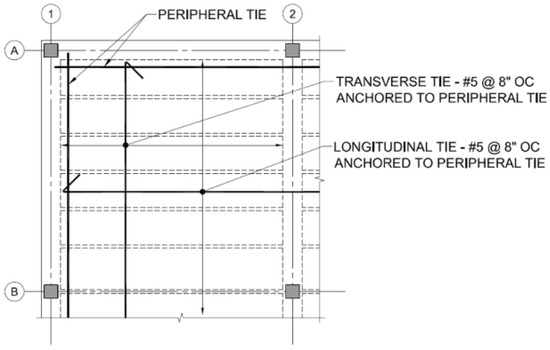
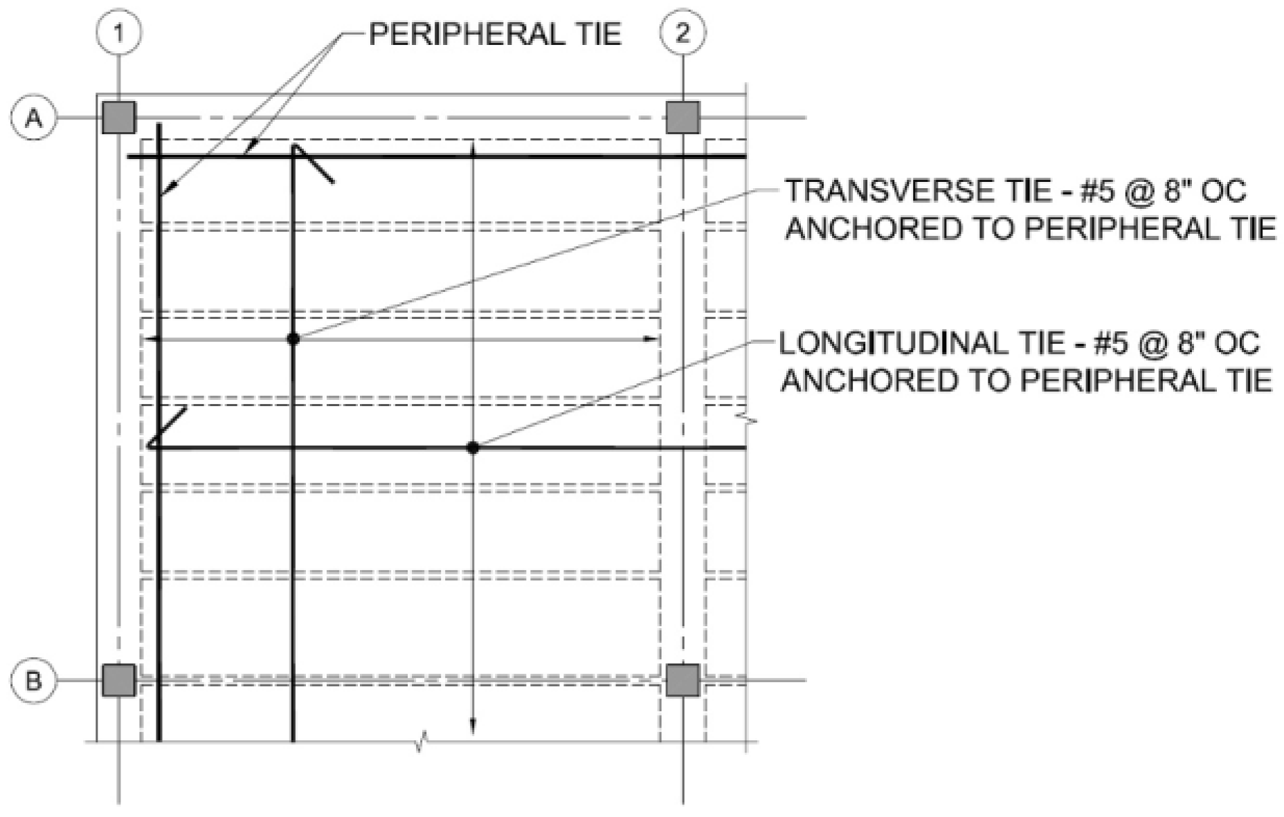
Structures are typically designed by structural engineers on the basis of conventional loading scenarios prescribed in design standards. However, during their service lives, some structures may be subjected to unexpected shock-type actions that differ from these traditional loads [22]. Such actions can cause one or more structural members to lose their load-carrying capacity. Members that have lost their capacity may subsequently trigger a chain reaction of failures, leading to a progressive collapse of the structure. To mitigate this risk, several developed countries have incorporated specific provisions related to progressive collapse into their design regulations. One such provision is the Tie-Force Method and the associated forces specified in UFC 4-023-03, shown in Figure 1.
Figure 1.
Typical layout of internal ties [23].
Following this high-profile terrorist attack, the U.S. DoD issued UFC 4-023-03 together with the GSA guidelines on progressive collapse. To date, few other developed countries have published comparable, dedicated procedures for progressive-collapse analysis.
UFC and GSA guidelines for progressive collapse likewise adopt a consequence-based framework and provide corresponding analysis procedures. Their requirements are expressed in terms of risk categories and minimum geometric limits. In particular, UFC prescribes explicit progressive-collapse design checks for buildings with at least three storeys [7]. This threshold is justified by a column-removal scenario involving at least two adjacent bays and three storeys. For buildings in higher risk categories (e.g., RC III and RC IV), AP, TF and ELR must be used in combination or in selected subsets, whereas for lower-risk buildings, it is sufficient to apply TF alone or limited AP analyses. Such risk- and method-based classifications also require that a separate accidental loading case be defined on the action side of design. From the standpoint of design loads, robustness verification is therefore generally performed under a distinct accidental load combination. In the Eurocode format [10,23], this combination can be expressed, in simplified form, as follows:
In this formulation, denotes the characteristic permanent actions, denotes the characteristic variable actions, factors represent the frequent or quasi-permanent components of the variable actions, and denotes the model accidental action. This combination defines the design gravity load level under which the structural robustness and progressive-collapse resistance are verified in the accidental design situation.
Building on these principles, most analytical procedures and research on progressive collapse are conducted with reference to UFC. In the present study, all analyses are likewise performed in accordance with UFC 4-023-03.
2.2. UFC 4-023-03 Design Guidance
Many countries have introduced definitions and general provisions on progressive collapse into their structural codes, thereby raising awareness of robustness issues. By contrast, several countries still do not provide explicit progressive-collapse provisions in their building codes, so UFC-type procedures are often adopted as an external benchmark for critical RC structures [5,13]. Following the 2001 terrorist attacks, the United States went a step further and published UFC 4-023-03, thus becoming the first country to officially codify explicit analysis and design procedures for progressive collapse [7,8]. Because UFC 4-023-03 provides a current, systematically calibrated set of AP, TF and ELR procedures that can be applied directly in everyday design practice, and has been widely adopted as a benchmark reference in the literature [7,9,11,12], it is taken in this study as the governing guidance document for progressive-collapse assessment. Specifically, UFC is adopted in this study for the definition of damage scenarios, load combinations and acceptance criteria. Section 2.3 focuses the robustness assessment on the TF provisions.
2.3. Tie-Force Method (TFM)
The TFM aims to enhance the continuity, ductility and alternative load-transfer paths of the structure by mechanically tying the load-bearing structural members together [7]. In this framework, three types of longitudinal and transverse ties are provided, together with vertical ties in columns and load-bearing walls. These are longitudinal, transverse and peripheral ties. The “tie forces” referred to herein are not the same as the transverse reinforcement (stirrups) defined in ACI 318 [24,25]. If it cannot be demonstrated that the beams, primary beams (girders) and their connections are capable of carrying the required tie forces while undergoing a rotation of 0.20 rad (≈11.3°), these forces shall instead be provided by the floor and roof system. Suitable systems for this purpose are cast-in-place concrete slabs, composite slabs, and precast floor units completed with a topping layer, reinforcement and mechanical anchorage. Composites such as FRP are not accepted unless it is demonstrated that they can satisfy the same rotation requirement; in addition, positive mechanical anchorage between the tie elements and the other load-bearing members is mandatory [7].
According to the Load and Resistance Factor Design (LRFD) approach, the design tie resistance is taken as the product of the nominal tie resistance Rn, calculated in accordance with the assumptions and requirements of the relevant material-specific standards, and the resistance reduction factor ϕ. In the LRFD approach, the design tie resistance must be greater than or equal to the required tie resistance:
where ϕRn denotes the design tie resistance, ϕ the resistance reduction factor, Rn the nominal tie resistance, and Ru the required tie resistance. The required tie resistances for framed structures and structures with load-bearing walls are given in the following subsections. When applying the TFM, several loading conditions must be taken into account, the first of which is the uniformly distributed floor load. The initial step in the tie-force calculations is to determine this floor load, which is given by Equation (3).
where denotes the floor load (lb/ft2 or kN/m2), denotes the dead load (lb/ft2 or kN/m2), and denotes the live load (lb/ft2 or kN/m2).
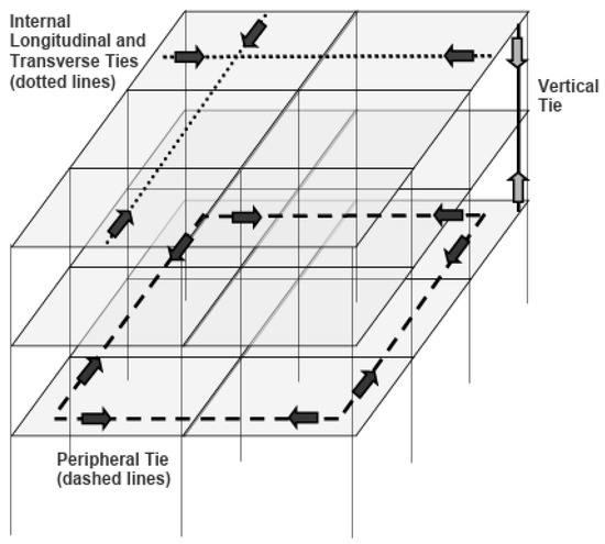
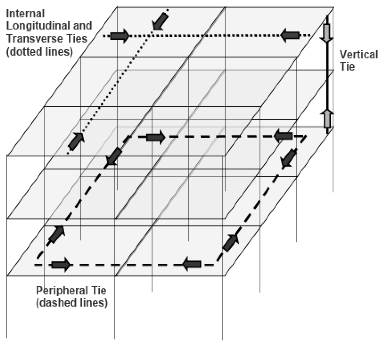
Within this method, the longitudinal and transverse tie system consists of three types of ties: longitudinal, transverse, and peripheral. In addition, vertical ties are provided in columns and load-bearing walls, and their configuration in frame construction is shown schematically in Figure 2.
Figure 2.
Tie forces in a frame structure [7].
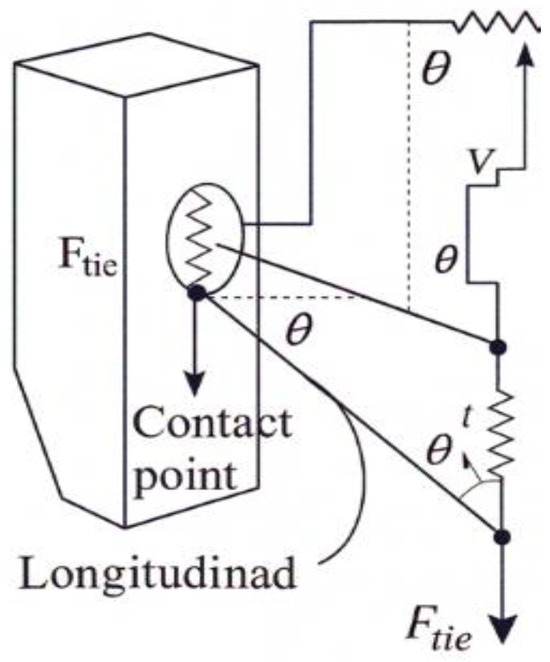
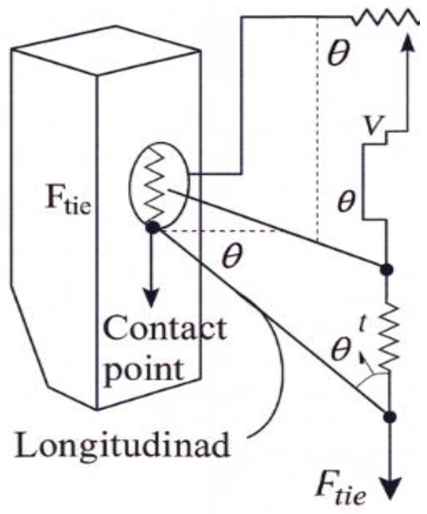
The longitudinal and transverse ties provided along each floor form a system that integrates the primary and secondary beams and other structural members from the roof down to the foundation. In the design of these internal ties, it is essential that the beams be capable, in theory, of sustaining a rotation of 0.20 rad (≈11.3°). For example, if the required longitudinal tie force is 10 k/ft (146 kN/m) and the beam spacing is 10 ft (3.05 m), the design must demonstrate that, at a rotation of 0.20 rad, the beam can resist a tensile force of 100 k (445 kN) [7]. In order to reflect the mechanical behaviour of tie forces in structural systems, an idealised connection point is schematised using spring elements, as shown in Figure 3.
Figure 3.
Mechanical modelling of tie forces [7].
With UFC 4-023-03, a new approach has been adopted and implemented in the guideline. In this approach, the internal tie forces are intended to be transmitted to the floor system so that these forces are distributed through the beams, girders and external walls. The main additions compared with the previous version are as follows:
- The requirements are defined independently of the material type.
- Provisions have been introduced for openings in the floor plane (such as stairwells, elevator shafts and atria), requiring peripheral ties to be placed around such openings.
- Additional rules have been provided to account for significant variations in loading associated with the floor plan geometry.
For transverse or longitudinal ties, the required tie force is given by
Peripheral tie forces:
is calculated as follows. Here, represents the tie force, the floor load, the spacing between the primary load-bearing elements (columns, load-bearing walls, frame systems), the façade load, and a length of 3.3 ft (1.0 m).
The integrity provided by the required vertical ties is fundamental. For this purpose, columns and load-bearing walls shall be used; each column and load-bearing wall (in one or two directions) shall be connected by vertical ties that are straight and continuous from roof level down to the lowest floor supported by the column on the foundation [7].
where represents the vertical tie force, represents the floor load, and represents the column tributary area.
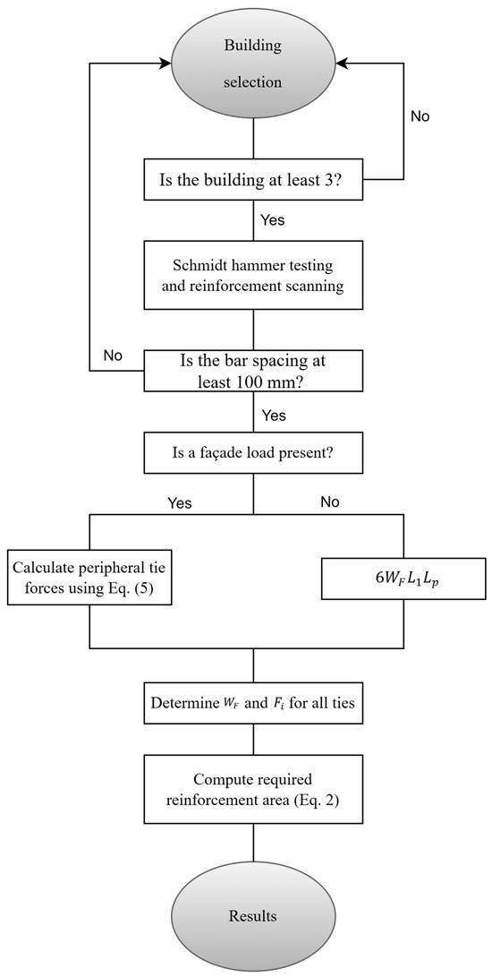
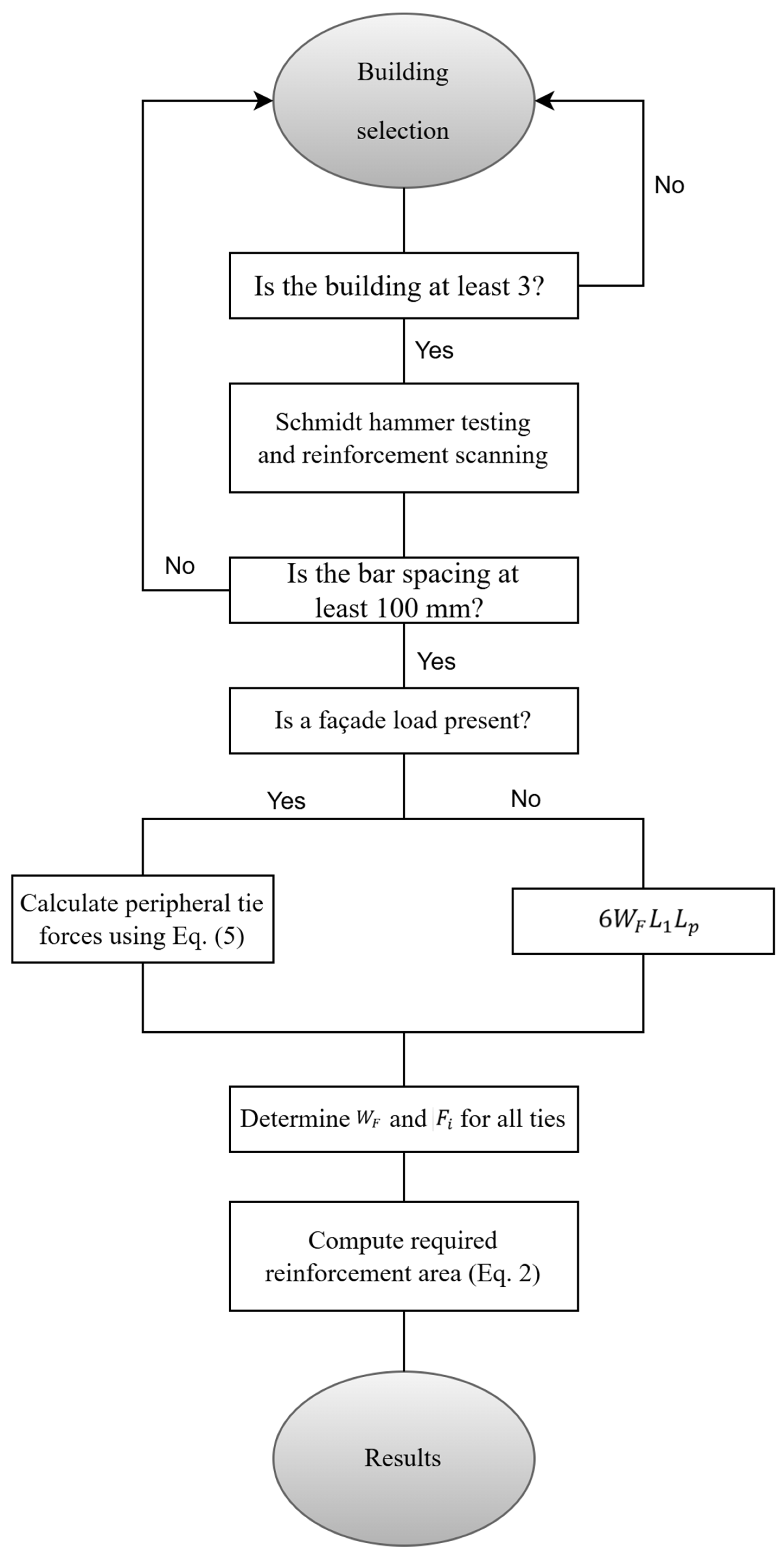
In line with the information given above, the method and working procedure adopted in this study follow a systematic workflow schematically illustrated in Figure 4.
Figure 4.
Overall workflow of the study.
Applicability and Limitations of TFM
TFM adopted in this study is not intended to directly demonstrate the alternate load path capacity against progressive collapse. Rather, it is an integrity-based approach that assesses whether member-to-member continuity and the available tie capacity satisfy minimum integrity requirements. Accordingly, TFM is more suitable for systems with a regular structural configuration, where load transfer can be reasonably represented through reinforcement continuity and where connection detailing provides adequate tensile continuity. Because the investigated buildings are typical basement-free reinforced-concrete frame residential structures, TFM is used in this study as a comparable integrity indicator and screening tool across different, relatively regular buildings. In this sense, TFM provides a rapid, consistent, and comparable first-tier assessment of structural continuity for the building types considered. Conversely, its representativeness may diminish in systems exhibiting pronounced plan/elevation irregularities; long spans or critical transfer elements (e.g., transfer girders); weak connection details; increased risk of brittle failure; and significant second-order effects or scenarios in which local damage can rapidly evolve into progressive collapse. Therefore, in such cases, TFM results should not be construed as a surrogate for alternate load path performance. They should be interpreted as a minimum adequacy check and, where necessary, be supplemented with Alternate Path-based verification analyses.
2.4. Test Equipment
In this study, a Schmidt rebound hammer was used to non-destructively determine the in situ compressive strength of concrete, while a wall-scanning (rebar detection) device was employed to identify the diameter, spacing, and layout of reinforcement in structural members. The resulting concrete strength and reinforcement data were used as input for the calculations and assessments presented in the subsequent subsections.
2.4.1. Schmidt Rebound Hammer Tests
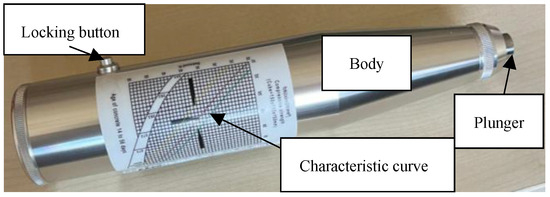
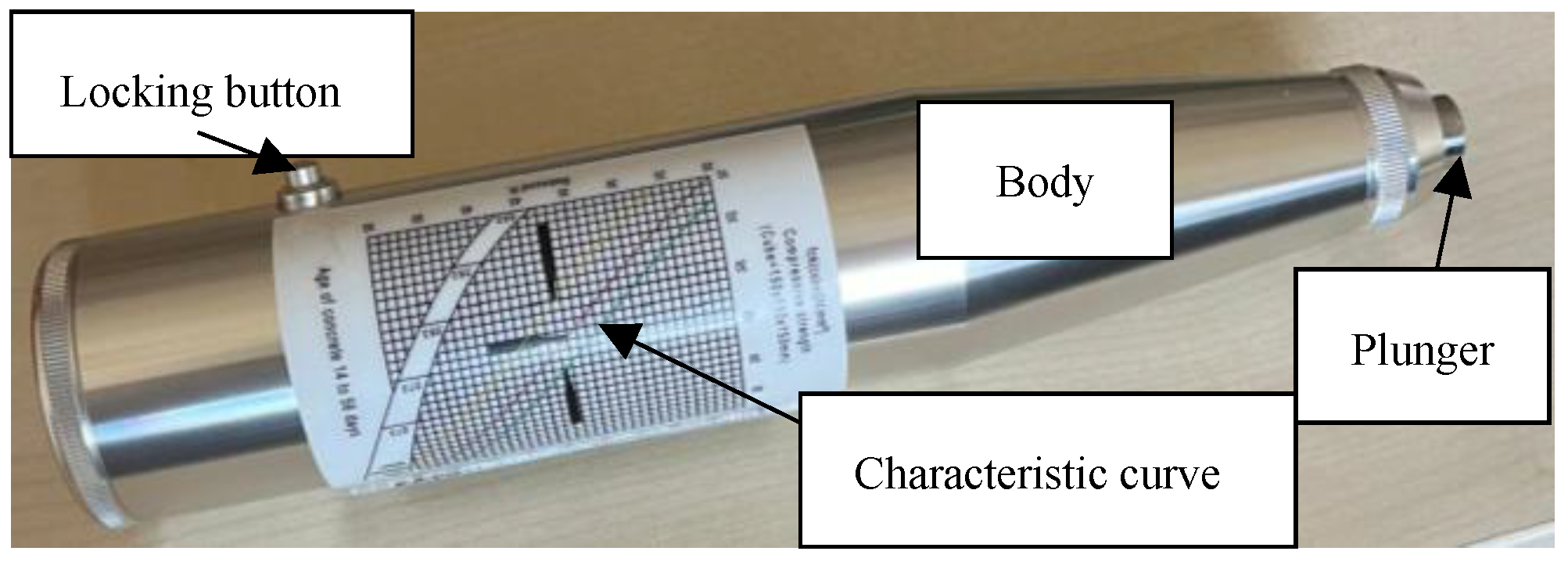
The Schmidt hammer test is a non-destructive method that indirectly evaluates the surface hardness and, consequently, the strength of a material based on the rebound value “R” obtained when a spring-driven mass impacts and rebounds from the surface. The device was developed by Ernst O. Schmidt in 1948 and was commercialised by Proceq under the name “Original Schmidt” in 1954 [26]. The Schmidt hammer is shown in Figure 5.
Figure 5.
Schmidt hammer.
In this study, the Schmidt rebound hammer was chosen as the non-destructive test method because it provides fast, low-cost and completely non-destructive measurements. Numerous experimental studies have shown that there are strong correlations, mostly with R2 > 0.9, between rebound number and compressive strength, and that the method can estimate strength with acceptable errors for structural assessment [27,28,29,30]. It is also emphasised that, when used together with a limited number of core tests, the rebound hammer is one of the effective tools for in situ strength evaluation of existing concrete structures [31].
2.4.2. Wall-Scanning (Rebar Detection) Device
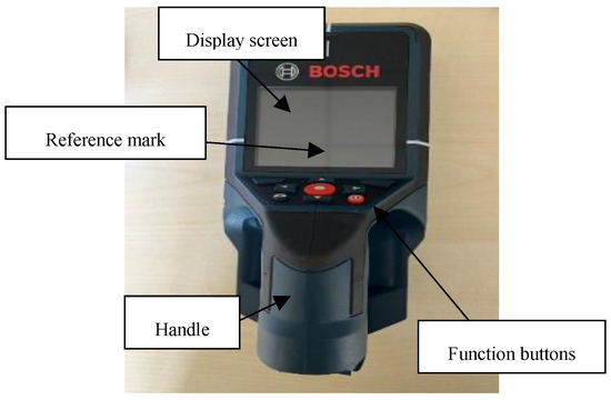
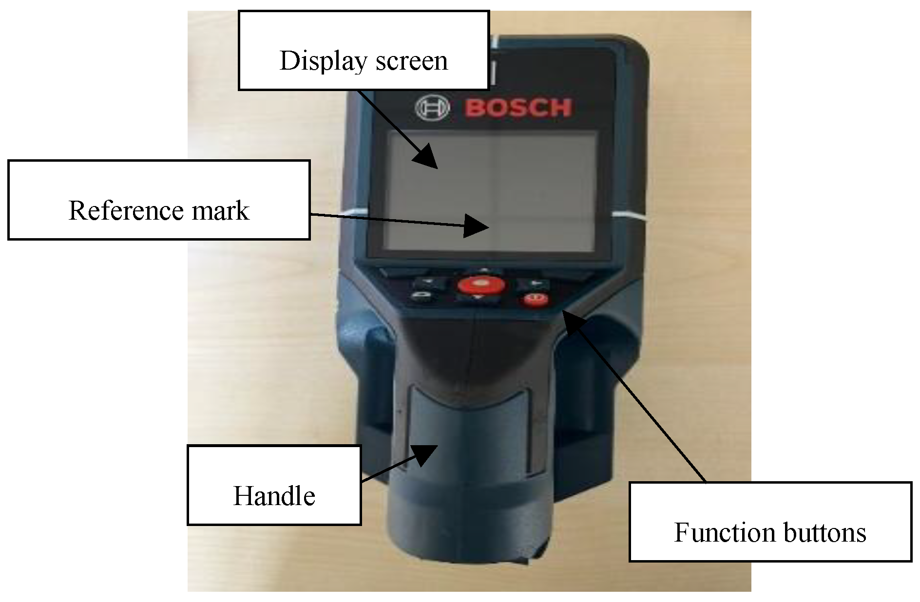
Within the scope of this study, a wall-scanning device was used to determine the reinforcement spacing and distribution in the slabs, beams, and columns of the existing buildings. By checking the bar diameters and spacings specified in the structural design drawings of each building, the Tie-Force Method analysis was applied. The wall-scanning device used in the study is shown in Figure 6, and its main technical specifications [32] are given in Table 1.
Figure 6.
The pacometer to detect the reinforcement.
Table 1.
Characteristics of pacometer.
Reinforcement layout and concrete cover were determined using a pacometer, as in previous studies that used similar devices to assess reinforcement position and cover in situ [33,34,35].
2.4.3. Buildings
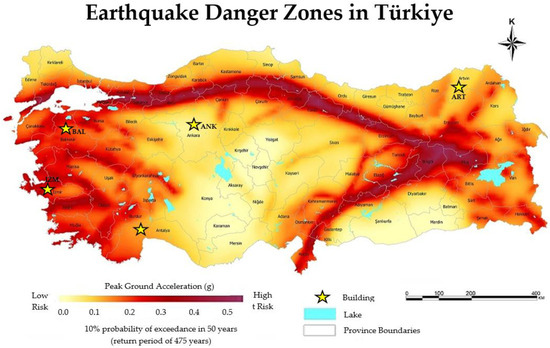
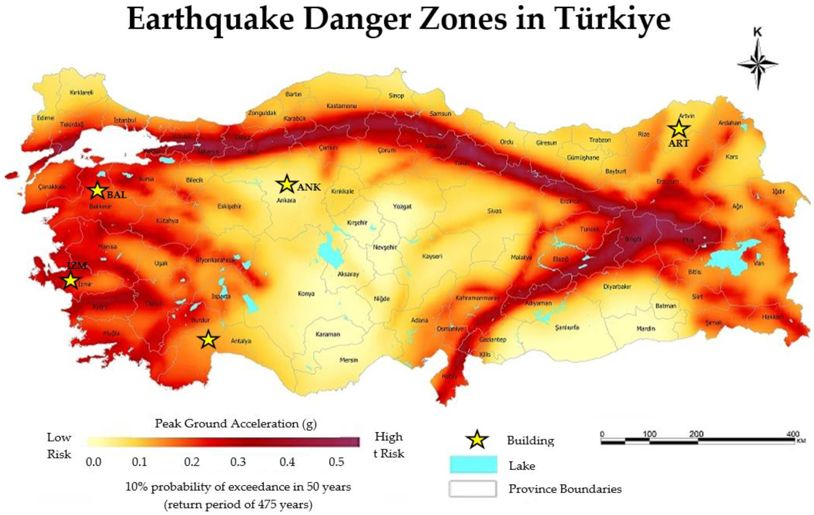
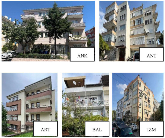
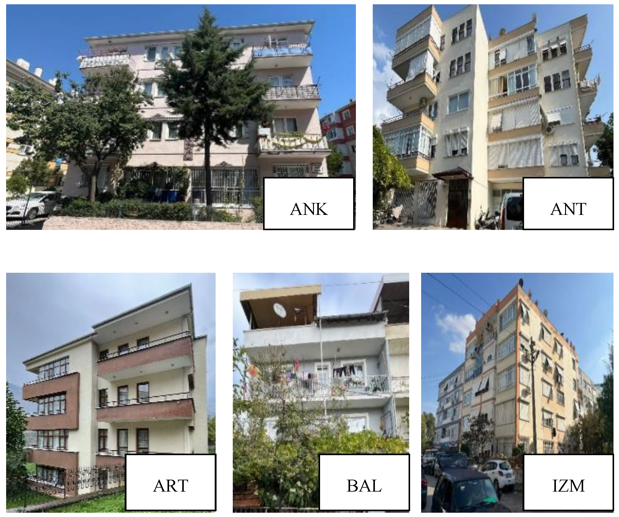
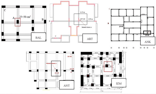
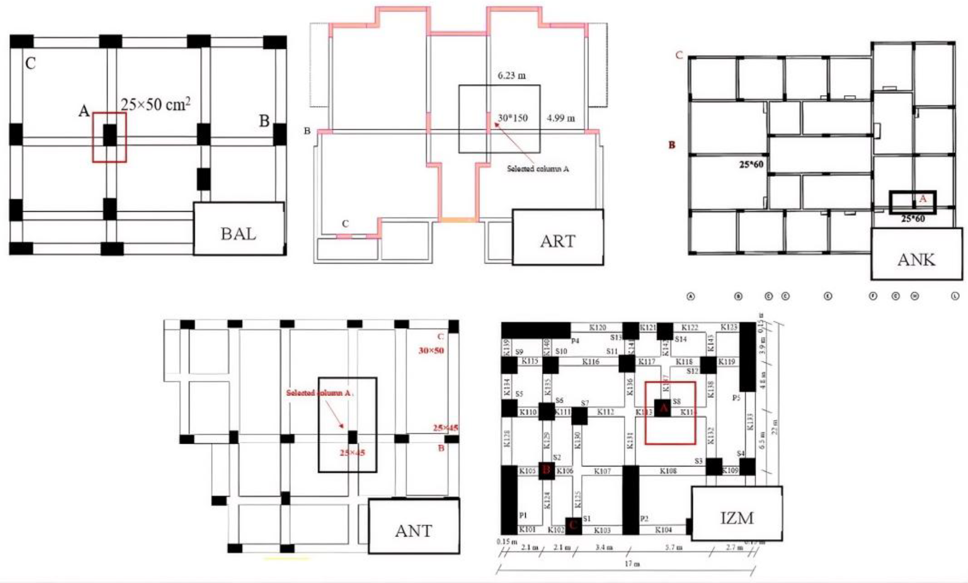
Within the scope of this study, five buildings were selected as archetypes to capture the most common layout characteristics. These buildings are located in different geographical regions and seismic zones across Türkiye, specifically in the provinces of Artvin (ART), Ankara (ANK), İzmir (IZM), Balıkesir (BAL), and Antalya (ANT), and were selected from sites exhibiting comparable topographic characteristics and similar hazard susceptibility profiles with respect to landslides, floods, and seismic activity. All of them are situated in areas with potential landslide or flood risk. The locations of the investigated buildings on the seismic hazard map [36] are shown in Figure 7, and the selected buildings are presented in Figure 8.
Figure 7.
Locations of the investigated reinforced concrete buildings on the national earthquake hazard map [36].
Figure 8.
The investigated reinforced concrete buildings.
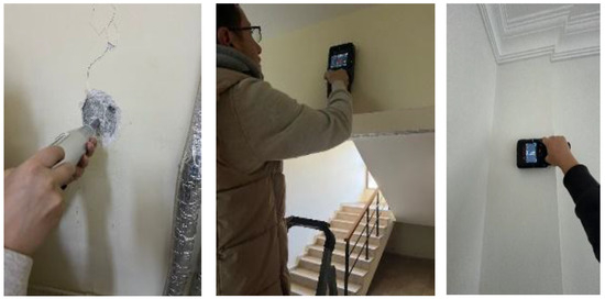
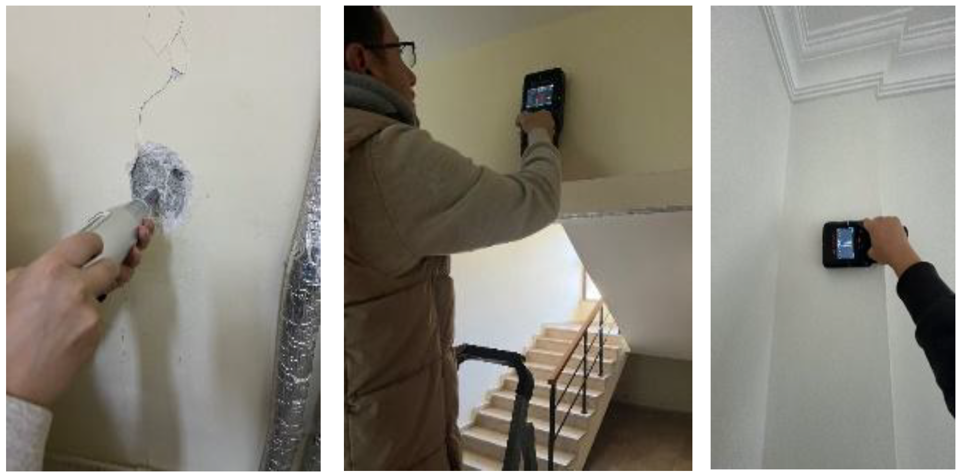
The five selected buildings are located in different seismic zones. The buildings were chosen from both low- and high-hazard regions. BAL and IZM are located in high-hazard zones, ANT is in a relatively moderate-hazard zone, and ANK and ART are in low-hazard zones. All buildings are reinforced concrete structures without basement storeys. The foundation and structural member properties of the investigated reinforced concrete buildings are summarised in Table 2, while their geometrical and design parameters are given in Table 3. The concrete and reinforcement details are presented in Table 4. The data collection procedures carried out in the selected buildings, including in situ concrete strength assessment with a Schmidt rebound hammer and detection of reinforcement using a wall scanner, are illustrated in Figure 9.
Table 2.
Foundation and structural member properties of the investigated reinforced concrete buildings.
Table 3.
Geometrical and design parameters of the investigated buildings.
Table 4.
Concrete and reinforcement details.
Figure 9.
In situ data collection in the selected buildings.
3. Results
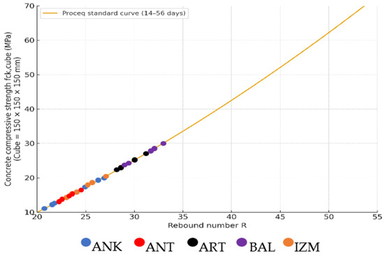
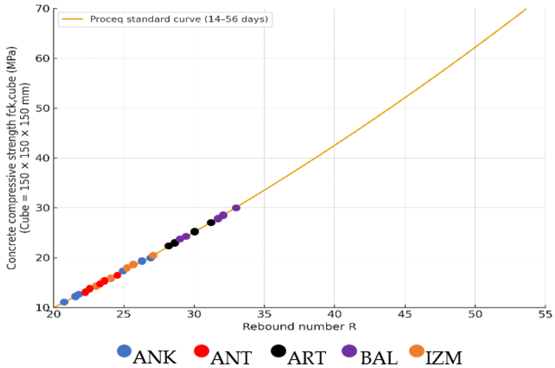
Concrete compressive strengths of beams and columns in the five selected buildings were determined using a Schmidt rebound hammer. In each building, tests were conducted at eight different locations where plaster and paint were removed to expose the bare concrete surface, and ten rebound (R) readings were taken at each location. The minimum and maximum readings at each location were discarded. Based on the remaining rebound values and the Schmidt correlation curve, the concrete compressive strengths listed in Table 4 were obtained. The representation of concrete compressive strength versus rebound number R on the Schmidt correlation curve for the five buildings is presented in Figure 10.
Figure 10.
Rebound number/compressive strength calibration curve.
Among the five buildings, BAL and ART exhibit the highest concrete compressive strengths, with very similar values of 25.40 MPa and 26.00 MPa, respectively. In contrast, ANK shows the lowest concrete strength, with a value of 14.80 MPa. The remaining two buildings, ANT and IZM, have intermediate strengths of 18.20 MPa and 17.00 MPa, respectively, as obtained from the rebound hammer tests. These differences highlight the considerable variability in in situ concrete quality within the investigated building stock.
In the investigated buildings, balconies and other rooms were considered separately. Since the imposed loads on balconies differ from those in the other functional areas (OFAs), two distinct sets of floor loads (balcony and other rooms) were calculated for buildings with balconies, whereas only one set of floor loads was determined for buildings without balconies using the relevant code equations. As façade loads are not present in the examined buildings, the exterior façade load was taken as zero in all buildings and calculations. The resulting storey loads for the five buildings are summarised in Table 5.
Table 5.
Storey loads for balconies and other functional areas.
The design storey loads are summarised in Table 5. Using the relevant code equations, the balcony floor loads WF were calculated to be in the range of 7.36–12.35 kN/m2 (ANK and ART). For the other functional areas, the calculated WF values vary between 5.86 and 10.85 kN/m2. The highest storey load is obtained for ART, while the lowest value is obtained for ANK. Since BAL and IZM do not have balconies, only a single-storey load was calculated for the “other functional areas” in these buildings. As no perimeter façade loading is present in the investigated buildings, the façade load was taken as Wc = 0 in all calculations. These design floor loads directly affect the tie-force demands, because all horizontal and vertical tie forces in UFC 4-023-03 are proportional to WF. The calculated storey loads constitute a common input parameter used in the calculations for all tie types.
For peripheral ties, using the storey loads given above, the tie force corresponding to the grid lines with the largest spans in both directions was calculated, and after applying the LRFD reduction factor of 0.75, the required peripheral tie forces for the most unfavourable tie lengths are summarised in Table 6.
Table 6.
Peripheral tie forces.
In terms of peripheral ties, Table 6 summarises the required peripheral tie forces for the most critical tie lengths along the grid lines with the largest spans in each building. The peripheral tie forces in the balcony regions are approximately 145–450 kN, whereas in the other functional areas, they reach about 630 kN and 495 kN in the X- and Y-directions, respectively. For the other functional areas, Building IZM also exhibits relatively high peripheral tie forces, on the order of 260–300 kN. By contrast, Building ANK shows the lowest peripheral tie forces for both balconies and other functional areas, with values of about 40–130 kN and 130–215 kN, respectively. In the buildings with balconies, the peripheral tie forces in the balcony strips are generally lower than, but still comparable to, those in the other functional areas and may control the design in some directions.
Table 7 presents the reinforcement ratio required, in accordance with UFC, to increase the adequacy and degree of tying of the peripheral ties.
Table 7.
Required reinforcement area for peripheral ties.
In the balcony regions, the required peripheral tie reinforcement in Building ANK is approximately 112 mm2 in the X-direction and 336 mm2 in the Y-direction, whereas in Buildings ANT and ART, these values increase to about 172–591 mm2 and 367–1139 mm2, respectively. In the other functional areas (OFAs), the required peripheral tie reinforcement increases further; the highest demands are obtained in Building ART, with approximately 1595 mm2 and 1258 mm2 in the X- and Y-directions, respectively. In Buildings BAL and IZM, which have no balconies or only recessed balconies, the required reinforcement area in the OFAs is approximately 479 and 664 mm2 in the X-direction and 425 and 757 mm2 in the Y-direction. These numerical results indicate that, in general, the other functional areas require larger peripheral tie reinforcement than the balcony regions, with the most critical conditions occurring in Buildings ART and IZM, whereas Building ANK exhibits the lowest peripheral tie-reinforcement demand.
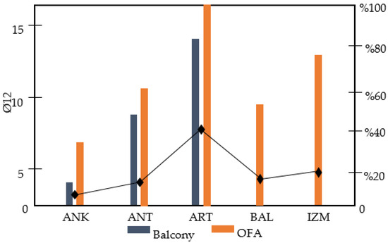
Based on the required reinforcement areas, Figure 11 presents, for both the balcony and the OFA regions, the number of Ø12 bars required and percentages for the peripheral ties in each functional space.
Figure 11.
Required Ø12 peripheral tie bars in balconies and OFAs.
Separate reinforcement calculations were performed for the balcony and OFA regions. The reinforcement demands obtained in the directions orthogonal to the global X and Y axes were combined and plotted in Figure 12. Building ART exhibits the highest demand for peripheral tie reinforcement both in the balcony spaces and in the OFAs; in the OFAs of ART, a total of 26Ø12 bars are required. In the OFAs of the remaining buildings, the required amounts are 13Ø12, 11Ø12, 9Ø12 and 7Ø12 bars for IZM, ANT, BAL and ANK, respectively. In the balcony regions, 8Ø12 and 7Ø12 bars are required in ANT and ANK, respectively. When only the OFA is considered, ART, IZM, ANT, BAL and ANK account for approximately 40%, 20%, 16%, 13% and 11% of the total 67Ø12 peripheral tie bars required.
Figure 12.
Required Ø12 longitude and transverse tie bars in balconies and OFAs.
For the longitudinal and transverse ties, using the storey loads given above, the tie forces corresponding to the grid lines with the largest spans in both directions were calculated, and the required longitudinal and transverse tie forces for the most unfavourable tie lengths are summarised in Table 8.
Table 8.
Longitudinal and transverse tie forces.
For each building, the required tie forces for the most unfavourable tie lengths along the grid lines with the largest spans are obtained. In the balcony regions, the required tie forces range from approximately 22 to 72 kN in the X-direction and from 66 to 224 kN in the Y-direction; the largest balcony tie forces occur in Building ART, whereas the lowest values are obtained in Building ANK. In the other functional areas (OFA), the tie forces increase significantly. The highest demands again occur in Building ART, reaching about 314 kN and 248 kN in the X- and Y-directions, respectively. Buildings IZM and BAL also exhibit relatively high tie forces in the OFAs, on the order of 130 kN in the X-direction and 140–150 kN in the Y-direction, whereas in Buildings ANK and ANT, these forces remain in the range of 90–110 kN in X and 67–123 kN in Y. Overall, the longitudinal and transverse tie forces in the balcony strips are lower than those in the corresponding OFA regions, indicating that the interior functional areas, particularly in Building ART, govern the tie-force design.
Table 9 presents the reinforcement ratios required, in accordance with UFC, to improve the adequacy and degree of tying of the longitudinal and transverse ties.
Table 9.
Required reinforcement area for longitudinal and transverse ties.
In the balcony regions, the required longitudinal and transverse tie reinforcement in Building ANK is about 56 mm2 in the X-direction and 168 mm2 in the Y-direction, whereas in Buildings ANT and ART, these values increase to approximately 34–183 mm2 in X and 116–569 mm2 in Y, with ART exhibiting by far the largest balcony reinforcement demand. In the OFAs, the required reinforcement areas increase substantially; the highest demands are again obtained in Building ART, with about 798 mm2 and 629 mm2 in the X- and Y-directions, respectively. In Buildings BAL and IZM, which have no balconies or only recessed balconies, the required reinforcement area in the OFAs is approximately 239–332 mm2 in the X-direction and 356–378 mm2 in the Y-direction. By contrast, Buildings ANK and ANT exhibit lower OFA demands of about 272 and 93 mm2 in X and 170 and 123 mm2 in Y, respectively. Overall, these numerical results indicate that the other functional areas require significantly larger longitudinal and transverse tie reinforcement than the balcony regions, with Building ART, followed by IZM and BAL, governing the design, whereas ANK and especially ANT exhibit the lowest reinforcement demands.
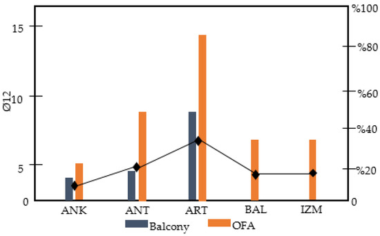
Based on the required reinforcement areas, Figure 12 presents, for both the balcony and the OFA regions, the number and percentages of Ø12 bars required for the longitudinal and transverse ties in each functional space.
Separate reinforcement calculations were performed for the balcony and OFA regions. The reinforcement demands obtained in the directions orthogonal to the global X and Y axes were combined and plotted in Figure 13. Building ART exhibits the highest demand for longitudinal and transverse tie reinforcement both in the balcony spaces and in the OFAs; in the OFAs of ART, a total of 14Ø12 bars are required. In the OFAs of the remaining buildings, the required amounts are 7Ø12, 8Ø12, 7Ø12 and 5Ø12 bars for IZM, ANT, BAL and ANK, respectively. In the balcony regions, 4Ø12 and 3Ø12 bars are required in ANT and ANK, respectively. When only the OFA is considered, ART, IZM, ANT, BAL and ANK account for approximately 34%, 17%, 20%, 17% and 12% of the total 41Ø12 longitudinal and transverse tie bars required.
Figure 13.
Columns selected for vertical tie-force calculations.
Tie deficiencies arise after damage or localised loss of a load-bearing element, when gravity loads are forced to redistribute through alternative load paths and, with increasing deflections, tensile continuity becomes critical. The slab/beam system initially transfers load to adjacent supports primarily through flexural action. As span lengths increase, internal forces and deflections grow; with larger deflections, the system partially shifts toward a membrane/catenary response, which increases the required tie tension. Consequently, in long-span configurations, the available alternative load paths are reduced, and the tie demand becomes more governing. In addition, plan eccentricity, diaphragm openings, and re-entrant plan irregularities amplify torsional effects and concentrate force flow along the perimeter, thereby increasing peripheral tie demands. As a result, the observed deficiencies are more often related to interrupted reinforcement continuity, insufficient anchorage/splice length, and limited force development/transfer capacity at connections than to a lack of reinforcement area alone. Therefore, these geometric and system parameters directly control the magnitude and severity of tie demands.
In the calculation of the vertical tie forces, for each of the five buildings, the columns shown in Figure 13 were first selected. These columns were chosen because they have the largest spans in both directions or because they are corner or edge columns. Consequently, the vertical tie forces in columns with larger tributary areas can be computed to be greater than those in the other columns.
In all buildings, three different columns were selected, denoted as columns A, B and C. The tributary areas of the columns are calculated as the product of the distances between the lines passing through the midpoints of the adjacent grid lines in each direction. Based on the calculated tributary areas, the vertical tie forces, the required reinforcement areas, and the corresponding numbers of Ø16 bars, which are more commonly used in columns, are given in Table 10.
Table 10.
Required reinforcement areas and Ø16 bar numbers.
In terms of vertical ties, Table 10 shows that the design forces in the selected columns range from about 16 to 549 kN, with the greatest demand occurring in column B of Building ART. Consistent with its larger tributary areas, Building ART also exhibits the highest required reinforcement areas, reaching approximately 1394 mm2 in column B and 857 mm2 in column A, corresponding to 7Ø16 and 5Ø16 bars, respectively. In the other buildings, the required reinforcement areas for the selected columns generally lie between about 41 and 412 mm2, and can be satisfied with 1–3Ø16 bars. Building ANK shows the lowest vertical tie demands, where a single Ø16 bar is sufficient for each of the three columns. Overall, the results indicate that vertical tie requirements are most critical in Building ART, whereas the remaining buildings can meet the calculated vertical tie forces with a relatively modest amount of additional column reinforcement.
4. Conclusions and Discussion
In this study, five reinforced concrete buildings located in the provinces of ART, ANK, BAL, IZM and ANT were investigated using the TFM in accordance with UFC 4-023-03. The peripheral, longitudinal–transverse and vertical tie requirements of the structural members were determined by means of non-destructive tests and numerical analyses. The level of structural integrity against progressive collapse of buildings constructed in different geographical regions, in different design years and with different concrete strengths was compared, and similar patterns of weaknesses were observed, particularly in the longitudinal–transverse and peripheral ties. The findings indicate that all five investigated buildings require additional reinforcement according to the TFM and point to a lack of progressive-collapse design provisions within the legacy design-code framework applicable to the investigated buildings.
- UFC 4-023-03 TFM is formulated for specific facility and function categories and corresponding protection levels, and it relies on assumptions intended to enhance continuity and ductility. The buildings examined in this study, however, were designed according to older national codes. As a result, the material strengths, reinforcement anchorage, and continuity detailing of existing reinforced concrete moment resisting frame systems may deviate from the assumptions embedded in the UFC provisions. Therefore, in this paper, the UFC TFM checks are not treated as a definitive compliance assessment for these older buildings; instead, they are used as a comparative screening criterion to identify potential deficiencies in structural robustness. Any exceedance of the UFC tie-force capacity should be interpreted in the context of the original design intent and the reinforcement detailing practices of the period. Consequently, depending on the presence or absence of specific detailing features, the screening benchmark may yield results that are either constrained or more broadly informative. For critical facilities where the consequences of collapse are severe, the tie-force findings should be complemented, where deemed necessary to strengthen alignment with current code requirements, by alternative load-path analyses to verify structural performance.
- The data obtained from non-destructive tests show that the concrete compressive strengths of the buildings range approximately between 14 MPa and 26 MPa, and that reinforcement spacing varies significantly depending on the design year and the governing code. Although the building, designed according to the 2007 Turkish seismic code (DBYBHY-2007), exhibits relatively better material quality and reinforcement continuity, this structure still does not fully meet the additional reinforcement requirements prescribed by the TFM.
- As exemplified by the cases in ART and ANT, the calculated tie forces for peripheral ties locally exceed the existing reinforcement areas in all buildings; in particular, along balcony perimeters and the boundaries of large-span rooms, more than one Ø12 bar per 1 m tie length is required. This indicates that slab edges and façade lines are critical regions in progressive-collapse scenarios.
- With respect to longitudinal and transverse ties, the tie members defined along the floor slabs are insufficient in many buildings, and the existing reinforcement does not provide the tensile steel area as required by the TFM in the most critical regions. This deficiency is more pronounced in large-span slab panels and in systems predominantly spanning in a single direction.
- According to the TFM, the required horizontal tie reinforcement is determined at each floor level by the floor load WF and the plan geometry, including span lengths, grid spacing, and the overall layout, rather than by the number of storeys. However, as the number of storeys increases, the total amount of supplemental reinforcement at the building scale increases because the same tie detailing must be implemented on more floors. For vertical ties, the roof-to-foundation continuity requirement likewise leads to an increase in the total reinforcement length and the overall retrofit scope as the number of storeys increases.
- Across all five case studies, a consistent trend is observed whereby the required tie-force demand increases with the design floor load and with plan-geometry metrics. Accordingly, ART, characterised by the largest WF values (12.35 kN/m2 for balconies and 10.85 kN/m2 for OFAs), develops the highest peripheral and in-plane tie forces, as well as the highest vertical tie force. In contrast, ANK, which has the lowest WF value (5.86 kN/m2 for OFAs), exhibits the lowest vertical tie forces.
- This comparison also substantiates the interpretation that the design era and structural layout may be more influential than the geographic region itself. Despite being located in different provinces and seismic hazard zones, the four buildings designed according to the 1975 Turkish code (ANK, ANT, BAL, and IZM) exhibit similar patterns of peripheral and in-plane tie-force deficiencies. Although ART (DBYBHY-2007) reflects relatively better material quality, it still requires a substantial level of additional tie reinforcement because its heavier floor system and larger member tributary areas increase the TFM demands. Therefore, the governing parameters appear to be code-era detailing practices together with layout- and load-related structural characteristics, rather than the geographic region itself.
- It has been found that, in order to satisfy the required tensile capacities according to the TFM, the most critical regions frequently require several additional Ø12 continuity bars in the peripheral and longitudinal–transverse ties, while the vertical tie demands in the selected columns can generally be met with up to 7 Ø16 bars.
- Within the investigated sample, buildings located in different geographical regions and exposed to different potential hazard types exhibit similar deficiencies in terms of tie requirements. In other words, design year, governing code and structural system layout appear to be more influential parameters in determining tie-force demands than the geographical location itself.
- When the vertical, longitudinal–transverse and peripheral directions are considered together, it is observed that additional reinforcement is needed more frequently in the longitudinal–transverse and peripheral ties than in the vertical ties. Therefore, the most critical area for improving resistance to progressive collapse is generally the strengthening of ties within the slab plane.
- Overall, none of the five investigated buildings is able to satisfy all tie-force requirements defined in UFC 4-023-03 with its existing reinforcement details; in each building, additional reinforcement is required for peripheral, longitudinal–transverse or vertical ties to varying extents. This finding indicates that the level of structural integrity against progressive collapse is limited in the investigated buildings and may be limited in similar residential RC frame buildings in Türkiye.
- The present assessment is entirely based on as-built field data obtained from typical residential buildings, thereby providing a reference tie-force dataset and a practical workflow that can be used as a benchmark for robustness evaluations and screening studies of similar existing RC frame buildings in Türkiye.
- It was observed that the lack of resistance to progressive collapse is mainly attributable not to insufficient vertical ties but to inadequate peripheral and internal ties within the floor diaphragm. Critical regions were identified at balconies, bays with large spans, and around discontinuities and openings. Therefore, the fundamental strengthening principle is that a structure should not be considered to have adequate integrity unless continuity of the peripheral and in-slab ties is ensured. In practice, along tie lines found to be deficient particularly along the most unfavourable grid lines, the following measures should be implemented in sequence: provide additional reinforcement to form continuous tie lines along slab edges and around balconies, and verify the feasibility of continuity and anchorage at corners; integrate additional continuity reinforcement within the slab in the governing direction to act as tension ties for large-span slabs; ensure continuous peripheral tie action around openings such as stairwells and elevator shafts; detail lap splices, construction joints, and reinforcement anchorages to reliably transfer tensile forces; and, where vertical ties are inadequate, achieve continuity from foundation to roof by column jacketing and additional longitudinal reinforcement in critical columns. After strengthening, the effectiveness of the selected interventions should be verified by recalculating the TFM requirements. If the required tie capacity is still not achieved, a more advanced assessment and, if necessary, design modification should be undertaken.
- The findings, in line with the study hypothesis, indicate that the governing deficiencies across the investigated sample occur in slab-plane ties rather than in vertical ties. Vertical tie demands are relatively modest and can be satisfied by adding a limited number of supplementary column bars.
In conclusion, a larger sample is required to draw generalisable conclusions. Within the investigated sample, the TFM assessment indicates that the investigated structural system types require additional tie reinforcement to prevent progressive collapse, and that longitudinal–transverse and peripheral ties within the slab plane constitute critical weak spots. The study demonstrates that the UFC 4-023-03 guideline can be effectively adapted to similar existing RC frame buildings in Türkiye stock and suggests that comprehensive field and analytical studies could contribute to achieving a safer and more structurally robust building inventory through larger-scale field and analytical studies. Based on these findings, the following practical design guidelines are proposed to assist designers and assessors:
- Check peripheral ties first to ensure continuous reinforcement along slab edges and around balcony perimeters.
- Prioritise in-plane ties in the direction of the largest span, as tie-force demand typically increases with span length.
- Ensure continuity along all tie lines; avoid discontinuities and explicitly verify lap splices and anchorage detailing.
- Guarantee tie continuity at corners and returns; corner discontinuities are critical weak points for perimeter integrity.
- Provide a continuous tie ring around major openings (e.g., stairs/elevators) and verify uninterrupted load paths around the opening.
- For buildings with balconies or re-entrant corners, treat the perimeter as a critical tie line and verify continuity at connections and edge segments.
- Verify vertical ties primarily for key columns (corner and edge columns, and columns with large tributary areas) and ensure continuity from roof to foundation.
- When existing capacity is insufficient, prioritise retrofit measures that improve continuity and anchorage along critical tie lines (perimeter and governing in-plane direction).
- Apply a consistent checking sequence: peripheral ties, in-plane ties, vertical ties. Deficiencies in the first two checks indicate increased vulnerability.
- Design decision rule: do not assume adequate structural integrity unless both peripheral and in-plane ties satisfy the Tie-Force Method requirements; otherwise, strengthening or further assessment should be considered.
Future work could extend the present Tie-Force-Method-based framework by incorporating alternate-path analyses and examining specific retrofit strategies for deficient tie regions, so as to quantify the improvement in progressive-collapse robustness and support the development of dedicated national design provisions.
Author Contributions
Conceptualisation, S.K. and S.T.K.; methodology, S.K.; formal analysis, S.K.; investigation, S.K.; resources, S.K.; data curation, S.K. and S.T.K.; writing—original draft preparation, S.K. and S.T.K.; writing—review and editing, S.K. and S.T.K.; visualisation, S.K. and S.T.K.; supervision, S.K.; project administration, S.K.; funding acquisition, S.K.; identification of exemplary buildings, S.T.K. All authors have read and agreed to the published version of the manuscript.
Funding
This research was supported by the Scientific Research Projects Department of Artvin Çoruh University, project number: 2025.F40.02.01.
Data Availability Statement
The original contributions presented in the study are included in the article, and further inquiries can be directed to the corresponding author.
Conflicts of Interest
The authors declare no conflicts of interest.
References
- ASCE/SEI 7-22; Minimum Design Loads and Associated Criteria for Buildings and Other Structures. American Society of Civil Engineers: Reston, VA, USA, 2022. [CrossRef] [Scilit]
- Chock, G.Y.K. Design for Tsunami Loads and Effects in the ASCE 7-16 Standard. J. Struct. Eng. 2016, 142, 04016093. [Google Scholar] [CrossRef] [Scilit]
- Griffiths, H.; Pugsley, A.G.; Saunders, O. Report of the Inquiry into the Collapse of Flats at Ronan Point, Canning Town; Her Majesty’s Stationery Office: London, UK, 1968. [Google Scholar]
- Pearson, C.; Delatte, N. Ronan Point Apartment Tower Collapse and Its Effect on Building Codes. J. Perform. Constr. Facil. 2005, 19, 172–177. [Google Scholar] [CrossRef] [Scilit]
- Nelsson, R. The Collapse of Ronan Point, 1968—In Pictures. The Guardian, 16 May 2018.
- Nakao, M. Chain Reaction Collapse of a High-Rise Apartment Due to a Gas Explosion: May 16, 1968 in Ronan Point, East London, England. In Failure Knowledge Database—100 Selected Cases; Japan Science and Technology Agency: Tokyo, Japan, n.d.; Available online: https://www.shippai.org/fkd/en/cfen/CA1000634.html (accessed on 1 December 2025).
- UFC 4-023-03; Design of Buildings to Resist Progressive Collapse. U.S. Department of Defense (DoD): Washington, DC, USA, 2024.
- U.S. General Services Administration (GSA). Alternate Path Analysis and Design Guidelines for Progressive Collapse Resistance (Revision 1); U.S. General Services Administration: Washington, DC, USA, 2016. Available online: https://www.gsa.gov/system/files/Progressive_Collapse_2016.pdf (accessed on 1 December 2025).
- Li, Y.; Lu, X.; Guan, H.; Ye, L. An Improved Tie Force Method for Progressive Collapse Resistance Design of Reinforced Concrete Frame Structures. Eng. Struct. 2011, 33, 2931–2942. [Google Scholar] [CrossRef] [Scilit]
- EN 1991-1-7; Eurocode 1—Actions on Structures—Part 1–7: General Actions—Accidental Actions. European Committee for Standardization (CEN): Brussels, Belgium, 2006.
- Izzuddin, B.A.; Sio, J. Rational Horizontal Tying Force Method for Practical Robustness Design of Building Structures. Eng. Struct. 2022, 252, 113676. [Google Scholar] [CrossRef] [Scilit]
- Sio, J.; Izzuddin, B.A.; Vlassis, A. Enhanced Rational Horizontal Tying Force Method for Practical Robustness Design. Eng. Struct. 2024, 301, 117268. [Google Scholar] [CrossRef] [Scilit]
- Mpidi Bita, H.; Tannert, T. Tie-Force Procedure for Disproportionate Collapse Prevention of CLT Platform-Type Construction. Eng. Struct. 2019, 189, 195–205. [Google Scholar] [CrossRef] [Scilit]
- Arcuri, D.; Magatelli, S.; Martinelli, P. Application of the Tying Force Method in the Design of Alternative Load Paths in Post-and-Beam Timber Structures: A Case Building. J. Build. Eng. 2023, 78, 107577. [Google Scholar] [CrossRef] [Scilit]
- Kılıçer, S. Progressive Collapse Design Procedure: Tie Force Method. In International Studies and Assessments in Civil Engineering; İskender, E., Ed.; Serüven Publishing: Istanbul, Türkiye, 2024; pp. 57–73. [Google Scholar]
- Lu, X.; Lin, K.; Li, Y.; Guan, H.; Ren, P.; Zhou, Y. Experimental Investigation of RC Beam–Slab Substructures against Progressive Collapse Subject to an Edge-Column-Removal Scenario. Eng. Struct. 2017, 149, 91–103. [Google Scholar] [CrossRef] [Scilit]
- Ren, P.; Li, Y.; Lu, X.; Guan, H.; Zhou, Y. Experimental Investigation of Progressive Collapse Resistance of One-Way Reinforced Concrete Beam–Slab Substructures under a Middle-Column-Removal Scenario. Eng. Struct. 2016, 118, 28–40. [Google Scholar] [CrossRef] [Scilit]
- Dat, P.X.; Hai, T.K. Membrane Actions of RC Slabs in Mitigating Progressive Collapse of Building Structures. Eng. Struct. 2013, 55, 107–115. [Google Scholar] [CrossRef] [Scilit]
- Alshaikh, I.M.H.; Abadel, A.A.; Sennah, K.; Nehdi, M.L.; Tuladhar, R.; Alamri, M. Progressive Collapse Resistance of RC Beam–Slab Substructures Made with Rubberized Concrete. Buildings 2022, 12, 1724. [Google Scholar] [CrossRef] [Scilit]
- Kaliszky, S.; Nédli, P.; Tornyos, Á. Progressive Collapse Analysis of Large Panel Buildings. Period. Polytech. Civ. Eng. 1985, 29, 33–38. Available online: https://pp.bme.hu/ci/article/view/3982 (accessed on 3 December 2025).
- Vértes, G. Progressive Ultimate Analysis of Buildings of Elastic–Brittle Material Exposed to Dynamic Effects. Period. Polytech. Civ. Eng. 1981, 25, 251–256. Available online: https://www.pp.bme.hu/ci/article/view/4090 (accessed on 10 December 2025).
- Kılıçer, S. Determination of the Progressive Collapse Risk of Structures Considering Soil–Structure Interaction. Ph.D. Thesis, Karadeniz Technical University, Trabzon, Türkiye, 2024. Available online: https://tez.yok.gov.tr/UlusalTezMerkez (accessed on 1 December 2025).
- UFC 4-023-03; Design of Buildings to Resist Progressive Collapse. U.S. Department of Defense (DoD): Washington, DC, USA, 2009. Available online: https://www.wbdg.org/FFC/DOD/UFC/ufc_4_023_03_2009_c4.pdf (accessed on 13 February 2026).
- ACI Committee 318. Building Code Requirements for Structural Concrete (ACI 318-19); American Concrete Institute: Farmington Hills, MI, USA, 2019. [Google Scholar]
- ACI Committee 318. Commentary on Building Code Requirements for Structural Concrete (ACI 318R-19); American Concrete Institute: Farmington Hills, MI, USA, 2019. [Google Scholar]
- Screening Eagle Technologies. Celebrating 65+ Years of Schmidt Rebound Technology; Screening Eagle Technologies: Schwerzenbach, Switzerland, n.d.; Available online: https://www.screeningeagle.com/en/inspection/65-year-history-schmidt-rebound-hammers (accessed on 27 October 2025).
- Aydin, A.; Basu, A. The Schmidt Hammer in Rock Material Characterization. Eng. Geol. 2005, 81, 1–14. [Google Scholar] [CrossRef] [Scilit]
- Kazemi, M.; Madandoust, R.; de Brito, J. Compressive Strength Assessment of Recycled Aggregate Concrete Using Schmidt Rebound Hammer and Core Testing. Constr. Build. Mater. 2019, 224, 630–638. [Google Scholar] [CrossRef] [Scilit]
- Fadiel, A.A.M.; Abu-Lebdeh, T.; Petrescu, F.I.T. Assessment of Woodcrete Using Destructive and Non-Destructive Test Methods. Materials 2022, 15, 3066. [Google Scholar] [CrossRef] [Scilit]
- Brozovsky, J.; Bodnarova, L.; Brozovsky, J., Jr. Rebound Hammer Tests of High-Strength Concrete: Effects of Internal Stress and the Shape of the Impact Area of the Test Specimens on the Measurement Results. Period. Polytech. Civ. Eng. 2019, 63, 215–221. [Google Scholar] [CrossRef] [Scilit]
- Breysse, D. Nondestructive Evaluation of Concrete Strength: An Historical Review and a New Perspective by Combining NDT Methods. Constr. Build. Mater. 2012, 33, 139–163. [Google Scholar] [CrossRef] [Scilit]
- Bosch Power Tools. Wallscanner D-Tect 200 C: Product Data Sheet; Robert Bosch GmbH: Gerlingen, Germany, 2023. [Google Scholar]
- Bueno, G.M.; Carneiro, E.R.; Ramão, A.C.; Piva, G.O.; Tutikian, B.F. Evaluation of Reinforced Concrete Structural Durability in the Post-Occupation Phase: A Case Study in Novo Hamburgo/RS. REM Int. Eng. J. 2019, 72, 9–16. [Google Scholar] [CrossRef] [Scilit]
- Araujo, A.D.; Oliveira, C.A.; Simão, T.R.S. Current Condition of the Exposed Concrete Façades Reinforcement of the Vilanova Artigas Building: Modern Architectural Heritage. Rev. IBRACON Estrut. Mater. 2021, 14, e14113. [Google Scholar] [CrossRef] [Scilit]
- Rahimijurabi, R. Analysis of Passive Magnetic Inspection Signals Using the Haar Wavelet and Asymmetric Gaussian Chirplet Model (AGCM). Master’s Thesis, University of Waterloo, Waterloo, ON, Canada, 2022. Available online: http://hdl.handle.net/10012/18136 (accessed on 5 December 2025).
- Disaster and Emergency Management Presidency (AFAD). Türkiye Deprem Tehlike Haritası [Turkey Earthquake Hazard Map] [Map]. 2018. Available online: https://www.jmo.org.tr/genel/jeoloji_harita.php?kod=9004 (accessed on 5 December 2025).
- Disaster and Emergency Management Presidency. Türkiye bina deprem yönetmeliği (TBDY 2018) [Turkish Building Earthquake Code, TBEC 2018]. Official Gazette of the Republic of Türkiye, 18 March 2018. Available online: https://webdosya.csb.gov.tr/db/yapiisleri/icerikler/tbdy_2018-20210506174126.pdf (accessed on 7 December 2025).

Disclaimer/Publisher’s Note: The statements, opinions and data contained in all publications are solely those of the individual author(s) and contributor(s) and not of MDPI and/or the editor(s). MDPI and/or the editor(s) disclaim responsibility for any injury to people or property resulting from any ideas, methods, instructions or products referred to in the content. |
© 2026 by the authors. Licensee MDPI, Basel, Switzerland. This article is an open access article distributed under the terms and conditions of the Creative Commons Attribution (CC BY) license.