Abstract
A novel corrugated steel-reinforced concrete pipe that enhances electromagnetic shielding performance compared to the conventional reinforced concrete power pipes is developed and presented in this paper. In order to investigate the pipe’s behaviour under jacking and service conditions, the critical axial compression and flexural moment distributions were represented by two separate flat segments of a circular pipe cross-section, respectively. A total of six column specimens were designed for axial compression testing, while another four beam specimens were prepared for four-point bending tests to examine the bending behaviour. Prior to testing, all specimens were subjected to standard curing, and the material properties of steel and concrete were determined via standard tests. The load versus deformation curves of column specimens, the moment versus deflection curves of beam specimens, and the corresponding failure modes were obtained from the tested specimens. It was revealed that the load-carrying capacities of the corrugated steel-reinforced concrete cross-sections were comparable to those of the conventional reinforced concrete counterparts. Advanced finite element (FE) models incorporating the mechanical properties of encased corrugated steel plates (CSPs) and the damage development of concrete were developed and were validated against the experimental failure modes and load-carrying capacities. Based on both experimental and numerical results, the load-carrying capacity of corrugated steel-reinforced concrete cross-sections was evaluated by referring to Chinese standard GB/T 11836 and American standard ASTM C76. The experimental and numerical finding can pave the way for further research and applications of this novel type of corrugated steel-reinforced concrete pipe.
1. Introduction
The increasing use of underground, large diameter electric power integrated pipe galleries has raised concerns about the electromagnetic interference from high-voltage cables on external instruments and equipment, particularly signal transceivers in widespread urban subway systems [1]. Conventional reinforced concrete pipes offer inadequate electromagnetic shielding [2], highlighting the necessity to develop a more suitable pipe for the integrated pipe galleries. Currently, corrugated steel pipes [3,4] and reinforced concrete pipes with inner steel tube lining [5] are employed for electromagnetic shielding. While the installation of corrugated steel pipes requires open excavation, which involves a large amount of earthwork allocation and causes interruption to ground traffic, the reinforced concrete pipes with inner steel tube lining led to considerably higher material cost.
To address these challenges, a novel corrugated steel-reinforced concrete pipe was proposed [6]. As illustrated in Figure 1, the pipe skeleton consists of a circular steel tube with rectangular corrugations, outer longitudinal rebars, and an inner reinforcement cage. It is expected that this new pipe can be capable of providing electromagnetic shielding and be suitable for pipe jacking construction [7]. The thin-walled corrugated steel tube, known for its excellent out-of-plane stiffness [8,9] is intended to replace the outer circumferential rebars. The focus of this paper is to investigate the structural mechanical behaviour of this novel corrugated steel-reinforced concrete pipe, which is the key to its engineering application and structural design.
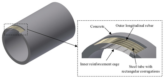
Figure 1.
Composition of novel corrugated steel-reinforced concrete pipe.
Composite corrugated steel plates (CSPs) and concrete structures have been extensively studied, with numerous experimental, numerical, and analytical studies on the behaviour of corrugated steel–concrete cross-sections [10]. Early studies included the three-dimensional concrete-lined CSP shelter proposed by Liu [11] in 2001. Other configurations involving interlocking two CSPs and infilling with concrete could enhance the load-carrying capacity and the bending stiffness [12,13,14]. The favourable stiffness and strength of CSPs have led to their use as infill plates in steel plate shear walls to improve the hysteresis behaviour [15,16,17,18,19]. Moreover, corrugated web steel beams exhibited excellent strength and local stability [20] and would be suitable for composite beams. An experimental study reported by Elamary et al. [21] and analytical work presented by Wu et al. [22] have explored the behaviour of composite reinforced-concrete–steel beams with corrugated webs. Quantitative analysis of the shear-bending interaction in such composite members and predictive models for construction-stage deflection based on neural networks have also been developed [23,24].
The CSPs have also been used to replace the straight steel plates in concrete-filled steel tube columns to enhance concrete confinement [25,26,27,28,29,30,31], benefiting from an improved mechanical bond due to their fold shape [32,33]. Shear connectors, such as studs or long bolts, have been introduced to improve the interaction between CSPs and concrete [34,35]. Systematic push-out tests have established bond–slip constitutive models and design formulas for stud-reinforced CSP–concrete interfaces [36]. CSP-reinforced concrete arches, where concrete was placed atop a CSP arch with welded rebars, have been proposed [37]. While the existing research has examined CSPs in walls, beams, columns, and arches and focused on the steel–concrete bonding and confinement, the application of CSPs within concrete for pipe structures remains unexplored. This study aims to address the gap by investigating the structural behaviour of corrugated steel-reinforced concrete pipes.
To simulate the loading conditions experienced by a large diameter of corrugated steel-reinforced concrete pipes, both column and beam specimens were designed to represent axial compression and bending, respectively. Six column specimens and four beam specimens were fabricated and tested to failure, and the load-carrying behaviour and failure modes were obtained. Parallel numerical modelling was carried out to further explore the structural behaviour of the corrugated steel-reinforced concrete specimens. The accuracy of the developed finite element (FE) models was validated against the experimental results. By studying the axial compression and bending behaviour of corrugated steel-reinforced concrete cross-sections, the underlying mechanism of CSP–concrete composite structures can be clarified. This research is of great importance for promoting the applications of corrugated steel-reinforced concrete pipes.
2. Experimental Study on Column and Beam Specimens
2.1. Design and Fabrication of Specimens
The pipe jacking process usually adopts a number of hydraulic jacks to enable the progressive installation of pipes. The end section of the pipe can be assumed to be under axial compression, whereas the underground pipe during the service state is subjected to external soil pressure, as shown in Figure 2. Given the large pipe outer diameter equalling 3600 mm and the prohibitive cost of full-scale testing, structural segments of the pipe cross-section were selected for this study. Two types of flat segments were designed to represent the axial compression and bending condition in the pipe cross-section, respectively.
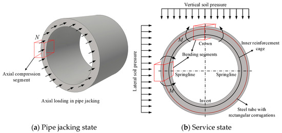
Figure 2.
Typical loading conditions of a pipe.
A rectangular corrugation of 60 × 15 mm was adopted for the circumferential stirrup in the present investigation following the guidelines set out in the standard for conventional reinforced concrete pipes GB/T 11836 [38], wherein the half-wavelength d and corrugation depth h are equal to 60 mm and 15 mm, respectively. According to the provisions in Chinese code GB 50017 [39], the thickness t of CSPs can be determined by
in which As is the equivalent cross-sectional area of CSP, and l is the unfolded length of CSP. Based on Equation (1), the thickness of a CSP was taken as 1.8 mm. The geometric shapes and dimensions of the CSPs are shown in Figure 3a.
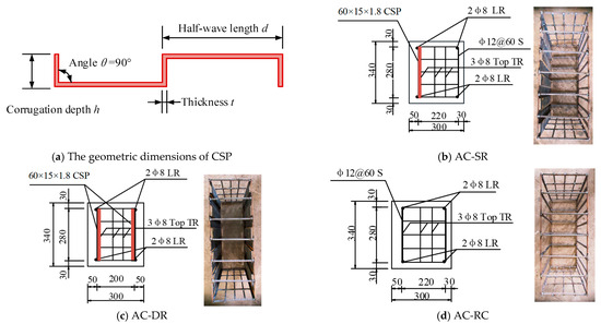
Figure 3.
Schematic diagrams of CSP and configuration details of column specimens (mm).
A total of six corrugated steel-reinforced concrete column specimens were designed and fabricated, including two single-layer rectangular corrugated steel-reinforced concrete specimens, two double-layer rectangular corrugated steel-reinforced concrete specimens, and another two conventional reinforced concrete specimens, which were denoted as AC-SR, AC-DR, and AC-RC, respectively. The details and photos of the steel skeletons of the three types of column specimens are presented in Figure 3b–d, respectively. The geometric dimensions (L × H × B) of column specimens are 680 × 340 × 300 mm. Concrete in grade C50 with fine aggregates was used for all specimens. Steel rebars in grade HRB400 were adopted for longitudinal reinforcements and high-strength steel wire for transverse reinforcements and stirrups, which was denoted as LR, TR, and S in Figure 3, espectively.
Meanwhile, four beam specimens were designed and fabricated for the four-point bending tests, including three corrugated steel-reinforced concrete specimens and one conventional reinforced concrete specimen, which were denoted as FP-SR1 (single-layer CSP at the top), FP-SR2 (single-layer CSP at the bottom), FP-DR (double-layer CSPs), and FP-RC in Figure 4a–c, respectively. The geometric dimensions of the beam specimen (L × H × B) were 2600 × 300 × 300 mm. The reinforcement areas of the specimens are summarised in Table 1 and Table 2, and the geometric and configuration details of all specimens are summarised in Table 3.
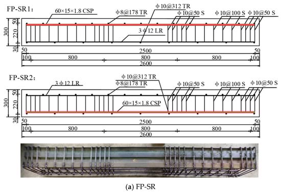
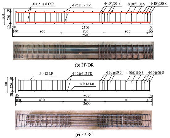
Figure 4.
Geometric and configuration details of beam specimens (mm).

Table 1.
The reinforcement areas of column specimens.
Table 2.
The reinforcement areas of beam specimens.
Table 3.
Grouping and dimension parameters of column and beam specimens.
Several uniaxial strain gauges were arranged along the centreline of the longitudinal rebar and rectangular CSP of the column and beam specimens before pouring concrete. Specifically, as shown in Figure 5a, the layout of strain gauges for column specimens was as follows: two strain gauges were attached on the flat parts of the CSP, and four strain gauges were placed at the mid-height of each longitudinal reinforcement. For beam specimens, as shown in Figure 5b, the specific arrangement layout scheme is as follows: A total of six strain gauges were arranged at the midpoint of each longitudinal reinforcement of the FP-RC specimen, a total of four strain gauge were arranged at the wide and narrow edge of the CSP for FP-SR specimen, and a total of three strain gauge were arranged at the midpoint of reinforcement. For FP-DR, the layout scheme of the strain gages on CSP was consistent with FP-SR.
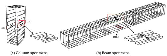
Figure 5.
Diagram of strain gauge layout on column and beam specimens.
2.2. Material Properties of Concrete and Steel
The strengths of the C50 concrete were acquired in accordance with provisions in GB/T 50081 [40]. Three standard concrete cubes with a width of 150 mm were prepared parallel to the casting of column and beam specimens, followed by the standard curing method for 28 days. The standard concrete cubes were tested under axial compression using a 3000 kN hydraulic testing machine. The average cube strength fcu,k was calculated to be 68.6 MPa, and the standard value of axial compressive strength fck was equal to 50.4 MPa.
Standard tensile coupons were machined from the CSPs in grade Q235, the locations of which are shown in Figure 6. It can be noted that the tensile coupons were extracted from both the flat region (CSP-WE and CSP-NE) and the corner region (CSP-RA). Tensile coupon tests were conducted to determine the material properties using a 300 kN capacity universal testing machine. Meanwhile, tensile coupons for the steel rebars in three different diameters—8 mm, 10 mm, and 12 mm—with the same length of 50 cm that were marked as RB-8, RB-10, and RB-12, respectively, were also prepared. Three repeated coupons were tested for each case involving those from CSPs and rebars.
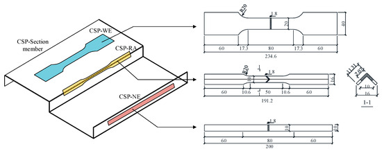
Figure 6.
Locations of tensile coupons of CSP.
The obtained full test stress–strain curves from coupons of CSPs and rebars are plotted in Figure 7. It can be seen that the material properties of coupons from the two flat parts of CSPs are close to each other, while the coupons from the corner region of CSPs exhibit a considerably higher yield strength but clearly decreased ductility due to the cold working effect. The material properties of the rebars are rather different from those of the CSPs, and the absence of a yielding plateau can be noted. The rebar with an 8 mm diameter displays the highest strength but with the lowest ductility. The average values of the experimentally determined material properties of the CSP and the steel rebars were summarised in Table 4, where E0 is the Young’s modulus, v is the Poisson’s ratio, fy is the yield strength, fu is the tensile strength, and εf is the plastic strain at fracture.
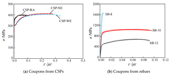
Figure 7.
Stress–strain curves of CSPs and rebars.
Table 4.
Material properties of CSP and steel rebars.
2.3. Axial Compression Tests on Column Specimens
The adopted test set-up for column specimens is shown in Figure 8, and the column specimens were tested under axial compression using a 30,000 kN compression testing machine with an electro-hydraulic servo controlling system. Each column specimen was supported by spherical hinges at both ends. Prior to testing, an initial loading of 30 kN load was applied to each column specimen to ensure the working status of the data acquisition system. The shortening deformation of each tested specimen was recorded by two symmetrically installed linear variable displacement transducers (LVDTs).
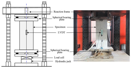
Figure 8.
Axial compression test set-up.
In accordance with GB/T 50152 [41], the testing process was initially carried out with the load control, and the loading rate was set to 1 kN/s until the end of the elastic stage. Subsequently, it was switched to displacement control with a loading rate of 0.1 mm/min, and the loading continued until reaching a clear drop of the load value. The axial compression load, end shortening deformation, and the strain development were all continuously recorded throughout the tests.
2.4. Four-Point Bending Test on Beam Specimens
The test set-up for the four-point bending tests is illustrated in Figure 9. By means of a 2000 kN capacity hydraulic actuator and a rigid distributive girder, each beam specimen was subjected to four-point bending, resulting in a pure bending effect on the central part with a length of 1200 mm. Simply supported boundary conditions for the beam specimens were achieved by a combination of hinge and roller supports at the beam ends. A total of five LVDTs were placed to monitor the vertical deflection at mid-span, two other quarter points, and the two end supports for each specimen.
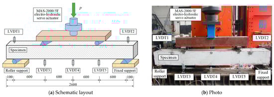
Figure 9.
Four-point bending test set-up.
The vertical load P was applied and controlled by an electro-servo controlling system. A total of ten load steps were prescribed until reaching 80% of the design load, during which the concrete cracks appearing at each load step were spotted. The displacement control method was employed afterwards, and a loading speed of 1 mm/min was maintained until reaching a clear drop in the load value (close to 85% of the peak value) or significant vertical deflection.
3. Discussion of Test Results
3.1. Axial Compression Test Results
3.1.1. Failure Mode of Column Specimens
Typical failure modes of tested column specimens under axial compression are shown in Figure 10. During testing, crack initiation and propagation was observed. For the specimens in group AC-SR, as shown in Figure 10a, no obvious cracks could be spotted from the surfaces of the specimen prior to reaching 70% of the design load, beyond which the very first crack initiated on the side exposing the CSP–concrete interface. Other small cracks also occurred with the increasing axial load, and they propagated in the vertical direction towards the top surface of column specimens. When the axial load reached 90% of the design load, the tested column displayed one major vertical crack, accompanied by the considerable increase in the end-shortening deformation. A sudden decline in the axial load after reaching the peak load value was obtained once the vertical cracks penetrated through the column length. The recorded load-carrying capacities of the two specimens in this group, AC-SR-1 and AC-SR-2, were 4041 kN and 4052 kN, respectively. Similarly, for the specimens in group AC-DR, two major vertical cracks appeared in the concrete on both sides, exposing the CSP–concrete interface, as shown in Figure 10b, and this can be attributed to the fact that two CSPs were introduced into the specimens, resulting in two CSP–concrete interfaces failing. The obtained load-carrying capacities were equal to 3802 kN and 3882 kN for specimens AC-DR-1 and AC-DR-2, respectively. It is worth noting that the CSP–concrete interface remained intact after the failure of specimens, indicating a satisfactory bonding performance between CSP and concrete, as shown in Figure 11.
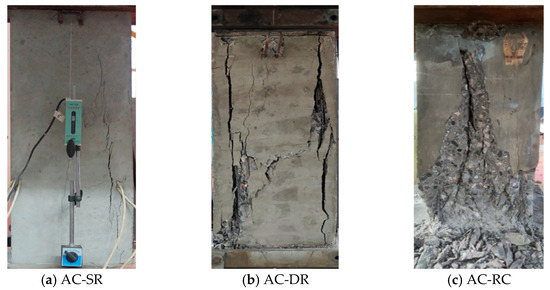
Figure 10.
Typical failure modes of column specimens.
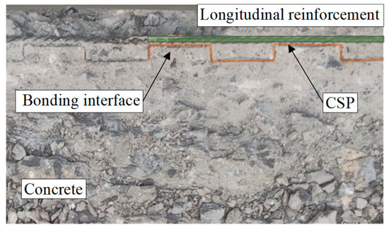
Figure 11.
The bonding interface between CSP and concrete.
Moreover, for the specimens in group AC-RC, the failure mode was rather different to those obtained in the previous two specimen groups, as shown in Figure 10c. When the axial load reached 70% of the design load, concrete cracks appeared at the corners of the column specimens. After reaching the peak load, a clear drop in the load value was noted, together with the expanding of concrete and buckling of rebars, which led to the rapid growth of vertical cracks in the middle part and the collapse of the specimen. The obtained load-carrying capacities were 4072 kN and 3446 kN for specimens AC-RC-1 and AC-RC-2, respectively. It should be noted that the failure mode of AC-RC-2 was local concrete crushing at corners, which may be caused by poor curing, resulting in the lower load-carrying capacity of AC-RC-2.
3.1.2. Load–Deformation Curves and Strain Distributions of Column Specimens
The load–deformation (F-Δ) curves are shown in Figure 12. The peak loads and displacements of the specimen are listed in Table 5. The development of deformation displayed linear increase with increasing axial load until the occurrence of cracking in concrete, beyond which, a much higher rate of increase in deformation was recorded. The initial stiffness values of specimen groups AC-SR and AC-DR were clearly higher than those of the group AC-RC, while the ultimate load-carrying capacity of the tested specimens were close to each other. The results show that the introduction of CSP have little influence on the axial load-carrying behaviour of the cross-sections and, in fact, it has a detrimental effect on the ultimate bearing capacity. Moreover, the stiffness values of corrugated steel-reinforced concrete specimens were somewhat higher than those of the ordinary reinforced concrete ones, which can be attributed to the greater stiffness of CSP than steel rebars.
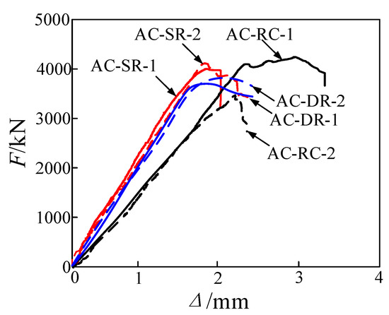
Figure 12.
Load–deformation curves of column specimens.
Table 5.
Comparison of FE results and test results of axial compression specimens.
The axial load versus recorded strains on the CSPs and steel rebars were plotted in Figure 13. For specimens in group AC-RC, as shown in Figure 13a, the strains of the four measure points exhibited similar trends, and due to the high yield strength of rebars, the strain of the rebars had not yet reached the yield strain when the specimens experienced failure. For specimens in group AC-SR and AC-DR, as shown in Figure 13b,c, the strain values of partial measuring points on the CSP increased continuously with the increase in load, while other measured points on the CSP exhibited zig zagging and small strains before the peak load. This phenomenon can be explained by the existence of the “accordion effect” of CSP, indicating that the CSP cannot fully utilise the strength under axial compression. It is worth mentioning that the strain of partial measuring points presented obvious reversal points due to the CSP tending to be flattened under the load, indicating that there exists a superior mechanical interlocking between CSP and concrete. The strain reversal phenomenon of CSP under axial compression is a direct manifestation of the excellent mechanical interlocking between CSP and concrete, which is the core of the composite action of CSRCPs. The rectangular corrugation of 60 × 15 mm makes the concrete form a “tenon-mortise structure” with the CSP, which restricts the lateral deformation of CSP under compression and avoids the interface slip between CSP and concrete. This phenomenon is consistent with the multi-scale deformation mechanism analysis of composite structures proposed by Tao and Nie [42], who pointed out that the mechanical interaction between steel and concrete components can lead to uneven strain distribution and local strain reversal, which further verifies the reliability of the test results.
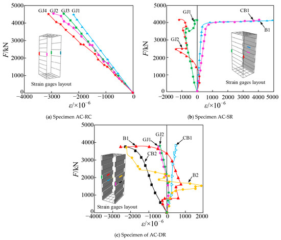
Figure 13.
Load–axial strain curves from axial compression specimens.
3.2. Four-Point Bending Test Results
3.2.1. Failure Mode of Beam Specimens
Figure 14 presents the typical failure modes of beam specimens, which could be categorised into two types: Mode 1—yield failure of longitudinal tensile rebars, evidenced by multiple, uniformly distributed cracks at the bottom of the beam (see Figure 14a,b); Mode 2—yield failure of CSP, indicated by a sparse, heterogeneous crack distribution at the bottom of the beam (see Figure 14c,d). For specimen FP-RC, the initial cracks in the vertical direction appeared at mid-span, accompanied by increasing deflection. The number and length of vertical cracks grew with continuously increasing loading application. After reaching the peak load, the specimen experienced significant bending deformation, with a few oblique cracks developed close to the end supports. The final failure of the specimen resulted from the collapse of concrete in the compression zone. For specimen FP-SR2, only a few vertical cracks with relatively larger width occurred at the pure bending part, which can be attributed to the introduction of CSPs. It can also be noted that the specimen FP-SR1 displays a similar distribution of cracks and failure mode with the specimen FP-RC, while the crack distribution of FP-SR2 is close to that of FP-DR. This can be explained by the fact that, for both FP-RC and FP-SR1 specimens, the steel rebars were placed at the bottom layer, while for FP-SR2 and FP-DR specimens, the CSPs were placed at the bottom of the cross-section.
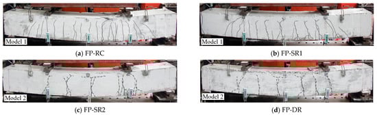
Figure 14.
Typical failure modes of beam specimens.
The different failure modes of beam specimens are closely related to the arrangement position of CSP, and this also exposes the bending performance weak point of CSRCPs: when CSP is arranged in the tensile zone, the failure is controlled by the yield of CSP (Q235) with low yield strength, resulting in a 33~34% reduction in the ultimate bending moment compared with the specimens with steel rebars in the tensile zone (FP-RC, FP-SR1). In engineering design, it is recommended to arrange high-strength steel rebars in the tensile zone of the crown cross-section of CSRCPs and match with the CSP in the compression zone to give full play to the advantages of CSP in stiffness and steel rebars in tensile strength.
3.2.2. Moment–Mid-Span Deflection Curves and Strain Distributions of Beam Specimens
The bending moment–mid-span deflection (M–f) curves of the four beam specimens were plotted and are shown in Figure 15, wherein the critical moment corresponding to the cracking Mcr of the specimens is marked by a small hollow circle, while the ultimate bending moment Mu is marked by a solid dot. All specimens experienced three stages, including the elastic stage, damage development stage, and failure stage. In the elastic stage, the M-f curves exhibited a linear relationship, and the curves of the four specimens were close to each other, indicating that the initial stiffness and Mcr values of the four specimens agreed well with each other. In the damage development stage, the cracking process led to a reduction in the stiffness of the four specimens. Before reaching the ultimate load, the beam specimens experienced a lengthy stage of plastic development, exhibiting significant ductility. The obtained test results are summarised in Table 6. The Mu values of the two specimens, FP-DR and FP-SR2, are equal to 49.11 and 49.65 kN·m, respectively, while those of the other two specimens, FP-RC and FP-SR1, display much higher values due to the introduction of high-strength steel rebars, which are 74.37 and 77.31 kN·m, respectively. In the failure stage, the CSPs at the tensile zone of the beam underwent significant plastic deformation, resulting in a further reduction in stiffness and faster development of deflection at mid-span.
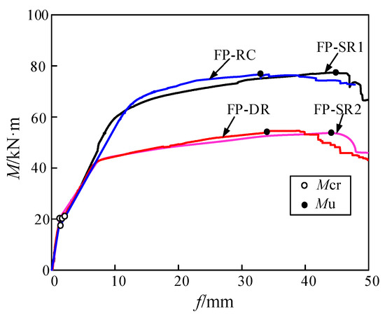
Figure 15.
Moment–deflection curves of bending specimens.
Table 6.
Comparison of FE results and test results of bending specimens.
Moreover, the recorded strain development of CSPs and steel rebars in the tested beam specimens were plotted against the applied bending moment, as shown in Figure 16. For specimens FP-RC and FP-SR1, the strain development of longitudinal rebars at the bottom (DJ1, DJ2, and DJ3) exhibited similar overall trends, and the rebars experienced complete yielding prior to reaching the ultimate bending moment; the rebars (UJ1, UJ2) of FP-RC or CSP (B1, B2, CB1, and CB2) of FP-SR1 at the top of the cross-section remained in an elastic state with relatively small compression strains throughout the testing process. For specimens FP-SR2 and FP-DR, the CSP in the tensile zone exhibited gradual yielding behaviour with an increasing bending moment while the upper rebars of FP-SR2 and the top layer CSP of FP-DR experienced smaller strains due to the contribution from the concrete in the compression.
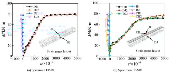
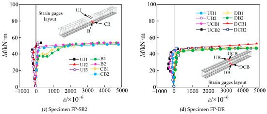
Figure 16.
Moment–strain curves of beam specimens.
4. Numerical Simulations of Axial Compression and Bending Behaviour
4.1. Development of FE Models
Numerical models for simulating the axial compression and bending behaviour of corrugated steel-reinforced concrete cross-sections were developed using the general purpose FE software package ABAQUS 2024. Combined with the classic numerical modelling framework for composite structures proposed by Tao and Nie [43], which emphasises the rationality of element-type selection, section discretization, and material hysteretic law definition for composite structural members, three individual parts including the concrete, CSP, and rebars were separately created and were assembled together. The concrete was meshed with the eight-node linear continuum solid element with reduced integration—C3D8R—and the CSP was meshed by the quadrilateral shell element S4R in view of the thin-walled characteristics, while the meshing of the rebars was implemented by the truss element T3D2. A separate mesh convergence study was carried out to acquire suitable element size configuration with a satisfactory balance between accuracy and computational efficiency. Take the FE model of specimen FP-SR1 as an example, and five different mesh size (n = 1~5) combinations with the corresponding total numbers of elements were established, as shown in Figure 17. The general element sizes for the concrete, CSP, and rebar were taken as 30, 20, and 10 mm, respectively. Hence, the total numbers of elements for specimens FP-SR1 are equal to 19,726. In a more refined mesh, with the element sizes reduced to one-half of the previous values, the improvement of accuracy in the calculation results was below 0.2%, verifying the good performance of this selected combination of mesh sizes.
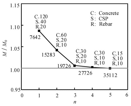
Figure 17.
Effect of element mesh size on FE results.
The constitutive relationship of CSP can be determined according to the tensile test results reported in Section 2.2. The engineering stress–strain curves were converted to true stress versus logarithmic plastic strain curves prior to input into FE models, and the nonlinear material behaviour was modelled by adopting the standard von Mises yield criterion with isotropic hardening. The strength enhancement region in the vicinity of each corner is taken as the area of the corner radius of 2t, where t is the plate thickness (t = 1.8 mm). Considering the strength degradation and damage development of concrete [44], a concrete damage plasticity model was used to simulate the tensile cracking and compression damage of concrete in accordance with GB50010 [45]. Poisson’s ratio was 0.2, the dilation angle was equal to 38°, the eccentricity was taken as 0.1, the ratio of concrete strength under biaxial equal compression over uniaxial strength fb0/fc0 was 1.16, the invariant stress ratio K was 0.6667, the viscosity parameter was 0.001, and the damage factor could be taken from Ref. [46]. The ideal elastic–plastic constitutive model was adopted for the rebars, and Young’s modulus and Poisson’s ratio were set to be 210 GPa and 0.3, respectively.
The interaction behaviour between the concrete, CSP, and steel rebars played an important role in the structural performances of corrugated steel-reinforced concrete cross-sections, which were carefully prescribed in the FE models. By referring to the contact relationship between CSP and concrete, a cohesive element provided by ABAQUS was used to achieve the interfacial bond–slip effect, as illustrated in Figure 18. The bilinear traction–separation cohesive relationship was introduced for the definition of the interfacial bonding properties in both normal and tangential directions, and the key parameters of this cohesive relationship including stiffness, ultimate strength, energy release rate, and maximum displacement at element failure were taken by referring to the study reported by Wang et al. [47]. Moreover, the “embedded” constraint was adopted for the relationship between the rebars and concrete, where the rebars acted as the embedded region, while the concrete was the host region.
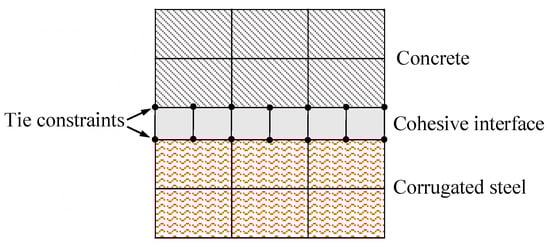
Figure 18.
The interaction behaviour between CSP and concrete.
The boundary and loading conditions of FE models were defined to replicate the supports and loads employed in the experimental tests. For the column specimens under axial compression, the bottom end of each specimen was fully fixed (U1 = U2 = U3 = UR1 = UR2 = UR3 = 0), while a vertical displacement loading was prescribed at the top of the specimen with the other five degrees of freedom being restrained. The developed FE model for the column specimens is shown in Figure 19, where the configuration details of CSP and rebars are also presented.
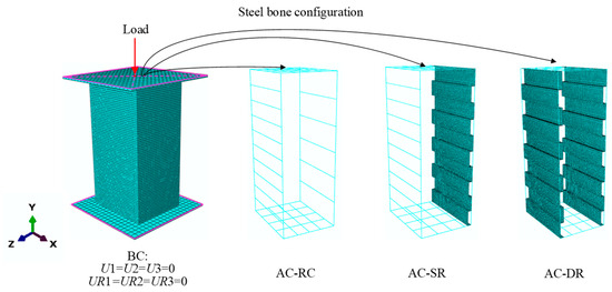
Figure 19.
FE model of column specimens.
For the beam specimens subjected to four-point bending, four bearing strips, which are assumed to be rigid solid elements, were established to mimic the load distribution. The two upper bearing strips were coupled to reference point RP1, and a vertical displacement was applied at RP1 to simulate displacement control loading. The displacements along with the x, y, and z axes and the rotations around the y and z axes of the fixed hinge support (RP2) were restrained (U1 = U2 = U3 = UR2 = UR3 = 0). Meanwhile, the displacements in the x and y axes and the rotations around the y and z axes of the roller support (RP3) were restrained (U1 = U2 = UR2 = UR3 = 0). The developed FE model of beam specimens is shown in Figure 20, and the details of load-carrying skeletons involving CSP and rebars are also provided. A static analysis with NLGEOM = YES was carried out for each column and beam specimen, accounting for the effect of geometric nonlinearity.
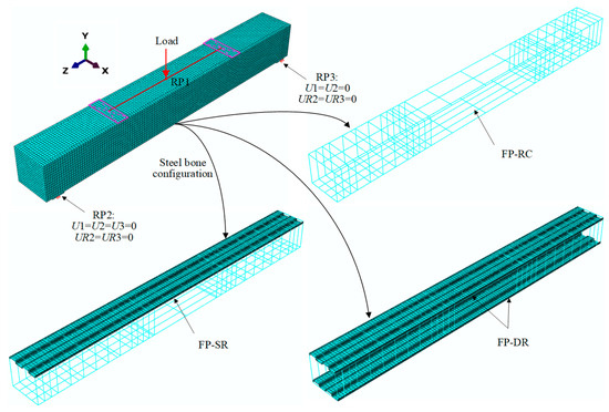
Figure 20.
FE model of beam specimens.
4.2. Validation of FE Models
The numerical simulation results of the axial compression tests and four-point bending tests were obtained and were compared with the previous experimental results in terms of the failure mode, the load versus deformation curves, and the load-carrying capacities. The predicted development of concrete cracks and stress distributions of CSP is shown in Figure 21a,b, respectively. For axial compression specimens, taking specimen AC-DR as an example, there were obvious X-shaped cross cracks in the concrete when the specimen was destroyed, as shown in Figure 21a, which was basically consistent with the test result. The grey area in the middle of the CSP represents the yield region of the material, as shown in Figure 21b. A large yield region occurred in the middle of the CSP under ultimate axial compression, and the stress decreased uniformly from the middle to both sides, which were consistent with the strain data of the test point.
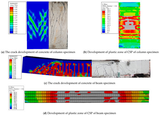
Figure 21.
Comparison of failure mode of specimens between FE and test results.
For bending specimens, taking specimen FP-SR1 as an example, the failure mode being shown in Figure 21c, there were only vertical cracks that appeared on the concrete surface, indicating no slip between the CSP and concrete. A large yield region occurred in the middle of the CSP under the ultimate bending moment, as shown in Figure 21d, and the stress decreases uniformly from the middle to both sides, which were consistent with the strain data of the test point, indicating that the finite element model can accurately simulate the test failure mode.
The FE modelling results of the load–deformation curves of the axial compression specimens are compared with the test results. As indicated in Figure 22a, it can be observed that the numerically predicted curves are in close agreement with the test curves. It is worth mentioning that the initial stiffness of the FE model is greater than the test stiffness due to the concrete in ABAQUS, which was defined as a uniform and isotropic material. In addition, the ultimate load-carrying capacity and ultimate deformation values of all axial compression specimens are compared with the experimental values. As shown in Table 5, the average values of Nu, FE/Nu, TEST ratios are calculated to be 1.01, with a small standard deviation of 0.06, and the mean ratio of Δu, FE/Δu, TEST is equal to 1.01, with a slightly higher standard deviation of 0.15, which may be attributed to possible assembly inaccuracy of the test set-up.
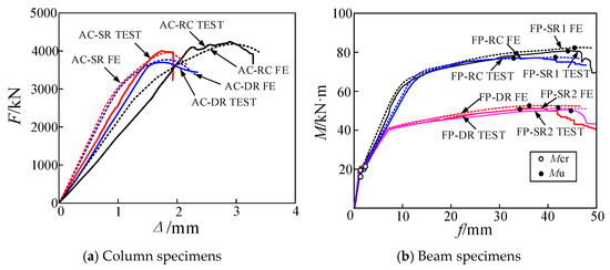
Figure 22.
Comparison of load–deformation curves of specimens between FE and test results.
And the bending moment–deflection curves are also compared with the test results. As indicated in Figure 22b and Table 6, the average values of Mcr, FE/Mcr, TEST and Mu, FE/Mu, TEST ratios are calculated to be 1.06 and 1.04, with small standard deviations of 0.03 and 0.03, respectively, and the mean ratio of fFE/fTEST is equal to 1.05, with a slightly higher standard deviation of 0.08. Based on the close agreement between FE modelling and testing, the developed FE models are deemed able to accurately capture the behaviour of rectangular corrugated steel-reinforced concrete specimen in axial compression and bending and have therefore verified the accuracy of the FE model.
“Given the high fidelity of the FE model, it can be extended to conduct systematic parametric analyses on the ‘accordion effect.’ Such research is crucial for understanding the interplay between corrugation profiles and axial performance. By exploring the influence of various half-wavelengths and depths, the model can guide the selection of optimal corrugation parameters, ensuring that the enhanced electromagnetic shielding does not come at the cost of compromised structural bearing capacity.”
It should be noted that the specimens in this study were reduced-scale components due to the constraints of the laboratory loading capacity. While the size effect might lead to variations in strength and ductility for larger structures, the high degree of consistency between the FEA and experimental results demonstrates the reliability of the numerical framework. This validated FE model can thus serve as a robust tool for future research to predict the mechanical performance of full-scale pipes and mitigate the potential impact of scaling effects.
5. Evaluation of Load-Carrying Capacity in Existing Standards
The existing standards, including the Chinese standard GB/T 11836 [38] and American standard ASTM C76 [48], provide design requirements and acceptance criteria for concrete pipe products. The three-edge bearing testing method was adopted in both standards. Specifically, the ultimate load requirement for reinforced concrete pipes in grade III with a wall thickness of 300 mm can be taken as 390 kN/m according to GB/T 11836, which results in a non-uniform bending moment in the pipe section [49], and the calculated ultimate bending moments at the crown and spring line of the pipe were equal to 62.78 kN·m and 33.75 kN·m, respectively. In ASTM C76, the ultimate load requirement for reinforced concrete pipes in grade IV is 426 kN/m, and the ultimate bending moments are 68.57 kN·m and 36.87 kN·m, corresponding to the crown and spring line of the pipe, respectively.
The previously obtained experimental and numerical ultimate bending moments values were compared to the required values in these two standards, and the results are summarised in Table 7. The comparison results were also plotted in Figure 23. It can be seen that the groups FP-RC and FP-SR1, which were designed in accordance with the cross-section at the crown of the pipe, satisfied the ultimate bending moment requirements, while the groups FP-SR2 and FP-DR exhibited lower capacities at the crown of the pipe, though both of them exceeded the capacity requirements at the spring line cross-section. It has been demonstrated that the introduction of a single layer of CSP is capable of providing an equivalent bending moment resistance compared to the conventional reinforced concrete counterparts, and the corrugated steel-reinforced concrete pipe can satisfy the requirements in existing Chinese and American standards.
Table 7.
Test, numerical, and calculated values of beam specimens.
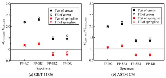
Figure 23.
Comparison of predictions from the specifications with available test and numerical results.
The comparison of the ultimate bending moments with GB/T 11836 and ASTM C76 provides clear application guidelines for CSRCPs. For the crown cross-section of reinforced concrete pipes with a 300 mm wall thickness (corresponding to Grade III in GB/T 11836 and Grade IV in ASTM C76), the single-layer CSP arrangement in the compression zone (FP-SR1) successfully meets the bending moment requirements of both specifications; furthermore, with a bending moment reserve of 13% to 28%, this configuration is confirmed for direct engineering application. Moving to the spring line cross-section, the double-layer CSP specimens (FP-DR) demonstrate a significantly higher ultimate capacity—exceeding specification requirements by 47% to 59%—which proves to be highly effective for enhancing the local bearing capacity under non-uniform soil pressure conditions. Consequently, when designing CSRCPs with varying wall thicknesses and diameters, the finite element (FE) model validated in this study can be utilised to calculate ultimate bearing capacity, allowing for direct comparison with the three-edge bearing test requirements of both standards to ensure comprehensive structural compliance.
6. Conclusions
A novel type of corrugated steel-reinforced concrete pipe constructed with the pipe jacking method was proposed. The axial compression and bending behaviour of corrugated steel-reinforced concrete cross-sections were separately studied by experimental testing and numerical simulation, from which the following conclusions can be drawn:
- The axial load capacity of rectangular corrugated steel-reinforced concrete cross-sections was close to that of the conventional reinforced concrete ones, though the failure mode of the axial compression specimens varied with the load-carrying skeletons. The ultimate bending moments of beam specimens with CSP were slightly higher than those of the reinforced concrete ones, and two different failure modes were obtained due to the yielding of CSP and steel rebars.
- Elaborate FE models of column specimens and beam specimens were separately developed. The damage-plastic constitutive model of concrete and the constitutive model of CSP were adopted, and the contact relationship between CSP and concrete was carefully prescribed. The developed FE models were validated against the obtained test results in the form of the load-carrying capacity and the failure modes. It was also revealed that the simulated strain distribution of CSP was in close agreement with the experimental results.
- The obtained test and FE results were compared with the design requirements and acceptance criteria outlined in the existing standards, including GB/T 11836 and ASTM C76, and it has been demonstrated that the introduction of a single layer of CSP in concrete pipes can meet the requirements in existing Chinese and American standards. In engineering design, single-layer CSP is recommended for the pipe’s jacking and crown compression zones, with high-strength steel rebars in the crown tensile zone.
While corrugated steel-reinforced concrete cross-sections often comply with existing standards, comprehensive testing of full-scale pipes and parametric studies is usually required to further validate their structural performances. These investigations will be the subject of future research, which will also extend to exploring structural responses under eccentric loading, non-uniform soil pressure, and other complex service conditions, to provide a more robust basis for its engineering application and structural design.
Author Contributions
Conceptualization, Y.F.; Methodology, X.D.; Formal analysis, Y.L.; Investigation, Z.X., H.Y. and Z.L.; Resources, Y.J.; Data curation, Y.L.; Writing—original draft, H.Y.; Writing—review & editing, Z.L.; Supervision, Y.J.; Project administration, Z.X.; Funding acquisition, Y.F. All authors have read and agreed to the published version of the manuscript.
Funding
This research received no external funding.
Data Availability Statement
The original contributions presented in the study are included in the article, further inquiries can be directed to the corresponding author.
Acknowledgments
The assistances from Changzheng Li and Fan Zhang for conducting the experimental work in this study are greatly appreciated.
Conflicts of Interest
Authors Yan Feng, Zongsheng Xu and Yufang Lin were employed by the company Wuhan Huayuan Electric Power Design Institute Co., Ltd. Author Yanyun Jin was employed by the company Wuhan Power Supply Company, State Grid Hubei Electric Power Co., Ltd. Author Xinxi Du was employed by the company Wuhan Gouzhu Construction Technology Co., Ltd. The remaining authors declare that the research was conducted in the absence of any commercial or financial relationships that could be construed as a potential conflict of interest.
References
- Du, X.X.; Li, C.Z.; Yuan, H.X.; Zhang, F.; Gan, S.X. Research on flexural performances of sinusoidal corrugated steel-reinforced concrete beams. Ind. Constr. 2022, 3, 158–163. (In Chinese) [Google Scholar]
- Fei, W.; Dai, W.; Mao, Y.H.; Zhao, D.D.; Cao, H.J.; Liu, J.H. Study on electromagnetic loss and shielding performance of concrete in protective engineering. Concrete 2022, 12, 185–188. [Google Scholar]
- Xu, L.; Li, X.; Li, Z.W.; Li, C.Z.; Zhong, T. Flexural behavior of novel CFDST components with external welded corrugated steel tubes. Structures 2023, 52, 42–56. [Google Scholar] [CrossRef]
- Fang, Y.; Wang, Y.Y.; Yang, T.Y.; Yang, H. Seismic behaviour and modelling of reinforced concrete-filled galvanized corrugated steel tubes. J. Constr. Steel Res. 2023, 202, 107785. [Google Scholar] [CrossRef]
- Li, Y.; Fu, X.S.; Li, B.J. Experimental study on mechanical properties of reinforced concrete pipe culverts slip lined with different steel liners. Highw. Eng. 2020, 2, 116–122. [Google Scholar]
- Gan, S.X.; Zhang, F.; Du, X.X.; Yuan, H.X.; Li, C.Z.; Jiang, Q.Z. A Rectangular Corrugated Steel Reinforced Concrete Pipe Jacking. Chinese Patent CN215956007U, 4 March 2022. Available online: http://epub.cnipa.gov.cn/patent/CN215956007U (accessed on 3 March 2026). (In Chinese)
- Yuan, H.X.; Jiang, Q.Z.; Du, X.X.; Zhang, F.; Li, C.Z. Simulation analysis on section cracks of reinforced concrete pipe used for jacking construction. China Concr. Cem. Prod. 2022, 11, 35–38. (In Chinese) [Google Scholar]
- Papangelis, J.; Trahair, N.; Hancock, G. Direct strength method for shear capacity of beams with corrugated webs. J. Constr. Steel Res. 2017, 137, 152–160. [Google Scholar] [CrossRef]
- Lee, H.D.; Lee, S.H.; Shin, K.J.; Lee, J.S. Shear strength evaluation of steel beams with partially corrugated web. J. Constr. Steel Res. 2023, 211, 108179. [Google Scholar] [CrossRef]
- Nie, J.G.; Zhu, Y.J.; Tao, M.X.; Guo, C.R.; Li, Y.X. Optimized prestressed continuous composite girder bridges with corrugated steel webs. ASCE J. Bridge Eng. 2017, 22, 04016121. [Google Scholar] [CrossRef]
- Liu, Q.C.; Han, G.J.; Bian, Z.J. Static Experimental Study on 42m Span Three-Dimensional Corrugated Steel Plate Arch Structure. In Proceedings of the National Modern Structural Engineering Academic Meeting, Tianjin, China, 2008; pp. 1173–1181. (In Chinese) [Google Scholar]
- Flener, E.B. Response of long-span box type soil-steel composite structures during ultimate loading tests. J. Bridge Eng. 2009, 14, 496–506. [Google Scholar] [CrossRef]
- Morrison, T.D. Innovative low cover bridges utilizing deepcorrugated steel plate with encased concrete composite ribs. In Proceedings of the 2005 Annual Conference of the Transportation Association of Canada, Calgary, AB, Canada, 18–21 September 2025. [Google Scholar]
- Flores-Johnson, E.A.; Li, Q.M. Structural behaviour of composite sandwich panels with plain and fibre-reinforced foamed concrete cores and corrugated steel faces. Compos. Struct. 2017, 94, 1555–1563. [Google Scholar] [CrossRef]
- Berman, J.; Bruneau, M. Experimental investigation of light-gauge steel plate shear walls. J. Struct. Eng. ASCE 2005, 131, 259–267. [Google Scholar] [CrossRef]
- Li, W.; Chen, H.; Li, F. Performance of concrete-filled double-skin shallow-corrugated steel plate composite walls under compression-bending load. J. Constr. Steel Res. 2023, 201, 107701. [Google Scholar] [CrossRef]
- Chen, Z.; Liu, X. Experimental Study on Seismic Performance of Transversely Ribbed Corrugated Steel Plate–Steel Pipe Concrete Shear Wall. Buildings 2024, 14, 2708. [Google Scholar] [CrossRef]
- Ghodratian-Kashan, S.M.; Maleki, S. Experimental investigation of double corrugated steel plate shear walls. J. Constr. Steel Res. 2022, 190, 107138. [Google Scholar] [CrossRef]
- Emami, F.; Mofid, M. On the hysteresis behavior of trapezoidally corrugated steel shear walls. Struct. Des. Tall Spec. Build. 2014, 23, 94–104. [Google Scholar] [CrossRef]
- Wang, S.H.; Liu, Y.Q.; He, J.; Xin, H.H.; Yao, H.B. Experimental study on cyclic behaviour of composite beam with corrugated steel web considering different shear-span ratio. Eng. Struct. 2019, 180, 669–684. [Google Scholar] [CrossRef]
- Elamary, A.; Ahmed, M.M.; Mohmoud, A.M. Flexural behaviour and capacity of reinforced concrete-steel composite beams with corrugated web and top steel flange. Eng. Struct. 2017, 135, 136–148. [Google Scholar] [CrossRef]
- Wu, F.W.; Fan, Z.; He, L.Q.; Liu, S.; Zuo, J.; Yang, F. Comparative study of the negative bending behaviour of corrugated web steel-concrete composite beams using NC, ECC and UHPC. Eng. Struct. 2023, 283, 115925. [Google Scholar] [CrossRef]
- He, J.; Wang, S.; Liu, Y.; Li, C. Mechanical behavior of a partially encased composite girder with corrugated steel web: Interaction of shear and bending. Engineering 2017, 3, 806–816. [Google Scholar] [CrossRef]
- Wang, X.; Miao, C.; Wang, X. Prediction analysis of deflection in the construction of composite box-girder bridge with corrugated steel webs based on MEC-BP neural networks. Structures 2021, 32, 691–700. [Google Scholar] [CrossRef]
- Wang, Y.Y.; Yang, L.G.; Yang, H.; Liu, C.Y. Behaviour of concrete-filled corrugated steel tubes under axial compression. Eng. Struct. 2019, 183, 475–495. [Google Scholar] [CrossRef]
- Yuan, H.X.; Du, X.X.; Shokouhian, M.; Ye, J.; Schafer, B.W. Behaviour and design of circular hollow section steel columns strengthened by infilling concrete under preload. J. Constr. Steel Res. 2019, 159, 415–427. [Google Scholar] [CrossRef]
- Hee, T.H.; Won, D.; Kim, S.; Kang, Y.J. Experimental study on the lateral behavior of DSCT columns with corrugated inner tube. Mater. Struct. 2015, 48, 2855–2867. [Google Scholar]
- Kim, C.S.; Lee, H.J.; Park, C.K.; Hwang, H.J.; Park, H.G. Cyclic loading test for concrete-filled hollow precast concrete columns produced by using a new fabrication method. J. Struct. Eng. 2017, 143, 04016212. [Google Scholar] [CrossRef]
- Sun, H.; Zhang, L.; Liu, Y.; Liu, B.; Feng, M. Axial compression behavior of large-diameter, concrete-filled, thin-walled galvanized helical corrugated steel tubes column embedded with rebar. Buildings 2023, 14, 24. [Google Scholar] [CrossRef]
- John, K.; Ashraf, M.; Weiss, M.; Al-Ameri, R. Experimental Investigation of Novel Corrugated Steel Deck under Construction Load for Composite Slim-Flooring. Buildings 2020, 10, 208. [Google Scholar] [CrossRef]
- Chou, C.C.; Lee, C.S.; Wu, K.Y.; Chin, V.L. Development and validation of a frp-wrapped spiral corrugated tube for seismic performance of circular concrete columns. Constr. Build. Mater. 2018, 170, 498–511. [Google Scholar] [CrossRef]
- Sun, Z.X.; Zou, Y.; Wang, C.Q.; Pan, J.; Wang, L.; Chen, M. Axial compressive behavior and load-bearing capacity of steel tubular-corrugated steel plate confined concrete composite columns. Structures 2022, 44, 135–151. [Google Scholar] [CrossRef]
- Ni, C.Y.; Hou, R.; Xia, H.Y.; Zhang, Q.C.; Wang, W.B.; Cheng, Z.H.; Lu, T.J. Perforation resistance of corrugated metallic sandwich plates filled with reactive powder concrete: Experiment and simulation. Compos. Struct. 2015, 127, 426–435. [Google Scholar] [CrossRef]
- Liu, B.D.; Zhang, Z.N.; Zhang, M.Q.; Wang, X.X. Experimental study of the mechanical performance of corrugated steel plate-concrete composite structures. Int. J. Steel Struct. 2019, 19, 733–746. [Google Scholar] [CrossRef]
- Lacki, P.; Nawrot, J.; Derlatka, A.; Winowiecka, J. Numerical and experimental tests of steel-concrete composite beam with the connector made of top-hat profile. Compos. Struct. 2019, 211, 244–253. [Google Scholar] [CrossRef]
- Song, J.L.; Wang, W.; Su, S.Q.; Ding, X.B.; Luo, Q.R.; Quan, C.C. Experimental study on the bond-slip performance between concrete and a corrugated steel plate with studs. Eng. Struct. 2020, 224, 111195. [Google Scholar] [CrossRef]
- Xia, Q.L.; Wang, Y.Y.; Jelovica, J.; Liu, C.Y.; Sun, D.W. Experimental study on corrugated steel-concrete composite semicircular arches under midspan loading. Structures 2022, 38, 1137–1150. [Google Scholar] [CrossRef]
- GB/T 11836; Concrete and Reinforced Concrete Sewer Pipes. China Architecture & Building Press: Beijing, China, 2023. (In Chinese)
- GB 50017; Standard for Design of Steel Structures. China Architecture & Building Press: Beijing, China, 2018. (In Chinese)
- GB/T 50081; Standard for Test Methods of Concrete Physical and Mechanical Properties. China Architecture & Building Press: Beijing, China, 2019. (In Chinese)
- GB/T 50152; Standard for Test Method of Concrete Structures. China Architecture & Building Press: Beijing, China, 2012. (In Chinese)
- Tao, M.X.; Nie, J.G. Multi-scale modeling for deformation mechanism analysis of composite joint substructures. Eng. Struct. 2016, 118, 55–73. [Google Scholar] [CrossRef]
- Tao, M.X.; Nie, J.G. Fiber beam-column model considering slab spatial composite effect for nonlinear analysis of composite frame systems. J. Struct. Eng. ASCE 2014, 140, 04013039. [Google Scholar] [CrossRef]
- Zhang, J.; Wang, Q.Y.; Hu, S.Y. Parameters verification of concrete damaged plastic model of ABAQUS. Build. Struct. 2008, 8, 127–130. (In Chinese) [Google Scholar]
- GB50010; Code for Design of Concrete Structures. China Architecture & Building Press: Beijing, China, 2010. (In Chinese)
- Du, X.X.; Hu, R.; Yuan, H.X.; Cheng, X.Y.; Zong, L. Experimental study on shear behavior of prestressed concrete pipe pile with hybrid reinforcement. Eng. Mech. 2018, 35, 71–80. (In Chinese) [Google Scholar]
- Wang, W.; Li, Y.; Su, S.Q.; Quan, C.C.; Mi, J.X.; Xu, J.; Jia, Y. Interfacial bonding stress transfer and failure mechanism between corrugated steel plate and reinforced concrete. Eng. Fail. Anal. 2023, 153, 107555. [Google Scholar] [CrossRef]
- ASTM C76; Specification for Reinforced Concrete Culvert, Storm Drain, and Sewer Pipe. ASTM International: West Conshohocken, PA, USA, 2016.
- Zhu, Z.H.; Zhang, P.; Ma, B.S.; Zeng, C.; Zhao, Y.H.; Wang, F.Z.; Li, Z.H.; Xiang, W.G.; Ariaratnam, S.T.; Yan, X.F. Quantitative model for residual bearing capacity of corroded reinforced concrete pipe based on failure mode. Tunn. Undergr. Sp. Technol. 2022, 129, 104675. [Google Scholar] [CrossRef]


Disclaimer/Publisher’s Note: The statements, opinions and data contained in all publications are solely those of the individual author(s) and contributor(s) and not of MDPI and/or the editor(s). MDPI and/or the editor(s) disclaim responsibility for any injury to people or property resulting from any ideas, methods, instructions or products referred to in the content. |
© 2026 by the authors. Licensee MDPI, Basel, Switzerland. This article is an open access article distributed under the terms and conditions of the Creative Commons Attribution (CC BY) license.