


Abstract
Improving the seismic performance and post-earthquake reparability of steel moment connections requires designs that concentrate inelastic deformation in replaceable components while protecting primary structural members. Column-tree connections, which combine shop-welded beam stubs with field-bolted beam spans, offer a potential solution. However, experimental evidence remains limited for configurations incorporating conventional rectangular fuse plates. This study investigates their cyclic performance through eight full-scale tests conducted according to the AISC seismic loading protocol, complemented by calibrated finite element simulations. The experimental variables included the number of flange bolts, cover plate thickness, and beam stub length. All specimens sustained a drift ratio of 4% and exceeded 80% of the nominal beam plastic moment capacity. The experimental results revealed that the influence of bolt quantity on connection strength and energy dissipation depends on cover plate thickness, while beam stub length also affects the cyclic response. Inelastic deformation was predominantly concentrated in the replaceable cover plates, with no visible fracture or local buckling observed in the primary structural members. Energy dissipation involved frictional sliding during the initial response and localized cover plate yielding at larger drift demands, although the individual contributions of these mechanisms were not quantified separately. The numerical models reproduced the principal deformation mechanisms and overall hysteretic behavior, although discrepancies remained in stiffness and peak strength. The findings provide experimental evidence supporting the feasibility of damage-controlled column-tree moment connections incorporating conventional replaceable cover plates, while highlighting the influence of connection detailing on cyclic performance and post-earthquake reparability.
1. Introduction
The seismic performance of steel moment-resisting frames (MRFs) has been widely recognized as satisfactory; however, their global strength, ductility, and energy dissipation capacity are strongly governed by the characteristics of the beam-to-column connections. Steel moment connections may be classified as rigid or semi-rigid, with fully restrained connections being predominantly adopted in seismic-resistant steel structures [1]. This design philosophy aims to ensure that inelastic demand is primarily accommodated through flexural yielding of the beams while maintaining elastic behavior in the columns, thereby promoting stable global mechanisms and preventing story collapse.
Within this framework, column-tree moment connections were introduced in the late twentieth century as an alternative construction strategy to improve fabrication efficiency and quality control. The concept involves welding short beam segments, commonly referred to as stubs or branches, to the column flanges in the fabrication shop, followed by bolting the remaining beam spans on site. This hybrid assembly significantly reduces field welding operations, which are known to be sensitive to workmanship and environmental conditions, and consequently improves construction safety and reliability [2].
Early experimental investigations by [3] demonstrated that column-tree frames with reduced splice plates (this solution requires further work and leads to a reduction in lateral stiffness of the structural system) could develop stable cyclic behavior, although inelastic deformation was mainly concentrated in the splice plates through yielding and bolt slippage. Subsequent studies further explored alternative design strategies to enhance ductility and delay brittle failure. On the other hand, ref. [4] proposed ductile connection details without weld access holes and with widened stub flanges, achieving stable hysteretic behavior but with damage localized in the stub beam. Similar conclusions were reported by [5], who showed that column-tree configurations could reach drift ratios up to 5%, although with plastic deformation concentrated in the beam.
Other researchers attempted to improve cyclic performance by modifying the geometry of the stub beam. Refs. [6,7] demonstrated that varying the stub length or widening its cross section, combined with additional stiffening, could increase ductility and reduce damage accumulation, although the stub beam remained the primary location of inelastic deformation. The use of tapered or widened beam flanges was further investigated by [8], who observed the formation of plastic hinges in the stub beam, confirming that damage localization in primary members persists even in enhanced configurations.
Several studies have focused on intentionally weakening the beam splice to shift plastic demand away from the beam. Ref. [9] tested column-tree connections with bearing-type and reduced beam splices and reported that although weakened splices improved energy dissipation, fracture of the stub beam and local buckling of the connection region still occurred. Additionally, parametric studies on splice length [10] and weak-axis configurations with reduced beam sections [11,12] similarly achieved ductile responses up to 5% story drift, yet fracture and local instability of the stub or beam flanges were frequently observed. The influence of composite action with slabs was examined by [12], who reported severe slab crushing and cracking near the joint region, further highlighting the vulnerability of conventional column-tree configurations.
Complementary numerical investigations have addressed stress redistribution mechanisms and the influence of bolted splices located in plastic hinge regions [13,14], demonstrating that bolt slippage and stress concentration around bolt holes may reduce energy dissipation capacity and promote crack initiation. Experimental and numerical studies on alternative configurations, including Z-type cantilever beam splices [15] and the effects of bolt-hole clearance and pretension [16], confirmed that although acceptable global performance can be achieved, local damage in the stub beam remains difficult to avoid.
More recently, ref. [17] highlighted that the prequalification of column-tree connections strongly depends on parameters such as stub length and splice location; however, their conclusions were derived solely from numerical simulations, without experimental verification. Parallel research efforts have investigated supplemental energy dissipation devices, including slit dampers [18], modified cover plates [19], and replaceable structural fuses [19,20,21]. Recent studies have also explored replaceable plastic hinges in precast reinforced concrete frames [22] and buckling-restrained braces for seismic retrofitting [23]. For steel structures, Di Benedetto et al. [24] experimentally investigated a two-story building equipped with low-damage friction joints. These studies demonstrate different strategies for limiting seismic damage through localized energy dissipation and replaceable or repairable components. Nevertheless, experimental evidence remains limited for column-tree moment connections incorporating conventional rectangular replaceable cover plates, which constitute the focus of the present study.
On the other hand, Valente et al. [25,26] investigated replaceable steel-plate fuses in composite steel moment-resisting frames through experimental testing and numerical analyses, demonstrating their effectiveness in concentrating inelastic deformation within sacrificial components. Unlike these configurations, the present study focuses on column-tree moment connections incorporating conventional rectangular cover plates in bolted beam splices. Particular emphasis is placed on experimentally evaluating the combined effects of beam stub length, flange bolt quantity, and cover plate thickness on cyclic behavior, frictional energy dissipation, and damage localization.
Overall, existing studies indicate that the cyclic behavior of column-tree moment connections remains insufficiently characterized, particularly regarding the control and localization of inelastic deformation. Two main design philosophies have been pursued: (i) promoting plastic hinge formation in beams or stubs while maintaining elastic behavior in columns, and (ii) concentrating inelastic deformation in replaceable connection components to protect primary structural members. Nevertheless, experimental evidence indicates that fracture, local buckling, or severe yielding of the stub beam and adjacent beam segments frequently occur, even in advanced or weakened-splice configurations. Consequently, there remains a need for experimentally validated connection details capable of concentrating damage in sacrificial components while preserving the integrity of beams and columns using simple, conventional fabrication components.
To address this gap, the authors previously conducted a numerical study [27] based on the second design philosophy, in which inelastic demand was intentionally concentrated in replaceable cover plates. That study demonstrated the numerical feasibility of preventing damage to stub beams and columns and proposed a corresponding design methodology. However, the lack of experimental validation limits the applicability of these findings to seismic design practice and connection prequalification. In particular, experimental investigation is needed to establish whether the proposed damage-control mechanism can be achieved under cyclic loading and to assess the influence of key connection parameters on the resulting structural response.
The objective of the present study is to experimentally evaluate the seismic performance of column-tree moment connections incorporating replaceable rectangular cover plates designed to act as structural fuses, in accordance with the requirements of AISC 341 and AISC 358 [28,29]. A full-scale cyclic testing program is conducted to assess whether inelastic deformation can be effectively confined to the replaceable cover plates while preventing fracture or instability in the beam stubs, beam spans, and columns. The study also examines the influence of three key design parameters: stub beam length, number of flange bolts, and cover plate thickness on hysteretic behavior, strength degradation, and energy dissipation. The main contribution of this research is the experimental assessment of the damage-control concept previously investigated using numerical study, providing evidence of the conditions under which replaceable rectangular cover plates can accommodate inelastic demands while protecting primary structural members. The novelty lies in experimentally investigating this fuse-based mechanism in column-tree moment connections assembled using conventional fabrication components, together with a systematic evaluation of the influence of the selected design parameters on cyclic performance. By linking the previously proposed numerical design approach with full-scale experimental observations, the study provides a basis for assessing the feasibility of a practical, cost-effective, and repairable connection solution aimed at improving the post-earthquake resilience of steel moment-resisting frames.
2. Experimental Program
2.1. Description of Specimens
In this study, the joint configurations were derived from a steel building previously designed for seismic loading, consisting of three bays and three stories and located in Santiago, Chile. The building employs steel moment-resisting frames. The cross-sectional dimensions of beams and columns were determined through an iterative trial-and-error design process. Compliance with the strong column–weak beam criterion and elastic behavior of the panel zone in shear was ensured in accordance with the procedures specified in [28,29].
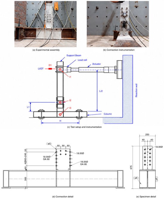
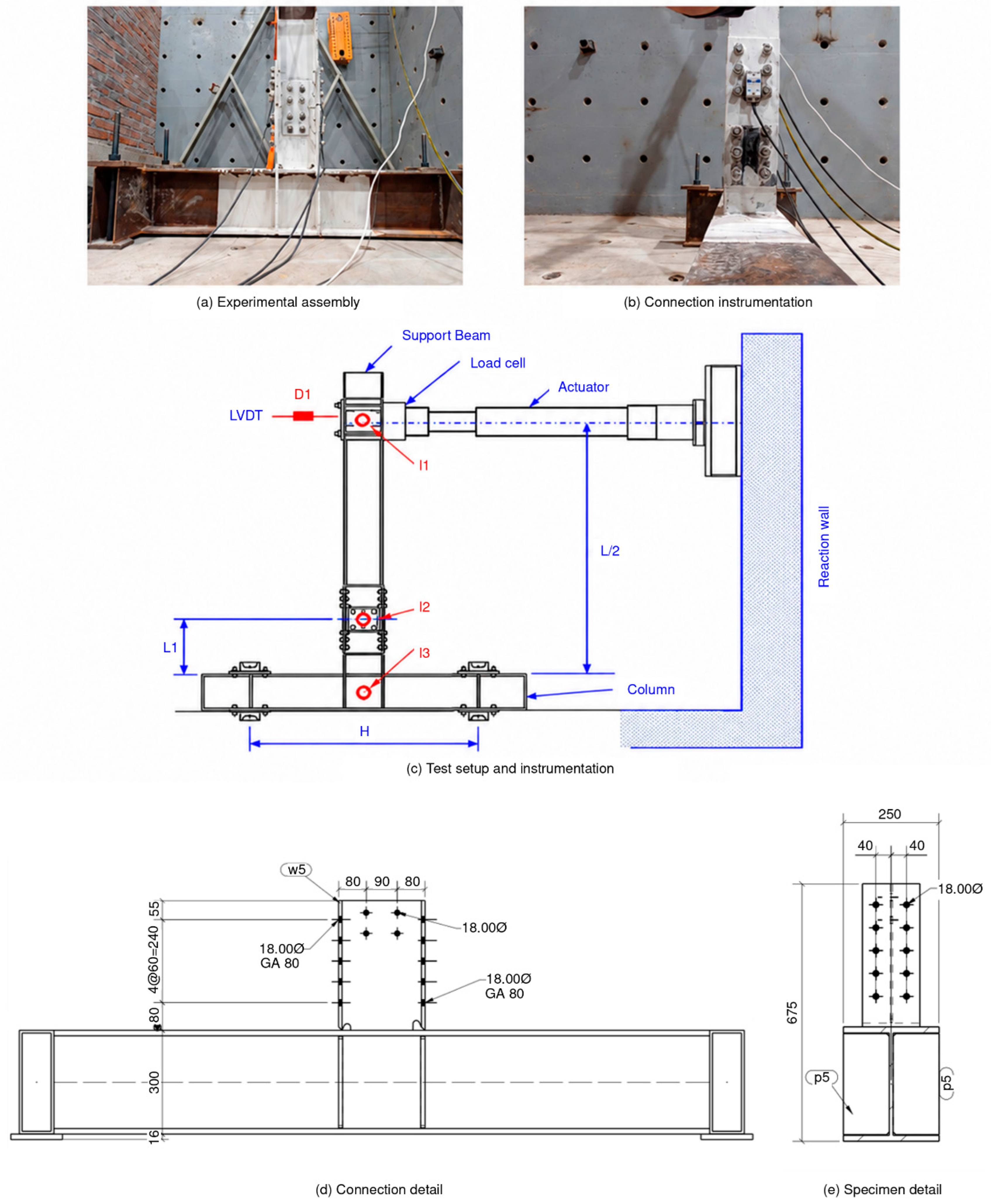
A schematic representation of the experimental setup and its main dimensions are shown in Figure 1. Bolt spacing and edge distances were selected based on standard detailing practices. The geometric properties of all structural components are summarized in Table 1. The beams and columns were fabricated as welded built-up sections using ASTM A36 steel plates [30]. The anchorage beams were constructed as box sections assembled from ASTM A36 channels. Complete joint penetration (CJP) welds were used to connect the beam stubs to the column flanges, while fillet welds were adopted for the stiffeners.
Figure 1.
Experimental setup. All geometrical dimensions are shown in millimeters (mm).
Table 1.
Dimensions of structural sections.
To evaluate the cyclic behavior of the proposed moment connection configurations, a total of eight full-scale specimens were designed and tested under quasi-static cyclic loading. The experimental matrix was established based on the systematic combination of three key design variables, namely the stub beam length, the number of bolts in the flange splice, and the thickness of the cover plates.
These parameters were selected to investigate their individual and combined influence on strength, stiffness degradation, energy dissipation capacity, and failure mechanisms of the connections. Each specimen represents a distinct configuration within the experimental program, allowing for a comprehensive comparison of structural performance under increasing deformation demands. The detailed geometric and mechanical characteristics of the specimens, as well as the corresponding values of the governing parameters, are summarized in Table 2.
Table 2.
Summary of the specimens tested.
2.2. Material Properties
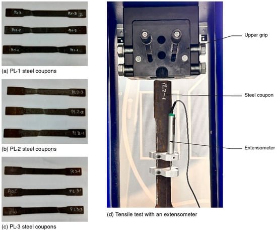
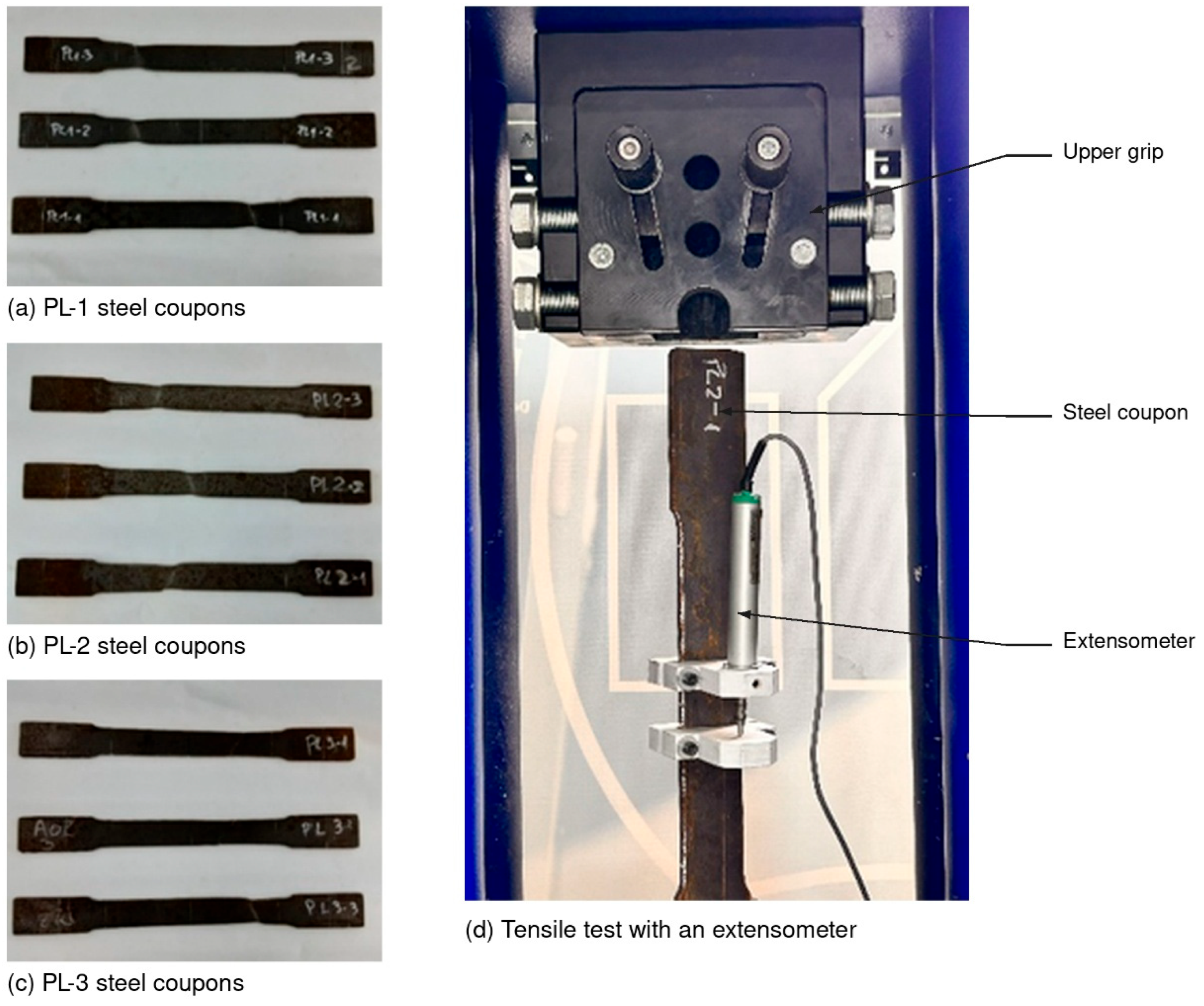
The welded beams are made from 6 mm and 10 mm plates, and connection material includes 8 mm and 10 mm plates. The material properties were obtained from coupon tensile tests (see Figure 2) of the same steel batch. A summary of the material properties is shown in Table 3.
Figure 2.
Coupon steel obtained from cover plates used in splices.
Table 3.
Material properties for coupon steel tested.
The welded beam members were fabricated using steel plates with nominal thicknesses of 6 mm and 10 mm, while the connection components, including cover plates and stiffeners, were manufactured from plates with thicknesses of 8 mm and 10 mm. All steel materials were sourced from the same production batch to minimize variability in mechanical properties. The material characterization was conducted through standard uniaxial tensile coupon tests, as shown in Figure 2, following the testing procedures for structural steels. These tests provided the yield strength, ultimate tensile strength, elastic modulus, and elongation capacity required for both experimental interpretation and numerical modeling. The average values obtained from the coupon tests are summarized in Table 3 and were subsequently adopted in the finite element simulations to ensure consistency between the experimental and numerical analyses.
2.3. Test Setup and Instrumentation
Eight full-scale specimens were tested under quasi-static cyclic loading in the Structural Engineering Laboratory of the Department of Civil Engineering at Universidad Católica de la Santísima Concepción (UCSC), Chile. The experimental setup was designed to reproduce the boundary conditions of an interior beam-to-column joint in a moment-resisting frame. Cyclic displacement-controlled loading was applied at the free end of the beam, while pinned boundary conditions were imposed at both ends of the column.
The load was applied using a 250 kN hydraulic actuator connected to a rigid reaction wall. The column base was supported on a concrete reaction slab, while the beam was subjected to cyclic loading through the actuator, as illustrated in Figure 1. The bending moment at the column centerline was calculated by multiplying the applied force, measured by the load cell installed at the actuator tip, by the corresponding lever arm, defined as the distance between the load application point and the column centerline. The system rotation was determined by dividing the beam-end displacement, recorded by an LVDT at the loading point, by the same lever arm, assuming small rotations. Additional LVDTs were used to independently verify the calculated rotations. This instrumentation arrangement enabled the experimental characterization of the moment–rotation response of the tested connections.
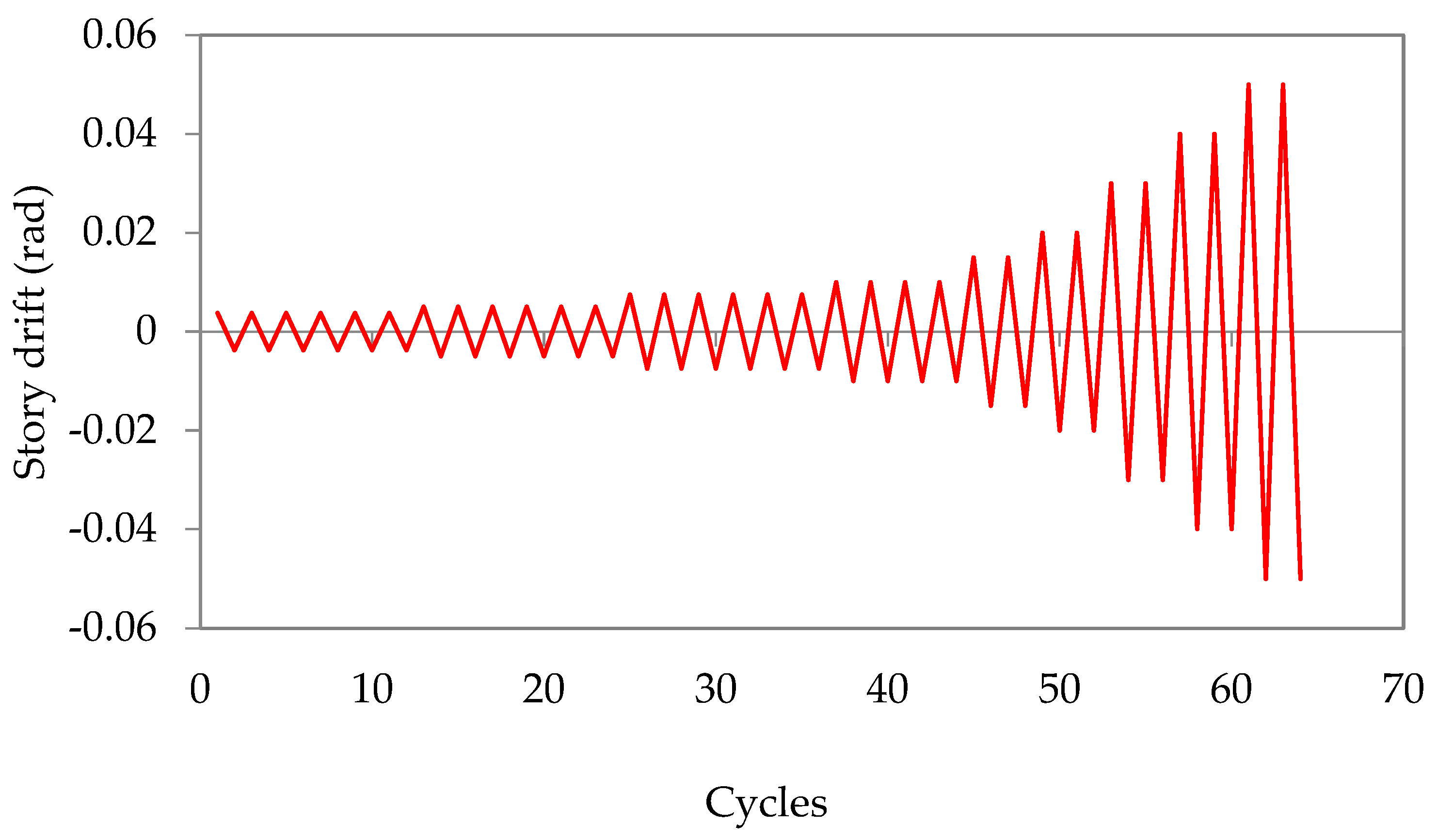
The drift ratio is defined as the lateral displacement imposed at the beam loading point divided by the corresponding reference length of the test assembly. This dimensionless quantity is expressed as a percentage throughout the experimental results. Thus, a drift ratio of 4% corresponds to a displacement-to-length ratio of 0.04, equivalent to an angular distortion of approximately 0.04 rad under the small-angle approximation. To ensure consistency, drift ratios are reported in percentage form, whereas local rotations measured by inclinometers are expressed in radians. Bolt pretension was applied using the calibrated wrench method in accordance with [29], with a target pretension force of 85 kN for each 5/8 in. diameter bolt. The cyclic loading protocol followed the requirements specified in [27], as illustrated in Figure 3. Although the prescribed loading history extends to a drift ratio of 0.06 rad, the quantitative comparisons reported in this study were limited to a drift ratio of 0.04 rad to provide a consistent basis for evaluating the eight specimens. Furthermore, the specimens were subjected to a drift amplitude of 5%; however, difficulties encountered during load application prevented the completion of a stable hysteresis cycle at this amplitude. Consequently, the reported strength and cumulative energy dissipation values should not be interpreted as representing the response at the maximum drift indicated in the loading protocol.
Figure 3.
Cyclic loading protocol applied during the experimental tests.
The assessment of cyclic performance in this study was conducted based on the following criteria:
Effect of cover plate thickness. Two cover plate thicknesses, 8 and 10 mm, were investigated to evaluate their influence on connection strength, cyclic deformation, and damage localization. The 8 mm plates were selected to provide a reduced-thickness connection detail, whereas the 10 mm plates matched the nominal thickness of the beam flanges. However, equal plate and flange thicknesses do not necessarily imply equal strength because the effective cross-sectional areas, bolt-hole reductions, stress distributions, and local bearing conditions differ. Accordingly, the experimental comparison was intended to evaluate the influence of plate thickness on the development and localization of inelastic deformation rather than to assume a predetermined strength hierarchy based solely on plate thickness.
Effect of bolt quantity. All connection bolts were pretensioned accoridng to ref. [31] and quality ASTM A325 [32]. The bolt diameter was limited to 16 mm (5/8 in.), and 17.5 mm diameter holes were drilled to prevent premature yielding or fracture in the net section of the beam flange. Based on the selected beam section, a minimum of six bolts per flange was required to provide sufficient shear capacity to resist the expected maximum bending moment at the connection. Given the clean, unpainted mill finish of the contact surfaces, a relatively low friction coefficient was anticipated at the faying surfaces. Consequently, an alternative configuration employing eight bolts per flange was also considered in the experimental program in order to investigate the influence of bolt quantity on the ultimate connection strength and on the level of energy dissipation associated with frictional sliding during cyclic loading.
Effect of beam stub length. As discussed by [27], in conventional moment-resisting frames the bending moment demand along the beam decreases approximately linearly with increasing distance from the column face. Based on this observation and considering a beam depth of d = 200 mm, two stub beam lengths were selected for the experimental program: L1 = 1.5d = 300 mm and L1 = 2.0d = 400 mm. Shorter stub lengths were considered impractical due to geometric constraints imposed by the dimensions of the connection plates and bolt arrangements, while longer lengths were expected to have a marginal influence on the global stiffness and cyclic response of the joint assembly. The selected values therefore provide a representative range to evaluate the influence of stub length on force transfer mechanisms, damage localization, and overall hysteretic behavior of the column-tree connections.
Required connection strength. Following the design concept proposed by [24], the bolted cover plates are intended to function as structural fuses, thereby preventing the development of plastic deformation at the welded joint between the beam stub and the column flange. Accordingly, the connection is designed such that yielding is preferentially concentrated in the cover plates, while the beam stub and column remain in the elastic range. The maximum expected bending moment at the column face is defined as Myb = Fyb × Sxb, where Fyb is the expected yield strength of the beam material and Sxb is the elastic section modulus of the beam. The maximum bending moment acting at the splice location is subsequently estimated as Mps = f × Myb, with the reduction factor , where L denotes the clear beam span and L1 the stub beam length. This formulation accounts for the linear variation in bending moment along the beam and provides a rational basis for defining the required strength of the cover plates to ensure controlled yielding and damage localization within the replaceable components.
3. Experimental Results
This section presents the results of the experimental program in terms of cyclic response, failure mechanisms, energy dissipation capacity, and stiffness degradation. For consistency, the quantitative comparisons of moment resistance and cumulative energy dissipation presented in this section are restricted to a drift ratio of 0.04 rad. The conclusions regarding cyclic performance are therefore limited to this deformation level. The structural behavior of the tested specimens is shown through normalized force–displacement hysteresis curves, following the same procedure adopted by [8,11]. A summary of the main response parameters is provided in Table 4. The dissipated energy was calculated as the enclosed area of each hysteretic loop per loading cycle. The maximum bending moment (Mmax) corresponds to the peak moment attained by each connection configuration during the tests, while the plastic moment capacity (Mp) was evaluated as Mp = FyZx, where Fy is the yield strength and Zx is the plastic section modulus of the beam, according to AISC 341 [29] (Mp = 250 × 333600 = 83.4 kN.m). Additionally, the initial stiffness and maximum moments at the column face and column centerline are reported for each specimen.
Table 4.
Summary of key parameters.
For all specimens, visible inelastic damage was predominantly concentrated in the replaceable connection plates, primarily through localized bearing deformation and yielding. No significant permanent deformation or local buckling was observed in the beam stubs, beams, or columns during post-test inspections.
3.1. Effect of Cover Plate Thickness
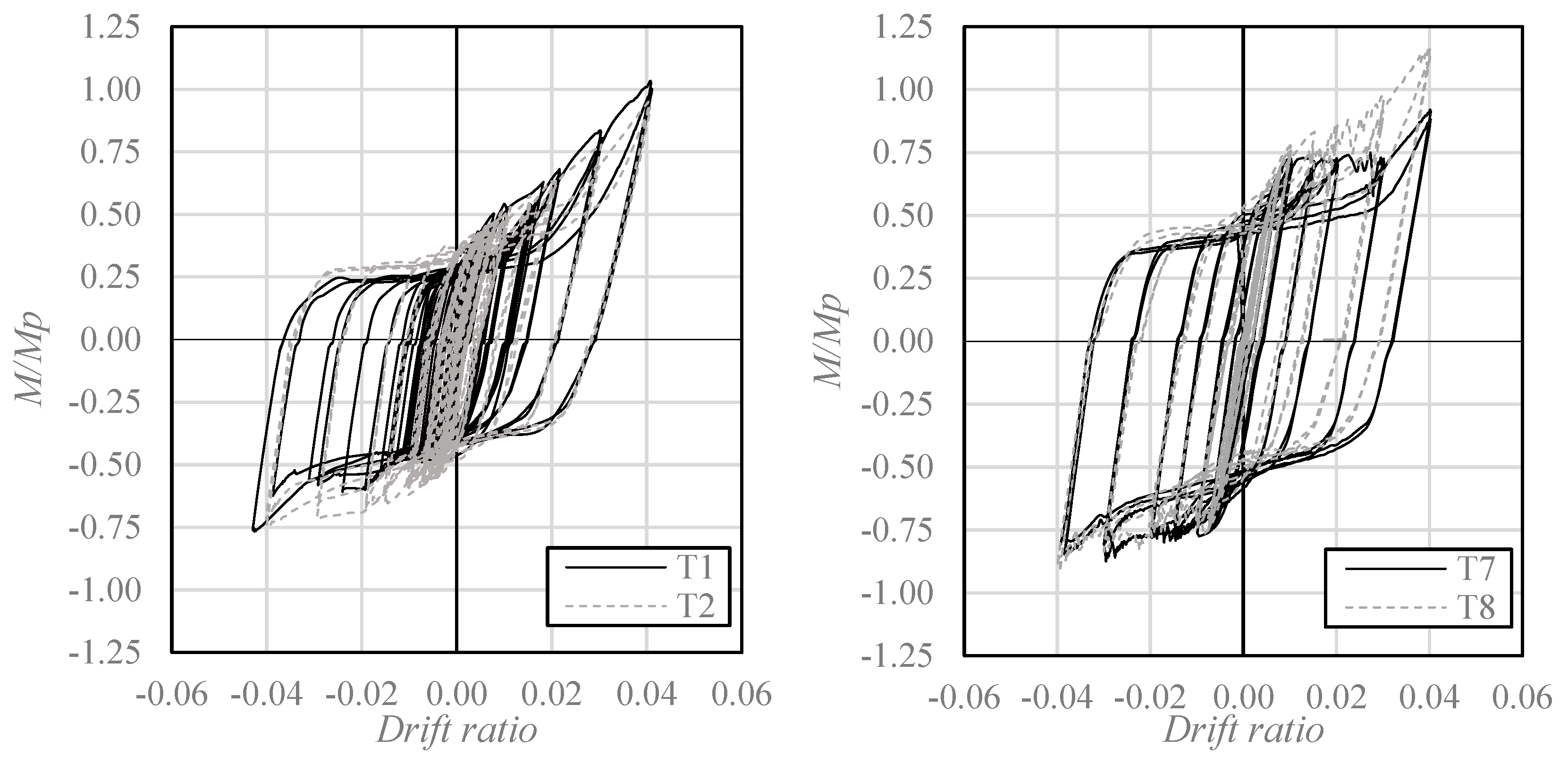
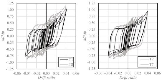
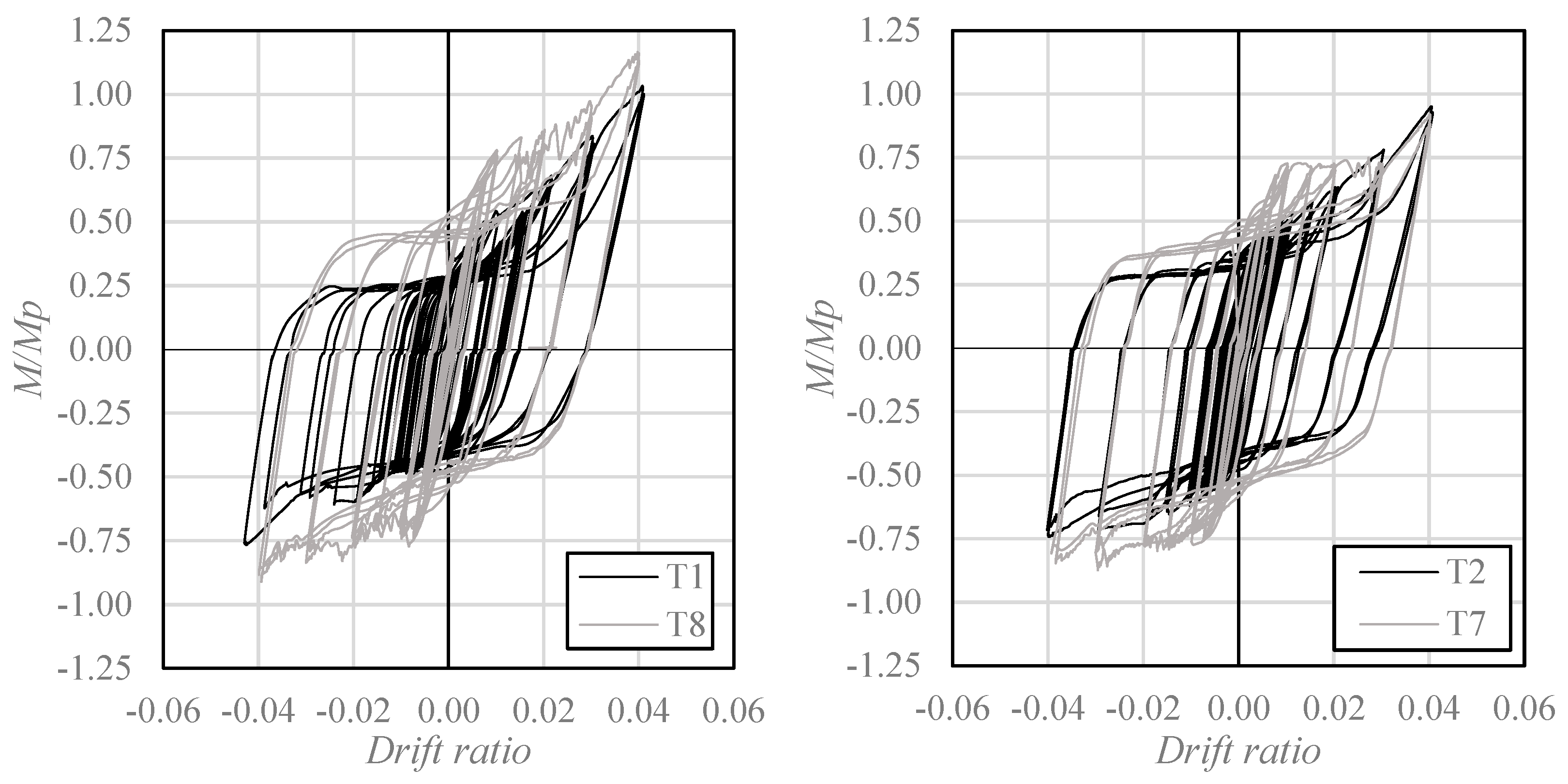
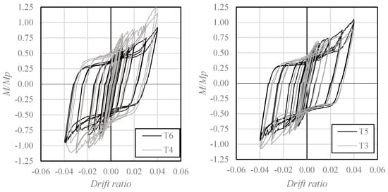
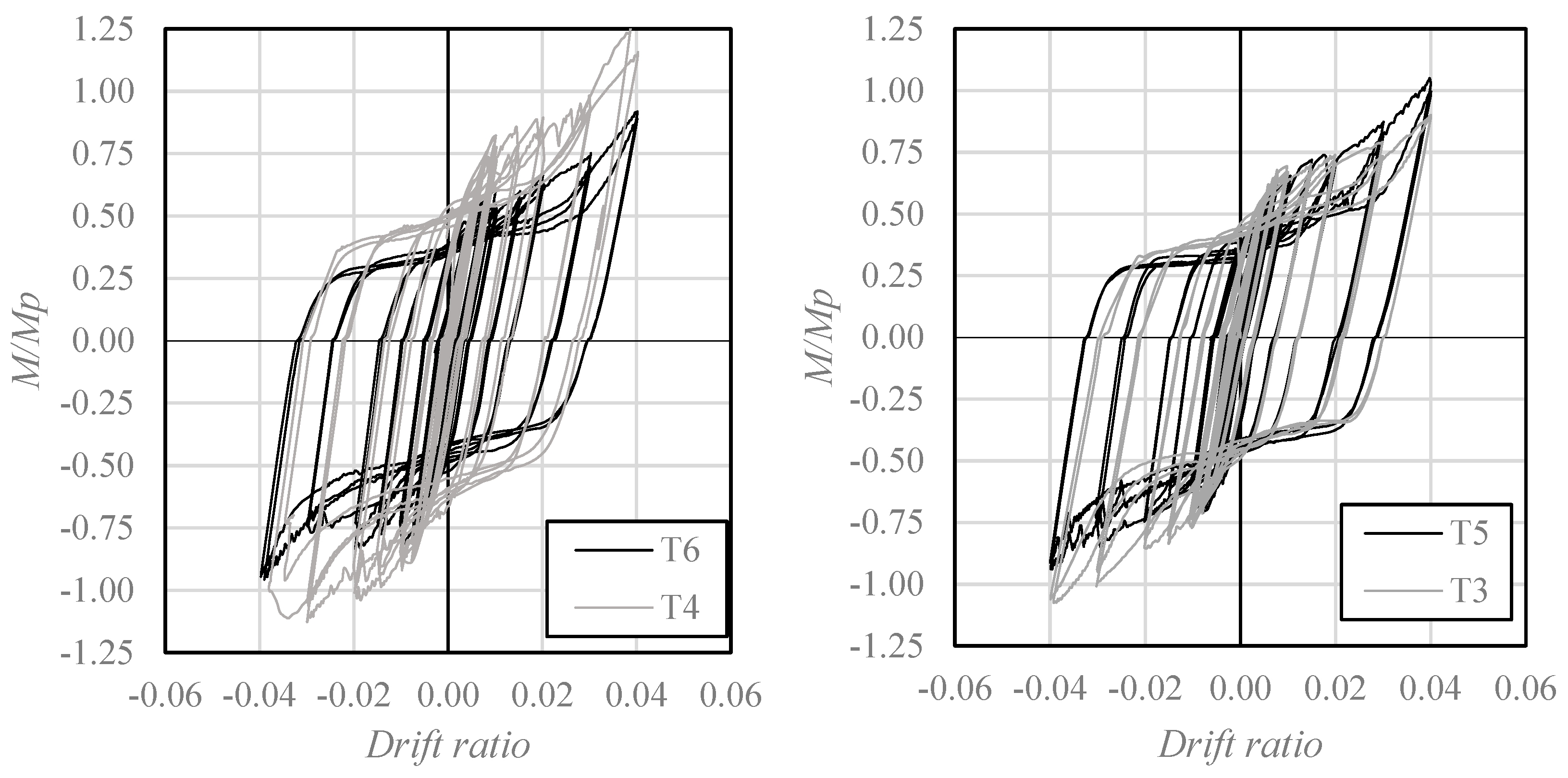
The influence of cover plate thickness on the cyclic response of the proposed connections is illustrated in Figure 4 and Figure 5. For specimens with a beam stub length of 300 mm (Figure 4), increasing the cover plate thickness from 8 to 10 mm increased the peak moment resistance by 8.6% for the six-bolt configuration (T2–T1) and by 26.7% for the eight-bolt configuration (T7–T8). These results indicate that the contribution of plate thickness to connection resistance depends on the bolt arrangement.
Figure 4.
Normalized moment–rotation curves of the tested specimens with L1 = 300 mm, using six flange bolts (left) and eight flange bolts (right).
Figure 5.
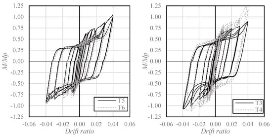
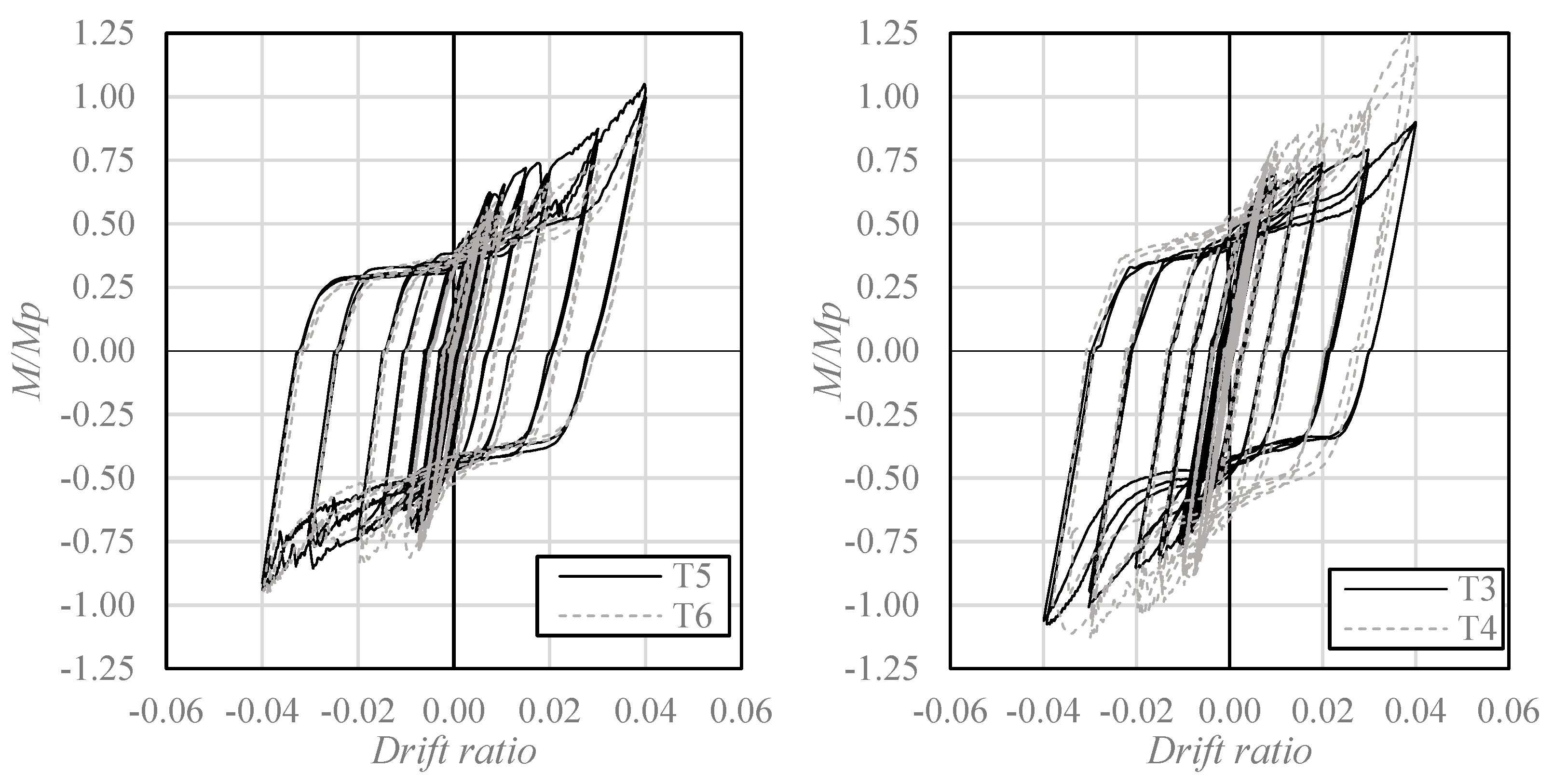
Normalized moment–rotation curves of the tested specimens with L1 = 400 mm, using six flange bolts (left) and eight flange bolts (right).
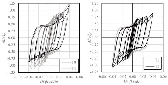
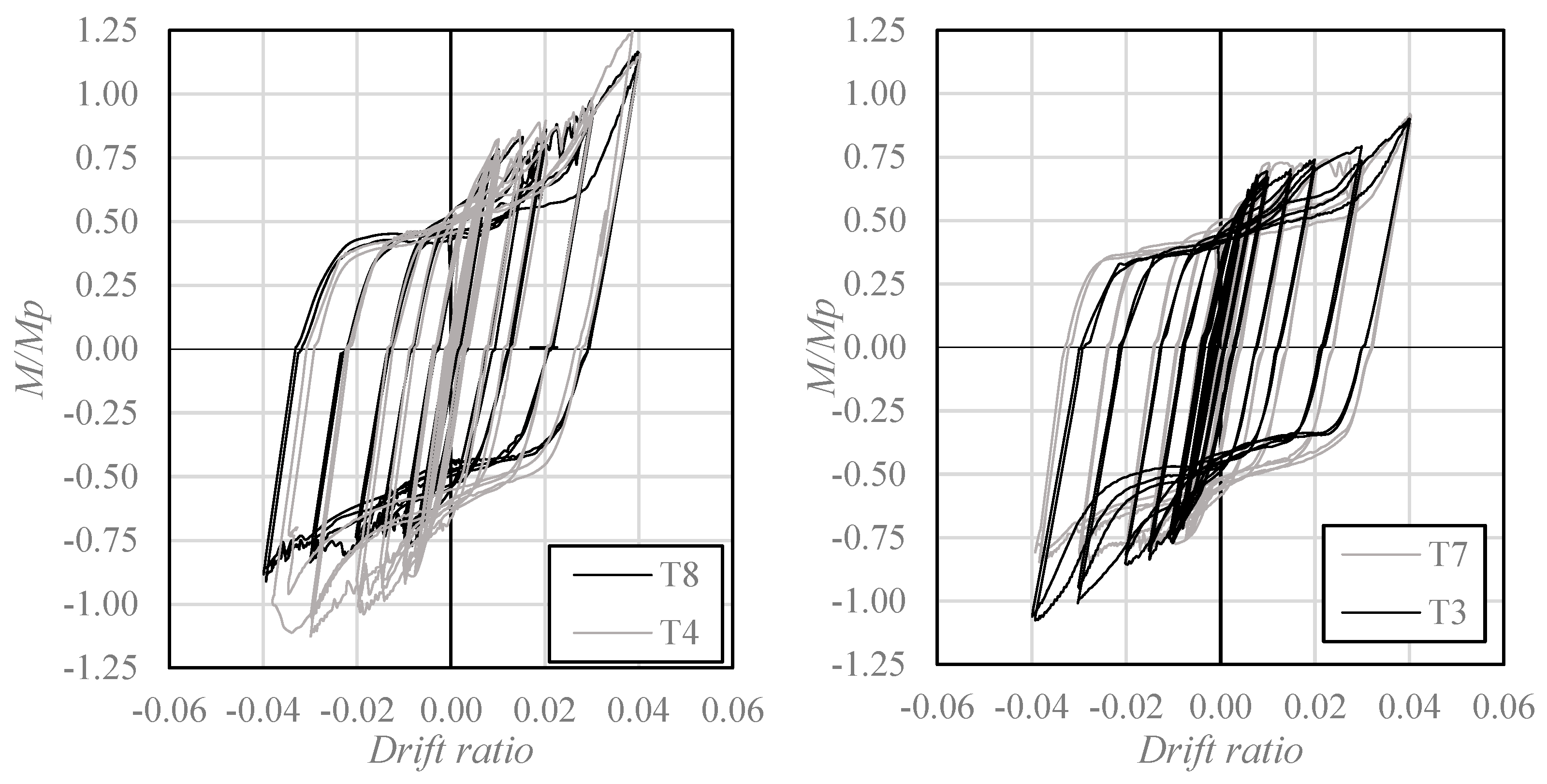
For specimens with a beam stub length of 400 mm (Figure 5), increasing the cover plate thickness produced different responses depending on bolt quantity. While the eight-bolt configuration exhibited a 19.7% increase in peak moment resistance (T3–T4), the six-bolt configuration showed an 8.9% reduction (T5–T6). Therefore, increasing cover plate thickness did not consistently improve peak resistance across all investigated configurations.
The results presented in Figure 5 further illustrate the interaction between cover plate thickness and bolt quantity. For the six-bolt configurations, both plate thicknesses developed comparable peak moments, although the 8 mm plate configuration (T5) reached a slightly higher resistance than the 10 mm configuration (T6). In contrast, for the eight-bolt configurations, the thicker plates developed higher peak moments, with increases of 19.7% and 26.7% for stub lengths of 400 and 300 mm, respectively.
Overall, the experimental results demonstrate that cover plate thickness influences the cyclic resistance of the proposed connections, but its effect depends on the combination of geometric and connection parameters. Consequently, the selection of cover plate thickness should be considered together with bolt quantity and beam stub length when evaluating the intended damage-control mechanism.
3.2. Effect of Bolt Quantity
The influence of bolt quantity on the cyclic performance of the proposed column-tree connections is illustrated in Figure 6. For specimens with a stub length of 300 mm and 10 mm cover plates, increasing the number of flange bolts from six to eight increased the peak moment resistance by 12.9% (T1–T8). In contrast, for the corresponding configurations with 8 mm cover plates, the peak resistance decreased by 3.3% (T2–T7). These results indicate that the effect of additional bolts on peak moment resistance depends on cover plate thickness.
Figure 6.
Normalized moment–rotation curves of the tested specimens with L1 = 300 mm, using tp = 10 mm (left) and tp = 8 mm (right).
The differences between the configurations investigated suggest that increasing bolt quantity does not necessarily result in a proportional improvement in connection strength. Although additional bolts increase the potential frictional resistance and load-transfer capacity of the splice, the resulting cyclic response also depends on the deformation and bearing behavior of the cover plates.
A similar interaction is observed in Figure 7 for specimens with a beam stub length of 400 mm. With 10 mm cover plates, increasing the number of flange bolts from six to eight increased the peak moment resistance by 34.8% (T6–T4). However, when the cover plate thickness was reduced to 8 mm, the corresponding increase was limited to 2.5% (T5–T3). These results indicate that the contribution of additional bolts to peak strength was more pronounced in the configurations incorporating thicker cover plates.
Figure 7.
Normalized moment–rotation curves of the tested specimens with L1 = 400 mm, using tp = 10 mm (left) and tp = 8 mm (right).
Overall, the experimental findings demonstrate that bolt quantity and cover plate thickness have a combined influence on connection resistance. Within the investigated configurations, increasing bolt quantity generally enhanced peak moment resistance, although the magnitude and direction of this effect varied with plate thickness. This interaction highlights the importance of considering both parameters when evaluating the cyclic performance and damage-control characteristics of the proposed connection.
3.3. Effect of Beam Stub Length
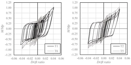
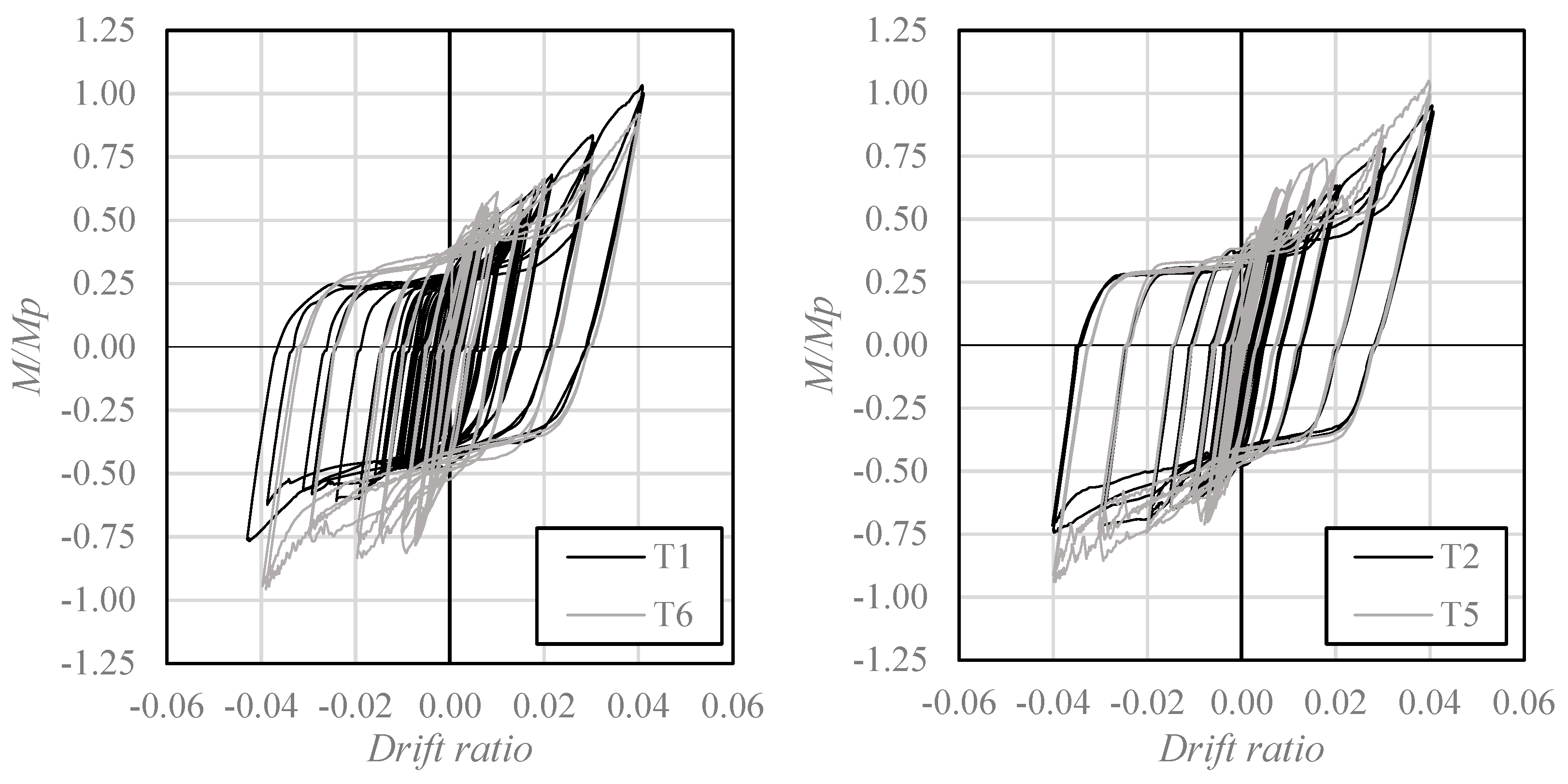
Figure 8 and Figure 9 illustrate the influence of beam stub length on the cyclic response of the investigated connections. Increasing the stub length from 300 to 400 mm increased the peak moment resistance by 10.3% for specimens T2–T5, 16.9% for T7–T3, and 10.5% for T8–T4. However, a 7.4% reduction was observed for specimens T1–T6. These results indicate that the influence of beam stub length on peak resistance is configuration-dependent and does not follow a uniform increasing trend.
Figure 8.
Normalized moment–rotation curves of the tested specimens with using six flange bolts tp = 10 mm (left) and tp = 8 mm (right).
Figure 9.
Normalized moment–rotation curves of the tested specimens with using eight flange bolts tp = 10 mm (left) and tp = 8 mm (right).
The experimental results indicate that the onset of slip is more strongly associated with flange bolt quantity than with beam stub length. As reported in Table 4, specimens with six flange bolts exhibited normalized slip moments ranging from 0.28 to 0.40, whereas those with eight bolts exhibited values between 0.45 and 0.49. These differences are consistent with the greater potential slip resistance associated with a larger number of pretensioned bolts. Nevertheless, variations among specimens with the same bolt quantity suggest that slip initiation may also be influenced by contact conditions and effective bolt pretension. Accordingly, the experimental results do not establish a systematic relationship between increasing beam stub length and delaying slip initiation.
These observations indicate that beam stub length influences the cyclic response of the proposed connections, although its contribution to peak moment resistance depends on the corresponding bolt arrangement and cover plate thickness. Therefore, the effect of stub length should be evaluated in conjunction with the other connection parameters rather than as an independent indicator of improved cyclic strength.
3.4. Required Connection Strength
As reported in Table 4, all eight specimens developed maximum bending moments exceeding 90% of the nominal beam plastic moment capacity, with normalized peak moment ratios ranging from 0.92 to 1.29. The highest value was recorded for specimen T4, which reached 1.29 Mp. The corresponding force–displacement responses exhibit stable, nearly parallelogram-shaped hysteretic loops, indicating a reliable and repeatable cyclic behavior without significant strength degradation within the examined deformation range.
The connections remained predominantly elastic until the joint rotation reached approximately 0.0075 rad for specimens with six bolts per flange and about 0.010 rad for those with eight bolts per flange. Beyond these rotation levels, relative slip between the connection components became the governing deformation mechanism, producing a characteristic horizontal segment in the hysteresis curves. The extent of this slip plateau is directly influenced by the number of bolts, reflecting the geometric nonlinearity associated with frictional sliding and bearing at the faying surfaces. Furthermore, the length of the plateau is bounded by the clearance of the bolt holes, which limits the maximum relative displacement prior to full bearing engagement.
For drift ratios greater than approximately 0.025 rad, the connection stiffness increased again, accompanied by clear signs of yielding in the cover plates, marking the transition to material nonlinearity and confirming the activation of the intended fuse mechanism. The influence of the slip plateau is evident in the hysteretic responses of all specimens, with more pronounced effects observed in configurations employing 10 mm thick cover plates. In contrast, specimens with 8 mm plates exhibited greater susceptibility to out-of-plane bending, which promoted earlier slip initiation and a more gradual development of the plateau region. These observations further highlight the coupled role of plate thickness and bolt quantity in governing the cyclic deformation mechanisms and overall stability of the proposed connection system.
3.5. Plastic Damage Assessment
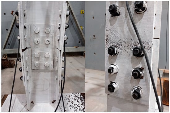
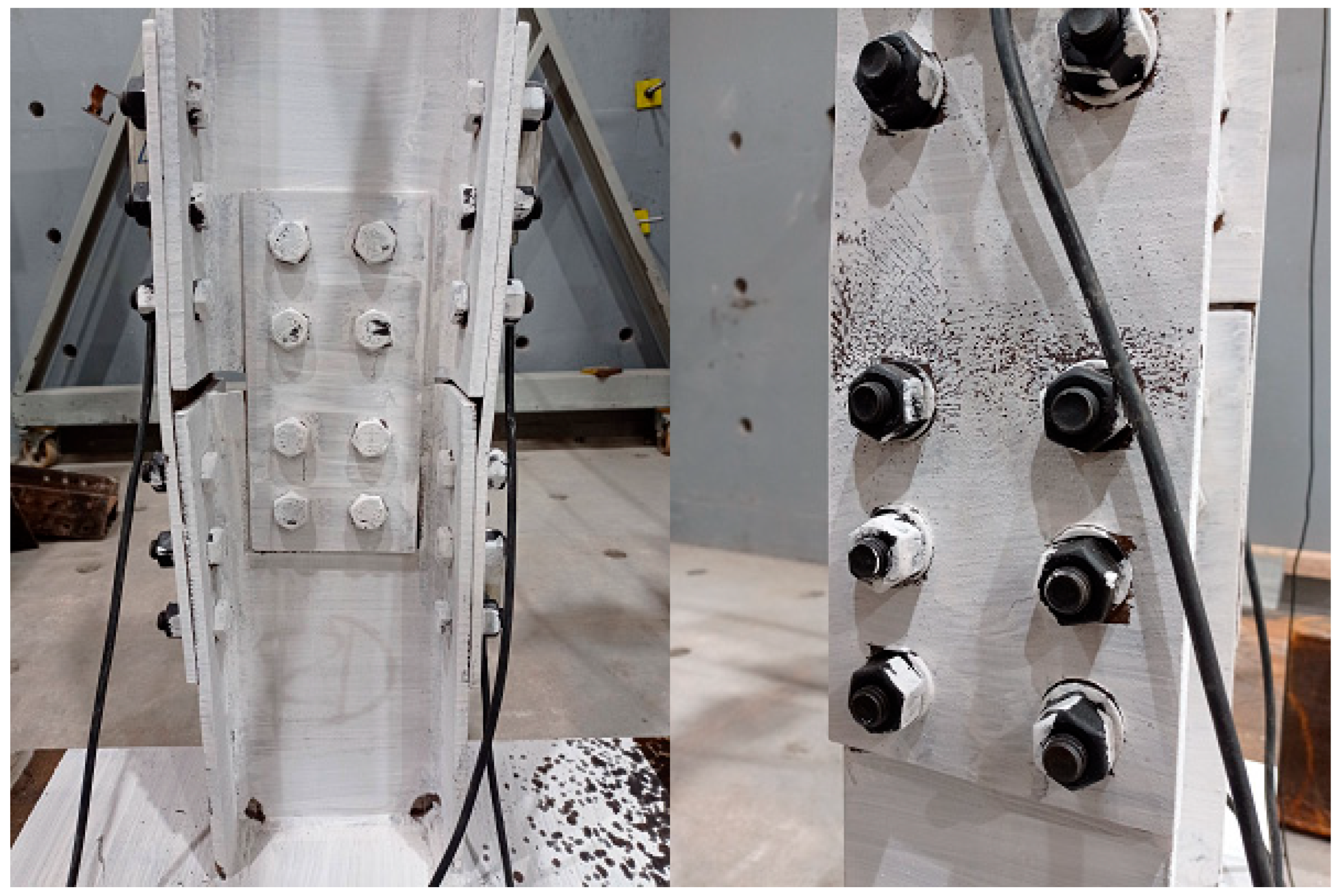
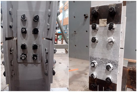
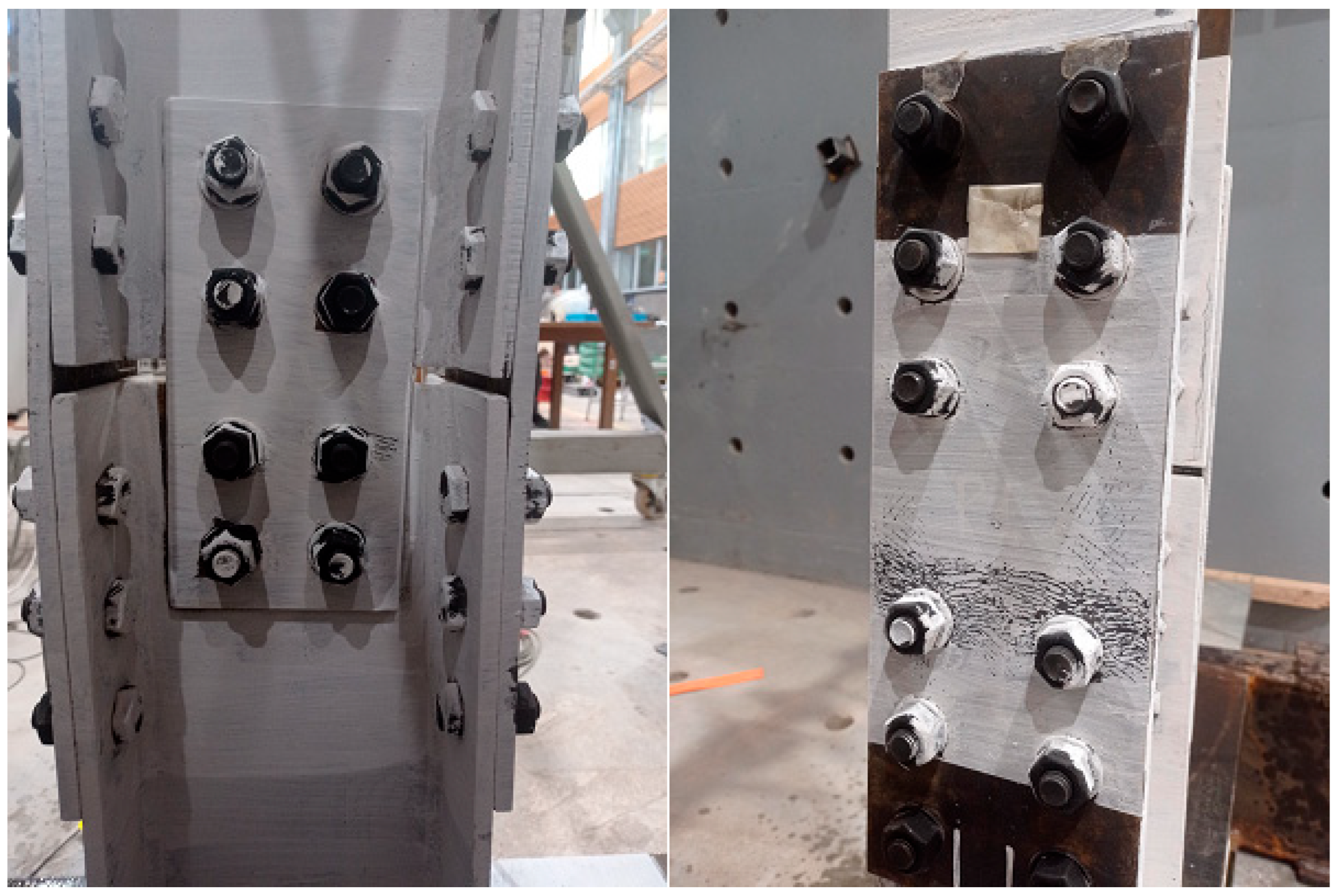
A primary objective of the proposed connection design is to limit plastic damage in the columns and beam stubs by concentrating inelastic deformation in the replaceable connection components. Upon completion of the loading protocol up to a drift ratio of 4%, post-test inspections revealed no visible flange buckling, fracture, or significant permanent deformation in the primary structural members. The beam stubs remained approximately perpendicular to the column flanges, while the observed damage was predominantly concentrated in the connection plates. Figure 10 and Figure 11 illustrate the post-test conditions of specimens T5 and T6, respectively. In both cases, the paint patterns indicate rotation of the web shear plates during the final loading cycles, consistent with deformation being accommodated primarily within the connection region.
Figure 10.
Specimen T5 at 4% rad drift.
Figure 11.
Specimen T6 at 4% rad drift.
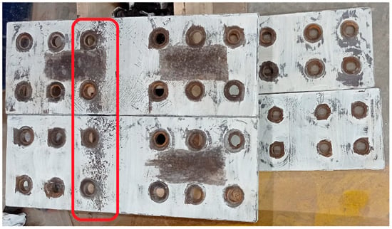
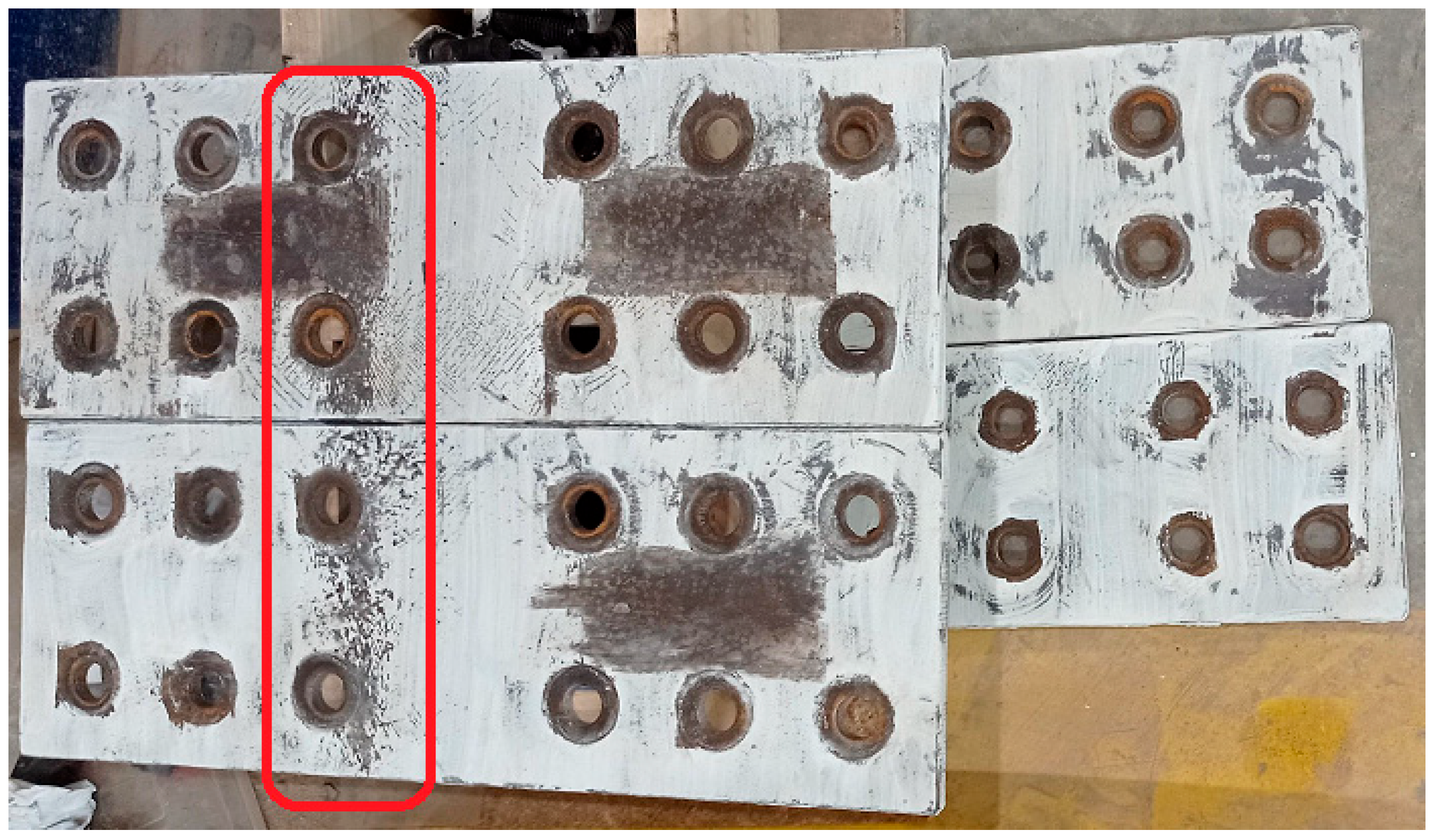
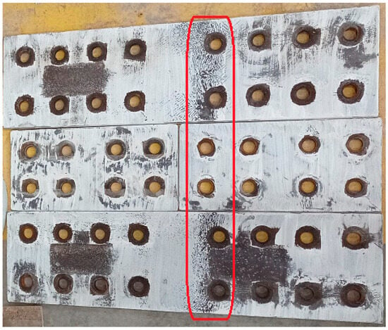
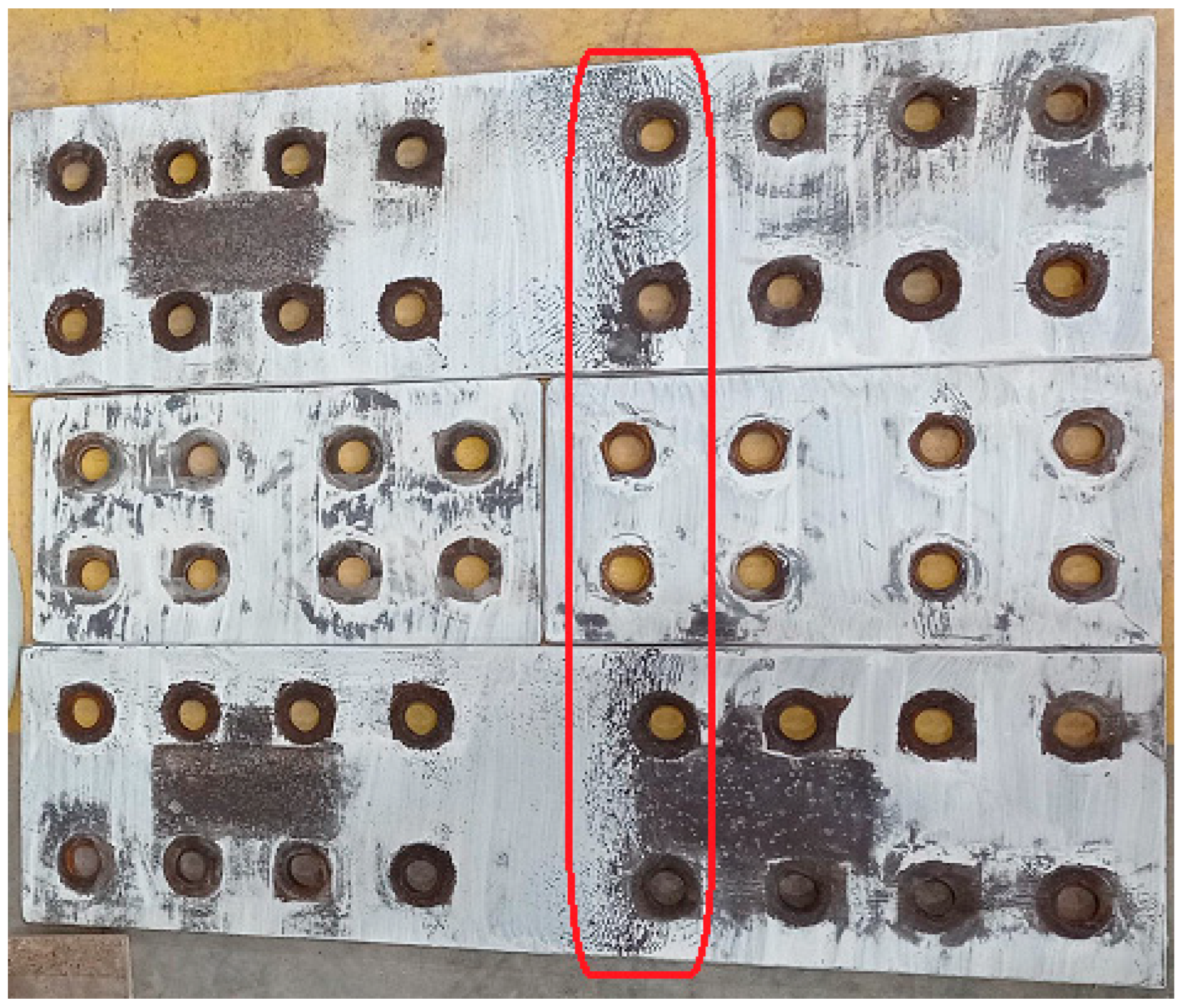
Localized yielding in the cover plates was observed near the bolt line closest to the center of the splice, as illustrated in Figure 12 and Figure 13 for specimens T2 and T3, respectively. This behavior is consistent with the intended fuse mechanism, in which inelastic deformation is preferentially concentrated in the replaceable plates. However, considering the maximum bending moments developed in specimens T4 and T8, localized yielding in the beam stubs cannot be excluded, despite the absence of visible damage. Accordingly, the experimental observations support the effectiveness of the proposed damage-localization mechanism but do not establish that the primary structural members remained strictly elastic throughout the loading history. The concentration of visible damage in the replaceable plates suggests potential advantages for post-earthquake repair strategies, although the structural condition of the primary members and the feasibility of plate replacement would require verification before reuse.
Figure 12.
Connection plates for specimen T2 (damage enclosed in red).
Figure 13.
Connection plates for specimen T3 (damage enclosed in red).
3.6. Energy Dissipation
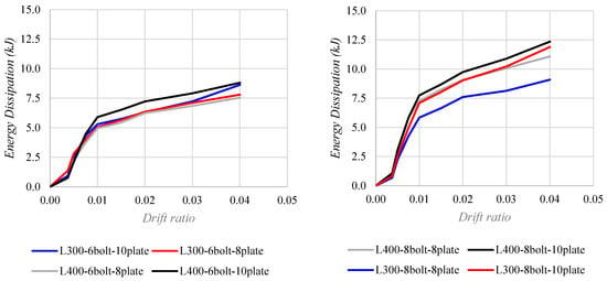
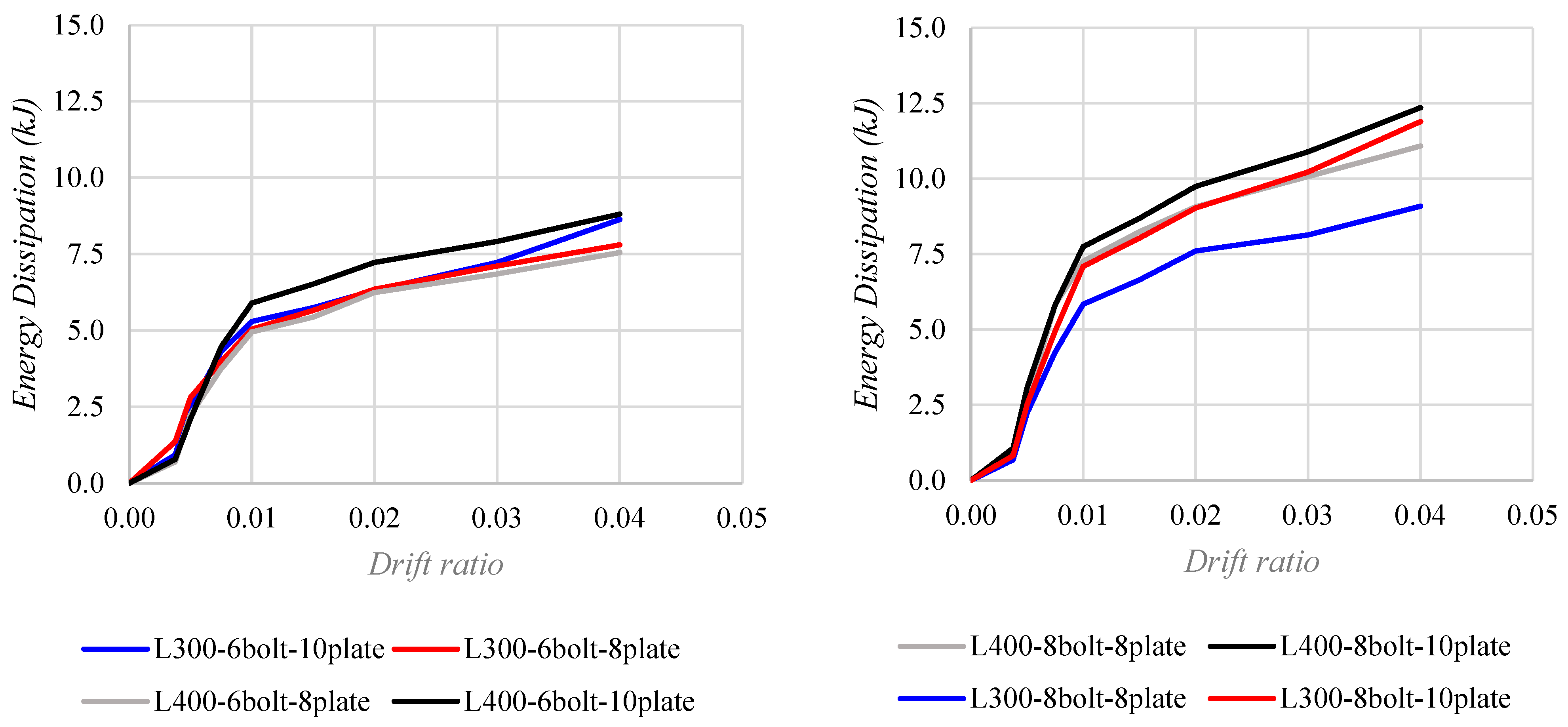
Energy dissipation in the investigated connections results from the combined effects of frictional sliding and localized plastic deformation of the replaceable cover plates. Figure 14 presents the cumulative dissipated energy for specimens with six flange bolts (left) and eight flange bolts (right). A marked increase in energy dissipation was observed within the drift range of approximately 0.375% to 1.00%, associated with the onset and development of frictional sliding at the contacting surfaces.
Figure 14.
Summary of energy dissipation for specimens tested.
At larger drift demands, progressive bolt bearing engagement restricts relative sliding and promotes localized yielding of the cover plates, providing an additional energy dissipation mechanism. Frictional sliding and plastic deformation may therefore contribute simultaneously to the hysteretic response. Since their individual contributions were not quantified separately, a specific drift threshold beyond which either mechanism becomes exclusively dominant cannot be established from the experimental results.
As reported in Table 4, the eight-bolt configurations exhibited higher cumulative energy dissipation than their corresponding six-bolt counterparts, with increases ranging from 16.4% to 46.8%. These results indicate that additional flange bolts were associated with greater energy dissipation within the investigated configurations. However, the magnitude of this improvement depended on cover plate thickness and beam stub length, and the observed increases should not be interpreted as directly proportional to the number of bolts.
Specimen T7 (L300–8bolt–8plate) exhibited lower cumulative energy dissipation than the other eight-bolt configurations. During testing, unintended relative movement was observed between the anchorage plates and the reaction concrete slab. This movement may have affected the recorded global displacement and rotation response, potentially influencing the calculated hysteretic energy dissipation. However, its magnitude and contribution to the measured response were not independently quantified. Consequently, the energy dissipation results for T7 are retained for completeness but should be interpreted with caution, particularly when assessing the influence of bolt quantity and cover plate thickness.
Table 5 summarizes the cumulative energy dissipation of all eight specimens at a drift ratio of 4%, with reported values ranging from 7.6 to 12.4 kJ. Direct comparisons between corresponding six- and eight-bolt configurations indicate increases in reported energy dissipation ranging from approximately 16% to 47%. However, the lower bound of this interval involves specimen T7, for which unintended movement of the anchorage system was observed. Excluding this comparison, the remaining three specimen pairs exhibited increases ranging from approximately 38% to 47%. Increasing cover plate thickness from 8 to 10 mm was also associated with higher reported energy dissipation, although comparisons involving T7 should be interpreted with caution.
Table 5.
Summary of total dissipated energy at 4% drift ratio.
Table 6.
Estimated apparent slip coefficient C.
These results indicate that both flange bolt quantity and cover plate thickness influence cumulative energy dissipation, although the magnitude of their contributions varies with the connection configuration. The observed response is consistent with the combined action of frictional sliding and localized plate yielding. However, the individual energy contributions of these mechanisms were not quantified separately.
The estimated apparent slip coefficients varied among the tested configurations, reflecting the combined influence of contact conditions, effective bolt pretension, and the assumptions adopted in the simplified calculation. These differences should not be interpreted as changes in the intrinsic friction properties of the contacting steel surfaces. Although increasing the number of pretensioned bolts can enhance the total slip resistance of the connection, the friction coefficient itself is not directly governed by bolt quantity. Furthermore, the estimated apparent coefficients should not be directly equated with the nominal slip coefficients specified for standardized surface conditions in AISC provisions.
In all cases, the proposed connections were able to sustain a story drift angle of at least 0.04 rad, while the bending moment measured at the column face ranged from 0.85 Mp to 1.19 Mp. All welded joints were executed as complete joint penetration (CJP) welds, and post-test inspections revealed no evidence of weld cracking or other forms of weld-related damage, further confirming the effectiveness of the damage-control design strategy.
The nominal pretension of 85 kN was used as a reference value for estimating the apparent slip coefficients. These estimates are therefore conditional on the assumed bolt pretension and should not be interpreted as measurements of the actual friction coefficient or residual clamping force. The effective pretension adopted in the finite element models is discussed separately in Section 4.1.
4. Numerical Models
4.1. Numerical Model Definition
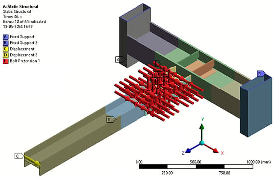
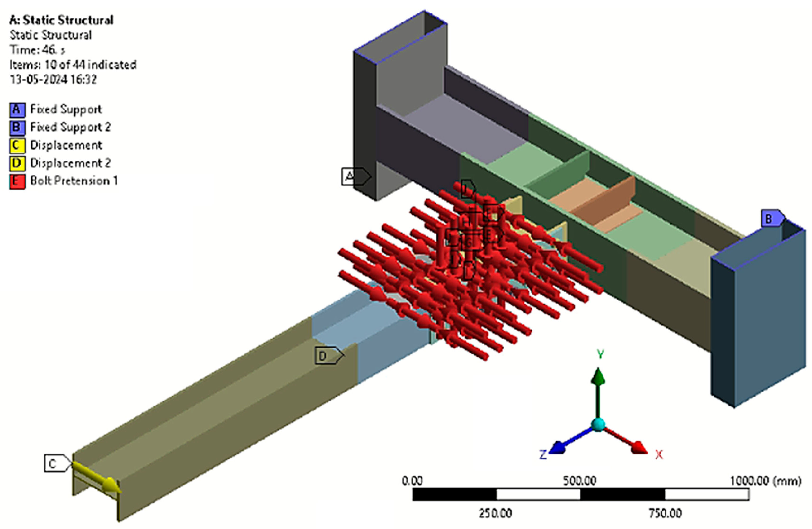
A detailed three-dimensional finite element model was developed and implemented in [33] to reproduce the experimental configurations, including their material properties, geometric dimensions, and boundary conditions, as illustrated in Figure 15. Beams, columns, cover plates, and bolts were discretized using SOLID185 eight-node solid elements, following the modeling approach previously adopted by the authors [27]. SOLID185 supports material nonlinearity, large deformations, and contact interactions, making it suitable for simulating the cyclic response of the investigated connections. Compared with the higher-order SOLID186 element, SOLID185 requires fewer degrees of freedom per element and was selected to reduce computational demand in the detailed three-dimensional models. The suitability of the adopted modeling approach was assessed through comparisons with the experimental hysteretic responses and observed deformation mechanisms.
Figure 15.
Numerical model with boundary conditions.
Welded regions were represented using bonded contact to provide displacement continuity between connected components. Contact between the bolt shanks and the surfaces of the bolt holes was modeled as frictionless, allowing relative sliding before bearing engagement. Frictional contact was assigned to the steel-to-steel interfaces between the connected plates to represent the resistance to relative sliding. A friction coefficient of μ = 0.20 was adopted for these interfaces, while μ = 0.05 was assigned to the contact between bolt nuts and plates.
The friction coefficient adopted for the steel-to-steel interfaces was informed by the experimental response and the corresponding estimates of the apparent slip coefficient presented in Table 6. These estimates are derived from the measured slip moments using the nominal bolt pretension and a simplified force-transfer formulation. Consequently, they are not directly equivalent to the local Coulomb friction coefficient used in the numerical contact model. The adopted value of μ = 0.20 was therefore treated as a modeling assumption within the calibration procedure rather than as an independently measured material property. Frictional resistance influences slip initiation, the development of the hysteretic slip plateau, and the associated energy dissipation.
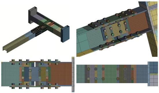
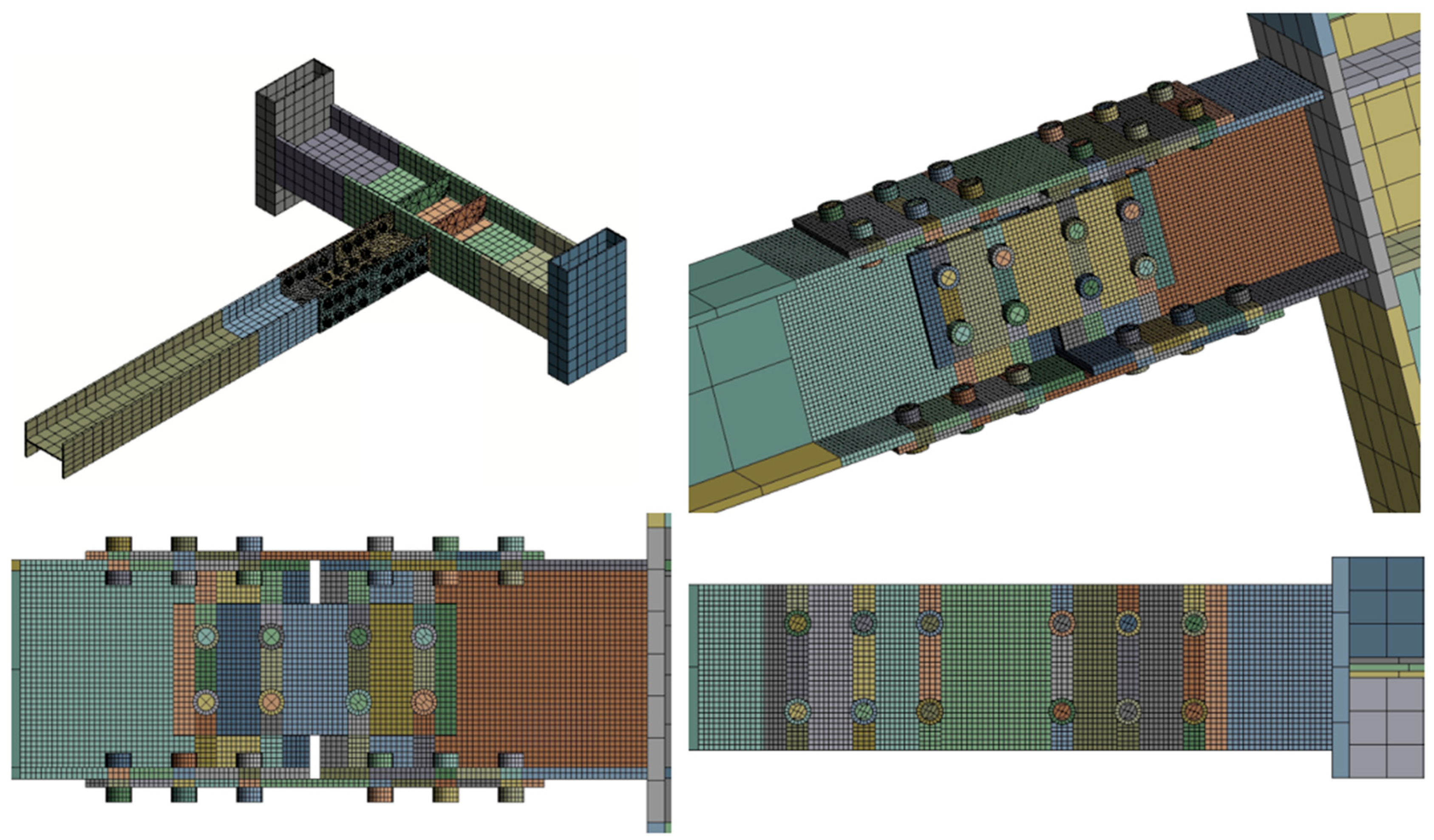
A nonuniform mesh was adopted to balance computational efficiency and the spatial resolution required in regions of concentrated nonlinear deformation. A maximum element size of 50 mm was used in regions away from the connection, whereas the mesh was refined to a maximum element size of 5 mm around the bolt holes and replaceable cover plates, where contact interactions, stress concentrations, and localized plastic deformation were expected (Figure 16).
Figure 16.
Model mesh.
During numerical calibration, the effects of bolt pretension, contact friction, and mesh refinement on the simulated cyclic response were examined. In the experimental program, a target bolt pretension of 85 kN per bolt was specified [31] and applied using the calibrated wrench method. In contrast, an effective pretension of 42.5 kN per bolt, corresponding to 50% of the nominal target, was adopted in the finite element models because it provided better overall agreement with the experimental hysteretic response, particularly in terms of initial stiffness, sliding behavior, and the subsequent development of plate yielding.
The adopted effective pretension is a numerical calibration parameter and does not represent an experimentally verified reduction in bolt force. Since residual bolt pretension was not directly measured during testing, the difference between the nominal experimental target and the calibrated numerical value cannot be conclusively attributed to pretension loss. Possible contributing factors include uncertainties in the actual clamping force, contact pressure distribution, surface conditions, and simplifications in the numerical representation of the bolted interfaces. Their individual contributions were not independently quantified.
The finite element models were calibrated against the experimental responses of the eight investigated specimens. Consequently, the numerical–experimental comparisons presented in the following section assess the agreement of the calibrated models with the available experimental data rather than providing independent validation of their predictive capabilities. The models are therefore used primarily to interpret the observed cyclic behavior and deformation mechanisms within the investigated configurations, while their predictive applicability to other connection configurations requires further verification.
4.2. Results of Numerical Models
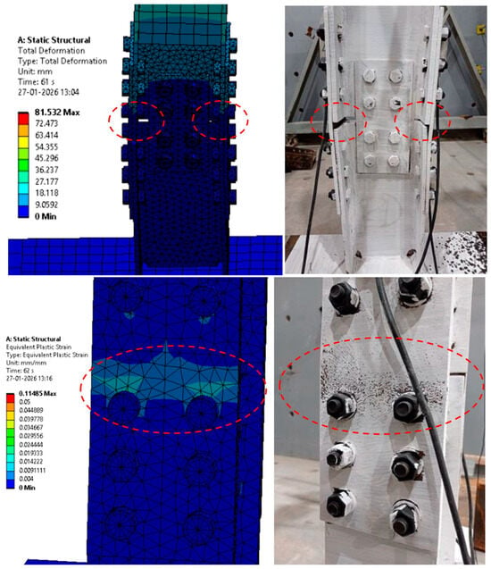
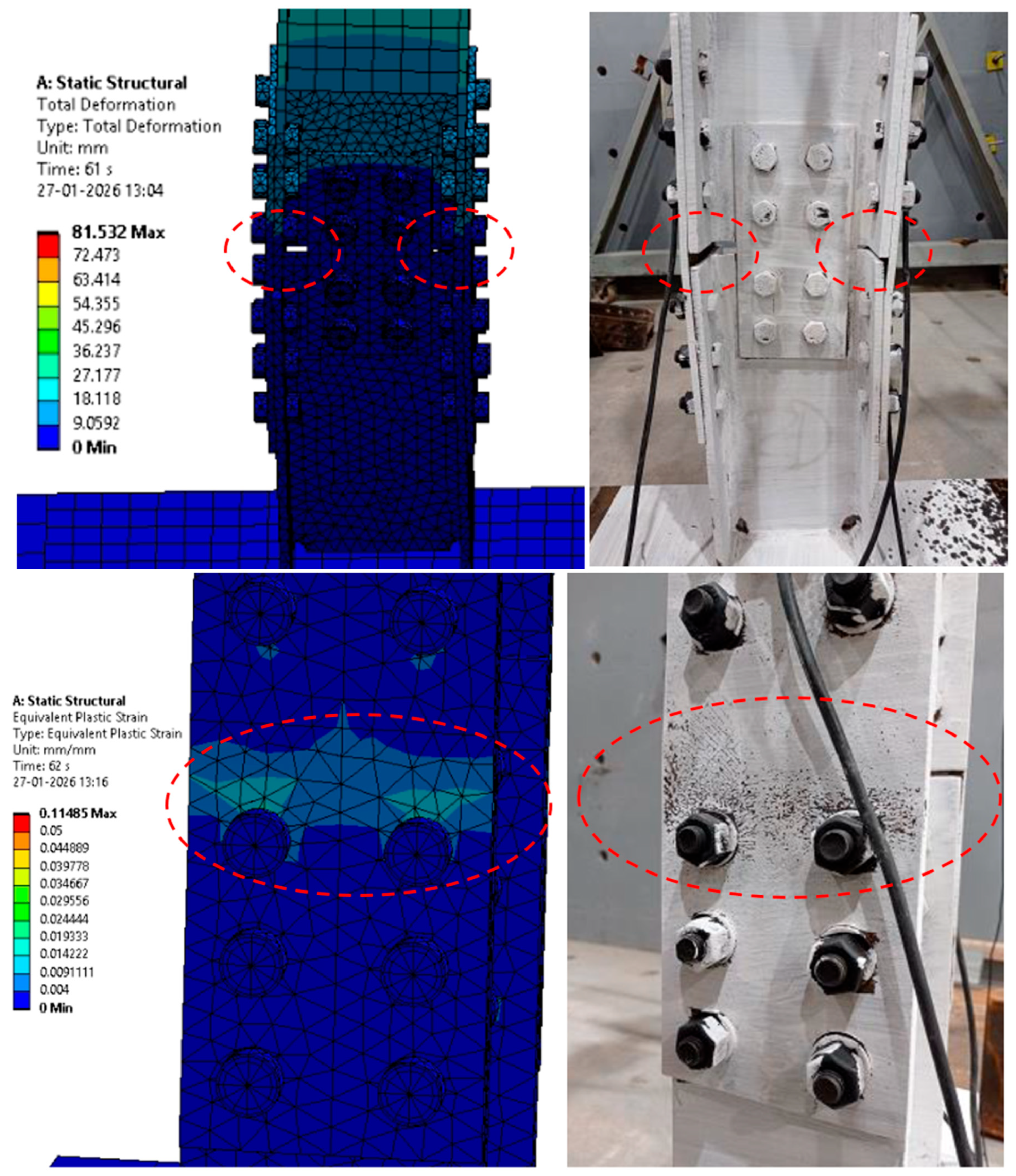
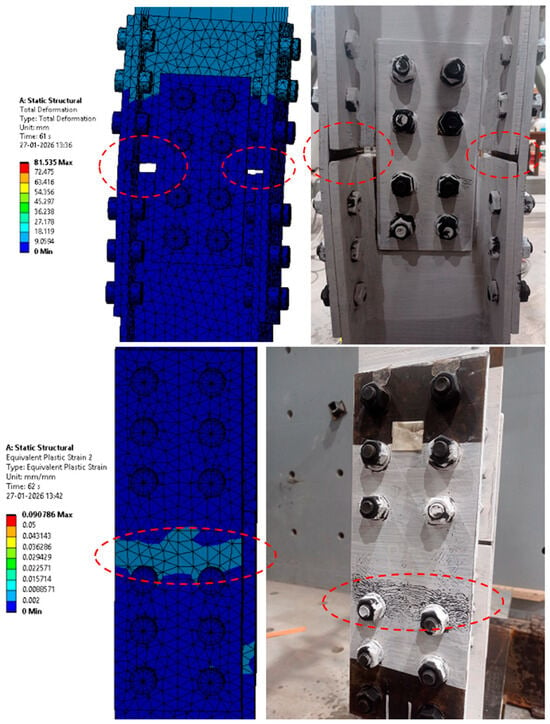
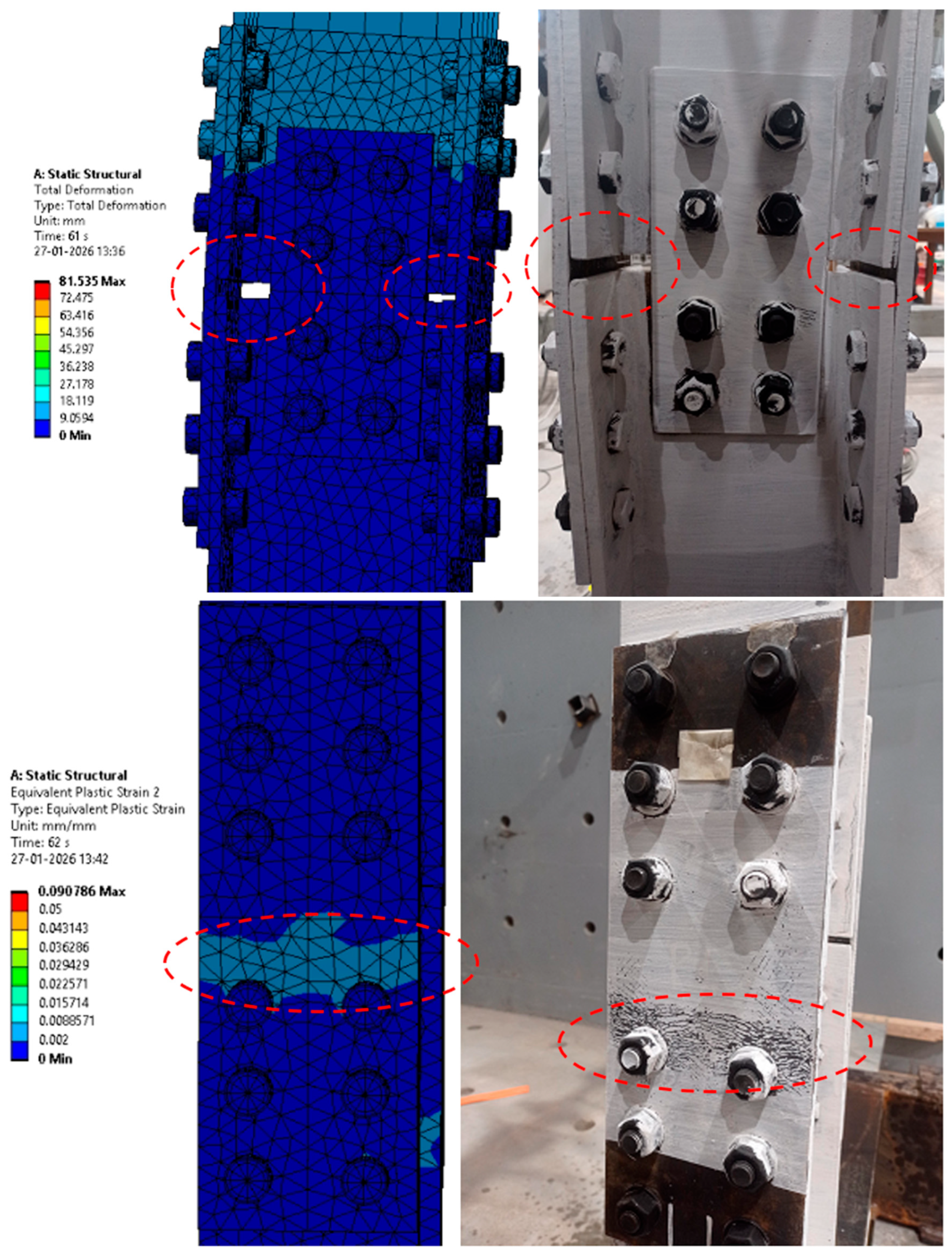
The failure mechanisms developed by the numerical models are consistent with those observed in the experimental tests. In all cases, inelastic damage was concentrated in the cover plates, while the remaining structural components remained within the elastic range. Figure 17 and Figure 18 present a direct comparison between the numerical simulations and the corresponding tested specimens.
Figure 17.
Comparison of damage for model T5 and specimen tested at 4% rad drift.
Figure 18.
Comparison of damage for model T6 and specimen tested at 4% rad drift.
As shown, the displacement demand at a drift ratio of 4% exhibits similar magnitudes in both experimental and numerical results. Moreover, the distribution of plastic deformations follows the same failure pattern, with inelasticity localized in a very similar manner within the cover plates. The equivalent plastic strain represents a scalar measure of accumulated plastic deformation obtained from the plastic strain components in the finite element model. This quantity is used to identify regions where irreversible deformation develops and to assess the localization of inelastic response within the connection components. In Figure 17 and Figure 18, the equivalent plastic strain contours are presented to illustrate the concentration of plastic deformation in the replaceable cover plates and its distribution relative to the primary structural members. This measure should be interpreted as an indicator of plastic deformation accumulation rather than a direct measure of structural damage or fracture. This close agreement confirms that the numerical model is capable of accurately reproducing not only the global cyclic response of the connection, but also the governing local damage mechanisms.
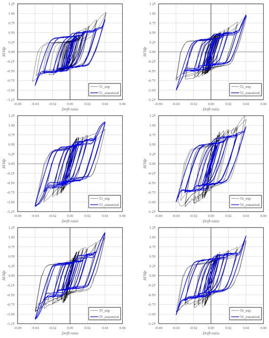
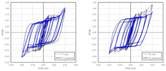
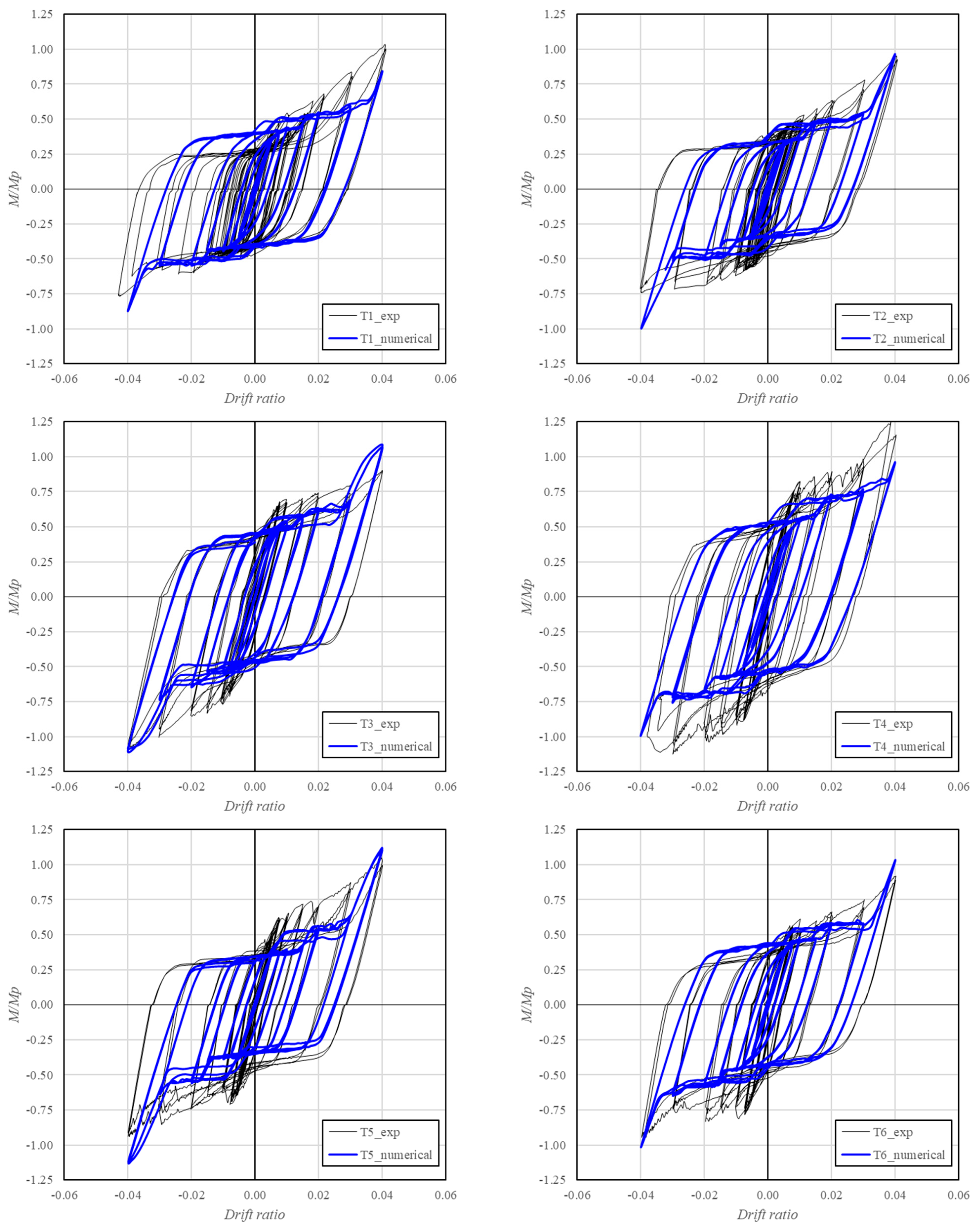
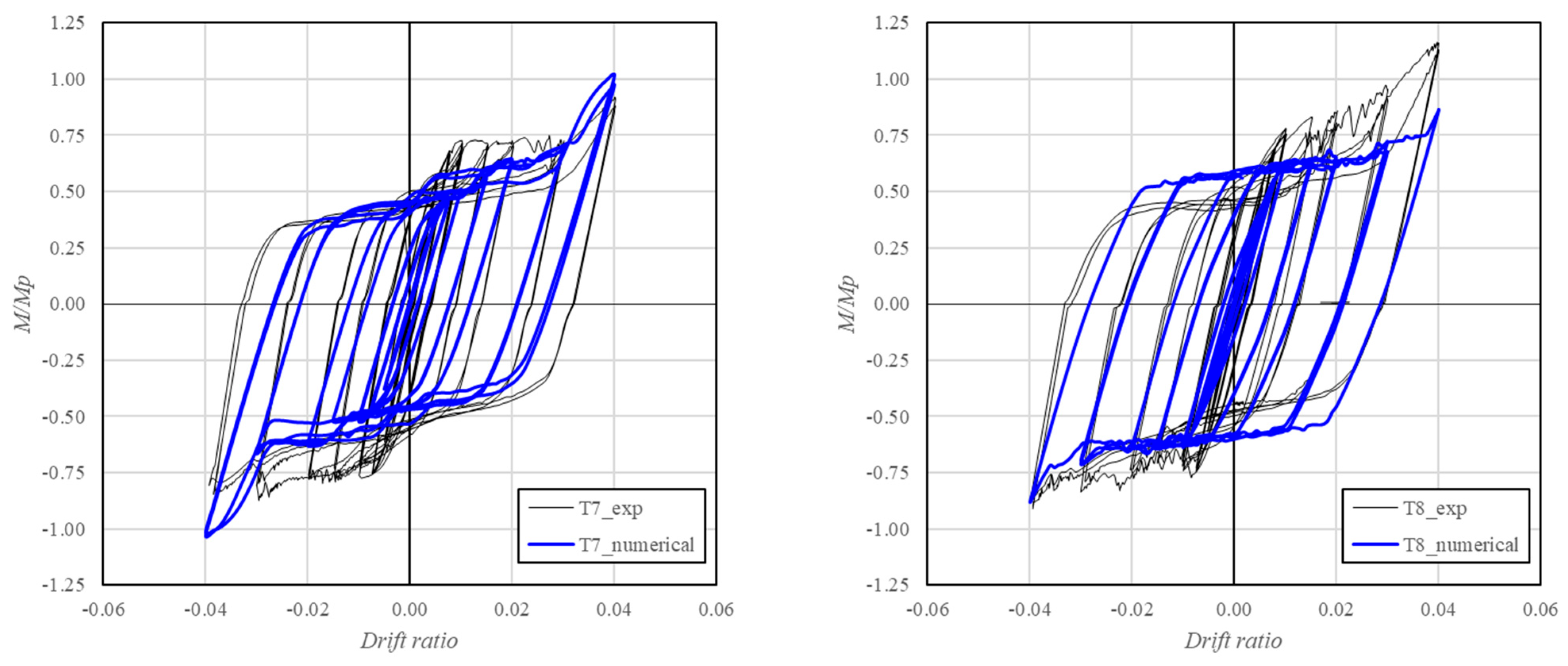
Figure 19 presents a comparison between each numerical model and its corresponding experimental specimen in terms of normalized moment–rotation response. In general, the numerical simulations exhibit a distinct plateau at the slip-load level, followed by a sharp increase in stiffness associated with bolt bearing engagement and subsequent yielding of the cover plates.
Figure 19.
Comparison between experimental (black) and numerical (blue) normalized moment–rotation responses.
Although the numerical models reproduced the main hysteretic characteristics and observed failure mechanisms, differences remained between the numerical and experimental responses, particularly in initial stiffness, slip behavior, and peak moment resistance. These discrepancies may be associated with the idealized geometric and contact conditions adopted in the finite element models. In the experimental specimens, fabrication tolerances, bolt-hole clearances, and minor geometric misalignments may produce nonuniform contact conditions and progressive bolt engagement during cyclic loading. In contrast, the numerical models assume idealized geometric alignment and simplified contact interactions, which may affect the predicted slip initiation, stiffness recovery, and peak strength. Differences in effective bolt pretension and the representation of frictional behavior may also contribute to variations in the shape and symmetry of the hysteretic loops. Nevertheless, the numerical simulations consistently reproduced the characteristic slip plateau, subsequent stiffness recovery, and concentration of plastic deformation within the replaceable cover plates. Therefore, the models provide a reasonable representation of the governing cyclic mechanisms, although their ability to reproduce the precise stiffness and strength response remains limited by the adopted contact and geometric idealizations.
However, a well-defined slip plateau governed by the onset of bolt sliding and the concentration of damage within the cover plates are consistently captured by both experimental and numerical results, confirming these features as characteristic behavioral of the proposed column-tree connection system.
The applicability of these findings is limited to the connection configurations and material properties investigated in this study. Although the observed mechanisms of frictional sliding, bolt bearing, and localized plate yielding may also occur in other bolted steel connections, their relative contributions and resulting cyclic performance may vary with member geometry, steel grade, and connection detailing. Therefore, extrapolation to other structural configurations requires further verification to establish whether inelastic deformation can be effectively confined to the replaceable cover plates while preserving the integrity of the primary structural members.
From a practical perspective, the column-tree connections investigated offer a potential alternative for damage-controlled steel moment-resisting frames by combining shop-welded beam stubs, field-bolted splices, and replaceable rectangular cover plates. This arrangement reduces the need for field welding and provides a mechanism for concentrating inelastic deformation in connection components rather than in primary structural members. The experimental observations support the feasibility of this damage-control approach within the investigated configurations, suggesting potential benefits for post-earthquake inspection and repair. However, practical implementation requires careful consideration of beam stub length, bolt arrangement, plate thickness, and contact conditions, as these parameters influence slip initiation, stiffness, strength, and energy dissipation. Furthermore, the observed concentration of damage in the cover plates does not, by itself, establish the effectiveness or duration of post-earthquake replacement procedures, which were not evaluated experimentally. The proposed connection should therefore be considered a promising damage-control solution whose broader structural application requires additional verification, including the influence of connection flexibility, dimensional scaling, and practical replacement procedures.
5. Conclusions
The cyclic performance of column-tree moment connections incorporating replaceable rectangular cover plates was investigated through eight full-scale tests and calibrated finite element simulations. The experimental program systematically examined the influence of beam stub length, flange bolt quantity, and cover plate thickness on hysteretic behavior, energy dissipation, and damage localization. The main contributions and findings are summarized as follows:
1. The experimental results demonstrated the feasibility of concentrating visible inelastic damage predominantly within conventional rectangular cover plates. All tested configurations sustained a drift ratio of 4%, with no visible flange buckling, fracture, or significant permanent deformation observed in the primary structural members. Nevertheless, localized yielding in the beam stubs cannot be excluded, particularly for specimens T4 and T8. These findings provide experimental support for the damage-control concept previously investigated numerically, while distinguishing the absence of visible damage from a fully elastic response of the primary structural members.
2. The cyclic performance was influenced by the combined effects of flange bolt quantity and cover plate thickness. Increasing the number of bolts generally improved peak moment resistance and cumulative energy dissipation, particularly in configurations incorporating 10 mm cover plates. However, the improvement in peak resistance was less pronounced or absent for some configurations with 8 mm plates. These findings indicate that bolt quantity and cover plate thickness should be evaluated jointly, as their influence on connection performance depends on the investigated configuration.
3. The influence of beam stub length on peak moment resistance was configuration-dependent, with increases observed in three of the four corresponding specimen comparisons. Regarding slip initiation, the experimental results showed a stronger association with flange bolt quantity than with stub length. Specimens with six flange bolts exhibited normalized slip moments ranging from 0.28 to 0.40, whereas those with eight bolts exhibited values between 0.45 and 0.49. These findings highlight the combined influence of splice location and bolt arrangement on the cyclic response of the investigated connections.
4. Two principal energy dissipation mechanisms were identified: frictional sliding and localized yielding of the replaceable cover plates. Frictional sliding contributed to the initial hysteretic response, producing a characteristic slip plateau, while progressive bolt bearing engagement and plate yielding contributed to energy dissipation at larger deformation demands. Both mechanisms may operate simultaneously, and their individual contributions to the total dissipated energy were not quantified separately.
5. The calibrated finite element models reproduced the principal hysteretic characteristics and the observed concentration of deformation within the replaceable cover plates. Nevertheless, discrepancies remained in stiffness, slip initiation, and peak moment resistance. These differences may be associated with geometric tolerances, effective bolt pretension, and contact modeling assumptions, although their individual contributions were not quantified. Accordingly, the numerical–experimental comparisons demonstrate agreement within the calibration dataset rather than independent predictive validation.
6. The study provides experimental evidence supporting the potential application of conventional bolted cover plates as replaceable dissipative components in column-tree moment connections. The findings also identify important design considerations related to splice location, plate thickness, and bolt arrangement. However, broader application requires further verification for different section geometries, steel grades, connection details, and post-earthquake replacement procedures.
Author Contributions
Conceptualization, E.N.; methodology, E.N. and J.C.V.P.; software, P.M., E.N., R.M., S.F.; validation, P.M. and E.N.; formal analysis, P.M. and E.N.; investigation, P.M. and E.N.; resources, J.C.V.P., G.B. and M.C.-D.; data curation, P.M. and E.N.; writing—original draft preparation, E.N. and J.C.V.P.; writing—review and editing, E.N. and J.C.V.P.; visualization, E.N.; supervision, E.N.; project administration, E.N.; funding acquisition, E.N. and F.S. All authors have read and agreed to the published version of the manuscript.
Funding
This research received no external funding.
Data Availability Statement
The data presented in this study are available on request from the corresponding author.
Acknowledgments
The authors gratefully acknowledge the Directorate of Postgraduate Studies at Universidad Católica de la Santísima Concepción (UCSC) for providing the doctoral scholarship that supported this research. The authors also thank Armin Gallardo and Diego Melo for their technical assistance during the experimental testing.
Conflicts of Interest
The authors declare no conflicts of interest.
References
- FEMA 355. State of the Art Report on Connection Performance; Federal Emergency Management Agency: Washington, DC, USA, 2000. [Google Scholar]
- Astaneh-Asl, A. Seismic Design of Steel Column-Tree Moment-Resisting Frames; Structural Steel Educational Council: Moraga, CA, USA, 1997. [Google Scholar]
- McMullin, K.M.; Astaneh-Asl, A. Steel Semirigid Column–Tree Moment Resisting Frame Seismic Behavior. J. Struct. Eng. 2003, 129, 1243–1249. [Google Scholar] [CrossRef] [Scilit]
- Chen, C.C.; Lin, C.C.; Lin, C.H. Ductile moment connections used in steel column-tree moment-resisting frames. J. Constr. Steel Res. 2006, 62, 793–801. [Google Scholar] [CrossRef] [Scilit]
- Lee, K.; Li, R.; Jung, H.; Chen, L.; Oh, K. Cyclic testing of weak-axis steel moment connections. Steel Compos. Struct. 2013, 15, 507–518. [Google Scholar] [CrossRef] [Scilit]
- Sotirov, P.; Rangelov, O.; Georgiev, T.; Petkov, Z.; Milev, J. Improved Beam-to-Column Joints for Moment-Resisting Frames—An Experimental Study; Stability and Ductility of Steel Structures; RECOS Progress Report; University of Sofia: Sofia, Bulgaria, 1999. [Google Scholar]
- Sotirov, P.; Rangelov, N.; Milev, J. Improvement of seismic behaviour of beam-to-column joints using tapered flanges. In Behaviour of Steel Structures in Seismic Areas; CRC: Boca Raton, FL, USA, 2021. [Google Scholar] [CrossRef] [Scilit]
- Chen, C.C.; Lin, C.C. Seismic performance of steel beam-to-column moment connections with tapered beam flanges. Eng. Struct. 2013, 48, 588–601. [Google Scholar] [CrossRef] [Scilit]
- Oh, K.; Li, R.; Chen, L.; Hong, S.B.; Lee, K. Cyclic testing of steel column-tree moment connections with weakened beam splices. Int. J. Steel Struct. 2014, 14, 471–478. [Google Scholar] [CrossRef] [Scilit]
- Lee, K.; Li, R.; Chen, L.; Oh, K.; Kim, K.S. Cyclic testing of steel column-tree moment connections with various beam splice lengths. Steel Compos. Struct. 2014, 16, 221–231. [Google Scholar] [CrossRef] [Scilit]
- Oh, K.; Lee, K.; Chen, L.; Hong, S.B.; Yang, Y. Seismic performance evaluation of weak axis column-tree moment connections with reduced beam section. J. Constr. Steel Res. 2015, 105, 28–38. [Google Scholar] [CrossRef] [Scilit]
- Oh, K.; So, J.; Ha, H.; Lee, K. Seismic performance evaluation of Korean column-tree steel moment connections. Int. J. Steel Struct. 2016, 16, 1287–1298. [Google Scholar] [CrossRef] [Scilit]
- Pan, J.R.; Wang, Z.; Zheng, L.Q.; Yang, Z.T. Finite element analysis of beam-column connection with cantilever beam splicing. Adv. Mater. Res. 2014, 838–841, 540–544. [Google Scholar] [CrossRef] [Scilit]
- Vatansever, C.; Kutsal, K. Effect of bolted splice within the plastic hinge zone on beam-to-column connection behavior. Steel Compos. Struct. 2018, 28, 767–778. [Google Scholar] [CrossRef]
- Zhang, A.; Guo, Z.; Liu, X. Seismic performance of Z-type cantilever beam splices of column–tree connection. J. Constr. Steel Res. 2017, 133, 97–111. [Google Scholar] [CrossRef] [Scilit]
- Gharebaghi, R.; Hosseini, A. Local behavior of column-tree connections with considering bolt-hole clearance and bolt pretension effects. Int. J. Steel Struct. 2017, 17, 379–388. [Google Scholar] [CrossRef] [Scilit]
- Karami, B.; Hashemi, B.H.; Ramhormozian, S.; Zarabimanesh, Y. Numerical study on prequalification and cyclic performance of column-tree connections. Structures 2022, 41, 331–348. [Google Scholar] [CrossRef] [Scilit]
- Xu, Y.L.; Hao, J.P.; Su, Y.X.; Shang, Y.F. Seismic Performance of Column-Tree Moment Connections with Slit Dampers. KSCE J. Civ. Eng. 2022, 26, 2789–2798. [Google Scholar] [CrossRef] [Scilit]
- Jiang, Z.Q.; Yan, T.; Zhang, A.L.; Yang, X.F.; Yu, C.; Li, R. Experimental study of plate-buckling type earthquake-resilient prefabricated steel beam-column joints with replaceable double flange cover plates. Structures 2023, 50, 1100–1113. [Google Scholar] [CrossRef] [Scilit]
- Feng, Y.; Wen, H.; Chong, X.; Jiang, Q.; Zhang, Z.; Wei, M. Experimental Study on a Single-Sided Column–Tree Connection with a Replaceable Buckling-Restrained Cover Plate at a Bottom Flange. J. Struct. Eng. 2023, 149, 04023155. [Google Scholar] [CrossRef] [Scilit]
- Xu, Y.; Su, Y.; Shang, Y.; Tian, L. Seismic performance of earthquake-resilient prefabricated corrugated web beam-column connection with buckling-restrained plates. J. Constr. Steel Res. 2022, 194, 107327. [Google Scholar] [CrossRef] [Scilit]
- Oyguc, R.; Bozan, A.B. Enhancing Seismic Repairability of Precast RC Frames Through an Innovative Replaceable Plastic Hinge Technology. Appl. Sci. 2025, 15, 5629. [Google Scholar] [CrossRef] [Scilit]
- Oyguc, E.; Oyguc, R.; Hayir, A.; Seker, O.; Shen, J.; Akbas, B. Seismic retrofitting of substandard RC frames using tube-in-tube buckling-restrained braces: Shake table evaluation and field insights. Bull. Earthq. Eng. 2025, 23, 4565–4608. [Google Scholar] [CrossRef] [Scilit]
- Di Benedetto, S.; Francavilla, A.B.; Latour, M.; Piluso, V.; Rizzano, G. Experimental response of a large-scale two-storey steel building equipped with low-yielding friction joints. Soil Dyn. Earthq. Eng. 2022, 152, 107022. [Google Scholar] [CrossRef] [Scilit]
- Valente, M.; Castiglioni, C.A.; Kanyilmaz, A. Dissipative devices for earthquake resistant composite steel structures: Bolted versus welded solution. Bull. Earthq. Eng. 2016, 14, 3613–3639. [Google Scholar] [CrossRef] [Scilit]
- Valente, M.; Castiglioni, C.A.; Kanyilmaz, A. Numerical investigations of repairable dissipative bolted fuses for earthquake resistant composite steel frames. Eng. Struct. 2017, 131, 275–292. [Google Scholar] [CrossRef] [Scilit]
- Matthews, P.; Núñez, E. Cyclic Behavior of the Column-Tree Moment Connection with Weakened Plates: A Numerical Approach. Buildings 2023, 13, 2908. [Google Scholar] [CrossRef] [Scilit]
- ANSI/AISC 358-22; Prequalified Connections for Special and Intermediate Steel Moment Frames for Seismic Applications. American Institute of Steel Construction (AISC): Chicago, IL, USA, 2022.
- ANSI/AISC 341-22; Seismic Provisions for Structural Steel Buildings. American Institute of Steel Construction (AISC): Chicago, IL, USA, 2022.
- ASTM A36; Standard Specification for Carbon Structural Steel. ASTM International: West Conshohocken, PA, USA, 2019.
- ANSI/AISC 360-22; Specification for Structural Steel Buildings. American Institute of Steel Construction (AISC): Chicago, IL, USA, 2022.
- ASTM A325; Standard Specification for Structural Bolts, Steel, Heat Treated, 120/105 ksi Minimum Tensile Strength. ASTM International: West Conshohocken, PA, USA, 2009.
- ANSYS v24, ANSYS Inc., 2024. Available online: https://ansys.synopsys.com/webinars/ansys-2024-r1-mechanical-whats-new (accessed on 18 December 2026).

Disclaimer/Publisher’s Note: The statements, opinions and data contained in all publications are solely those of the individual author(s) and contributor(s) and not of MDPI and/or the editor(s). MDPI and/or the editor(s) disclaim responsibility for any injury to people or property resulting from any ideas, methods, instructions or products referred to in the content. |
© 2026 by the authors. Licensee MDPI, Basel, Switzerland. This article is an open access article distributed under the terms and conditions of the Creative Commons Attribution (CC BY) license.