


Abstract
Large-diameter rigid piles often serve as foundations on sloping ground, where combined lateral force and overturning moment constitute important design considerations. While bearing-capacity envelope approaches have been developed for rigid piles in clay, corresponding theoretical methods for piles in sand remain relatively limited, despite the strong influence of overburden pressure and slope effects on their lateral resistance. This study extends the previous six-mode methodology to develop a theoretical framework for the - capacity envelope of large-diameter rigid piles embedded in sandy slopes. The proposed method adopts the previously established failure wedge model, incorporating a variable wedge base angle and equivalent-depth correction, and extends its unidirectional formulation to account for uphill and downhill resistance through the sign of the slope angle. Additional resistance components, including distributed vertical shear-induced moment, base shear, and base moment, are incorporated to account for the size effects of large-diameter piles. The complete - envelope is constructed from parametric equations corresponding to six soil-pile interaction models. Comparisons with finite element limit analyses and independent experimental and numerical results show reasonable agreement within the investigated conditions. Parametric analyses indicate that, within the parameter ranges considered, the fan angle has a more pronounced influence on the envelope than the interface friction angle, while the additional resistance components become increasingly relevant with increasing pile diameter and decreasing length-to-diameter ratio. The slope angle progressively increases the asymmetry of the - envelope; in the investigated case with a slope angle of , the Q2 and Q4 regions account for 89.9% and 6.3% of the total envelope area, respectively. The proposed framework provides a relatively simple theoretical approach for estimating the ultimate - capacity of rigid piles on sandy slopes and may serve as a useful reference for preliminary assessment and design, where available analytical guidance remains limited.
1. Introduction
Piles are among the most widely used foundation types in civil engineering. They serve as support for highway bridges, railway bridges, transmission towers, wind turbines, and many other structures. In such applications, piles are often required to resist not only vertical loads, but also significant lateral loads and overturning moments induced by wind, water currents, traffic, and other environmental actions. Additionally, many of these piles are designed with large diameters and relatively small length-to-diameter ratios, or are installed in soft strata. As a result, they exhibit a relatively high pile-soil stiffness ratio. According to Poulos and Hull [1], a pile is classified as rigid when , where is the bending stiffness of the pile; is the elastic modulus of the soil; and is the embedded length. Such rigid piles undergo rigid rotation under lateral and overturning loads, with negligible flexural deformation.
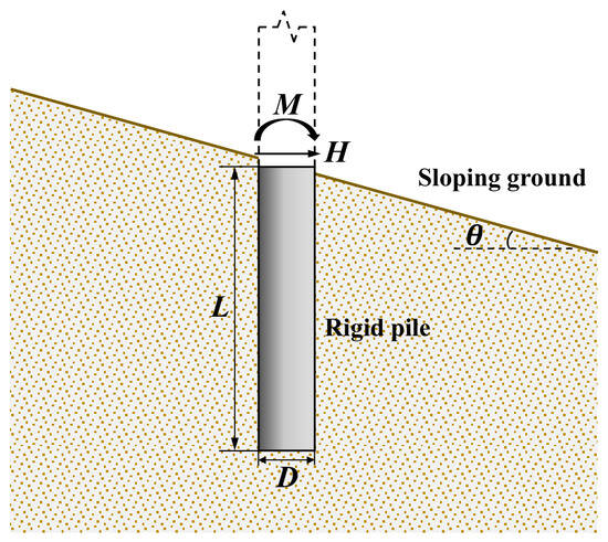
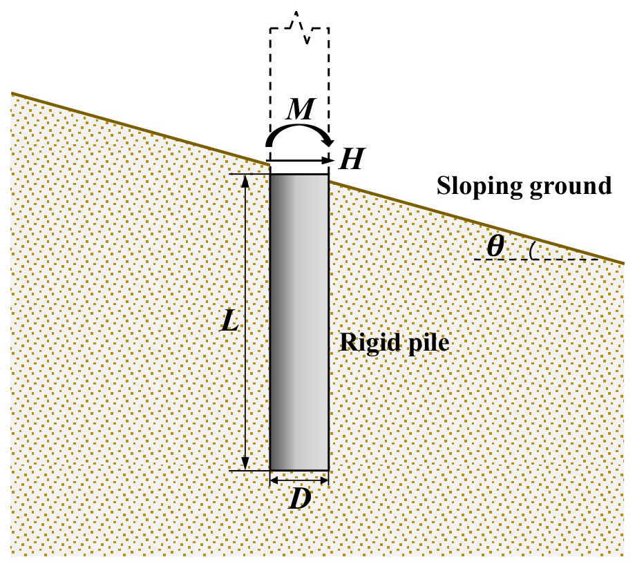
Notably, as many engineering projects are planned in or inevitably traverse topographically complex areas, an increasing number of these rigid pile foundations are unavoidably constructed on sloping ground rather than on level terrain (see Figure 1). In the figure, denotes the pile embedded length; the pile diameter; the horizontal load (positive in the downhill direction); the moment load (positive clockwise); and the slope inclination angle. This situation introduces additional challenges to their design and safety assessment. Consequently, the influence of the slope effect on the lateral bearing behavior of piles has become a topic of considerable research interest [2,3,4,5,6].
Figure 1.
Schematic of a rigid pile installed on sloping ground under combined horizontal-moment loading.
Numerous valuable studies have explored the influence of slopes on the lateral response of piles. These include laboratory tests [4,7,8], field tests [9,10,11], and numerical simulations [5,6,12,13,14]. Collectively, these efforts have enhanced our understanding of the underlying mechanism: the presence of a slope reduces the soil confinement when the pile displaces towards the downhill direction, leading to a decrease in soil resistance and consequently a reduction in both lateral stiffness and strength of the soil-pile system. However, most of these studies focused on piles adjacent to slopes and subjected to loading towards the slope direction.
For foundations under combined loading, constructing a complete bearing capacity envelope—also referred to as a failure envelope—is a state-of-the-art approach that has been recommended and advocated by many researchers [15,16,17,18]. This method is particularly attractive because it encompasses a wider range of possible load directions and combinations that are likely to occur in practice. For rigid piles on level ground, several studies on bearing capacity envelopes are available [19,20,21,22,23]. In contrast, research on capacity envelopes for rigid piles under sloping conditions remains much more limited.
Bian et al. [24] employed an inclined ellipse with its center offset from the origin to capture the - capacity envelope for piles near sandy slopes, based on two sets of finite element analyses (FEA). Their work revealed the asymmetric nature of the envelope induced by the slope. However, owing to the limited number of FEA cases, they did not provide general expressions. You et al. [25] integrated artificial neural networks (ANNs) with FEA results to investigate the capacity envelope of monopiles embedded in sandy slopes under - loading, taking into account the effects of length-to-diameter ratio and slope angle. Nevertheless, their fitted formulas lack a theoretical basis, and their applicability beyond the specific soil profiles adopted in the FEA remains questionable. Shao et al. [26], in contrast, developed a theoretical framework grounded in numerical observations and further provided a theoretical solution for the - capacity envelope of rigid monopiles near clay slopes. Their method is built on a solid theoretical foundation, effectively captures the inherent asymmetry of the envelope, and also accounts for the size effects of large-diameter piles, representing an appreciable advancement over previous studies.
Compared with the case of piles adjacent to slopes, piles installed directly on sloping ground are influenced by the slope on both sides, which inevitably induces a more pronounced slope effect and gives rise to a more significant asymmetry in the - capacity envelope, thereby introducing additional complexity to the problem. Moreover, the strength of sand is more dependent on the overburden pressure than that of clay, making the lateral capacity of piles in sand more susceptible to slope effects. This is expected to further amplify the asymmetry of the envelope under sloping conditions, and consequently calls for greater caution in the design of pile foundations on sandy slopes than in their clayey counterparts.
In light of these considerations, the present study extends the modeling framework of Shao et al. [26] from the case of piles near clay slopes to that of piles installed directly on sandy slopes, establishing a theoretical method for predicting the - capacity envelope of large-diameter rigid piles embedded in sandy slopes. To account for the bidirectional asymmetry induced by sloping ground, the unidirectional wedge model proposed by Xia et al. [27] is extended to a bidirectional formulation by introducing the slope angle with different signs for the uphill and downhill directions, thereby allowing the corresponding enhancement and reduction of soil resistance to be described within a unified framework. In addition, the size effects associated with large-diameter piles, which have been highlighted by previous studies as an important factor [28,29,30,31], are incorporated into the formulation. The resulting framework may provide a useful theoretical reference for assessing the combined lateral and moment capacity of rigid piles on sandy slopes, for which available analytical guidance remains relatively limited.
2. Theoretical Formulation
2.1. Soil-Pile Interaction Models and Assumptions
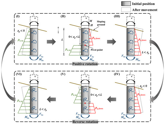
Shao et al. [26] proposed a series of soil-pile interaction models for rigid piles near slopes under combined - loading. In their framework, variations in the load ratio () lead to six distinct soil-pile interaction patterns, which are classified according to the location of the pivot point and the rotation direction of the pile. This interaction framework was systematically examined and validated in Shao et al. [26], and the identified interaction patterns were found to be consistent with the soil-pile failure mechanisms observed in numerical simulations. This agreement indicates that the six interaction modes can reasonably represent the progressive transition of the soil-pile system between different loading states and provide a physically based framework for constructing the - bearing capacity envelope.
Therefore, based on the above validated framework, the present study adopts the six interaction modes of Shao et al. [26] and extends their application from rigid piles near slopes to rigid piles installed directly on sandy slopes. Accordingly, Figure 2 illustrates the models adopted in the present study for deriving the bearing capacity envelope of a rigid pile on a sandy slope. The underlying assumptions are as follows:
Figure 2.
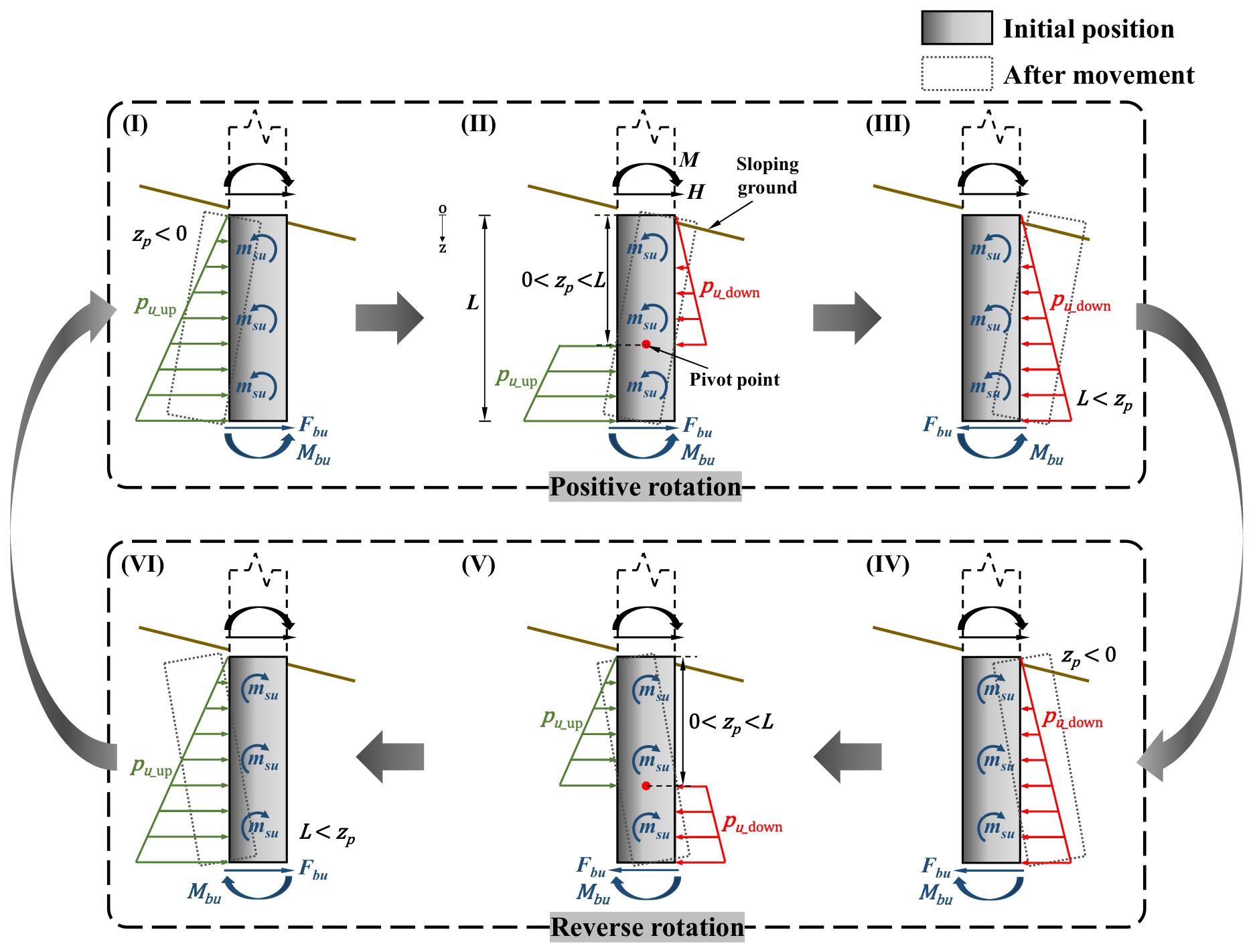
The soil-pile interaction models under varying pile-head loading ratio ().
- (a)
- The soil-pile system develops six interaction modes: (I) positive rotation (clockwise) with (where is the distance from the ground surface to the rotation point, positive downward); (II) positive rotation with ; (III) positive rotation with ; (IV) negative rotation (counter-clockwise) with ; (V) negative rotation with ; (VI) negative rotation with .
- (b)
- The interaction models incorporate four soil reaction components: the primary resistance, distributed lateral soil resistance [FL−1], and the additional resistances, namely base shear [F], base moment [FL], and distributed vertical shear-induced moment [F] (all evaluated at the limit state). These additional resistance components are introduced to account for the size effects (diameter and slenderness ratio effects) commonly observed in large-diameter piles, as their contributions generally become increasingly important with increasing pile diameter and decreasing ratio, particularly at (e.g., [28,29,30,31]).
- (c)
- The influence of the slope on the distributed lateral soil resistance is explicitly considered ( and correspond to uphill and downhill displacements of pile, respectively). In addition, the slope effect on the distributed vertical shear-induced moment is taken into account because is assumed to depend on the distributed lateral resistance , which varies with slope inclination angle and the pile displacement direction relative to the slope. This treatment differs from that of Shao et al. [26], in which the corresponding for clay was related to the undrained shear strength and therefore was not explicitly affected by the slope.
- (d)
- The influence of the slope on the base shear and base moment is neglected as an idealization. This assumption is motivated by the localized nature of the soil resistance mechanisms associated with the pile base: the mobilized soil zone contributing to and is concentrated within a relatively small region around the pile base and may therefore be less directly affected by the slope surface than the distributed shaft resistances. This localized base mechanism can also be observed in the numerical simulations of Shao et al. [26]. However, the independence of the base resistance components from slope inclination has not been quantitatively established for very short piles or for all pile-slope configurations. Accordingly, neglecting the slope effect on and should be regarded as a simplifying assumption rather than a universally validated condition. This treatment is consistent with the idealizations adopted in some previous studies of pile-slope interaction [32].
- (e)
- The present model considers combined horizontal force and moment loading but does not explicitly account for an externally applied vertical load or its interaction with the horizontal and moment capacities. Accordingly, all soil reaction components (, , , and ) are evaluated without accounting for any additional effects associated with an externally applied vertical load. The detailed formulations of these soil reaction components are presented in the following sections.
Notably, the foregoing assumptions implicitly imply that the relevant soil resistance components can simultaneously reach their limiting values at the ultimate state. This represents an idealized condition adopted to construct the equilibrium-based ultimate capacity envelope under extreme combinations of horizontal load and moment. In practice, however, the mobilization of individual resistance components depends on the loading path and history, and full simultaneous mobilization may rarely occur, which may introduce a certain discrepancy between the idealized model and actual conditions. Nevertheless, the resulting failure envelope provides a useful representation of the ultimate resistance domain of the soil-pile system for engineering assessment.
2.2. Derivation of Bearing Capacity Envelope
Based on the interaction patterns depicted in Figure 2, the horizontal load and the moment at the pile head (i.e., the ultimate pile-head load corresponding to the limit soil reactions) can be expressed by static equilibrium for each mode (owing to mathematical integration limits, the cases with or are adjusted to the boundary values or , respectively):
For mode I ()
for mode II ()
for mode III ()
for mode IV ()
for mode V ()
for mode VI ()
With these parametric expressions, the complete horizontal-moment capacity envelope can be readily obtained by varying over the interval :
As noted by Shao et al. [26], the failure envelope generated using this approach may contain small gaps near the endpoints of adjacent interaction-mode branches. The discontinuous branch results and the corresponding completed envelope have been illustrated in Figure 9a,b of Shao et al.’s paper [26]. These gaps arise from changes in the direction and mobilization of the additional resistance components between interaction modes, which lead to locally discontinuous transitions between the corresponding limiting states. Because these components generally make secondary contributions relative to the dominant lateral soil resistance , the resulting gaps are confined to small regions near the ends of the envelope branches. The endpoints of adjacent branches can therefore be connected by straight-line segments as a practical local interpolation between neighboring limiting states. This treatment completes the capacity envelope while having a limited effect on its overall shape and extent.
Nevertheless, this interpolation introduces some local approximation error near the ends of the envelope, and its magnitude may increase with increasing pile diameter and decreasing ratio, as the relative contributions of the additional resistance components become more significant. The acceptability of this approximation is supported by the results reported by Shao et al. [26], together with the further validation results presented in this study, which indicate that its influence remains localized and does not materially affect the overall envelope. One additional issue, however, is whether connecting adjacent branches in this way preserves the convexity of the resulting envelope. This aspect was not explicitly examined by Shao et al. [26] and is therefore further assessed using the validation cases presented later in this study.
2.3. Determination of Soil Reaction Components
With the framework defined by Equations (1)–(7) established, the remaining task is to determine each soil reaction component, which is elaborated below.
2.3.1. Lateral Soil Pressure Incorporating Slope Effect
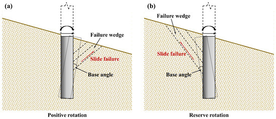
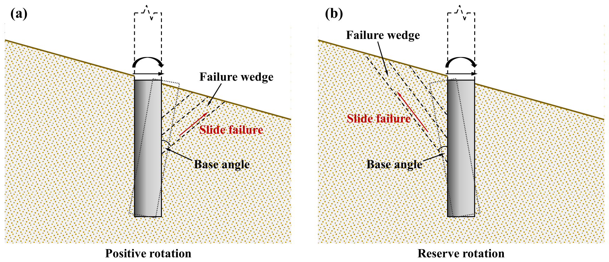
The distributed lateral soil pressure is the most dominant among all reaction components. The failure wedge model, originally proposed by Reese et al. [33], has been widely adopted to calculate the ultimate lateral soil resistance in shallow soils, owing to its ability to capture the wedge-type slide failure mechanism of a laterally loaded soil-pile system [34,35,36]. Moreover, this wedge failure mechanism has also been observed in field tests on piles near slopes [9,10]. Consequently, many researchers [3,13,27,32,37,38] have modified the failure wedge model to evaluate the ultimate lateral soil resistance, mostly for the case where the pile displaces towards the downhill direction. Among these, Shao et al. [13,38] introduced the concept of an optimal base angle for the failure wedge, which is determined by minimizing the soil resistance rather than assuming a fixed value of . This concept was later adopted and extended by Xia et al. [27] to the uphill displacement case. The wedge failure mechanisms for downhill and uphill pile displacements are schematically shown in Figure 3a and Figure 3b, respectively.
Figure 3.
Wedge failure mechanisms for (a) downhill and (b) uphill pile displacements.
Since the formulation proposed by Xia et al. [27] is the most recent among the available failure-wedge type models and provides a relatively rigorous derivation of the ultimate lateral soil resistance, the present study adopts their formulation as the basis for . The original formulation of Xia et al. [27] was developed primarily for pile movement in the uphill direction and considered a finite distance between the pile and the slope toe. In the present study, this boundary condition is modified by setting the horizontal distance between the pile and the slope toe to zero, corresponding to a pile installed directly on the slope. Based on the structure of the original formulation, it is further recognized that the model can be generalized to both uphill and downhill pile movements by reversing the sign of the slope angle, with and representing uphill and downhill movements, respectively. Thus, the same framework can be consistently applied to both directions without introducing a separate formulation. In addition, the active earth pressure behind the pile is neglected because its magnitude is relatively small compared with the passive resistance mobilized in front of the pile. Accordingly, the ultimate lateral soil resistance per unit length, , is summarized as follows:
for shallow soils (wedge-type failure):
for deep soils (flow-around failure):
where
In the above equations and denote the ultimate soil resistances for the shallow wedge-type failure and the deep flow-around failure, respectively; represents the total soil resistance mobilized by the wedge mechanism over a certain depth range below the ground surface. The auxiliary quantities , , , , , and are intermediate variables used in deriving the ultimate lateral soil resistance. As they are not independent model parameters, their detailed definitions and derivations are omitted here for conciseness and can be found in Xia et al. [27]. The key soil and geometrical parameters governing the resistance formulation are defined below.
Here, is the effective unit weight of the soil; is the effective internal friction angle; is the interface friction angle between the pile and soil, determined according to Table 1; is the active earth pressure coefficient; is the at-rest earth pressure coefficient; and is the slope angle (positive for uphill movement and negative for downhill movement, i.e., for and for ). The fan angle of the wedge, , is related to the relative density of sand; following Bowman [39], is typically taken as approximately – for loose sand and approaches for dense sand, while following Reese et al. [33], is typically taken as . The key parameter is the base angle of the wedge, , which is taken as the angle that minimizes at each depth (i.e., the optimal failure angle, which varies with depth). Xia et al. [27] did not explicitly specify the admissible range of the . Relevant discussions on the admissible range and the occurrence of singular values were provided by Shao et al. [38]. Following the same rationale, geometric constraints are imposed on the generalized formulation of the Xia et al. [27] model adopted herein to ensure geometric consistency of the failure wedge and to avoid singularities in the calculation. Accordingly, for uphill movement, the admissible range is , whereas for downhill movement, it is . Finally, is the equivalent depth correction for the deep failure mechanism, obtained by equating and setting ; further details are available in Xia et al. [27].
Table 1.
Recommended Values of [40].
2.3.2. Additional Resistances for Large-Diameter Piles
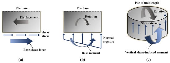
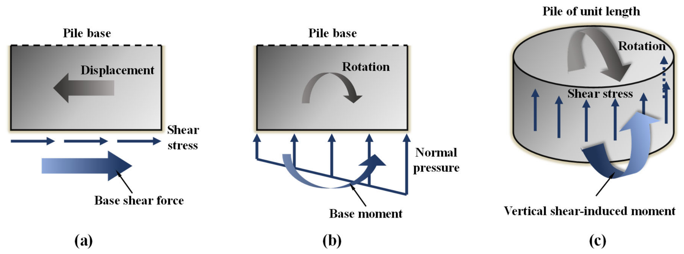
The additional resistances, beyond the distributed lateral soil pressure, constitute key sources of the size effects observed in large-diameter piles. Current mainstream research emphasizes three such components: base shear, base moment, and distributed vertical shear-induced moment. Their formation mechanisms are schematically illustrated in Figure 4. Drawing upon previous studies [41,42], Shao et al. [31] summarized simplified expressions for the ultimate limit state of these three additional resistances as follows:
Figure 4.
Formation mechanisms of the additional resistances: (a) base shear; (b) base moment; (c) distributed vertical shear-induced moment.
Among these, Equation (18) is derived from the theoretical solution of Bateman et al. [42] with certain simplifications; Equation (19) originates from the ultimate moment capacity formula for a surface circular footing proposed by Gottardi et al. [41], with the pile-base normal stress assumed to be equal to the vertical overburden pressure, consistent with the assumption that the effects of an externally applied vertical load are neglected; and Equation (20) is obtained by simply multiplying the unit shear resistance at the pile base by the base area, using the same assumption for the pile-base normal stress. In Equation (19), the bearing capacity factor can be taken as , according to Meyerhof [43], where is the passive earth pressure coefficient.
It should be noted that, in the present formulation, , , and are treated as distinct resistance components and combined additively to construct the idealized ultimate - resistance boundary, without explicitly considering their mutual coupling, pile-base separation, or loading-path-dependent redistribution of resistance. Accordingly, and represent the limiting base resistance components rather than detailed contact-dependent responses. Although arises from vertical shear stresses along the soil-pile interface and is physically distinct from the distributed lateral resistance, its magnitude is evaluated as a function of following Shao et al. [31]; thus, is quantitatively related to, but not an independent or duplicate of . For piles on sloping ground, this dependence is consistently reflected by evaluating piecewise from and over the corresponding pile segments in Modes II and V. The limiting values of these components are therefore used to define the idealized ultimate resistance boundary rather than to imply simultaneous mobilization during a specific loading path; detailed coupled soil-pile interaction and progressive contact evolution are beyond the scope of the present model and constitute potential directions for future research.
2.4. Calculation Procedure
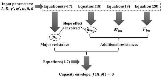
With the computational framework for the capacity envelope and all necessary soil reaction components established by Equations (1)–(20), the - capacity envelope can be readily generated by specifying the input parameters: , , , , , , and . The entire procedure (see Figure 5) is straightforward and computationally efficient, facilitating its practical application in engineering design.
Figure 5.
Calculation procedure of the proposed method.
3. Validation
This section aims to validate the theoretical method proposed in the preceding section for generating the - capacity envelope of large-diameter rigid piles in sandy soils. The adopted cases include the finite element limit analysis (FELA) conducted in this study and several available experimental and numerical results from the literature, providing validation under various parameter conditions.
3.1. Validation Against the FELA in This Study
Given the scarcity of existing experimental studies on this specific topic, i.e., rigid piles embedded in sandy slopes, and the fact that available tests are mostly confined to particular loading conditions without providing complete failure envelopes, it is necessary to resort to numerical simulations to generate complete failure envelopes for a thorough validation of the proposed method. Thus, numerical simulations are performed using the FELA software OPTUM-G3. Both level-ground and sloping-ground conditions are modeled to systematically investigate the bearing behavior of rigid piles.
3.1.1. Model Establishment and Verification
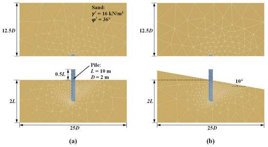
Two types of finite element models are established to represent the level-ground (Figure 6a) and sloping-ground conditions (, Figure 6b). Owing to symmetry, half-models are adopted to reduce computational cost. The geometric configuration of the models is illustrated in Figure 6. The pile has an embedded length of 10 m, a free length of 5 m above the ground surface, and a diameter of 2 m. The soil domain extends in the horizontal direction and in the vertical direction. The lateral boundaries of the soil are constrained against horizontal displacements, while the bottom boundary is fully fixed. The pile is modeled as a rigid body with a typical unit weight of 22 kN/m3. The soil behavior is described by the Mohr-Coulomb failure criterion, with typical sand parameters of kN/m3 and . The soil-pile interface is modeled as a shear joint with zero tensile strength. For each terrain condition, two interface friction angles, and , are considered to simulate perfectly smooth and perfectly rough contact conditions, respectively. Combined - loads with a wide range of ratios are applied at the pile head, followed by limit analyses performed using the software. The grid adaptive technique incorporated in OPTUM-G3 facilitates automated mesh generation and iterative refinements during the analysis process, ensuring reliable predictions while optimizing computational effort. The “mixed” element type is adopted, as it is capable of producing calculation results that closely bracket the upper and lower bounds. Three iterations of grid self-adaptation are performed, with the number of elements increasing from approximately 3000 to 10,000. Figure 6a,b present the adaptively refined meshes at the final iteration for two representative models.
Figure 6.
Finite element models for (a) level ground and (b) sloping ground (), showing model geometry and adaptively refined meshes.
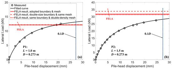
To validate the reliability of the aforementioned modeling approach, two additional finite element models are established, following the field tests reported by Wang et al. [44]. The soil parameters adopted are kN/m3 and . The pile dimensions and loading conditions are as follows: Pile P1 has a length of 1.0 m, a diameter of 0.273 m, and a loading eccentricity of 0.33 m; Pile P2 has a length of 1.5 m, a diameter of 0.273 m, and a loading eccentricity of 0.35 m. The soil-pile interface friction angle is taken as , consistent with the typical recommended value for steel piles. The computed ultimate lateral capacities from the FELA are compared with the measured results in Figure 7. Because the final loading displacement recorded for Pile P1 is relatively small, the scattered measured data are fitted using a hyperbolic curve to better represent the overall load-displacement trend over a larger displacement range.
Figure 7.
Comparison between predicted ultimate lateral capacities from FELA and measured load-displacement curves for two piles from the field tests of Wang et al. [44]: (a) Pile P1; (b) Pile P2.
In addition to the baseline boundary size and mesh density adopted above, two additional cases, including one with an enlarged boundary and the other with a refined mesh, are also considered to assess the sensitivity of the FELA results to these modeling parameters. For Pile P1, increasing either the boundary size or the mesh density produces negligible changes in the FELA results. Taking a displacement of as the criterion for determining the ultimate lateral capacity, the difference between the capacity obtained from the fitted curve of the measured data and that predicted by the baseline FELA model is approximately 10%. For Pile P2, mesh refinement again has a negligible effect, while increasing the boundary size results in a change of less than 10%. The ultimate capacity at a displacement of obtained from the fitted curve differs from the baseline FELA result by less than 15%.
Considering the inherent complexity and uncertainties associated with field tests, these differences indicate that the adopted modeling approach provides a reasonable prediction of the measured lateral capacities. The additional sensitivity analyses also show that the selected boundary size and mesh density have limited influence on the predicted ultimate lateral capacity for the two cases, supporting their use as a reasonable balance between computational efficiency and numerical accuracy.
3.1.2. Comparison with FELA Results
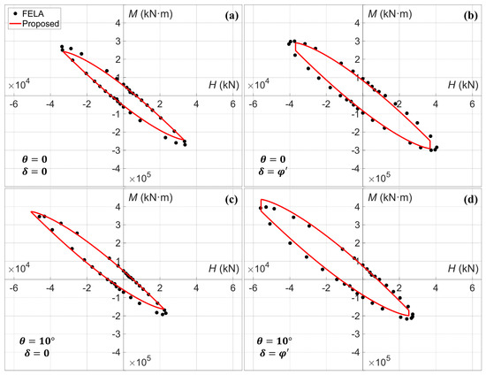
The - envelopes obtained from the FELA described in Section 3.1 (the moment taken at the ground surface rather than at the pile head) are compared in Figure 8 with the corresponding theoretical predictions derived from the proposed method. To ensure consistency with the theoretical formulation, the FELA moments, originally applied at the pile head, are converted to moments at the ground surface using (), where is the length of the pile above the ground surface. In the theoretical calculations, the fan angle of the wedge, , is taken as , within the range recommended by Bowman [39]. This choice also provides better agreement with the FELA results. Figure 8a–d present the results for four combinations of slope angle and interface friction condition, namely: Figure 8a , ; Figure 8b , ; Figure 8c , ; and Figure 8d , . Across all four cases, the theoretical predictions show generally good agreement with the FELA results in all quadrants. Relatively visible discrepancies are observed only near the two ends of the envelope in the second and fourth quadrants, but these deviations remain within acceptable limits.
Figure 8.
Comparison between the proposed theoretical envelopes and FELA results for different slope angles and interface friction conditions: (a) , ; (b) , ; (c) , ; and (d) , .
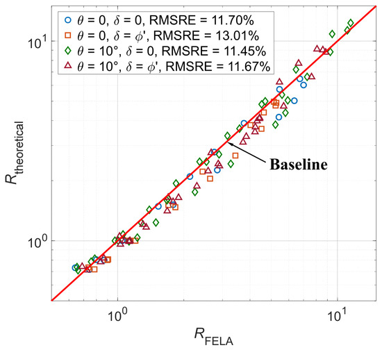
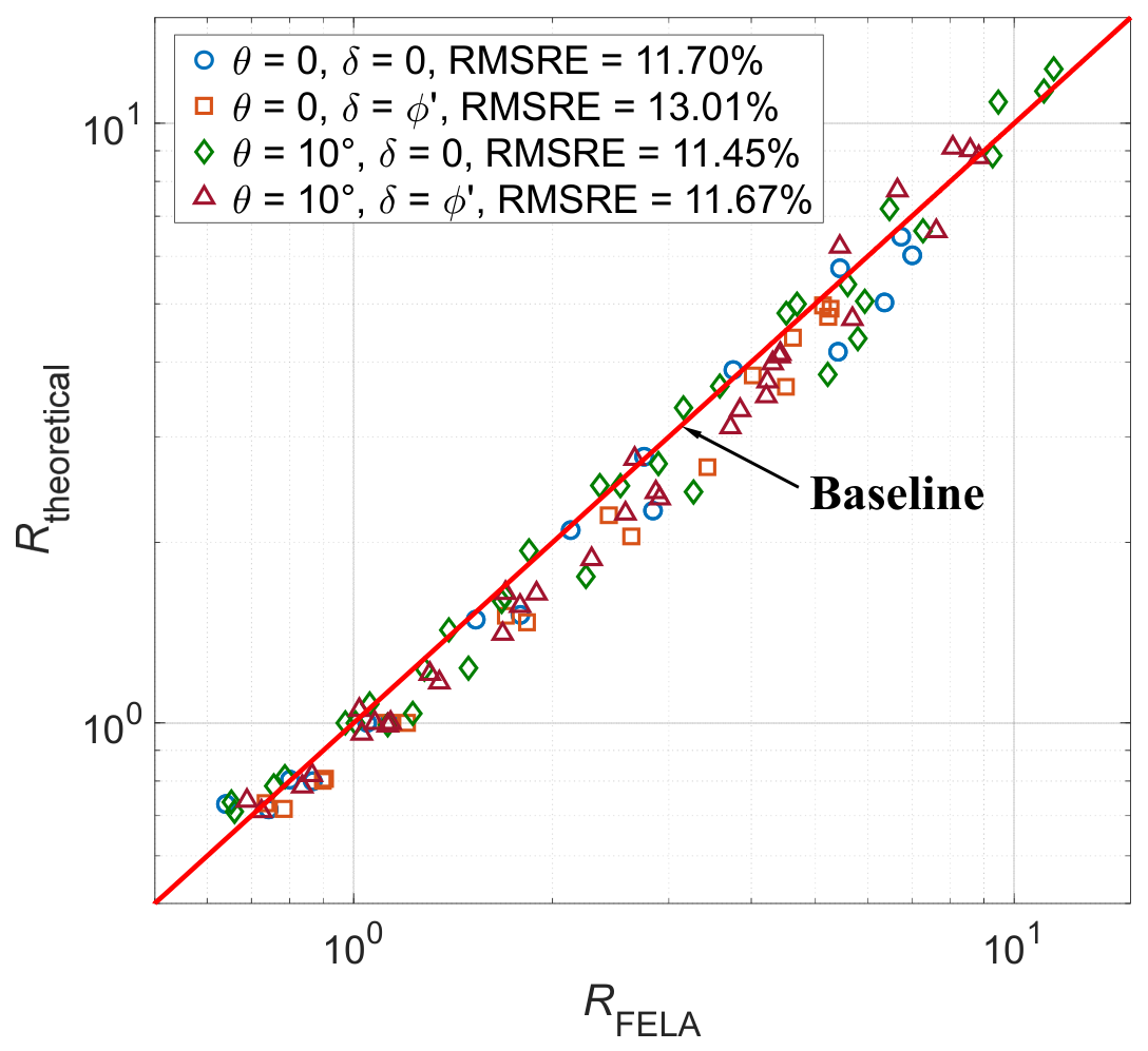
To further quantify the discrepancy between the two sets of results, the normalized envelope radius at a given ratio is defined as:
where and denote the theoretical ultimate capacities under pure horizontal force and pure bending moment in the positive loading direction, respectively, i.e., the intersections of the theoretical envelope with the positive -axis and the positive -axis. The FELA result is then denoted as , and the theoretical result as . Figure 9 compares and at different ratios for the above four combinations of slope angle and interface friction condition. All results lie closely along the perfect-prediction line, indicating overall agreement, consistent with the observation in Figure 8. Specifically, for and , the root-mean-square relative error (RMSRE) is 11.70% and the maximum positive relative error (corresponding to overestimation) is 14.32%; for and , the RMSRE is 13.01%, with all errors negative, indicating underestimation and no overestimation; for and , the RMSRE is 11.45% and the maximum positive relative error is 14.72%; and for and , the RMSRE is 11.67% and the maximum positive relative error is 16.12%.
Figure 9.
Quantitative comparison between the theoretical and FELA results for four combinations of slope angle and interface friction condition.
These comparisons indicate reasonable agreement, with RMSREs of 11.45–13.01% and a maximum overestimation of 16.12%; one case consistently underestimates. Given that relative errors within approximately 25% are commonly regarded as still providing meaningful guidance, such discrepancies are generally acceptable for preliminary assessment and comparative purposes, provided that an appropriate safety factor is applied. Nevertheless, the method should not replace rigorous analyses in final design, particularly near the envelope ends in the second and fourth quadrants. Overall, it effectively captures the main features of the - envelope under level and sloping ground, including interface friction effects, and can serve as a practical preliminary tool for estimating the - capacity of rigid piles in sand.
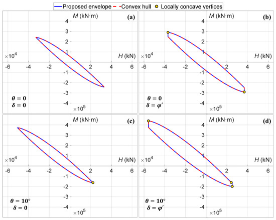
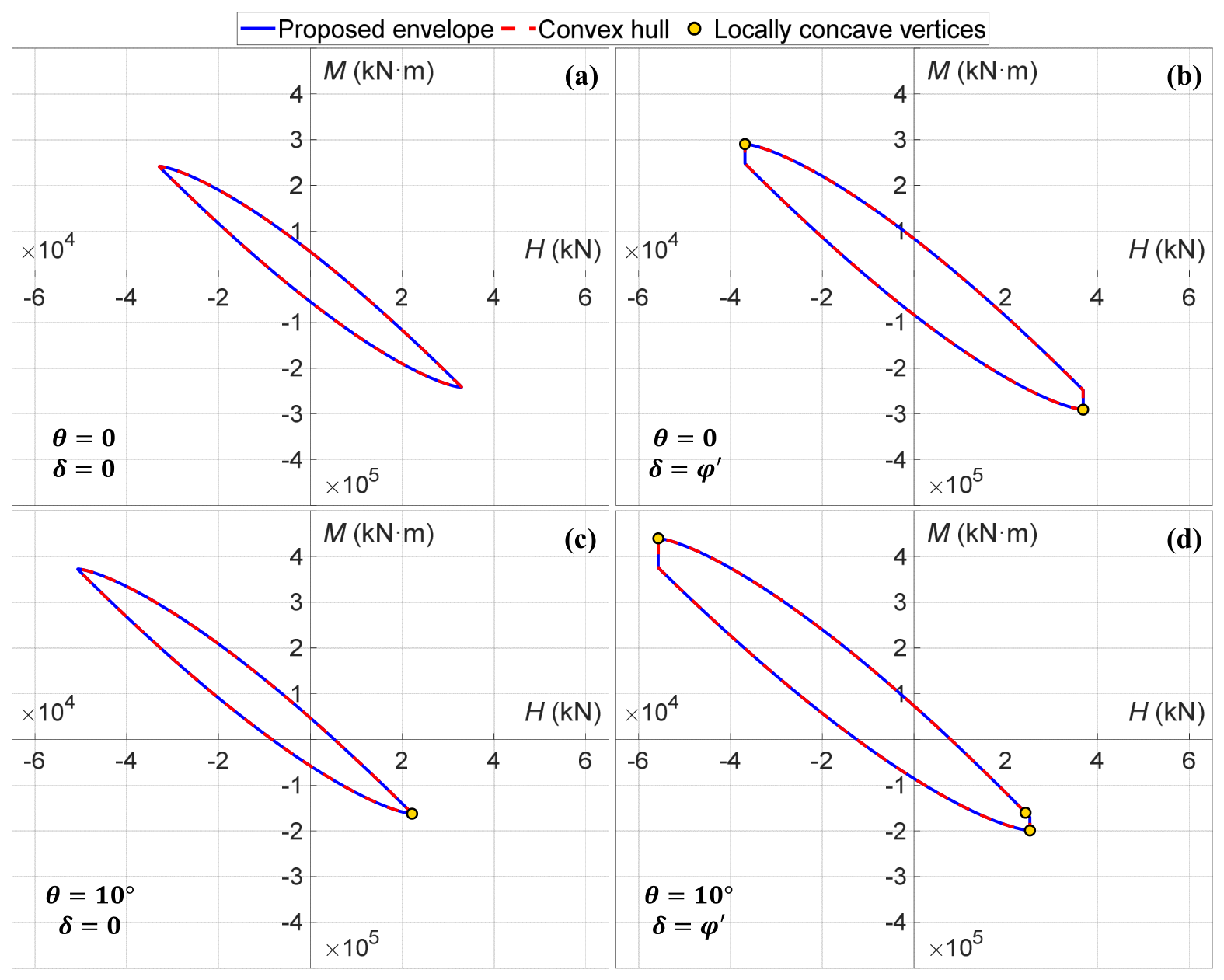
In addition to the comparisons with FELA results, the convexity of the failure envelopes is examined globally and locally for the four validation cases. As shown in Figure 10, the envelopes generated by the proposed method (blue solid lines) are visually indistinguishable from the convex hulls of the discrete points obtained directly from Equations (1)–(7) (red dashed lines), indicating that the straight-line connections between adjacent branches have a negligible effect on the overall envelope shape. The local convexity check identifies two locally concave vertices in Figure 10b, one in Figure 10c, and three in Figure 10d. However, their deviations from the corresponding convex hulls are negligible. These minor local departures from strict convexity may result not only from the interpolation procedure but also from numerical errors in determining the optimal failure-wedge base angle and equivalent depth for calculating . Although strict mathematical convexity is therefore not fully satisfied, these minor deviations do not affect the practical applicability of the proposed envelopes.
Figure 10.
Global and local convexity checks of the failure envelopes for the four validation cases.
3.2. Validation Against Several Available Experimental and Numerical Results
To further assess the proposed theoretical method over a wider range of conditions, several available experimental and numerical results for piles on level or sloping ground are considered. As noted earlier, these studies generally report results at a specific ratio rather than complete failure envelopes. Therefore, the comparison is made in terms of the ultimate lateral capacity reported in the literature and the corresponding value predicted by the proposed envelope at the same ratio. The selected cases include centrifuge tests on level ground reported by Maatouk et al. [45] and a numerical study on sloping ground reported by Ng et al. [46], the latter involving a semi-rigid rather than fully rigid pile. The relevant parameters and the comparison between the reported and predicted ultimate lateral capacities are summarized in Table 2.
Table 2.
Comparison of the ultimate lateral capacity from the literature and the proposed method.
As shown in Table 2, the proposed method provides generally reasonable predictions over the cases considered, with relative errors ranging from −11.20% to 24.21%. The relatively larger discrepancy in Case III may be partly associated with the uncertainties inherent in centrifuge testing and the corresponding interpretation of the ultimate lateral capacity. For Case IV, the close agreement between the predicted and reported values provides additional support for the applicability of the proposed formulation to sloping-ground conditions, although the reference case involves a semi-rigid pile.
Overall, these comparisons extend the validation beyond the FELA results presented above by incorporating both experimental and numerical data from different ground conditions and loading configurations. The generally reasonable agreement across these independent cases provides further evidence that the proposed method can capture the main trends in ultimate lateral resistance and offers a practical framework for estimating the lateral capacity of rigid piles under a range of conditions.
4. Parametric Study
Having been validated in the preceding section, the proposed method is now employed to conduct a parametric study investigating the effects of several key factors on the - capacity envelope. These factors include the determination of empirical parameters (fan angle and interface friction angle ), the incorporation of additional resistances (, , ), and the extent of slope effect (slope angle ). The baseline parameters are set as: m, m, kN/m3, , , , and .
4.1. Effects of Fan Angle and Interface Friction Angle
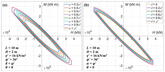
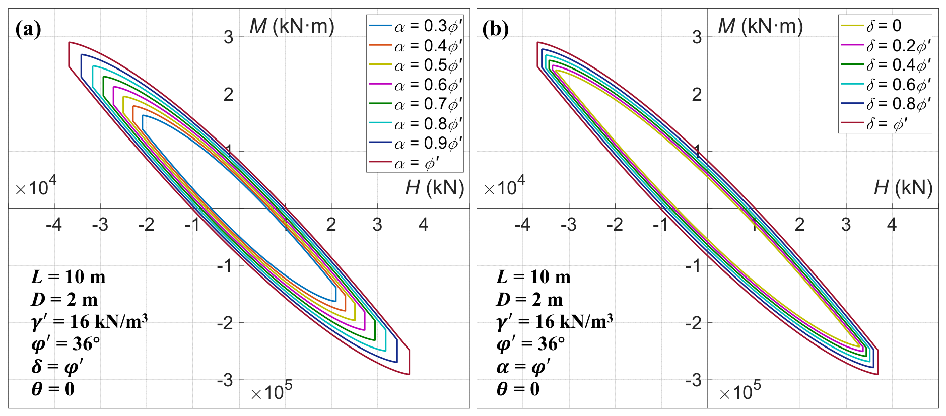
Figure 11a,b illustrate the influence of and on the - envelope, respectively. In Figure 11a, varies from to in increments of , while in Figure 11b, ranges from to in steps of . It is observed that an increase in either parameter leads to a full-range expansion of the envelope, with the enlargement being more pronounced near the two ends of the envelope in the second and fourth quadrants than in the intermediate regions.
Figure 11.
Effects of (a) fan angle and (b) interface friction angle on the - capacity envelope.
From the formulas given in Section 2, it is evident that a larger directly increases the lateral soil resistance , and consequently the distributed moment , which depends on . Similarly, an increase in enhances , , and simultaneously. However, a cross-comparison of the results in Figure 11 reveals that the envelope is considerably more sensitive to variations in than to changes in . This is likely because is more sensitive to the fan angle than to the interface friction angle .
Therefore, careful selection of is essential for obtaining accurate predictions of the full envelope in practice. Previous studies have predominantly focused on loading conditions in the first and third quadrants, where the influence of is relatively modest. However, when the complete envelope is considered, the effect of on the second and fourth quadrants—especially near the extremities—is by no means negligible. Current practice recommends that be taken within the range of to , with higher values corresponding to denser sands [13,37,39]. Nevertheless, this empirical guideline remains somewhat approximate, and further investigation into the rational determination of is warranted in future research.
4.2. Effects of Additional Resistances
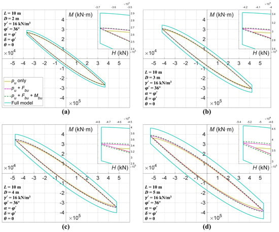
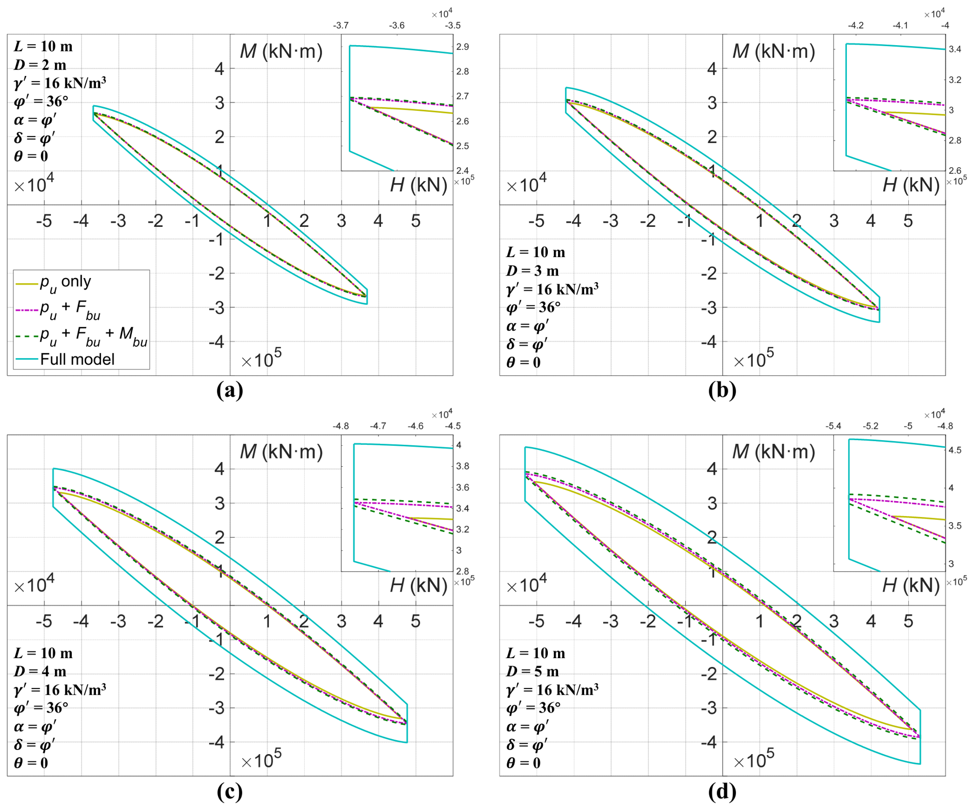
Figure 12a–d compare the - envelopes obtained under four progressively refined models: considering only the lateral soil resistance , adding the base shear , further including the base moment , and finally the full model incorporating all additional resistances (). The four subfigures correspond to pile diameters of = 2, 3, 4, and 5 m, respectively.
Figure 12.
Effects of additional resistances on the - capacity envelope for different pile diameters: (a) m, (b) m, (c) m, and (d) m.
It is evident that the inclusion of additional resistances expands the - envelope. Specifically, the incorporation of enlarges the envelope in both the - and -axis directions, whereas the inclusion of and only increases the extent of the envelope along the -axis. A cross-comparison of the subfigures further reveals that this expansion effect becomes more pronounced with increasing pile diameter and decreasing ratio. These observations are consistent with the findings reported by Shao et al. [26] for rigid piles in clay, as the theoretical framework of the present method is inherited from their work.
However, a difference exists in the relative contribution of each additional resistance component. As shown in Figure 12, exerts the most significant influence on the envelope, followed by , while plays a comparatively minor role (the effect remains negligible even for m.). This hierarchy differs from that observed for rigid piles near clay slopes by Shao et al. [26], possibly due to the combined effects of differences in soil properties and pile-slope configurations between the two studies.
4.3. Effects of Slope Inclination
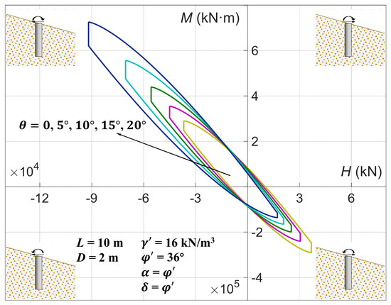
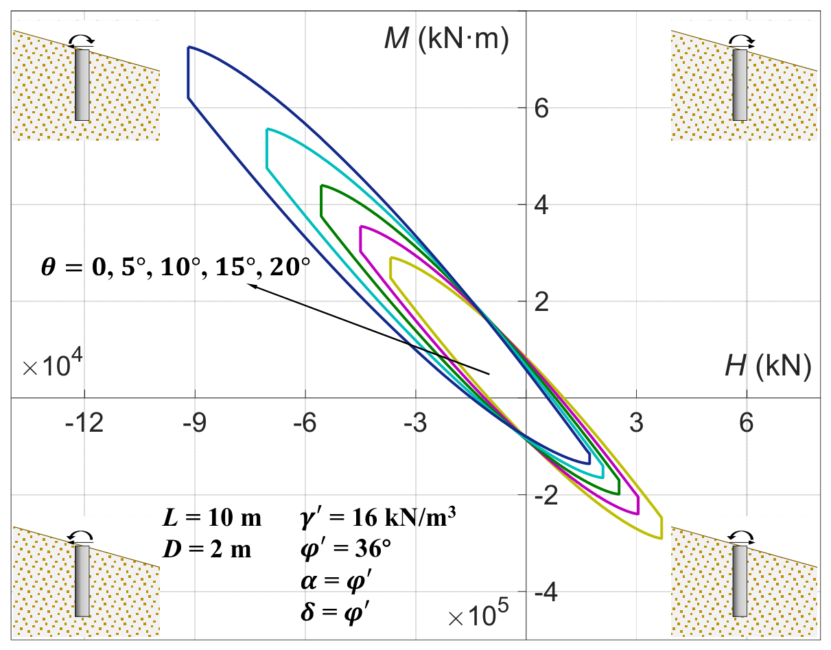
Figure 13 presents the - envelopes for various slope angles, ranging from to in increments of . Under level-ground conditions (), the envelope is symmetric about the origin, as expected, owing to the symmetric soil confinement on both sides of the pile. As the slope angle increases, this symmetry is progressively broken, resulting in a pronounced redistribution of the envelope in the - plane. Specifically, the extent of the envelope in the fourth quadrant decreases substantially, whereas that in the second quadrant expands considerably. In comparison, the first quadrant exhibits a slight reduction, while the third quadrant exhibits a minor expansion. Overall, the envelope progressively becomes skewed towards the second quadrant as the slope inclination increases.
Figure 13.
Effects of slope angle on the - capacity envelope.
Notably, the proposed method captures this slope-induced asymmetry directly through the underlying physical formulation and theoretical derivation, without introducing an empirical translation of the envelope. This is in contrast to the approach adopted by Bian et al. [24] and You et al. [25], in which the asymmetric envelope was represented through an empirical translation. The present formulation therefore provides a mechanically based description of the evolution of the - capacity envelope under sloping-ground conditions, rather than imposing the asymmetry through an additional empirical correction.
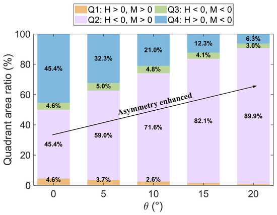
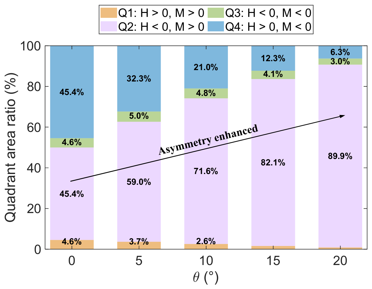
To further quantify the evolution of this slope-induced asymmetry, Figure 14 presents the ratios of the areas enclosed by the envelope in the four quadrants to the total envelope area as a function of slope angle. Under level-ground conditions, the area contributions of the first and third quadrants are equal at 4.6%, while those of the second and fourth quadrants are also equal at 45.4%, consistent with the central symmetry of the envelope. With increasing slope angle, the area contribution of the second quadrant increases markedly, whereas those of the first and fourth quadrants decrease monotonically. The area contribution of the third quadrant initially increases slightly and subsequently decreases as the slope angle becomes larger. These changes provide a quantitative representation of the progressive development of envelope asymmetry induced by the slope.
Figure 14.
Variation of the quadrant area ratios of the - capacity envelope with slope angle .
At , the area contribution of the second quadrant reaches 89.9%, whereas that of the fourth quadrant decreases to only 6.3%, indicating that the area enclosed in the second quadrant is more than ten times that in the fourth quadrant. This pronounced redistribution demonstrates that the slope effect can substantially alter not only the position and extent of the - envelope but also its overall distribution between different loading directions.
It should be noted, however, that the above results are predictions of the proposed theoretical model and have not yet been independently verified by experimental measurements. Therefore, the magnitude of the predicted asymmetry, particularly at relatively large slope angles, should be interpreted with appropriate caution and warrants further experimental investigation. Nevertheless, the results highlight the importance of explicitly accounting for slope-induced asymmetry when evaluating the combined horizontal and moment capacity of rigid piles in sand. The substantially stronger asymmetry predicted here, compared with the relatively modest asymmetry reported by Shao et al. [26] for rigid piles near clay slopes at a comparable slope angle of , also suggests that the influence of slope inclination may depend strongly on the mechanical characteristics of the surrounding soil. Further experimental and numerical studies are therefore needed to determine whether the stronger sensitivity predicted for sandy soils is representative of the actual response and to clarify the underlying mechanisms governing the difference between sand and clay.
5. Summary
This paper presents a theoretical method for determining the - bearing capacity envelope of large-diameter rigid piles embedded in sandy slopes. The main conclusions can be summarized as follows:
- •
- A theoretical formulation is developed by integrating the failure wedge model of Xia et al. [27] and the six-mode soil-pile interaction framework of Shao et al. [26]. It enables the generation of complete - envelopes for large-diameter rigid piles on sandy slopes.
- •
- The proposed method is validated against FELA results and independent experimental and numerical data. The four representative FELA cases give RMSREs of 11.45–13.01% and the maximum positive relative discrepancy of 16.12%, while the additional validation cases give relative errors of −11.20–24.21%. The comparisons indicate that the proposed formulation can reasonably reproduce the overall - capacity characteristics under the investigated conditions.
- •
- Parametric analyses show that, for the parameter ranges and reference conditions considered in this study, the fan angle has a more pronounced influence on the predicted envelope than the interface friction angle . Increasing the slope angle progressively increases the asymmetry of the - envelope, with the resistance becoming increasingly concentrated in the Q2 region; in the investigated case, Q2 and Q4 account for 89.9% and 6.3% of the total envelope area, respectively. The effects of pile diameter and ratio are also reflected through the increasing contributions of the additional resistance components.
- •
- The predicted - envelope can be used as an ultimate resistance boundary for preliminary design of rigid piles subjected to combined lateral force and overturning moment. For a given project, the envelope can be constructed using the characteristic soil, pile, and interface parameters, and the design load combination can then be compared with the predicted envelope after applying the relevant code-based resistance or partial factors. Serviceability requirements, such as lateral displacement and rotation, should be assessed separately [47].
Despite these contributions, several limitations of the present method should be acknowledged. The formulation adopts a simplified drained frictional-soil model and does not explicitly consider stress-dependent stiffness, evolving dilatancy, particle crushing, post-peak degradation [48], groundwater and partial-saturation effects, or detailed pile-soil contact evolution. The additional resistance components are treated as limiting contributions without explicitly modeling their mutual coupling and loading-path-dependent redistribution. Moreover, the validation covers a limited range of pile geometries, soil conditions, and slope angles, and the fan angle is selected based on published recommendations rather than an independently calibrated relationship. Future studies should therefore combine systematic physical tests and high-fidelity numerical analyses to examine a broader range of soil states, pile geometries, interface conditions, slope angles, and groundwater conditions, and to establish a more general procedure for selecting and describing the coupled resistance mechanisms.
Author Contributions
Conceptualization, P.G.; Methodology, P.G.; Software, Z.Z.; Validation, Z.Z. and J.Z.; Formal analysis, W.S.; Investigation, W.S.; Resources, J.Z.; Data curation, L.Z.; Writing—original draft, P.G.; Writing—review and editing, J.Z. and X.L.; Visualization, Z.Y.; Supervision, X.L.; Funding acquisition, X.L. All authors have read and agreed to the published version of the manuscript.
Funding
This research is supported by the National Natural Science Foundation of China (52274106) and the Natural Science Foundation of Guangdong Province, China (2026A1515010933).
Data Availability Statement
All data are available from the corresponding author upon reasonable request.
Conflicts of Interest
Author Zhongwei Zhou was employed by Hubei Shenlong Geological Engineering Investigation Institute Co., Ltd. The remaining authors declare that the research was conducted in the absence of any commercial or financial relationships that could be construed as a potential conflict of interest.
References
- Poulos, H.G.; Hull, T.S. The role of analytical geomechanics in foundation engineering. In Foundation Engineering: Current Principles and Practices; ASCE: Reston, VA, USA, 1989; pp. 1578–1606. [Google Scholar]
- Bhushan, K.; Fong, P.T.; Haley, S.C. Lateral load tests on drilled piers in stiff clays. J. Geotech. Eng. Div. 1979, 105, 969–985. [Google Scholar] [CrossRef] [Scilit]
- Gabr, M.A.; Borden, R.H. Lateral Analysis of Piers Constructed on Slopes. J. Geotech. Eng. 1990, 116, 1831–1850. [Google Scholar] [CrossRef] [Scilit]
- Mezazigh, S.; Levacher, D. Laterally Loaded Piles in Sand: Slope Effect on P-Y Reaction Curves. Can. Geotech. J. 1998, 35, 433–441. [Google Scholar] [CrossRef] [Scilit]
- Georgiadis, K.; Georgiadis, M. Undrained Lateral Pile Response in Sloping Ground. J. Geotech. Geoenviron. Eng. 2010, 136, 1489–1500. [Google Scholar] [CrossRef] [Scilit]
- Georgiadis, K.; Georgiadis, M. Development of p-y curves for undrained response of piles near slopes. Comput. Geotech. 2012, 40, 53–61. [Google Scholar] [CrossRef] [Scilit]
- Muthukkumaran, K. Effect of Slope and Loading Direction on Laterally Loaded Piles in Cohesionless Soil. Int. J. Geomech. 2014, 14, 1–7. [Google Scholar] [CrossRef] [Scilit]
- Deendayal, R.; Muthukkumaran, K.; Sitharam, T.G. Effect of Slope on p-y Curves for Laterally Loaded Piles in Soft Clay. Int. J. Geotech. Eng. 2018, 14, 1–15. [Google Scholar]
- Mirzoyan, A.D. Lateral Resistance of Piles at the Crest of Slopes in Sand. Master’s Thesis, Brigham Young University, Provo, UT, USA, 2007. [Google Scholar]
- Barker, P.D. Effects of Soil Slope on the Lateral Capacity of Piles in Cohesionless Soils. Master’s Thesis, Oregon State University, Corvallis, OR, USA, 2012. [Google Scholar]
- Nimityongskul, N.; Kawamata, Y.; Rayamajhi, D.; Ashford, S.A. Full-Scale Tests on Effects of Slope on Lateral Capacity of Piles Installed in Cohesive Soils. J. Geotech. Geoenviron. Eng. 2018, 144, 04017103. [Google Scholar] [CrossRef] [Scilit]
- Sawant, V.A.; Shukla, S.K. Effect of Edge Distance from the Slope Crest on the Response of a Laterally Loaded Pile in Sloping Ground. Geotech. Geol. Eng. 2014, 32, 197–204. [Google Scholar] [CrossRef] [Scilit]
- Shao, X.; Jiang, C.; Fu, Y.; Cao, R. A Modified Failure Wedge Model for Modeling Soil-Pile Interaction of Laterally Loaded Piles in Sand Considering Slope Effect. Int. J. Geomech. 2024, 24, 04024111. [Google Scholar] [CrossRef] [Scilit]
- Jala, Y.; Sawant, V.A.; Mishra, A. Development of p-y curves from numerical study of long piles in sandy slope. Ocean Eng. 2025, 319, 120275. [Google Scholar] [CrossRef] [Scilit]
- Butterfield, R.; Gottardi, G. A complete three-dimensional failure envelope for shallow footings on sand. Géotechnique 1994, 44, 181–184. [Google Scholar] [CrossRef] [Scilit]
- Ukritchon, B.; Whittle, A.J.; Sloan, S.W. Undrained limit analyses for combined loading of strip footings on clay. J. Geotech. Geoenviron. Eng. 1998, 124, 265–276. [Google Scholar] [CrossRef] [Scilit]
- Gourvenec, S.; Randolph, M.F. Effect of strength non-homogeneity on the shape of failure envelopes for combined loading of strip and circular foundations on clay. Géotechnique 2003, 53, 575–586. [Google Scholar] [CrossRef]
- Zafeirakos, A.; Gerolymos, N. Towards a seismic capacity design of caisson foundations supporting bridge piers. Soil Dyn. Earthq. Eng. 2014, 67, 179–197. [Google Scholar] [CrossRef] [Scilit]
- Graine, N.; Hjiaj, M.; Krabbenhoft, K. 3D failure envelope of a rigid pile embedded in a cohesive soil using finite element limit analysis. Int. J. Numer. Anal. Methods Geomech. 2021, 45, 265–290. [Google Scholar] [CrossRef] [Scilit]
- Chiou, J.S.; Chien, H.Y. Analytical interaction diagram for lateral responses of a rigid pile in homogeneous overconsolidated clay. J. Geotech. Geoenviron. Eng. 2021, 147, 05021008. [Google Scholar] [CrossRef] [Scilit]
- Chiou, J.S.; Chien, H.Y. Theoretical interaction diagrams of a laterally loaded rigid caisson considering base shear and moment resistances. Ocean Eng. 2022, 261, 111937. [Google Scholar] [CrossRef] [Scilit]
- Shao, X.; Jiang, C.; Fu, Y.; Yao, J.; Pang, L. Failure envelope for offshore rigid piles under combined horizontal-moment loading in clay with linearly increasing undrained shear strength. Ocean Eng. 2024, 307, 118168. [Google Scholar] [CrossRef] [Scilit]
- Sirimontree, S.; Panomchaivath, S.; Jitchaijaroen, W.; Banyong, R.; Keawsawasvong, S.; Jamsawang, P. An ANN based model for constructing undrained failure envelopes for circular piles under general loading. Ships Offshore Struct. 2025, 21, 1394–1416. [Google Scholar] [CrossRef] [Scilit]
- Bian, M.; Peng, J.; Zhang, X.; Li, J.; Qin, S. Bearing capacities of single piles under combined HM loading near slopes. Front. Mater. 2023, 10, 1180345. [Google Scholar] [CrossRef] [Scilit]
- You, X.Y.; Qian, S.Y.; Li, B.; Wang, J.; Xu, L.Y. Envelope and intelligent prediction of horizontal bearing capacity for offshore wind monopiles in sandy seabed under HM combined loading. Front. Earth Sci. 2025, 12, 1522279. [Google Scholar] [CrossRef] [Scilit]
- Shao, X.; Gao, X.; Yang, X.; Xu, M.; El Naggar, M.H.; Wu, W. H-M failure envelope for large-diameter rigid monopiles near sloping seabed in clay: Numerical investigation and theoretical methodology. Ocean Eng. 2025, 335, 121722. [Google Scholar] [CrossRef] [Scilit]
- Xia, L.; Gong, W.; Dai, G.; Chen, K.; Xie, H.; Peng, B.; Xu, J.; Li, W. A Method for Calculating Uphill Direction Lateral Response of Flexible Monopiles near the Slope Toe in Sand. Int. J. Geomech. 2026, 26, 04026039. [Google Scholar] [CrossRef] [Scilit]
- Burd, H.J.; Taborda, D.M.G.; Zdravković, L.; Abadie, C.N.; Byrne, B.W.; Houlsby, G.T.; Gavin, K.; Igoe, D.J.P.; Jardine, R.; Martin, C.; et al. PISA design model for monopiles for offshore wind turbines: Application to a marine sand. Géotechnique 2020, 70, 1048–1066. [Google Scholar] [CrossRef] [Scilit]
- Byrne, B.W.; Houlsby, G.T.; Burd, H.J.; Gavin, K.G.; Igoe, D.J.P.; Jardine, R.J.; Martin, C.M.; McAdam, R.A.; Potts, D.M.; Taborda, D.M.G.; et al. PISA design model for monopiles for offshore wind turbines: Application to a stiff glacial clay till. Géotechnique 2020, 70, 1030–1047. [Google Scholar] [CrossRef] [Scilit]
- Shao, X.; Fu, Y.; Jiang, C. Lateral soil-pile interaction of large-diameter rigid monopiles supporting OWTs in clay: Insights and an enhanced theoretical model. Appl. Ocean Res. 2024, 150, 104093. [Google Scholar] [CrossRef] [Scilit]
- Shao, X.; Wang, B.; Liu, L.; Huang, D.; Liu, H.; Liu, X.; El Naggar, M.H.; Wu, W. A unified hybrid beam model and transfer matrix solution for three novel OWT monopile foundations. Ocean Eng. 2026, 365, 127426. [Google Scholar] [CrossRef] [Scilit]
- Lin, M.; Jiang, C.; Liu, P.; Pang, L. Analysis of laterally loaded offshore pile near slope in sand considering slope height. Ocean Eng. 2022, 287, 112436. [Google Scholar] [CrossRef] [Scilit]
- Reese, L.C.; Cox, W.R.; Koop, F.D. Analysis of Laterally Loaded Piles in Sand. In Proceedings of the 6th Offshore Technology Conference, Houston, TX, USA, 5–7 May 1974; Volume 2, pp. 473–483. [Google Scholar]
- Kim, Y.; Jeong, S.; Lee, S. Wedge Failure Analysis of Soil Resistance on Laterally Loaded Piles in Clay. J. Geotech. Geoenviron. Eng. 2011, 137, 678–694. [Google Scholar] [CrossRef] [Scilit]
- Hajialilue-Bonab, M.; Sojoudi, Y.; Puppala, A.J. Study of Strain Wedge Parameters for Laterally Loaded Piles. Int. J. Geomech. 2013, 13, 143–152. [Google Scholar] [CrossRef] [Scilit]
- Shao, X.; Xu, M.; Mei, G.; El Naggar, M.H.; Wu, W. Development of a p-multiplier for laterally loaded single batter piles in sand based on simple upper bound analysis. Comput. Geotech. 2025, 184, 107268. [Google Scholar] [CrossRef] [Scilit]
- Chen, L.; Jiang, C.; Pang, L.; Liu, P. Lateral soil resistance of rigid pile in cohesionless soil on slope. Comput. Geotech. 2021, 135, 104163. [Google Scholar] [CrossRef] [Scilit]
- Shao, X.; Jiang, C.; Cao, R.; Pang, L.; Chen, L. Analysis for laterally loaded pile behavior on offshore sand slope crest considering friction effect and variational base angle in FW. Ocean Eng. 2022, 266, 112978. [Google Scholar] [CrossRef] [Scilit]
- Bowman, E.R. Investigation of the Lateral Resistance to Movement of a Plate in Cohesionless Soil. Master’s Thesis, University of Texas, Austin, TX, USA, 1958. [Google Scholar]
- Reese, L.C.; Isenhower, W.M.; Wang, S.T. Analysis and Design of Shallow and Deep Foundations; John Wiley & Sons: Hoboken, NJ, USA, 2006. [Google Scholar]
- Gottardi, G.; Houlsby, G.T.; Butterfield, R. Plastic response of circular footings on sand under general planar loading. Géotechnique 1999, 49, 453–469. [Google Scholar] [CrossRef] [Scilit]
- Bateman, A.H.; Crispin, J.J.; Mylonakis, G.E. Analytical nonlinear m-θ curves for monopiles in clay. J. Geotech. Geoenviron. Eng. 2025, 151, 04025024. [Google Scholar] [CrossRef] [Scilit]
- Meyerhof, G.G. Some recent research on the bearing capacity of foundations. Can. Geotech. J. 1963, 1, 16–26. [Google Scholar] [CrossRef] [Scilit]
- Wang, H.; Lehane, B.M.; Bransby, M.F.; Wang, L.Z.; Hong, Y. Field and numerical study of the lateral response of rigid piles in sand. Acta Geotech. 2022, 17, 5573–5584. [Google Scholar] [CrossRef] [Scilit]
- Maatouk, S.; Blanc, M.; Thorel, L. Effect of embedding depth on the monotonic lateral response of monopiles in sand: Centrifuge and numerical modelling. Géotechnique 2022, 74, 1111–1126. [Google Scholar]
- Ng, C.W.W.; Zhang, L.M. Three-dimensional analysis of performance of laterally loaded sleeved piles in sloping ground. J. Geotech. Geoenviron. Eng. 2001, 127, 499–509. [Google Scholar] [CrossRef] [Scilit]
- Zhanabayeva, A.; Sagidullina, N.; Kim, J.; Satyanaga, A.; Lee, D.; Moon, S.W. Comparative analysis of Kazakhstani and European design specifications: Raft foundation, pile foundation, and piled raft foundation. Appl. Sci. 2021, 11, 3099. [Google Scholar] [CrossRef] [Scilit]
- Peng, Y.; Yin, Z.Y.; Ding, X. Analysis of particle corner-breakage effect on pile penetration in coral sand: Model tests and DEM simulations. Can. Geotech. J. 2023, 60, 749–765. [Google Scholar] [CrossRef] [Scilit]

Disclaimer/Publisher’s Note: The statements, opinions and data contained in all publications are solely those of the individual author(s) and contributor(s) and not of MDPI and/or the editor(s). MDPI and/or the editor(s) disclaim responsibility for any injury to people or property resulting from any ideas, methods, instructions or products referred to in the content. |
© 2026 by the authors. Licensee MDPI, Basel, Switzerland. This article is an open access article distributed under the terms and conditions of the Creative Commons Attribution (CC BY) license.