


Abstract
To investigate the influence of polyoxymethylene (POM) fibers as a substitute for steel fibers (SF) on the flexural performance of ultra-high-performance concrete (UHPC) T-beams, material property tests and four-point bending tests on structural members were conducted. A theoretical formula for calculating the ultimate flexural capacity was derived based on cross-section internal force equilibrium analysis. Material test results indicate that the compressive strength of POM-UHPC is approximately 20% lower than that of SF-UHPC. POM-UHPC presents strain-softening characteristics under uniaxial tension with an initial cracking strength of 3.48 MPa, and its stress decays rapidly after cracking. In contrast, SF-UHPC exhibits distinct strain-hardening behavior, with an ultimate tensile strength of 7.81 MPa. Member test results demonstrate that the flexural capacity of both series of T-beams increases with the longitudinal reinforcement ratio. Under the same reinforcement condition, the bearing capacity of SF-UHPC beams is 8.3–11.1% higher than that of POM-UHPC beams. Crack pattern observations show that POM-UHPC beams develop fine, uniform, network-distributed cracks with excellent crack dispersion and deformation capacity, whereas SF-UHPC beams generate fewer cracks with larger main-crack widths. Based on the plane-section assumption and force equilibrium, calculation formulas for ultimate flexural capacity of both POM-UHPC and SF-UHPC T-beams are derived, in which a fiber type influence coefficient is introduced. Good agreement is achieved between calculated and experimental results. Although POM fibers reduce the compressive strength of UHPC and the bearing capacity of beam members, they significantly improve crack-control performance and structural toughness. POM-UHPC possesses obvious advantages in corrosion resistance and lightweight performance, and shows prospective advantages for potential corrosive-environment applications, while relevant durability tests remain to be further investigated. The strength loss can be compensated via reasonable structural design. The proposed modification coefficients are calibrated for the investigated parameter range, and further validation is needed for extended engineering conditions.
1. Introduction
Ultra-high-performance concrete (UHPC) is a state-of-the-art cement-based composite characterized by ultra-high compressive strength, excellent durability and outstanding fracture toughness [1]. With compressive strength typically exceeding 120 MPa [2,3], UHPC has been widely applied in long-span bridges, high-rise buildings and special engineering structures, bringing revolutionary advances to modern civil engineering design [4]. The incorporation of steel fibers (SF) is a core technical approach to achieve high flexural toughness and crack resistance of UHPC, which enables UHPC to bear complex tensile and bending loads in structural members.
However, conventional steel fibers in UHPC face inherent limitations in practical engineering: high self-weight increases structural dead load, susceptibility to corrosion in chloride-rich environments impairs long-term durability, and fiber agglomeration degrades construction workability [5,6,7,8,9]. In particular, in marine or saline–alkali environments, corrosion of steel fibers can cause spalling of concrete cover and deterioration of structural performance, which significantly shortens the service life of UHPC components and increases maintenance costs. To address these drawbacks, high-performance organic fibers with corrosion resistance and low density have become a research hotspot for replacing steel fibers in UHPC.
Polyoxymethylene (POM) fiber, as a new type of high-performance synthetic fiber, features high tensile strength, excellent alkali corrosion resistance, low density and good dispersion in cement matrix [10]. Previous studies have verified the reinforcing effect of POM fibers on UHPC at the material scale. Cheng et al. [11] reported that UHPC with 2% volume fraction of POM fibers achieved a compressive strength of 123 MPa and a flexural strength of 18.6 MPa, with good fiber–matrix interfacial bonding to restrict crack propagation. Wang et al. [12] conducted four-point bending tests on material specimens and observed obvious deflection-hardening behavior, enhanced flexural toughness and stable post-cracking bearing capacity of POM fiber-reinforced UHPC. Ban et al. [13] found that POM fibers greatly improved the impact resistance of UHPC, and the impact toughness increased by 170% at a fiber content of 2.5%. Xia et al. [14] investigated the effects of POM macro-fiber length and dosage on workability and fracture toughness, and obtained a compressive strength of 113.2 MPa and a fracture toughness of 1.67 MPa·m^0.5 with 12 mm fibers at 1.5% dosage. In addition, Deng et al. [15] revealed the synergistic toughening effect of hybrid steel–POM fibers, with impact ductility 2.06–2.29 times that of single steel fiber reinforcement, and better ductility in the post-peak stage of load–deflection curves.
While material-level investigations of POM-UHPC have been gradually enriched, research on UHPC structural members has been mostly focused on steel fiber-reinforced systems. Extensive experimental and theoretical studies have been carried out on steel fiber-reinforced UHPC beams, T-beams and bridge girders, systematically revealing their flexural bearing capacity, crack evolution law and failure modes under bending loads [16,17,18]. These studies have formed a relatively mature research framework for steel fiber-reinforced UHPC flexural members, but the conclusions cannot be directly applied to organic fiber-reinforced UHPC structures due to the significant differences in fiber modulus, tensile behavior and interface bonding characteristics.
In response to the corrosion problem of steel fibers, other corrosion-resistant polymer fibers such as polyvinyl alcohol (PVA) and recycled plastic fibers have also been explored to partially replace steel fibers in UHPC. Existing material-scale studies show that organic fiber incorporation generally reduces the peak compressive and tensile strength of UHPC, but brings the advantages of improved crack dispersion, lower self-weight and better long-term durability potential in aggressive environments [19,20]. However, most of these studies remain at the material specimen level, and systematic structural beam tests on UHPC fully reinforced with organic fiber are still very limited.
Nevertheless, existing studies on POM-UHPC mainly focus on basic mechanical properties at the material scale, including compression, flexure and impact resistance [21,22,23,24,25]. Research on the mechanical response of POM-UHPC at the structural member scale is still very limited. T-shaped cross-sections are widely adopted in bridge superstructures and prefabricated components, where members sustain combined flexural-shear actions under real service conditions. Up to now, few experimental programs have been carried out to characterize the cracking load, ultimate flexural resistance, crack evolution pattern and failure modes of POM-UHPC T-beams. Moreover, available flexural capacity calculation models are mostly calibrated for steel fiber-reinforced UHPC beams, and there are few dedicated theoretical formulas that consider the strain-softening tensile feature induced by full POM fiber replacement. This knowledge gap greatly hinders practical engineering adoption of POM-UHPC in corrosive-environment structures.
Against this background, this paper conducts four-point bending tests on POM-UHPC T-beams and makes a systematic comparison with steel fiber-reinforced UHPC (SF-UHPC) counterparts. The effects of fiber type and longitudinal reinforcement ratio on bearing capacity, deflection response and crack distribution characteristics are analyzed. Based on the plane-section assumption and stress block equivalence principle, a theoretical calculation formula for the ultimate flexural capacity of UHPC T-beams is established, with a fiber type influence coefficient introduced. This study is expected to provide theoretical reference and design support for the engineering application of POM fibers in UHPC structures, especially for lightweight and high-durability structures in corrosive environments.
2. Material Tests
2.1. Raw Materials and Mix Proportions
The UHPC matrix used in this study consists of tap water, P·O 42.5 Portland cement, fly ash, silica fume, refined quartz sand, and a KST-UHPC polycarboxylate superplasticizer. Table 1 summarizes the physical features and strength parameters of Portland cement. Fly ash and silica fume act as supplementary cementitious materials for optimizing particle packing density and filling internal voids; their physical indices are listed in Table 2. Quartz sand possessing over 96% SiO2 content and well-graded particles serves as rigid skeleton material for improving matrix compactness and volume stability. The polycarboxylate superplasticizer selected in this test provides a water-reducing ratio higher than 32%.
Table 1.
Physical properties and strength of cement. Standard values are according to GB 175-2007 [26].
Table 2.
Physical properties of supplementary cementitious materials.
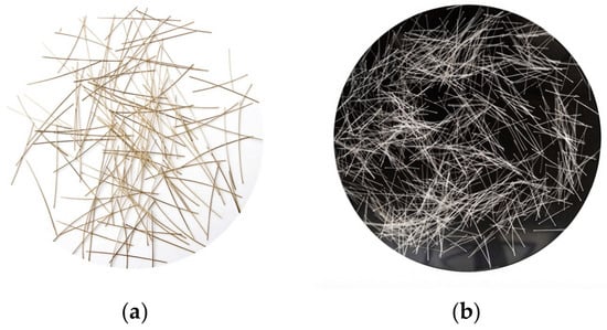
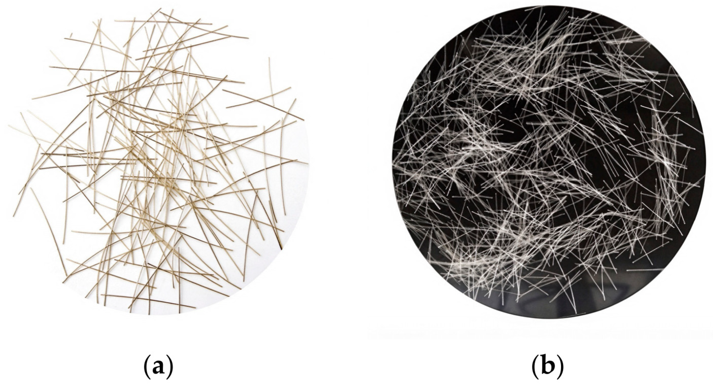
Copper-plated micro steel fiber and POM fiber were chosen as reinforcing fillers with identical 2% volume dosage. Geometric parameters and mechanical properties of these fibers are presented in Table 3. Distinct material characteristics generate different toughening and crack-bridging behaviors for comparative experimental analysis. The macroscopic morphology of copper-plated micro steel fiber and POM fiber used in the test is shown in Figure 1.
Table 3.
Physical and mechanical properties of fibers.
Figure 1.
Morphology of reinforcing fibers: (a) copper-plated micro steel fiber; (b) POM fiber.
A constant water to binder ratio of 0.17 was adopted, and detailed mix proportions of UHPC are summarized in Table 4. All raw materials were mixed inside a 60 L horizontal forced mixer following predefined feeding sequences until homogeneous mixtures without fiber agglomeration were obtained. Specimens were cast right after mixing procedures finished.
Table 4.
Mix proportions of UHPC (kg/m3).
2.2. Mechanical Property Tests
2.2.1. Compressive Test
The 100 mm × 100 mm × 100 mm cube specimens and 100 mm × 100 mm × 300 mm prism specimens were prepared together with T-beam components and subjected to the same curing regime. Compressive test outcomes are listed in Table 5. SF-UHPC yields an average cubic compressive strength of 127.9 MPa and a prismatic axial compressive strength of 101.6 MPa, whereas POM-UHPC achieves 99.6 MPa and 81.6 MPa for the corresponding indices.
Table 5.
Comparison of compressive mechanical performance.
Substitution of steel fiber by POM fiber brings about a 22.1% drop in cubic compressive strength and a 19.7% reduction in axial compressive strength. High-modulus steel fibers exert a strong confinement effect on the matrix, restricting both elastic and plastic deformation. By contrast, POM fiber has a considerably lower elastic modulus and offers weak compressive confinement, which contributes little to compressive strength improvement.
2.2.2. Uniaxial Tension Test
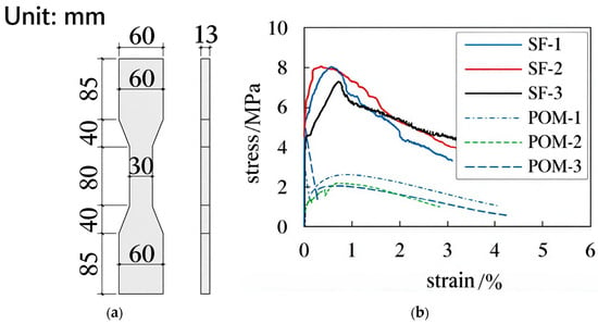
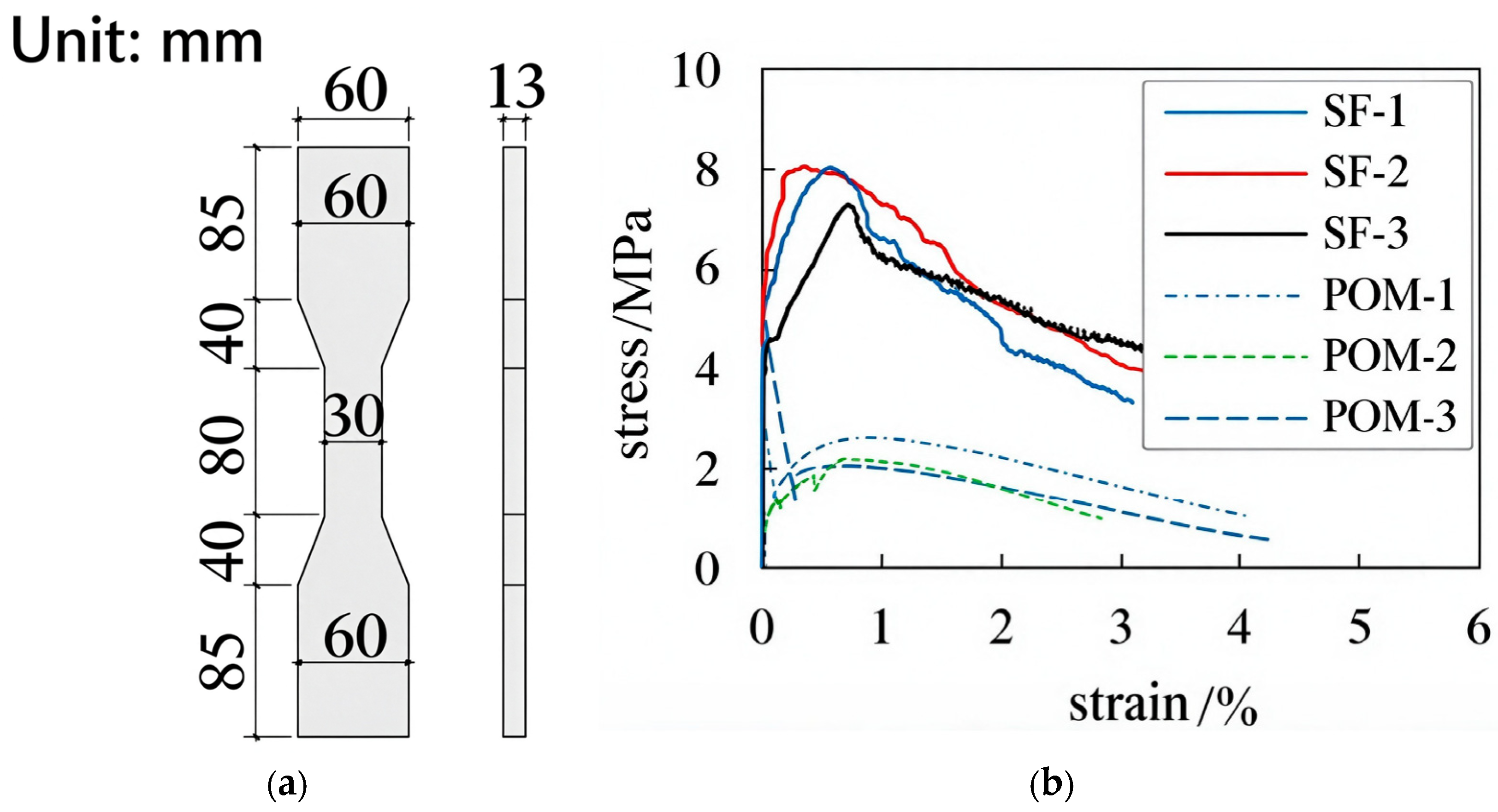
Direct uniaxial tension measurements were carried out to assess tensile properties of the material. The geometric dimension of tensile samples is presented in Figure 2a. Three parallel specimens were manufactured for each fiber group. The displacement controlled loading mode was applied at a velocity of 0.2 mm/min, and the resulting stress–strain responses are given in Figure 2b. The plotted curves are the complete responses of three individual replicate specimens rather than averaged curves.
Figure 2.
Uniaxial tension test: (a) geometry of tensile specimen (unit: mm); (b) tensile stress–strain curves of three individual replicate specimens for SF-UHPC and POM-UHPC groups.
SF-UHPC delivers favorable tensile properties, with an average initial cracking strength of 5.26 MPa and an ultimate tensile strength of 7.81 MPa at the ultimate tensile strain of 0.68%. Tensile stress will not fall off drastically after matrix cracking, reflecting representative strain-hardening characteristics and high toughness. On the other hand, POM-UHPC shows an initial cracking strength of 3.48 MPa, yet stress declines rapidly upon crack initiation. Once cracks emerge, the fiber–matrix interface loses bonding capacity quickly. POM fibers break prematurely and fail to maintain steady crack-bridging stress, hence producing inferior toughness.
3. Specimen Tests
3.1. Specimen Design
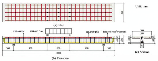
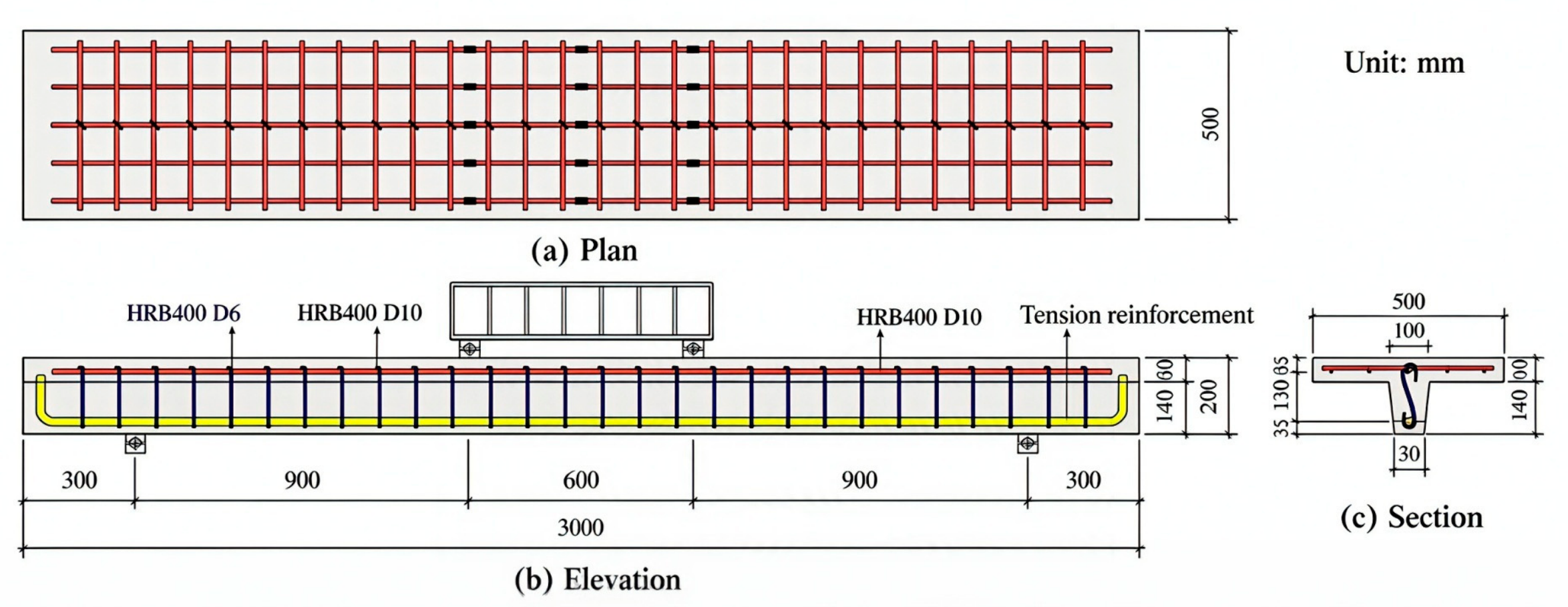
Four UHPC T-beam specimens reinforced with steel fibers (SF) and POM fibers were fabricated with varying longitudinal reinforcement ratios for subsequent four-point bending tests. Table 6 lists the core parameters of these test specimens. Among them, two specimens belong to the SF-UHPC group and another two belong to the POM-UHPC group, aiming to investigate how fiber category and longitudinal reinforcement ratio influence mechanical behaviors. An HRB400 D10 steel mesh at 100 mm spacing was embedded within the flange of every T-beam sample. HRB400 D6 stirrups were placed at 100 mm intervals to provide sufficient shear resistance and avoid premature local damage. Primary experimental variables cover the fiber type (SF/POM) and longitudinal tensile reinforcement ratio of the web. The geometric sizes and reinforcement configurations of the specimens are illustrated in Figure 3. Formworks were stripped 24 h after casting. All test beams and accompanying material samples were cured in standard environment for 28 d to achieve complete strength gain.
Table 6.
Summary of beam specimens.
Figure 3.
Specimen dimensions and reinforcement arrangement.
Considering the high cost of UHPC structural specimens and laboratory resource constraints, four T-beam specimens were designed in this study, covering two typical longitudinal reinforcement ratios (1.08% and 2.04%) widely used for UHPC bridge T-beams. Multiple replicate samples were prepared for compressive and uniaxial tensile material tests to ensure the reliability of matrix mechanical properties. Although replicate beam specimens were not manufactured for each group, consistent trends in bearing capacity, crack distribution and load–deflection responses can be identified when comparing POM-UHPC and SF-UHPC series, which can reflect the essential influence mechanism of fiber type on flexural performance. Further tests with more specimens and broader parameter ranges will be carried out in follow-up research.
3.2. Loading and Measurement Scheme
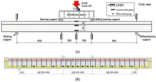
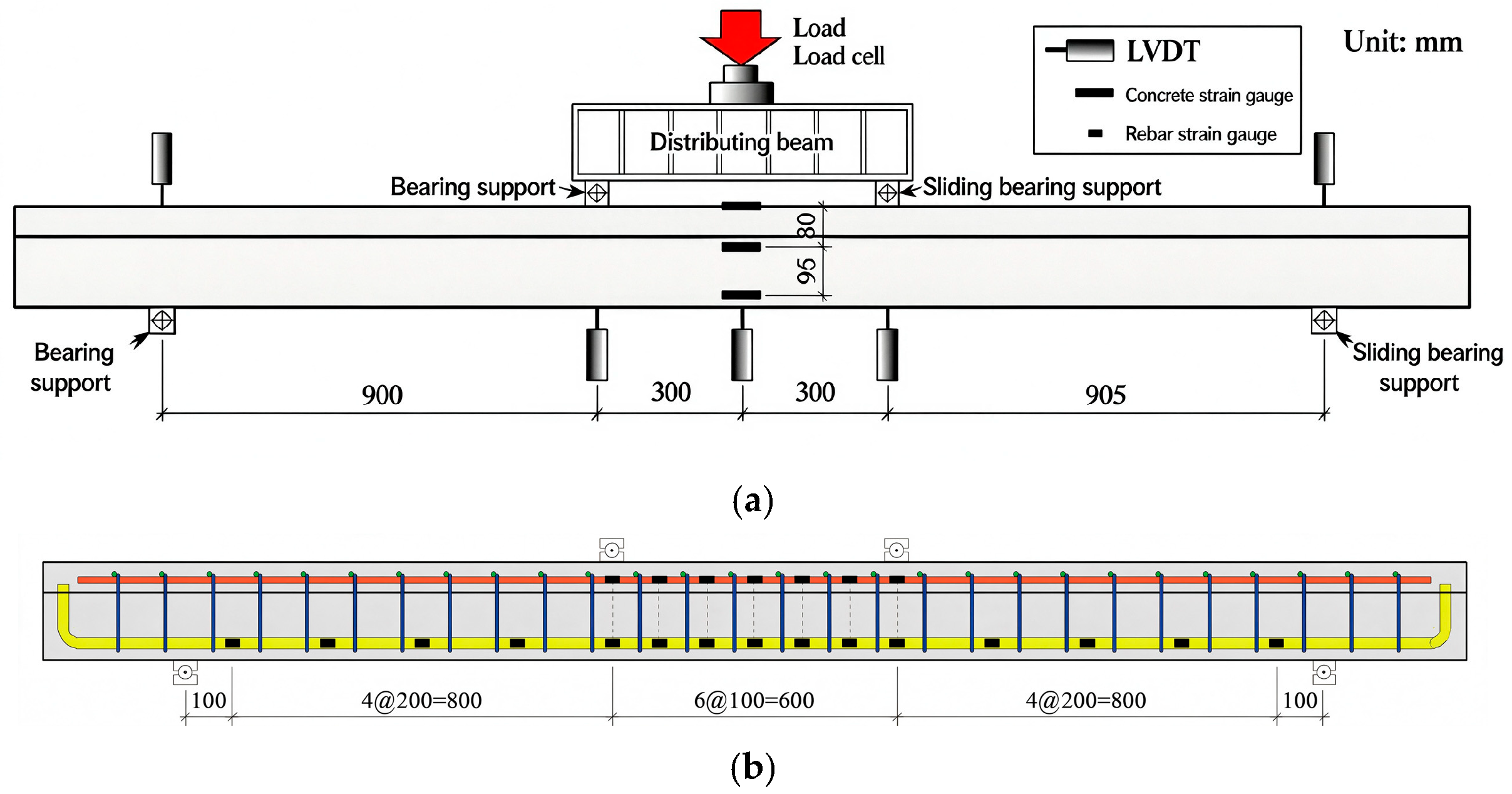
The loading and measurement setup for all T-beams is shown in Figure 4. Symmetric two-point loading is adopted, creating a 600 mm long pure-bending segment at mid-span. Beams and distributing beams are supported as simply supported members. Load is applied by a 500 kN electro-hydraulic servo actuator, and real-time load data are collected by a load sensor mounted on top of the distributing beam.
Figure 4.
Loading and measurement arrangement: (a) loading setup (unit: mm); (b) layout of steel-strain gauges (Elevation).
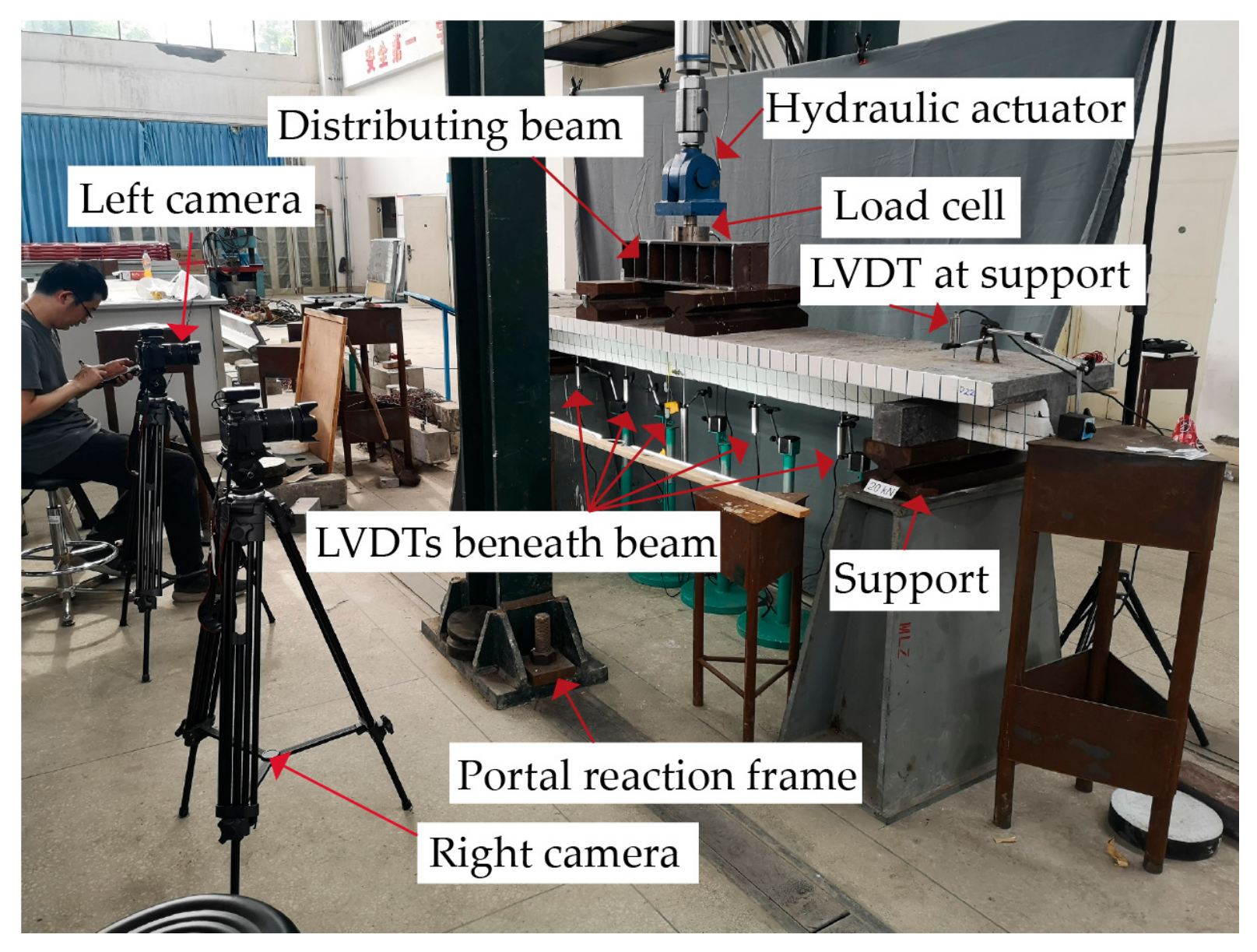
Multiple linear variable differential transformers (LVDTs) were set at the loading points, mid-span and supports to measure vertical displacement responses. Photos of the on-site test setup are given in Figure 5. Monotonic load-controlled loading is applied at 0.2 kN/s. Loading was continuously applied until visible crushing failure was observed on the top compression flange (ultimate failure state). Manual unloading was implemented after ultimate failure occurrence to protect test equipment and facilitate post-test crack pattern documentation.
Figure 5.
On-site test photograph.
4. Test Results
4.1. Crack Pattern and Failure Mode
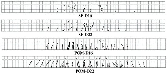
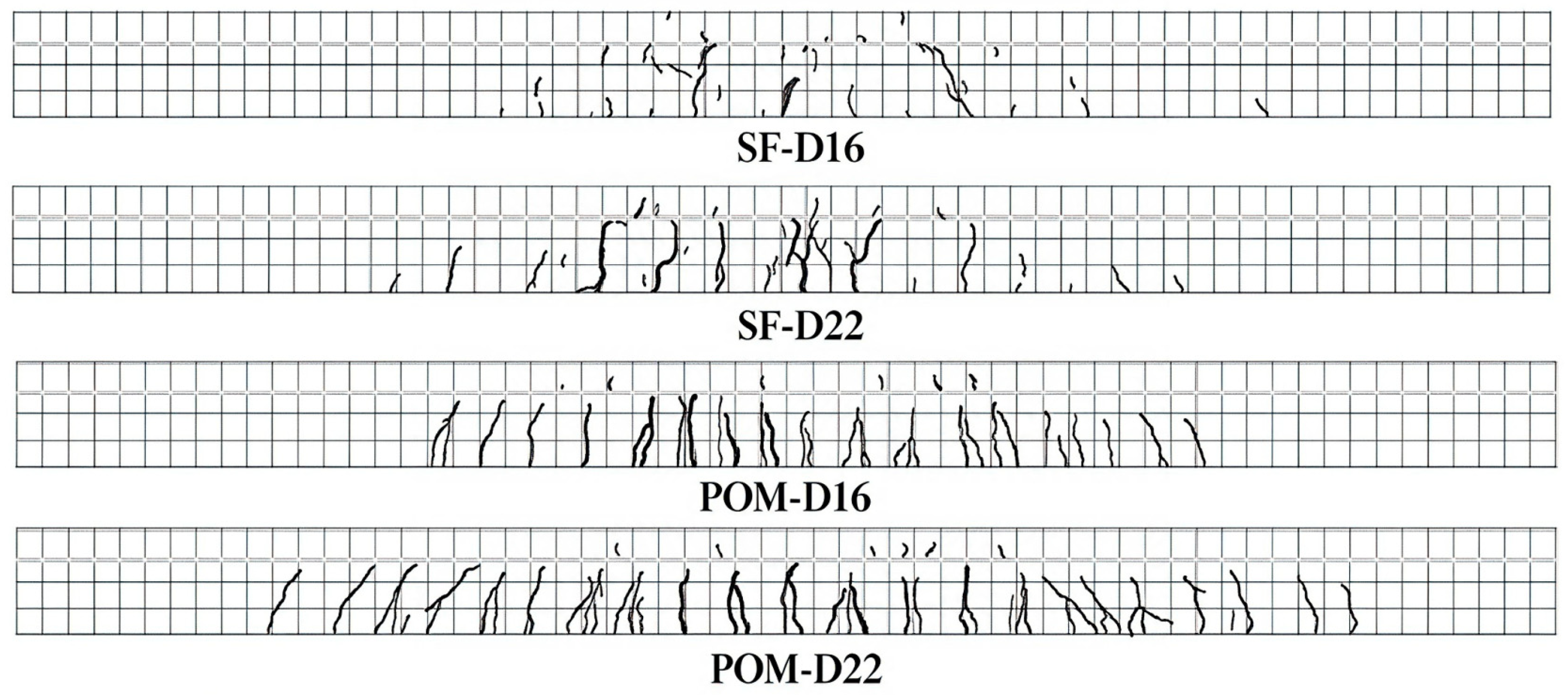
To better observe the crack pattern, the grid with size of 5 cm × 5 cm drawn on the side surface of specimens. Crack distributions of all specimens after loading are shown in Figure 6. In the early loading stage, load increases linearly and beams remain elastic. Vertical cracks initiate near mid-span as load rises. With further loading, cracks multiply within the pure-bending zone and crack width expands, propagating toward the top flange. A hissing sound caused by steel fiber pull-out can be heard for SF-UHPC beams. Final failure occurs when horizontal crushing cracks emerge in the top flange.
Figure 6.
Crack distribution patterns of tested T-beam specimens.
For SF-UHPC specimens, cracks are relatively sparse, dominated by a small number of long, wide primary cracks. For POM-UHPC T-beams, crack quantity increases significantly; numerous fine, short micro-cracks and secondary cracks interweave into a reticular cracking pattern. In terms of failure characteristics, SF-UHPC failure concentrates on several major cracks with relatively brittle performance and limited energy dissipation capacity. By contrast, the abundant multi-crack system of POM-UHPC redistributes internal stress and dissipates substantial energy before ultimate failure, reflecting prominent ductility and toughness.
In this study, the ultimate load of each specimen is defined as the peak load recorded right before the crushing of top flange UHPC.
4.2. Load–Mid-Span Deflection Curves
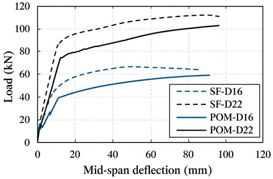
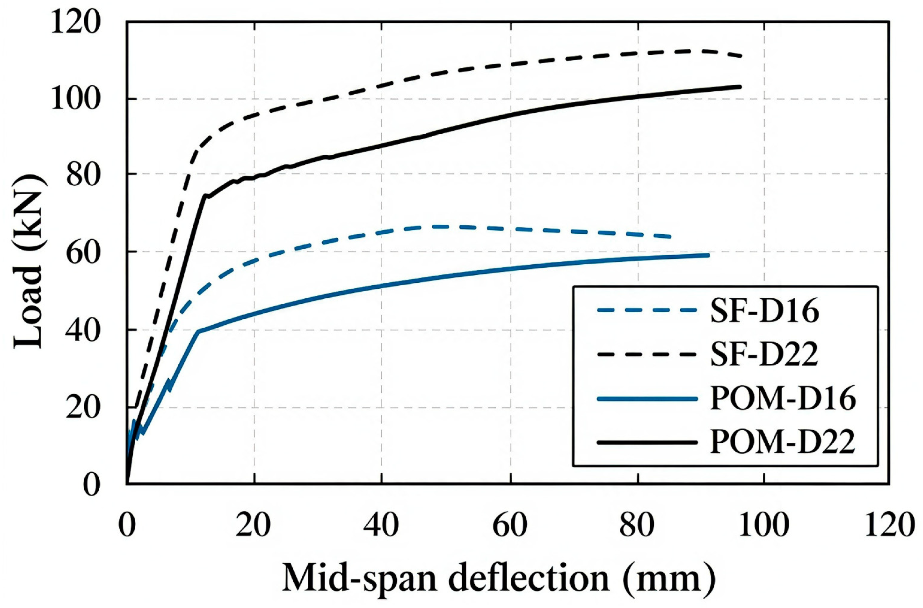
Load–mid-span deflection curves for all specimens are plotted in Figure 7. The flexural bearing capacity of T-beams rises with increasing longitudinal reinforcement ratio. For beams reinforced with D16 bars, the ultimate capacity of SF-D16 reaches 66.7 kN while POM-D16 reaches 59.3 kN; the capacity of the SF-UHPC beam is 11.1% higher. For D22-reinforced specimens, SF-D22 achieves 112.6 kN and POM-D22 achieves 103.3 kN, with an 8.3% capacity difference. This discrepancy arises from the inherent mechanical differences between the two materials. Benefitting from high tensile strength and strain-hardening behavior, SF-UHPC provides sustained crack-bridging stress after tension-zone cracking and acts as secondary reinforcement, improving post-crack sectional tensile resistance and ultimate moment capacity. Owing to strain-softening tensile behavior and low initial cracking strength, POM-UHPC loses its reinforcing effect after cracking. The neutral axis shifts upward, and sectional bending resistance mainly relies on longitudinal steel bars, leading to lower ultimate bearing capacity.
Figure 7.
Load–mid-span deflection curves of tested beams.
Despite lower bearing capacity, POM-UHPC T-beams exhibit distinctive load–deflection characteristics. Favorable fiber dispersibility promotes dense micro-crack networks, differing substantially from SF-UHPC failure patterns. SF-UHPC is suitable for main load-bearing components requiring high ultimate capacity. POM-UHPC demonstrates advantages in corrosion resistance and lightweight performance. Its reduction in bearing capacity can be compensated for through rational structural design, making it promising for structures in corrosive environments or with strict self-weight limits.
To quantitatively compare the deformation performance between SF-UHPC and POM-UHPC T-beams, key deformation-related indices, including yield deflection , ultimate deflection , and displacement ductility coefficient , are calculated and listed in Table 7. Under the same reinforcement ratio, POM-UHPC specimens show larger yield deflection and ultimate deflection than SF-UHPC counterparts. The displacement ductility coefficients of POM-UHPC beams are comparable to those of SF-UHPC beams. This quantitatively demonstrates the superior deformability of POM-UHPC beams, which originates from its dense multi-crack network.
Table 7.
Quantitative deformation indices of tested T-beam specimens.
4.3. Longitudinal Reinforcement Stress Distribution of POM-UHPC Specimens
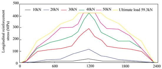
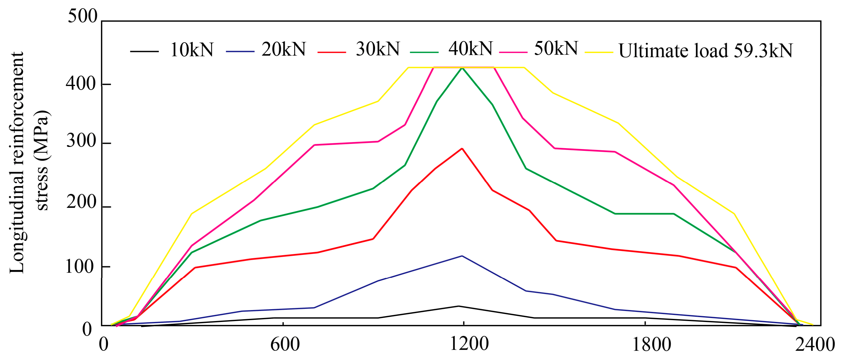
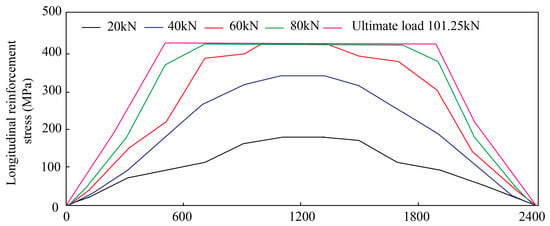
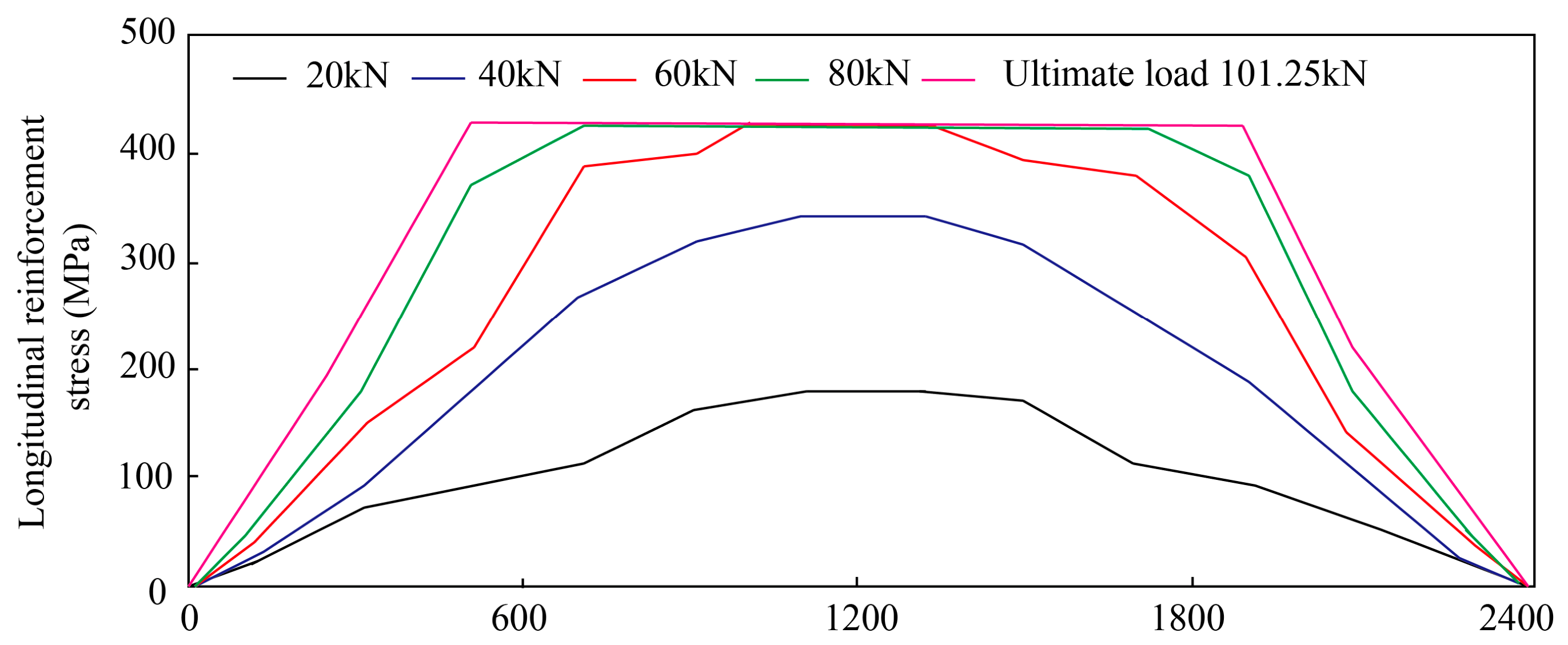
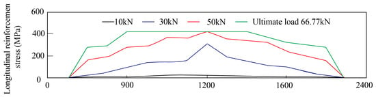
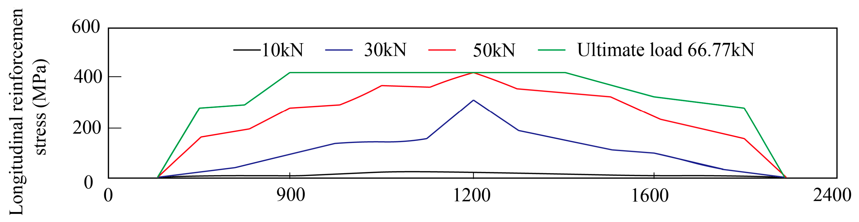
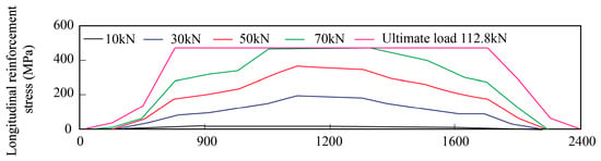
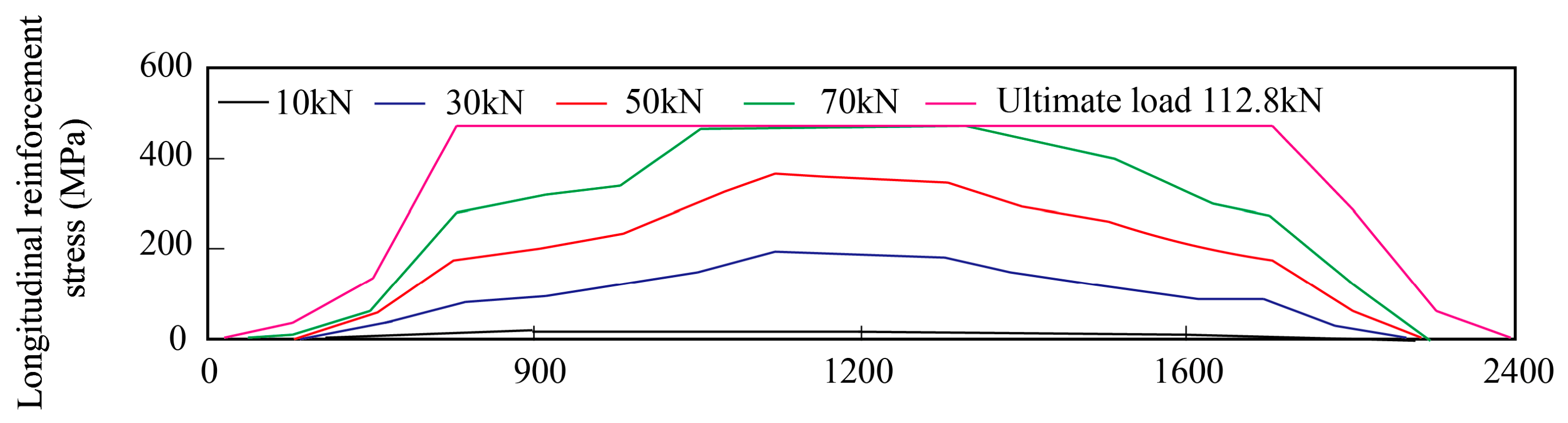
Based on strain measurements of web longitudinal bars, the stress evolution of longitudinal reinforcement along the calculated span under different load levels is presented in Figure 8 and Figure 9. A higher longitudinal reinforcement ratio reduces abrupt stress jumps and promotes a higher yielding degree of steel bars within the calculated span. This indicates that higher reinforcement ratios contribute to more uniform crack distribution along beam length.
Figure 8.
Longitudinal reinforcement stress distribution of specimen POM-D16.
Figure 9.
Longitudinal reinforcement stress distribution of specimen POM-D22.
Figure 8 and Figure 9 show longitudinal reinforcement stress distributions for POM-UHPC specimens. For comparison, the longitudinal reinforcement stress distributions of SF-UHPC specimens SF-D16 and SF-D22 are supplemented in Figure 10 and Figure 11. Similar stress distribution trends can be observed for SF-UHPC beams.
Figure 10.
Longitudinal reinforcement stress distribution of specimen SF-D16.
Figure 11.
Longitudinal reinforcement stress distribution of specimen SF-D22.
5. Discussion
The above test results, including bearing capacity differences, crack distribution patterns and reinforcement stress responses, reveal the substantial performance divergence between SF-UHPC and POM-UHPC T-beams. Complete substitution of steel fibers with POM fibers degrades both compressive and tensile properties at the material level, which accordingly reduces the ultimate flexural capacity of beam specimens. These experimental observations are consistent with previous material-oriented research outcomes for POM modified UHPC [11,12,13]. Such performance divergence originates mainly from the distinct tensile behavior of the two fiber-reinforced UHPC materials. After crack initiation, SF-UHPC maintains stable strain-hardening responses, where steel fibers deliver sustained crack-bridging stress and serve as additional tensile reinforcement inside the member. By contrast, POM-UHPC exhibits strain-softening characteristics once cracks occur; POM fibers rapidly lose most reinforcing capacity, so that the bending resistance largely depends on longitudinal steel bars. As a result, higher ultimate capacity can be obtained for SF-UHPC beams under identical reinforcement ratios. Even though POM-UHPC shows relatively lower peak bearing capacity, its favorable fiber dispersibility contributes to the formation of dense, reticular micro-crack networks rather than several broad primary cracks. This unique multi-crack feature reflects the prominent crack dispersion merit of POM fibers. Considering the corrosion-insensitive nature of POM fibers, such material superiority can compensate for strength loss in chloride-rich corrosive environments by appropriately increasing reinforcement ratios in practical design. Nevertheless, the present study is restricted to a fixed 2% fiber volume fraction and static four-point bending loading. Follow-up research could explore different fiber fractions, mixed fiber configurations, fatigue responses and long-term durability to promote field-scale applications of POM-UHPC in corrosion-prone bridge components. Based on the mechanical characteristics summarized above, a theoretical calculation approach for the ultimate flexural capacity of this type of T-beam is derived in the following section.
It should be noted that the number of structural T-beam specimens in this work is limited. The test conclusions are valid under the fixed 2% fiber volume fraction and the investigated reinforcement ratio range. More beam specimens and external test datasets are required in future studies to further verify the general applicability of the findings.
Further studies will supplement nonlinear finite-element analysis, in which fiber type-dependent tensile constitutive models will be implemented, to provide deeper insights into the sectional stress evolution of POM-UHPC and SF-UHPC T-beams.
6. Theoretical Analysis of Ultimate Flexural Bearing Capacity
Combined with four-point bending test data of UHPC T-beams, the tensile mechanical differences between SF-UHPC and POM-UHPC are considered. Calculation approaches for ultimate positive-section flexural capacity are established for both types of fiber-reinforced UHPC T-beams, and theoretical formulas are validated against experimental data.
6.1. Basic Assumptions
(1) The plane-section assumption is valid for sectional deformation; a perfect bond is assumed between steel reinforcement and UHPC, with no relative slip.
(2) The stress–strain relationship of steel bars follows GB 50010-2010 [27]. The ultimate tensile strain of tensile steel is taken as 0.01, as shown in Equation (1):
where = strain of steel bar; = yield strength of steel bar; = stress of steel bar; = elastic modulus of steel bar (200 GPa adopted herein); = yield strain of steel bar.
6.2. Ultimate Limit State for Flexural Resistance
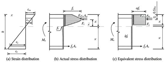
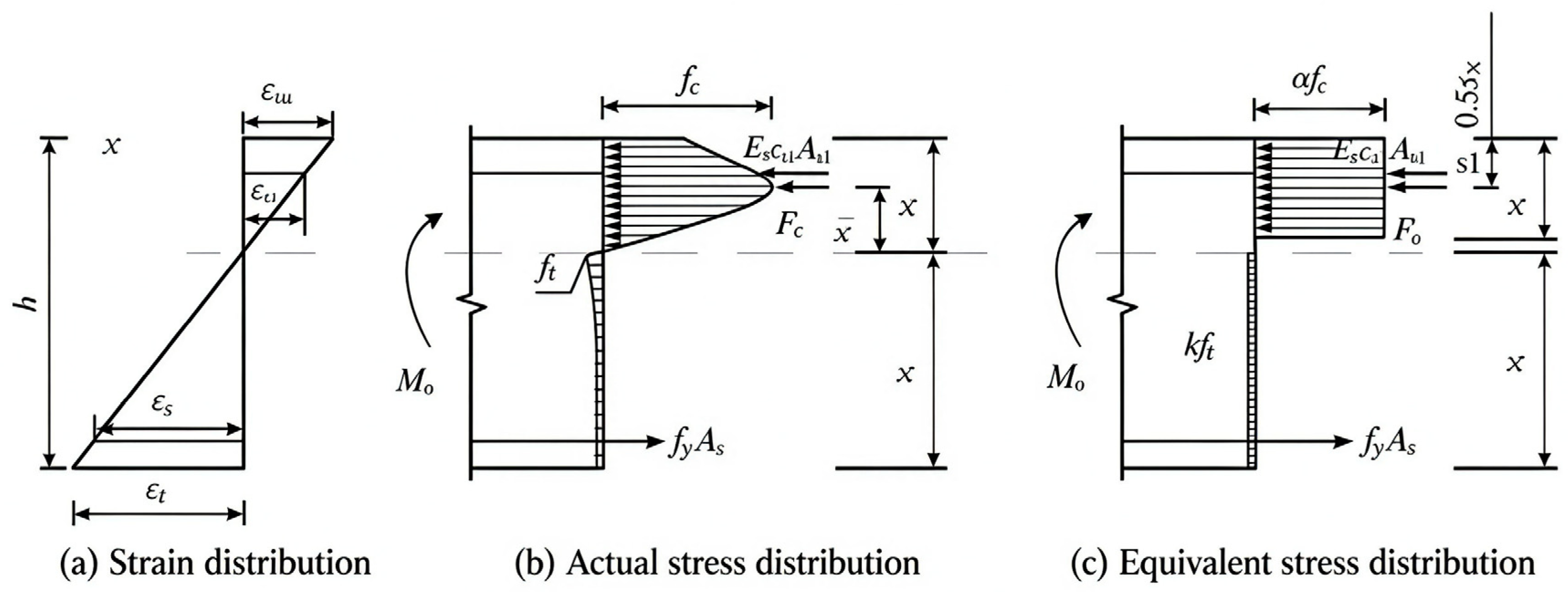
According to test observations, UHPC in the tension zone cracks first under increasing load; subsequently, longitudinal tensile reinforcement yields. As load further increases, the neutral axis moves upward into the flange plate, until UHPC at the extreme compression fiber of the section crushes, which corresponds to the ultimate limit state of positive-section flexural capacity of UHPC T-beams. At the ultimate flexural limit state, the sectional strain satisfies plane-section assumption. The actual nonlinear stress distribution and the equivalent rectangular stress block simplification adopted in this study are illustrated in Figure 12.
Figure 12.
Stress and strain distribution at ultimate flexural state of UHPC T-beam: (a) strain distribution; (b) actual stress distribution; (c) equivalent rectangular stress block distribution.
6.3. Equivalence of Compressive and Tensile Stress Blocks for UHPC
For engineering simplification, the nonlinear actual stress distribution is converted into regular rectangular stress blocks on the premise of identical resultant force magnitude and resultant force position. The total compressive resultant force of the UHPC compression zone is obtained via integration, as given in Equation (2):
where = compressive stress as a function of compressive strain; = sectional width function along beam depth, taken as flange width in this study.
The distance from the resultant compressive force to the neutral axis can be calculated from Equation (3):
Dimensional treatment for Equations (2) and (3) yields Equations (4) and (5):
where and are constants. The conversion coefficients α and β for the equivalent compression zone are expressed in Equations (6) and (7):
where = ratio of equivalent compression-zone depth to actual compression-zone depth ( = 0.83 in this work).
A coefficient is introduced to simplify tensile-zone stress distribution into rectangular stress blocks. The tensile resultant force is given by Equation (8):
where = web width; = web height; = flange thickness.
In this work, the compressive stress–strain constitutive relation of UHPC adopts the commonly used model for fiber-reinforced UHPC [28]. Only the compressive strength was experimentally measured in this study, while full compressive stress–strain curves were not tested. The equivalent rectangular stress block conversion coefficients and are derived via numerical integration over literature-reported compressive stress–strain curves, following equal resultant force and equal resultant force position principles [28]. This coefficient framework is applicable for both SF-UHPC and POM-UHPC. In sectional calculations, the material-specific compressive strength measured in the present test is adopted for each UHPC type. Other compressive material parameters required for sectional analysis are taken from published references.
6.4. Ultimate Flexural Capacity Formula for T-Section UHPC Beams
According to sectional internal force equilibrium from Figure 12c, the equilibrium condition is established as Equation (9):
From Figure 12a, compressive reinforcement strain satisfies Equation (10):
where = distance from centroid of compressive reinforcement to extreme compression fiber; = effective depth of section.
Substitute Equation (10) into Equation (9) to obtain a quadratic equation about equivalent compression-zone depth . Solve for and compute ultimate flexural capacity by Equation (11):
where = web width.
Back-calculation using experimental ultimate moment gives the fitting formulas for coefficient k versus longitudinal reinforcement ratio for POM-UHPC and SF-UHPC, as shown in Equations (12) and (13):
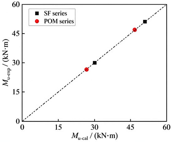
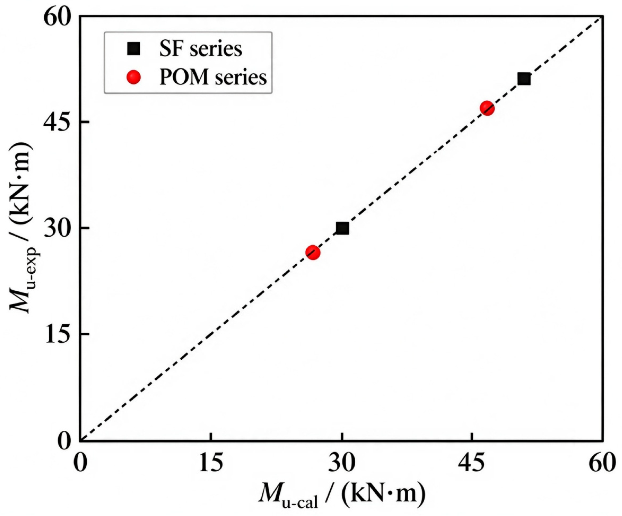
Coefficient increases with the reinforcement ratio, demonstrating that a higher reinforcement ratio enables better utilization of the tensile performance of UHPC. The tensile-zone modification coefficient is determined by Equations (12) and (13). Then Equations (9) and (10) are solved to obtain equivalent compression-zone depth, and finally the ultimate flexural capacity is computed via Equation (11). Comparisons between calculated and experimental values for four specimens are summarized in Table 8 and Figure 13. The mean ratio of calculated to experimental ultimate capacity (/) is 1.003, with a coefficient of variation of 0.96%, indicating that the calibrated formulas achieve good agreement against the present test dataset. It should be emphasized that the linear fitting expressions for and are obtained via calibration using only two reinforcement ratios for each fiber type. These formulas are limited to the investigated parameter range: 2% fiber volume fraction, longitudinal reinforcement ratio between 1.08% and 2.04%, and the T-beam geometric configuration adopted in this study. Extrapolation to other parameter ranges requires further experimental verification.
Table 8.
Comparison between calculated and experimental ultimate flexural capacity of T-beam specimens.
Figure 13.
Comparison between experimental ultimate moment and calculated ultimate moment.
7. Conclusions
- (1)
- Material mechanical performance: The full replacement of steel fibers with low-modulus POM synthetic fibers results in a significant reduction in the mechanical strength of UHPC. In this test, the compressive strength of POM-UHPC decreases by approximately 20% compared with SF-UHPC. Its uniaxial tensile behavior transfers from strain-hardening to strain-softening, with deteriorated ultimate tensile strength and toughness. This is mainly attributed to the low elastic modulus of POM fibers, which provides weaker matrix confinement and lower efficiency of post-crack stress transfer compared with steel fibers.
- (2)
- Component flexural performance: Differences in material strength directly affect the ultimate bearing capacity of beams. Under identical longitudinal reinforcement ratios, SF-UHPC T-beams possess higher flexural capacity than POM-UHPC T-beams. Hence, SF-UHPC remains a preferred solution for load-bearing components requiring high ultimate capacity.
- (3)
- Failure mode and toughness: Despite lower bearing capacity, POM-UHPC T-beams exhibit distinctive failure patterns. Cracks develop sufficiently and form dense, uniform reticular micro-crack systems, in contrast with SF-UHPC beams characterized by concentrated cracks and wide primary cracks. Although POM fibers deliver low peak crack-bridging stress, their excellent dispersibility facilitates multi-crack development, enabling more energy dissipation before failure and superior deformability and ductility.
- (4)
- Based on the plane-section assumption and stress block equivalence principle, ultimate flexural capacity calculation formulas are proposed for POM-UHPC and SF-UHPC T-beams, introducing a tensile-zone stress modification coefficient related to fiber type and longitudinal reinforcement ratio. For four tested specimens, the mean value of the ratio of calculated to experimental capacity reaches 1.003 with a coefficient of variation of 0.96%, which demonstrates that the calibrated formulas fit well for specimens within the present test parameter scope. Further experimental data are required for broader-range validation.
- (5)
- Engineering application perspectives: SF-UHPC and POM-UHPC represent two technical routes with different performance priorities for UHPC structures. SF-UHPC is suitable for primary load-bearing structures pursuing high strength. POM-UHPC shows the intrinsic advantages of corrosion resistance, lightweight performance, and favorable crack-control performance. Its capacity loss can be compensated by enhancing the reinforcement ratio via structural design. Accordingly, POM-UHPC exhibits attractive prospective merits for potential engineering scenarios such as sea-crossing bridges and saline–alkali corrosive environments with high durability and low self-weight requirements. It should be noted that this inference is based on the intrinsic material property of corrosion resistance of POM fibers; relevant durability and long-term performance tests are not performed in this work and require further verification before practical deployment.
Author Contributions
Conceptualization, S.L. and L.D.; methodology, S.L. and H.S.; software, R.Z.; validation, S.L., L.D. and H.S.; formal analysis, H.S.; investigation, S.L.; resources, L.D.; data curation, R.Z.; writing—original draft preparation, S.L.; writing—review and editing, L.D., H.S. and R.Z.; visualization, R.Z.; supervision, L.D.; project administration, L.D.; funding acquisition, L.D. All authors have read and agreed to the published version of the manuscript.
Funding
This research was funded by Sichuan Provincial Key Research and Development Program, grant number 2024YFTX0037; and Shaanxi Provincial Department of Transport Research Project, grant number 23-46K. The APC was funded by Southwest Jiaotong University.
Data Availability Statement
The raw experimental data generated in this study are available from the corresponding author upon reasonable request.
Acknowledgments
The authors acknowledge the technical support provided by the laboratory staff during specimen preparation and testing.
Conflicts of Interest
Author Sai Liu was employed by Wenzhou Expressway Operation and Management Co., Ltd. Author Litao Dang was employed by China Communications Ruitong Road & Bridge Maintenance Technology Co., Ltd. The remaining authors declare that the research was conducted in the absence of any commercial or financial relationships that could be construed as a potential conflict of interest.
Abbreviations
UHPC, Ultra-High-Performance Concrete; POM, Polyoxymethylene; SF, Steel Fiber; LVDT, Linear Variable Differential Transformer.
References
- Bache, H.H. Compact Reinforced Composite Basic Principles; Aalborg Portland: Aalborg, Denmark, 1987. [Google Scholar]
- Niwa, J. Recommendations for Design and Construction of Ultra High Strength Reinforced Concrete Structures; Japan Society of Civil Engineers: Tokyo, Japan, 2006. [Google Scholar]
- Yao, S.; Yang, Z.P.; Ge, W.J.; Hu, Y.; Li, W.; Sun, C.; Yan, W.; Cao, D. Analysis on workability and mechanical properties of ultra-high-performance concrete. Build. Struct. 2023, 53, 142–147. [Google Scholar]
- Zhang, Y.H.; Ren, S.H.; Yuan, S.L. Review on application of prefabricated building connections based on UHPC in China. Build. Struct. 2023, 53, 1200–1205. [Google Scholar]
- Gao, C.Y.; Tang, T. Study on size effect on shear performance of UHPC beams without stirrups. Build. Struct. 2022, 52, 1435–1441. [Google Scholar]
- Zhou, B.; Uchida, Y. Relationship between fiber orientation/distribution and post-cracking behaviour in ultra-high-performance fiber-reinforced concrete (UHPFRC). Cem. Concr. Compos. 2017, 83, 66–75. [Google Scholar] [CrossRef] [Scilit]
- Yoo, D.Y.; Banthia, N.; Kang, S.T.; Yoon, Y.-S. Effect of fiber orientation on the rate-dependent flexural behavior of ultra-high performance fiber-reinforced concrete. Compos. Struct. 2016, 157, 62–70. [Google Scholar] [CrossRef] [Scilit]
- Song, Q.; Yu, R.; Shui, Z.; Rao, S.; Wang, X.; Sun, M.; Jiang, C. Steel fibre content and interconnection induced electrochemical corrosion of ultra-high performance fibre-reinforced concrete (UHPFRC). Cem. Concr. Compos. 2018, 94, 191–200. [Google Scholar] [CrossRef] [Scilit]
- Shin, W.; Yoo, D.Y. Influence of steel fibers corroded through multiple microcracks on the tensile behavior of ultra-high-performance concrete. Constr. Build. Mater. 2020, 259, 120428. [Google Scholar] [CrossRef] [Scilit]
- Ma, M.L.; Yang, H.; Bai, B.; Xie, G.Q. Research on effect of polyoxymethylene fiber on mechanical properties of ultra-high-performance concrete. Concrete 2022, 11, 101–105. [Google Scholar]
- Cheng, S.X.; Li, C.Y.; Hui, W.H.; Li, J.; Zhang, Y.; Ding, Q.; He, T. Effect of polyoxymethylene fiber on properties of ultra-high-performance concrete. Concrete 2025, 5, 210–213. [Google Scholar]
- Wang, H.; Shen, C.; Tang, D.S.; Lv, Z.Q.; Yang, C.H.; Yu, L.W.; Ye, J.X. Research on mechanical properties of UHPC modified by polyoxymethylene fiber. New Build. Mater. 2025, 52, 134–139. [Google Scholar]
- Ban, P.H.; Zhou, X.; Wang, H.; Zhong, H.W.; Yang, Z.Q.; Lin, Y.; Liu, J.Z.; Han, F.Y. Performance and application of decorative UHPC reinforced by high-performance POM fiber. Concrete 2023, 8, 182–186. [Google Scholar]
- Xia, Y.H.; Yang, D.Y.; Zhao, L.; Qian, Y.F.; Gao, H. Mechanical properties of ultra-high-strength concrete reinforced by POM macro-fibers. Compos. Sci. Eng. 2022, 52–57+92. [Google Scholar]
- Deng, Z.C.; Li, H.C.; Huang, S. Flexural toughness and impact resistance of hybrid-fiber ultra-high-performance concrete. J. Harbin Eng. Univ. 2025, 46, 2506–2513. [Google Scholar]
- Zheng, F.; Li, C.X.; Yoo, D.Y.; Pan, R.; He, J.; Ke, L. Flexural and cracking behaviors of reinforced UHPC beams with various reinforcement ratios and fiber contents. Eng. Struct. 2021, 248, 113266. [Google Scholar] [CrossRef] [Scilit]
- Gao, Y.Q.; Wang, J.Y. Flexural behavior of high-strength steel bar reinforced UHPC beams with considering restrained shrinkage. Constr. Build. Mater. 2023, 409, 133802. [Google Scholar] [CrossRef] [Scilit]
- Gao, X.; Wang, M.; Guo, J.; Li, H. Flexural behaviors of a novel precast hollow UHPC composite beam reinforced with inverted T-shaped steel: Experimental investigation and theoretical analysis. J. Build. Eng. 2024, 86, 108893. [Google Scholar] [CrossRef] [Scilit]
- Jing, X.; Wang, Q.; Tao, Y.; Jiang, M. Mechanical properties of steel-PVA hybrid fiber UHPC under uniaxial compression and mesoscale numerical simulation. Constr. Build. Mater. 2026, 537, 147098. [Google Scholar] [CrossRef] [Scilit]
- Wang, W.; Guo, H.; Han, T.; Wang, Q.; Wang, Y. Low-carbon UHPC incorporating GGBS–calcium carbide slag and recycled plastic fibers: Mechanical properties, hydration, and sustainability. Materials 2026, 19, 3277. [Google Scholar] [CrossRef] [Scilit]
- Li, Y.; Peng, Z.L.; Li, J.Z.; Shi, Y. Research on effect of polyoxymethylene (POM) fiber on workability and mechanical properties of concrete. Build. Struct. 2022, 52, 1004–1009. [Google Scholar]
- Zhang, L.H.; Liu, J.Z.; Zhou, H.X.; Yang, Z.Q. Influence of polyoxymethylene fiber on concrete properties. Concr. Cem. Prod. 2018, 58–62. [Google Scholar]
- Zhang, L.H.; Zhou, H.X.; Liu, J.Z. Research on plastic cracking resistance of polyoxymethylene fiber reinforced mortar. New Build. Mater. 2018, 45, 48–52. [Google Scholar]
- Liu, Z.; Wang, G.J.; Wang, M.L. Research on mechanical properties and toughening mechanism of shotcrete with different POM fiber contents. J. Chongqing Univ. 2026, 49, 44–54. [Google Scholar]
- Ma, R.; Qiu, J.J.; Wang, E.H. Research progress on performance improvement of high-performance concrete by polyoxymethylene fiber. Mater. Rep. 2026, 40, 131–143. [Google Scholar]
- GB 175-2007; Common Portland Cement. China Standards Press: Beijing, China, 2007.
- GB 50010-2010; Ministry of Housing and Urban-Rural Development of the People’s Republic of China. Code for Design of Concrete Structures. China Architecture & Building Press: Beijing, China, 2011.
- Zhang, R.; Zhao, R.; Liu, Z.L.; Hu, P.; Chen, K.D.; Li, X. Effects of Longitudinal Reinforcement Ratio on Flexural Capacity of One-Way Slab of UHPC Waffle Bridge Deck. J. Southwest Jiaotong Univ. 2023, 58, 1432–1439. [Google Scholar]

Disclaimer/Publisher’s Note: The statements, opinions and data contained in all publications are solely those of the individual author(s) and contributor(s) and not of MDPI and/or the editor(s). MDPI and/or the editor(s) disclaim responsibility for any injury to people or property resulting from any ideas, methods, instructions or products referred to in the content. |
© 2026 by the authors. Licensee MDPI, Basel, Switzerland. This article is an open access article distributed under the terms and conditions of the Creative Commons Attribution (CC BY) license.