


Abstract
Conventional concrete-filled steel tubular (CFST) column–steel beam joints are susceptible to irreversible plastic damage at beam ends, column walls, and joint cores during strong earthquakes, complicating post-earthquake repair. This study proposes a novel fully bolted prefabricated joint with replaceable double-channel energy-dissipating components to improve damage control and repairability. Preferential yielding, plastic deformation, and local buckling of the channels dissipate seismic energy, limiting damage to the primary members and joint core. A detailed finite element model was developed based on existing experimental data to assess the joint’s seismic performance. Plastic strain concentrated in the channels, while the main steel beam, CFST column, and steel sleeve sustained limited damage. The load-transfer analysis clarified the roles of the channel flanges and webs in transferring bending-induced axial forces and shear, respectively. Compared with a monolithic external-diaphragm joint, the proposed joint localized damage more effectively within the replaceable channels, with 20.6% higher initial stiffness and approximately 40% greater total energy dissipation. Increasing channel thickness from 4 to 10 mm increased peak load, initial stiffness, displacement ductility factor, and cumulative energy dissipation by 27.7%, 33.0%, 18.0%, and 69.8%, respectively. Increasing channel length from 360 to 630 mm reduced peak load and initial stiffness by 21.8% and 42.4%, respectively, while increasing ultimate displacement by 43.5%; cumulative energy dissipation peaked at 540 mm. Increasing the axial compression ratio from 0.1 to 0.4 had little effect on peak load but reduced ultimate displacement and cumulative energy dissipation by 10.2% and 23.0%, respectively. Within the investigated joint dimensions and parameter ranges, a channel thickness of 8 mm and an axial compression ratio of 0.1–0.2 are recommended. Larger slip displacement intensified hysteretic pinching and reduced load-bearing capacity and energy dissipation. A simplified yield-load equation was developed, with relative errors within 10% compared with the results of 15 finite element models. A channel length of 540 mm is preferred when prioritizing energy dissipation and deformation capacity, whereas 450 mm is preferred when prioritizing strength and initial stiffness.
1. Introduction
Concrete-filled steel tube (CFST) columns offer high load-bearing capacity and good ductility through the composite action of the steel tube and concrete core. These advantages, together with efficient construction, have led to their widespread use in multistory and high-rise buildings, long-span structures, and heavy-duty industrial buildings [1]. Beam–column joints transfer bending moments, shear forces, and axial forces in CFST frames, and their mechanical behavior and failure modes directly affect overall seismic safety. Common CFST column–steel beam connections include external diaphragms, internal diaphragms, through diaphragms, and side plates. Previous studies have systematically examined their strength, stiffness, panel-zone shear response, and development of plastic deformation [2,3,4,5]. However, conventional joints typically dissipate seismic energy through beam-end plastic hinges, connection-plate yielding, or panel-zone shear deformation. During strong earthquakes, damage may spread to the main beams, column walls, and joint cores. These damaged regions are difficult to remove and replace, hindering rapid post-earthquake functional recovery [6,7,8,9].
High-strength bolted connections have increasingly been adopted in CFST column–steel beam joints to reduce on-site welding and improve assembly efficiency. Zhang et al. [10] proposed a joint with on-site bolted beam-flange splices, using local beam-end reinforcement to improve load-bearing and deformation capacities. Fan et al. [11] developed a hysteretic model for fully bolted steel beam-CFST column joints. Chu et al. [12] developed a fully bolted beam–column joint incorporating a core tube and demonstrated its ductility and energy dissipation capacity. Subsequent configurations included fully bolted external-diaphragm joints, connections with partially encased composite beams, and blind-bolted connections [13,14,15]. These joints reduce on-site welding and facilitate component standardization, but their benefits primarily concern construction. Plastic energy dissipation remains concentrated at beam ends, splice plates, or panel zones, and post-earthquake repair often involves primary structural members.
As seismic design objectives shift from collapse prevention toward damage control and post-earthquake functional recovery, incorporating replaceable energy-dissipating components at designated plastic hinge locations has become a key strategy for resilient joints. Preferential yielding of removable components localizes seismic damage in regions that are readily inspected and replaced. He et al. [16] proposed a steel–concrete composite connection with replaceable angle fuses and identified a load-transfer mechanism combining axial action in the angles with shear resistance of the connection plates. Men et al. [17] investigated steel beam–column joints with replaceable T-shaped connectors, showing that damage localization requires an appropriate strength balance between the energy-dissipating components and primary members. Zheng et al. [18] improved joint plastic deformation capacity using replaceable components at the lower beam flange. Replaceable cover plates on both beam flanges, buckling-restrained flange plates, and other structural fuses have also been adopted to improve energy dissipation stability and post-earthquake repairability [19,20,21,22].
Further developments include connections with staged yielding, frictional energy dissipation, and combined dissipation mechanisms. These connections limit plastic damage to the primary structure through flexural or shear yielding of steel plates, frictional slip in bolted connections, and multistage energy dissipation [23,24,25,26,27,28,29]. However, the performance of joints with replaceable components is sensitive to the strength, stiffness, effective deformation length, and local stability of the energy-dissipating components. Excessive component strength may transfer plastic damage to the primary beams and columns, whereas insufficient strength or effective length may cause premature buckling and strength degradation. Although bolted connections facilitate assembly and replacement, interface slip may induce hysteretic pinching, creating complex trade-offs among joint stiffness, energy dissipation, and damage control. Integrating prefabricated connections, structural fuses, and protection of primary members offers an effective approach to improving seismic resilience [30,31,32,33,34,35,36,37].
Despite these advances in CFST column–steel beam joint configurations, research integrating fully bolted assembly with replaceable energy-dissipating components remains limited. Joints that dissipate energy through local buckling of thin-walled steel components, load paths, and hysteretic pinching and the effects of detailing parameters on damage distribution require further investigation.
This study therefore proposes a novel prefabricated CFST column–steel beam joint with replaceable double-channel energy-dissipating components. Compared with the plate-, T-stub-, and angle-based fuse configurations reviewed above, the proposed joint features two channels arranged symmetrically on either side of the beam web. Their integrated flange–web geometry combines moment transfer, shear transfer, and designated regions for inelastic deformation within the same pair of removable components. The channel flanges primarily transfer the tensile and compressive forces associated with beam bending, while the webs primarily transfer shear. Channel thickness and length provide parameters for adjusting connection stiffness, resistance, and deformation capacity. Preferential yielding and plastic deformation of the channels are intended to localize damage in the replaceable components and limit damage to the primary structural members. Following validation of the modeling approach against published experimental data, detailed finite element analyses were conducted to evaluate the joint’s seismic performance. The effects of channel thickness, channel length, axial compression ratio, and slip displacement on hysteretic response, stiffness degradation, ductility, and energy dissipation were investigated. A simplified equation for predicting the joint yield load was also developed and assessed against the finite element results.
2. Joint Configuration and Working Mechanism
2.1. Joint Configuration
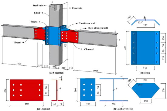
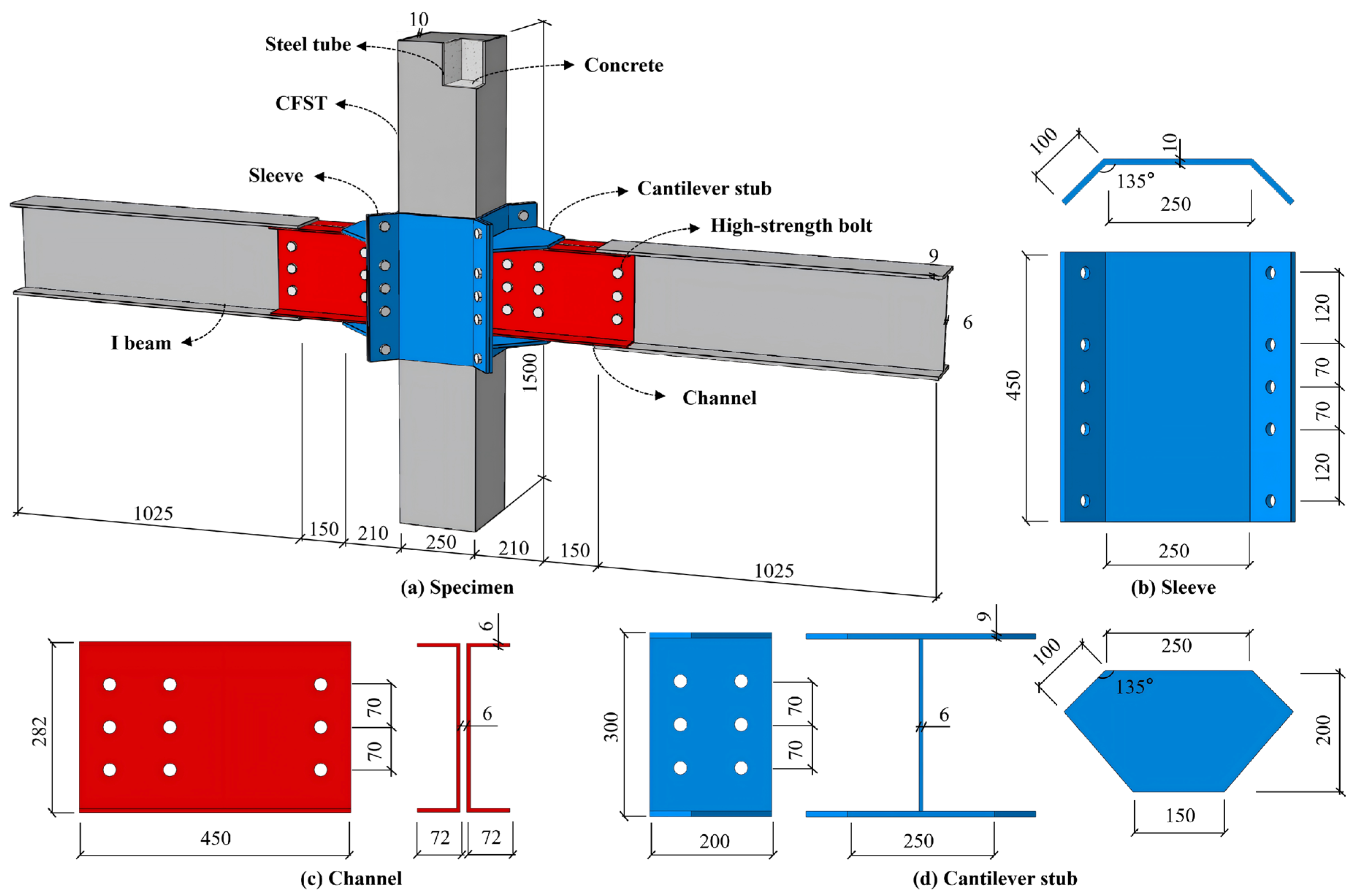
This study proposes a novel prefabricated CFST column–steel beam joint with replaceable double-channel energy-dissipating components. The joint comprises a CFST column, an external steel sleeve, cantilever stub beams, steel beams, paired energy-dissipating channels, and high-strength bolts (Figure 1). The steel sleeve surrounds the CFST column, with cantilever stub beams welded to both sides during factory fabrication to form a stiff beam–column connection region. The main steel beam is spliced to the cantilever stub beam through two channels arranged symmetrically on either side of the beam web. High-strength bolts are used for on-site assembly.
Figure 1.
Configuration and geometric dimensions of joint: (a) specimen; (b) sleeve; (c) channel; (d) cantilever stub.
The CFST column is 1500 mm high, with a cross-section of 250 mm × 250 mm and a tube wall thickness of 10 mm. The main steel beam and cantilever stub beams have H-sections with a depth of 300 mm, a flange width of 150 mm, and web and flange thicknesses of 6 and 9 mm, respectively. The main beam is 1025 mm long. The steel sleeve is 450 mm high and 250 mm wide, with a plate thickness of 10 mm, a projecting inclined edge length of 100 mm, and a transition angle of 135°. Each replaceable channel is 450 mm long and 282 mm deep, with a flange width of 72 mm and a web and flange thickness of 6 mm. The bolt-hole spacing along the channel depth is 70 mm. Q355 steel is used for the steel tube, beams, sleeve, stub beams, and channels, while the concrete core has a strength grade of C60. The connections use M22 high-strength friction-grip bolts of property class 12.9. The joint design and detailing were based on the relevant provisions of the Code for Seismic Design of Buildings (GB 50011-2010) [38] and the Standard for Design of Steel Structures (GB 50017-2017) [39].
2.2. Working Mechanism
Under cyclic seismic loading, the beam-end moment is transferred to the paired channels primarily through the tension–compression force couple developed in the upper and lower flanges. Beam-end shear is resisted jointly by the channel webs, bolt groups, and bearing at the bolt-hole walls. Internal forces pass through the channels to the cantilever stub beams and are distributed to the CFST column through the steel sleeve, reducing local stress concentrations in the column wall. During initial loading, force transfer across the connection interfaces relies primarily on friction generated by bolt pretension, providing high initial stiffness. As loading increases, relative slip at the contact interfaces induces hysteretic pinching. As the bolt shanks engage the hole walls, load transfer progressively involves the combined action of friction, bearing, and component deformation. The channels yield first and develop local buckling at larger deformations, becoming the primary energy-dissipating components. An appropriate strength balance between the channels and primary members can confine the principal nonlinear deformation to the removable channels, reduce plastic damage to the main steel beam, CFST column, and steel sleeve, and facilitate post-earthquake replacement of damaged channels.
3. Finite Element Model
3.1. Material Constitutive Models
The concrete core was modeled using the concrete damaged plasticity (CDP) model. The parameters included a dilation angle of 39°, a flow potential eccentricity of 0.1, a biaxial-to-uniaxial compressive strength ratio of 1.16, a stress invariant ratio of 0.667, a viscosity parameter of 0.0001, and a Poisson’s ratio of 0.2. The concrete constitutive relationship accounted for confinement by the steel tube and followed the Technical Code for Concrete Filled Steel Tubular Structures (GB 50936-2014) [40]. Q355 steel was represented by a multilinear elastoplastic model, with an elastic modulus of 2.06 × 10⁵ MPa and a Poisson’s ratio of 0.3.
3.2. Model Setup
The finite-element models were developed using Abaqus. Surface-to-surface contact was defined between the square steel tube and the concrete core. Hard contact was specified in the normal direction, while a penalty friction formulation with a coefficient of 0.6 was used in the tangential direction. The interfaces between the paired channels and the main steel beam, cantilever stub beams, and high-strength bolts also used hard normal contact and tangential friction, with a friction coefficient of 0.45. Welded regions between the cantilever stub beams and steel sleeve were modeled using tie constraints.
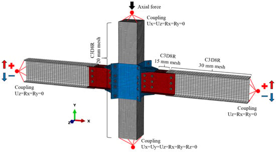
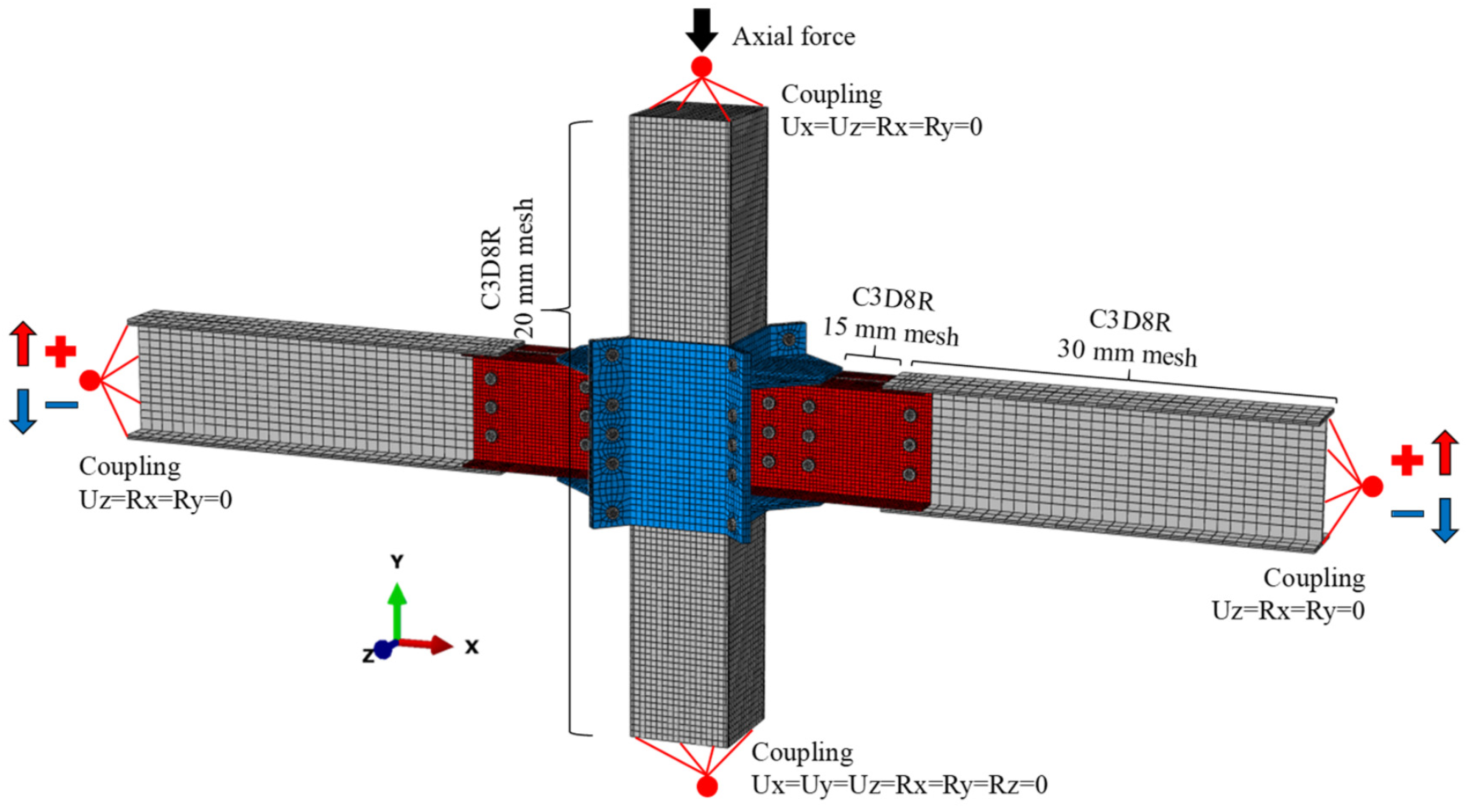
The mesh, boundary conditions, and loading arrangement are shown in Figure 2. All components were modeled using C3D8R reduced-integration solid elements, with structured and swept meshing. A locally refined mesh size of 15 mm was used in the joint core, double-channel connection regions, and around bolt holes. Mesh sizes of 20 and 30 mm were assigned to the CFST column and the main steel beam away from the joint, respectively. The column base was fully fixed. The column top face was coupled to a reference point, where Ux, Uz, Rx, and Ry were restrained, leaving vertical translation and in-plane rotation free. The left and right beam ends were coupled to separate reference points, with out-of-plane translation (Uz) and rotations Rx and Ry restrained. Vertical cyclic displacements were applied through these reference points.
Figure 2.
Boundary conditions and mesh of finite element model.
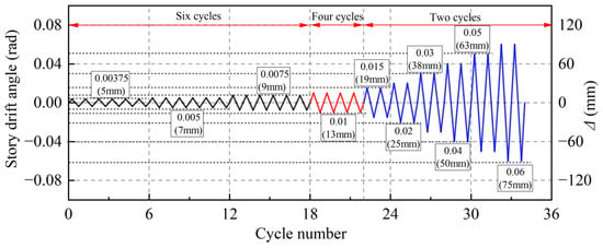
Loading was applied in three stages. First, an axial pretension of 155 kN was applied to each high-strength bolt, and the pretension state was retained in subsequent analysis steps. The clamping force generated by bolt pretension provides frictional resistance to vertical sliding at the connection interfaces. During cyclic loading, relative slip may occur when the tangential force demand exceeds the available frictional resistance. Next, a constant axial load of 500 kN, corresponding to an axial compression ratio of 0.1, was applied at the column top. Finally, displacement-controlled low-cycle reversed loading was applied to both beam ends using a protocol based on AISC 341-16 [41]. The loading history is shown in Figure 3.
Figure 3.
Cyclic loading protocol.
3.3. Model Verification
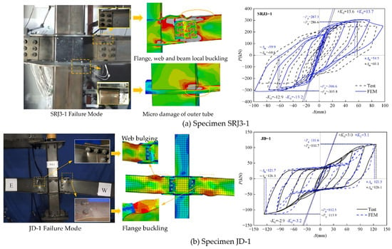
To assess the reliability of the adopted modeling approach, two published specimens of prefabricated bolted beam-to-column connections with external diaphragms were selected for validation: SRJ3-1 reported by Zhang et al. [42] and JD-1 reported by Wang et al. [43]. The corresponding FE models were established using the reported geometric dimensions, material properties, connection details, and loading protocols of the respective specimens. Figure 4 compares the experimental and numerical failure modes and hysteretic curves for both specimens.
Figure 4.
Comparison of failure modes and hysteretic curves: (a) Specimen SRJ3-1; (b) Specimen JD-1.
For SRJ3-1, the FE model reproduces the principal failure locations and local deformation characteristics, and the simulated hysteretic response agrees well with the experimental results. The relative differences in ultimate bearing capacity and initial stiffness are 1.4% and 2.3%, respectively. For JD-1, the model also captures the observed failure characteristics and the distinct Z-shaped hysteretic response. The corresponding differences in ultimate bearing capacity and initial stiffness are 1.2% and 8.3%, respectively. These comparisons provide further support for the adopted modeling approach in predicting the failure modes and cyclic responses of related bolted connections.
4. Seismic Performance Assessment
4.1. Failure Mode
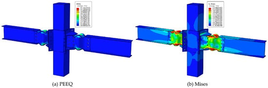
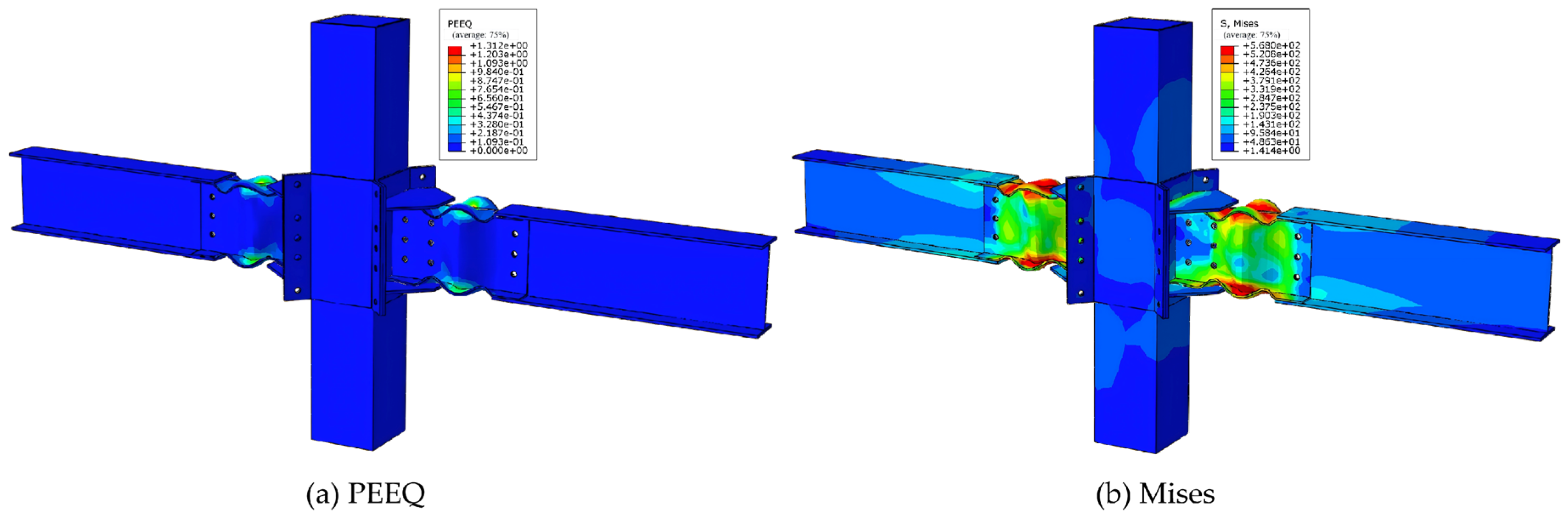
Figure 5 presents the typical failure mode and stress distribution of the proposed joint under cyclic loading. As shown in Figure 5a, equivalent plastic strain (PEEQ) concentrates in the paired channels, with pronounced plastic zones developing in their flanges and webs. Plastic strains in the main steel beam, CFST column, and steel sleeve remain low, indicating that the principal nonlinear deformation is localized in the replaceable channels. As cyclic displacement increases, the channels progressively yield under repeated tension and compression and develop local buckling in the connection regions, forming the primary mechanism for plastic energy dissipation. The von Mises stress distribution in Figure 5b shows high stresses concentrated in the paired channels, around bolt holes, and in the connection regions adjacent to the cantilever stub beams, with stress levels decreasing outward along the beam. The CFST column and steel sleeve exhibit relatively low stresses, without extensive plastic zones. These results indicate that the paired channels yield preferentially and provide most of the cyclic energy dissipation, limiting damage to the primary beams and columns and achieving the intended damage localization and member protection.
Figure 5.
Failure mode and stress distribution of the proposed joint: (a) PEEQ; (b) Mises.
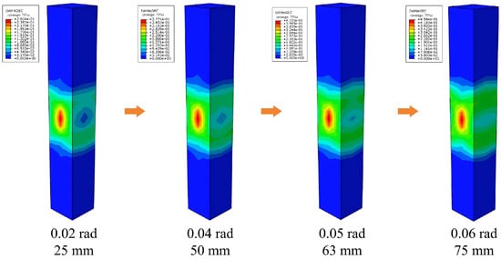
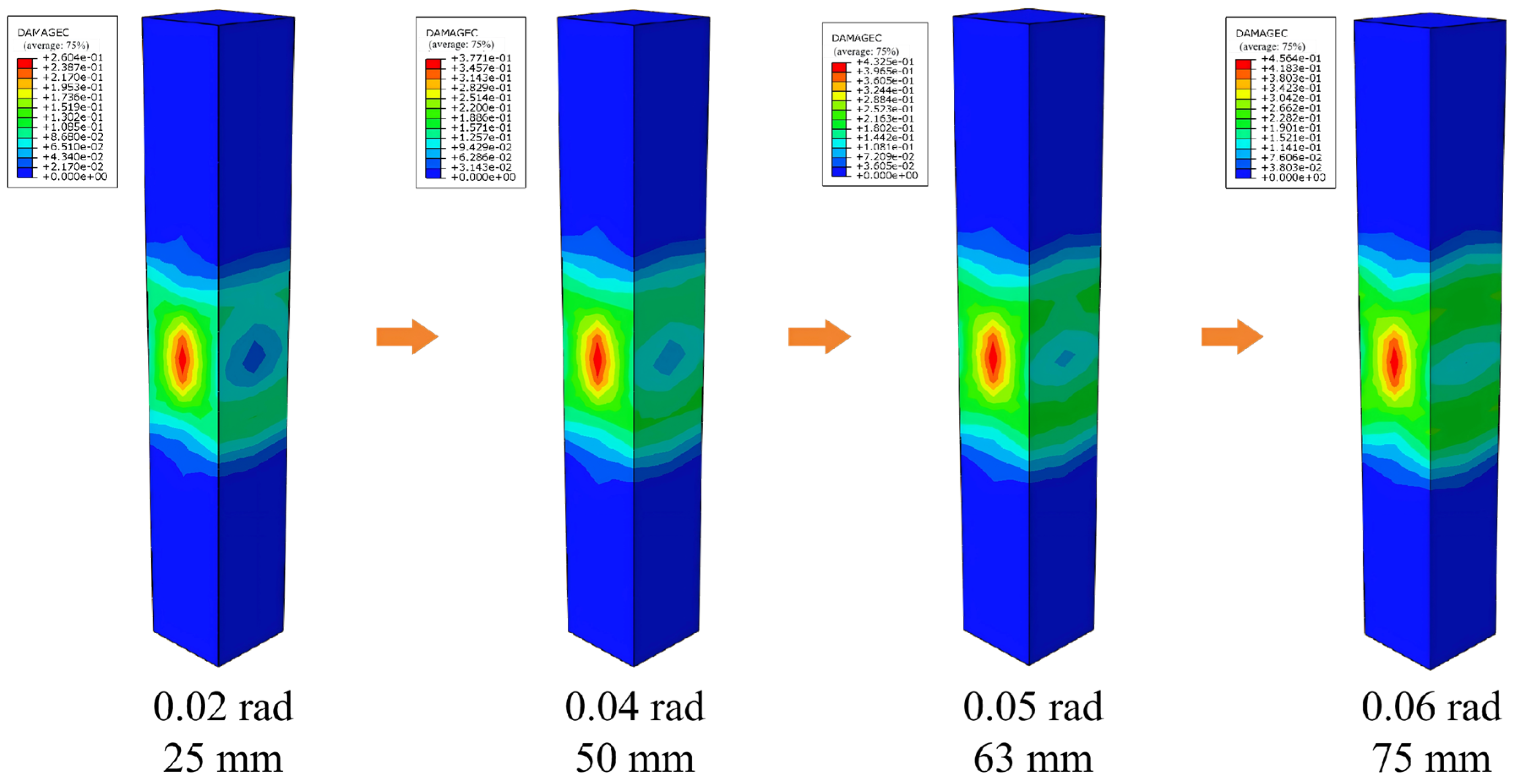
Figure 6 illustrates the evolution of compressive damage in the concrete core at beam-end displacement amplitudes of 25, 50, 63, and 75 mm. The displayed maximum DAMAGEC values increase from approximately 0.260 at 25 mm to 0.377, 0.433, and 0.456 at 50, 63, and 75 mm, respectively. Compressive damage is concentrated in the central region corresponding to the joint, whereas the upper and lower regions exhibit substantially lower damage values.
Figure 6.
Evolution of damage in the concrete core.
4.2. Load Transfer Paths
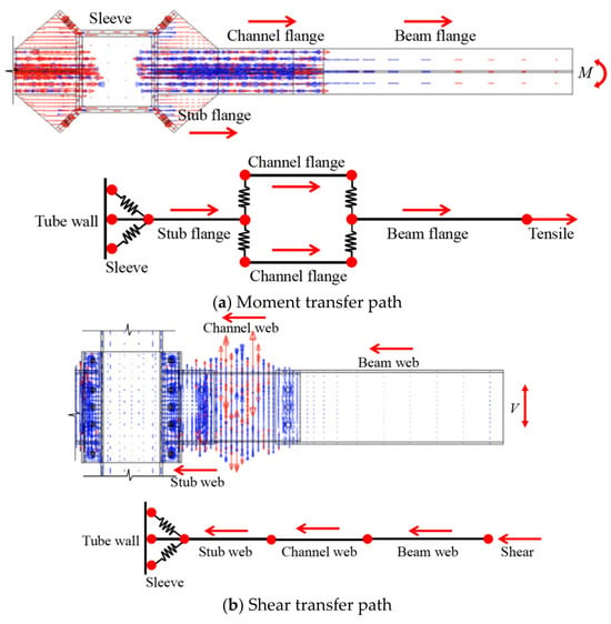
Figure 7 illustrates the principal paths for transferring beam-end moment and shear, shown in Figure 7a and Figure 7b, respectively.
Figure 7.
Load transfer mechanism of the proposed joint: (a) Moment transfer path; (b) Shear transfer path.
As shown in Figure 7a, the beam-end moment is resisted primarily by a tension–compression force couple in the upper and lower flanges. Axial forces in the beam flanges pass through the high-strength bolted connections to the channel flanges and then to the cantilever stub beam flanges. These forces are subsequently transferred through the stub beam–sleeve connections to the steel sleeve and distributed to the CFST column wall. The principal moment transfer path is therefore: steel beam flanges → channel flanges → cantilever stub beam flanges → steel sleeve → CFST column wall. Under cyclic loading, axial tensile and compressive deformations concentrate in the channel flanges between the main steel beam and the rigid joint region, promoting preferential channel yielding and plastic energy dissipation.
Beam-end shear is transferred primarily through the webs, as shown in Figure 7b. Shear carried by the steel beam web passes through the bolt groups and connection interfaces to the paired channel webs, then to the cantilever stub beam web, and finally through the steel sleeve to the CFST column. The shear transfer path is therefore steel beam web → channel webs → cantilever stub beam web → steel sleeve → CFST column wall. The channel flanges and webs thus provide distinct paths for moment and shear transfer to the joint core, respectively. The replaceable paired channels serve as the key load-transfer and energy-dissipating components between the main steel beam and the joint core.
Table 1 and Table 2 summarize the moment and shear force distributions at four representative cyclic loading amplitudes. The channel flanges account for the largest moment share, ranging from 44.94% to 46.27%. The corresponding shares of the cantilever stub flanges, sleeve wall, and main beam flanges are 21.62~24.06%, 18.50~20.23%, and 12.03~13.21%, respectively. For shear transfer, the main beam web accounts for 33.52~37.22%, followed by the channel webs at 29.70~30.30%. The cantilever stub beam web and sleeve wall account for 14.83~18.10% and 16.22~18.49%, respectively. These proportions show relatively limited variation across the selected loading amplitudes, with the paired channels participating substantially in both moment and shear transfer.
Table 1.
Moment distribution among joint components.
Table 2.
Shear force distribution among joint components.
4.3. Comparative Analysis of Joint Configurations
A monolithic external-diaphragm joint was used as a reference to assess the seismic performance of the proposed prefabricated joint. Stress distributions, hysteretic responses, energy dissipation, and stiffness degradation were compared using identical beam and column cross-sections, material properties, boundary conditions, and loading protocols.
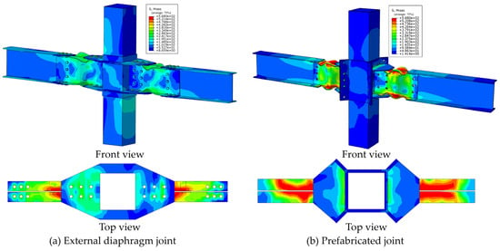
Figure 8 compares the von Mises stress distributions at the same loading stage. In the external-diaphragm joint, high stresses occur mainly in the paired channels, external diaphragms, and adjacent column walls, extending into the main steel beam and CFST column. This indicates that beam-end forces are transferred primarily through the external diaphragms directly to the column wall, with greater participation of the primary members in plastic deformation. In the prefabricated joint, high stresses are largely confined to the paired channels and their connections to the cantilever stub beams, while stresses in the main steel beam, CFST column, and steel sleeve remain relatively low. The prefabricated configuration thus promotes plastic deformation while concentrating the principal nonlinear response in the replaceable connection components, resulting in more distinct damage localization.
Figure 8.
Comparison of von Mises stress distributions between the two joint configurations: (a) External diaphragm joint; (b) Prefabricated joint.
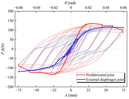
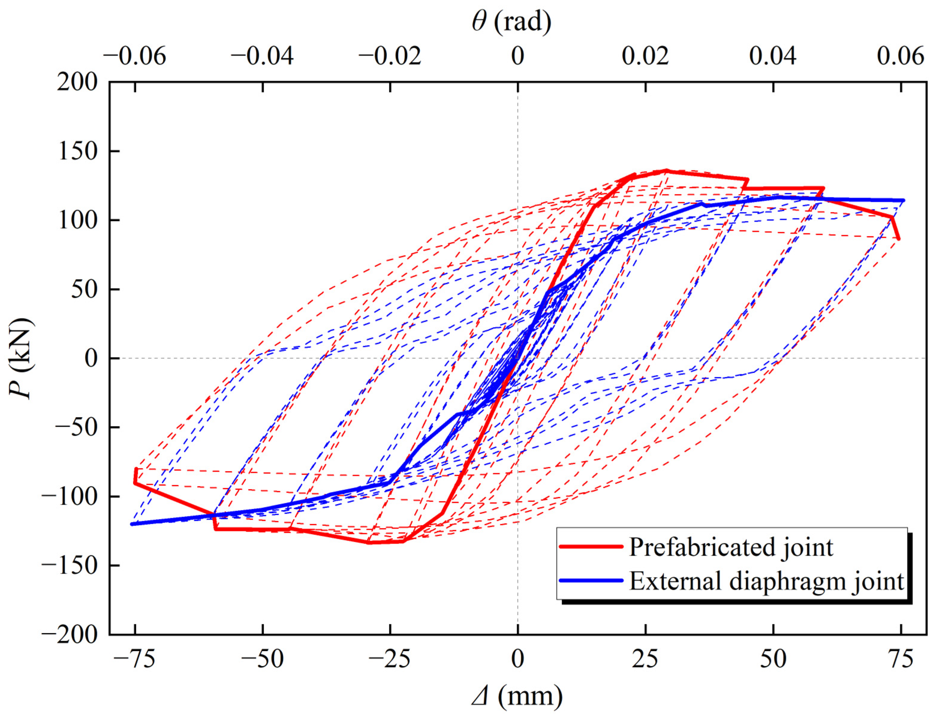
Figure 9 shows the hysteretic curves of the two joints. Both exhibit approximately linear elastic responses during initial loading, with hysteresis loop areas increasing as cyclic displacement increases. Interface slip and plastic deformation induce some pinching in both joints. However, the prefabricated joint develops fuller loops at moderate and large displacements, with slightly higher positive and negative peak loads. Its hysteresis envelope encloses a larger area while maintaining high load-bearing capacity. Progressive yielding and local buckling of the paired channels under repeated tension and compression sustain plastic deformation over a wider displacement range, improving hysteretic energy dissipation.
Figure 9.
Comparison of hysteretic responses between the two joints.
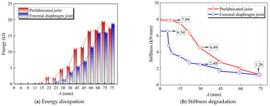
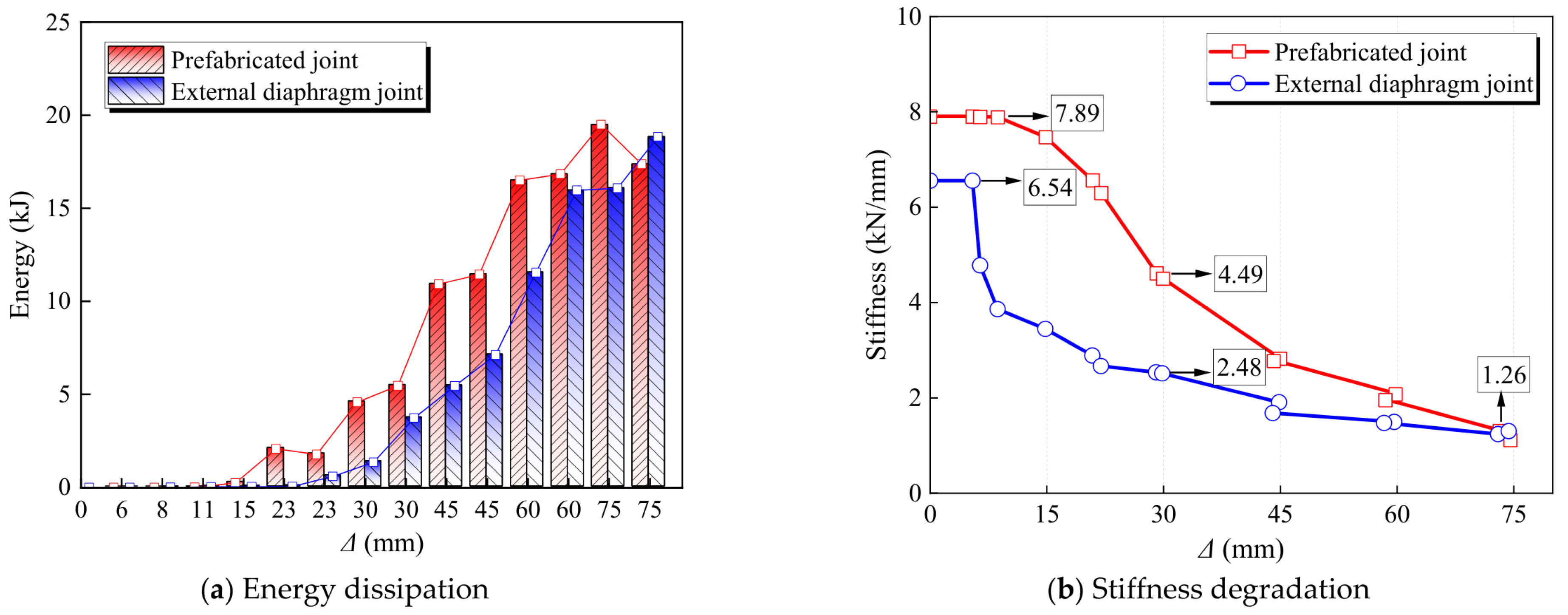
Figure 10a compares the energy dissipated per cycle at each loading level. Energy dissipation increases markedly with displacement amplitude for both joints, but the prefabricated joint dissipates more energy per cycle at most loading levels. At a displacement amplitude of 45 mm, the prefabricated joint dissipates approximately 11.0 and 11.6 kJ in the two cycles, compared with 5.1 and 6.8 kJ for the external-diaphragm joint, representing increases of approximately 116% and 71%, respectively. At 60 mm, the corresponding values are approximately 16.7 and 17.0 kJ, compared with 10.3 and 14.8 kJ, representing increases of approximately 62% and 15%, respectively. In the first cycle at 75 mm, the prefabricated joint dissipates approximately 19.7 kJ, approximately 23% more than the 16.0 kJ dissipated by the external-diaphragm joint. Energy dissipation by the prefabricated joint decreases in the second cycle at the final loading level owing to local buckling and accumulated plastic deformation in the paired channels. Summing the energy dissipated over the plotted cycles gives approximately 40% greater total energy dissipation for the prefabricated joint, indicating more effective participation of the paired channels in plastic energy dissipation.
Figure 10.
Comparison of energy dissipation and stiffness degradation between the two joints: (a) Energy dissipation; (b) Stiffness degradation.
Figure 10b compares the stiffness degradation of the two joints. The prefabricated joint has an initial stiffness of 7.89 kN/mm, approximately 20.6% higher than the 6.54 kN/mm of the external-diaphragm joint. Stiffness decreases with increasing cyclic displacement in both joints, but the external-diaphragm joint exhibits a faster initial decline, whereas degradation in the prefabricated joint is more gradual. At 30 mm, their stiffnesses are 4.49 and 2.48 kN/mm, respectively, with the prefabricated joint retaining approximately 81.0% higher stiffness. At 75 mm, its stiffness remains at 1.26 kN/mm, compared with approximately 1.05 kN/mm for the external-diaphragm joint. The proposed prefabricated joint thus localizes damage in the replaceable paired channels while providing higher initial stiffness, greater energy dissipation, and better stiffness retention under cyclic loading.
5. Parametric Analysis
5.1. Effect of Channel Thickness
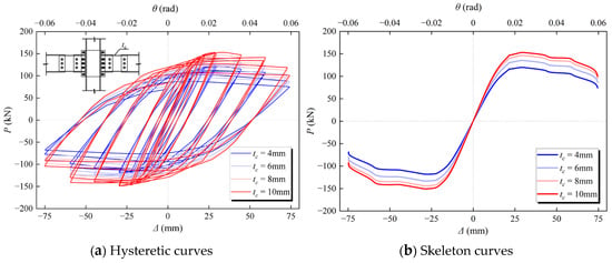
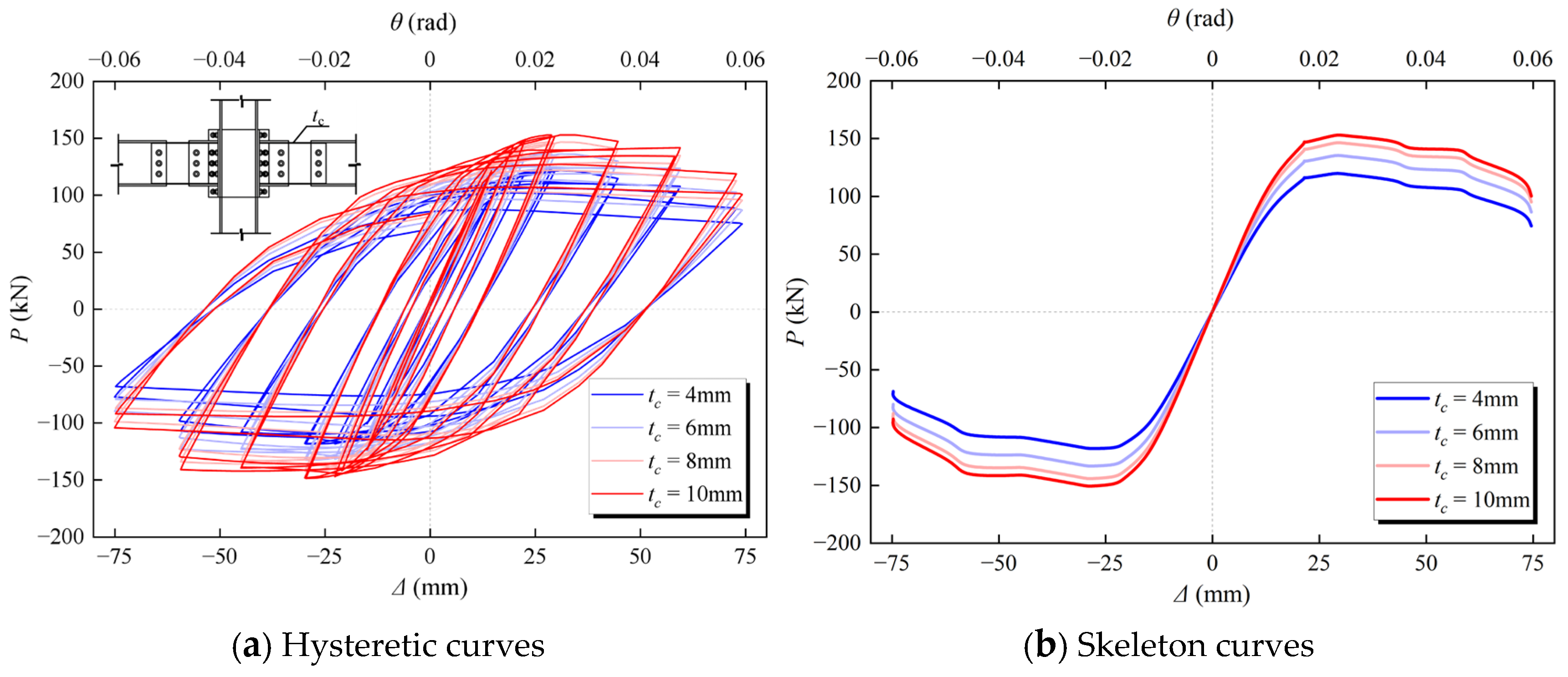
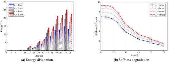
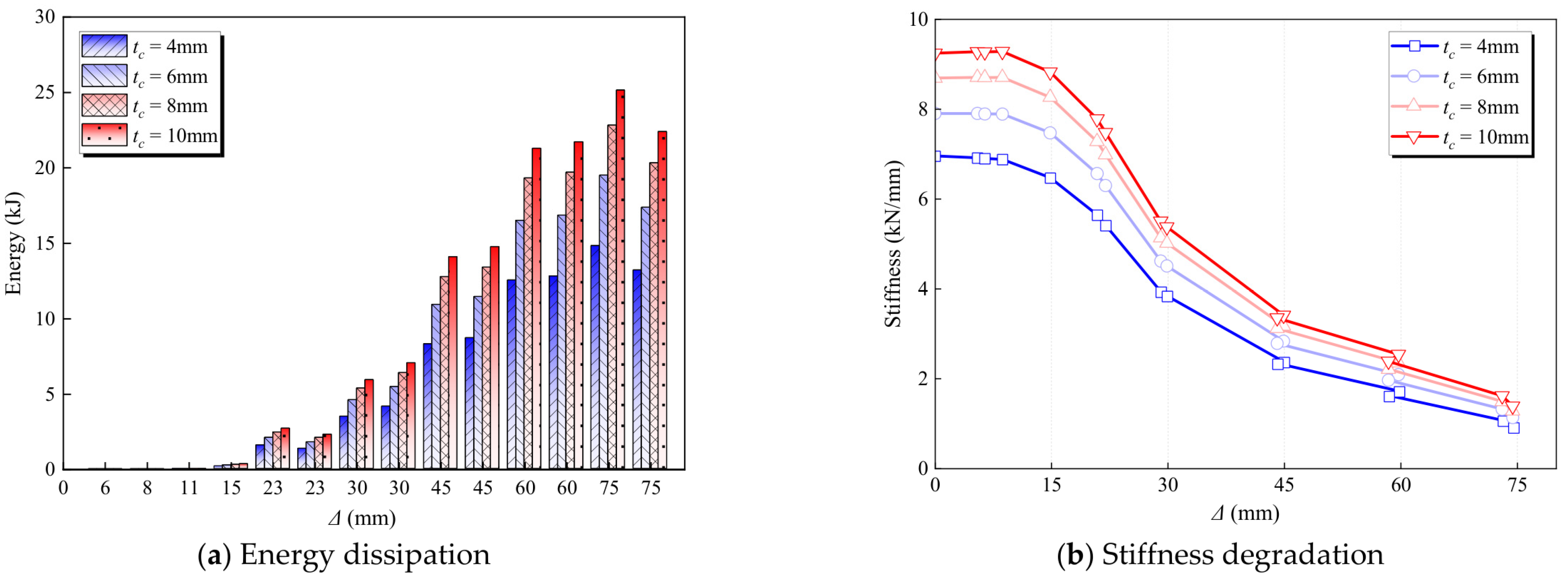
Channel thickness (tc) was set to 4, 6, 8, and 10 mm, with all other parameters held constant, to examine its effect on joint seismic performance. Figure 11 shows the hysteretic and skeleton curves, while Figure 12 presents energy dissipation and stiffness degradation. Key response parameters are summarized in Table 3.
Figure 11.
Hysteretic and skeleton curves for different channel thicknesses: (a) Hysteretic curves; (b) Skeleton curves.
Figure 12.
Energy dissipation and stiffness degradation for different channel thicknesses: (a) Energy dissipation; (b) Stiffness degradation.
Table 3.
Characteristic parameters and ductility for different channel thicknesses.
As shown in Figure 11, increasing channel thickness produces larger, fuller hysteresis loops and markedly improves load-bearing capacity. The skeleton curves indicate a pronounced effect on post-yield strength. As tc increases from 4 to 10 mm, the yield load (Py) increases from 114.00 to 139.31 kN, a gain of 22.2%, while the peak load (Pmax) increases from 119.37 to 152.40 kN, a gain of 27.7%. Increasing thickness from 6 to 8 mm raises the peak load by 8.2%, whereas a further increase to 10 mm provides only a 4.5% gain, indicating diminishing strength gains. Over the same thickness range of 4–10 mm, yield displacement decreases from 16.40 to 15.07 mm, while ultimate displacement increases from 58.43 to 63.24 mm, raising the displacement ductility factor from 3.56 to 4.20. Increasing channel thickness therefore improves both load-bearing and deformation capacities.
Figure 12a shows that channel thickness substantially affects energy dissipation. Cumulative energy dissipation (E) increases from 14.82 kJ at tc = 4 mm to 19.50, 22.82, and 25.16 kJ at 6, 8, and 10 mm, respectively. The joint with 10 mm channels dissipates approximately 69.8% more energy than that with 4 mm channels. Relative to the joint with 6 mm channels, energy dissipation increases by 17.0% and 29.0% for channel thicknesses of 8 and 10 mm, respectively.
Figure 12b shows progressive stiffness degradation with increasing cyclic displacement for all joints, but thicker channels maintain higher secant stiffness throughout loading. Initial stiffness increases from 6.95 kN/mm at tc = 4 mm to 9.24 kN/mm at tc = 10 mm, an increase of approximately 33.0%. The joint with 10 mm channels also has approximately 17.0% higher initial stiffness than that with 6 mm channels. These results indicate that increasing channel thickness improves the flexural stiffness of the connection region and slows stiffness degradation under cyclic loading. Although thicker channels improve load-bearing capacity, initial stiffness, ductility, and energy dissipation, the gains in strength and ductility diminish markedly from 8 to 10 mm, indicating diminishing benefits from increasing channel thickness alone.
5.2. Effect of Channel Length
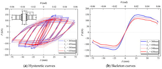
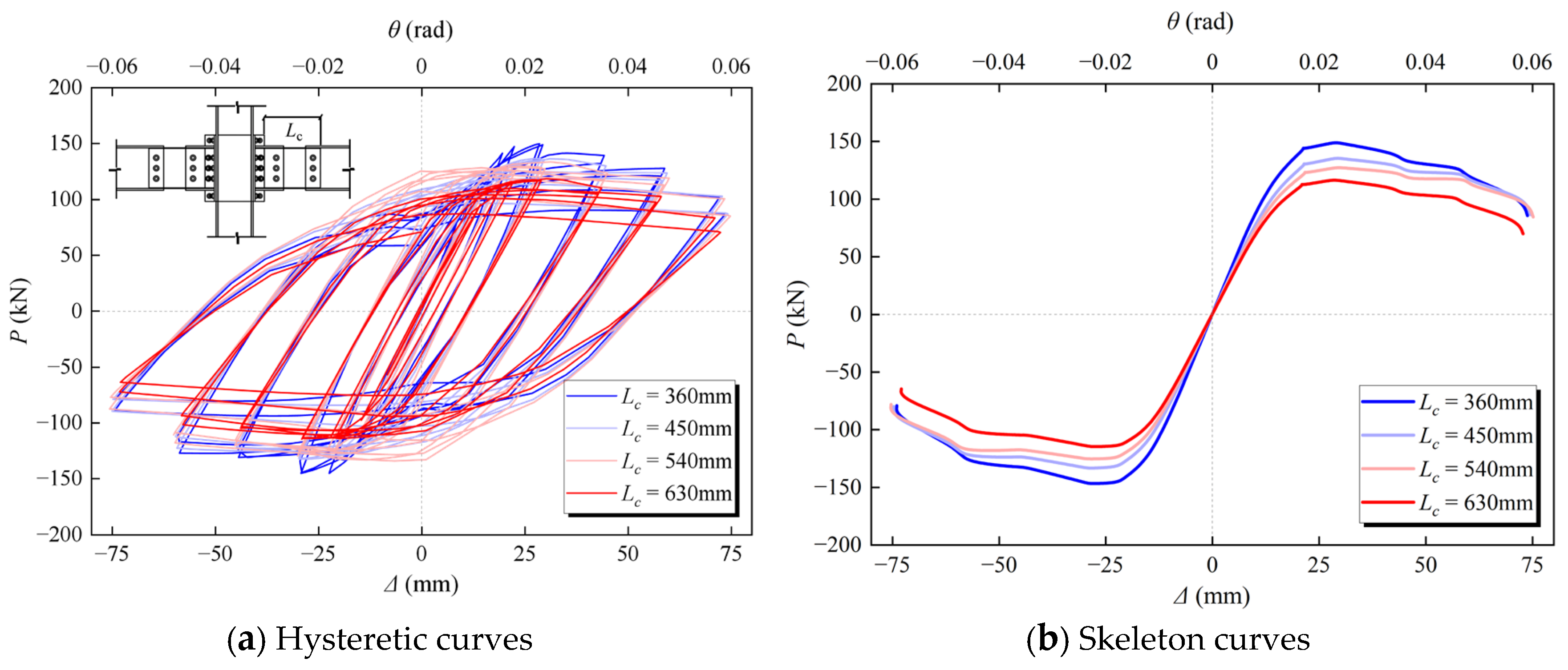
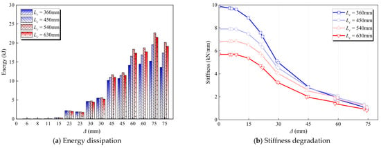
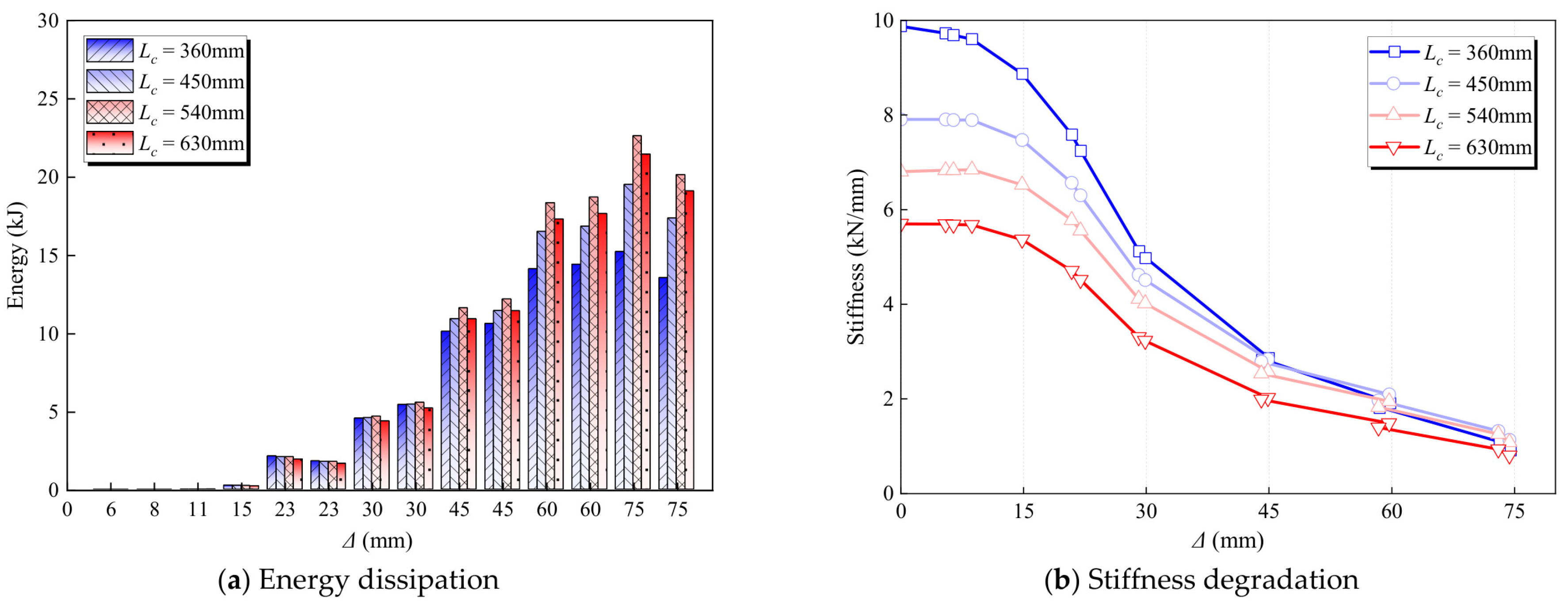
The effective energy-dissipating length of the channels (Lc) was set to 360, 450, 540, and 630 mm, with all other parameters held constant, to examine its effect on joint seismic performance. Figure 13 shows the hysteretic and skeleton curves, while Figure 14 presents energy dissipation and stiffness degradation. Key response parameters are summarized in Table 4.
Figure 13.
Hysteretic and skeleton curves for different channel lengths: (a) Hysteretic curves; (b) Skeleton curves.
Figure 14.
Energy dissipation and stiffness degradation for different channel lengths: (a) Energy dissipation; (b) Stiffness degradation.
Table 4.
Characteristic parameters and ductility for different channel lengths.
Figure 13 shows that increasing Lc expands the hysteresis loops in the displacement direction while reducing peak load. The skeleton curves indicate a pronounced influence of channel length on stiffness, strength, and deformation capacity. As Lc increases from 360 to 630 mm, the yield load (Py) decreases from 138.23 to 107.80 kN, a reduction of 22.0%, while the peak load (Pmax) decreases from 148.27 to 115.92 kN, a reduction of 21.8%. Meanwhile, ultimate displacement increases from 52.78 to 75.75 mm, a gain of 43.5%, and the displacement ductility factor increases from 3.78 to approximately 4.03. Increasing the effective energy-dissipating length therefore reduces load-bearing capacity but improves deformation capacity and ductility.
Figure 14a shows that cumulative energy dissipation initially increases with Lc and then decreases slightly. It increases from 15.21 kJ at Lc = 360 mm to 22.62 kJ at Lc = 540 mm, a gain of 48.7%. A further increase to 630 mm reduces cumulative energy dissipation to 21.45 kJ, approximately 5.2% below that at 540 mm. These results indicate that moderately increasing channel length expands the extent of plastic deformation and improves cyclic energy dissipation, but the benefit diminishes when the dissipative segment becomes too long.
Figure 14b shows progressive stiffness degradation with increasing cyclic displacement, with longer channels producing lower overall joint stiffness. Initial stiffness decreases steadily from 9.87 kN/mm at Lc = 360 mm to 7.90, 6.79, and 5.69 kN/mm at 450, 540, and 630 mm, respectively, representing a total reduction of 42.4%. Shorter channels provide higher initial stiffness and load-bearing capacity, whereas appropriately increasing the effective energy-dissipating length improves ductility and energy dissipation. Within the investigated range, Lc = 540 mm provides the highest cumulative energy dissipation while maintaining high ductility, offering a favorable balance among stiffness, strength, and energy dissipation.
5.3. Effect of Axial Compression Ratio
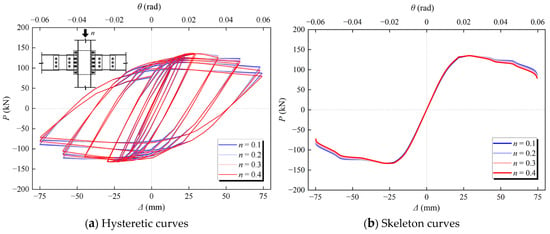
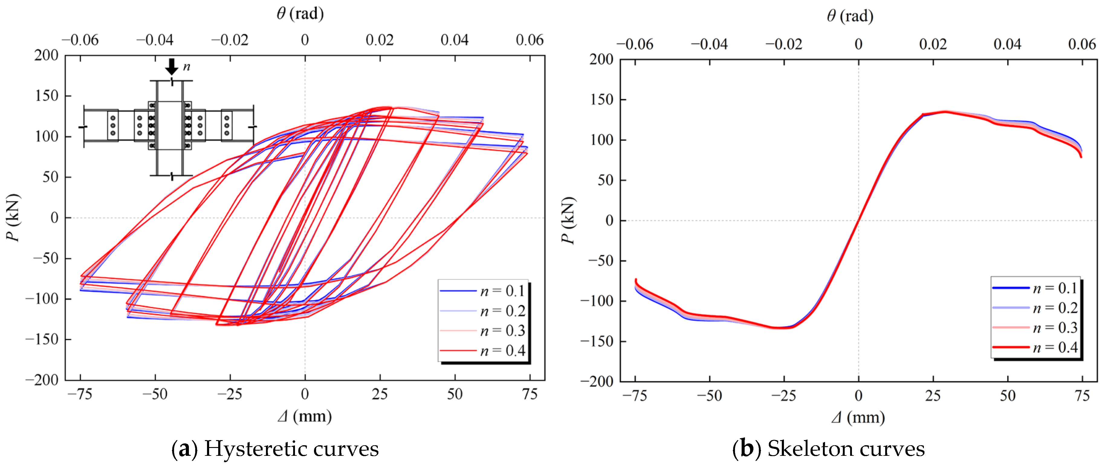
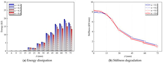
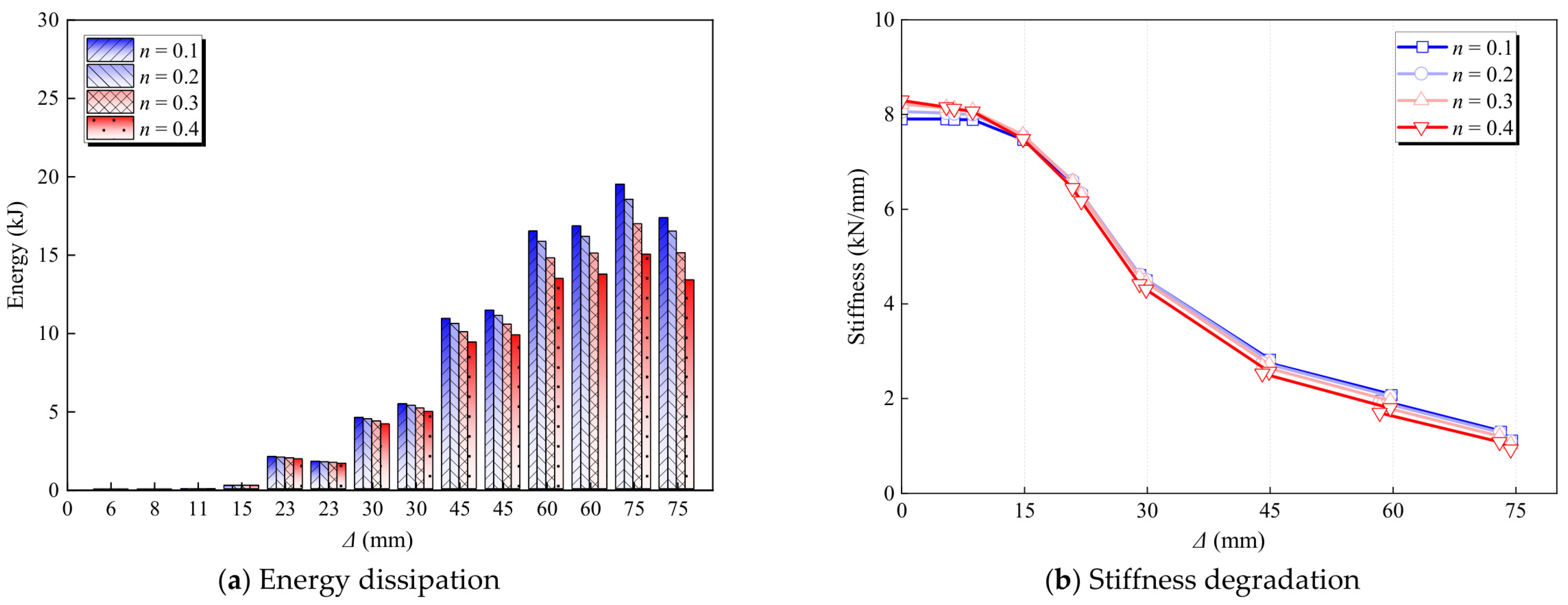
The column axial compression ratio (n) was set to 0.1, 0.2, 0.3, and 0.4, with all other parameters held constant, to examine its effect on joint seismic performance. Figure 15 shows the hysteretic and skeleton curves, while Figure 16 presents energy dissipation and stiffness degradation. Key response parameters are summarized in Table 5.
Figure 15.
Hysteretic and skeleton curves for different axial compression ratios: (a) Hysteretic curves; (b) Skeleton curves.
Figure 16.
Energy dissipation and stiffness degradation for different axial compression ratios: (a) Energy dissipation; (b) Stiffness degradation.
Table 5.
Characteristic parameters and ductility for different axial compression ratios.
Figure 15 shows similar hysteresis loop shapes for different axial compression ratios, with the skeleton curves nearly overlapping throughout most loading stages. This indicates a limited effect on load-bearing capacity. As n increases from 0.1 to 0.4, the yield load (Py) changes from 126.82 to 125.59 kN, and the peak load (Pmax) changes from 134.79 to 134.57 kN, with both changes below 1%. These results indicate that the joint’s lateral load-bearing capacity is governed primarily by the paired energy-dissipating channels and is relatively insensitive to the column axial load. In contrast, deformation capacity decreases with increasing axial compression ratio. Ultimate displacement decreases from 62.09 to 55.75 mm, a reduction of approximately 10.2%, while the ductility factor decreases from 3.87 to 3.68.
Figure 16a shows that energy dissipation per cycle increases with cyclic displacement for all joints, but higher axial compression ratios generally produce lower energy dissipation at moderate and large displacements. Cumulative energy dissipation (E) decreases steadily from 19.50 kJ at n = 0.1 to 18.53, 16.97, and 15.02 kJ at n = 0.2, 0.3, and 0.4, respectively. Increasing n from 0.1 to 0.4 reduces cumulative energy dissipation by approximately 23.0%, indicating that higher axial compression adversely affects cyclic plastic deformation and energy dissipation capacity.
Figure 16b shows that axial compression ratio has a limited effect on initial stiffness. As n increases from 0.1 to 0.4, initial stiffness increases from 7.90 to 8.29 kN/mm, a gain of approximately 4.9%. However, all joints undergo rapid stiffness degradation with increasing cyclic displacement, and the stiffness differences gradually diminish. Increasing the axial compression ratio therefore slightly increases initial stiffness and has little effect on peak load, while reducing ultimate deformation capacity, ductility, and cumulative energy dissipation. Degradation of deformation capacity and energy dissipation thus warrants particular attention at high axial compression ratios.
5.4. Effect of Slip Displacement
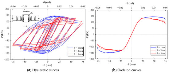
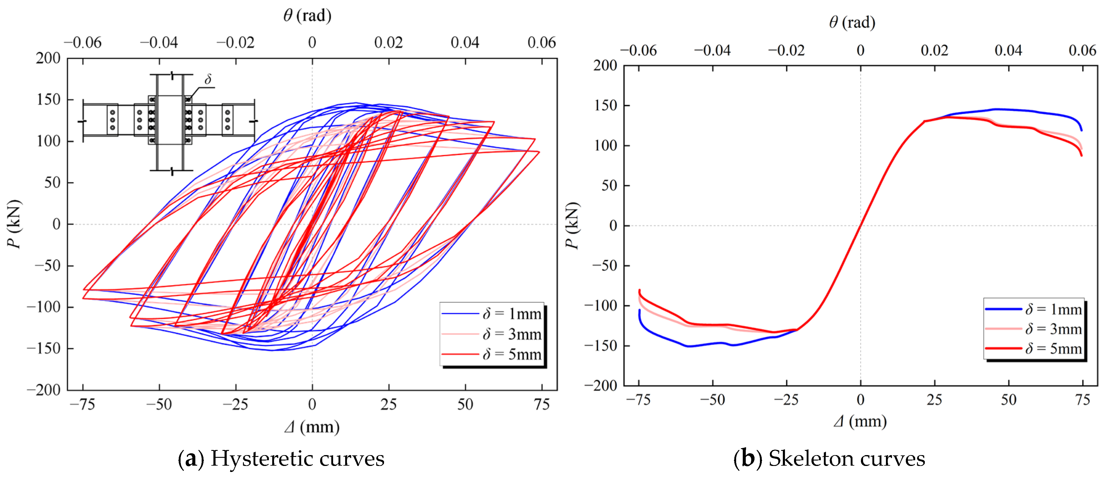
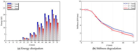
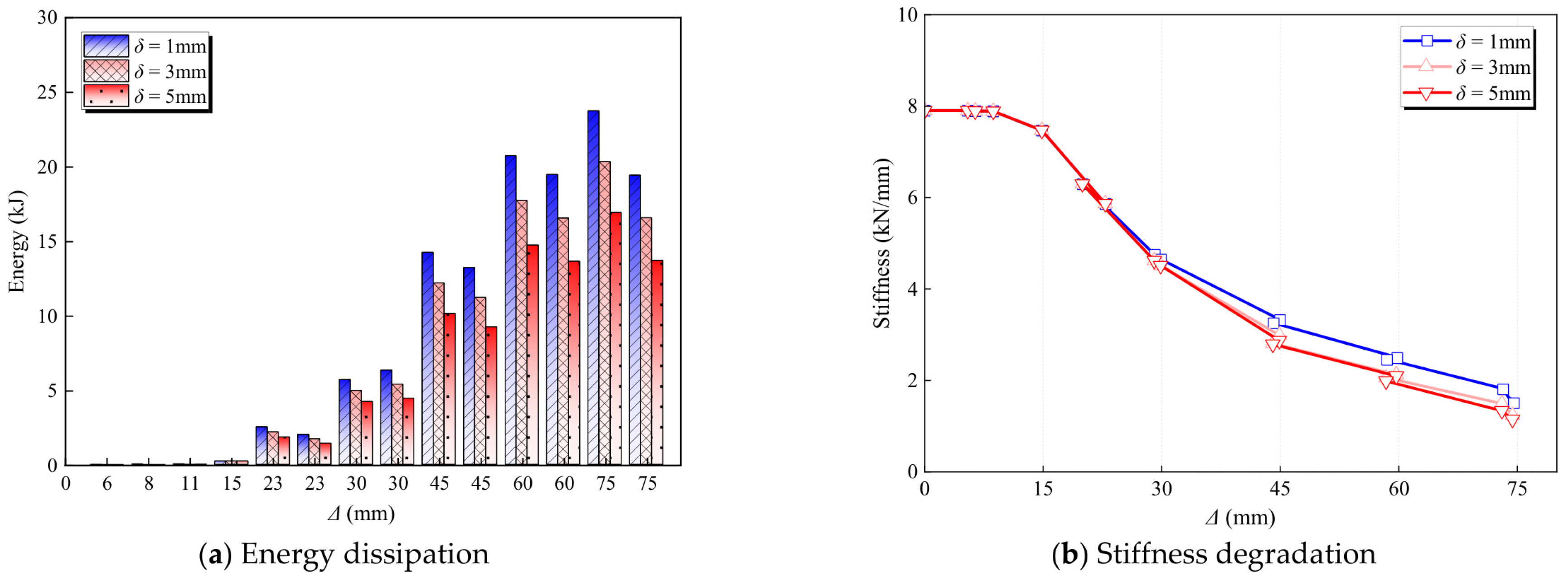
The slip displacement δ was set to 1, 3, and 5 mm to examine its influence on joint seismic performance, with the remaining parameters held constant. Figure 17 compares the hysteretic and skeleton curves, while Figure 18 presents the single-cycle energy dissipation and stiffness degradation. The characteristic response parameters are summarized in Table 6.
Figure 17.
Hysteretic and skeleton curves for different slip displacements: (a) Hysteretic curves; (b) Skeleton curves.
Figure 18.
Energy dissipation and stiffness degradation for different slip displacements: (a) Energy dissipation; (b) Stiffness degradation.
Table 6.
Characteristic parameters and ductility for different slip displacements.
As shown in Figure 17, increasing δ from 1 to 5 mm reduces the yield load (Py) from 130.62 to 123.02 kN and the peak load (Pmax) from 141.53 to 128.05 kN, corresponding to reductions of 5.8% and 9.5%, respectively. The ultimate displacement decreases from 67.06 to 57.12 mm, a reduction of 14.8%, while the displacement ductility factor decreases from 4.06 to 3.67. Larger slip displacement is therefore associated with lower load-bearing capacity and deformation capacity.
Figure 18a compares the energy dissipated per cycle at different displacement amplitudes. In the first cycle at a beam-end displacement amplitude of 75 mm, the dissipated energy is 22.43, 19.50, and 16.58 kJ for δ = 1, 3, and 5 mm, respectively. Increasing δ from 1 to 5 mm corresponds to a reduction of approximately 26.1% in the energy dissipated during this cycle. Figure 18b presents the secant stiffness degradation. The initial stiffness is approximately 7.90 kN/mm for all three cases, indicating similar responses during the initial loading stage. Stiffness subsequently decreases with increasing cyclic displacement as interface slip and inelastic deformation develop.
Increasing slip displacement has little effect on initial stiffness but reduces peak load, ultimate deformation capacity, ductility, and single-cycle energy dissipation. These trends highlight the importance of controlling interface slip to maintain the joint’s load-bearing capacity and inelastic deformation capacity under cyclic loading.
6. Yield Load Calculation
6.1. Mechanical Model and Yield Load Equation
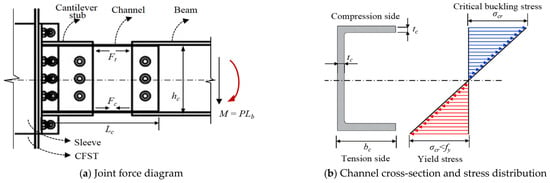
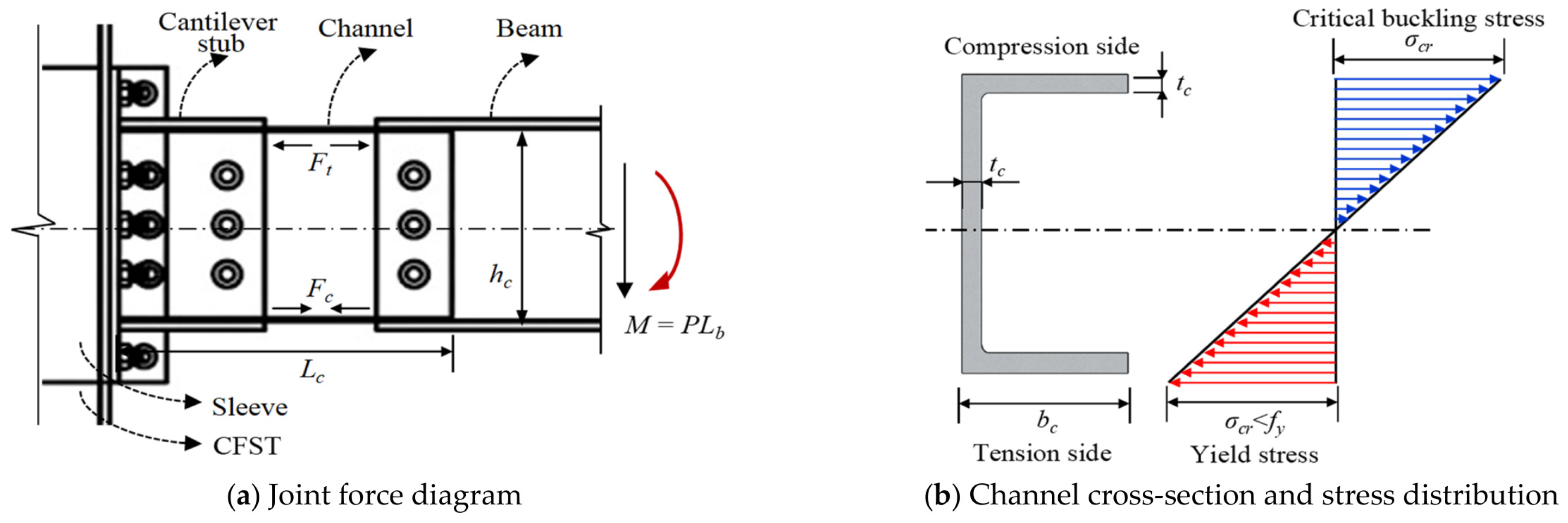
The paired channels are assumed to share the load equally, with equal flange and web thicknesses and negligible longitudinal axial force. Plane sections remain plane before yielding. Nominal section yielding occurs when the extreme-fibre longitudinal stress reaches the steel yield strength. Figure 19 shows the mechanical model.
Figure 19.
Mechanical model for yield load calculation: (a) Joint force diagram; (b) Channel cross-section and stress distribution.
For the loading direction considered, Ft and Fc denote the combined tensile and compressive forces in the upper and lower flanges of both channels, respectively:
where bc, hc, and tc are the channel flange width, overall depth, and plate thickness, respectively; d = (hc − tc)/2 is the distance from the section centroid to the flange centroid; E is the elastic modulus; and κ is the curvature. Including the web bending contribution Mw and the local flange bending contribution Mf gives:
Ft = Fc = 2bctcEκd
M = d(Ft + Fc) + Mw + Mf = EκIΣ
The combined second moment of area of the two channels about the horizontal centroidal axis is:
Setting the extreme-fibre stress Eκhc/2 equal to fy gives the yield load at one beam end:
where fy is the steel yield strength, Lb is the main beam length, and Lc is the channel length. The adopted lever arm is L = Lb + Lc − 100.
The axial compression ratio has little effect on the yield load within n = 0.10~0.40 and is therefore omitted from the equation. Interface slip is represented by the correction factor:
where aδ is a dimensionless coefficient determined from the slip-displacement series; δ0 = 3 mm. To relate nominal section yielding to the equivalent yield load identified by bilinear idealization, a reference coefficient is defined as:
Py,FE,0 and Py,sec,0 are the FE equivalent yield load and nominal section yield load of the reference joint, respectively, with tc = 6 mm, Lc = 450 mm, δ = 3 mm, and n = 0.10. Cy is determined from this joint and kept fixed for the other cases. The resulting equation is:
6.2. Comparison with FE Results
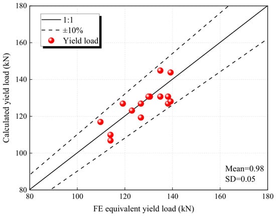
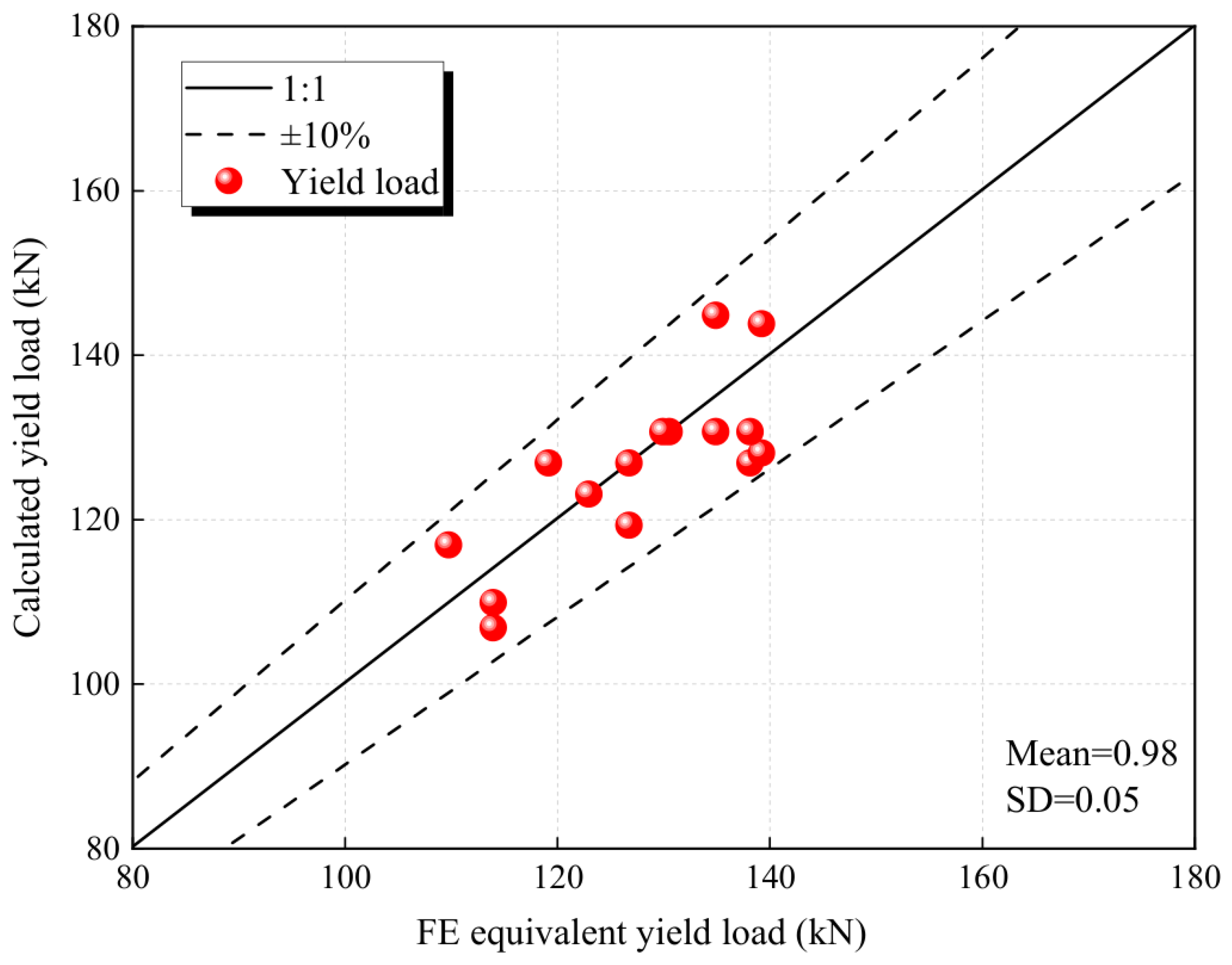
Building on the preceding parametric analysis, an expanded set of 15 finite element models was established to evaluate the proposed yield load equation. The channel thickness ranged from 4 to 10 mm, the channel length from 360 to 630 mm, the axial compression ratio from 0.1 to 0.4, and the slip displacement from 1 to 5 mm.
Figure 20 compares the calculated yield loads with the finite element results. The absolute relative errors are within 10%. The mean value is 0.98, with a standard deviation of 0.05. These results indicate that the proposed equation accurately predicts the yield load of the CFST column–steel beam joint within the investigated parameter ranges.
Figure 20.
Comparison between calculated and finite element yield loads.
7. Conclusions
This study proposed a fully bolted prefabricated CFST column–steel beam joint with replaceable double-channel energy-dissipating components. Its seismic performance was assessed through detailed finite element simulations. The main conclusions are as follows:
- (1)
- The joint provides distinct moment and shear transfer paths through the channel flanges and webs, respectively, to the cantilever stub beams, steel sleeve, and CFST column. Under cyclic loading, the paired channels yield preferentially and develop local buckling, with equivalent plastic strain and high stresses concentrated mainly in the channels and around bolt holes. Plastic damage to the main steel beam, CFST column, and steel sleeve remains limited, indicating that the joint achieves the intended damage localization and facilitates post-earthquake replacement of damaged channels.
- (2)
- Compared with the monolithic external-diaphragm joint, the proposed joint develops more extensive plastic deformation within the replaceable connection components, resulting in more distinct damage localization. Initial stiffness and total energy dissipation increase by 20.6% and approximately 40%, respectively. At a displacement of 30 mm, secant stiffness is approximately 81.0% higher, indicating improved energy dissipation and stiffness retention.
- (3)
- Increasing channel thickness improves load-bearing capacity, stiffness, and energy dissipation, although the gains diminish beyond 8 mm. Increasing channel length reduces load-bearing capacity and stiffness but improves deformation capacity, with the highest energy dissipation achieved at 540 mm. Load-bearing capacity varies by less than 1% with axial compression ratio; however, increasing the ratio from 0.1 to 0.4 reduces ultimate displacement and cumulative energy dissipation by 10.2% and 23.0%, respectively. Increasing slip displacement from 1 to 5 mm reduced peak load by 9.5% and energy dissipation in the first cycle at a 75 mm displacement amplitude by 26.1%, while initial stiffness remained approximately unchanged.
- (4)
- A simplified yield-load equation incorporating channel section properties, steel yield strength, the geometric lever arm, and correction coefficients was established. Comparison with 15 finite element results gives absolute relative errors within 10%, with a mean calculated-to-FE yield-load ratio of 0.99 and a standard deviation of 0.05. The equation provides reasonable predictions within the investigated parameter ranges.
- (5)
- Within the investigated joint dimensions and parameter ranges, a channel thickness of 8 mm is recommended. A channel length of 540 mm is preferred when prioritizing energy dissipation and deformation capacity, whereas 450 mm is preferred when prioritizing strength and initial stiffness. An axial compression ratio of 0.1–0.2 is recommended.
The present findings are limited to the investigated square CFST column section, and application to larger or circular column sections requires corresponding modifications to the sleeve and connection details and further validation. In addition, post-earthquake repair of the damaged concrete core and replacement of the CFST column were not investigated in this study.
Author Contributions
Y.W. (Yuhan Wang): Writing—Original Draft, Validation, Software, Methodology, Investigation, Formal Analysis, and Data Curation. G.Z.: Visualization, Writing—Original Draft, and Writing—Review and Editing. Y.T.: Resources and Writing—Review and Editing. Y.W. (Yanjie Wang): Conceptualization, Methodology, and Supervision. All authors have read and agreed to the published version of the manuscript.
Funding
This study was not supported by any specific grant from funding agencies in the public, commercial, or not-for-profit sectors.
Data Availability Statement
The data that support the findings of this study are available from the corresponding authors upon reasonable request.
Conflicts of Interest
The authors declare that they have no known competing financial interests or personal relationships that could have appeared to influence the work reported in this paper.
References
- Zhang, Q.; Alam, M.S. State-of-the-art review of seismic-resistant precast bridge columns. J. Bridge Eng. 2020, 25, 03120001. [Google Scholar] [CrossRef] [Scilit]
- Xu, P.Z.; Wang, Z.A.; Mou, B.; Gao, D. Seismic performance of external rib stiffened CFST column to steel beam joints. J. Constr. Steel Res. 2022, 190, 107126. [Google Scholar]
- Lin, Y.; Ye, Q.X.; Wang, Y.Q.; Shu, C.; Zhang, F.; Zhang, Y.; Zhao, Y.; Cao, H. Seismic performance of narrow section CFST column-to-steel beam through-diaphragm bolted-welded hybrid joints. Eng. Struct. 2023, 285, 116045. [Google Scholar]
- Zhu, W.Q.; Feng, C.R.; Liu, Y.J.; Yan, B. Seismic performance of concrete-filled square steel tube column connections with and without PBL. Structures 2022, 46, 1778–1793. [Google Scholar]
- Mohseni, M.; Ghassemieh, M.; Mirghaderi, R. Mechanical behavior of I-beam-to-square CFST column joints using external diaphragm and side plate connections. Eng. Struct. 2025, 327, 119582. [Google Scholar]
- Thai, H.T. Beam-to-CFST column joints in steel-concrete composite buildings: A comprehensive review. Structures 2024, 68, 107123. [Google Scholar] [CrossRef] [Scilit]
- Vulcu, C.; Stratan, A.; Ciutina, A.; Dubina, D. Beam-to-CFT high-strength joints with external diaphragm. II: Numerical simulation of joint behavior. J. Struct. Eng. 2017, 143, 04017002. [Google Scholar] [CrossRef] [Scilit]
- Rong, B.; Li, H.; Zhang, R. Experimental and numerical investigations on seismic performance of CFST frame with external diaphragm joint. J. Constr. Steel Res. 2021, 184, 106791. [Google Scholar]
- Han, L.H.; Li, W. Seismic performance of CFST column to steel beam joint with RC slab: Experiments. J. Constr. Steel Res. 2010, 66, 1374–1386. [Google Scholar] [CrossRef] [Scilit]
- Zhang, A.L.; Li, C.H.; Liu, X.C.; Chen, X.S. Seismic performance of joint for H-beam to CFST column with field-bolted flange-splicing. J. Constr. Steel Res. 2022, 196, 107375. [Google Scholar] [CrossRef] [Scilit]
- Fan, J.C.; Zhao, J.H.; Zhu, Q.; Ni, Z.Y.; Liu, J.Y. Seismic behavior and analytical model for a fully bolted joint between CFDST columns and steel beams. Structures 2022, 42, 515–530. [Google Scholar] [CrossRef] [Scilit]
- Chu, Y.P.; Zhong, Y.; Luo, P.; Chen, X.Q.; Xia, H. Experimental study on the seismic performance of the new fully-bolted beam-column joint. J. Constr. Steel Res. 2022, 199, 107619. [Google Scholar] [CrossRef] [Scilit]
- Zhang, Z.; Weng, M.; Wang, X.; Li, X. Experimental study on seismic performance of prefabricated fully-bolted exterior diaphragm joint for CFSST. J. Constr. Steel Res. 2024, 222, 108995. [Google Scholar] [CrossRef] [Scilit]
- He, Y.; Zhao, Y.G.; Lin, S.; Zhang, Z. Prefabricated bolted PEC beam-to-CFST column joints: Development and its seismic behavior. Eng. Struct. 2024, 314, 118442. [Google Scholar] [CrossRef] [Scilit]
- Ding, F.; Zhang, S.; Pan, Z.; Lei, J.; Wang, L.; Duan, L. Seismic performance of square concrete-filled steel tubular column–composite beam single-side bolted joints: An experimental and numerical study. Eng. Struct. 2025, 322, 119035. [Google Scholar] [CrossRef] [Scilit]
- He, X.Z.; Ke, K.; Guo, L.H.; Yam, M.C.H.; Wang, Z.H. A replaceable fuse steel-concrete composite connection: Force transfer mechanism and design considerations. J. Constr. Steel Res. 2021, 183, 106760. [Google Scholar] [CrossRef] [Scilit]
- Men, J.J.; Li, T.; Zhou, Q.; Zhang, H.H.; Huang, C.H. Structural fuse performance and earthquake-resilient performance of beam-column joints with replaceable T-stub. J. Constr. Steel Res. 2023, 206, 107943. [Google Scholar] [CrossRef] [Scilit]
- Zheng, H.W.; Cui, G.Z.; Kishiki, S. Cyclic elasto-plastic behaviour of replaceable ductile Split-T located at the bottom beam flange. Eng. Struct. 2024, 303, 117506. [Google Scholar] [CrossRef] [Scilit]
- Jiang, Z.Q.; Yan, T.; Zhang, A.L.; Yang, X.F.; Yu, C.; Li, R. Experimental study of plate-buckling type earthquake-resilient prefabricated steel beam-column joints with replaceable double flange cover plates. Structures 2023, 50, 1100–1113. [Google Scholar] [CrossRef] [Scilit]
- Feng, Y.L.; Li, C.N.; Wei, M.T.; Zhang, Z.; Chong, X.; Jiang, Q.; Wen, H. Experimental investigations of beam-column joints with replaceable BRFCPs using sliding restraint plates. Structures 2024, 60, 105807. [Google Scholar] [CrossRef] [Scilit]
- Feng, Y.; Zhu, Y.; Jiang, Q.; Chong, X.; Liu, Y.; Huang, J. Quasi-static and fatigue testing of earthquake-resilient steel joints with replaceable buckling-restrained links. Structures 2021, 29, 1998–2016. [Google Scholar] [CrossRef] [Scilit]
- He, X.Z.; Chen, Y.Y.; Ke, K.; Shao, T.F.; Yam, M.C.H. Development of a connection equipped with fuse angles for steel moment resisting frames. Eng. Struct. 2022, 265, 114503. [Google Scholar] [CrossRef] [Scilit]
- Li, F.Y.; Du, Y.F.; Hong, N.; Li, H.; Chi, P.H. Seismic performance of prefabricated replaceable graded-yielding energy-dissipating connectors. Eng. Struct. 2023, 297, 116962. [Google Scholar] [CrossRef] [Scilit]
- Du, Y.F.; Li, F.Y.; Li, H.; Hong, N.; Chi, P.H. Seismic behavior and resilience assessment of prefabricated beam-column joint with replaceable graded-yielding energy-dissipating connectors. Eng. Struct. 2024, 319, 118814. [Google Scholar] [CrossRef] [Scilit]
- Yang, C.T.; Xie, L.L.; Li, A.Q.; Wang, X.Y. Development of a double-stage-yield dissipative beam-to-column joint: Experimental study and application for structural response control. Soil Dyn. Earthq. Eng. 2023, 171, 107997. [Google Scholar] [CrossRef] [Scilit]
- Latour, M.; D’aNiello, M.; Zimbru, M.; Rizzano, G.; Piluso, V.; Landolfo, R. Removable friction dampers for low-damage steel beam-to-column joints. Soil Dyn. Earthq. Eng. 2018, 115, 66–81. [Google Scholar] [CrossRef] [Scilit]
- Nastri, E.; Latour, M.; Pecorari, O.; Piluso, V. Experimental lap-shear tests on friction dampers with single and double slotted holes. Eng. Struct. 2024, 308, 117968. [Google Scholar] [CrossRef] [Scilit]
- Zhang, Q.; Men, J.J.; Wang, J.C.; He, P.J.; Huang, C.H.; Li, J.F. Seismic performance evaluation of a replaceable steel beam with slotted bolted connections. J. Constr. Steel Res. 2022, 198, 107553. [Google Scholar] [CrossRef] [Scilit]
- Kanyilmaz, A.; Muhaxheri, M.; Castiglioni, C.A. Influence of repairable bolted dissipative beam splices (structural fuses) on reducing the seismic vulnerability of steel-concrete composite frames. Soil Dyn. Earthq. Eng. 2019, 119, 235–249. [Google Scholar] [CrossRef] [Scilit]
- Mou, B.; Yan, X.C.; Bi, K.M.; Pan, W.; He, C. Self-centering concrete-filled steel tubular column-steel beam joint: Experiment and numerical modeling. Eng. Struct. 2024, 312, 118272. [Google Scholar] [CrossRef] [Scilit]
- Yang, Y.; Yang, P.; Tuo, X.; Bursi, O.S.; Shen, P. Experimental study on a self-centering RCS interior joint endowed with replaceable dampers. J. Constr. Steel Res. 2022, 196, 107390. [Google Scholar] [CrossRef] [Scilit]
- Tong, C.; Wu, J.; Li, C.Y. A novel precast concrete beam-to-column connection with replaceable energy-dissipation connector: Experimental investigation and theoretical analysis. Eng. Struct. 2021, 245, 112857. [Google Scholar]
- Wang, F.M.; Zhou, Z.X.; He, Z.P.; Ren, Y.C.; Xie, W. Seismic performance of steel frame joint with dumbbell-type replaceable energy-consuming beam sections. J. Eng. Appl. Sci. 2025, 72, 79. [Google Scholar] [CrossRef] [Scilit]
- Li, G.; Ma, Y.; Li, X.; Han, Z.; Lin, R. Experimental study on seismic and earthquake-resilient performance of embedded CFRP circular tube CFSST column–H-beam joint with energy-dissipation angle steel. J. Build. Eng. 2026, 121, 115631. [Google Scholar] [CrossRef] [Scilit]
- Men, J.; Xiong, L.; Wang, J.; Zhang, Q. Experimental and numerical study on the behavior of novel multi-segment replaceable steel shear links. J. Constr. Steel Res. 2022, 194, 107314. [Google Scholar] [CrossRef] [Scilit]
- Zhou, Y.; He, H.; Cao, S.; Zhu, T.; Fei, Z.; Wu, M.; Tian, X. Seismic performance and buckling length calculation method of concrete-filled steel tube columns. Buildings 2025, 15, 4007. [Google Scholar] [CrossRef] [Scilit]
- He, H.; Zhou, Y.; Xi, W.; Wu, M.; Zhu, T.; Cao, S.; Deng, Y.; Fei, Z. Seismic performance of steel beam-to-column joints with SMA bolts and replaceable ring dampers. Buildings 2026, 16, 1209. [Google Scholar] [CrossRef] [Scilit]
- GB 50011-2010; Code for Seismic Design of Buildings. China Architecture & Building Press: Beijing, China, 2016. (In Chinese)
- GB 50017-2017; Standard for Design of Steel Structures. China Architecture & Building Press: Beijing, China, 2017. (In Chinese)
- GB 50936-2014; Technical Code for Concrete-Filled Steel Tubular Structures. China Architecture & Building Press: Beijing, China, 2014. (In Chinese)
- AISC 341-16; Seismic Provisions for Structural Steel Buildings. American Institute of Steel Construction: Chicago, IL, USA, 2016.
- Zhang, Y.; Jia, H.; Li, Y.; Demoha, K. Experiments on cyclic performance of external diaphragm joints between CFDST columns and steel beams. Bull. Earthq. Eng. 2020, 18, 3843–3861. [Google Scholar] [CrossRef] [Scilit]
- Wang, X.J.; Wang, Y.Q. An, Experimental study on seismic behavior of prefabricated beam-to-column high-strength bolted joint with external diaphragms. China Civ. Eng. J. 2020, 53, 53–63+78. (In Chinese) [Google Scholar]

Disclaimer/Publisher’s Note: The statements, opinions and data contained in all publications are solely those of the individual author(s) and contributor(s) and not of MDPI and/or the editor(s). MDPI and/or the editor(s) disclaim responsibility for any injury to people or property resulting from any ideas, methods, instructions or products referred to in the content. |
© 2026 by the authors. Licensee MDPI, Basel, Switzerland. This article is an open access article distributed under the terms and conditions of the Creative Commons Attribution (CC BY) license.