


Abstract
Aiming at the wind-blown snow disasters plaguing tunnel portals along the China-Tajikistan Highway Phase II Project, this study optimizes the protective parameters of wind deflectors through numerical simulation to improve the disaster prevention efficiency of tunnel portals in alpine mountainous areas. Three core control parameters of wind deflectors, namely horizontal distance from the tunnel portal (L), plate inclination angle (β), and top installation height (h), were selected as the research objects. Single-factor numerical simulation scenarios were designed for each parameter, and an L9(33) orthogonal test was further adopted to formulate 9 groups of multi-parameter combination scenarios, with the snow phase volume fraction at 35 m on the leeward side of the tunnel portal set as the core evaluation index. A computational fluid dynamics (CFD) model was established to systematically investigate the influence laws of each parameter on the wind field structure and snow drift deposition characteristics at tunnel portals and clarify the flow field response rules under different parameter configurations. Single-factor simulation results show that the wind deflector exerts distinct regulatory effects on the wind-snow flow field with different parameter settings: when L = 6 m, the disturbance zone of the wind deflector precisely covers the main wind flow development area in front of the tunnel portal, which effectively lifts the main incoming flow path, compresses the recirculation zone (length reduced from 45.8 m to 22.3 m), and reduces the settlement of snow particles, achieving the optimal comprehensive prevention effect; when β = 60°, the leeward wind speed at the tunnel portal is significantly increased to 10–12 m/s (from below 10 m/s), which effectively promotes the transport of snow particles and mitigates the accumulation risk, being the optimal inclination angle; when h = 2 m, the wind speed on both the windward and leeward sides of the tunnel portal is significantly improved, and the snow accumulation risk at the portal reaches the minimum. Orthogonal test results further quantify the influence degree of each parameter on the snow prevention effect, revealing that the horizontal distance from the tunnel portal is the most significant influencing factor. The optimal parameter combination of the wind deflector is determined as L = 6 m, β = 60°, and h = 2 m. Under this optimal combination, the snow phase volume fraction at 35 m on the leeward side of the tunnel portal is 0.0505, a 12.3% reduction compared with the non-deflector condition; the high-concentration snow accumulation zone is shifted 25 m leeward, and the high-value snow phase volume fraction area (>0.06) disappears completely, which can effectively alleviate the adverse impact of wind-blown snow disasters on the normal operation of tunnel portals. The research results reveal the regulation mechanism of wind deflector parameters on the wind-snow flow field at alpine tunnel portals and determine the optimal protective parameter combination, which can provide important theoretical reference and technical support for the prevention and control of wind-blown snow disasters at tunnel portals in similar alpine mountainous areas.
1. Introduction
With the advancement of the “Belt and Road” Initiative, the scale of tunnel engineering projects constructed by China in the high-altitude, frigid mountainous regions of Central Asia has expanded significantly [1,2]. However, the complex terrain and extreme wind-snow conditions in these regions lead to frequent wind-blown snow disasters at tunnel portals, which seriously threaten the safety of engineering construction and operational efficiency [3,4]. Therefore, clarifying the formation mechanism of wind-blown snow disasters at tunnel portals and implementing protective measures to minimize their impacts on highway tunnel construction and operation have become critical issues urgently requiring resolution for the construction and safe operation of tunnel projects in Central Asian mountainous areas [5,6].
Current research on wind-blown snow disaster prevention is primarily divided into active and passive protection strategies [7,8,9]. Active protection mainly focuses on the design of tunnels and roads themselves: it enhances road adaptability to wind-blown snow disasters by optimizing the cross-sectional structure of embankments or cuttings, rationally arranging route directions, adjusting the location of auxiliary facilities, and controlling embankment heights or cutting depths [10,11,12]. Passive protection adopts a “blocking-guiding” strategy to control snow particle migration and deposition through the installation of facilities such as snow fences, snow retaining walls, snow protection forests, or wind deflectors, thereby achieving disaster prevention and mitigation [13,14]. Additionally, it alters snow spatial distribution through artificial intervention in surrounding terrain and landforms—for example, excavating snow storage platforms and constructing snow storage ditches near tunnel portals-to reduce disaster occurrence probability [15,16].
Shaw [17] pointed out that snow fences with a longitudinal layout exhibit an “end effect” in their protective performance: snow accumulation is greater in the middle area, while snow-retaining capacity is significantly reduced near both ends. To effectively cover the target road section, Shaw recommended that the length of snow fences should extend more than 30 m beyond both ends of the road. The Wyoming Highway Commission [18] identified snow fences as the most economical measure for controlling wind-blown snow on highways. Their function is to block or attenuate wind-snow flow via physical barriers, thereby preventing snow particle deposition on road surfaces. However, unreasonable design parameters or installation locations may instead exacerbate snow accumulation in driving lanes. Key parameters influencing their snow-retaining performance include dominant wind direction, fence length and height, porosity, and bottom gap. Tabler [19] demonstrated through research that snow fences can effectively reduce wind speed, alter wind field structure, weaken the wind’s snow particle transport capacity, and thus promote the settlement of saltating and creeping snow particles. Notably, the bottom gap—defined as the vertical distance between the lower edge of the fence and the ground—also exerts a significant impact on wind field distribution. Basnet [20] found via field observations that fences with 30% porosity achieve optimal performance in controlling the length of leeward snow accumulation.
As an active structure for diverting wind-snow flow, wind deflectors are typically installed on the windward side of roads. They reduce the retention and deposition of snow particles on road surfaces by altering airflow paths and increasing local wind speeds. Wang et al. [21] confirmed that natural wind deflectors exhibit a certain effect in controlling highway wind-blown snow and proposed structural improvement suggestions to address issues such as insufficient snow removal efficiency and susceptibility to structural damage in specific areas. Design must fully account for regional wind-snow intensity and topographical characteristics. Additionally, snow fence porosity significantly impacts snow-retaining capacity, and design parameters should be adjusted to local conditions. During the road engineering design phase, Yang et al. [22] emphasized that the impact of wind-blown snow on roads can be mitigated at the source by optimizing route horizontal alignment and vertical section parameters—for example, controlling subgrade filling height, adopting separated cross-sections, or adjusting slope ratios can all enhance road resistance to wind-blown snow.
Constantinescu et al. [23] pointed out that snow fences with 50% porosity achieve the most significant snow-retaining effect under various working conditions. However, in road sections with limited space, low-porosity fence designs can not only maintain a certain protective effect but also effectively reduce leeward snow accumulation. Du et al. [24] argued that to maximize snow fence effectiveness, their layout direction should be perpendicular to the dominant wind direction, thereby enhancing snow particle blocking capacity. When leeward snow accumulation on fences reaches a saturated state, their snow storage capacity hits an upper limit—a phenomenon termed “balanced drift”. Wu [25] proposed that for areas with stable dominant wind directions, installing wing-type snow retaining walls on one side of the road can improve protective performance.
Li [26] used numerical simulation methods to analyze the influence of three wind deflector configurations (forward-inclined, backward-inclined, and vertical) on snow distribution in cuttings. Results indicate that wind deflectors tend to induce primary and secondary vortex structures inside cuttings, leading to significant spatial differences in snow particle concentration distribution; among these, the 45° forward-inclined wind deflector performs optimally in typical cutting cross-sections, effectively shortening the length of snow deposition zones. Regarding shed tunnel protection, Ma et al. [27] conducted wind tunnel tests using 1:60 scale shed tunnel models fabricated via 3D printing, and compared the simulation performance of materials including refined salt, fine sand, and sawdust. They found that sawdust most closely replicates actual wind-blown snow characteristics for snow particle simulation. Chen et al. [28] demonstrated through quantitative analysis that widening and deepening snow storage platforms help enhance snow particle deposition capacity. Their research indicates that protective effects against wind-blown snow are optimal when snow storage platforms exceed 5 m in width and are no less than 2 m in depth.
From existing research on protective measures for wind-blown snow, numerous studies have focused on macro-scale snow-retaining projects; however, there is a lack of quantitative research on the specific configuration parameters of various protective measures, and a relatively comprehensive response strategy system for wind-blown snow prevention and control has not yet been established. Most existing studies on wind deflectors only involve qualitative analysis of structural forms or single-parameter influence, failing to clarify the coupling effect of multiple key parameters (horizontal distance from tunnel portal, plate inclination angle, top installation height) and identify the optimal parameter combination. Moreover, few studies target the extreme wind-snow environment of alpine mountain tunnel portals in Central Asia, resulting in a lack of targeted technical support for engineering practice in such regions.
This study aims to fill these research gaps with the following novelties: first, it takes the China-Tajikistan Highway Phase II Project tunnel portals, which suffer from severe wind-blown snow disasters, as the engineering background, and focuses on the quantitative optimization of wind deflector key parameters, making the research results more targeted to practical engineering needs. Second, by combining single-factor sensitivity analysis and L9(33) orthogonal test design, the study systematically explores the individual and coupling effects of three core parameters on wind field structure and snow deposition, overcoming the limitations of single-parameter analysis in previous studies. Third, it takes the snow phase volume fraction at 35 m on the leeward side of the tunnel portal as the core evaluation index, supplemented by quantitative indicators such as recirculation zone length and area, wind speed enhancement amplitude, to construct a comprehensive evaluation system for wind deflector prevention and control effects, improving the reliability of optimization results.
The overall structure of this paper is arranged as follows: Section 1 serves as an introduction, outlining the research background, current domestic and international research status, and the significance of the study. Section 2 introduces the project overview, including the basic information of the China-Tajikistan Highway Phase II Project section and the characteristics of the wind-snow environment in the study area. Section 3 details the structural design of wind deflectors, parameter selection, numerical model establishment, solution parameter settings, and grid independence verification, and conducts single-factor analysis on the three key parameters to clarify their influence laws. Section 4 designs orthogonal tests to explore the optimal combination of wind deflector parameters and verifies its prevention and control effects. Section 5 summarizes the main conclusions of the study, analyzes the limitations of the research, and proposes future research directions. This structural arrangement ensures a logical progression from background introduction to method establishment, result analysis, and conclusion summary, providing a clear research framework for the optimization of wind and snow protection at tunnel portals in alpine mountains.
2. Project Overview
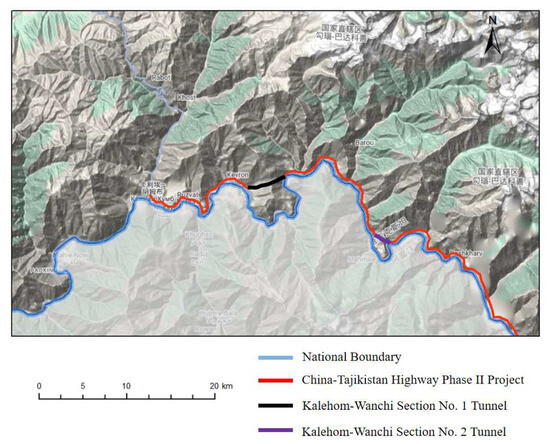
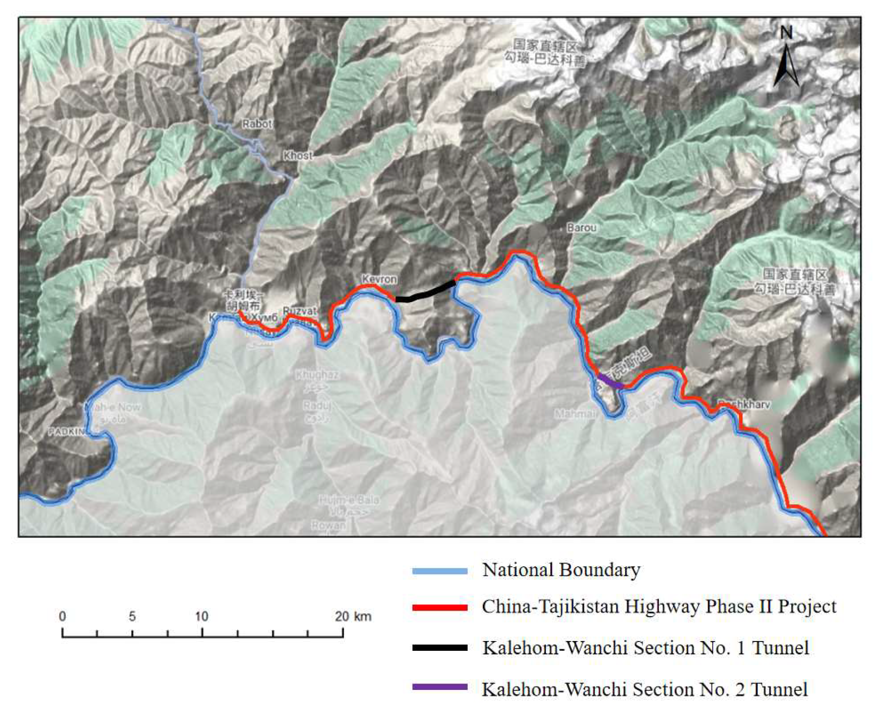
The key section of the China-Tajikistan Highway Phase II Project in Tajikistan has a total length of approximately 92.3 km. It starts from Kalaihom District, ends at the border of Rushan District, and is reconstructed and expanded along the existing China-Tajikistan Highway. The project comprises the construction of 2 tunnels (Kalaihom-Wanchi Section No. 1 Tunnel and Kalaihom-Wanchi Section No. 2 Tunnel), an open-cut tunnel with a total length of 540.64 m, 16 bridge projects in total, and the subgrade and pavement works for the entire line. Among these, Kalaihom-Wanchi Section No. 1 Tunnel has a total length of 3388 m, and Kalaihom-Wanchi Section No. 2 Tunnel has a total length of 1805 m, as presented in Figure 1.
Figure 1.
Distribution map of tunnels on the China-Tajikistan Highway Phase II Project.
The tunnel site is situated in an alpine landform, with the tunnel body traversing mountain ridges. The overall terrain is high in the middle and low at both ends, with ground elevations ranging from 1300 to 2200 m and undulating terrain. The tunnel entrances and exits are steep, with slopes exceeding 40°. The project area features typical plateau frigid climate characteristics: from October each year to April or even May of the following year, influenced by the combined effects of the westerly belt and the southward movement of polar cold air, it enters a long snow season, with the cumulative number of snowfall days reaching 150 to 180 days and the maximum snow depth up to 1.8 m. Tunnel construction is confronted with multiple natural constraints: first, the portal area is affected by the “Venturi effect”, with the average winter wind speed reaching 6 to 8 m/s; frequent wind-blown snow leads to snow accumulation at the portals, and a single average snowfall event can form a 0.3 to 0.5 m thick snow layer, which severely impedes construction access.
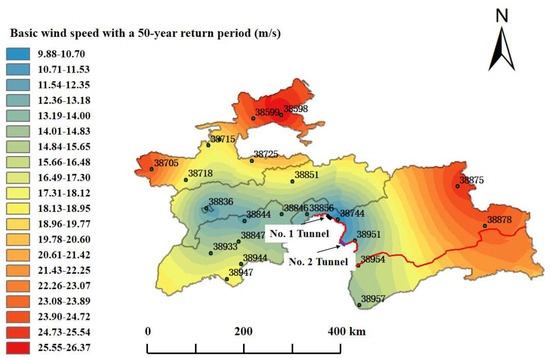
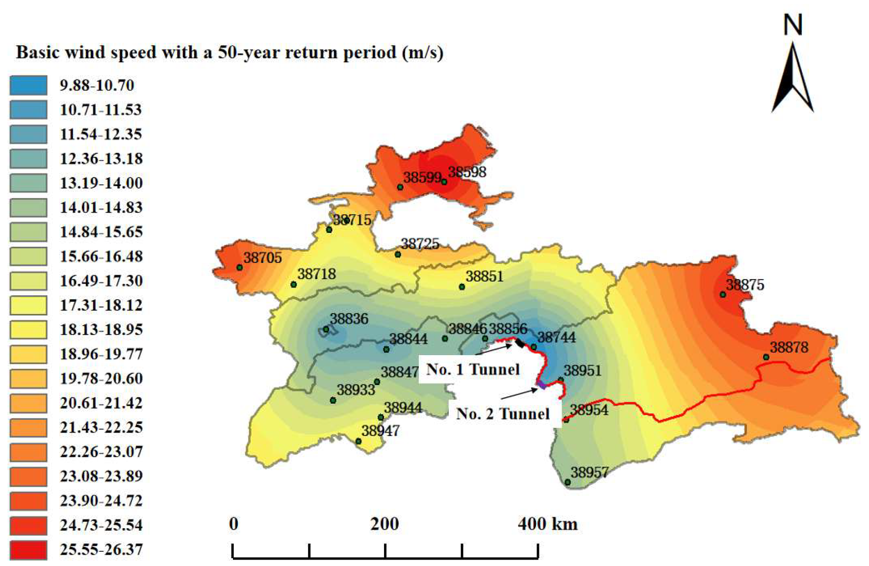
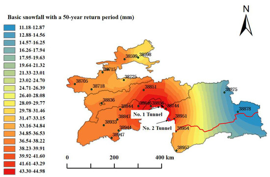
Based on meteorological data from 22 meteorological stations in Tajikistan spanning 1981 to 2021, the winter wind speed grades, snowfall grades, and wind distribution within 6 days after heavy snowfall events were calculated. By classifying wind speed grades, counting snowfall frequencies, and calculating weighted average snowfall grades, the temporal and spatial differentiation characteristics of regional wind-snow disasters were clarified. The Gumbel Type I distribution was employed to analyze the 40-year winter maximum wind speed and snowfall data, calculate the 50-year return period basic wind speed and snowfall, and generate distribution maps by integrating GIS (Geographic Information System) interpolation technology. This identified high-altitude complex terrain areas as high-risk disaster zones, as presented in Figure 2 and Figure 3.
Figure 2.
50-year return period basic wind speed distribution map of Tajikistan.
Figure 3.
50-year return period basic snowfall distribution map of Tajikistan.
The 50-year basic wind speed along the China-Tajikistan Highway Phase II Project gradually increases from northwest to southeast, reaching 9.85 to 12.75 m/s in the vicinity of Kalaihom-Wanchi Section Tunnel No. 1. The 50-year return period snowfall along the same route gradually increases from east to west, peaking at 44.04 mm near Kalaihom-Wanchi Section Tunnel No. 1. Based on a comprehensive analysis of wind speed, snowfall grade, coupled time series, and spatial superposition results, the wind-blown snow disaster will be particularly severe in the vicinity of Kalaihom-Wanchi Section No. 1 Tunnel.
3. Simulation Calculation of the Influence of Wind Deflectors on Wind-Snow Flow Field
3.1. Structural Design of Wind Deflectors
Wind deflectors are protective structures primarily used to regulate the wind-snow flow. Their basic principle is to block, interfere with, or guide incoming flow paths via the plate body, thereby lifting and dispersing near-surface airflow and reducing the direct deposition of snow particles on structural surfaces. Engineering experience indicates that wind deflectors feature a simple structure, long service life, and low maintenance requirements, while maintaining favorable stability and adaptability in harsh wind-snow environments.
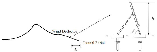
In typical highway wind-blown snow prevention practices, wind deflectors are usually installed at the road shoulder on the windward side of the subgrade. This configuration can effectively block the direct impact of incoming wind on the road ahead, increase airflow velocity above the road, alter the wind-snow flow path, facilitate snow particles being carried by the wind across the target area, and reduce the accumulation risk at key locations. Considering the differences in the wind-snow environment between tunnel portal areas and conventional road sections, the layout method of wind deflectors was appropriately simplified and modified in the numerical simulation. Specifically, the wind deflector was installed in the upper area on the windward side of the tunnel entrance, with the plate body parallel to the tunnel cross-section and covering the main wind flow channel directly in front of the structure. To ensure the feasibility of numerical simulation and clarity of parameter analysis, the following assumptions were adopted in the modeling process: (1) The wind deflector is geometrically simplified as a zero-thickness thin plate structure, ignoring the actual thickness of the plate body. (2) The wind deflector is treated as a rigid non-slip wall in the simulation, without considering structural deformation or damage under wind-snow loads. (3) Material properties and structural connection details of the wind deflector are not involved, and only its function of disturbing the wind-snow flow field is retained. (4) The installation position and orientation of the wind deflector remain fixed during the simulation, without considering dynamic adjustments or displacement caused by extreme wind-snow conditions. The structural diagram of the wind deflector is presented in Figure 4.
Figure 4.
Structural diagram of wind deflector.
Wind deflectors feature a simple and stable overall structure and can be arranged at a fixed or adjustable angle. In terms of geometric parameter definition, this type of wind deflector mainly includes three core control parameters:
- (1)
- Top installation height (h): the vertical height from the upper edge of the wind deflector to the ground, reflecting the coverage range of airflow interference by the plate body.
- (2)
- Plate inclination angle (β): the angle between the wind deflector and the ground, which affects the flow path and velocity variation of airflow above the structure.
- (3)
- Horizontal distance from the tunnel portal (L): the horizontal distance between the leading edge of the wind deflector and the tunnel entrance, determining whether its disturbance core covers the high-risk area of the portal. These three parameters constitute the core geometric control variables of the wind deflector and will be used as variation factors in simulations for single-factor analysis and combined optimization experiments. By adjusting their combinations, different layout conditions with varying disturbance intensities and angles can be constructed, thereby observing their impacts on near-surface wind speed variations, snow particle transport paths, and deposition intensity.
3.1.1. Selection of Control Parameters for Wind Deflectors
Prior to conducting numerical simulations of wind deflector-based protection at tunnel portals, the values of three key design parameters of the wind deflector—top installation height (h), plate inclination angle (β), horizontal distance from the tunnel portal (L), and inlet wind speed (v) were determined. The value ranges are presented in Table 1 below.
Table 1.
Value ranges of simulation parameters for wind deflectors.
Among these, the top installation height ranges from 1.50 m to 2.50 m, covering typical configurations from low-disturbance to high-coverage scenarios; the plate inclination angle is set from 60° to 80°, considering the wind-snow guiding capacity under different flow-around effects; the horizontal distance between the wind deflector and tunnel portal is set from 4 m to 10 m to evaluate its ability to adjust wind speed structure and snow particle migration paths at different positions. In addition, the inlet wind speed of the simulated wind field is uniformly set to 12.75 m/s, corresponding to the maximum design wind-snow conditions in the region, to ensure the analysis results possess a degree of extremeness and engineering representativeness.
3.1.2. Establishment of Wind Deflector Model
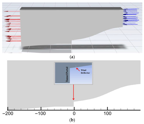
The computational fluid domain selected for the flow field model has a length of 400 m: the horizontal distance between the inlet boundary and the tunnel portal section is 200 m, the horizontal distance between the tunnel portal section and the outlet boundary is 200 m, the overall width of the flow field is 200 m, and the vertical height of the computational domain is 150 m. The negative x-axis direction is defined as the incoming flow direction, the negative z-axis direction as the direction of gravitational acceleration; the left and right sides of the domain are the outflow and inflow surfaces, respectively, and the bottom is a non-slip boundary. Considering extreme wind-blown snow disaster conditions, the wind-snow flow direction is set perpendicular to the tunnel portal section. The fluid domain and wind deflector model are presented in Figure 5.
Figure 5.
Fluid domain and wind deflector model. (a) Fluid domain model; (b) Wind deflector model.
3.1.3. Setting of Solution Parameters
- (1)
- The boundary conditions of the model are set as presented in Table 2.Table 2. Boundary Condition Setting.
- (2)
- The Fluent solver parameters are set as shown in Table 3.Table 3. Solver Parameter Settings.
- (3)
- Convergence condition setting
In the Fluent numerical simulation, a transient incompressible flow model was employed for calculations, with the Realizable k-ε model selected for the turbulence term. Strict convergence criteria were imposed during the numerical solution process to ensure the stability and reliability of simulation results. Specifically, the residual of the continuity equation was converged to below 10−4, and the residuals of the momentum equation, turbulent kinetic energy equation, and turbulent dissipation rate equation were converged to below 10−5. Numerical iteration continued until the residuals of each control equation decreased stably and the residual curve exhibited no significant oscillations, at which point the wind field was deemed converged.
3.1.4. Grid Independence Verification
In numerical simulation, the rationality of grid division directly affects the accuracy and reliability of calculation results. This study adopted the finite volume method to discretize and solve the control equations. The selection of grid size and density must balance computational efficiency and accuracy: since the relationship between grid quantity and computational accuracy is not simply linear, excessive grid refinement may improve accuracy but lead to a significant increase in computational cost. Therefore, grid independence verification is necessary to determine the optimal grid scheme, ensuring that calculation results are not significantly affected by grid division. Based on the characteristics of the wind-blown snow numerical model, a non-uniform grid division strategy was applied to the computational domain: relatively sparse grids were used in areas with gentle wind-snow flow variations (e.g., inlets, outlets, top surfaces, and symmetry boundaries) to conserve computational resources, while local grid refinement was implemented in regions with large flow field gradients (e.g., near the ground and around the subgrade) to accurately capture drastic changes in wind-snow flow. For transient calculations, the matching between time step and grid size is particularly critical—especially the setting of boundary layer grids, which directly impacts computational convergence and accuracy.
Considering the strong turbulent characteristics of wind-blown snow phenomena, boundary layer grids were employed near the fluid domain walls, with solutions obtained using the wall function method. To ensure the applicability of the wall function, the height of the first grid layer must satisfy the requirements of the turbulent core region (i.e., the dimensionless height from the ground is between 20 and 500). In this study, the first grid height was set to 100, the boundary layer grid growth rate to 1.2, and the number of layers to 5. This configuration not only meets the computational requirements of the wall function but also avoids loss of computational efficiency due to overly dense grids. For grid independence verification, three grid schemes (coarse, medium, and fine) were selected for comparative analysis, with grid quantities increasing by a factor of 1.5 sequentially. By monitoring the variation trends of key parameters (e.g., near-surface wind speed distribution and snow phase volume fraction) with grid refinement, it was found that the difference between the calculation results of the medium and fine grids is less than 3%, indicating that the medium grid provides sufficient computational accuracy. The medium grid scheme was therefore ultimately adopted, optimizing computational efficiency while ensuring result reliability.
3.2. Single-Factor Analysis of Key Parameters of Wind Deflectors
Three geometric parameters—the top installation height of the wind deflector, its inclination angle, and its horizontal distance from the tunnel portal—are selected for analysis, and multiple representative values are set for comparative simulation, respectively. After the simulation is completed, by extracting the wind speed cloud map and snow phase concentration distribution map, the wind deflector’s regulation of the near-surface disturbance range, recirculation zone intensity, and snow particle deposition trend is analyzed, and the differences in prevention and control effects of the wind deflector under different layout forms and key influencing factors are further clarified.
3.2.1. Horizontal Distance Between Wind Deflector and Tunnel Portal
To clarify the influence of the horizontal distance between the wind deflector and tunnel portal on the wind-blown snow disturbance effect, following the single-factor variation principle, the horizontal distance between the front edge of the wind deflector and tunnel portal is set to 4 m, 6 m, 8 m, and 10 m for simulation and comparative analysis. At the same time, to effectively evaluate the overall intervention effect of the wind deflector, a control group without a wind deflector is also established, representing the natural development state of wind-blown snow as the benchmark condition. Other parameters remain consistent across all simulation groups: the top height of the wind deflector is fixed at 2 m, the plate inclination angle is fixed at 80°, and the incoming wind speed is set to 12.75 m/s, corresponding to the basic wind speed with a 50-year return period in the study area. All simulations adopt the same grid division method, boundary conditions, and convergence control standards.
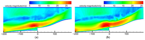
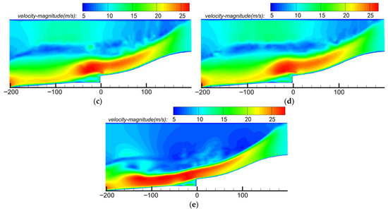
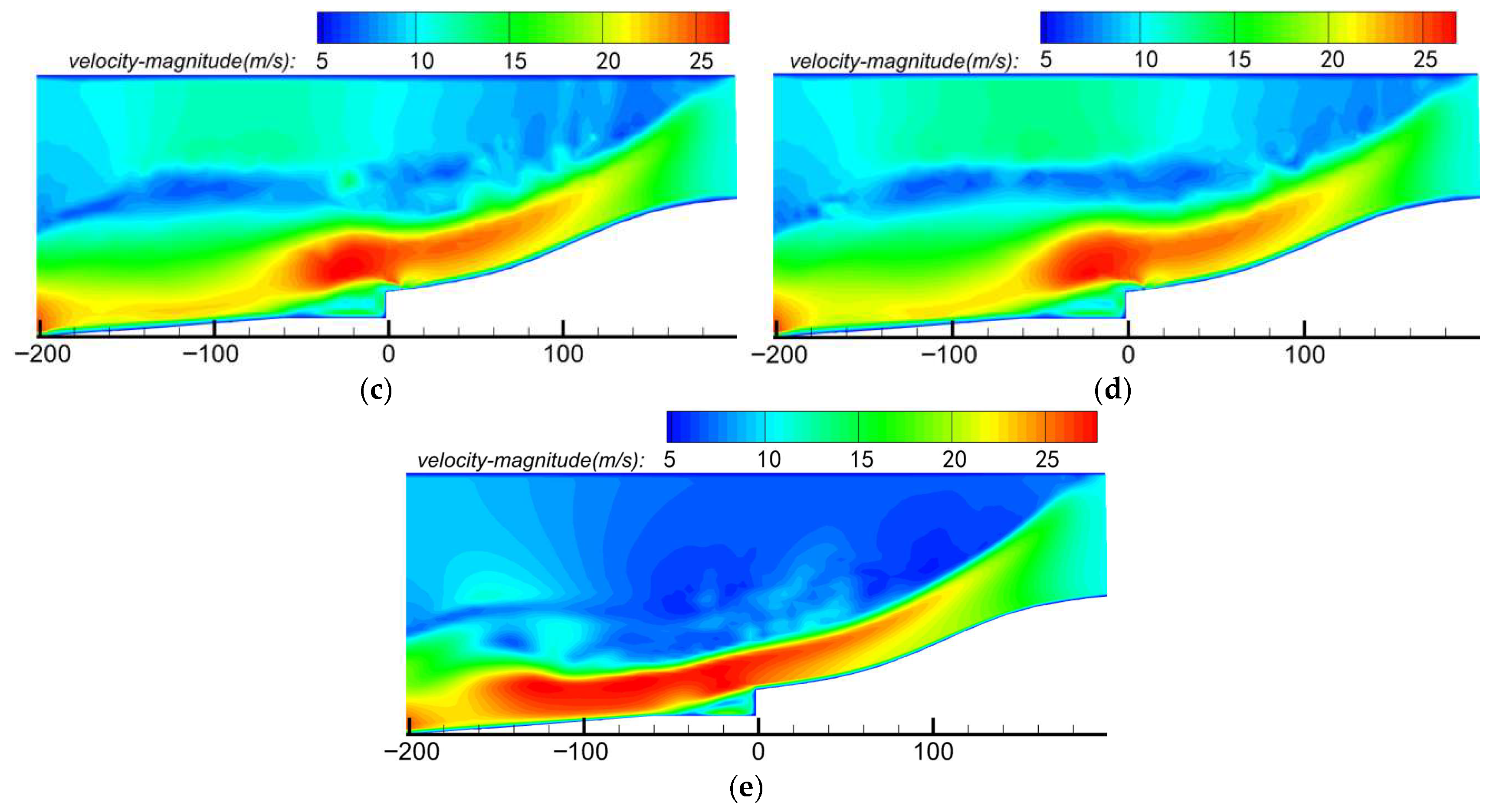
Figure 6 presents the numerically simulated wind speed cloud maps of the flow field around the tunnel portal with wind deflectors installed at different horizontal distances. Comprehensive comparative analysis of these cloud maps reveals that, under the condition without a wind deflector, airflow decelerates rapidly at the tunnel portal’s windward slope after crossing terrain uplift. Near-surface wind speeds in front of the portal are generally below 8 m/s, with a wide, stable recirculation zone forming in the leeward area. This zone exhibits disordered flow direction and low wind speeds, making it prone to snow particle accumulation and deposition—resulting in “portal snow blockage”. The low-wind region extends 40–60 m downstream from the portal’s trailing edge, presenting a significant deposition risk; when the wind deflector is installed 4 m from the tunnel portal, the disturbance zone is close to the portal’s front edge: incoming flow contracts and lifts rapidly beneath the deflector, with local wind speeds in front of the plate increasing by approximately 20%. However, the excessively short distance limits full disturbance development: a strong shear zone forms between the wind deflector’s bottom edge and the ground, and closed small-scale circulation tends to occur behind the plate. This leads to localized wind speed reduction, with snow particles still exhibiting retention and backflow deposition tendencies. Prevention efficacy is improved compared to the control group but fails to fundamentally alleviate risk; at a 6 m distance, the disturbance range precisely covers the main airflow development zone in front of the portal, with the deflector providing sufficient airflow guidance—significantly lifting the main incoming flow path, increasing near-surface wind speeds, compressing the original recirculation zone, and reducing its area while shifting its boundary downstream. The high-wind zone is concentrated 10–40 m in front of the portal, effectively delaying snow particle deposition, minimizing the low-wind area, and achieving the most uniform near-surface wind speeds. Its snow prevention performance is significantly superior to other configurations; at an 8 m distance, the disturbance flow core deviates from the portal’s main airflow channel, with the wind-guiding effect concentrated 10–50 m from the portal. This causes wind speed reduction directly in front of the portal and reformation of a near-surface low-wind zone. While it homogenizes speeds in the downstream area, it fails to inhibit initial snow particle deposition near the portal—with recirculation zone redevelopment, wind speed reduction, and increased accumulation risk; at a 10 m distance, the disturbance zone is far from the main wind-snow flow development path: airflow near the portal resembles natural conditions, with significant wind speed reduction on the windward side and a large symmetric recirculation zone forming leeward. The wind speed structure is highly similar to the no-deflector condition, with effective intervention capability almost lost and accumulation risk approaching benchmark levels.
Figure 6.
Wind speed cloud maps of the flow field around the tunnel portal at different horizontal distances. (a) L = 4 m; (b) L = 6 m; (c) L = 8 m; (d) L = 10 m; (e) Control group.
In summary, wind deflector position exerts a significant influence on wind field disturbance range: excessively short distances restrict full wind-guiding development, with plate-bottom shear inducing local deposition; excessively long distances render intervention ineffective, failing to control low-wind development in front of the portal. At a 6 m distance, the disturbance zone precisely covers the key snow particle transport channel (0–40 m upstream of the portal), significantly increasing near-surface wind speeds and compressing the recirculation zone—exhibiting optimal wind field regulation performance.
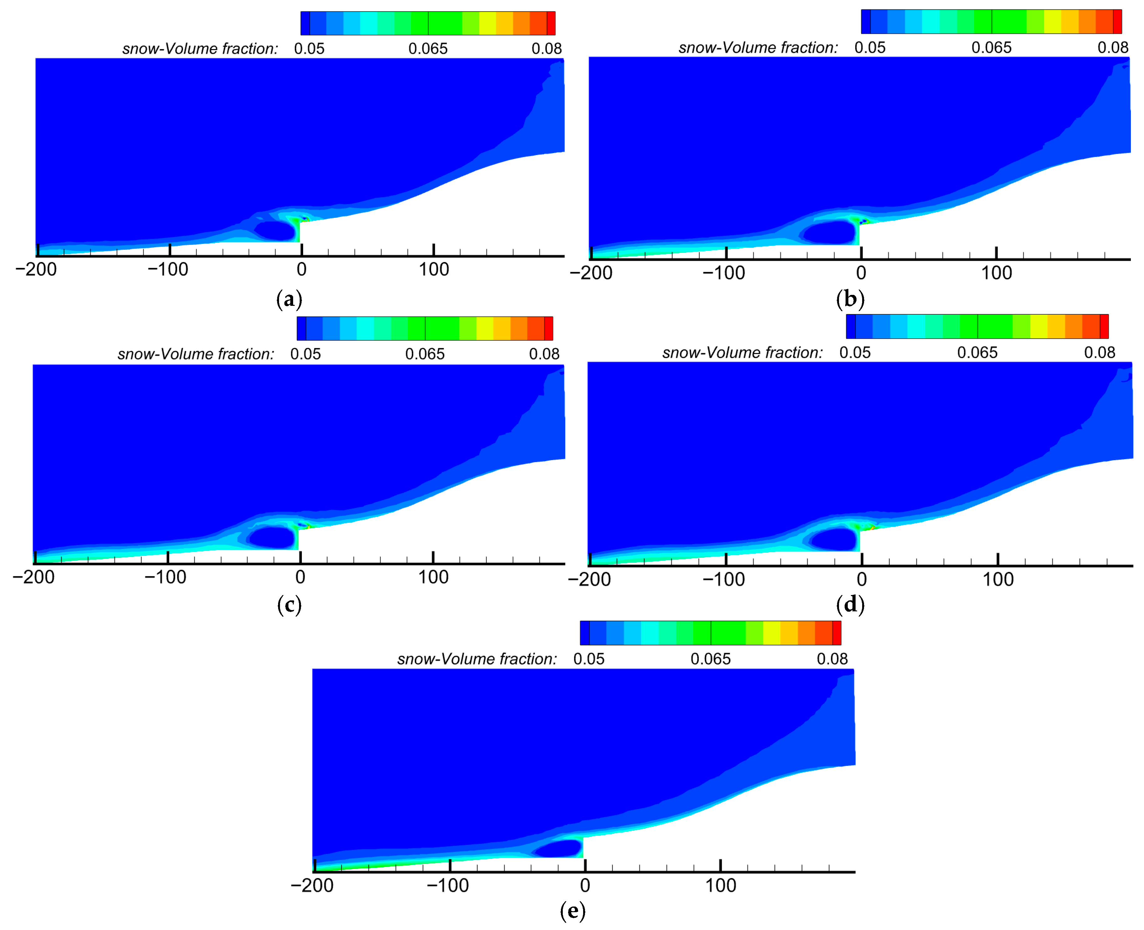
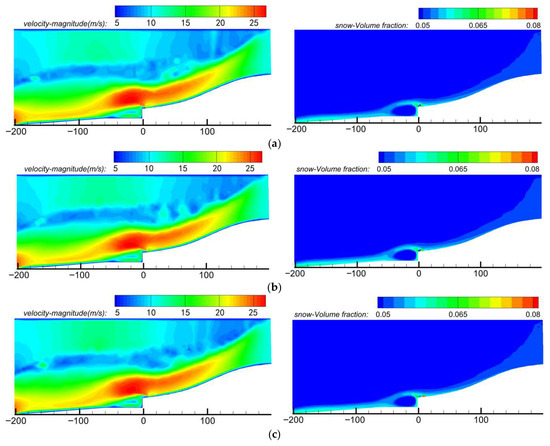
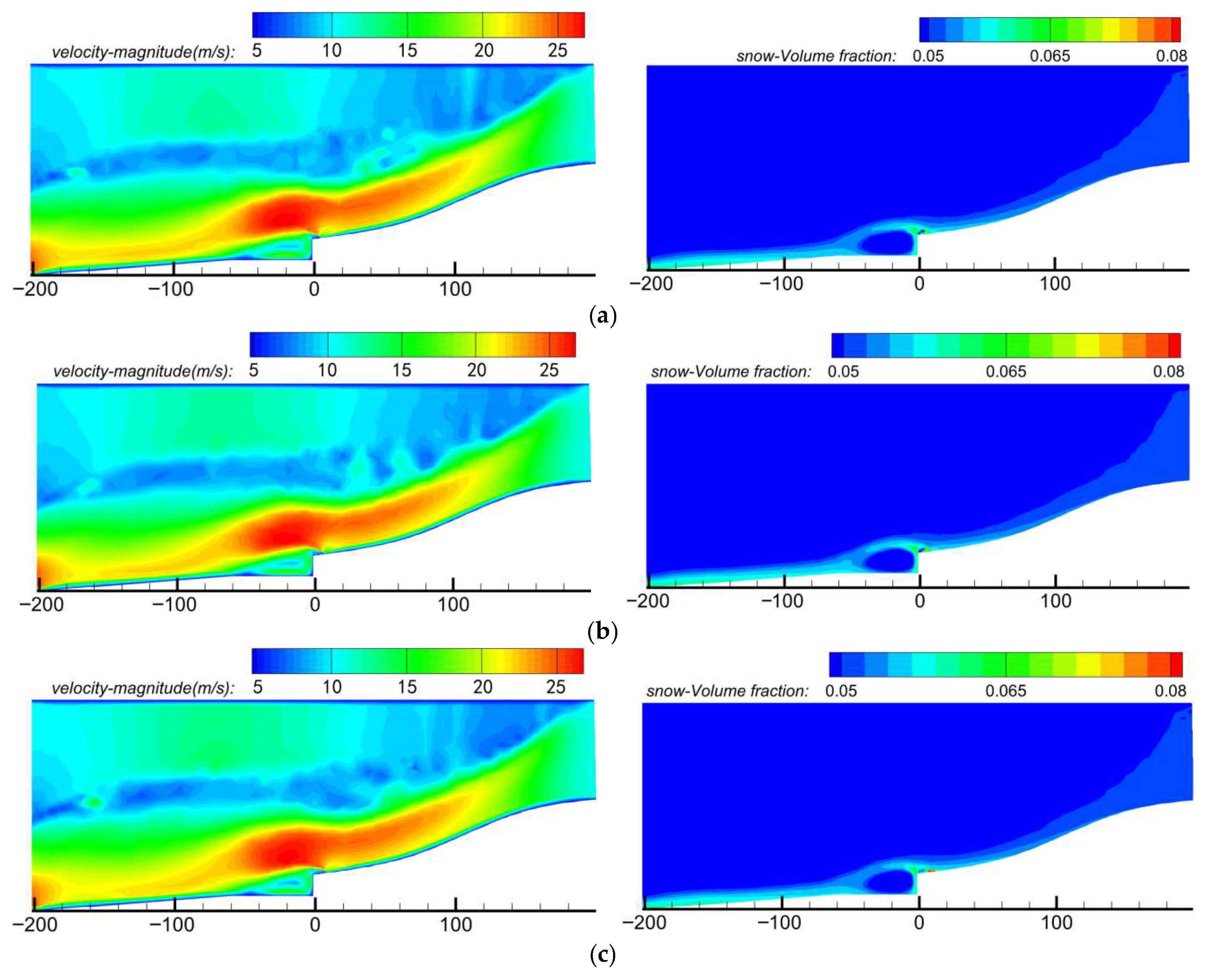
To further verify the effect of wind field regulation structures on wind-blown snow accumulation trends, snow phase volume fraction cloud maps under different layout conditions are extracted for comparative analysis. By observing variations in snow particle distribution intensity and deposition range around the portal and combining these with the aforementioned wind speed structure characteristics, the actual impact of wind deflector installation distance on wind-blown snow prevention efficacy is further evaluated from the perspective of snow particle transport and accumulation. Figure 7 presents numerically simulated snow phase concentration cloud maps around the tunnel portal for wind deflectors installed at different horizontal distances.
Figure 7.
Snow phase concentration cloud maps around the tunnel portal at different horizontal distances. (a) L = 4 m; (b) L = 6 m; (c) L = 8 m; (d) L = 10 m; (e) Control group.
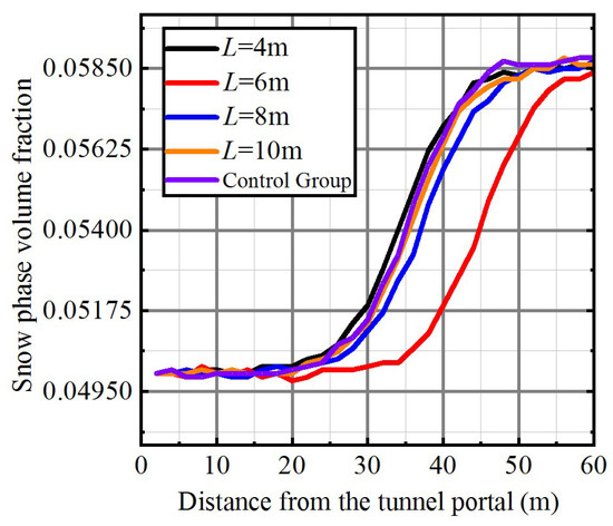
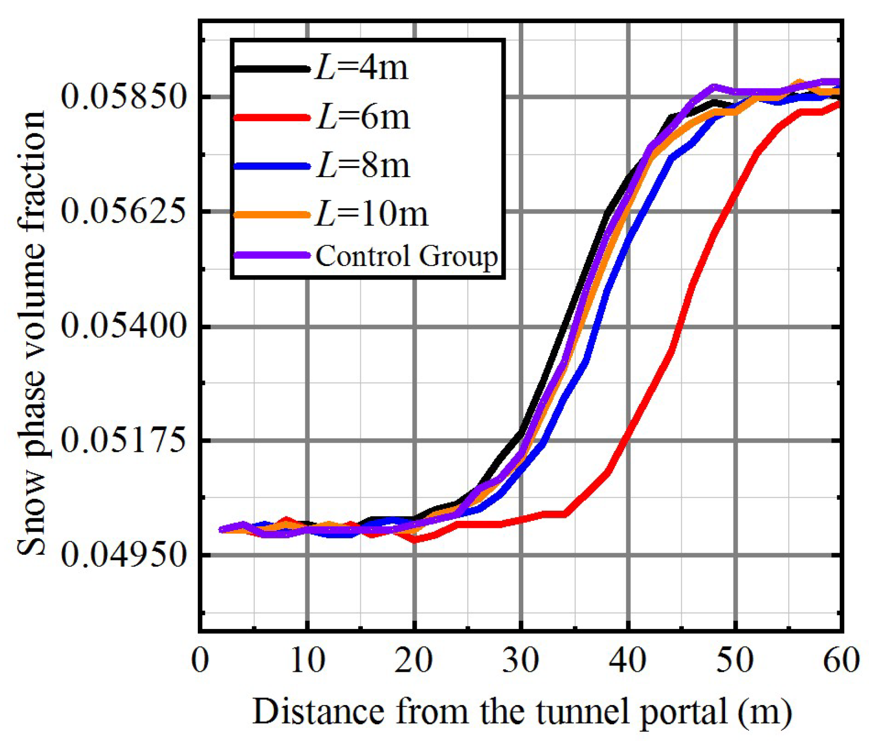
Ground monitoring points are established at 2 m intervals within the 60 m range in front of the tunnel portal, and snow phase volume fractions around the portal at different wind deflector horizontal distances are extracted. The corresponding distribution diagram is presented in Figure 8 and Table 4.
Figure 8.
Snow Phase Volume Fraction Diagram Around the Tunnel Portal at Different Horizontal Distances.
Table 4.
Comparison of Snow Phase Volume Fractions at Different Horizontal Distances.
To verify the actual effect of wind deflectors with different layout distances on snow particle migration and deposition, snow phase volume fraction cloud maps under each working condition are extracted for comparative analysis, and key findings are combined with wind speed distribution characteristics and quantitative indicators as follows:
Under the control condition (no wind deflector), significant snow particle accumulation occurs at and downstream of the tunnel portal. The accumulation area is highly consistent with the leeward low-wind zone identified in wind field analysis, with a maximum volume fraction exceeding 0.06 and a wide snow particle retention range—seriously impairing the traffic capacity of the tunnel portal. Quantitative data show that the average wind speed at the portal is only 7.2 m/s, the recirculation zone length reaches 45.8 m, and no snow reduction effect is achieved.
When the wind deflector is installed at 4 m, although the snow deposition area shifts slightly, high-value regions remain concentrated within approximately 20 m of the portal, and the accumulation core remains close to the portal. This indicates insufficient disturbance development, with the near-surface recirculation zone still exerting a strong aggregation effect on snow particles, leading to limited improvement in prevention efficacy. According to Table 4, the average wind speed at the portal increases to 9.2 m/s (a 27.8% increase compared to the control group), the recirculation zone length is compressed to 38.5 m (a 16.0% reduction), and the snow reduction rate is only 8.7%—significantly lower than the optimal condition.
At the optimal layout distance of 6 m, high-concentration snow particle regions shift significantly leeward. The wind deflector effectively modulates the near-surface wind speed structure, elevates the wind field, compresses the stagnation zone, and optimizes snow particle transport paths. Compared with the control group, this distance achieves remarkable quantitative improvements: the average wind speed at the portal increases by 59.7% (to 11.5 m/s), the recirculation zone length is compressed by 51.3% (to 22.3 m), and the snow phase volume fraction is reduced by 12.3%—representing the optimal layout position for comprehensive prevention and control under current working conditions.
When the layout distance is increased to 8 m and 10 m, high-concentration snow particle regions shift upstream again, with expanded deposition ranges. This demonstrates that the wind deflector’s disturbance zone deviates from the main snow particle transport path, weakening its regulatory capacity. Quantitative results confirm this trend: at 8 m, the average wind speed at the portal drops to 8.8 m/s, the recirculation zone length rebounds to 35.7 m, and the snow reduction rate decreases to 8.5%; at 10 m, the indicators are even closer to the control group (average wind speed 7.6 m/s, recirculation zone length 42.1 m, snow reduction rate 6.9%). Notably, when L deviates from 6 m (e.g., 4 m or 8 m), the snow reduction rate drops by 30–35%, which further confirms the critical role of horizontal distance in wind field regulation and snow particle deposition control.
3.2.2. Angle Between Wind Deflector and Ground
The wind deflector is set at inclination angles of 60°, 65°, 70°, 75°, and 80° for simulation and comparative analysis. A control group without a wind deflector is also established, representing the natural development state of wind-blown snow as the benchmark condition. All other parameters are kept consistent across simulations: the top height of the wind deflector is fixed at 2 m, its horizontal distance from the tunnel portal is fixed at 6 m, and the incoming wind speed is set to 12.75 m/s (corresponding to the basic wind speed with a 50-year return period in the study area). All simulations adopt the same grid division method, boundary conditions, and convergence control criteria.
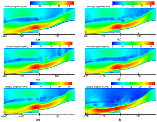
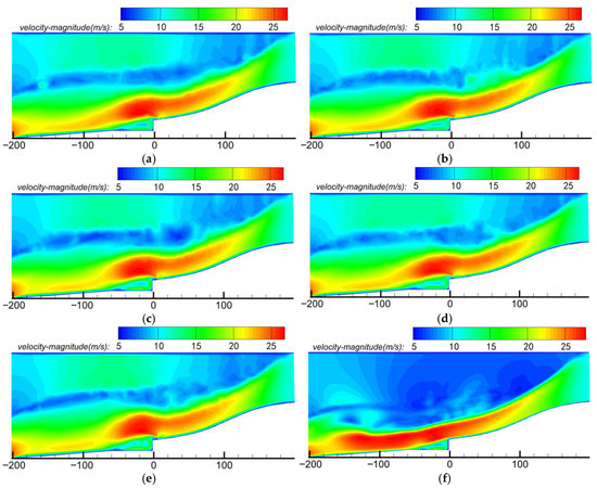
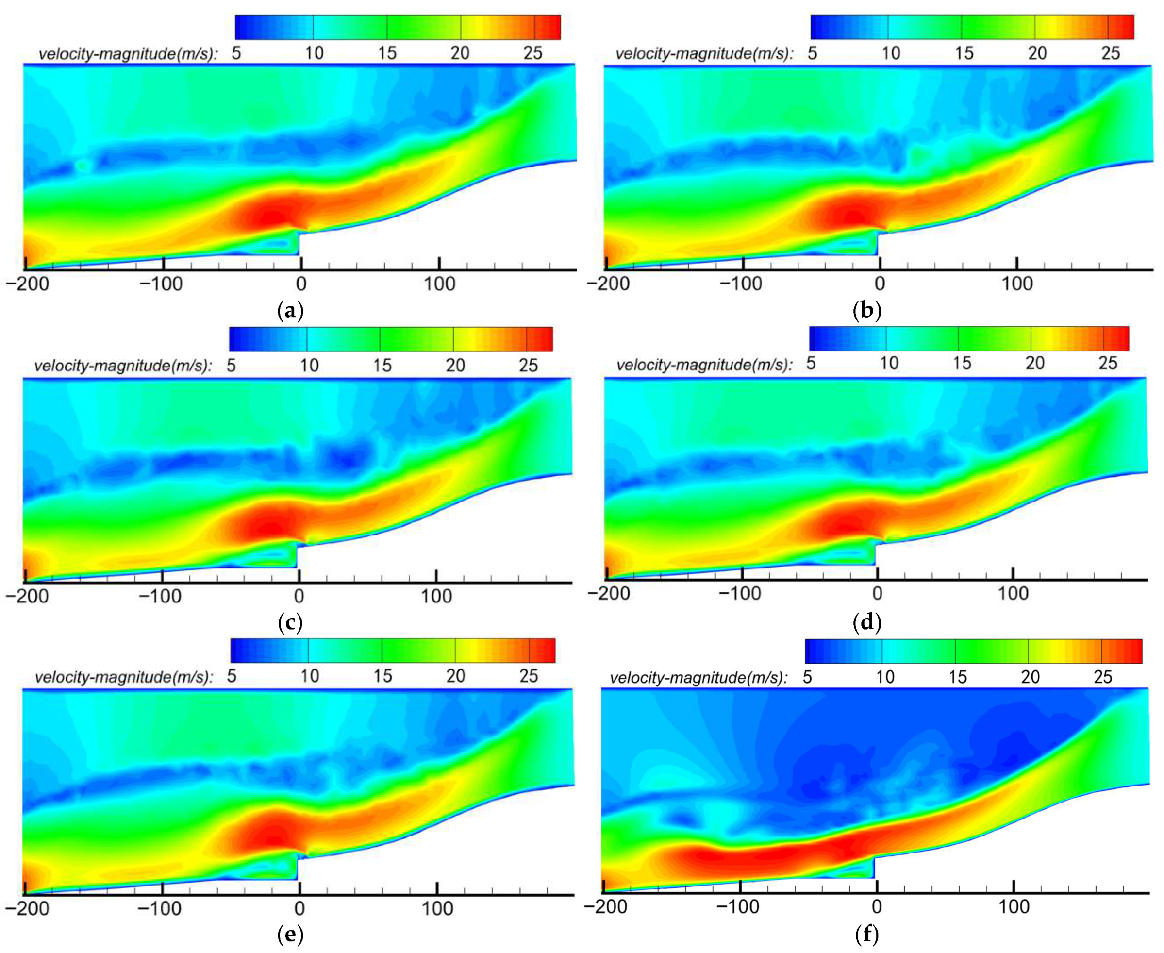
Figure 9 presents the wind speed cloud maps of the flow field around the tunnel portal for wind deflectors with different inclination angles. At a 60° wind deflector-to-ground angle, wind speeds on the tunnel’s leeward side increase significantly, with peak speeds (approximately 25 m/s) observed 30–40 m in front of the portal. This effectively enhances airflow kinetic energy, enabling wind-blown snow to rapidly traverse the tunnel portal area. Leeward wind speeds rise from below 10 m/s to 10–12 m/s, drastically reducing the extent of low-wind zones and minimizing snow accumulation risk. The wind speed cloud map confirms that the acceleration zone at this angle is the longest (30–40 m), with significant and sustained wind speed elevation extending to the critical area ahead of the portal—yielding optimal wind field optimization, effective snow particle transport, and the lowest accumulation risk, thus demonstrating superior wind speed enhancement and snow prevention performance.
Figure 9.
Wind speed cloud maps of the flow field around the tunnel portal at different inclination angles. (a) β = 60°; (b) β = 65°; (c) β = 70°; (d) β = 75°; (e) β = 80°; (f) Control group.
At a 65° angle, wind speeds on the windward side further increase to nearly 25 m/s, with the acceleration zone extending to 40–50 m (facilitating snow particle transport). However, leeward wind speed gains are limited: near-surface speeds 30–50 m downstream of the portal remain below 10 m/s. While intervention efficacy is improved, the leeward low-wind zone still drives substantial snow accumulation, with persistent accumulation risk within 30 m downstream of the portal.
At angles of 70–80°, windward speeds increase markedly (exceeding 25 m/s), and the acceleration zone extends beyond 50 m. Conversely, leeward wind speed enhancement weakens progressively: despite continued windward speed gains, leeward increases are minimal, and low-speed zones remain extensive. Cloud maps indicate that while the acceleration zone is extended and windward speeds are elevated, insufficient leeward wind speeds fail to compress low-speed zones effectively—resulting in unregulated (and potentially expanded) snow accumulation areas.
Overall, windward speeds increase monotonically with wind deflector angle, but leeward control efficacy does not improve proportionally. The 60° configuration achieves optimal wind field regulation: balanced windward speed elevation, effective leeward speed enhancement, the smallest snow accumulation area, and superior prevention performance. In contrast, 70° and 80° deflectors—though boosting windward speeds significantly—exhibit limited leeward speed gains, exacerbating backflow in low-speed zones and increasing snow accumulation risk.
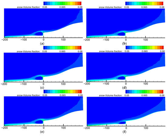
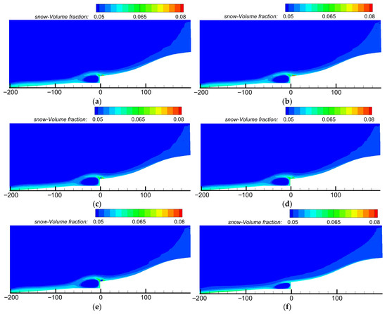
Figure 10 presents the snow phase concentration cloud maps around the tunnel portal for wind deflectors with different inclination angles.
Figure 10.
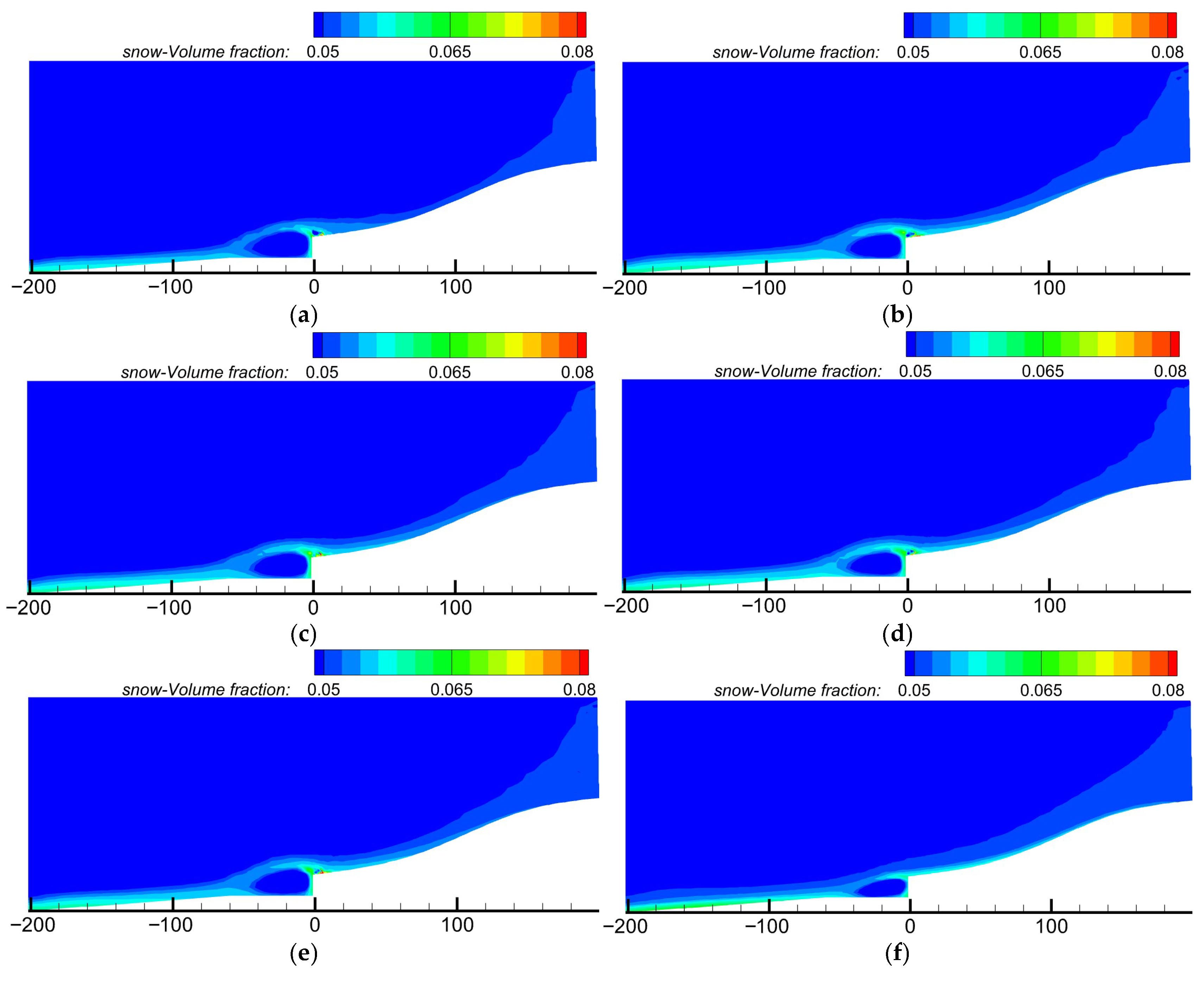
Snow phase concentration cloud maps around the tunnel portal at different inclination angles. (a) β = 60°; (b) β = 65°; (c) β = 70°; (d) β = 75°; (e) β = 80°; (f) Control group.
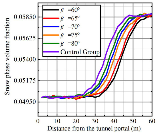
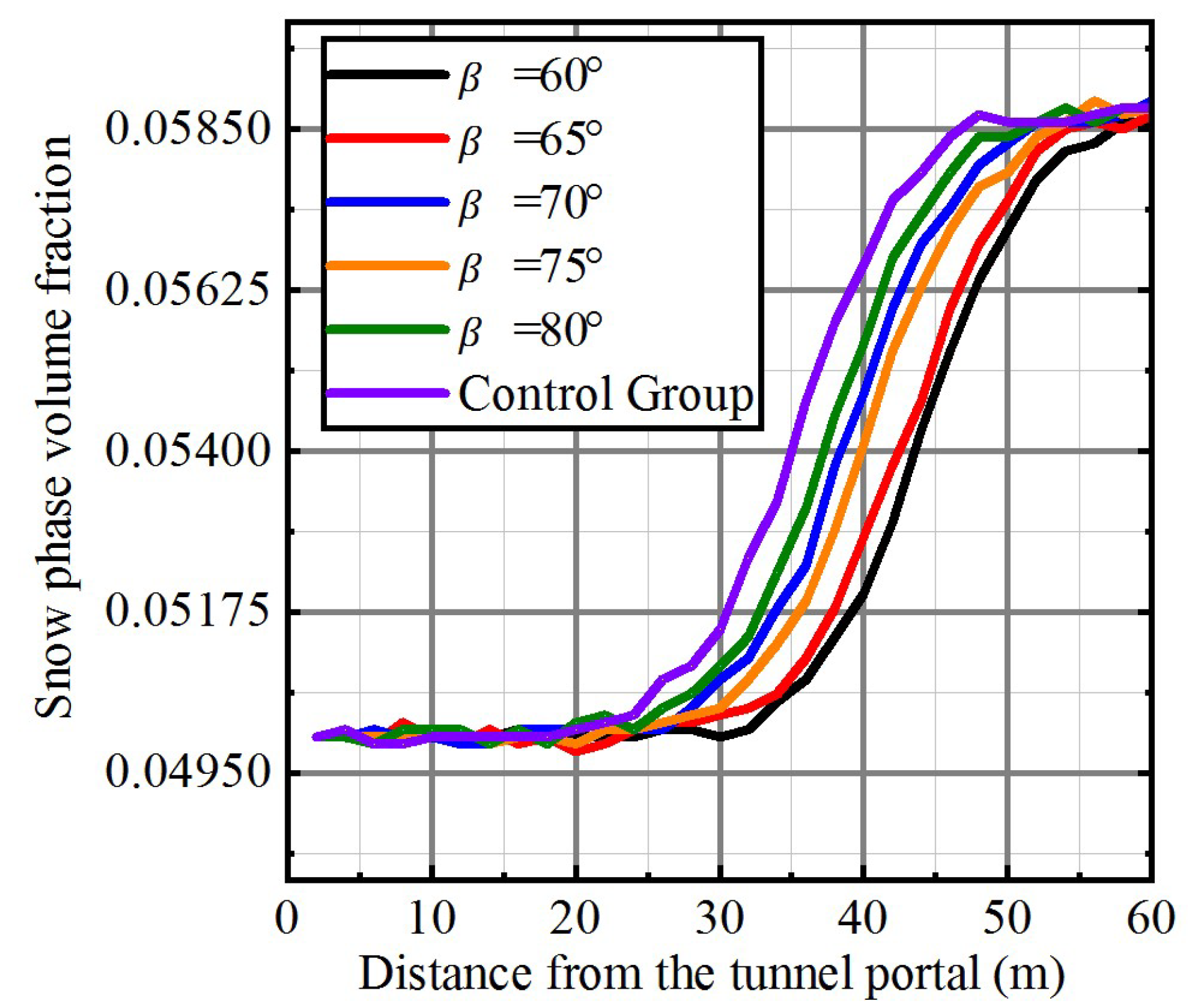
Ground monitoring points are established at 2 m intervals within the 60 m range in front of the tunnel portal, and snow phase volume fractions around the portal under different wind deflector inclination angles are extracted. The corresponding snow phase volume fraction distribution diagram is presented in Figure 11 and Table 5.
Figure 11.
Snow Phase Volume Fraction Diagram Around the Tunnel Portal at Different Inclination Angles.
Table 5.
Comparison of Snow Phase Volume Fractions at Different Inclination Angles.
By comparing snow phase volume fraction distribution characteristics under different wind deflector inclination angles, the influence mechanism of angle parameters on snow particle transport processes can be elucidated. Numerical simulation results reveal a significant nonlinear relationship between wind deflector angle and snow accumulation prevention efficacy. Among the tested angles, the 60° wind deflector exhibits optimal snow particle regulation performance, with its snow phase volume fraction cloud map displaying three distinct characteristics: the snow volume fraction in the area ahead of the tunnel portal is the lowest (0.0525), representing a 12.3% reduction compared to the no-deflector condition; the high-concentration snow accumulation zone shifts significantly leeward, with the maximum accumulation position moving downstream by approximately 25 m; the snow accumulation distribution range is markedly reduced, with high-value regions disappearing entirely. These features indicate that the 60° angle generates the most effective wind field lifting effect, enabling snow particles to acquire sufficient kinetic energy to traverse the tunnel area.
The regulation effect of the 65° wind deflector is significantly attenuated: while windward wind speeds are increased, the leeward snow volume fraction (0.0542) is 3.2% higher than under the 60° condition, and the high-concentration zone expands by 15%. Cloud map analysis shows insufficient airflow lifting height at this angle, leading to premature settlement of snow particles near the tunnel portal. This “semi-lifted” state instead forms a new snow accumulation zone on the leeward side.
Snow particle regulation capacity further weakens at angles of 70–80°, with snow phase volume fraction curves exhibiting a “high upstream, low downstream” distribution pattern. Cloud map results demonstrate that excessively large angles enhance windward wind speeds but trigger early airflow separation, generating strong downwash flow. This flow field structure fails to effectively transport snow particles and additionally creates a new deposition zone in front of the tunnel portal.
In summary, snow accumulation distribution characteristics under each angle condition are highly correlated with corresponding wind field parameters. The optimal operating condition occurs at a 60° wind deflector inclination angle, which generates continuous, stable accelerated airflow on the windward side while maintaining sufficient transport wind speeds on the leeward side. The optimal angle must satisfy dual requirements: adequate windward acceleration and sustained leeward transport capacity.
3.2.3. Top Installation Height of Wind Deflector
The top installation height of the wind deflector is set to 1.5 m, 1.75 m, 2 m, 2.25 m, and 2.5 m for simulation and comparative analysis. A control group without a wind deflector is also established, representing the natural development state of wind-blown snow as the benchmark condition. All other parameters are kept consistent across simulations: the horizontal distance from the tunnel portal is fixed at 6 m, the plate inclination angle is fixed at 80°, and the incoming wind speed is set to 12.75 m/s (corresponding to the basic wind speed with a 50-year return period in the study area). All simulations adopt the same grid division method, boundary conditions, and convergence control criteria.
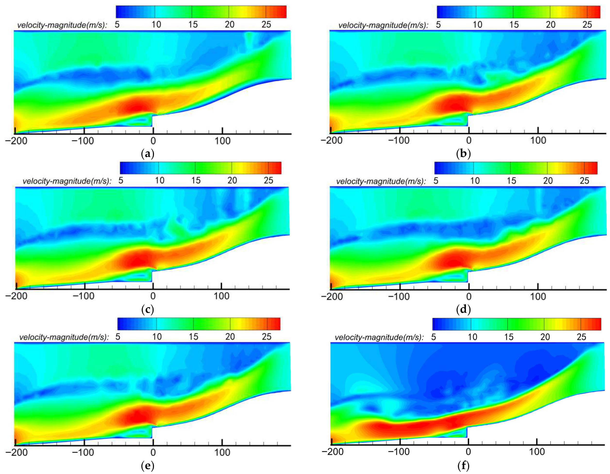
Figure 12 presents the wind speed cloud maps of the flow field around the tunnel portal for wind deflectors with different top installation heights.
Figure 12.
Wind speed cloud maps of the flow field around the tunnel portal at different installation heights. (a) h = 1.50 m; (b) h = 1.75 m; (c) h = 2.00 m; (d) h = 2.25 m; (e) h = 2.50 m; (f) Control group.
The top installation height of the wind deflector exerts a significant influence on the wind speed field and snow accumulation prevention efficacy:
At a height of h = 1.5 m, the wind speed acceleration zone is short, with relatively limited wind speed enhancement. While windward speeds are increased to some extent, the effect is weak; leeward speed gains are also limited, low-speed zones persist, and snow accumulation risk remains high.
As height increases to h = 1.75 m to 2.0 m, the deflector’s intervention effect gradually strengthens. Notably, at h = 2.0 m, windward speed enhancement is most significant: the acceleration zone extends to 20–30 m in front of the tunnel portal, leeward speeds increase progressively, low-speed zones shrink, and snow accumulation is effectively mitigated.
At heights of h = 2.25 m to 2.5 m, wind speed enhancement is further amplified—windward speeds reach a maximum, the acceleration zone extends to 30–40 m in front of the portal, and leeward speeds continue to rise, reducing snow accumulation risk further. However, the marginal improvement in prevention efficacy becomes negligible.
Overall, wind speed enhancement effects strengthen with increasing deflector height: windward speed gains are pronounced, leeward speeds improve significantly, and snow accumulation risk is substantially reduced. At lower heights (e.g., h = 1.5 m), speed enhancement is limited, snow accumulation areas are extensive, and risk is high. The optimal performance is achieved at h = 2.0 m, where wind speed gains are significant, and snow accumulation risk is minimized. Beyond 2.0 m, while wind speed enhancement continues, marginal efficiency gains diminish, and snow accumulation risk stabilizes after reaching a critical height.
In practical applications, the deflector’s installation height must be optimally designed based on the tunnel portal’s wind-snow environment and safety requirements. Numerical simulation results confirm h = 2.0 m as the optimal height: it effectively elevates wind speeds, compresses snow accumulation areas, and minimizes the impact of wind-blown snow disasters.
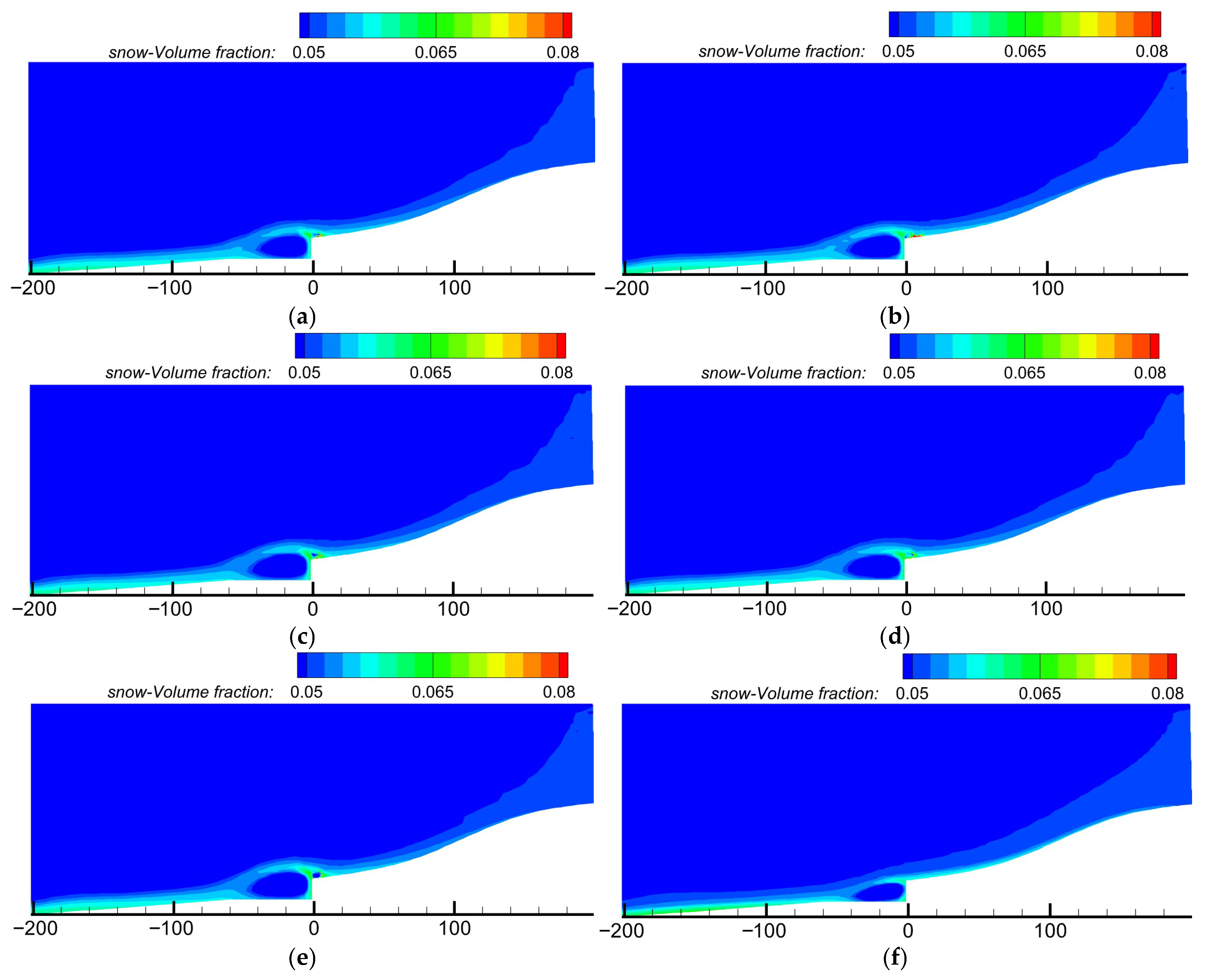
Figure 13 shows the snow phase concentration cloud maps around the tunnel portal for wind deflectors with different top installation heights.
Figure 13.
Snow phase concentration cloud maps around the tunnel portal at different installation heights. (a) h = 1.50 m; (b) h = 1.75 m; (c) h = 2.00 m; (d) h = 2.25 m; (e) h = 2.50 m; (f) Control group.
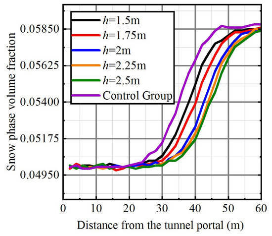
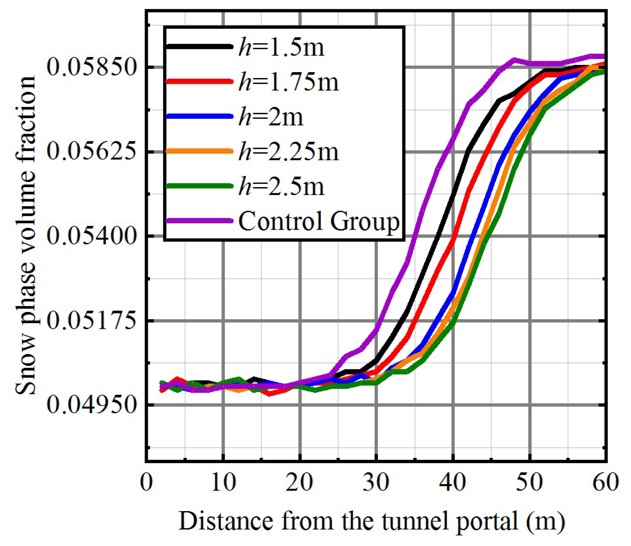
Ground monitoring points are established at 2 m intervals within the 60 m range in front of the tunnel portal, and snow phase volume fractions around the portal for wind deflectors with different top installation heights are extracted. The corresponding snow phase volume fraction distribution diagram is presented in Figure 14.
Figure 14.
Snow phase volume fraction diagram around the tunnel portal at different installation heights.
When the installation height of the wind deflector is 1.50 m and 1.75 m, the snow particle accumulation area changes relative to the control group: At h = 1.50 m, although the windward wind speed is enhanced by 38.9% and the leeward wind speed increases to 8.4 m/s (a 20.0% increase compared to the control group), the snow accumulation area remains concentrated within 30 m of the tunnel portal. The snow phase volume fraction is only slightly reduced to 0.0562, corresponding to a snow reduction rate of merely 4.2%, and a certain snow accumulation risk persists. As the height increases to 1.75 m, the windward wind speed enhancement rate rises to 52.8%, the leeward wind speed reaches 9.3 m/s (a 32.9% increase), and the snow accumulation area is slightly reduced. However, the snow phase volume fraction is still 0.0548 (snow reduction rate 6.6%), and high-value snow accumulation zones are still confined within 30 m, failing to completely resolve the snow accumulation issue.
At heights of 2.00 m and 2.25 m, the snow accumulation control effect is significantly improved. According to Table 6, at h = 2.00 m, the windward wind speed enhancement rate reaches 69.4%, the leeward wind speed increases to 10.2 m/s (a 45.7% increase compared to the control group), and the recirculation zone length is compressed to 22.3 m (a 51.3% reduction). The snow phase volume fraction drops to 0.0525, with a snow reduction rate of 12.3%. At h = 2.25 m, the windward wind speed enhancement rate further rises to 79.2%, the leeward wind speed reaches 10.5 m/s, and the recirculation zone length is further compressed to 20.7 m. The snow phase volume fraction is 0.0522, with a snow reduction rate of 12.8%. At these two heights, the snow accumulation area is significantly reduced, the wind speed field is markedly improved (especially leeward wind speeds, which increase substantially), and snow particle transport paths are effectively optimized. Trends in snow volume fraction indicate that high-concentration snow accumulation zones are significantly compressed, snow volume fractions within 20 m of the tunnel portal are effectively suppressed, and snow accumulation risk is greatly reduced—demonstrating that increasing the wind deflector height has a positive effect on wind field regulation and snow accumulation prevention.
Table 6.
Comparison of Snow Phase Volume Fractions at Different Installation Heights.
When the height is further increased to 2.50 m, changes in the snow accumulation area are relatively minor. Although the windward wind speed enhancement rate climbs to 83.3% and the leeward wind speed reaches 10.6 m/s (the highest among all test groups), the recirculation zone length is only slightly reduced to 19.8 m. The snow phase volume fraction is 0.0520, with a snow reduction rate of 13.2%—an increase of merely 0.4 percentage points compared to h = 2.25 m. The reduction in snow accumulation area is limited, the inhibitory effect on snow accumulation is no longer significant, volume fraction changes are small, and high-concentration snow accumulation zones within 20 m of the tunnel portal are partially restored.
In summary, the snow phase volume fraction curve changes significantly with increasing wind deflector height: At 1.50 m and 1.75 m, the curve exhibits a relatively gentle upward trend, with low wind speed enhancement effects, large recirculation zone lengths (39.2 m and 33.5 m respectively), and high-concentration snow accumulation zones still concentrated near the tunnel portal; at 2.00 m and 2.25 m, the curve rises rapidly, with significant improvements in wind speed enhancement and recirculation zone compression, and high-value snow accumulation zones are significantly suppressed; while the 2.50 m wind deflector yields some marginal improvements in wind speed and recirculation zone indicators, its snow accumulation control effect is negligible, and the curve tends to flatten—indicating that the snow accumulation control effect at this height approaches saturation.
4. Orthogonal Test Design and Simulation Optimization Analysis
Following completion of the single-factor analysis of key wind deflector layout parameters (including distance from the tunnel portal, inclination angle, and installation height), it was found that each parameter exerts a significant regulatory effect on wind field disturbance and snow particle deposition near the tunnel portal, with interactive and nonlinear coupling relationships among the three. To further clarify the contribution of each parameter to snow prevention efficacy under combined conditions, identify dominant factors, and explore the optimal configuration combination, it is necessary to introduce a multi-factor level test design method.
The orthogonal test is an efficient numerical design method that systematically investigates the influence of multiple factors on outcomes while minimizing the number of tests. It enables the extraction of influence laws for multiple objectives and factors, and screening of optimal parameters, while reducing computational resource consumption. Therefore, this section adopts the orthogonal test method, taking wind deflector top height, plate inclination angle, and distance from the portal as the three primary control variables, constructing a standard L9(33) orthogonal design table, and conducting wind-snow two-phase flow simulation analysis. Evaluation indicators are established from two dimensions—wind speed enhancement effect and snow accumulation reduction capacity—to comprehensively assess the prevention and control performance of each combined working condition. By comparing simulation results and conducting range analysis, this section further recommends the optimal combination of wind deflector parameters and verifies its actual efficacy under typical wind-snow working conditions.
4.1. Orthogonal Working Condition Combination and Evaluation Index Design
4.1.1. Orthogonal Working Condition Combination
To explore the influence of different wind deflector layout parameter combinations on the wind-blown snow prevention efficacy at the tunnel portal, three design factors—horizontal distance from the tunnel portal (L), plate inclination angle (β), and top installation height (h)—were selected as the primary control variables for the orthogonal test, based on the results of the single-factor sensitivity analysis. Considering the balance between computational resources and model convergence, three representative levels were set for each factor to construct an L9(33) orthogonal table, and a total of nine groups of wind-snow flow field simulation tests were conducted. The settings of each factor and level are presented in Table 7.
Table 7.
Factors and Levels of Orthogonal Test for Wind Deflectors.
Based on the above parameters, a standard orthogonal test design covering 9 groups of working conditions was constructed, and the specific combinations are presented in Table 8.
Table 8.
L9(33) Orthogonal Test Design Table.
4.1.2. Evaluation Index Design
In the range analysis of the orthogonal test, the average snow phase volume fraction within 20–40 m on the leeward side of the tunnel portal was selected as the evaluation index, which can effectively assess the influence of wind deflector layout on snow accumulation and deposition. This area is a critical range where snow particles begin to accumulate significantly, and the snow accumulation status exerts a substantial impact on the normal operation of the tunnel. By simulating the snow phase volume fraction in this area under different wind deflector parameter combination conditions, the effect of the wind deflector in inhibiting snow accumulation can be intuitively reflected. A low average snow phase volume fraction indicates that the wind deflector has a favorable guiding effect on snow particles, reducing their deposition in this area and mitigating the threat of wind-blown snow disasters to the tunnel portal.
When calculating this evaluation index, snow phase volume fraction data from each discrete point in the area were first extracted from the simulation results, followed by an arithmetic average calculation of these data to obtain the average snow phase volume fraction. In range analysis, this index can clearly reflect the differences in the influence of different wind deflector parameters on snow accumulation and deposition. If the average snow phase volume fraction fluctuates significantly with changes in a specific parameter, this parameter has a significant impact on snow accumulation and deposition; otherwise, its influence is minor. Thus, the importance ranking of each parameter can be determined, and the optimal wind deflector parameter combination can be screened out. Therefore, the snow phase volume fraction at 35 m from the tunnel portal was also selected as a key evaluation index for analysis.
4.2. Numerical Simulation Results and Range Analysis of Orthogonal Test
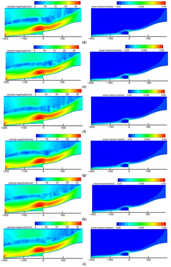
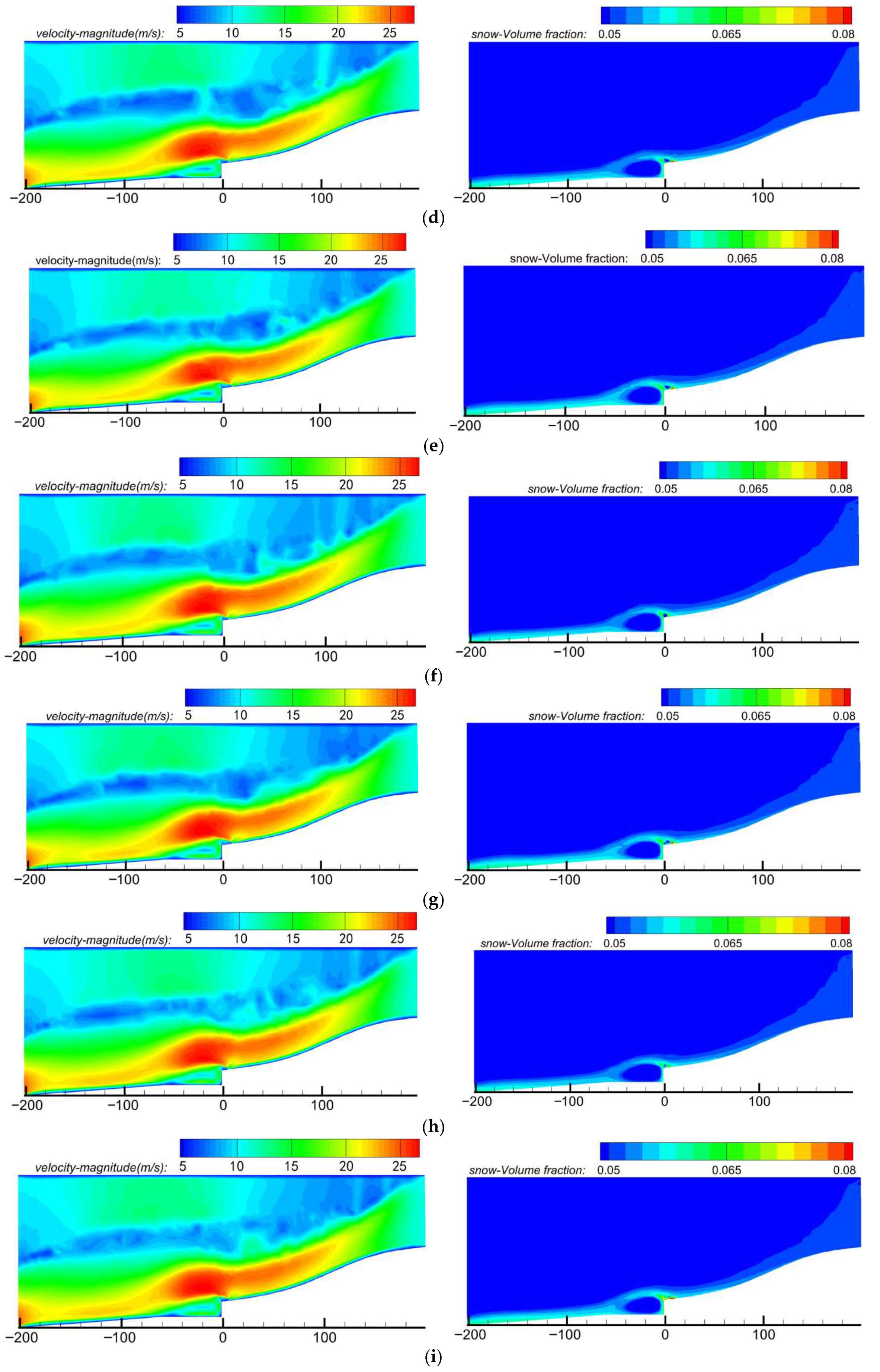
Based on the aforementioned orthogonal test design and combined with the range analysis method, the snow phase volume fraction at 35 m from the tunnel portal under different parameter configurations was quantitatively evaluated. The range analysis method can effectively determine the contribution of each design factor to snow prevention efficacy. By comparing results across different working conditions, the influence of each factor on snow accumulation was quantitatively analyzed, and the optimal design combination was identified. Wind field cloud maps around the tunnel portal and numerical simulation results for the snow phase volume fraction under each working condition are presented in Figure 15 and Table 9.
Figure 15.
Wind field cloud maps and snow phase volume fraction cloud maps around the tunnel portal under each working condition. (a) Condition 1; (b) Condition 2; (c) Condition 3; (d) Condition 4; (e) Condition 5; (f) Condition 6; (g) Condition 7; (h) Condition 8; (i) Condition 9.
Table 9.
Numerical Simulation Results of Snow Phase Volume Fraction Under Each Working Condition.
The range calculation formula is:
where: Kij is the sum of the snow phase volume fractions for level i of the j-th factor; represents the average value of Kij; R is the range.
Through calculation and analysis using the aforementioned formula, Table 10 for the orthogonal test was derived.
Table 10.
Range Analysis Table of Snow Phase Volume Fraction.
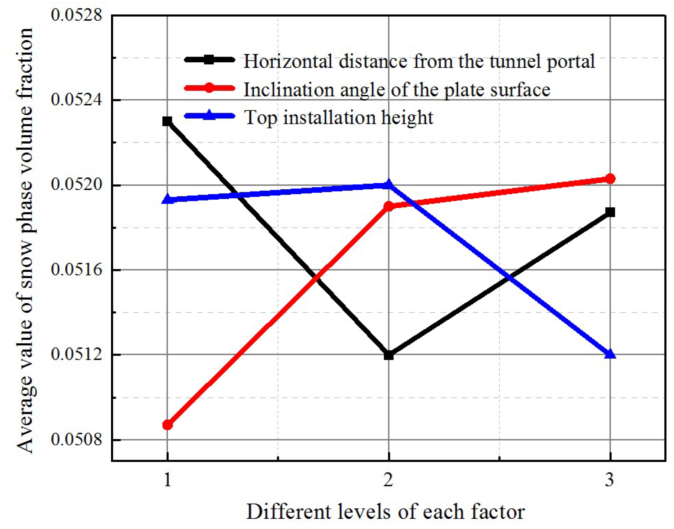
According to the above calculations, the ranges corresponding to the horizontal distance from the tunnel portal, the plate inclination angle, and the top installation height are 0.00143, 0.00080, and 0.00083, respectively, that is, RA > RC > RB. Among them, the horizontal distance from the tunnel portal has a significant influence.
The analysis of variance was performed, and the results are presented in Table 11.
Table 11.
Analysis of Variance Table of Snow Phase Volume Fraction.
The F-value of horizontal distance (A) is 15.2 > 9.55, indicating a significant influence at the 95% confidence level. Although the F-values of inclination angle (B) and installation height (C) are less than the critical value, their relative magnitudes (FC > FB) align with range analysis, confirming their secondary roles.
The formula for calculating the coefficient of variation is:
where: σ is the standard deviation of all test results; μ represents the mean of all test results.
After calculation, the coefficient of variation is approximately 1.67%. Cv < 5% indicates high stability of test results. The small dispersion confirms that differences in snow phase volume fractions between parameter combinations are caused by true differences in protective efficacy, not random errors—strengthening the credibility of the optimal parameter selection.
4.3. Recommendation of Optimal Combination and Effect Verification
Through the single-factor analysis and orthogonal test simulation of the key layout parameters of the wind deflector, the significant regulatory effects of the horizontal distance from the tunnel portal, the plate inclination angle, and the top installation height on the wind field disturbance and snow particle deposition near the tunnel portal are clarified. The range analysis shows that the horizontal distance from the tunnel portal has the most significant influence on the snow prevention effect, with a range RA = 0.00143, which is greater than the range RC = 0.00083 of the top installation height and the range RB = 0.00080 of the plate inclination angle.
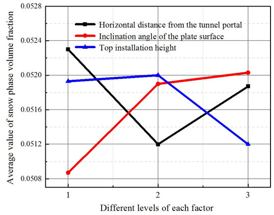
To more intuitively illustrate how the snow phase volume fraction varies with different levels of each key factor, Figure 16 presents the range analysis diagram with the snow phase volume fraction as the target index. Synthesizing the range analysis results, analysis of variance, and comprehensive evaluation of snow prevention efficacy, the optimal parameter combination for the wind deflector is recommended as follows: horizontal distance from the tunnel portal L = 6 m, plate inclination angle β = 60°, and top installation height h = 2 m. Under this combined working condition, the calculation result of the snow phase volume fraction at 35 m from the tunnel portal is 0.0505. Compared with other working conditions, this combination can more effectively reduce the snow phase volume fraction at this position, inhibit snow accumulation, and thereby mitigate the impact of wind-blown snow disasters on the tunnel portal. On the windward side, this combination can fully increase the wind speed, form a stable accelerated air flow, effectively enhance the transport capacity of snow particles, and enable them to quickly cross the tunnel portal area. On the leeward side, the wind speed is also reasonably increased, the area of the low-speed zone is significantly reduced, the deposition of snow particles is effectively reduced, and the high-concentration snow accumulation area is significantly shifted to the leeward side, and its range is significantly reduced. Compared with the working condition without wind deflector, the snow volume fraction in the area in front of the tunnel portal is reduced by 12.3%, the maximum accumulation position is moved back about 25 m, and the high-value area (>0.06) disappears completely. This indicates that the optimal combination can significantly improve the wind field structure in the tunnel portal area, effectively regulate the migration path and deposition position of snow particles, and has a good prevention and control effect on wind-blown snow disasters.
Figure 16.
Range analysis diagram with snow phase volume fraction as the target factor.
5. Conclusions
Through in-depth analysis of wind deflector configuration parameters for wind-blown snow prevention at tunnel portals in Central Asian alpine mountains, this study clarifies the influence laws of key parameters on prevention efficacy and identifies the optimal parameter combination. The main conclusions are summarized as follows:
- (1)
- Combined with the wind-snow environment of the tunnel portal along the China-Tajikistan Highway Phase II Project, the wind deflector is installed in the upper area on the windward side of the tunnel entrance, with its plate body parallel to the tunnel cross-section to cover the main wind flow channel. Three core control parameters are determined: top installation height (h), plate inclination angle (β), and horizontal distance from the tunnel portal (L). The incoming wind speed is set to 12.75 m/s (corresponding to the 50-year return period basic wind speed in the study area), with parameter value ranges defined as h = 1.5–2.5 m, β = 60–80°, and L = 4–10 m, laying a solid foundation for subsequent simulation analysis.
- (2)
- Single-factor numerical simulation analysis reveals the influence laws of each parameter on wind field characteristics and snow accumulation. For the horizontal distance from the tunnel portal (L), the optimal value is 6 m—at this distance, the disturbance zone precisely covers the main wind flow development area in front of the portal, effectively lifting the main incoming flow path, compressing the recirculation zone (reducing its length from 45.8 m to 22.3 m), reducing snow particle settlement, and achieving the best comprehensive prevention effect. Excessively small (4 m) or large (8 m, 10 m) distances lead to insufficient disturbance development or ineffective intervention, respectively. For the plate inclination angle (β), 60° is the optimal layout angle—it significantly increases leeward wind speeds (rising from below 10 m/s to 10–12 m/s), promotes snow particle transport, and minimizes accumulation risk. As the angle increases to 65–80°, windward speeds continue to rise, but leeward speed gains are insufficient, weakening snow accumulation control efficacy. For the top installation height (h), 2.00 m delivers optimal performance, with significant wind speed improvement on both windward and leeward sides, and minimal snow accumulation risk. Beyond this height, marginal efficiency gains diminish, and the snow accumulation control effect approaches saturation.
- (3)
- Considering the interaction and nonlinear coupling relationships among the three parameters, an L9(33) orthogonal test design is adopted, with the snow phase volume fraction at 35 m on the leeward side of the tunnel portal as the core evaluation index. Range analysis and analysis of variance results indicate that the influence degree of each parameter on snow prevention efficacy follows the order: horizontal distance from the tunnel portal (RA = 0.00143, F = 15.2) > top installation height (RC = 0.00083, F = 4.0) > plate inclination angle (RB = 0.00080, F = 3.9). The horizontal distance is identified as the statistically significant dominant factor (95% confidence level) affecting the snow prevention efficacy. The optimal parameter combination determined by the orthogonal test is L = 6 m, β = 60°, and h = 2 m. Under this combination, the snow phase volume fraction at 35 m from the tunnel portal is 0.0505, which is 12.3% lower than that without a wind deflector; the high-concentration snow accumulation zone shifts 25 m leeward, and the high-value area of snow phase volume fraction disappears completely, effectively alleviating the impact of wind-blown snow disasters on the normal operation of tunnel portals.
- (4)
- The limitations of this study are as follows: first, the snow particles are simplified as monodisperse spherical particles, ignoring the influence of particle size variability on transport and deposition processes; second, the model does not consider snow melting, hardening, and compaction, focusing only on the instantaneous transport and deposition of wind-blown snow; third, the wind-snow flow direction is assumed to be perpendicular to the tunnel portal, without considering the impact of wind direction deviation in actual conditions; fourth, the wind deflector is simplified as a zero-thickness thin plate, ignoring the influence of snow accumulation on the deflector itself and structural deformation; fifth, due to the limitations of on-site measurement conditions, the numerical model has not been verified by field test data, and the simulation results need to be further confirmed by practical engineering applications.
- (5)
- In terms of practical applications, the optimal parameter combination (L = 6 m, β = 60°, h = 2 m) proposed in this study can be directly applied to the wind-blown snow prevention project of the China-Tajikistan Highway Phase II Project tunnel portals and similar alpine mountain tunnel projects. During construction, attention should be paid to the structural stability and installation accuracy of the wind deflector, and anti-snow accumulation surface treatment or snow removal devices can be adopted to enhance the long-term service performance of the deflector. Future research can focus on the following directions: introducing multi-disperse snow particle systems to refine the simulation of snow particle transport and deposition; combining thermodynamic models to consider the influence of snow melting and hardening on accumulation effects; exploring the prevention efficacy of wind deflectors under different wind direction deviations; conducting on-site measurement and verification of the optimal parameter combination to improve the reliability of the research results; and studying the combined prevention effect of wind deflectors with other protective measures (such as snow storage platforms and snow fences) to form a more comprehensive wind-blown snow disaster prevention system.
Author Contributions
Conceptualization, B.Z. and X.X.; methodology, C.L.; software, A.J.; resources, data curation, X.X.; writing—original draft preparation, B.Z. and X.X.; writing—review and editing, C, L. and Z.S.; visualization, A.J.; supervision, Z.S. All authors have read and agreed to the published version of the manuscript.
Funding
This research was funded by the Shaanxi Provincial Innovation Capacity Support Program—Innovation Team (Grant No. 2020TD-005) and the 2023 Key Science and Technology Project of China Road and Bridge Engineering Co., Ltd. (Grant No. 2023-zlkj-03).
Data Availability Statement
Data are contained within the article.
Conflicts of Interest
Authors Bin Zhi and Changwei Li were employed by the company China Road and Bridge Engineering Co., Ltd. The remaining authors declare that the research was conducted in the absence of any commercial or financial relationships that could be construed as a potential conflict of interest.
References
- Zhi, B.; Li, C.; Guo, Z. Analysis of Temperature Field Distribution Characteristics and Influencing Factors of Tunnels in Seasonal Frozen Areas. In Proceedings of the 2024 6th International Conference on Hydraulic, Civil and Construction Engineering (HCCE 2024), Guangzhou, China, 13–15 December 2024; Atlantis Press: Dordrecht, The Netherlands, 2025; pp. 775–783. [Google Scholar]
- Liu, N.; Li, N.; Xu, C.; Li, G.; Song, Z.; Yang, M. Mechanism of secondary lining cracking and its simulation for the dugongling tunnel. Rock Mech. Rock Eng. 2020, 53, 4539–4558. [Google Scholar] [CrossRef] [Scilit]
- Zhang, G.; Zhang, Q.; Mo, H.; Zhao, Y.; Zhi, X.; Fan, F. Numerical Investigations of Snowdrift Characteristics on Roofs with Consideration of Snow Crystal Morphological Features. Buildings 2025, 15, 3606. [Google Scholar] [CrossRef] [Scilit]
- Wang, J.; Zhang, J.; Xie, F.; Zhang, Y.; Gao, G. A study of snow accumulating on the bogie and the effects of deflectors on the deicing performance in the bogie region of a high-speed train. Cold Reg. Sci. Technol. 2018, 148, 121–130. [Google Scholar] [CrossRef] [Scilit]
- Tsybulnyk, S. Protection of Buildings and Engineering Structures from the Effects of Wind and Snow Loads. In Advanced System Development Technologies II; Springer Nature: Cham, Switzerland, 2025; pp. 303–351. [Google Scholar]
- Anno, Y. Snow deflector built at the edge of a road cut. Cold Reg. Sci. Technol. 1986, 12, 121–129. [Google Scholar] [CrossRef] [Scilit]
- Gao, G.; Chen, Q.; Zhang, J.; Zhang, Y.; Tian, Z.; Jiang, C. Numerical study on the anti-snow performance of deflectors on a high-speed train bogie frame. J. Appl. Fluid Mech. 2020, 13, 1377–1389. [Google Scholar] [CrossRef] [Scilit]
- Lei, J.; Cheng, J.; Gao, L.; Ma, B.; An, Y.; Dong, H. Characteristics of snow cover distribution along railway subgrade and the protective effect of snow fences. J. Arid. Land 2023, 15, 901–919. [Google Scholar] [CrossRef] [Scilit]
- Yu, H.; Li, G.; Walter, B.; Lehning, M.; Zhang, J.; Huang, N. Wind conditions for snow cornice formation in a wind tunnel. Cryosphere 2023, 17, 639–651. [Google Scholar] [CrossRef] [Scilit]
- Qiu, S.; Bai, M.; Lin, D.; Xia, H.; Tang, Z. Study on the Evolution Process of Snow Cover in Wind-Induced Railway Embankments and the Control Effect of Snow Fences. Appl. Sci. 2025, 15, 6057. [Google Scholar] [CrossRef] [Scilit]
- Cao, R.; Yu, Z.; Liu, Z.; Chen, X.; Zhu, F. An investigation of snow drifting on low-sloped gable roofs: Wind-tunnel tests and CFD simulations. Cold Reg. Sci. Technol. 2021, 183, 103227. [Google Scholar] [CrossRef] [Scilit]
- Li, P.; Bai, M.; Ding, L.; Cui, Z.; Zhang, Z. Field measurement and outdoor wind tunnel test of snow-drifting: Snow distribution characteristics of railway subgrade and deposition mechanism. J. Wind Eng. Ind. Aerodyn. 2022, 230, 105197. [Google Scholar] [CrossRef] [Scilit]
- Ji, W.G.; Shon, S.; Seo, S.H.; Kim, B.; Kim, K. Snow accretion on a model train: Climate wind tunnel experiments. J. Wind Eng. Ind. Aerodyn. 2023, 242, 105572. [Google Scholar] [CrossRef] [Scilit]
- Walter, B.; Weigel, H.; Wahl, S.; Löwe, H. Wind tunnel experiments to quantify the effect of aeolian snow transport on the surface snow microstructure. Cryosphere 2024, 18, 3633–3652. [Google Scholar] [CrossRef] [Scilit]
- Zhang, Y.; Wang, J.; Jiang, C.; Zhang, J.; Wang, T.; Gao, G. Investigation of ice and snow accumulations on the bogie areas of high-speed trains using ice wind tunnel experiments. Cold Reg. Sci. Technol. 2022, 199, 103560. [Google Scholar] [CrossRef] [Scilit]
- Zhao, C.; Wang, T.; Zhou, G.; Wang, Y.; Feng, Y.; Jiang, C.; Song, Z.; Li, H. Wind tunnel experimental investigation on the performance of the ice-melting system for high-speed train bogies. Transp. Saf. Environ. 2025, 7, tdae022. [Google Scholar] [CrossRef] [Scilit]
- Shaw, D.L. Living Snow Fences: Protection that Just Keeps Growing; Colorado Interagency Living Snow Fence Program, Colorado State University: Fort Collins, CO, USA, 1989. [Google Scholar]
- Tabler, R.D. Snow Fence Guide; Strategic Highway Research Program, National Research Council: Washington, DC, USA, 1991. [Google Scholar]
- Tabler, R.D. Controlling Blowing and Drifting Snow with Snow Fences and Road Design; Transportation Research Board (TRB): Washington, DC, USA, 2003. [Google Scholar]
- Basnet, K.; Constantinescu, G.; Muste, M.; Ho, H. Method to assess efficiency and improve design of snow fences. J. Eng. Mech. 2015, 141, 4014136. [Google Scholar] [CrossRef] [Scilit]
- Wang, L.; Huang, R. Application of New Wind Guides for Natural Snow Removal. Qinghai Transp. Sci. Technol. 2010, 22, 188–190. [Google Scholar]
- Yang, Z.; Du, B. Prevention and control of highway wind blown snow diseases. Highway 2012, 57, 247–249. [Google Scholar]
- Constantinescu, G.; Muste, M.; Basnet, K. Optimization of Snow Drifting Mitigation and Control Methods for IOWA Conditions; The Iowa Highway Research Board Iowa Department of Transportation and The Federal Highway Administration: Ames, IA, USA, 2015.
- Du, S.; Petrie, J.; Shi, X. Use of snow fences to reduce the impacts of snowdrifts on highways: Renewed perspective. Transp. Res. Rec. 2017, 2613, 45–51. [Google Scholar] [CrossRef] [Scilit]
- Wu, P. Application of New Wind Guides for Natural Snow Removal. TWestern China Commun. Sci. Technol. 2019, 6, 54–57. [Google Scholar] [CrossRef]
- Li, F. Application of New Wind Guides for Natural Snow Removal. Shijiazhuang Tiedao Univ. 2021. [Google Scholar] [CrossRef]
- Ma, L.; Liu, J.; Ran, W.; Hu, Z.; Li, Z.; Yu, X. Wind tunnel experimental study on shed tunnels to prevent andcontrol blowing snow on highways. J. Glaciol. Geocryol. 2022, 44, 726–734. [Google Scholar] [CrossRef]
- Chen, Y.; Li, X.; Yang, C. Optimization and Study of Snow Platform in Leeward Half-Cut of Highway. Highway 2023, 68, 305–310. [Google Scholar]
- Tominaga, Y.; Okaze, T.; Mochida, A. CFD Modeling of Snowdrift around a Building: An Overview of Models and Evaluation of a New Approach. Build. Environ. 2011, 46, 899–910. [Google Scholar] [CrossRef] [Scilit]


Disclaimer/Publisher’s Note: The statements, opinions and data contained in all publications are solely those of the individual author(s) and contributor(s) and not of MDPI and/or the editor(s). MDPI and/or the editor(s) disclaim responsibility for any injury to people or property resulting from any ideas, methods, instructions or products referred to in the content. |
© 2026 by the authors. Licensee MDPI, Basel, Switzerland. This article is an open access article distributed under the terms and conditions of the Creative Commons Attribution (CC BY) license.