


Abstract
The steel-plate–concrete composite reinforcement method is derived from the bonded steel plate and increased-section techniques. It is employed to enhance the strength of concrete structures that require a substantial increase in load-bearing capacity. To develop a flexural deformation calculation theory that accounts for slip effects in general reinforced cross-sections with bilateral symmetry, interfacial slip and deflection equations are formulated based on the relationship between interlayer slip and the rotational angle of beams in the plane, as well as the principle of force equilibrium. A numerical method, established based on this theoretical framework, is proposed to facilitate the analytical solution and is verified to be consistent with analytical results. Furthermore, the accuracy of the calculation theory is validated through bending experiments. Finally, the influence of key parameters affecting slip on the flexural stiffness of the reinforced beam is evaluated by determining the stiffness reduction coefficient according to the theory. The results indicate that the flexural stiffness of reinforced beams is governed by three non-dimensional parameters: the boundary condition parameter (μ), composite action parameter (shear connector stiffness (βl)), and relative bending stiffness parameter (G∞/G0). The loading mode does not affect the flexural stiffness of the reinforced beams. As βl approaches 100 and G∞/G0 approaches 1, η approaches 100%. In cases where high stiffness is required, reducing interfacial slip can minimize the loss of flexural stiffness in composite structures. Conservative calculations indicate that satisfying the conditions βl ≥ 8 and G∞/G0 ≤ 1.6 during design can ensure that the reduction in flexural stiffness of the reinforced beam remains above 90%.
1. Introduction
The steel-plate–concrete composite reinforcement method involves installing reinforcing bars on the concrete surface, pre-welding studs to the inner surface of the steel plate, and injecting high-strength grouting material between the concrete and the steel plate. Through the combined action of the studs and grout, structural loads from the existing concrete are effectively transferred to the reinforcing steel plate, thereby optimizing internal force distribution. As a result, the overall structural stiffness is significantly enhanced, and cracking in the concrete tensile zone is effectively suppressed. Compared with commonly used strengthening methods, such as FRP reinforcement [1,2,3], concrete jacketing [4], and prestressed reinforcement [5], the steel-plate–concrete composite approach offers several advantages. FRP reinforcement is often constrained by environmental conditions and cost, whereas concrete jacketing and prestressed reinforcement can be difficult to implement on site. In summary, the steel-plate–concrete composite method integrates the advantages of the steel plate bonding technique [6,7,8] and the section enlargement method [9,10,11], enabling relatively simple construction at low cost while providing substantial improvements in structural stiffness. Consequently, this method is particularly suitable for practical engineering applications where conventional reinforcement techniques are insufficient, especially in cases requiring enhanced or specialized load-bearing capacity [12,13].
Several researchers have investigated structural calculation methods for steel-plate–concrete composite reinforcements. Wang et al. [14] and Shi et al. [15] performed flexural experiments on three-sided, horseshoe-shaped, T-section composite-reinforced beams after damage and proposed a formula for calculating the flexural bearing capacity of ideally reinforced sections. However, this formula does not account for slip between the old and new concrete, or between the steel plate and the concrete. Finite element analyses by Wang revealed that the load–displacement response of models neglecting slip deviated from experimental results. Similarly, the effect of slip was confirmed in flexural experiments by Taniguchi et al. [16] (three-sided reinforcement) and Lin et al. [17] (four-sided reinforcement) on steel-plate–concrete composite structures. Overall, current theories on composite steel plate reinforcement do not adequately consider interfacial slip, leading to insufficiently accurate calculation results. Therefore, the development of a theory of composite steel plate reinforcement that considers slip effects could help promote further progress in this area.
Numerous studies have investigated methods for calculating slip at the bonding interfaces of steel–concrete composite structures subjected to flexural deformation. Representative works include those by Gihammar, Gopu, and Pan [18,19], who applied the principles of force equilibrium, deformation compatibility, and minimum potential energy to derive the differential equation for bending in T-shaped composite beams, incorporating slip effects based on Newmark’s linear relationship between slip force and displacement. Nie et al. [20] developed an additional deflection formula considering slip in steel–concrete composite beams under various loading conditions. By simplifying and modifying the theoretical formula, they proposed a general expression for deflection in composite beams with partial shear connection, accounting for slip. Furthermore, based on experimental results, they introduced a reduced stiffness method for deflection calculation [21]. The accuracy of these theoretical methods has been validated through experiments on T-shaped composite beams (single-layer composites). However, for structural members primarily subjected to compression or combined compression and bending—such as columns or arch ribs—single-sided reinforcement introduces significant eccentricity, and interfacial slip can lead to more pronounced losses in overall stiffness. In such cases, multi-surface reinforcement schemes offer clear advantages by effectively reducing eccentricity. Therefore, further investigation of flexural calculation theories for multi-surface reinforcement is both necessary and meaningful, as it can provide valuable guidance for practical engineering strengthening applications.
This paper develops a flexural deformation theory for bilaterally symmetric general cross-sections reinforced with steel-plate–concrete composites, incorporating the effect of slip at the bonding interface, based on the Euler–Bernoulli beam theory. General equations for interface slip and deflection are derived from this theoretical framework. To address the complexity of the analytical solutions, a numerical method is introduced. Comparisons between the analytical and numerical solutions under specified boundary conditions demonstrate their consistency. The validity of the proposed theory is further confirmed through bending experiments. Additionally, the influence of key parameters affecting slip on the flexural stiffness of the reinforced beam is examined by deriving a stiffness reduction coefficient from the theory.
2. Calculation Theory
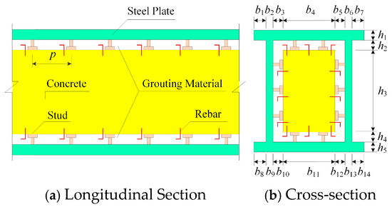
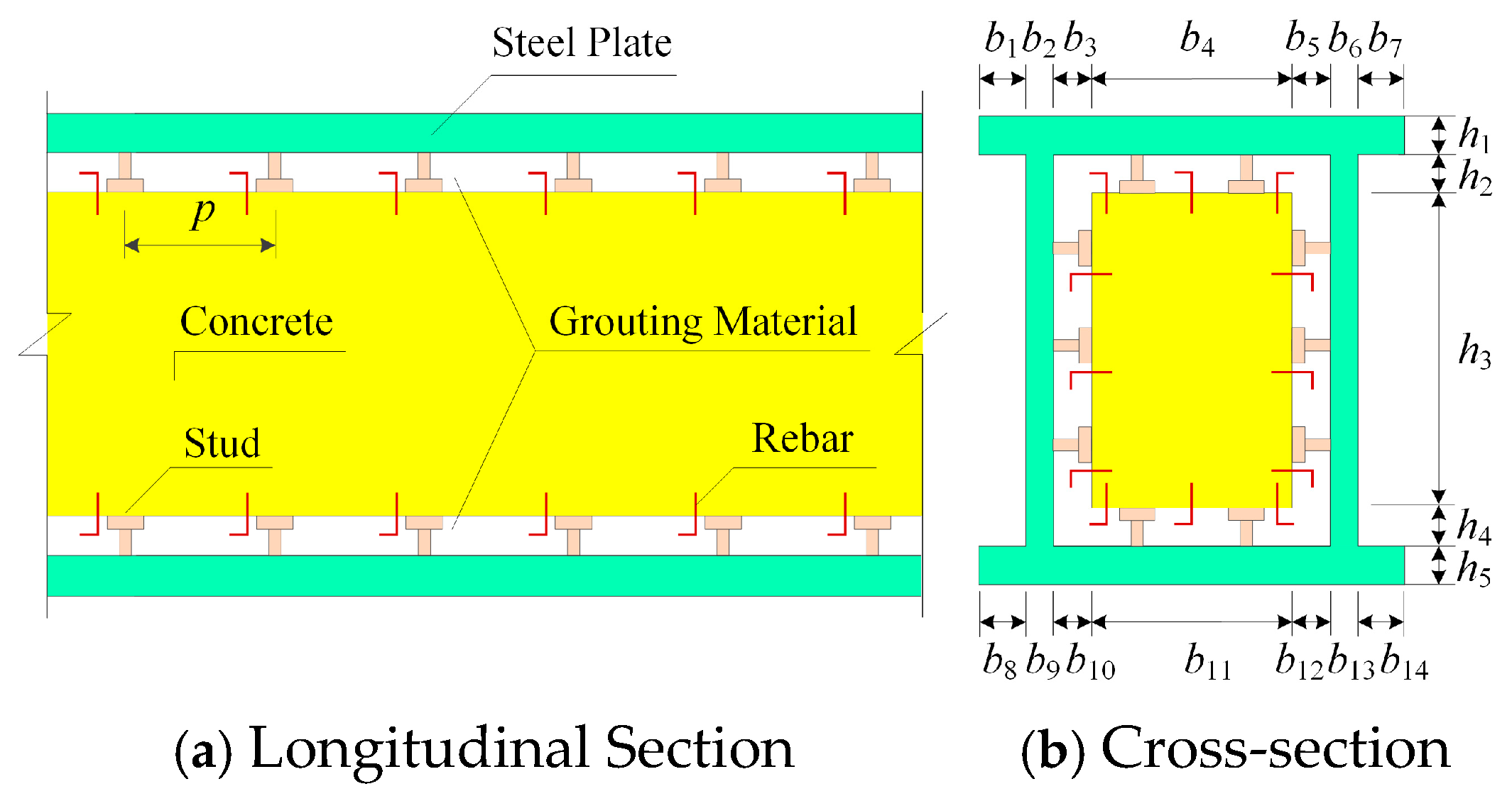
Figure 1 illustrates the steel-plate–concrete composite reinforcement structure, which consists of existing concrete beams, implanted rebars, high-strength grouting materials, and reinforced steel plates with shear nails on the inner side. In the figure, p denotes the length direction distance of the shear stud, and hi and bi represent the size of each part in the height and width directions of the section, respectively. According to experimental results [17], slip primarily occurs between the steel plate and grouting material, whereas the slip between the grouting material and concrete interface before structural failure can be disregarded. Although variations in grout properties over time and temperature may affect interface strength [22,23], the experimental results indicate that cracking in the grout occurred at early stages of loading, implying that interface strength was primarily provided by the shear studs. Therefore, potential changes in grout material properties are neglected in this study. Accordingly, the following assumptions are adopted:
Figure 1.
Reinforcement Beam Structure.
- (1)
- The material exhibits linear elasticity, with a linear relationship between the sliding displacement and sliding shear between the steel plate and the grouting material.
- (2)
- The calculation theory of small deformations is applicable, where every part of the same cross-section has an equal vertical deformation.
- (3)
- The internal concrete (including the grouting material) and the reinforced steel structure satisfy the plane section assumption, with slip occurring at the interface between the two structures. The adhesion between the steel plate and grouting material is neglected, and slip stiffness is provided by the shear studs.
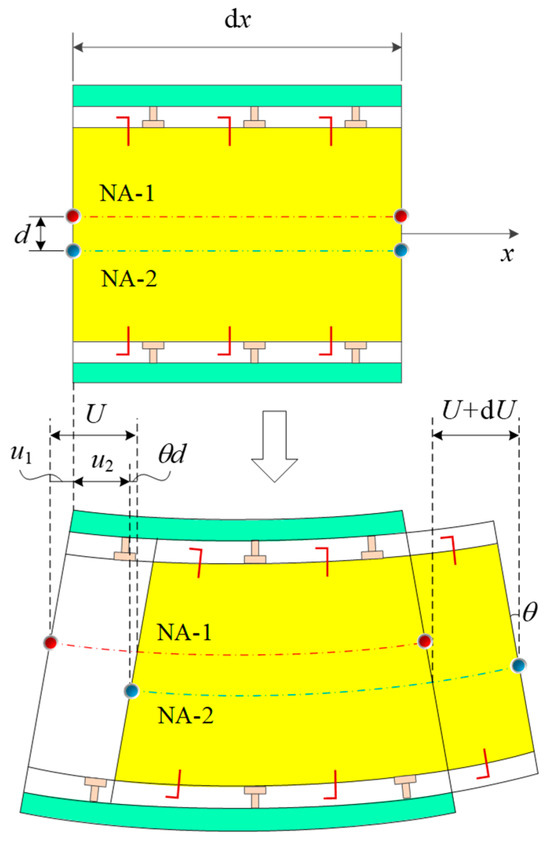
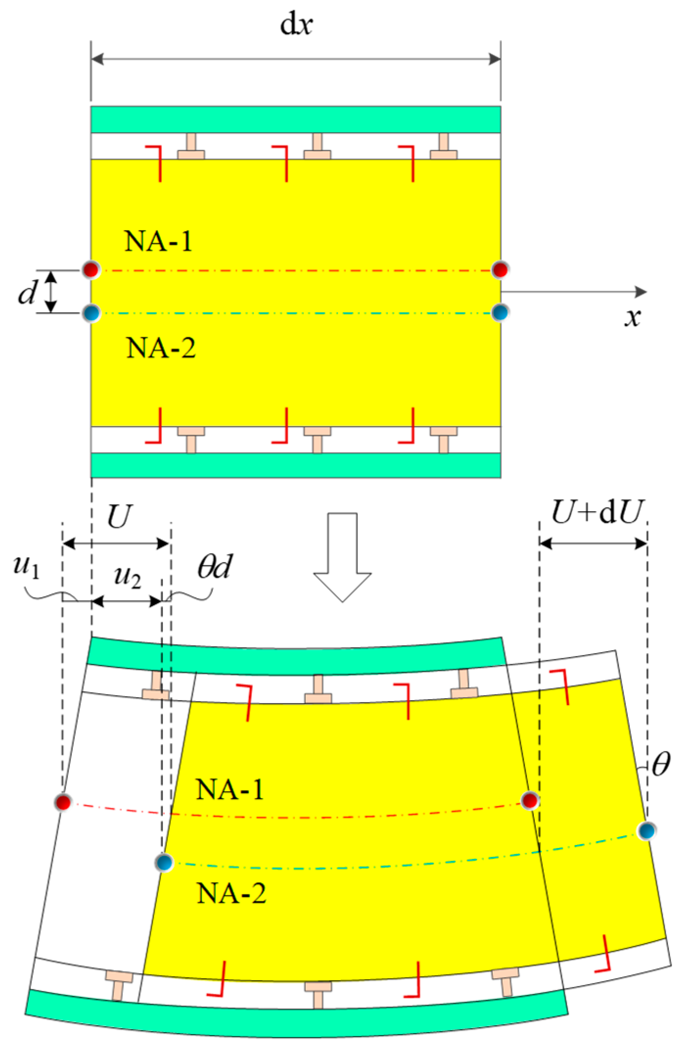
Under these assumptions, no relative vertical displacement exists between the steel plate, grouting material, and internal concrete, and only the relative longitudinal slip between the steel plate and grouting material is considered. Figure 2 illustrates the relationship between the interlayer slip and rotary angle during beam deformation. In the figure, subscripts “1” and “2” represent the steel plate and internal concrete containing the grouting material, respectively. NA denotes the neutral axis of the element, and u represents the displacement of the element in the axial x-direction. θ represents the rotary angle of the section, and it remains the same for the entire cross-section because no vertical relative displacement occurs. d denotes the centroid distance between the steel plate and the internal concrete containing the grouting material, with a negative value when the centroid of the steel plate is above. U represents the relative amount of slip in the x-direction between the steel plate and the concrete.
Figure 2.
Deformation of Micro-segmented Beam Structure.
According to the deformation relationship, the relationship between the interlayer slip and rotary angle can be represented as
Moreover, the physical relationship of the beam is determined as
where ′ indicates the derivation of the function, N and M represent the axial force and bending moment, respectively, w denotes the deflection, E denotes the elastic modulus, A represents the cross-sectional area, and I indicates the moment of inertia.
Differentiating Equation (1) and substituting the geometric relationship () into Equations (2) and (3) yield the relationship between the internal force and the relative slip displacement (U) of the interface:
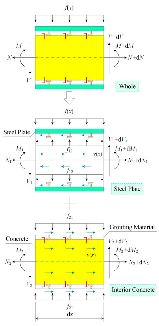
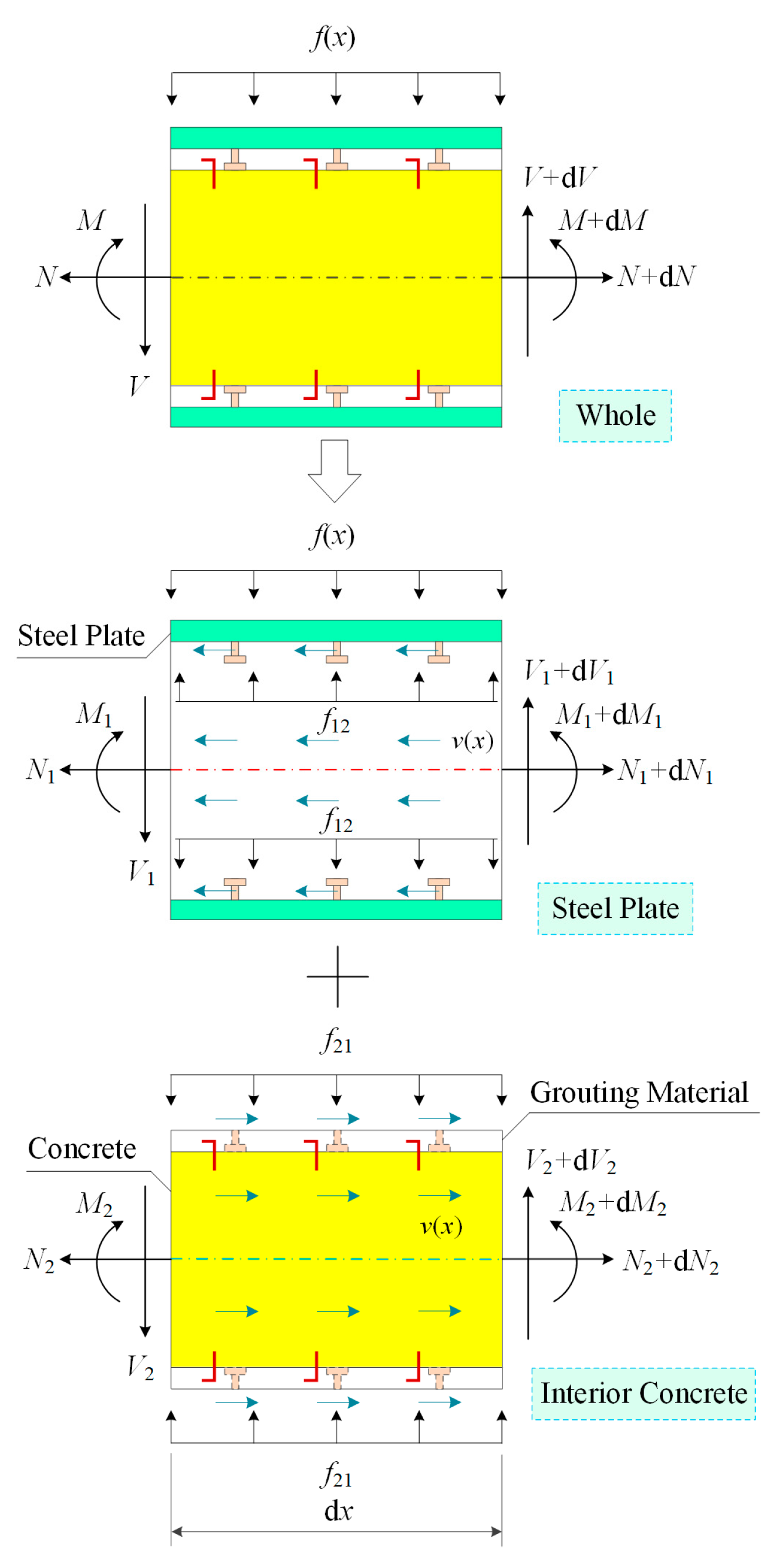
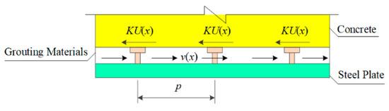
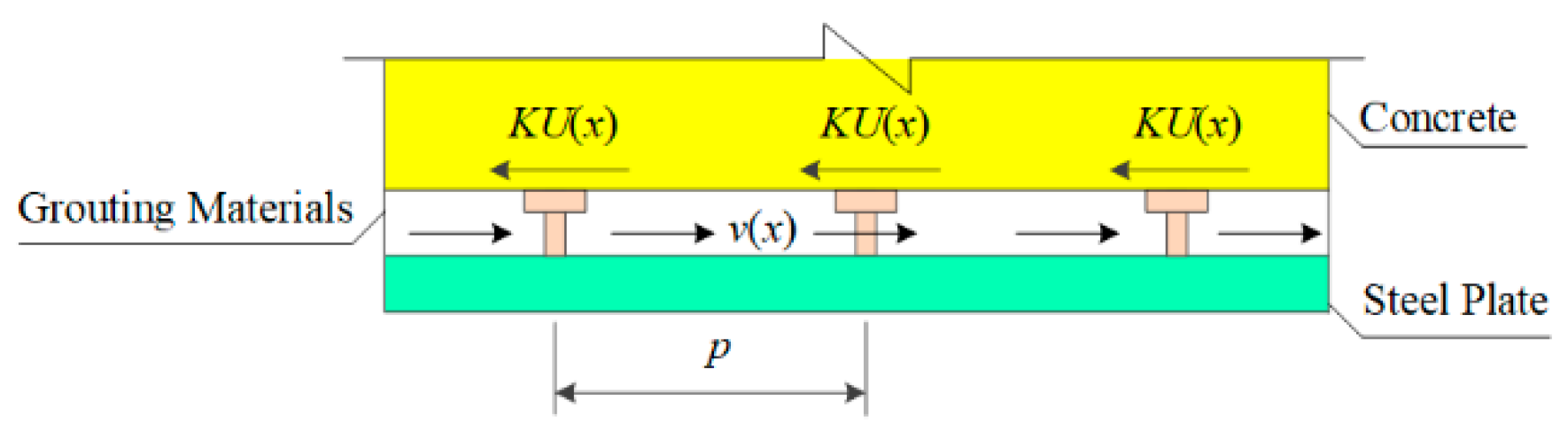
Equation (4) provides a balance relationship for the section, from which we can obtain the axial force (N) and bending moment (M). To illustrate this, Figure 3 and Figure 4 depict the longitudinal sectional force state of the reinforced beam microsegment under the influence of the load (f(x)) and force state of the shear studs in the longitudinal direction, respectively. In the figures, V represents the shear force, fij(x) denotes the uplift force of the interface, with the “ij” subscript indicating the direction of force transmission from j to i, and v(x) represents the sliding shear force per unit length of the interface. Using the balance relationship, we obtain
where n is the number of shear stud columns in the longitudinal direction and K is the shear stiffness of the studs in that direction.
Figure 3.
Internal Forces of Longitudinal Micro Units.
Figure 4.
Longitudinal Forces for Shear Studs.
Subsequently, after differentiating Equation (4) and substituting the balance relationship into Equations (5)–(7), we obtain
where G0 and G∞ represent the bending stiffness of the laminated beams without considering the bonding stiffness and the composite beams with rigid bonding surfaces, respectively.
Thus, the constant-coefficient differential equation for the interface slip displacement is obtained by further simplifying Equation (8):
where parameters α and β can be, respectively, represented as
The relational expressions for the deflection (w) and strain (ε) in the longitudinal direction can be obtained based on the relationship between force and deformation. Finally, the expression is given as
where represents the deflection of the rigid bonding surface, is the additional deflection caused by the slip, and y is the vertical distance from the calculated location of the section stress to the neutral axis. Parameters γ and δ are defined as follows:
3. Comparison and Verification
3.1. Comparison of Theory and Numerical Method
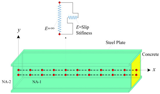
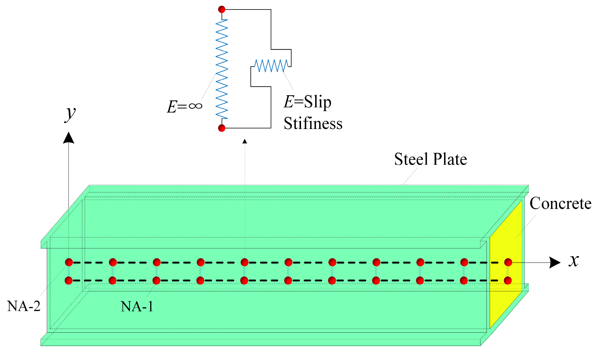
To simplify the complex theoretical analysis, a two-dimensional numerical method based on the proposed calculation theory is introduced. Figure 5 illustrates the fundamental principle of this method. The model is developed using the open-source finite element software OpenSees (Version:3.3.0), with the x- and y-axes representing the global coordinate system. The materials of the reinforced beam, including concrete (with grouting material) and steel plates, are modeled as elastic beam elements with nodes positioned at the neutral axis. To account for slip effects, springs are placed between the steel plate and concrete in both the x- and y-directions. The axial springs in the y-direction are assigned infinite stiffness, while the shear spring in the x-direction, which represents slip stiffness, is set equal to the shear connection stiffness of the bonding interface.
Figure 5.
Two-dimensional Numerical Method.
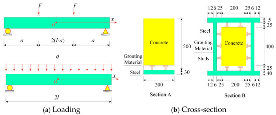
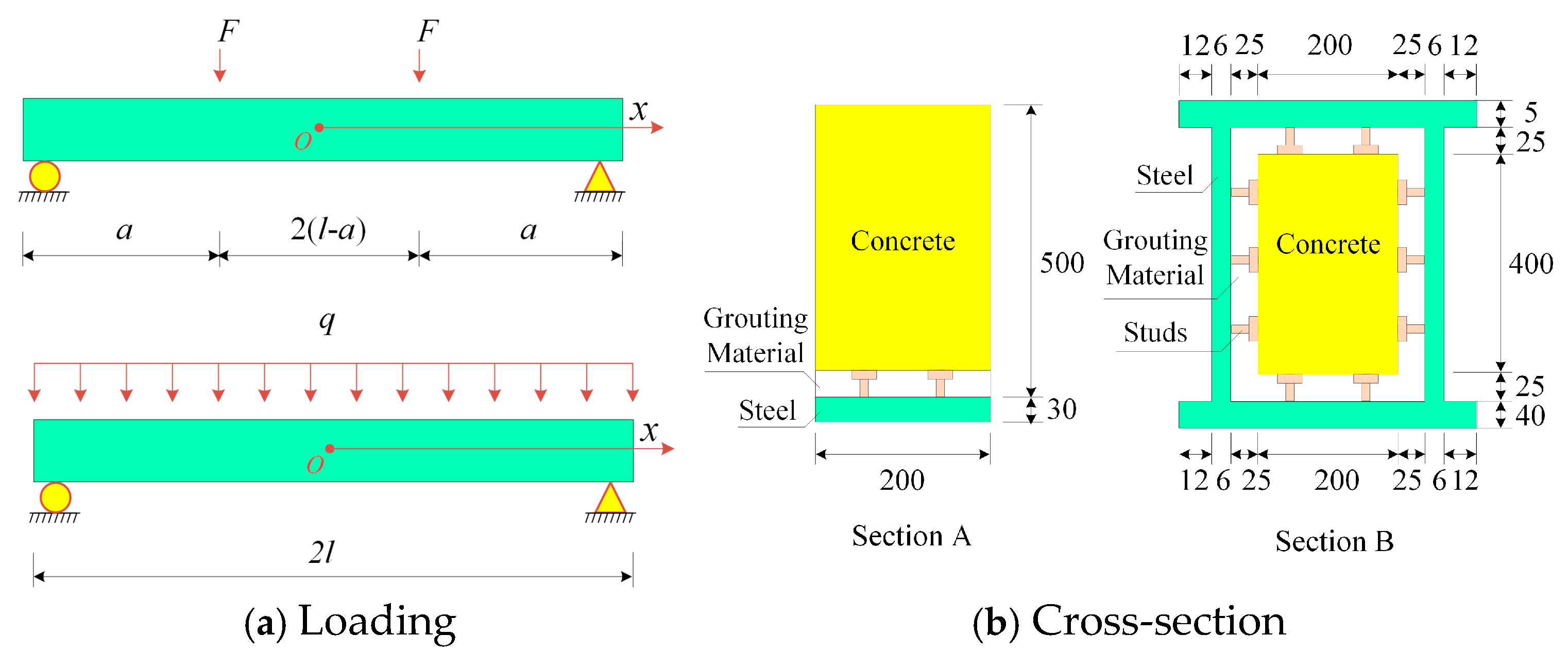
To assess the adaptability and precision of the deflection (Equation (13) and strain Equation (14)) under varying reinforcement conditions, theoretical analytical formulas were determined for simply supported reinforced beams with different reinforcements subjected to even loading and two-point loading conditions, as depicted in Figure 6. These equations were used to compare the results with those obtained from the numerical method. Here, F represents the point load, q indicates the density of the even load, a represents the distance from the point load to the bracket, and l is half of the beam length. The internal concrete and grouting material were modeled using the equivalent stiffness-transformed section parameters. The parameters of the reinforcement sections are listed in Table 1.
Figure 6.
Numerical Examples of Reinforced Beams (unit: mm).
Table 1.
Material and Geometrical Parameters Used in the Calculation.
The deflection and strain analytical formulas for simply supported beams under two-point loading were derived by substituting the boundary conditions of the beam interface slip displacement (U) and the continuous condition of deflection (w). The expressions for deflection and strain can be solved as follows:
Similarly, the expression under even loading can be obtained as follows:
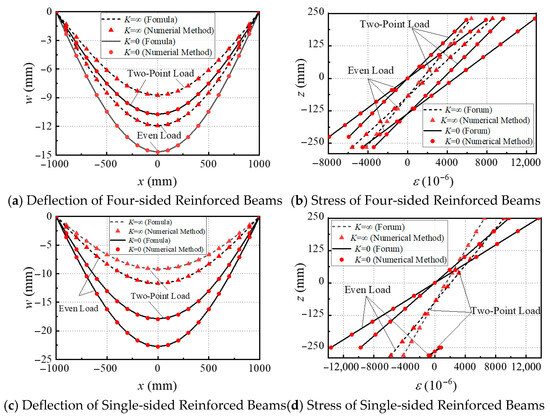
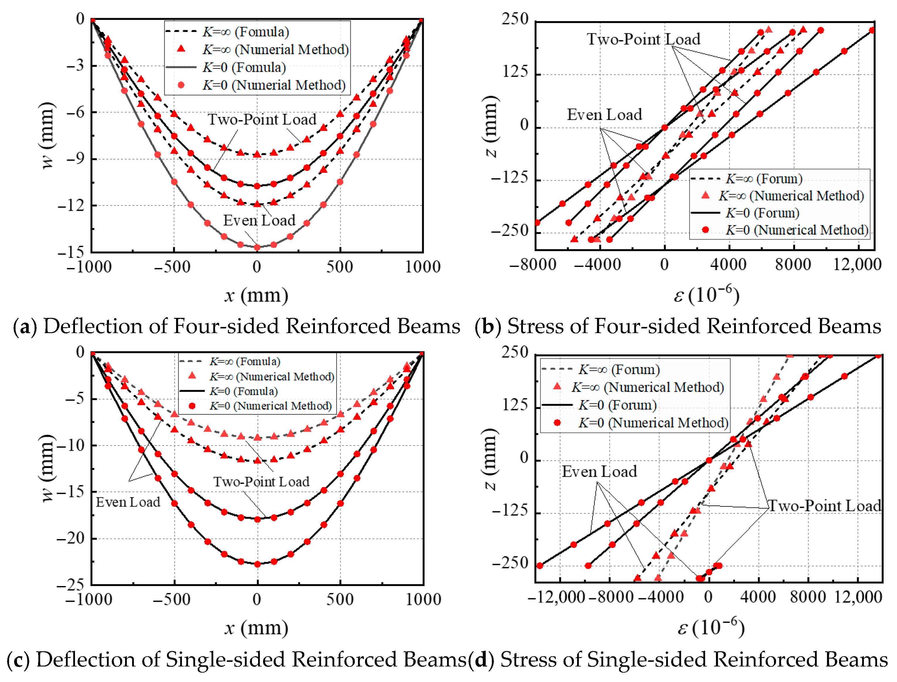
Figure 7 shows a comparison of the deflection and strain calculation results for the four- and single-sided reinforcements, including two extreme cases—complete bonding and full slip of the bonding surface—using analytical formulas and the numerical method. The results indicate that utilizing four-sided and single-sided reinforcements nearly doubles the deflection and strain results of the theoretical and numerical methods, with the maximum deviation of the deflection and stress being less than 1%. These findings suggest that the theoretical formulas for the four- and single-sided reinforcements are consistent with the numerical simulation results. Furthermore, these comparison results can be inferred to hold true for the three-sided reinforcement.
Figure 7.
Comparison of Deflection and Stress Analytical Formulas with Numerical Method for Four-Sided and Single-Sided Reinforced Beams.
3.2. Experimental Verification
Push-out and bending experiments were conducted to evaluate the accuracy of the calculation theory and to validate the theoretical predictions. The push-out experiments measured the lateral stiffness of the shear studs, while the bending tests assessed the flexural deformation of the reinforced beams.
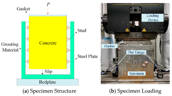
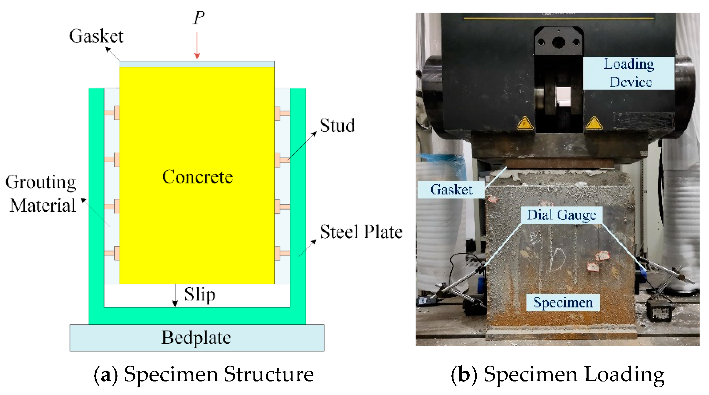
Unlike typical composite structures, steel-plate–concrete composite reinforcement requires that shear studs be embedded less deeply in the concrete to minimize damage to the existing concrete. Consequently, the lateral stiffness of the shear studs must be determined through push-out experiments. Figure 8 illustrates the push-out test, which was performed under monotonic static loading using a High-performance testing machine (INSTRON-Division of ITW Ltd., High Wycombe, UK) on shear stud connector specimens [17]. The figure shows a groove-shaped steel plate with shear studs welded on both sides, bonded to the concrete with grouting material, and a gap between the bottom of the steel plate and the bottom of the concrete to allow for sliding.
Figure 8.
Shear Experiment of Bonding Surface.
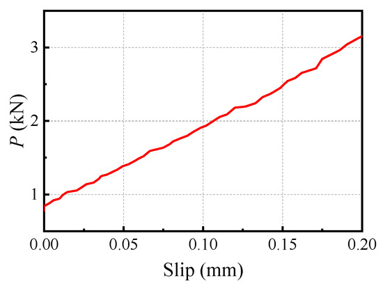
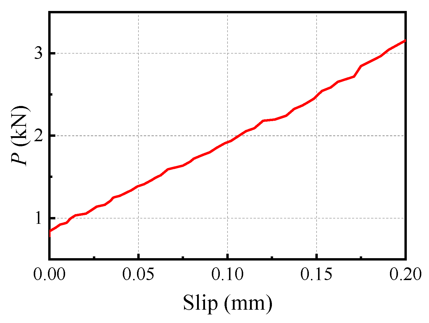
The lateral stiffness of the shear studs, shown by the experimental results of the elastic segment in Figure 9, was 11.86 kN/mm.
Figure 9.
Load–Slip Curve of Shear Studs.
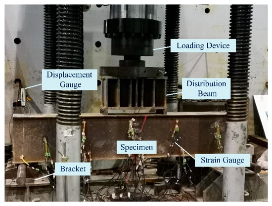
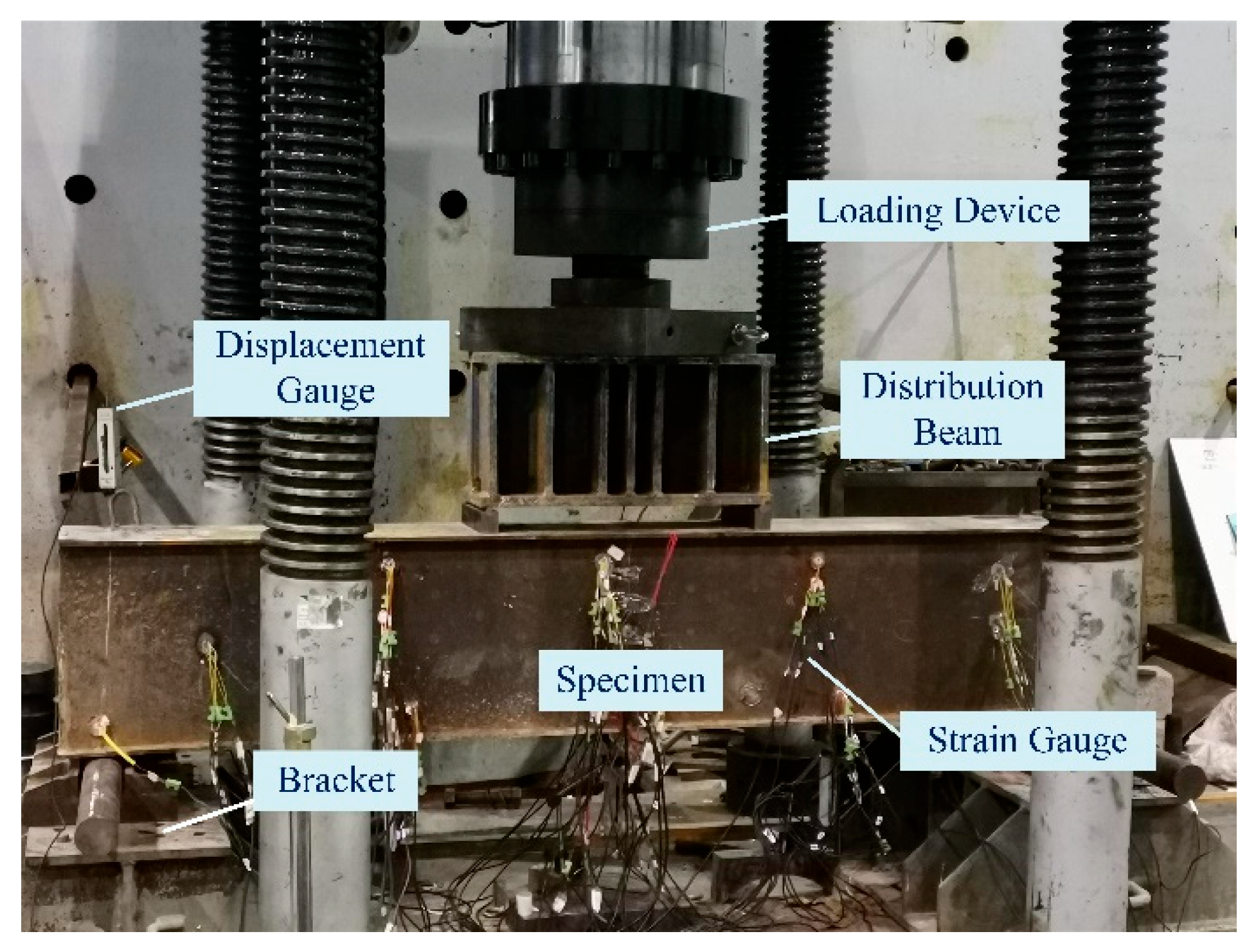
The deflection and strain formulas for the reinforced structure, which incorporate the measured lateral stiffness (K), were further validated through a bending experiment on a simply supported reinforced beam. The test was conducted using a YAW-10000F microcomputer-controlled electro-hydraulic servo testing machine (Bangwei Electromechanical Control Engineering Co., Ltd., Hangzhou, China), as shown in Figure 10. The specimen shown in the figure was reinforced by chiseling, implanting rebars, and attaching four-sided steel plates welded with shear studs. A grouting material was applied to enhance the bonding strength between the concrete and steel plates.
Figure 10.
Bending Experiment of Reinforcement Beam.
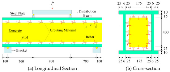
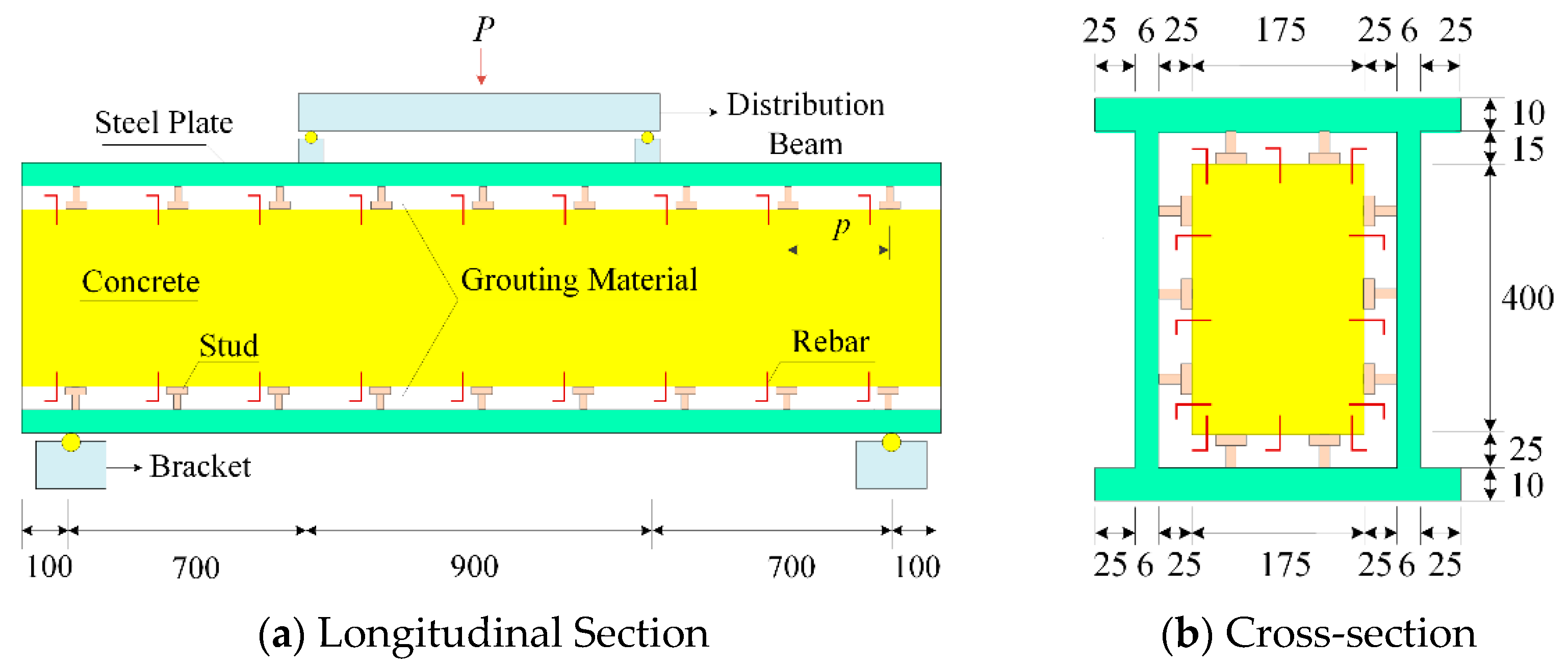
Table 2 summarizes the parameters of the specimens. To account for the reduction in concrete strength after 10 years of service, C25 concrete was used to represent the in situ concrete, which was originally graded as 350 in engineering practice. The elastic modulus of the grout was determined through compressive tests on a 150 mm × 150 mm × 150 mm grout cube after 28 days of curing [17]. Figure 11 shows the specimen dimensions. In Table 2, the subscripts “c” and “g” denote concrete and grouting material, respectively.
Table 2.
Parameters of Reinforcement Beam.
Figure 11.
Dimension of Reinforcement Beam.
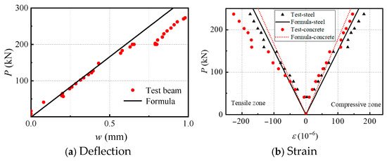
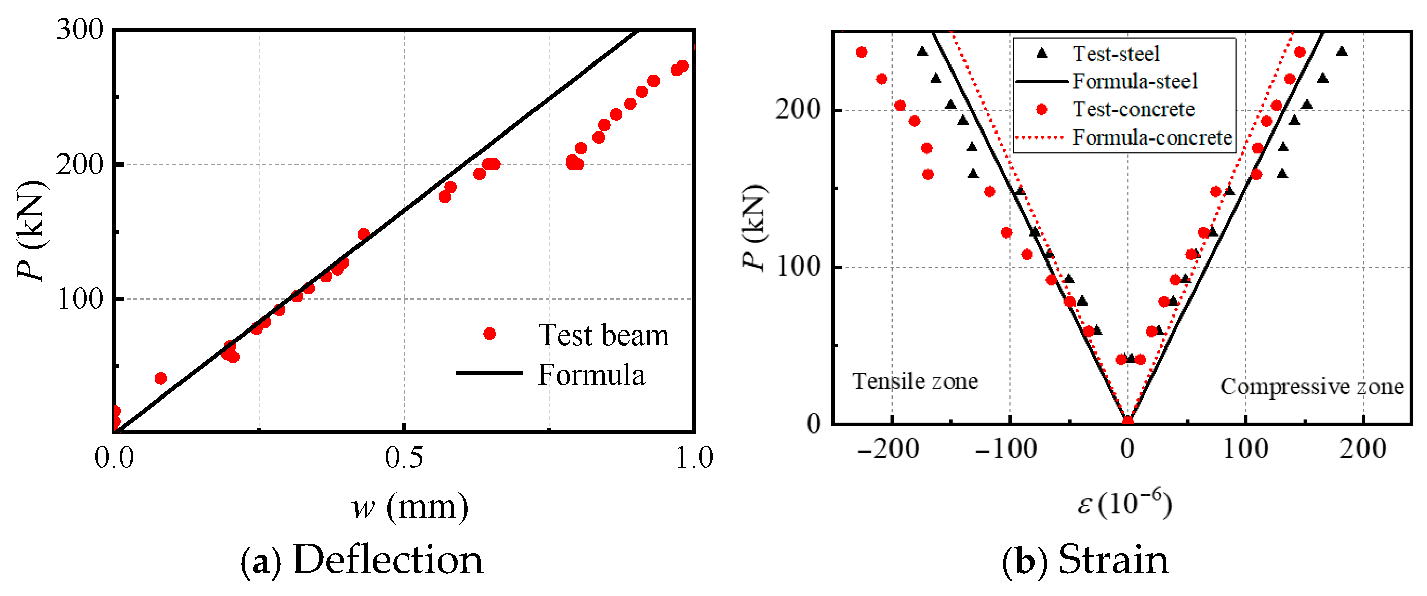
Based on mid-span deflection and material strain results from two-point bending tests on reinforced beams, a comparative validation was performed between theoretical formulas and experimental data. As the mechanical properties of the six experimental beams reported in the literature were closely matched, this study conducted the comparison using only the experimental data from beam L5. Deflections calculated using Equation (16) and strains calculated using Equation (17) for a simply supported beam were compared with measured mid-span values for deflection and for the strain of the steel plate and concrete at the top and bottom surfaces (Figure 12). The results indicate that the initial flexural stiffness of the experimental beams aligns well with theoretical predictions. When deflection exceeds 0.6 mm, a slight reduction in stiffness is observed. The strain values for the steel plate and concrete also generally agree with theoretical values, although some deviation occurs in the concrete tension zone; however, these deviations remain within acceptable engineering tolerances. Analysis of stiffness and strain variations suggests that these deviations are primarily due to damage in the concrete tension zone. Therefore, future work should incorporate numerical analysis to account for damage in both the concrete and grout. This nonlinear approach would allow for more accurate predictions of the flexural stiffness and ultimate load-bearing capacity of reinforced beams.
Figure 12.
Comparing Formula with Experiment for Deflection and Strain.
4. Stiffness Reduction Parameter Analysis
The slip between the bonding surface of the steel plate and grouting material can significantly affect the flexural stiffness of a reinforced beam. Therefore, the effects of the parameters that significantly influence the slip on the flexural stiffness of a reinforced beam must be assessed to design a more reasonable reinforcement scheme. The flexural stiffness of a reinforced beam can be calculated by multiplying the stiffness of a fully bonded beam by the stiffness reduction coefficient. According to the literature [21], the flexural stiffness reduction coefficient (η) can be expressed as follows:
where x0 denotes the position of maximum deflection.
By substituting the deflection into Equations (16) and (18) and introducing the equivalent length parameter (μ) into Equation (20), we obtain an analytical solution that considers the boundary conditions for both the two-point and even loads.
where subscripts t and e represent two-point and even loads, respectively. As suggested in previous studies [21], the effect of boundary conditions can be characterized by the equivalent length parameter (μl), which takes on different values depending on the type of support: (1) when simply supported at both ends, then μ = 1; (2) when clamped at both ends, then μ = 0.5; (3) when simply supported at one end and clamped at the other, then μ ≈ 0.7; (4) when clamped at one end and free at the other, then μ = 2.
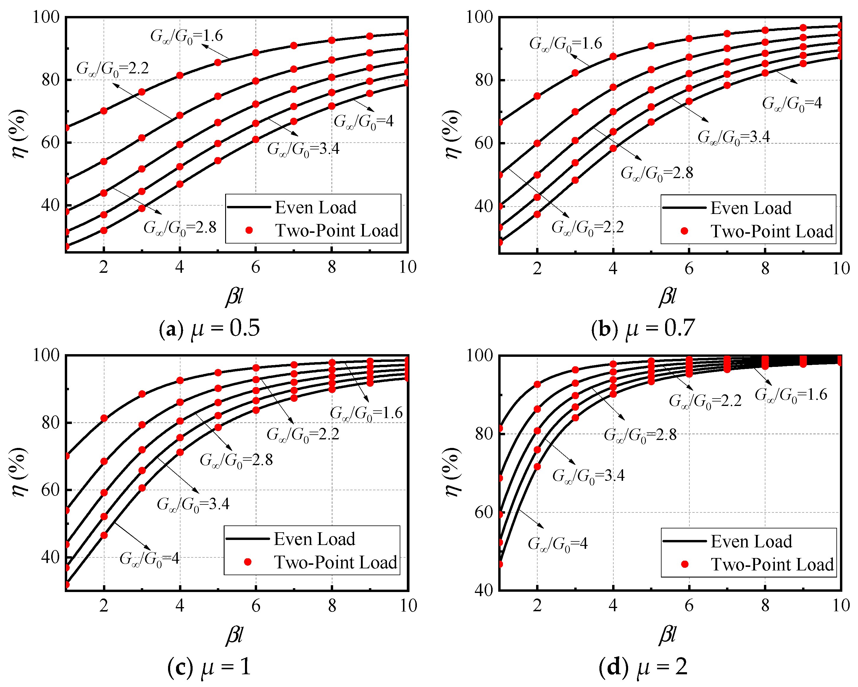
Equations (21) and (22) demonstrate that the flexural stiffness reduction coefficient (η) is primarily affected by three non-dimensional parameters: the boundary condition parameter (μ), composite action parameter (βl), and relative bending stiffness parameter (G∞/G0). The shear connection stiffness of a reinforced beam is denoted by βl, and the practical range for the partial composite action parameter is 0.1 < βl < 100 or often even narrower (1 ≤ βl ≤ 10) for many applications. Meanwhile, G∞/G0 represents the ratio of the flexural stiffness of complete bonding beams to the flexural stiffness of unbonded beams, and the practical range is 1 ≤ G∞/G0 ≤ 4 [24].
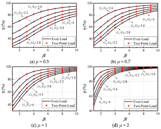
Figure 13 displays the influence of βl and G∞/G0 on η under two-point or even loads with varying boundary conditions. These findings indicate that the loading mode does not affect the bonding strength of the steel plate and grouting material. As βl approaches 100 and G∞/G0 approaches 1, η increases by 100%. In addition, η increases as μ increases.
Figure 13.
Variation in η with βl and G∞/G0 under Different Boundary Conditions.
In conclusion, Equation (22) can be employed as a general formula for the flexural stiffness reduction coefficient, accounting for boundary conditions. The coefficient is primarily influenced by the composite behavior parameter (βl), which reflects the degree of interface bonding, and the relative flexural stiffness parameter (G∞/G0), which indicates the extent of steel plate reinforcement. The results demonstrate that it is difficult to maintain the flexural stiffness of a reinforced beam without reduction. Even with strong interface bonding, significant stiffness reduction may still occur due to slippage when the steel plate reinforcement is considerable. Moreover, the ratio G∞/G0 is strongly correlated with the distance d between the centers of mass. As d approaches 0, G∞/G0 approaches 1, rendering stiffness loss negligible. Therefore, in engineering designs subjected to substantial uplift loads, adopting a symmetrical upper–lower reinforcement configuration can minimize stiffness degradation caused by slip. If a substantial increase in load-bearing capacity is desired, four-sided reinforcement is the optimal choice compared to other methods, as it allows for easier control of d to a smaller value. From a design perspective, conservative calculations indicate that satisfying the conditions βl ≥ 8 and G∞/G0 ≤1.6 can ensure that the reduction in flexural stiffness of the reinforced beam remains above 90%, providing a valuable reference for engineering applications. In addition, advanced fiber-reinforced grouts or functionally graded grout layers, which offer superior interface performance, merit further investigation in future studies.
5. Conclusions
This paper presents a flexural deformation calculation theory that accounts for the effect of slip in general reinforced cross-sections with bilateral symmetry. Based on this theory, analytical formulas for the deflection and strain of simply supported reinforced beams subjected to two-point or uniformly distributed loads are derived. In addition, a corresponding numerical method consistent with the proposed theory has been developed and validated. This numerical method offers a convenient and effective approach for designing beams reinforced with steel-plate–concrete composites. The conclusions drawn from this study are as follows:
- (1)
- The flexural stiffness of reinforced beams is influenced by the boundary condition parameter (μ), the composite action parameter (βl), and the relative bending stiffness parameter (G∞/G0), but not to the loading mode. As βl approaches 10 and G∞/G0 approaches 1, η approaches 100%. In cases where high stiffness is required, reducing interfacial slip can minimize the loss of flexural stiffness in composite structures. Conservative calculations indicate that satisfying the conditions βl ≥ 8 and G∞/G0 ≤ 1.6 during design can ensure that the reduction in flexural stiffness of the reinforced beam remains above 90%. This provides a valuable reference for engineering design.
- (2)
- In the design of steel–concrete composite reinforcement systems, priority should be given to optimizing the cross-sectional geometry of the reinforcing steel plate to minimize the distance between the neutral axes and thereby reduce stiffness loss. Subsequently, attention should be directed toward the bonding performance at the interface, with appropriate selection of the strength and spacing of shear studs to limit interfacial slip. In addition, increasing the strength of the grouting material may further enhance interface performance, and continued advancements in this area are highly anticipated.
Author Contributions
Conceptualization, K.Y. and P.Z.; methodology, K.Y. and X.X.; software, K.Y.; validation, K.Y.; formal analysis, K.Y.; investigation, K.Y., A.Z. and P.Z.; resources, X.X. and A.Z.; data curation, K.Y.; writing—original draft preparation, K.Y.; writing—review and editing, K.Y.; visualization, K.Y.; supervision, X.X.; project administration, A.Z. and X.X.; funding acquisition, X.X. All authors have read and agreed to the published version of the manuscript.
Funding
The APC was funded by Zhejiang Provincial Construction and Scientific Research Projects (No. 2019K181).
Data Availability Statement
The original contributions presented in this study are included in the article. Further inquiries can be directed to the corresponding author.
Acknowledgments
I am deeply grateful to my family and friends who have always supported me behind the scenes. Thank you all.
Conflicts of Interest
Author Peiyun Zhu was employed by the company Yalong River Hydropower Development Company, Ltd. The remaining authors declare that the research was conducted in the absence of any commercial or financial relationships that could be construed as a potential conflict of interest.
References
- Zhou, J.; Wang, L. Repair of fire-damaged reinforced concrete members with axial load: A review. Sustainability 2019, 11, 963. [Google Scholar] [CrossRef] [Scilit]
- Günaslan, S.E.; Karaşin, A.; Öncü, M.E. Properties of FRP materials for strengthening. Int. J. Innov. Sci. Eng. Technol. 2014, 1, 656–660. [Google Scholar]
- Gudonis, E.; Timinskas, E.; Gribniak, V.; Kaklauskas, G.; Arnautov, A.K.; Tamulėnas, V. FRP reinforcement for concrete structures: State-of-the-art review of application and design. Eng. Struct. Technol. 2013, 5, 147–158. [Google Scholar] [CrossRef] [Scilit]
- Banu, D.; Taranu, N. Traditional solutions for strengthening reinforced concrete slabs. Bul. Institutului Politeh. Din Lasi. Sect. Constr. Arhit. 2010, 56, 53. [Google Scholar]
- Fakharifar, M.; Chen, G.; Wu, C.; Shamsabadi, A.; Elgawady, M.A.; Dalvand, A. Rapid repair of earthquake-damaged RC columns with prestressed steel jackets. J. Bridge Eng. 2016, 21, 04015075. [Google Scholar] [CrossRef] [Scilit]
- Huang, Z.; Liew, J.R. Nonlinear finite element modelling and parametric study of curved steel–concrete–steel double skin composite panels infilled with ultra-lightweight cement composite. Constr. Build. Mater. 2015, 95, 922–938. [Google Scholar] [CrossRef] [Scilit]
- Lin, Y.; Yan, J.; Wang, Y.; Fan, F.; Zou, C. Shear failure mechanisms of SCS sandwich beams considering bond-slip between steel plates and concrete. Eng. Struct. 2019, 181, 458–475. [Google Scholar] [CrossRef] [Scilit]
- Chen, H.; Lai, H.; Qiu, Y.; Chen, R. Reinforcing distressed lining structure of highway tunnel with bonded steel plates: Case study. J. Perform. Constr. Facil. 2020, 34, 04019082. [Google Scholar] [CrossRef] [Scilit]
- Song, P.S.; Hwang, S. Mechanical properties of high-strength steel fiber-reinforced concrete. Constr. Build. Mater. 2004, 18, 669–673. [Google Scholar] [CrossRef] [Scilit]
- Kang, J.T.; Wang, X.F.; Yang, J.; Du, Y.G. Strengthening double curved arch bridges by using extrados section augmentation method. Constr. Build. Mater. 2013, 41, 165–174. [Google Scholar] [CrossRef] [Scilit]
- Yang, J.; Chen, R.; Zhang, Z.; Zou, Y.; Zhou, J.; Xia, J. Experimental study on the ultimate bearing capacity of damaged RC arches strengthened with ultra-high performance concrete. Eng. Struct. 2023, 279, 115611. [Google Scholar] [CrossRef] [Scilit]
- Zhuang, L.D.; Zhao, J.Z.; Wang, C.; Liang, H.Q.; Tang, M.X. Experimental study on the composite reinforcement method for single-column piers in existing bridges. In Structures; Elsevier: Amsterdam, The Netherlands, 2024; Volume 65, p. 106734. [Google Scholar]
- Xie, X.L.; Gou, W.X.; Pang, M.L.; Qiu, C. Dynamic Characteristics of RC Rigid Frame Arch Bridge Strengthened by Plate-Truss Combination. J. South China Univ. Technol. (Nat. Sci. Ed.) 2023, 31–43. [Google Scholar]
- Wang, C.S.; Yuan, Z.Y.; Guo, X.Y.; Gao, S.; Ren, T.X. Flexural behavior experiment of reinforced concrete T-beams with steel plate-concrete composite strengthening. J. Traffic Transp. Eng. 2010, 32–40. (In Chinese) [Google Scholar]
- Shi, X.W.; Yuan, Z.Y.; Ma, Y.Q.; Feng, W.; Chen, L. Prestressed concrete box girders strengthened with composition of steel plate and concrete. J. Chang. Univ. (Nat. Sci. Ed.) 2012, 32, 58–62+90. (In Chinese) [Google Scholar]
- Taniguchi Saito, M.; Suzhi, K. The existing RC of the active composite structure Study on Retrograde Technology of viaduct. In Proceedings of the 10th Symposium on the Active Use of Combinatorial and Synthetic Structures, Xi’an, China, 23–25 May 2014. (In Japanese) [Google Scholar]
- Lin, J.H.; Zhang, A.J.; Zhu, D.; Yang, K.H.; Shen, X.T.; Xie, X. Experimental Study on the Load-Bearing Capacity of Steel-Concrete Composite Strengthening Beam. J. Civ. Environ. Eng. 2023, 45, 141–149. (In Chinese) [Google Scholar]
- Girhammar, U.A.; Gopu, V.K.A. Composite Beam-Columns with Interlayer Slip-Exact Analysis. J. Struct. Eng. 1993, 119, 1265–1282. [Google Scholar] [CrossRef] [Scilit]
- Girhammar, U.A.; Pan, D.H. Exact Static Analysis of Partially Interaction Composite Beams and Beam-Columns. Int. J. Mech. Sci. 2007, 49, 239–255. [Google Scholar] [CrossRef] [Scilit]
- Nie, J.G.; Shen, J.M.; Yuan, Y.S. A general formula for calculating the deformation of simply supported steel-concrete composite beams. Eng. Mech. 1994, 11, 21–27. (In Chinese) [Google Scholar]
- Nie, J.G.; Shen, J.M.; Yu, Z.W. A Reduced Stiffness Method for Calculating Deformation of Steel-Concrete Composite Beams with the Consideration of Slip Effect. China Civ. Eng. J. 1995, 28, 11–17. (In Chinese) [Google Scholar]
- Al-musawi, H.; Figueiredo, F.P.; Guadagnini, M.; Pilakoutas, K. Shrinkage properties of plain and recycled steel–fibre-reinforced rapid hardening mortars for repairs. Constr. Build. Mater. 2019, 197, 369–384. [Google Scholar] [CrossRef] [Scilit]
- Daneshvar, D.; Deix, K.; Robisson, A.; Shafei, B. Investigation of drying shrinkage effects on sloped concrete-concrete composites. In Computational Modelling of Concrete and Concrete Structures; CRC Press: Boca Raton, FL, USA, 2022; pp. 634–639. [Google Scholar]
- Girhammar, U.A. A simplified analysis method for composite beams with interlayer slip. Int. J. Mech. Sci. 2009, 51, 515–530. [Google Scholar] [CrossRef] [Scilit]

Disclaimer/Publisher’s Note: The statements, opinions and data contained in all publications are solely those of the individual author(s) and contributor(s) and not of MDPI and/or the editor(s). MDPI and/or the editor(s) disclaim responsibility for any injury to people or property resulting from any ideas, methods, instructions or products referred to in the content. |
© 2026 by the authors. Licensee MDPI, Basel, Switzerland. This article is an open access article distributed under the terms and conditions of the Creative Commons Attribution (CC BY) license.