


Abstract
This paper proposes a repair-oriented steel tie beam joint with shape memory alloy (SMA) butterfly springs for double-column piers. In the proposed detail, the conventional welded connection is replaced by a bolted fuse region to redirect inelastic demand toward replaceable components. Joint component-level finite element simulations under cyclic loading were conducted to evaluate stress redistribution, cumulative plastic strain, hysteretic response, stiffness variation, cumulative energy dissipation, and residual deformation. The results indicate a repairability-oriented response characterized by damage localization and residual deformation control, rather than a strength-dominated enhancement. Compared with the non-SMA bolted reference joint, the SMA joints show a modest reduction in the peak stress of key plates, reduce the relative peak PEEQ indicator by within the adopted no-fracture finite element framework, and lower the residual deformation index by about . The dual-row SMA arrangement provides better load sharing and slightly higher energy dissipation than the single-row arrangement. Although the SMA joints dissipate less cumulative energy than the non-SMA reference joint, the results suggest that the proposed detail may provide a repair-oriented connection concept when post-earthquake damage localization, replaceability, and residual deformation control are prioritized.
1. Introduction
Double-column pier bents are widely used in viaducts and overpasses because of their clear load paths and suitability for rapid construction. Post-earthquake reconnaissance shows that their seismic vulnerability is often governed by the inter-column tie beam joint and its force transfer mechanism. Under strong shaking, damage may concentrate in the joint region, the column plastic hinge regions, or the tie beam connection, thereby compromising bent integrity. Repairability is also critical because damage in concealed connection regions can prolong traffic closure and delay functional recovery. These observations motivate a repair-oriented joint strategy that steers inelastic demand toward replaceable components while providing self-centering capacity to reduce residual deformation.
Stress concentration in conventional joint regions may cause local concrete crushing, bar buckling, reduced ductility, and unstable hysteretic behavior, as reported by McCormick et al. [1]. Xie et al. [2] showed that rigid pier–tie beam connections may exhibit poor deformation compatibility and brittle shear-dominated failure under increasing cyclic demand. When seismic resistance relies on column plastic hinging, irreversible deformation may lead to large residual displacement and weak post-earthquake recoverability [3,4]. Therefore, repair-oriented joint details are needed to improve both seismic resilience and post-earthquake recoverability. Existing experimental studies provide useful benchmarks for repair-oriented seismic devices. Oyguc et al. [5] combined component-level cyclic tests and shake table tests to evaluate tube-in-tube buckling-restrained braces for retrofitting substandard RC frames, demonstrating the role of experimental evidence in confirming deformation capacity, energy dissipation, and seismic resilience.
Shape memory alloys (SMAs) are promising for seismic resilience because superelastic NiTi provides restoring capability and stable hysteretic behavior [6,7]. Although SMA devices may increase initial cost, they can reduce post-earthquake repair demand and downtime through self-centering and damage localization [8]. DesRoches and Smith [9] and DesRoches et al. [10] confirmed the seismic potential and stable cyclic superelasticity of SMA components. In bridge engineering, SMA devices have been explored in bearings, dampers, reinforcement detailing, and superelastic SMA bars for precast segmental bridge piers [11]. However, systematic research on the use of SMA-based devices in tie beam joints between double-column piers remains limited, particularly from the perspective of repair-oriented design. To address this gap, the present study introduces SMA butterfly springs into the tie beam joint and combines their self-centering and energy-dissipation mechanisms with a plastic hinge relocation strategy to improve post-earthquake recoverability. Accordingly, this paper develops three bolted tie beam joint configurations and evaluates their cyclic seismic behavior through finite element analysis.
The use of SMA devices in seismic applications relies first on the stable and recoverable cyclic response of the material itself. DesRoches et al. [10] confirmed that superelastic SMA bars can sustain repeated cyclic loading with stable recoverable deformation. For numerical simulation, such recoverable nonlinear behavior requires an appropriate constitutive representation. Liew et al. [12] developed a multidimensional SMA constitutive framework suitable for finite element implementation. At the structural level, Zhan et al. [7] further showed that SMA hysteresis can be incorporated into response control models for vibration mitigation applications.
Based on these material and modeling foundations, SMA components have been incorporated into various structural systems to improve self-centering capacity and post-earthquake recoverability. Sultana and Youssef [13] reported that SMA moment frames can reduce residual drift and peak deformation. Dolce et al. [14] and Ocel et al. [15] showed that SMA-based devices and steel connections can improve cyclic recovery and reduce residual deformation. Speicher et al. [16] and Abolmaali et al. [17] further demonstrated the feasibility of SMA-based self-centering connections and fasteners. These studies indicate that SMAs can function not only as a restoring material but also as a replaceable connection component in bolted seismic details. Ma et al. [18] and Yam et al. [19] examined the use of SMA bolts in end-plate connections to enhance self-centering performance. More recently, Dou et al. [20] experimentally investigated full-scale disc spring self-centering steel beam–column joints under cyclic loading and reported flag-shaped hysteresis, damage control, and effective residual drift reduction, providing useful evidence for spring-based self-centering connection concepts. In bridge engineering, this self-centering concept has also been extended from building connections to bridge substructures. Akbarnezhad et al. [21] proposed SMA-restrained rocking bridge columns that combine self-centering with supplemental energy dissipation.
Taken together, these studies suggest that SMA-enabled resilience should be evaluated not only by strength and energy dissipation but also by repairability and residual deformation control. Katsimpini et al. [22] and Chen et al. [23] highlighted the need for device-based damage control and repairable pier details in seismic-resistant structural systems. Rahman and Billah [24] further showed that SMA reinforcement can improve the post-earthquake functionality of bridge bents. Nevertheless, most existing studies have focused on SMA materials, beam–column connections, rocking columns, or supplemental dampers. SMA-based repair-oriented details for the sleeve–plate welded transition in double-column pier tie beam joints remain insufficiently investigated. To fill this gap, this study proposes a modular bolted fuse segment incorporating SMA butterfly spring stacks and evaluates its cyclic performance through finite element simulations. Three joint configurations, namely, J-DS, J-IS, and J-OB, are compared to examine how SMA layout influences stress redistribution, plastic strain localization, energy dissipation, and residual deformation. Therefore, this study emphasizes the relative effects of SMA layout on repairability-oriented seismic behavior, including damage localization, self-centering tendency, and residual deformation control, rather than maximizing strength or cumulative energy dissipation alone.
2. Design of Joint Configuration
2.1. Engineering Background
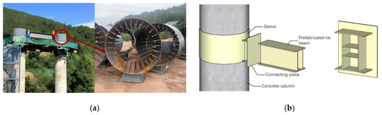
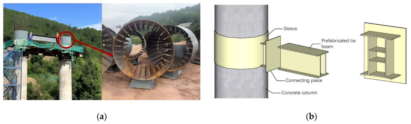
Figure 1 shows the engineering prototype and original sleeve-connected pier–tie beam detail. The bridge shown in Figure 1 was adopted as the prototype because it represents a common industrialized expressway bent: a circular double-column pier system with a pier diameter and a mid-height tie beam. The pier–tie beam joint uses a steel sleeve socket connection, with stiffening ribs guiding force transfer across the sleeve-to-beam transition. The joint is a rigid welded assembly following the sequence “sleeve–connecting plate–tie beam,” and a triangular steel corbel is arranged to facilitate prefabricated erection.
Figure 1.
Engineering prototype and original sleeve-connected joint detail: (a) bridge prototype; (b) schematic of the sleeve-connected pier–tie beam joint.
From a seismic perspective, this prefabricated detail may lead to an unfavorable damage mechanism. Although most welds may remain intact, the grouting sleeve–connecting plate interface can become the governing weak link. Under cyclic loading, inelastic action may localize at the sleeve–plate welded interface and accelerate yielding in the sleeve region. This localization is detrimental because it couples joint degradation with increased demand transfer to the pier columns, thereby raising the likelihood of column damage. Because this damage occurs within the load transfer joint, repair may require cutting, re-welding, or local reconstruction in confined space.
To address this weakness, an optimized sleeve-connected steel tie beam joint is proposed, as shown in Figure 1b. The objective is to relocate the plastic hinge away from the sleeve–plate welded region and redirect demand toward replaceable components. The proposed scheme transforms a concealed weld-dominated damage mode into a more visible and replaceable device-dominated mechanism. SMA butterfly springs are introduced to provide self-centering and energy dissipation while maintaining constructability.
2.2. Design of the Tie Beam Joint in Double-Column Piers
Plastic hinge relocation aims to steer inelastic demand away from hard-to-repair regions and toward a replaceable fuse zone. Oyguc and Bozan [25] showed that replaceable fuse detailing can localize inelastic deformation and improve post-earthquake repairability. Accordingly, a predefined fuse section is introduced at the tie beam–connector interface to promote plastic demand concentration in the replaceable fuse segment rather than at the sleeve–plate transition.
The joint was arranged following a capacity design concept to guide the intended damage control mechanism. The predefined fuse region was placed at the tie beam–connector interface, while the surrounding plates, welds, sleeve-anchored region, and adjacent tie beam segment were treated as protected load transfer components, consistent with bridge capacity design practice [26]. In the present joint component study, this concept is examined through the stress and plastic strain responses of the fuse region, bolts, plates, SMA components, and adjacent load transfer regions.
An SMA butterfly spring device is then incorporated into the fuse segment to provide coordinated energy dissipation and self-centering. Chen et al. [27] showed that SMA-based self-centering bridge systems can reduce residual deformation and improve resilience. Qian et al. [28] also verified that SMA-enabled bridge components can control residual deformation while maintaining stable cyclic performance.
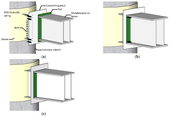
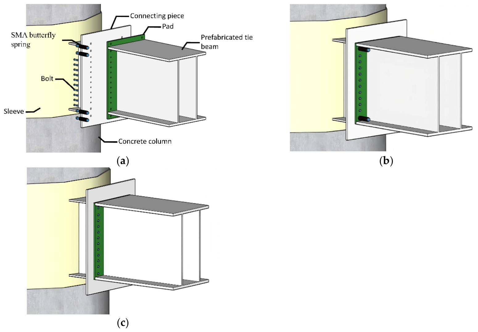
To facilitate comparison, the three joint configurations were kept consistent in the basic tie beam geometry, plate thickness, material properties, boundary conditions, loading protocol, and intermediate bolt hole layout. The planned geometric differences were concentrated in the SMA installation region, including the number and position of SMA butterfly spring rows, the SMA-connected holes, and the local plate height required for device installation. For brevity, only representative three-dimensional views of the three joint configurations are retained in the main text (Figure 2). The principal dimensions that define the bolt layout, pad plate geometry, and SMA installation are given directly in the following subsections.
Figure 2.
Representative three-dimensional views of the three joint configurations: (a) J-DS; (b) J-IS; (c) J-OB.
Three joint designs were developed to quantify how SMA amount and placement affect the force–deformation mechanism and damage location. J-DS (Dual-System SMA Joint) adopts a dual-row SMA layout at both the upper and lower flange bolt lines. Two parallel SMA butterfly spring rows are installed at each flange level to provide symmetric resistance, reduce prying-induced eccentricity, and supply restoring force and energy dissipation. J-IS (Internal-SMA Joint) represents a material-efficient configuration with a single SMA butterfly spring row installed at the inner side of the upper and lower flange bolt lines. This layout is used to assess whether a reduced SMA quantity can still provide adequate self-centering and energy dissipation. J-OB (ordinary bolted reference joint) retains the basic tie beam section and does not include SMA butterfly spring devices, serving as the non-SMA bolted baseline for evaluating the influence of SMA-enabled detailing on hysteresis response, stiffness variation, damage localization, and residual deformation.
The SMA butterfly spring stack is detailed as a bolt-on subassembly without additional field welding. At the component level, post-earthquake inspection is directed to the accessible fuse region, including spring stack damage, long-bolt yielding or permanent deformation, visible slip marks, bolt hole elongation, retained-plate deformation, or loss of bolt tightness in the device region. Component replacement is expected to be feasible when the retained plates remain serviceable, and bolt removal or reinstallation is not obstructed by hole deformation. The expected repair sequence is to inspect the fuse region, remove damaged long bolts or spring stacks, install new components, and retighten the bolts, consistent with the replaceable hinge repair concept proposed by Oyguc and Bozan [25]. Routine maintenance may focus on bolt pretension verification [29].
2.2.1. Dual-Row SMA Joint Design
J-DS adopts SMA butterfly spring assemblies on both sides of the upper and lower flange bolt lines. The tie beam pad plate is with predrilled bolt holes. The two uppermost and two lowermost bolt holes are assigned to long bolts connected to the SMA butterfly springs, and the hole diameter is . The ten intermediate bolt holes have a diameter of and a spacing of . The plate thickness is .
The SMA butterfly spring assembly was developed with reference to the SMA washer-based self-centering concept reported by Chen et al. [27], in which SMA washer components were used to provide restoring force and residual deformation control in bridge systems. Each SMA butterfly spring has dimensions of , and the spring washer size is . The butterfly springs are stacked in 18 paired groups. The total length of the spring stack is .
The main connecting component is an perforated steel plate. Four transverse and two longitudinal steel plates are welded to the rear part of the main steel plate. The rear welded plate connects to the sleeve and matches its curvature. The assembled J-DS configuration is shown in Figure 2a. The matching bolt hole pattern allows the SMA-connected long bolts to form the main restoring force path, while the intermediate bolts provide force transfer and interface restraint. The plate width and connecting plate height provide edge distance and lever arm for the dual-row SMA layout.
Therefore, J-DS represents the most device-intensive configuration, intended to enhance load sharing and restoring force participation under cyclic opening and closing of the joint interface.
2.2.2. Single-Row SMA Joint Design
J-IS uses one inner SMA row at the upper and lower flange bolt lines. The spring dimensions are unchanged, while the pad plate height is reduced to match the tie beam depth.
The tie beam pad plate is with reserved bolt holes. The upper and lower edge bolt holes are assigned to long bolts connected to the SMA butterfly springs, with a hole diameter of , consistent with the J-DS detail. The ten intermediate bolt holes are in diameter, and the plate thickness is .
Compared with J-DS, J-IS reduces the pad plate height from to and retains only one internal SMA row at each flange level. The connecting plate removes the outer long-bolt rows while preserving the same transverse alignment, intermediate bolts, and thickness. The assembly procedure for J-IS is similar to that of J-DS, and the assembled J-IS configuration is shown in Figure 2b. Thus, J-IS is a reduced-device alternative to J-DS.
2.2.3. Design of the Non-SMA Bolted Reference Joint
J-OB was used as the non-SMA reference configuration for comparison with the SMA-enabled joints. In this model, the SMA butterfly spring subassembly was removed, and conventional bolts were retained at the corresponding locations, providing a bolted baseline for evaluating the SMA-enabled detailing.
The tie beam pad plate is with reserved bolt holes. Compared with J-DS, the long bolts used to clamp the SMA butterfly springs at the upper and lower bolt lines are replaced by standard bolts in J-OB, and the corresponding hole diameter is . The middle bolts and plate thickness are consistent with those of J-DS. The bolt-hole arrangement of the connecting plate is modified in the same manner as that of the tie beam pad plate. The assembled J-OB configuration is shown in Figure 2c. Thus, J-OB has the same pad plate size and thickness as J-IS, but the edge holes are changed from SMA-connected holes to conventional bolt holes. This treatment eliminates the SMA subassembly while preserving the basic plate layout and load transfer path, allowing direct comparison with the SMA-enabled configurations. Therefore, J-OB serves as the non-SMA reference model for evaluating the relative contribution of the SMA butterfly spring devices to damage redistribution, cyclic response, and residual deformation control. The original welded sleeve–plate detail is used as the engineering prototype in Section 2.1, whereas J-OB provides a non-SMA bolted baseline for isolating the device effect.
3. Finite Element Numerical Simulation of Joints
3.1. SMA Superelastic Constitutive Model
The superelastic response of the NiTi-based SMA was modeled using an Auricchio-type constitutive formulation suitable for nonlinear cyclic loading. This formulation captures stress-induced phase transformation and martensite reorientation, enabling simulation of the flag-shaped hysteresis of superelastic SMA components.
Following Auricchio et al. [30], three mechanisms are considered: austenite-to-martensite transformation (), reverse transformation (), and martensite reorientation (). The material is assumed isotropic, with stress () and temperature () as state variables. The phase fractions of austenite () and martensite () are updated through the following evolution relations.
For reproducibility, the independent SMA material inputs used in the finite element model were defined as , , , , and . These parameters were assigned to the built-in SuperElasticity material model to represent the recoverable phase transformation response of NiTi-based shape memory alloy components under cyclic loading. Fatigue damage and fracture of the SMA material were not considered in the present study. Under the isothermal superelastic assumption, , , , and were not specified as independent inputs; thermal effects were represented by and the associated temperature-dependent coefficients. The parameter set reported above corresponds to the independent SMA material inputs used in the finite element model, while the remaining symbols in Equations (1)–(13) are used to describe the Auricchio-type transformation framework.
During martensite reorientation (), the martensite fraction remains constant. During forward () and reverse () transformations, the phase fractions evolve.
where and denote the austenite-to-martensite and martensite-to-austenite transformations, respectively.
- (1)
- For the forward transformation from austenite to martensite ()
The Drucker–Prager loading function is introduced as follows:
where represents the stress deviation and . is the trace of the matrix. is the second-order identity tensor. Both and are material parameters. represents pressure. is the Euclidean norm.
The onset and completion of the phase transformation are defined by the following loading functions:
with
where , , , and are all material parameters.
The transition conditions are:
The evolution of the single-variant martensite fraction can be described using an exponential form:
Alternatively, the following linear form can be used:
where is a material parameter that represents the phase transformation rate.
The scalar parameter is defined as:
For the reverse transformation from martensite to austenite (), the and terms are interchanged.
- (2)
- Martensite variant reorientation ()
The Drucker–Prager loading function is defined as:
with
where , , and are material parameters.
The transition conditions are:
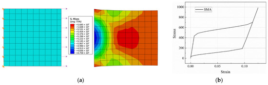
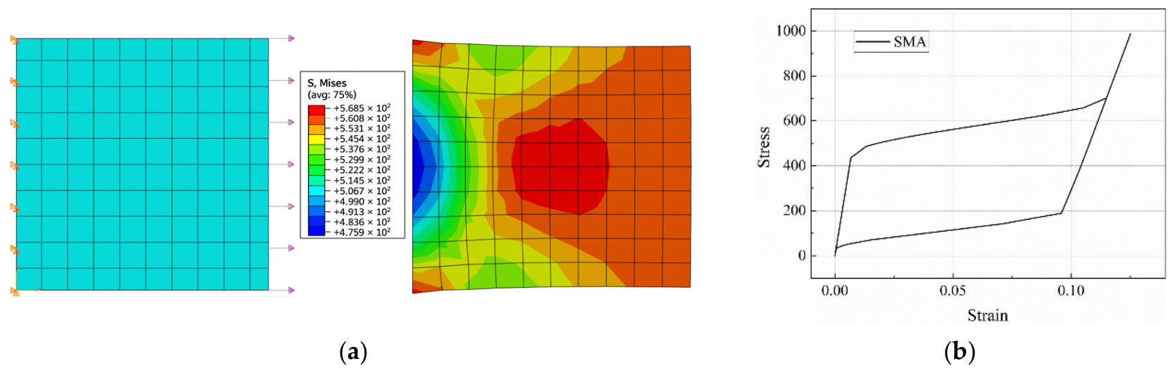
To check the implementation of the SMA material model, a simple material-level numerical simulation was conducted before the joint-level analysis, as shown in Figure 3. A two-dimensional SMA specimen was established, and cyclic displacement-controlled loading was applied. The extracted stress–strain response exhibited the typical features of SMA superelasticity, including an initial elastic branch, a stress-induced transformation stage, unloading recovery, and limited residual strain. This response is qualitatively consistent with the typical recoverable cyclic behavior reported in experimental studies on superelastic SMA wires and bars [10]. Therefore, this material-level check was used to confirm the numerical implementation of the SuperElasticity model, rather than to provide a direct experimental calibration of the SMA material parameters.
Figure 3.
Material-level numerical check of the SMA SuperElasticity model: (a) finite element specimen and von Mises stress distribution; (b) simulated stress–strain response under cyclic loading.
3.2. Finite Element Model
The finite element models were established in Abaqus/Standard and analyzed using a nonlinear quasi-static procedure. The steel plates, tie beam, bolts, and SMA butterfly spring components were discretized using C3D8R eight-node linear brick elements with reduced integration. Recent finite element studies on hybrid and high-strength steel structures have emphasized that cyclic or seismic numerical analyses should clearly report material definitions, element types, component interactions, contact treatments, and loading protocols [31,32,33]. In addition, benchmark-oriented finite element studies on cyclic steel subassemblies have shown that a comparison with experimental observations, including failure modes and mechanical indexes, is important for improving the credibility of numerical interpretation [34]. Accordingly, the main steel material parameters used in the numerical models are summarized in Table 1.
Table 1.
Steel material parameters used in the finite element models.
The steel components and bolts were modeled using an isotropic elastoplastic material definition based on the parameters listed in Table 1.
3.2.1. Contact and Constraint Definitions
Interactions among the tie beam, pad plate, connecting plate, bolts, and SMA stacks were defined to capture bearing transfer, interface opening/closing, and local contact behavior.
Normal contact was defined as hard contact with separation allowed after contact, enabling interface opening and re-contact under cyclic loading [35]. In the tangential direction, a penalty-based contact formulation with a small stabilizing coefficient of 0.005 was adopted to improve the robustness of nonlinear contact iterations. This setting was introduced as a numerical regularization rather than as a calibrated representation of tangential resistance at bolted steel interfaces. Accordingly, this tangential setting was not used to quantify friction-controlled slip or bolt pretension-dependent interface behavior; it was applied consistently to the three joint configurations to support relative comparison under the same contact regularization. Therefore, the dominant local mechanisms considered in the present models are normal contact, bolt-bearing interaction, interface opening/closing, localized plasticity, and SMA butterfly spring engagement. The same interaction scheme was applied consistently to J-DS, J-IS, and J-OB, so that the relative differences in response could be attributed mainly to joint detailing and SMA layout. Interfaces expected to remain bonded were modeled using tie constraints.
3.2.2. Mesh Discretization
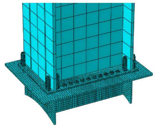
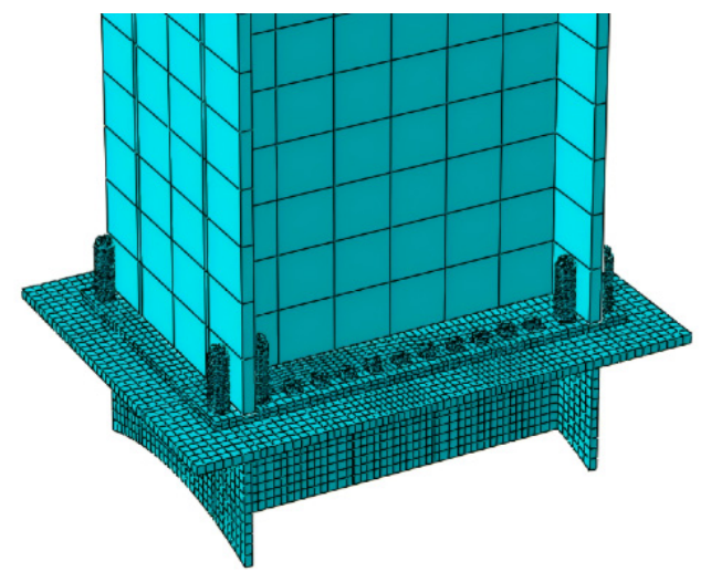
The connector assembly was partitioned into regular sub-regions for structured meshing. Local mesh refinement was applied around bolt holes to capture stress and strain gradients in the bearing and contact zones. The characteristic element size was set to near the bolt holes and for the overall joint unit. For the J-DS pad plate, two elements were used through the thickness to improve the representation of local bending and contact transfer.
For J-IS and J-OB, the pad plate geometry is simpler, and the through thickness meshing was kept consistent without additional layering. The characteristic element size was set to for the long rod bolts and for the short rod bolts to better resolve axial deformation and local interaction near the bolt–plate interfaces. For the SMA butterfly spring stack, a finer characteristic element size of was adopted to improve the representation of local deformation and stress transfer within the device, particularly near the washer contact and bending-sensitive regions. By contrast, the tie beam component is geometrically simpler and located away from the critical force transfer region; therefore, a coarser mesh with a characteristic element size of was adopted to improve computational efficiency. A representative mesh pattern of the J-DS model together with the local refinement around the bolt hole region is shown in Figure 4. J-IS and J-OB adopted the same meshing strategy, with only geometry-specific adjustments required by the reduced pad-plate configuration.
Figure 4.
Representative finite element mesh and local refinement strategy for the J-DS model.
A mesh sensitivity study was conducted for all three joint models (J-DS, J-IS, and J-OB) using coarse, baseline, and refined meshes. The baseline mesh was adopted because further refinement changed the peak force, hysteretic energy dissipation (loop area), and maximum plastic strain in the critical connection region by less than , indicating mesh convergence for the joint-level response measures considered in this study [36,37]. Accordingly, local stress differences with magnitudes close to this threshold were interpreted cautiously as modest numerical trends rather than as standalone evidence of substantial performance improvement. No ductile damage evolution, fracture criterion, or element deletion was introduced in the present models. Therefore, the local PEEQ values at bolt-bearing hot spots were used to identify plastic localization patterns within the no-fracture numerical framework, rather than to evaluate bolt fracture or post-fracture behavior.
3.2.3. Boundary Conditions
The lower surface of the connector assembly was fully constrained in translation and rotation along the , , and directions. The same boundary conditions were applied to J-DS, J-IS, and J-OB for consistency. This boundary condition represents a simplified joint component subassembly extracted from the sleeve-connected pier–tie beam region of the engineering prototype, rather than a full-pier boundary representation. Controlled boundary and loading conditions have also been used in connection subassembly studies to focus on local connection behavior under cyclic demand [38,39].
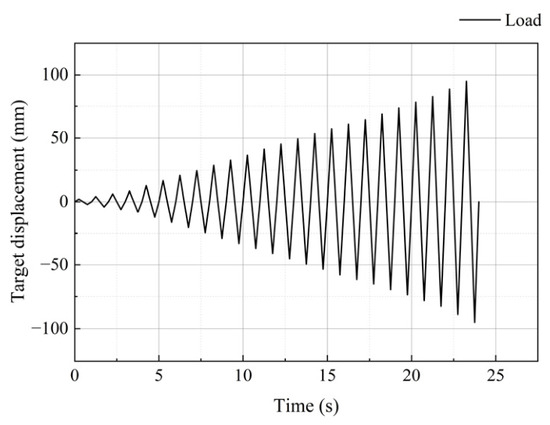
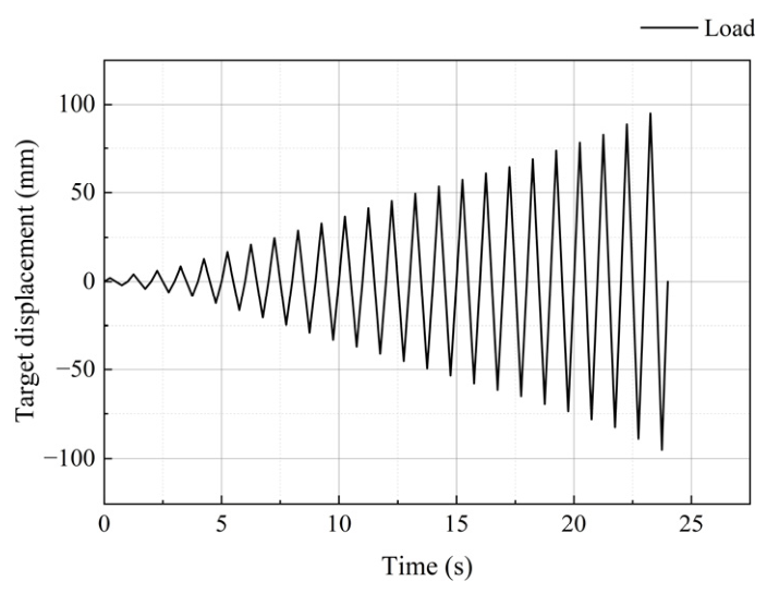
A displacement-controlled quasi-static loading protocol was applied at the tie beam loading section (Figure 5) to obtain the force–displacement hysteretic response [40]. The displacement amplitude increased in steps of , and each loading level was applied once within a normalized quasi-static analysis step. This simplified single-cycle displacement increment protocol was adopted to compare the first-cycle response of the three joint configurations under identical numerical loading conditions. Therefore, the obtained hysteretic response is used for relative comparison of force–deformation behavior, loop area, and residual deformation within the adopted finite element framework, rather than for evaluating repeated-cycle degradation or low-cycle fatigue at each displacement amplitude.
Figure 5.
Displacement-controlled loading protocol.
All joint configurations use identical material properties and loading/boundary conditions; therefore, the observed differences are interpreted as relative response differences associated with the SMA-enabled detailing under the adopted single-cycle protocol. Column flexibility, tie beam axial force, gravity effects, and system-level seismic demand were not explicitly included in this joint component model. Therefore, the absolute values of reaction force, secant stiffness, cumulative loop area, and residual deformation may differ from those of a full bridge pier system. The present results are, therefore, used for comparative evaluation of the three joint configurations under consistent boundary and loading conditions.
4. Results and Discussion of Joint Seismic Performance
Joint performance is evaluated using stress and strain fields, force–displacement hysteresis, backbone curves, displacement amplitude-dependent secant stiffness, cumulative loop area, and residual deformation. Together, these joint-level metrics are used to compare strength, deformation response, hysteretic energy, and residual deformation control across the three joint configurations under the adopted single-cycle numerical protocol.
4.1. Stress and Strain Analysis
4.1.1. Stress Distribution
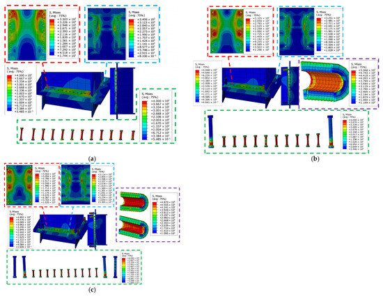
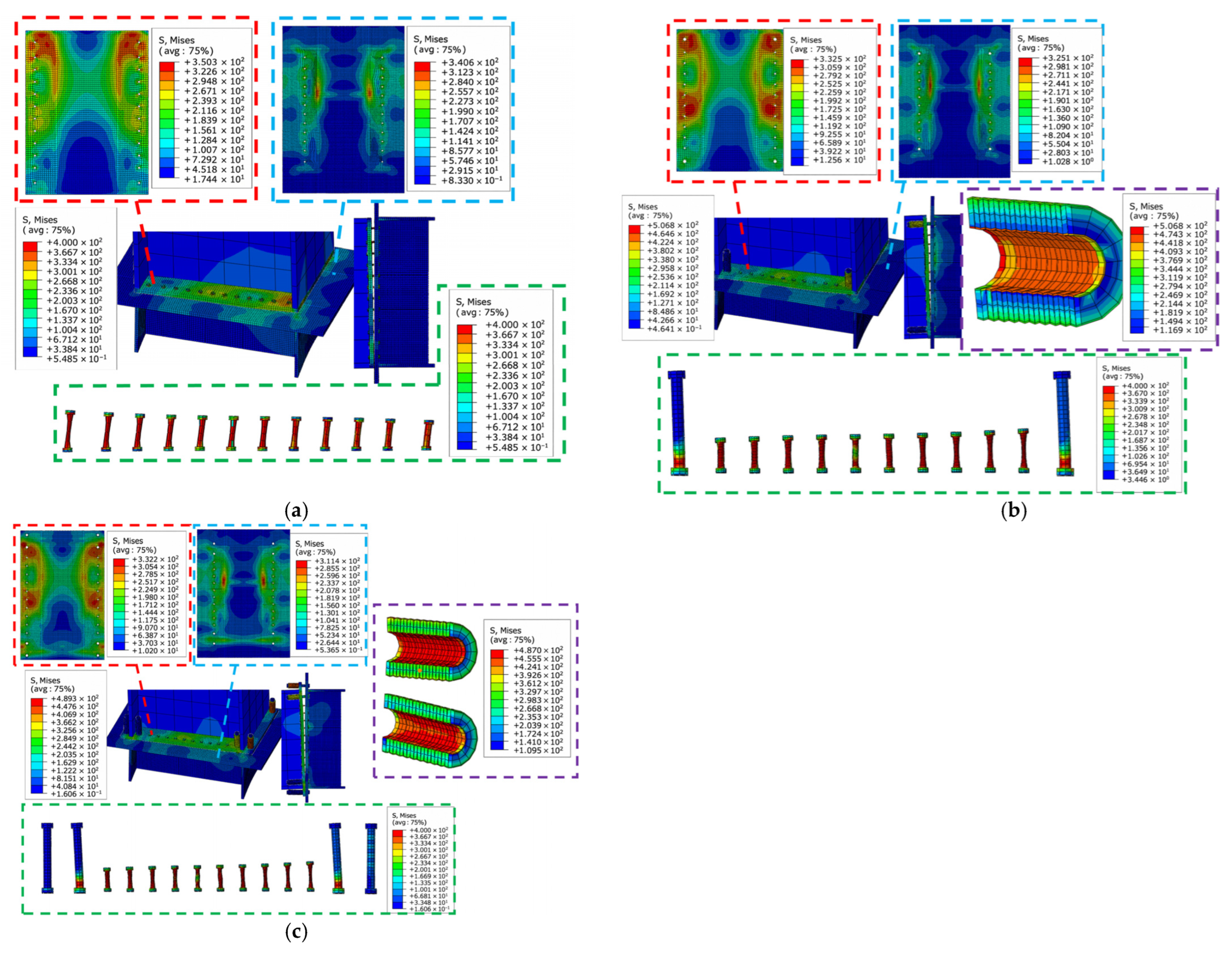
Figure 6 compares the von Mises stress distributions of the three joint types at the peak displacement level. As shown in Figure 6a, the J-OB pad undergoes warping deformation, causing partial separation between the pad and the connecting plate. Under this condition, the fastening bolts in the critical region are subjected to relatively high stress, and the peak stress on one side of the pad reaches . Interface separation also induces bending in the connecting plate, producing a central stress concentration of .
Figure 6.
Comparison of von Mises stress distributions of the three joint configurations at peak displacement: (a) J-OB; (b) J-IS; (c) J-DS.
As shown in Figure 6b, replacing the edge bolts with SMA butterfly spring assemblies modifies the interface opening–closing behavior and changes the load transfer path within the joint. The peak stress in the pad plate decreases to , corresponding to a modest reduction, while the peak stress in the connecting plate is reduced to , corresponding to a modest reduction. These stress reductions indicate only a minor trend of local stress redistribution rather than a significant strength-related improvement. The SMA component reaches a stress of approximately in the finite element analysis, while the modified load transfer path increases the demand on the SMA anchorage bolts and adjacent plates.
As shown in Figure 6c, the stress distribution pattern of the dual-row SMA joint is similar to that of the single-row system, but the load distribution is more uniform. The maximum stress in the connecting plate is further reduced to , representing a modest decrease relative to the single-row system. This small difference suggests a possible load-sharing tendency in the dual-row arrangement. The two SMA rows work collaboratively and limit the maximum SMA stress to . The outer SMA anchor bolts exhibit a distinct stress pattern: they are governed primarily by the axial demand induced by SMA extension and contribute less to the overall rotational response of the joint.
These results indicate two main trends:
- (1)
- Relative to the non-SMA reference joint, the SMA-enabled configurations show a modest reduction in the peak stress of the key plates, with reductions of approximately 4.7–4.9%, indicating a tendency toward local stress redistribution associated with the SMA-enabled detailing.
- (2)
- The dual-row layout further reduces the peak stress of the connecting plate by approximately , indicating that the increased use of SMA butterfly spring devices contributes to a load-sharing tendency.
4.1.2. Cumulative Plastic Strain Distribution
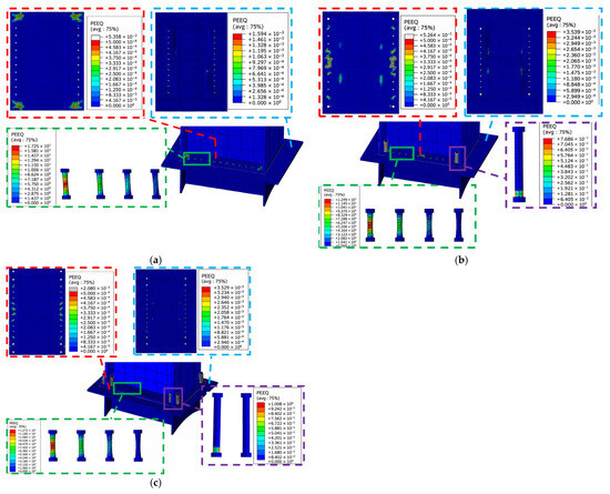
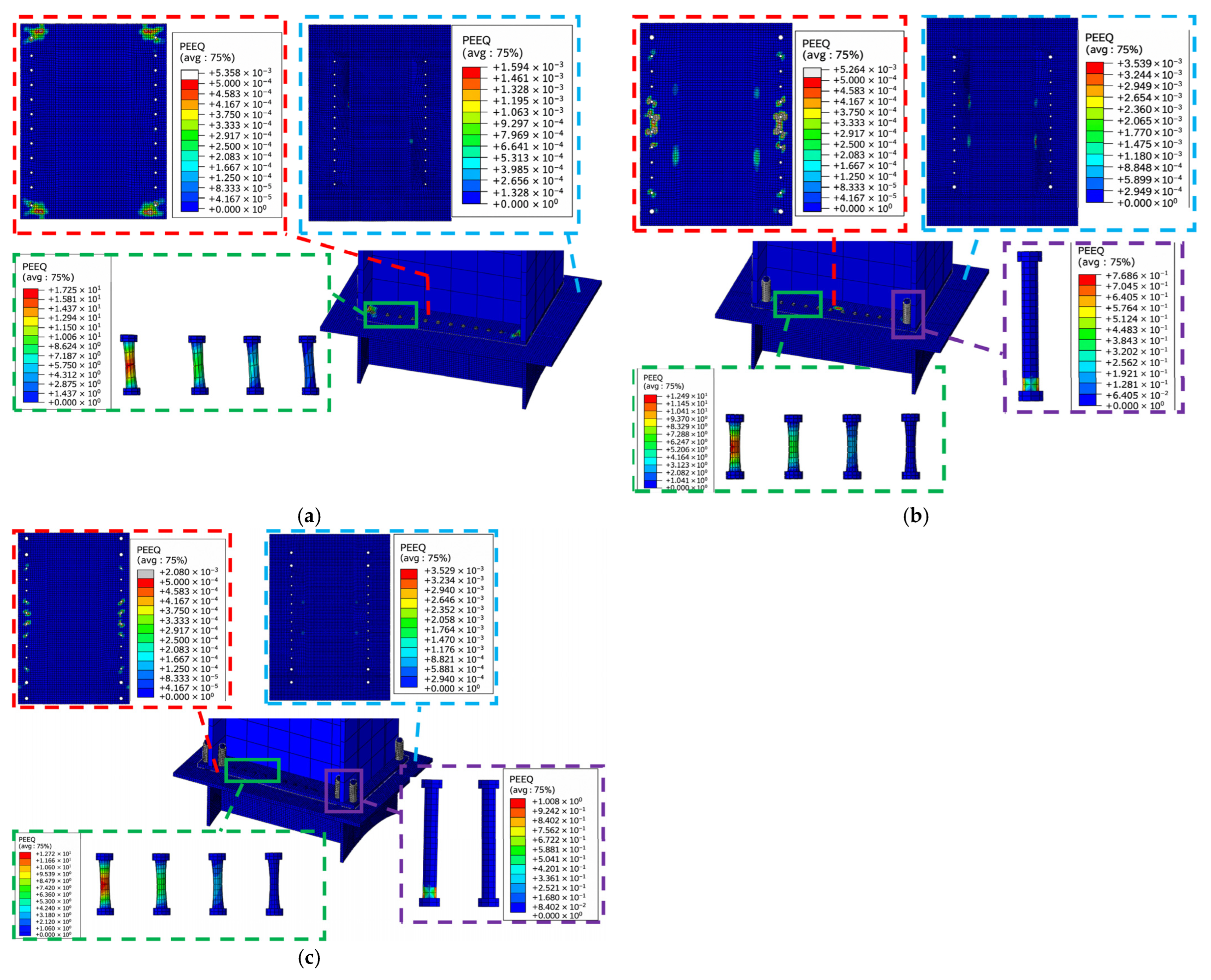
Figure 7 compares the equivalent plastic strain (PEEQ) distributions of the three joints under cyclic loading. The PEEQ distribution of the non-SMA reference joint exhibits clear localization near the outer bolt region (Figure 7a). During cyclic loading, the outermost bolts show the most pronounced local plastic accumulation, with a raw peak PEEQ value of . Because ductile damage and fracture were not included in the present models, this high local value should be interpreted as an indicator of severe plastic localization rather than as a physically admissible fracture-free strain of the bolt. Along the longitudinal direction of the tie beam pad, the PEEQ level decreases gradually and becomes nearly zero near the fourth bolt. By contrast, the connecting components remain at a relatively low PEEQ level.
Figure 7.
Comparison of equivalent plastic strain (PEEQ) distributions obtained from the no-fracture finite element models: (a) J-OB; (b) J-IS; (c) J-DS.
As shown in Figure 7b, the peak PEEQ indicator in the single-row SMA joint decreases to 12.49, representing a reduction relative to the non-SMA reference joint within the same no-fracture modeling framework, while the overall localization pattern still follows a similar gradient distribution. This comparison is used to describe the relative severity of local plastic localization, not to assess the fracture safety of the bolts. The opening–closing amplitude between the pad and the connecting plate increases, and the concentrated plastic localization zone shifts from the edge toward the middle region. In addition, local PEEQ accumulation appears in the lower region of the long bolt connected to the SMA butterfly spring, with a reported value of 0.77, which is much lower than that observed in the ordinary bolts.
As shown in Figure 7c, the overall cumulative plastic strain pattern of the dual-row SMA joint is similar to that of the single-row SMA joint. In contrast to the inner long bolts connected to the SMA butterfly springs, the outer long bolts remained elastic throughout loading and did not exhibit cumulative plastic damage.
The comparison indicates that:
- (1)
- Changes in the opening and closing amplitude of the tie beam pad alter the location of local plastic accumulation.
- (2)
- Within the adopted no-fracture finite element framework, the introduction of SMA components reduced the relative peak PEEQ indicator by , thereby alleviating the plastic localization tendency observed in the non-SMA reference joint.
4.2. Analysis of Energy Dissipation Capacity
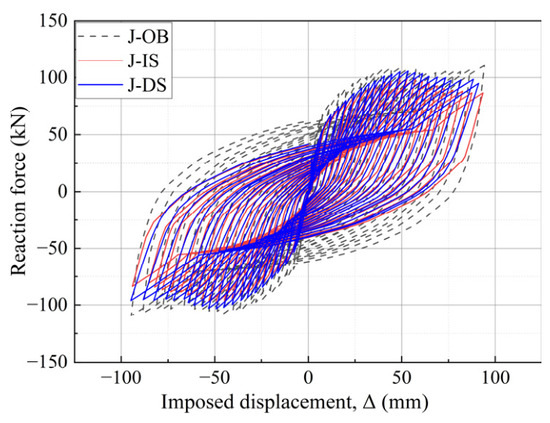
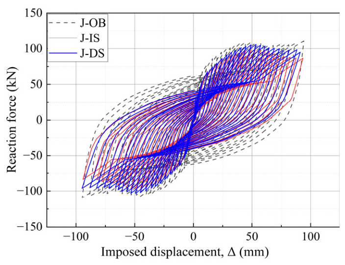
Figure 8 presents the force–displacement hysteresis loops of the three joint types. Under the adopted contact modeling scheme, the non-SMA reference joint exhibits fuller, nearly spindle-shaped loops, indicating higher cumulative hysteretic energy dissipation. Both SMA-enabled joints exhibit closed but more pinched loops under the adopted single-cycle protocol, indicating lower overall hysteretic energy than J-OB but a clearer self-centering tendency. Within the SMA configurations, J-DS exhibits a fuller loop than J-IS, suggesting slightly higher energy dissipation due to greater device participation. The recovery branch of the SMA loops is consistent with superelastic recovery and is associated with residual deformation control.
Figure 8.
Force–displacement hysteresis loops of the three joint types (J-OB, J-IS, and J-DS).
4.3. Backbone Response Analysis
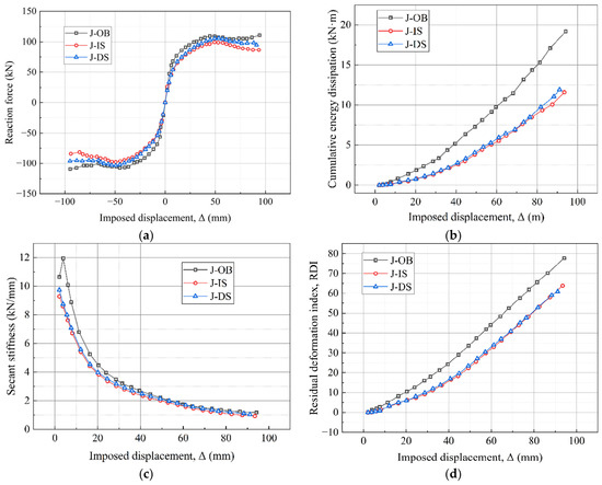
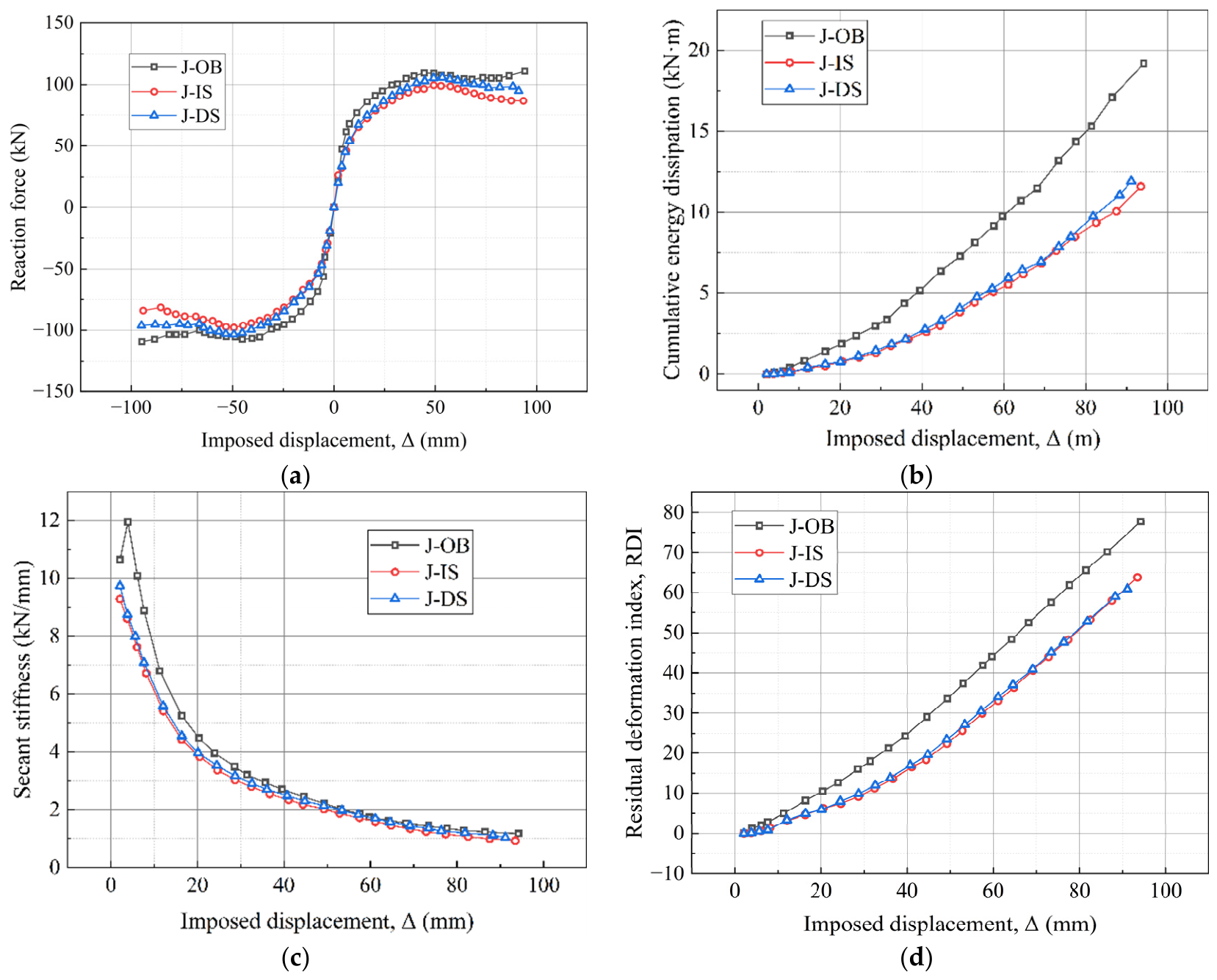
The backbone curve is obtained by connecting the peak points of each hysteresis loop (Figure 9a). All joints exhibit a typical S-shaped backbone response, indicating similar nonlinear force–displacement evolution. Overall, J-OB develops slightly higher reaction forces than the SMA joints, with differences remaining within . For example, at , J-OB reaches , about higher than J-DS (); at , J-OB reaches , about higher than J-DS ().
Figure 9.
Comparison of joint-level response metrics of the three joint configurations: (a) backbone curves; (b) cumulative energy dissipation; (c) secant stiffness variation; (d) residual deformation index (RDI, %) and imposed displacement curves.
Within the SMA configurations, J-DS exhibits higher reaction force than J-IS, with the difference remaining within : at , J-DS () is higher than J-IS (), and at , J-DS () is higher than J-IS (). All joints remain nearly elastic within , after which stiffness degradation becomes evident. J-OB reaches a peak capacity of at , while J-DS and J-IS reach and at , respectively. These results indicate a joint-level design trade-off under the adopted modeling framework: J-OB develops slightly higher strength and cumulative hysteretic energy dissipation, whereas the SMA-enabled joints exhibit lower dissipation but provide improved damage localization and self-centering tendency.
4.4. Cumulative Energy Dissipation Analysis
Cumulative energy dissipation was quantified from the accumulated enclosed area of the force–displacement hysteresis loops (Figure 9b) using numerical integration of the discrete loop data. Under the adopted contact modeling scheme, J-OB exhibits the largest cumulative hysteretic energy among the three models. This response is associated with the combined effects of interface opening/closing, bolt–plate bearing interaction, and localized plasticity around the contact regions. At the displacement level used for comparison, the cumulative energy dissipation of J-DS is , which is lower than that of J-OB (). This difference is, therefore, interpreted as a joint-level hysteretic response difference under the present numerical framework. The SMA-enabled joints are not intended to act as maximum dissipation devices; rather, their main function is to provide restoring capability, reduce residual deformation, and redirect inelastic demand toward replaceable bolt/spring subassemblies. Within the SMA configurations, J-DS dissipates about more energy than J-IS at (), because the additional SMA row increases device participation during joint rotation. This behavior is consistent with the superelastic transformation plateau: greater SMA engagement can moderately increase energy dissipation, but the overall hysteretic response remains governed by the self-centering phase transformation mechanism.
4.5. Stiffness Degradation Analysis
Because only one cycle was applied at each displacement amplitude, the stiffness response discussed here refers to the displacement amplitude-dependent variation in secant stiffness extracted from the one-cycle response, rather than to cycle-to-cycle degradation under repeated loading at the same amplitude. The finite element results show that all three joint types exhibit a gradual reduction in secant stiffness with increasing displacement amplitude, as illustrated in Figure 9c. The following trends can be observed:
- (1)
- J-OB consistently exhibited a secant stiffness that was 0.2–1.1 kN/mm higher than that of the two SMA joints, reflecting the higher initial restraint of the non-SMA reference configuration under the adopted modeling framework.
- (2)
- Despite its higher initial stiffness, the bolted joint exhibited a faster reduction in secant stiffness with increasing displacement amplitude than the SMA joints, with the calculated reduction rate being about higher. This trend is associated with greater local plastic accumulation at the connection interface under the present single-cycle numerical protocol.
- (3)
- The stiffness degradation curves of the dual-row and single-row SMA joints are very similar. The maximum difference in stiffness between them was only , suggesting that the number of SMA components has a limited influence on the stiffness degradation path.
Although the SMA-enabled joints dissipate less cumulative energy than J-OB, the backbone response and secant stiffness results indicate that this reduction is not accompanied by an abrupt loss of joint resistance within the analyzed displacement range. The peak reaction forces of J-DS and J-IS remain comparable to that of J-OB, and the SMA-enabled joints exhibit a more gradual secant stiffness reduction with increasing displacement amplitude. Therefore, at the joint component level, the reduced cumulative dissipation should be interpreted together with the maintained lateral resistance, reduced plastic localization tendency, and improved residual deformation control under the adopted loading protocol.
4.6. Residual Deformation Response
For double-column pier bents, limiting residual displacement is critical for rapid post-earthquake reopening; therefore, residual deformation is evaluated using the residual deformation index ():
where is the residual displacement extracted when the reaction force returns to zero during unloading at each loading level, and is the reference yield displacement. In this study, was taken as 15 mm according to the backbone response, where the three joint models remained approximately elastic within and then showed evident secant stiffness reduction. The absolute value of was used, so the RDI curves in Figure 9d represent the positive residual deformation envelope.
The residual deformation results are shown in Figure 9d. For all three joints, the RDI increases with displacement amplitude and becomes more pronounced beyond , indicating sustained accumulation of irreversible deformation at the interface. The SMA-enabled joints show lower residual deformation than the non-SMA reference joint. At the maximum displacement level, the RDI values of J-DS, J-IS, and J-OB are , , and , respectively. Based on the reference yield displacement , these values correspond to residual displacements of approximately , , and . Therefore, J-DS reduces the RDI by about relative to J-OB. The single-row SMA joint exhibits an intermediate residual deformation level, suggesting that greater SMA engagement improves the re-centering tendency under the adopted numerical framework.
This behavior can be attributed to two coupled mechanisms and becomes more evident at larger amplitudes (), where plasticity-induced irreversibility becomes more pronounced in the non-SMA reference joint. First, the superelastic response of the SMA provides restoring force during unloading, which counteracts permanent deformation and limits irreversible rotation. Second, the proposed joint detailing redirects inelastic demand away from hard-to-repair welded regions and concentrates plastic strain in replaceable bolt/device subassemblies, thereby reducing damage propagation into the primary load-bearing components. In contrast, the larger hysteretic energy observed in J-OB is accompanied by repeated interface opening/closing, bolt–plate bearing interaction, and localized plasticity at the contact regions, which are associated with greater irreversible deformation and larger residual displacement after cycling.
Overall, the proposed SMA butterfly spring joint should be interpreted as a repair-oriented connection concept. Under the adopted numerical modeling framework, it provides improved self-centering tendency, damage localization in replaceable components, and reduced residual deformation, although its cumulative interface-induced dissipation is lower than that of the non-SMA reference joint.
4.7. Design Implications and Repair-Oriented Interpretation
The above results indicate that the proposed SMA butterfly spring joint should not be evaluated solely by cumulative energy dissipation. Compared with J-OB, the SMA-enabled joints show lower cumulative hysteretic energy dissipation, but they also reduce plastic damage concentration and residual deformation. This behavior reflects a design trade-off between cumulative energy dissipation and joint-level residual deformation control.
From a joint component perspective, the lower cumulative energy dissipation should not be evaluated independently of the maintained lateral resistance, stiffness-degradation trend, plastic damage distribution, and residual deformation response within the analyzed displacement range. The backbone curves show that the peak reaction forces of the SMA-enabled joints remain comparable to those of J-OB, while the stiffness degradation results indicate a more gradual degradation trend. In addition, the RDI of J-DS is reduced by about relative to J-OB, which corresponds to a reduction in residual displacement from approximately to based on . This trend is beneficial for post-earthquake inspection and repair.
Overall, the present study provides a joint component-level finite element comparison of three bolted joint configurations under a unified modelling framework. The comparison focuses on how the proposed fuse region design and SMA butterfly spring layout influence plastic strain redistribution, hysteretic response, cumulative energy dissipation, and residual deformation. Future work will extend the present joint-level analysis through calibrated subassembly tests, member-level capacity checks, and bridge system-level seismic evaluation to support practical design recommendations.
5. Conclusions
This study proposed a repair-oriented steel tie beam joint with SMA butterfly springs for double-column piers and evaluated its cyclic behavior through finite element simulations. Compared with the non-SMA bolted reference joint (J-OB), the SMA-enabled joints (J-IS and J-DS) redirected inelastic demand toward replaceable bolt/spring subassemblies and improved residual deformation control at the joint component level. The main conclusions are as follows.
- (1)
- SMA butterfly springs modified the local stress distribution in key connection plates. Relative to J-OB, J-IS showed a modest peak stress reduction of about 4.7–4.9%. Within the SMA configurations, the dual-row arrangement further reduced the peak stress in the connecting plate from to and lowered the maximum SMA stress demand from about to . These results indicate a tendency toward local stress redistribution rather than a substantial improvement in strength.
- (2)
- The SMA joints modified the local plastic strain distribution in critical connection regions. Within the adopted no-fracture finite element framework, the raw peak PEEQ indicator decreased from 17.25 in J-OB to 12.49 in J-IS, corresponding to a relative reduction of . These high local PEEQ values were interpreted as indicators of plastic localization rather than as fracture-free strain capacities of the bolts. In J-DS, the outer long bolts remained elastic throughout loading and did not exhibit cumulative plastic accumulation.
- (3)
- J-OB exhibited higher cumulative hysteretic energy, whereas the SMA joints showed more pinched hysteretic loops with a clearer self-centering tendency under the adopted loading protocol. At the reported comparison point, the cumulative energy dissipation of J-DS was lower than that of J-OB. This value represents a difference in joint-level hysteretic loop area under the adopted numerical framework and should not be interpreted as a calibrated comparison of frictional energy dissipation. Therefore, the proposed SMA-enabled joints should not be regarded as maximum-dissipation devices. Within the SMA configurations, J-DS provided about higher cumulative energy dissipation than J-IS at , suggesting that greater SMA engagement can moderately improve dissipation while maintaining self-centering behavior.
- (4)
- The SMA joints provided improved residual deformation control under the adopted numerical framework. At the maximum displacement level, the RDI values of J-DS and J-OB were and , respectively, corresponding to a reduction of about . With the reference yield displacement , the corresponding residual displacements were approximately and . This result indicates that the proposed detail has potential for improving joint-level residual deformation control and facilitating post-earthquake inspection and repair.
Overall, the proposed SMA butterfly spring joint is not intended to maximize strength or cumulative energy dissipation but to provide a repair-oriented and low-damage connection concept for double-column piers. The present finite element results indicate its potential in damage localization and residual deformation control under a unified contact modeling framework. Further calibrated subassembly tests, bolt interface studies, and bridge system-level analyses are still needed to quantify bolt removal feasibility after hole deformation, retained-plate serviceability, and recovered cyclic performance after component replacement.
Author Contributions
Conceptualization, Z.W.; methodology, Z.M.; software, H.Z.; validation, S.J. and Y.H.; formal analysis, Z.M. and H.Z.; investigation, J.Z., S.J. and Y.F.; resources, Y.F.; data curation, J.Z.; writing—original draft preparation, Z.M.; writing—review and editing, Z.W. and J.Z.; visualization, J.Z. and Y.H.; supervision, Z.W.; project administration, Z.W.; funding acquisition, Z.W. All authors have read and agreed to the published version of the manuscript.
Funding
This research was funded by the Sichuan Natural Science Foundation under the project “Research on the Random Seismic Response Analysis Method of Curvilinear Isolated Girder Bridges” (Grant No. 2024NSFSC0171).
Institutional Review Board Statement
Not applicable.
Informed Consent Statement
Not applicable.
Data Availability Statement
The data presented in this study are available from the corresponding author upon reasonable request.
Conflicts of Interest
The authors declare no conflicts of interest. The funders had no role in the design of the study; in the collection, analyses, or interpretation of data; in the writing of the manuscript; or in the decision to publish the results.
References
- McCormick, J.; Aburano, H.; Ikenaga, M.; Nakashima, M. Permissible residual deformation levels for building structures considering both safety and human elements. In Proceedings of the 14th World Conference on Earthquake Engineering, Beijing, China, 12–17 October 2008. [Google Scholar]
- Xie, L.; Sha, H.; Chong, X.; Jia, J. Seismic performance comparison between reinforced concrete frame structures with and without energy dissipating cladding panel system: Shaking table test and numerical simulation. J. Build. Eng. 2022, 62, 105414. [Google Scholar] [CrossRef] [Scilit]
- Long, X.; Chen, Z.; Li, P. Seismic performance of corroded ecc-gfrp spiral-confined reinforced-concrete column. Polymers 2024, 16, 2110. [Google Scholar] [CrossRef] [Scilit] [PubMed]
- Rinaldin, G.; Amadio, C.; Fragiacomo, M. Effects of seismic sequences on structures with hysteretic or damped dissipative behaviour. Soil Dyn. Earthq. Eng. 2017, 97, 205–215. [Google Scholar] [CrossRef] [Scilit]
- Oyguc, E.; Oyguc, R.; Hayir, A.; Seker, O.; Shen, J.; Akbas, B. Seismic retrofitting of substandard rc frames using tube-in-tube buckling-restrained braces: Shake table evaluation and field insights. Bull. Earthq. Eng. 2025, 23, 4565–4608. [Google Scholar] [CrossRef] [Scilit]
- Eilbeigi, S.; Tavakkolizadeh, M.; Masoodi, A.R. Enhancing mechanical behavior and energy dissipation in fiber-reinforced polymers through shape memory alloy integration: A numerical study on sma-frp composites under cyclic tensile loading. Materials 2023, 16, 5695. [Google Scholar] [CrossRef] [Scilit] [PubMed]
- Zhan, M.; Liu, J.; Wang, D.; Chen, X.; Zhang, L.; Wang, S. Optimized neural network prediction model of shape memory alloy and its application for structural vibration control. Materials 2021, 14, 6593. [Google Scholar] [CrossRef] [Scilit] [PubMed]
- Chancellor, N.; Eatherton, M.; Roke, D.; Akbaş, T. Self-centering seismic lateral force resisting systems: High performance structures for the city of tomorrow. Buildings 2014, 4, 520–548. [Google Scholar] [CrossRef] [Scilit]
- DesRoches, R.; Smith, B. Shape memory alloys in seismic resistant design and retrofit: A critical review of their potential and limitations. J. Earthq. Eng. 2004, 8, 415–429. [Google Scholar] [CrossRef] [Scilit]
- DesRoches, R.; McCormick, J.; Delemont, M. Cyclic properties of superelastic shape memory alloy wires and bars. J. Struct. Eng. 2004, 130, 38–46. [Google Scholar] [CrossRef] [Scilit]
- Roh, H.; Reinhorn, A.M. Hysteretic behavior of precast segmental bridge piers with superelastic shape memory alloy bars. Eng. Struct. 2010, 32, 3394–3403. [Google Scholar] [CrossRef] [Scilit]
- Liew, K.M.; Kitipornchai, S.; Ng, T.Y.; Zou, G.P. Multi-dimensional superelastic behavior of shape memory alloys via nonlinear finite element method. Eng. Struct. 2002, 24, 51–57. [Google Scholar] [CrossRef] [Scilit]
- Sultana, P.; Youssef, M.A. Seismic performance of steel moment resisting frames utilizing superelastic shape memory alloys. J. Constr. Steel Res. 2016, 125, 239–251. [Google Scholar] [CrossRef] [Scilit]
- Dolce, M.; Cardone, D.; Marnetto, R. Implementation and testing of passive control devices based on shape memory alloys. Earthq. Eng. Struct. Dyn. 2000, 29, 945–968. [Google Scholar]
- Ocel, J.; DesRoches, R.; Leon, R.T.; Hess, W.G.; Krumme, R.; Hayes, J.R.; Sweeney, S. Steel beam-column connections using shape memory alloys. J. Struct. Eng. 2004, 130, 732–740. [Google Scholar] [CrossRef] [Scilit]
- Speicher, M.S.; DesRoches, R.; Leon, R.T. Experimental results of a niti shape memory alloy (sma)-based recentering beam-column connection. Eng. Struct. 2011, 33, 2448–2457. [Google Scholar] [CrossRef] [Scilit]
- Abolmaali, A.; Treadway, J.; Aswath, P.; Lu, F.K.; McCarthy, E. Hysteresis behavior of t-stub connections with superelastic shape memory fasteners. J. Constr. Steel Res. 2006, 62, 831–838. [Google Scholar] [CrossRef] [Scilit]
- Ma, H.; Wilkinson, T.; Cho, C. Feasibility study on a self-centering beam-to-column connection by using the superelasticbehavior of smas. Smart Mater. Struct. 2007, 16, 1555. [Google Scholar] [CrossRef] [Scilit]
- Yam, M.C.; Fang, C.; Lam, A.C.; Zhang, Y. Numerical study and practical design of beam-to-column connections with shape memory alloys. J. Constr. Steel Res. 2015, 104, 177–192. [Google Scholar] [CrossRef] [Scilit]
- Dou, C.; Ru, Y.; Xu, L. Cyclic loading behavior of earthquake-resilient disc-spring self-centering beam-column joints: An experimental study. Eng. Struct. 2025, 335, 120366. [Google Scholar] [CrossRef] [Scilit]
- Akbarnezhad, M.; Salehi, M.; DesRoches, R. Seismic design and numerical assessment of shape memory alloy-restrained rocking precast concrete bridge columns. Adv. Struct. Eng. 2022, 25, 2803–2829. [Google Scholar] [CrossRef] [Scilit]
- Katsimpini, P.; Papagiannopoulos, G.; Hatzigeorgiou, G. A thorough examination of innovative supplementary dampers aimed at enhancing the seismic behavior of structural systems. Appl. Sci. 2025, 15, 1226. [Google Scholar] [CrossRef] [Scilit]
- Chen, S.; An, W.; Fu, H.; Shan, Y.; Xi, F.; Wen, Y.; Nazri, F.M.; Chin, C.; Ma, C. Review of dynamic response and pier damage mechanisms in girder bridges under bidirectional seismic excitations: Critical role of vertical components in near-field effects. Buildings 2025, 15, 4393. [Google Scholar] [CrossRef] [Scilit]
- Rahman, J.; Billah, A.H.M.M. Seismic performance evaluation of shape memory alloy (sma) reinforced concrete bridge bents under long-duration motion. Front. Built Environ. 2020, 6, 601736. [Google Scholar] [CrossRef] [Scilit]
- Oyguc, R.; Bozan, A.B. Enhancing seismic repairability of precast rc frames through an innovative replaceable plastic hinge technology. Appl. Sci. 2025, 15, 5629. [Google Scholar] [CrossRef] [Scilit]
- Neupane, S.; Pantelides, C.P. Seismic design and fragility of self-centering bridge bent with replaceable stretch length anchors. Earthq. Eng. Struct. Dyn. 2025, 54, 1433–1453. [Google Scholar] [CrossRef] [Scilit]
- Chen, J.; Liang, D.; You, X.; Liang, H. Performance-based assessment of bridges with novel sma-washer-based self-centering rocking piers. Materials 2022, 15, 6589. [Google Scholar] [CrossRef] [Scilit] [PubMed]
- Qian, H.; Ye, Y.; Yan, C.; Jin, G.; Li, C.; Shi, Y. Experimental study on the seismic performance of self-centering bridge piers incorporating ecc and superelastic sma bars in the plastic hinge regions. Structures 2022, 46, 1955–1967. [Google Scholar] [CrossRef] [Scilit]
- Huynh, T.; Dang, N.; Kim, J. Preload monitoring in bolted connection using piezoelectric-based smart interface. Sensors 2018, 18, 2766. [Google Scholar] [CrossRef] [Scilit] [PubMed]
- Auricchio, F.; Taylor, R.L. Shape-memory alloys: Modelling and numerical simulations of the finite-strain superelastic behavior. Comput. Methods Appl. Mech. Eng. 1997, 143, 175–194. [Google Scholar] [CrossRef] [Scilit]
- Huang, J.; Zhao, H.; Gao, Y.; Shi, G. Finite element analysis and design of triple grades hybrid high-performance steel structure (tghss). Eng. Struct. 2025, 330, 119909. [Google Scholar] [CrossRef] [Scilit]
- Huang, J.; Zhao, H.; Gao, Y.; Shi, G. Numerical study on cyclic behaviour of triple grades hybrid high-performance steel structure. Eng. Struct. 2025, 327, 119605. [Google Scholar] [CrossRef] [Scilit]
- Shi, G.; Hou, L.; Zhao, H. Numerical study on the seismic behaviour of high-strength steel moment-resisting frames: Multi-scale modelling and validation. Thin-Walled Struct. 2025, 208, 112807. [Google Scholar] [CrossRef] [Scilit]
- Ahmadi, H.M.; De Matteis, G. Cyclic behaviour of steel shear walls with beam-only connection shear panels. In Proceedings of the 10th International Conference on Behaviour of Steel Structures in Seismic Areas; Lecture Notes in Civil Engineering; Springer: Cham, Switzerland, 2022; pp. 659–666. [Google Scholar]
- Zhao, G.; Zhu, L.; Liu, W.; Zhao, J.; Huo, J. Numerical study on the effect of interface dynamic damage of steel–concrete composite beam bridge caused by high–frequency impact load. Buildings 2023, 13, 545. [Google Scholar] [CrossRef] [Scilit]
- Schwer, L.E. An overview of the ptc 60/v&v 10: Guide for verification and validation in computational solid mechanics. Eng. Comput. 2007, 23, 245–252. [Google Scholar] [CrossRef] [Scilit]
- Pisarciuc, C.; Dan, I.; Cioară, R. The influence of mesh density on the results obtained by finite element analysis of complex bodies. Materials 2023, 16, 2555. [Google Scholar] [CrossRef] [Scilit] [PubMed]
- Shi, G.; Zhang, N.; Bao, L.; Chen, X.; Zhou, F.; Jiang, S.; Zhao, H. Experimental investigation on local connection behaviour of thick-flange steel beam to cfst column joints under cyclic loadings. Eng. Struct. 2025, 343, 121206. [Google Scholar] [CrossRef] [Scilit]
- Shi, G.; Jiang, S.; Zhang, N.; Hou, L.; Zhao, H. Seismic performance of double-sided plate-reinforced connections between steel beams and built-up box columns. Thin-Walled Struct. 2025, 208, 112872. [Google Scholar] [CrossRef] [Scilit]
- Liu, L.; Lei, S.; Wu, F.; Lin, W.; Peng, K.; Fan, X. Experimental study on seismic performance of precast columns repaired with cfrp fabrics. Materials 2022, 15, 7443. [Google Scholar] [CrossRef] [Scilit] [PubMed]

Disclaimer/Publisher’s Note: The statements, opinions and data contained in all publications are solely those of the individual author(s) and contributor(s) and not of MDPI and/or the editor(s). MDPI and/or the editor(s) disclaim responsibility for any injury to people or property resulting from any ideas, methods, instructions or products referred to in the content. |
© 2026 by the authors. Licensee MDPI, Basel, Switzerland. This article is an open access article distributed under the terms and conditions of the Creative Commons Attribution (CC BY) license.