


Abstract
The use of recycled aggregate concrete (RAC) enables the valorization of construction waste and supports carbon-reduction strategies. However, long-term service-induced deterioration means that recycled aggregates and their interfacial transition zones inevitably contain defects, which severely restrict the safe application of RAC in load-bearing structures. Notably, although RAC reduces embodied carbon by recycling construction waste, steel tube manufacturing introduces an additional carbon footprint; such carbon trade-offs can be well compensated by the improved structural efficiency and extended service life of steel-confined concrete, achieving superior whole-life carbon benefits. In the present study, a steel-tube-confined recycled aggregate concrete (STCRC) composite system is proposed. Through designed external confinement, the stress state of the internal concrete is altered from uniaxial compression to triaxial compression, thereby enhancing its axial load-bearing capacity. Axial compression tests were performed on 36 short column specimens of steel-tube-confined concrete (STCC) composed of C30 aggregate concrete and Q235 steel tubes with three wall thicknesses (4.5 mm, 6 mm, 8 mm). Further parametric finite element analyses with 16 calculation cases were conducted to quantify the effects of higher concrete strength grades (C40 and C50) and of steel tube strength grades. The evolutionary characteristics of the load-displacement response, the axial stress–lateral strain relation, and the lateral strain–longitudinal strain were systematically investigated across various parameters. Test outcomes indicate that steel tube confinement significantly restrains lateral dilation of RAC and enhances its ductility and ultimate bearing capacity, with higher confinement efficiency observed for RAC than for natural aggregate concrete (NAC). Numerical results further identify the differing sensitivities of NAC and RAC to variations in tube wall thickness, steel yield strength, and concrete strength grade. Using combined experimental and numerical datasets, a peak stress modification factor is proposed, and a tailored stress–strain constitutive model for STCRC is developed and validated. The research findings provide theoretical guidance for the design of axially compressed short columns made of prefabricated recycled concrete.
1. Introduction
Construction waste is a major contributor to global energy consumption and one of the most significant waste streams. According to recent statistics, construction and demolition waste (CDW) accounts for approximately 35% of the total solid waste generated worldwide [1], with annual CDW generation across 40 countries exceeding four billion tons [2]. China, the European Union, and the United States contribute about 2.0 billion tons, 0.45 billion tons, and 0.54 billion tons, respectively [3]. Moreover, driven by ongoing economic development and urbanization, the volume of CDW is expected to increase exponentially in the coming years [4,5,6,7]. Conventional disposal of concrete waste relies mainly on landfilling or stockpiling, practices that not only consume valuable land resources but also cause severe contamination of soil and groundwater [8]. To address this issue, proper management of construction waste has been proposed, typically involving crushing, sorting, washing, and particle-size classification to convert waste concrete into recycled aggregates. When such aggregates are used as the primary raw material to produce recycled aggregate concrete (RAC) [9] and subsequently reused in construction projects, this approach can effectively mitigate environmental pollution at the source, reduce natural resource consumption, and yield notable ecological benefits [10]. Consequently, RAC is recognized as a key technology for promoting the resource-efficient utilization of construction waste and facilitating the low-carbon transformation of the building sector. At present, the application of RAC is mainly limited to non-load-bearing structural components, small precast elements, and road construction works.
RAC replaces natural aggregates with recycled solid waste aggregates, reducing the consumption of natural sand and stone resources and lowering carbon emissions. However, the high variability in its mechanical properties, the complexity of its constitutive relationships, and the unpredictability of its structural behavior still restrict its large-scale engineering application [11]. Multiple studies have indicated that the degradation in mechanical performance of RAC is mainly attributed to the poor internal quality of recycled aggregates (RA), the weakness of the interfacial transition zone (ITZ), and the high susceptibility to microcracking [12,13,14]. Because recycled concrete aggregates possess higher porosity and residual old mortar adhering to their surfaces, this old mortar leads to greater variability and water absorption in RAC and significantly weakens the ITZ within the concrete. Consequently, RAC exhibits lower strength, poorer mechanical interlocking between aggregates and cementitious materials, and inferior durability compared with natural aggregate concrete. Under the combined influence of these factors, most RAC is currently used only in non-structural components and rarely in projects requiring high strength, high durability, or large-scale construction. To address the above degradation mechanisms, academic and engineering communities have proposed material-level modification and rehabilitation techniques, mainly focusing on aggregate surface modification, ITZ strengthening, and self-healing functionalization. Li et al. [15] applied a composite impregnation treatment to RAC using a sodium silicate solution and a silane slurry. They analyzed the surface changes in the modified RAC using scanning electron microscopy. Their results showed that the modification method effectively improved RAC performance. Lu et al. [16] used graphene oxide (GO)-adsorbed recycled fine aggregate (RFA) particles to reinforce the interfacial gap between recycled fine aggregates and the paste. Experimental results indicated that incorporating WGO@RFA increased the 28-day compressive and flexural strengths of recycled mortar by 25% and 20%, respectively. Wang et al. [17] used recycled concrete fine aggregate (RCA) as a microbial carrier to investigate the synergistic enhancement of crack healing by magnesium ions. Their results showed that at a Ca/Mg molar ratio of 3, the mineralization efficiency reached 31.1%, and the 28-day crack repair rate reached 97.8%. Although the above studies have been effective in improving the physical, mechanical, and durability properties of RAC, these methods still suffer from drawbacks, including high cost, limited applicability, and modest performance gains. For instance, techniques such as nanomaterial soaking and microbial cultivation are simple and cost-controllable in the laboratory, but when scaled up to industrial sites, high material costs and complex process flows make it difficult to achieve on-site real-time modification [18]. High-temperature carbonation modification requires specialized equipment and may affect aggregate strength [19]. Although microbial self-healing holds promise, maintaining the long-term survival and activity of viable bacteria within concrete remains a challenge. Moreover, this method has mainly been validated on small laboratory specimens; for large-volume structures, the requirements for permeability and curing conditions are stringent, making it difficult to achieve the expected improvement [20]. Therefore, to enable large-scale utilization of construction solid waste, further investigation is still needed into reinforcement methods for RAC that are suitable for engineering applications.
In addition to modifying RAC at the material level, optimizing its performance from the perspectives of structural design and mechanical confinement represents another effective approach. To mitigate the brittle failure of concrete under axial compression, steel-tube-confined concrete (STCC) members have been designed to transform the stress state from uniaxial to triaxial compression, thereby effectively enhancing the structural strength of concrete [21]. Compared with material-level optimization methods such as aggregate modification and interfacial strengthening, this structural-level reinforcement method achieves more pronounced effects. It is more suitable for large-scale strengthening of RAC and its broader engineering applications. Researchers have proposed various forms of steel tube confinement and investigated the axial compressive behavior of recycled-aggregate concrete-filled steel tubes. Geng et al. [22] placed RAC inside steel tubes to form a composite structure of recycled aggregate concrete-filled steel tubes, utilizing the confinement provided by the outer steel tube to overcome the performance drawbacks of RAC caused by cementitious groups adhering to the surface of recycled coarse aggregates and internal cracks generated during the crushing process. This approach offers broad prospects for the practical application of RAC in structural engineering. Deng et al. [23] experimentally and theoretically studied the axial compressive deformation behavior of concrete-filled steel tubes (CFSTs). Their results indicated that CFSTs exhibit superior compressive performance, although the confinement efficiency decreases when high-strength concrete is used. Yang et al. [24] conducted experimental investigations and finite element simulations on CFSTs under axial compression. Their findings showed that when the slenderness ratio or axial compression ratio of the member is relatively high, the steel tube is prone to buckling or local buckling, leading to a severe reduction in load-bearing capacity. According to the above studies, although CFST columns can significantly enhance the load-bearing capacity and ductility of the core concrete through lateral confinement, the confinement effect markedly decreases after the steel tube yields under axial compression. As the axial load increases, the member’s lateral deformation intensifies, readily inducing local buckling of the steel tube and thereby severely weakening its confinement effect on the core RAC. Therefore, to achieve more efficient and durable confinement of RAC, more advanced external confinement methods warrant further investigation.
To address the above issues, Zhou et al. [25] proposed a novel STCC configuration in which the steel tube confines the core concrete without sustaining longitudinal loads, thereby exerting a purely circumferential constraint on the concrete and enhancing its mechanical confinement. Their results showed that the STCC structure exhibits superior axial compressive performance compared with conventional CFST, demonstrating clear advantages. Xiao et al. [26,27] conducted experimental studies on the axial mechanical behavior of RAC confined by steel tubes. Their investigations revealed that, for STCC, the assumptions of constant or elastic–plastic confinement are not applicable, and the replacement ratio of RAC has a moderate influence on the mechanical response of the confined concrete. Qiu et al. [28] adopted a finite element analysis method for STCC, supplemented by a concrete-steel interaction model. They derived approximate expressions for the descending branch slope of the compressed concrete in columns with various cross-section types, as well as for the strain at sustained concrete strength. Megahed K et al. [29,30] carried out a series of axial compression tests on short STCC specimens. Their tests indicated that STCC columns exhibit extremely high energy dissipation and ductility when subjected to high axial loads; moreover, the confining interaction between the steel tube and the core concrete, as well as the ultimate strength of locally loaded STCC specimens, decreases with an increase in the diameter-to-thickness ratio of the steel tube. Li et al. [31] established a refined finite element model to systematically investigate the confinement mechanism of STCC stub columns under axial compression, revealing the stress distribution pattern across the stub columns’ cross-section and the evolution of the confinement provided by the steel tube to the core concrete. In summary, STCC successfully avoids the common problems of steel tube buckling and local instability observed in conventional CFST members, thereby significantly enhancing the confinement effect of the external steel tube on the core concrete [32,33]. However, existing research has mainly focused on the confinement behavior of conventional or high-strength concrete, paying less attention to the synergistic load-bearing performance of steel tube confinement and recycled aggregate concrete. In-depth explorations remain lacking regarding the synergistic load-bearing mechanism, the quantitative analysis of expansion characteristics, and the microscopic mechanisms of steel-tube-confined RAC.
To systematically sort out the research progress, the main findings and inherent defects of existing studies related to recycled aggregate concrete strengthening and steel tube confinement are summarized in Table 1, so as to intuitively clarify the existing research gaps in this field.
Table 1.
Summary of previous relevant studies and research limitations.
This paper proposes a steel-tube-confined recycled concrete (STCRC) configuration, in which recycled concrete is placed as the core filler inside a steel tube, fully utilizing the confining effect of the steel tube to compensate for the macro- and micro-scale damage defects of recycled concrete, restrict its lateral expansion under compression, and significantly enhance the load-bearing capacity and deformation resistance of the core recycled concrete. Moreover, by converting the stress state of the core concrete from uniaxial compression to triaxial compression, the initiation and propagation of internal microcracks are delayed, the brittle failure mode of recycled concrete is mitigated, and the member’s ductility is increased. Furthermore, systematic experimental investigations, finite element analyses, and theoretical derivations are conducted to examine the expansion characteristics and the synergistic load-bearing mechanical mechanism of recycled concrete under external confinement. By varying the steel tube wall thickness, the influence patterns on macroscopic mechanical indicators such as peak load, longitudinal strain, and lateral expansion of the member are quantitatively analyzed. On this basis, using finite element numerical simulations, the parameter study is further extended to include concrete strength grade, steel tube wall thickness, and steel tube strength grade, thereby revealing the expansion mechanism and evolution laws of the core recycled concrete under different confinement conditions. Finally, an analysis-oriented constitutive model for the lateral expansion of STCRC is established, providing a theoretical basis for the mechanical performance analysis and engineering design of STCRC structures.
2. Experimental Program
2.1. Specimen Design
This study prioritizes the fundamental mechanical performance and parametric influence law of steel-tube-confined concrete (STCC) columns under ideal service conditions; therefore, the corrosion problem of steel tubes is not considered in the current test design. The specimens are strictly processed and stored in a standard indoor curing environment without exposure to corrosive media such as humidity, salt and acid, ensuring that all steel tubes maintain a non-corroded intact state before the test, which eliminates the interference of corrosion defects on the test results of structural mechanical properties. To comprehensively investigate the parametric influences on STCC structural performance, a total of 36 STCC columns in 6 groups were fabricated in this experiment. The main parameters investigated included steel tube strength, steel tube wall thickness, concrete type, and concrete strength grade. Three nominal cross-sectional dimensions were adopted for the outer steel tube: 180 × 4.5, 180 × 6, and 180 × 8 (mm). Three nominal cross-sectional dimensions were used for the outer hoop: 30 × 4.5, 30 × 6, and 30 × 8 (mm). The nominal cross-sectional dimensions of the inner concrete in all STCC specimens were 300 × 150 (mm). The curing period was 28 days, and the detailed configuration is illustrated in Figure 1. The designations N and R denote the first and second batches of specimens, respectively, with the first batch using natural concrete and the second using recycled concrete with a 100% replacement ratio. In the STCC specimen code, the first number indicates the nominal wall thickness of the outer steel tube; the number 30 represents the strength grade of the core concrete (C30); 235, 345, and 460 represent the yield strength of the outer steel tube; and the last digit is the specimen number within its group. Taking specimen N-4-30-235-1 as an example, N indicates the first batch (natural concrete), 4 indicates a nominal outer steel tube wall thickness of 4 mm, 30 indicates a core concrete strength grade of C30, 235 indicates a yield strength of Q235 for the outer steel tube, and 1 indicates the first specimen in its group. The detailed specimen parameters are listed in Table 2.
Figure 1.
Schematic diagram of STCC model components.
Table 2.
Specimen parameters.
2.2. Specimen Preparation
In this study, a total of 24 steel-tube-confined natural concrete specimens and 12 STCRC reference specimens were prepared. To fabricate the STCC specimens, the procedures outlined in the Code for Test of Steel Tube Confined Concrete and relevant literature were followed [34]. The mix proportions of C30 natural aggregate concrete (NAC) and 100% recycled aggregate concrete (RAC) adopted in this experiment are summarized in Table 3.
Table 3.
Mix proportions of tested concrete (kg/m3).
A combination of manual operations and mechanical processing was adopted to accurately process, fix, and assemble the steel tubes and hoop rings. Subsequently, the STCC specimens that met the test requirements were produced through standardized curing procedures.
During specimen fabrication, the selected steel tubes were first cut to the required length, and the prefabricated hoop rings were secured to the tubes with binding tape. One end of each hoop ring was bonded to a wooden plate with adhesive to form a supporting structure, and the resulting assembly was used directly as a simple formwork for concrete pouring. Subsequently, C30 ordinary concrete was poured using a layered casting and layered vibration method. After each layer was placed, mechanical vibration was applied immediately to eliminate voids in the cement paste and to ensure that the concrete densely filled the gaps between the hoop rings and the steel tube. After seven days of curing of the core concrete, high-strength gypsum was used to fill and level the top concrete surface. Following 28 days of curing, circumferential strain gauges were attached to the steel tube ends in four directions, and both circumferential and longitudinal strain gauges were attached at the mid-height of the steel tube in four directions. Epoxy resin adhesive was then applied to protect the strain gauges. At this point, fabrication of the steel-tube confined natural and recycled concrete specimens was completed.
After completing the tests on the first batch of specimens, the steel tube specimens were cut open, and the hardened concrete inside was crushed and completely removed. The recycled coarse aggregates obtained from this process were derived from crushing and recycling natural concrete. However, during the actual crushing process, owing to uneven particle size distribution, dense primary cracks, and inherent structural defects, some aggregate particles failed to meet the grading and strength requirements specified in the test code and were therefore discarded. The rejection rate of unusable aggregates was relatively high, resulting in a marked reduction in the quantity available for subsequent testing. To ensure the accuracy and comparability of the experimental data, the number of specimens in the second batch was correspondingly reduced to 12. After collecting the coarse aggregates, the same fabrication procedure used for the first batch was followed, with targeted adjustments to the concrete mix proportions, and the second batch of STCRC specimens was prepared. By comparing the mechanical performance of the two batches, the influence of recycled aggregates on the structural behavior of STCC was systematically evaluated. The fabrication process for the steel-tube-confined natural and recycled concrete specimens is illustrated in Figure 2.
Figure 2.
Schematic diagram of the experimental procedure.
2.3. Test Measurement Scheme and Loading Procedure
2.3.1. Loading Device
A 5000 kN electro-hydraulic servo hydraulic compression testing machine (Model YAW-5000, Jinan Shijin Testing Machine Co., Ltd., Jinan, China) was employed to carry out axial compression tests on the specimens, with the loading setup illustrated in Figure 3. Before formal loading, geometric alignment of each specimen was first performed to minimize eccentricity effects, followed by preloading at 100 kN together with physical centering to eliminate initial imperfections and deformations, thereby ensuring axisymmetric loading conditions. During formal loading, a load-control mode was adopted with graded continuous loading. When the applied load was below 75% of the estimated peak load obtained from finite element analysis, the load increment per step was set to 1/10 of the estimated peak load; when the load exceeded 75% of the estimated peak load, the load increment was reduced to 1/20 of the estimated peak load. After the peak load was reached, the loading mode was switched to displacement control at a loading rate of 0.08 mm/s. Throughout the entire loading stage, the test phenomena were carefully observed, recorded, and data were acquired until final specimen failure occurred.
Figure 3.
Schematic diagram of the loading device.
2.3.2. Measurement Device
The measurement device for the tests is schematically shown in Figure 4. Two measurement schemes were adopted to capture the deformation of the specimens during loading, both of which effectively avoided spurious displacement effects. In the first scheme, four Model WY-50 LVDT displacement transducers (Shanghai Huabiao Sensor Co., Ltd., Shanghai, China) were mounted separately at four corners of the specimen’s bottom end to measure axial compressive deformation accurately. In the second scheme, high-precision Model BF350-3AA resistance strain gauges (350 Ω, Chengdu Strain Sensing Technology Co., Ltd., Chengdu, China) were arranged to measure lateral deformation. Circumferential strain gauges were attached to the steel tube ends in four directions, and both circumferential and longitudinal strain gauges were placed in four directions at the mid-height of the steel tube to monitor the strain development of the specimen under axial compression. After bonding and soldering the leads, epoxy resin adhesive was applied to the surfaces of all strain gauges for waterproofing and anti-collision protection, preventing signal drift and gauge damage during long-term loading. A multi-channel static strain acquisition system synchronously recorded all strain signals and displacement data from LVDTs throughout the whole loading test.
Figure 4.
Schematic diagram of the measurement device.
2.3.3. Mechanical Properties of Materials
To accurately obtain the mechanical property indices of the concrete and steel tube, material mechanical property tests were conducted, and the key mechanical parameters of the core materials were measured. The results are summarized in Table 4. For the concrete materials, the elastic modulus of C30 natural concrete was 30.1 GPa, and its ultimate compressive strength ranged from 33.8 to 43.9 MPa, with an average value of 39.9 MPa. For C30 recycled concrete, the elastic modulus was 25.3 GPa, approximately 15.95% lower than that of natural concrete, and the ultimate compressive strength ranged from 27.8 to 35.8 MPa, with an average of 30.4 MPa. This degradation in mechanical performance is consistent with findings reported in previous studies. It can be attributed to inherent microcracks in the recycled aggregates and the weak interfacial transition zone between the aggregates and the cement paste. Regarding the Q235 steel tube, its elastic modulus was 206.0 GPa; the yield tensile strength ranged from 315.5 to 348.2 MPa, with a mean of 330.5 MPa; and the ultimate tensile strength ranged from 440.8 to 468.2 MPa, with a mean of 455.4 MPa. These parameter values are in good agreement with the standard mechanical property range of Q235 steel.
Table 4.
Mechanical property parameters of materials.
3. Experimental Results
3.1. Failure Modes
Under axial compression, the STCC specimens exhibited similar failure processes and failure modes. At the early loading stage, the members remained in the elastic phase, with axial deformation increasing linearly with the applied load and little visible change in appearance. As the load increased, the specimens entered the elastic–plastic stage, where the rate of axial deformation accelerated. With further loading, rust began to detach from the steel tube’s surface, and shear slip lines appeared. When the load reached approximately 80% of the peak load, the rate of load increase slowed as axial deformation increased. As the load continued to rise and approached the ultimate load, cracking sounds from the concrete could be heard, and radial cracks began to develop; these cracks gradually spread across the entire cross-section as the load increased further. After the specimen reached its ultimate bearing capacity, the longitudinal deformation rate of the inner steel tube accelerated, the lateral deformation of the outer tube increased noticeably, the end cross-section of the inner tube buckled, and the load began to drop. As loading proceeded, local buckling became more frequent, and axial deformation accelerated significantly. When the load dropped to 84% of the peak load, the specimen’s local buckling intensified, forming a distinct shear failure pattern; at that point, loading was terminated, and the test concluded.
3.2. Axial Load-Displacement Curves
Figure 5 presents the axial load-displacement relationship curves for the steel-tube-confined natural and recycled concrete specimens. Specifically, Figure 5a, Figure 5b and Figure 5c show the load-displacement curves of steel-tube-confined natural concrete members with wall thicknesses of 4.5 mm, 6 mm, and 8 mm, respectively. Figure 5d, Figure 5e and Figure 5f show the corresponding curves for STCRC members with a 100% aggregate replacement ratio under the same wall thicknesses, respectively. Figure 5g,h summarize the average load-displacement curves for steel-tube-confined natural concrete members and STCRC members with different wall thicknesses. Figure 5i presents a comparison of the axial load-displacement curves between steel-tube-confined natural concrete and STCRC members with a wall thickness of 4.5 mm. The results show that the load-deformation curves generally exhibit a three-stage evolution: elastic, elastic–plastic, and plastic. In the elastic stage, the load and displacement increase approximately linearly. Subsequently, cracks develop in the internal concrete, the steel tube’s confinement effect becomes pronounced, and the specimen enters the elastic–plastic hardening stage. After the ultimate bearing capacity is reached, strongly confined specimens exhibit a horizontal plateau or a slow rise, whereas weakly confined or unconfined specimens rapidly enter the load-descending stage. By comparison, the elastic segments of the axial load-deformation curves for all specimens are approximately linear. The initial tangent stiffness of specimens with natural aggregates is generally higher than that of specimens with recycled aggregates. Under the same confinement intensity, the initial stiffness of the N-series specimens is 8.3–12.7% higher than that of the R-series specimens. As the load increases, the slope of the curves gradually decreases, and the duration of the elastic–plastic stage lengthens significantly under stronger confinement. For the strongly confined specimens with an 8 mm thick steel tube wall, the deformation in the elastic–plastic stage reaches 1.6–2.1 times the elastic deformation. Regarding the ultimate bearing capacity, the capacity of the natural aggregate specimen N-4.5-30-235 with a wall thickness of 4.5 mm is 2071.50 kN. In contrast, that of the recycled aggregate specimen under the same conditions is 19.50% lower. When the wall thickness is 6.0 mm, the capacities of the N-series and R-series increase to 2212.95 kN and 1818.07 kN, respectively, with the difference narrowing to 17.84%. When the steel tube wall thickness increases to 8.0 mm, the capacity of N-8-30-235 reaches 2699.07 kN, and that of R-8-30-235 reaches 2300.46 kN, with the natural aggregate specimens still maintaining a 14.77% advantage in bearing capacity. In terms of confinement effect, increasing the wall thickness from 4.5 mm to 8.0 mm enhances the confined bearing capacity by 30.30% for natural aggregate specimens, whereas for recycled aggregate specimens, the same thickness increase results in a capacity enhancement of 37.95%, indicating that confinement achieves a higher efficiency in improving the bearing capacity of recycled concrete. The overall curve shapes and the quantitative changes in stiffness and bearing capacity collectively reflect the influence of aggregate type and confinement degree on axial compressive performance. The peak bearing capacities are presented in Figure 6.
Figure 5.
Experimentally obtained axial load-displacement curves. (a–c) Test curves of STCNC samples featuring wall thicknesses of 4.5 mm, 6 mm, and 8 mm individually; (d–f) test curves of STCRC samples featuring wall thicknesses of 4.5 mm, 6 mm, and 8 mm individually; (g) mean envelope curves of STCNC samples covering the three adopted wall thickness values; (h) mean envelope curves of STCRC samples covering the three adopted wall thickness values; (i) contrast curves between STCNC and STCRC samples under a wall thickness of 4.5 mm.
Figure 6.
Comparative plot of ultimate bearing capacities from experimental tests. (a,b) STCNC and STCRC specimens with wall thicknesses of 4.5 mm, 6 mm, and 8 mm, respectively; (c–e) contrast results between STCNC and STCRC specimens for wall thicknesses of 4.5 mm, 6 mm and 8 mm in sequence.
3.3. Axial Stress–Lateral Strain Curves
The core mechanical characteristic of STCC lies in the passive confinement provided by the steel tube, which resists lateral expansion of the core concrete. Axial stress reflects the longitudinal load-bearing state of the core concrete, whereas lateral strain directly indicates the intensity of the confining effect exerted by the steel tube. Figure 7 presents the axial stress–lateral strain relationship curves for typical specimens, in which lateral strain, a dimensionless quantity, was measured by horizontal strain gauges attached to the outer steel tube, and axial stress was derived from the loading magnitude of the hydraulic testing machine. Figure 7a and Figure 7b illustrate the variations in axial stress versus lateral strain for STCC members filled with natural and recycled concrete, respectively, under loading. Both figures contain three curves corresponding to different steel tube wall thicknesses (4.5 mm, 6 mm, and 8 mm). Figure 7c provides a comparison of the axial stress-lateral strain relationship between steel-tube-confined natural concrete and STCRC members with a wall thickness of 4.5 mm. As indicated in the figures, under the same axial stress level, the lateral strain of recycled concrete specimens is consistently larger than that of natural concrete specimens. As the steel tube wall thickness increases from 4.5 mm to 8.0 mm, the lateral expansion of both concrete types is effectively suppressed. Near the peak stress, the lateral strain of natural concrete specimens decreases from 0.014 to 0.011, a reduction of approximately 14.3%, while that of recycled concrete specimens decreases from 0.017 to 0.013, a reduction of approximately 23.5%. This demonstrates that the confining effect exerts a greater restraint on the lateral deformation of recycled concrete. The reason is that recycled concrete contains more internal defects and is more sensitive to lateral confinement; the lateral compressive stress generated by the steel tube’s hoop tension can more effectively restrict its lateral expansion and delay crack propagation. In contrast, natural concrete has greater inherent integrity, so the confinement effect has a relatively limited influence on its lateral deformation.
Figure 7.
Experimentally obtained ultimate bearing capacity comparison curves. (a,b) STCNC and STCRC specimens with wall thicknesses of 4.5 mm, 6 mm, and 8 mm, respectively; (c) comparison between STCNC and STCRC specimens at wall thickness of 4.5 mm.
3.4. Lateral Strain–Longitudinal Strain Curves
Figure 8 presents the lateral strain versus longitudinal strain curves of the specimens under different steel tube wall thicknesses, reflecting the influence of aggregate type on confinement performance and the effect of wall thickness on structural ductility. Both dilatational and longitudinal strains were taken as the average values from four strain gauges attached to the mid-height cross-section of the column hoop. The curves exhibit a typical double-inflection characteristic. During the elastic stage, the elastic range of natural concrete specimens corresponds to a longitudinal strain between 0 and 0.005, with the instantaneous Poisson’s ratio stabilizing between 0.20 and 0.30, which is consistent with the intrinsic Poisson’s ratio of plain concrete. For recycled concrete specimens, the elastic range extends to a longitudinal strain between 0 and 0.01, with the Poisson’s ratio also maintained at 0.20–0.30, indicating that both types of concrete undergo predominantly elastic deformation at this stage and that the steel tube confinement has not yet been fully activated. Upon entering the elastic–plastic transition stage, natural concrete first becomes plastic when the longitudinal strain exceeds 0.005; Poisson’s ratio rapidly rises to approximately 0.45, and microcrack propagation, together with interfacial slip, gradually becomes evident. Recycled concrete, however, enters the plastic stage only after the longitudinal strain exceeds 0.01, at which point Poisson’s ratio sharply increases to above 0.55. This delay is attributed to the slow initiation of internal microcracks within the recycled aggregates under low stress. At the same time, the higher peak Poisson’s ratio reflects a more intense tendency for lateral expansion. In the later stages of testing, as longitudinal strain increases, the growth rate of the specimens’ lateral strain decelerates. This occurs because the unconstrained concrete above the steel tube undergoes localized crushing first. In this region, owing to insufficient lateral confinement, the concrete initially crushes and slips, resulting in residual longitudinal deformation accumulation of the specimen. Meanwhile, the concrete within the core confined region remains under hoop confinement from the steel tube, so its lateral expansion is effectively restricted, resulting in a flattened lateral strain growth rate.
Figure 8.
Experimentally obtained lateral strain and longitudinal strain curves. (a,b) STCNC and STCRC specimens with wall thicknesses of 4.5 mm, 6 mm, and 8 mm, respectively; (c) comparison between STCNC and STCRC specimens at wall thickness of 4.5 mm.
4. Finite Element Modeling and Discussion
4.1. Finite Element Modeling and Validation
4.1.1. Finite Element Modeling
Finite element analysis serves as an important supplement and extension to experimental research, playing an indispensable role in modern structural engineering studies. Although conventional experimental methods can provide intuitive mechanical response data, they are limited by high costs, long testing periods, and restricted parameter combinations, making it difficult to capture the complex working conditions encountered in engineering practice fully. This is particularly true for recycled aggregate concrete, which features complex aggregate sources and highly discrete distributions of internal defects. Experiments can only capture external macroscopic response data. Still, they cannot directly observe the stress transfer mechanism at the steel tube–concrete interface, the evolution of internal microcracks within the core concrete, or the non-uniform distribution characteristics of confining stresses in both the transverse and longitudinal directions of the steel tube.
The geometric configuration and dimensional parameters of the finite element model established for the STCC columns in this study are highly consistent with those of the test specimens. The model consists of three core components: the steel tube, the upper and lower hoop rings, and the upper and lower circular bearing plates. All dimensions of each component are identical to those used in the experimental device, thereby ensuring geometric similarity between the finite element model and the physical specimens. A schematic diagram of the holistic model is shown in Figure 9. Regarding the selection of element types, considering the mechanical characteristics of each component and the requirements for numerical accuracy, the steel tube and the hoop rings were simulated using four-node quadrilateral linear reduced-integration shell elements (S4R). This element is highly effective at capturing mechanical responses and accurately representing local deformation and stress distributions in components. The core concrete was modeled using eight-node hexahedral linear reduced-integration solid elements (C3D8R), which not only accurately characterize the nonlinear mechanical behavior of concrete but also effectively suppress the hourglass effect that tends to occur during numerical computations, achieving a good balance between computational accuracy and efficiency.
Figure 9.
Schematic diagram of the holistic STCC model.
In the finite element modeling process, the built-in Concrete Damaged Plasticity (CDP) constitutive model of Abaqus was adopted to describe the tensile cracking and compressive crushing nonlinear behavior of recycled aggregate concrete, whose theoretical framework was originally proposed by Lubliner et al. and further improved by Lee & Fenves to adapt to monotonic and cyclic loading conditions [35,36]. The CDP model adopts isotropic damaged elasticity coupled with independent tensile and compressive plastic evolution rules, and the stress–strain relation considering stiffness degradation is expressed as:
where denotes the Cauchy stress tensor; is the overall scalar damage variable ranging from 0 (undamaged state) to 1 (completely damaged state); represents the initial elastic stiffness matrix of intact concrete; is the total strain tensor; and is the plastic strain tensor. Separate tensile damage variable and compressive damage variable are defined, and the overall damage variable satisfies
where and are stiffness recovery coefficients under load reversal. The yield criterion is modified from the Lubliner criterion into effective-stress space, and a non-associated plastic flow rule is adopted for plastic deformation calculations. Tensile softening is characterized by fracture energy regularization to mitigate mesh sensitivity in crack simulation, where fracture energy quantifies the energy dissipated during crack propagation.
The compressive constitutive response of concrete confined by a steel tube was defined using a confined concrete constitutive model, which is well-suited for simulating axial compression in concrete-filled steel tubular members. All critical parameters of the CDP model, including the dilation angle, eccentricity, biaxial-to-uniaxial compressive strength ratio , yield surface shape parameter , viscosity regularization parameter, tensile fracture energy , as well as tensile and compressive damage evolution laws, are specified explicitly herein. Specifically, the dilation angle is set to 30°, the eccentricity equals 0.1, the value of is taken as 1.16, the yield surface shape coefficient is 0.667, and the viscosity parameter is assigned to 0.0001. The basis for determining these parameters is clear: basic mechanical parameters are calibrated using the uniaxial tension and compression tests conducted in this study, while the fracture energy and empirical constants of the CDP model are determined with reference to existing research on recycled aggregate concrete.
It is worth noting that the CDP model adopted herein explicitly relies on fracture energy to define tensile softening behavior. If alternative constitutive models are employed in numerical simulations, their dependence on fracture energy varies significantly. Ideal elastoplastic models without post-peak softening do not require fracture energy input at all; cohesive crack models and XFEM are strongly dependent on fracture energy to govern crack propagation. In terms of mesh dependency, the CDP model exhibits severe mesh sensitivity when tensile softening is defined using fixed stress–strain curves without fracture-energy regularization, leading to inconsistent post-peak responses across different mesh sizes. By introducing fracture energy regularization, the total energy dissipated during cracking is physically conserved, thereby substantially alleviating mesh localization effects and improving the convergence of the simulated results. Nevertheless, complete elimination of mesh dependency cannot be achieved solely by this method, further justifying the need to conduct a mesh sensitivity analysis to select a reasonable element size of 14 mm in the present study.
To avoid local stress concentration at the contact region between the loading end and the specimen during axial load application, upper and lower circular bearing plates were specifically designed at the loading ends of the model. Each plate has a height of 20 mm and a diameter of 200 mm; these dimensions have been validated and effectively disperse the applied load, ensuring uniform load transfer to the core components. Meanwhile, to facilitate the application of load and displacement boundary conditions and the extraction of computational results, reference points RP-1 and RP-2 were set at the geometric centers of the upper and lower plates, respectively. Coupling constraints were adopted to tie each reference point to its corresponding plate, so that the displacements of the reference points and the plates were fully synchronized. To ensure consistency between the boundary conditions and the experiments, the boundary condition at the bottom of the model was set as U1 = U2 = U3 = 0 and UR1 = UR2 = UR3 = 0, while the boundary condition at the top was set as U1 = U3 = 0 and UR1 = UR2 = UR3 = 0.
The rationality of mesh discretization directly determines the accuracy and efficiency of numerical computations. To determine the optimal mesh size, a mesh sensitivity analysis was first performed on the model. By comparing the computational results obtained with different mesh sizes against the experimental data, the influence of mesh size on simulation accuracy was clarified, and the optimal mesh parameters were ultimately determined. Based on the results of the mesh sensitivity analysis, a global seeding strategy was applied to the entire finite element model. The internal core concrete component was meshed using a structured mesh generation technique, which ensures regularity and uniformity of the elements and facilitates accurate simulation of the stress–strain distribution in the concrete. The external solid components, such as the steel tube and hoop rings, were meshed using a swept meshing approach with the neutral-axis algorithm, which adapts well to the components’ geometry and ensures mesh quality meets computational requirements. Considering both computational accuracy and efficiency, a uniform mesh size of 14 mm was adopted for all components.
Regarding the setting of constraint conditions, considering the actual connection forms and mechanical characteristics of the components, tie constraints were adopted between the plates and the inner-core concrete together with hoop rings. This type of constraint effectively simulates the effects of welded or rigid connections encountered in practical engineering, ensuring displacement compatibility and effective force transfer at each contact interface throughout the numerical analysis, thereby avoiding computational errors caused by relative slip at the interfaces. For the contact relationships between the inner core concrete and the inner surface of the steel tube, as well as the inner surfaces of the hoop rings, a surface-to-surface contact constraint was employed, in which the inner core concrete was defined as the master surface and the inner surfaces of the steel tube and hoop rings as the slave surfaces. This assignment conforms to the mechanical characteristics of concrete–steel contact. The contact algorithm comprises two aspects: normal and tangential behavior. The normal behavior was defined as “hard contact”, ensuring no penetration at the contact surface in the normal direction while allowing separation upon load removal, which is in good agreement with the actual loading process. For the tangential behavior, the penalty-function algorithm for the Coulomb friction model was adopted. With reference to relevant literature and findings from similar experimental studies [37], and considering the characteristics of the steel tube–concrete interface, the friction coefficient was determined to be 0.3. This value accurately reflects the frictional interaction between the two materials and enhances the rationality of the contact simulation. Furthermore, to improve convergence in the finite element analysis, displacement-controlled loading was applied to the model.
4.1.2. Comparison Between Experimental Results and Finite Element Results
To verify the accuracy and reliability of the established finite element model, the numerical simulation results were compared with the experimental data obtained in this study, including load-displacement curves and lateral strain–longitudinal strain curves, as shown in Figure 10. The results indicate that the load-displacement curves obtained from the finite element simulations agree well with the experimental curves in the elastic, yield, peak, and ascending stages. Moreover, the simulated longitudinal and transverse strain development laws are also consistent with the experimental results. The relative errors between the simulated and experimental ultimate bearing capacities for all specimens are below 10%, and a high level of consistency is also observed at key characteristic points, such as initial stiffness and yield displacement. These findings fully demonstrate the rationality of the finite element model established in this work, laying a solid foundation for further investigation into the effects of key parameters on the confinement behavior and ductility performance of STCC.
Figure 10.
Comparison of experimental and finite element results. (a,b) Load-displacement strain curves; (c,d) lateral strain–longitudinal strain curves.
4.2. Finite Element Parametric Analysis
To systematically identify the key factors influencing the mechanical performance of STCRC, a parametric analysis was conducted using the validated finite element model, focusing on three main parameters: concrete strength, steel tube wall thickness, and steel tube strength grade. Concrete strength grades were divided into C30, C40, and C50 to capture differences in the mechanical response of core concrete across strength levels. Steel tube wall thickness was set at four levels: 0 mm, 4 mm, 6 mm, and 8 mm, covering the full range from unconfined to thin-walled and then to thick-walled conditions, to examine the sensitivity of confinement capability to the steel tube’s dimensions. Steel tube strength grades were selected as Q235, Q345, and Q460 to represent variations in the confinement strength that the steel tube provides to the core concrete. Key indicators such as ultimate bearing capacity, initial stiffness, peak strain, and confinement efficiency coefficient were compared and analyzed, aiming to reveal the influence patterns of each parameter on the mechanical behavior of STCRC.
4.2.1. Influence of Concrete Strength on the Mechanical Behavior of Confined Concrete
To analyze the influence of concrete strength on the load-displacement behavior of the specimens, six groups of finite element simulations were carried out, and the load-displacement curves of steel-tube confined natural concrete (STCNC) and STCRC members were compared, as shown in Figure 11. For members confined by a steel tube with a wall thickness of 4 mm, the ultimate bearing capacities of natural concrete specimens with strength grades of C30, C40, and C50 were 1640.41 kN, 1862.79 kN, and 2089.52 kN, respectively. In contrast, those of recycled concrete specimens with the same strength grades were 1313.49 kN, 1462.60 kN, and 1605.20 kN, respectively. Compared with C40 natural concrete, C50 natural concrete showed an increase in bearing capacity of approximately 27.4%; compared with C30 natural concrete, C40 natural concrete exhibited an increase of about 13.56%. For recycled concrete, C50 specimens showed a 9.75% increase over C40 specimens, and C40 specimens showed an 11.35% increase over C30 specimens. At the ultimate bearing capacity, the corresponding displacements of natural concrete specimens with strength grades of C30, C40, and C50 were 2.15 mm, 2.00 mm, and 1.93 mm, respectively; for STCRC specimens with the same strength grades, the corresponding displacements were 2.35 mm, 2.32 mm, and 2.16 mm, respectively. The compressive deformation of recycled concrete specimens was consistently larger than that of natural concrete specimens. As the strength grade increased, the compressive deformation of the specimens gradually decreased, indicating that the deformation capacity deteriorates with higher core concrete strength. From the perspective of microcrack initiation and propagation mechanisms, both recycled concrete and low-strength concrete contain numerous internal defects. When subjected to loading, microcracks tend to form immediately; however, owing to material heterogeneity and porosity, their propagation paths become more tortuous, thereby consuming more energy. In addition, the interfacial transition zone in recycled concrete and low-strength concrete is relatively weak, and microcracks often extend along the interface. This mode of propagation tends to blunt the crack tips, thereby slowing further crack development. In contrast, high-strength concrete, as well as natural concrete corresponding to recycled concrete, has a denser microstructure and fewer internal defects, leading to relatively straight crack propagation paths, lower energy consumption, and a more pronounced brittle behavior.
Figure 11.
Load-displacement curves of specimens with different concrete strength grades. (a,b) STCNC and STCRC specimens with concrete strengths of 30 MPa, 40 MPa, and 50 MPa, respectively; (c) comparison between STCNC and STCRC specimens at concrete strength of 40 MPa.
Figure 12 presents the axial stress–lateral strain curves of confined concrete specimens with a steel tube wall thickness of 4 mm under different concrete strength grades. As shown in the figure, as the concrete strength grade increases, the strength of both natural and recycled concrete specimens increases significantly, indicating a clear positive correlation. In addition, the curves indicate that higher concrete strength grades are associated with greater lateral expansion, which is opposite to the trend observed for longitudinal deformation in the previous section. This phenomenon can be attributed to the differences in internal microstructure. Low-strength concrete exhibits better ductility; under the same compressive load, it undergoes larger axial displacement, and part of the energy is consumed by axial compression, resulting in relatively smaller lateral expansion. In contrast, high-strength concrete behaves quite differently. Because its axial compression is limited, the core concrete bulges outward. At this stage, the confining effect of the steel tube on the core, namely the hoop confinement effect, becomes more pronounced, leading to a substantial increase in lateral expansion.
Figure 12.
Axial stress–lateral strain curves of specimens with different concrete strength grades. (a,b) STCNC and STCRC specimens with concrete strengths of 30 MPa, 40 MPa, and 50 MPa, respectively; (c) comparison between STCNC and STCRC specimens at concrete strength of 40 MPa.
To further investigate the influence of concrete strength on the mechanical performance of the specimens, Figure 13 presents the curves of longitudinal strain versus lateral strain for specimens with different concrete strength grades. In this modeling, the Poisson’s ratio of the core concrete was kept constant as a control parameter. The curves indicate that specimens with different concrete strength grades exhibit similar deformation patterns. During the elastic stage, the Poisson’s ratio is relatively small and increases approximately linearly. For natural concrete specimens, the measured Poisson’s ratio ranged from 0.153 to 0.166. In contrast, for recycled concrete specimens, it ranged from 0.162 to 0.204, which is slightly higher than that of natural concrete but not substantially different from the natural concrete range (0.153–0.166). In the elastic–plastic stage, Poisson’s ratio increases sharply. In the plastic stage, the Poisson’s ratio tends to stabilize: for natural concrete specimens, it ranges from 0.469 to 0.534, whereas for recycled concrete specimens, it ranges from 0.330 to 0.420, which is unexpectedly lower than that of natural concrete. This phenomenon can be explained by the fact that, in the plastic stage, recycled concrete typically exhibits faster microcrack propagation and more brittle failure, leading to relatively smaller lateral deformation than natural concrete. Furthermore, a comparison between the two figures reveals that an increase in concrete strength grade is negatively correlated with Poisson’s ratio of the core concrete confined by the steel tube.
Figure 13.
Lateral strain and longitudinal strain curves of specimens with different concrete strength grades. (a,b) STCNC and STCRC specimens with concrete strengths of 30 MPa, 40 MPa, and 50 MPa, respectively; (c) comparison between STCNC and STCRC specimens at concrete strength of 40 MPa.
4.2.2. Influence of Steel Tube Wall Thickness on the Mechanical Behavior of Confined Concrete
Figure 14 presents the load-displacement curves of STCNC and STCRC specimens with different wall thicknesses. Figure 14a,b show that as the wall thickness increases, the bearing capacity of STCC specimens significantly improves. Under otherwise constant parameters, the bearing capacity of the STCNC specimen with a 4 mm wall thickness is 179% higher than that of the unconfined concrete specimen. Compared with the 4 mm wall thickness specimen, the bearing capacity of the 6 mm STCNC specimen increases by 24%, and that of the 8 mm STCNC specimen increases by 25% relative to the 6 mm specimen. For the same wall thickness, recycled concrete exhibits a lower peak load but a larger displacement at peak load. Under unconfined conditions, the compressive deformation at peak load for recycled concrete is 23.1% greater than that for natural concrete. Under confinement with a 4 mm wall thickness, this increase is 38.2%; with a 6 mm wall thickness, it reaches 53.6%; and with an 8 mm wall thickness, it rises to 68.8%. Thus, STCRC exhibits greater deformation capacity than STCNC. This is because recycled concrete, derived from crushed natural concrete, contains complex old–new interfaces and micropores, leading to local stress concentrations that can generate microcracks even under small loads, which subsequently lead to large deformations. As the steel tube wall thickness increases, the differences between recycled and natural concrete gradually diminish, and the ductility of the specimens is significantly enhanced, resulting in better deformation performance. Under the confinement provided by the surrounding steel tube, the inherent defects of recycled concrete are mitigated, allowing it to exhibit mechanical properties similar to those of natural concrete. Notably, as the wall thickness increases, the post-peak portion of the curve gradually transitions from a descending branch to an ascending branch. At this point, a confinement coefficient ξ is introduced, where ξi represents the confinement coefficient for natural concrete, and ξi′ represents the confinement coefficient for recycled concrete.
Figure 14.
Load-displacement curves of specimens with different steel tube wall thicknesses. (a,b) STCNC and STCRC specimens with wall thicknesses of 0 mm, 4 mm, 6 mm, and 8 mm, respectively; (c) comparison between STCNC and STCRC specimens at wall thickness of 4 mm.
When no confinement is applied (ξ = 0), the post-peak branch of the load-displacement curve is descending. For a wall thickness of 4 mm, the confinement coefficient ξ1 for natural concrete is 0.858, indicating a descending branch; for recycled concrete, ξ1′ is 1.073, also a descending branch but nearly horizontal, and here a value of 1.12 is taken as representing the plateau stage. For a wall thickness of 6 mm, ξ2 = 1.303 for natural concrete and ξ2′ = 1.629 for recycled concrete, both corresponding to ascending branches. For a wall thickness of 8 mm, ξ3 = 1.760 for natural concrete and ξ3′ = 2.200 for recycled concrete, again both ascending branches. From the above data analysis, it can be concluded that when ξ < 1.12, the load-displacement curve exhibits a descending branch after the specimen reaches its bearing capacity, and as ξ increases, the descending branch gradually becomes flatter. When ξ = 1.12, the curve shows a plateau branch after the peak load. When ξ > 1.12, the curve displays an ascending branch after the peak load, and the slope of the ascending branch increases with ξ. These results are essentially consistent with the one-dimensional form of the core concrete stress–strain relationship proposed by Han et al.
Figure 15 presents the axial stress–lateral strain curves of STCC specimens with different wall thicknesses. As shown in the figure, during the initial stage, a greater wall thickness yields a steeper slope and a faster increase in stress. Moreover, in confined concrete members, as wall thickness increases, the lateral strain associated with a 10 mm compressive displacement decreases. For STCNC specimens with wall thicknesses of 4 mm, 6 mm, and 8 mm, the corresponding lateral strains are 0.0156, 0.0119, and 0.0109, respectively, showing a decreasing trend. STCRC specimens exhibit the same pattern, with lateral strains of 0.0167, 0.0140, and 0.0132 for wall thicknesses of 4 mm, 6 mm, and 8 mm, respectively. This clearly indicates that the steel tube wall thickness significantly influences the lateral expansion of STCC members. Specimens with a larger wall thickness exhibit higher hoop stiffness in the steel tube, which provides greater confining capacity against lateral expansion of the core concrete, resulting in a more pronounced confinement effect. Consequently, at the same stress level, specimens with greater wall thickness exhibit smaller lateral deformation.
Figure 15.
Axial stress–lateral strain curves of specimens with different steel tube wall thicknesses. (a,b) STCNC and STCRC specimens with wall thicknesses of 0 mm, 4 mm, 6 mm, and 8 mm, respectively; (c) comparison between STCNC and STCRC specimens at wall thickness of 4 mm.
Figure 16 illustrates the relationship between longitudinal strain and lateral strain of STCC specimens with different wall thicknesses. The lateral strain data were collected from the x- and z-axes of the Abaqus model, and the average lateral strain over the selected region was computed. The analysis mainly considers the influence on Poisson’s ratio under two conditions: unconfined and confined. As can be observed from the figure, the initial stage of unconfined concrete covers a narrow range, with lateral strain reaching only 0.001, and the slope is approximately linear. This occurs because unconfined concrete is in a uniaxial stress state under longitudinal compression, and its deformation is governed entirely by the Poisson effect. Since the compressive displacement was set to 2 mm, further pressing continues after the concrete yields and fails, causing the Poisson’s ratio to increase sharply. For confined concrete members, the slope can also be divided into two stages. In the early stage, the slope is relatively small, mainly because when the longitudinal stress is low, the concrete expands only slightly, exerting a weak squeezing action on the steel tube. As a result, the confining force generated by the tube is small, and the concrete deformation can be approximately regarded as uniaxial. In the later stage, the slope becomes steeper. This is because, as longitudinal stress increases, the concrete expands laterally, and the steel tube develops a greater hoop confining force due to tensile stress. This hoop confining force acts back on the concrete, altering the relationship between longitudinal and lateral strain and resulting in much smaller lateral strain in the confined concrete than in unconfined concrete under the same longitudinal strain. Overall, as the steel tube wall thickness increases, the lateral strain decreases for a given longitudinal strain, indicating that thicker walls significantly reduce lateral deformation. This is because a larger wall thickness provides greater hoop stiffness and a stronger confining effect on the core concrete, thereby restricting its lateral expansion.
Figure 16.
Lateral strain and longitudinal strain curves of specimens with different steel tube wall thicknesses. (a,b) STCNC and STCRC specimens with wall thicknesses of 0 mm, 4 mm, 6 mm, and 8 mm, respectively; (c) comparison between STCNC and STCRC specimens at wall thickness of 4 mm.
4.2.3. Influence of Steel Tube Strength Grade on the Mechanical Behavior of Confined Concrete
Changes in steel tube strength will affect the members’ bearing capacity. Figure 17 presents the influence curves of steel tube strengths of 235 MPa, 345 MPa, and 460 MPa on the load-displacement response of the specimens. In the STCC structure, the degree of confinement provided by steel tubes with different strength grades to the core concrete directly determines the shape of the post-peak load-displacement curve. As shown in the figure, the specimens with three different steel tube strengths exhibit distinct trends in the curves. The Q235 steel tube specimen shows a descending branch in the load-displacement curve. In contrast, the Q345 and Q460 steel tube specimens exhibit ascending branches, with the Q345 specimen showing a relatively gentle slope. Owing to its low yield strength, the Q235 steel tube loses its confining capacity as displacement increases, leading to a load drop after concrete softening. In contrast, the Q460 steel tube, with its high yield strength and strong strain-hardening capability, continues to provide confinement even after concrete softening, and the load may even rise due to the strengthening of the steel tube itself. This is the key reason why high-strength STCC exhibits excellent ductility and a high peak strength. For further explanation, the confinement coefficient ξ is introduced here, as before, where ξi represents the confinement coefficient for natural concrete and ξi′ that for recycled concrete. When the steel tube strength grade is Q235, ξ1 = 0.858 (descending branch) and ξ1′ = 1.073 (descending branch). When the steel tube strength grade is Q345, ξ2 = 1.259 (ascending branch) and ξ2′ = 1.574 (ascending branch). When the steel tube strength grade is Q460, ξ3 = 1.679 (ascending branch) and ξ3′ = 2.099 (ascending branch). The conclusions obtained are consistent with those presented above.
Figure 17.
Load-displacement curves of specimens with different steel tube strength grades. (a,b) STCNC and STCRC specimens with steel grades of Q235, Q345, and Q460, respectively; (c) comparison between STCNC and STCRC specimens at steel grade Q345.
Figure 18 shows the influence of steel tube strength on the lateral strain of specimens under the same steel tube wall thickness. As can be observed from the figure, with an increase in the steel tube strength grade, the axial stress–lateral strain curves in the initial stage almost coincide. As the load continues to increase, specimens with a higher steel tube strength exhibit significantly smaller lateral deformation, indicating better ductility and confinement performance. The reason for this is that the wall stress of a low-strength steel tube easily reaches the yield point and enters the plastic stage. Once plasticity occurs, the steel tube’s confining capacity drops sharply, causing the concrete’s lateral expansion to become uncontrolled. As a result, the overall member exhibits larger lateral expansion displacement and a more pronounced buckling pattern. In contrast, a high-strength steel tube under the same compressive load remains in the elastic stage, maintaining high stiffness and confining force, thereby significantly restricting the expansion displacement of the concrete. Consequently, the lateral expansion of the member is greatly reduced, the cross-sectional deformation tends to be more axial, and the overall stability is markedly enhanced.
Figure 18.
Axial stress–lateral strain curves of specimens with different steel tube strength grades. (a,b) STCNC and STCRC specimens with steel grades of Q235, Q345, and Q460, respectively; (c) comparison between STCNC and STCRC specimens at steel grade Q345.
Figure 19 presents the relationship curves between longitudinal strain and lateral strain under different steel tube strength grades. As shown in the figure, during the elastic stage, the longitudinal strain–lateral strain curves for different steel tube strength grades almost coincide, with no significant differences. At this stage, both the steel tube and the concrete are working elastically, and neither has yielded nor failed. Owing to the strong bond between the steel tube and the concrete, a rigid microscale coupling exists. This coupling leads to highly efficient strain transfer between the steel tube and the concrete, synchronizing their deformations. Of course, despite this coupling, the confining effect of the steel tube has not yet become active because it has not developed sufficient lateral resistance to restrict the expansion of the concrete. The lateral expansion at this stage is mainly governed by the incompressibility of the concrete itself rather than by the confinement from the steel tube. Therefore, overlapping curves occur in the elastic stage. In the plastic stage, increasing the steel tube strength grade reduces the member’s lateral expansion deformation to some extent. A higher steel tube strength grade corresponds to a higher yield stress, providing greater lateral confining stress in the plastic stage and thus more effectively restraining the lateral expansion of the concrete. When concrete expands under compression, the confining action of the steel tube counteracts this expansion by providing lateral tensile stress. Under the action of a high-strength steel tube, the growth of lateral strain of the concrete is suppressed. In contrast, the longitudinal strain becomes relatively larger, leading to a smaller Poisson’s ratio of the core concrete compared with that in low-strength STCC members.
Figure 19.
Lateral strain and longitudinal strain curves of specimens with different steel tube strength grades. (a,b) STCNC and STCRC specimens with steel grades of Q235, Q345, and Q460, respectively; (c) comparison between STCNC and STCRC specimens at steel grade Q345.
4.3. Discussion
Using a constitutive model that accounts for the external STCC confinement, finite element analyses were conducted with Abaqus, which further revealed the interaction mechanism among the outer steel tube, the hoop rings, and the core concrete. The influence of different confinement conditions on the performance of the core concrete was thoroughly examined, and the effects of concrete strength, steel tube wall thickness, and steel tube strength on the expansion behavior and load-bearing efficiency of the specimens were quantitatively evaluated.
4.3.1. Influence of Concrete Strength Grade on Confinement Mechanism of Specimens
Increasing the concrete strength grade significantly enhances the axial ultimate bearing capacity of circular STCC members. Moreover, as the concrete strength grade increases, the improvement in bearing capacity of natural concrete is notably greater than that of recycled concrete. This phenomenon can be analyzed from the perspectives of porosity, the interfacial transition zone (ITZ), and crack initiation and propagation. First, the water absorption of recycled concrete is significantly higher than that of natural concrete, resulting in a higher actual water-to-binder ratio during mixing and greater internal porosity, which in turn reduces the compressive strength. Even when the concrete grade is raised by adjusting the mix proportions, the high water absorption of recycled concrete still makes it difficult to precisely control the water-to-binder ratio, severely limiting the increase in member load-bearing capacity [38,39,40]. Second, the surface of recycled aggregates is coated with old cement paste, forming an ITZ that is wider and more porous than that of natural concrete, thereby significantly weakening the bond strength between the aggregate and the new cement paste [41,42] An increase in concrete strength grade generally requires stronger bonding between the cement paste and aggregates. The ITZ of natural concrete can make more effective use of the additional cement paste. In contrast, the weak ITZ of recycled concrete limits the improvement in bond strength, resulting in a smaller increase in bearing capacity. Finally, recycled concrete often contains numerous cracks, micropores, and pre-existing fissures. These defects act as stress concentrations even when the concrete strength grade is increased, leading to diminishing marginal returns in strength enhancement [43]. In contrast, natural concrete exhibits greater uniformity and lower variability, allowing it to realize its material potential under the same mix-proportion adjustments more fully. Together, these three factors explain why the bearing capacity improvement of natural concrete is significantly greater than that of recycled concrete as the concrete strength grade increases.
4.3.2. Influence of Steel Tube Wall Thickness on Confinement Mechanism of Specimens
Increasing the steel tube wall thickness significantly enhances the ultimate bearing capacity of the specimens, gradually diminishes the influence of concrete strength grade, reduces the difference between recycled and natural concrete, and notably improves member ductility, thereby enhancing deformation performance. In STCC members, the concrete core is subjected to an axial compressive stress, σ1 = σc (in the column axial direction), and an isotropic lateral confinement provided by the steel tube, σ2 = σ3 ≈ −p1 (lateral confining force). This stress combination corresponds exactly to the typical condition of triaxial stress tests, i.e., σ2 = σ3 > 0, forming a closed Mohr circle, as illustrated in Figure 20.
Figure 20.
Mohr circle diagram.
Center of the circle:
Radius of the circle:
The Mohr–Coulomb failure surface can be expressed as:
where is the cohesion, is the normal stress acting on the failure surface, and is the internal friction angle. On the Mohr circle, the normal stress corresponds to the horizontal projection from the circle center to any point on the circle. In contrast, the shear stress τ corresponds to the vertical distance from that point to the horizontal axis. When the lateral confining pressure p1 is large, the circle’s center shifts to the right, and the circle’s radius remains unchanged. Still, the normal stress at each point on the circle increases as a whole, thereby enhancing the shear strength τ with increasing and consequently delaying failure. Moreover, the confining effect can also reduce the shear failure angle and increase energy absorption, allowing the member to maintain a certain degree of ductility after the peak load. According to the Mohr–Coulomb and Mander et al. models, the equivalent compressive strength of confined concrete can be approximated as:
where k is an empirical coefficient, is the lateral confining pressure provided by the steel tube, and is the nominal compressive strength of unconfined concrete. After confinement, the ultimate axial stress of the confined concrete can be simplified as:
where is the equivalent confining pressure and α is the equivalent amplification factor, typically ranging from 0.5 to 0.8.
As the wall thickness increases, the effective confining pressure increases, thereby enhancing the concrete’s equivalent compressive strength and consequently increasing its ultimate axial stress.
4.3.3. Influence of Steel Tube Strength on Confinement Mechanism of Specimens
The peak load increases significantly as the steel tube strength increases. Among all load-displacement curves, the specimen with a steel tube strength of 460 MPa exhibits the highest peak load, followed by the 345 MPa specimen, and the 235 MPa specimen shows the lowest. Recycled concrete presents the same trend; although its overall bearing capacity is slightly lower than that of natural concrete, it still improves markedly as the steel tube strength increases. In the post-peak softening stage, the curve of the low-strength (235 MPa) steel tube with a wall thickness of 4 mm shows a descending branch, whereas that of the high-strength (460 MPa) steel tube with the same wall thickness exhibits an ascending branch. Under confinement by high-strength steel tubes, the ductility of recycled concrete improves markedly, which can significantly compensate for its inherent brittleness. It is worth noting that under high-strength steel tube confinement, the displacement capacity of recycled concrete is slightly higher than that of natural concrete, indicating that high-strength confinement can effectively suppress microcrack propagation in recycled aggregates. On one hand, the high-strength steel tube provides uniform lateral confinement to the core concrete, generating additional confining pressure within the concrete. This confining pressure enhances the compressive strength of the concrete and inhibits crack development. On the other hand, the surface of recycled aggregates is covered with old mortar and contains fine cracks; these microcracks tend to propagate first under loading, leading to a reduction in overall strength. During loading, the confining pressure compresses these microcracks, partially closing them and reducing the stress intensity factor at the crack tips, thereby delaying crack initiation and propagation. Consequently, the overall displacement capacity of recycled concrete becomes slightly better than that of natural concrete under steel tube confinement. At the same time, after the steel tube yields, the load-displacement curve shows a clear ascending or descending branch. Data analysis reveals that the occurrence of ascending or descending branches is related to steel tube wall thickness and strength, but shows a weaker correlation with concrete strength grade.
5. Theoretical Analysis of the Constitutive Relationship
5.1. Cross-Sectional Stress Analysis
To analyze the stress distribution in the concrete cross-section, the stress contours of specimens N-0-30-235, R-0-30-235, N-4-30-235, R-4-30-235, N-4-30-460, and R-4-30-460 under peak load were extracted, as shown in Figure 21. The results indicate that the overall stress level in recycled concrete specimens is slightly lower than that in natural concrete specimens. When the steel strength is 235 MPa, the maximum stress in specimen N-4-30-235 reaches approximately 100 MPa, whereas that in specimen R-4-30-235 is about 83 MPa. When the steel strength is increased to 460 MPa, the maximum stress in N-4-30-460 is about 131 MPa, and that in R-4-30-460 is about 113 MPa. This difference arises from the internal microcracks and the weak interfacial transition zone characteristics of recycled concrete; its inherent compressive strength is lower than that of natural concrete, and even under steel tube confinement, the ultimate compressive stress attainable by the core concrete remains limited by the material’s intrinsic defects. Furthermore, specimens N-4 and R-4, confined by the outer steel tube, exhibit cross-sectional stresses at peak load that exceed their peak strength, indicating that the outer steel tube effectively enhances the concrete’s compressive strength. Steel tube wall thickness also has a considerable influence on the distribution of cross-sectional stress in the concrete. Under steel tube confinement, the central region of the concrete cross-section shows lower stress, while the two ends show higher stress; in contrast, unconfined concrete exhibits the opposite stress distribution. When the peak load is reached, the middle cross-section of unconfined concrete specimens is fully penetrated by cracks, accompanied by lateral slip. For confined concrete specimens, under the restraint of the outer steel tube, cracks continue to develop, but the member can still maintain load-carrying capacity. As the steel tube grade increases, the confining effect is enhanced, and the number of cracks decreases. To explore the degree of performance utilization of the steel tube in STCC columns, the cross-sectional stress of the steel tube under peak load was extracted, and the corresponding contour map is presented in Figure 22. It can be seen that within the range of specimen parameters investigated in this study, the steel tubes have already yielded when the members reach the peak load. The stresses in the steel tube are higher at the mid-cross-section, indicating that the steel’s material properties are fully exploited. For the steel tube, the primary stress is the hoop stress induced by concrete expansion. Owing to the confining action of the steel tube, the peak strain of the concrete increases, and the expansion stress acting on the steel tube at peak load also increases accordingly. Although the steel tube does not directly sustain axial load, it still reaches yielding under the action of hoop stress.
Figure 21.
Concrete cross-sectional stress distribution.
Figure 22.
Steel tube cross-sectional stress distribution.
5.2. Analysis-Oriented Stress–Strain Relationship Model
A variety of compressive constitutive models have been developed for concrete under lateral confinement. Representative classical models include the Mander confined concrete constitutive model [44], the Attard & Setunge confined concrete constitutive model [45], and the constitutive model proposed by Han et al. for concrete-filled steel tubes [46,47]. The Mander model quantifies the strengthening effect of transverse stirrups on concrete strength and deformation by introducing an effective confinement coefficient. The Attard & Setunge model incorporates an active confinement mechanism, showing favorable performance in simulating prestressed thin-walled steel-tube-confined concrete members. By comparing the theoretical framework, parameter composition and application scope of the three models, Han’s constitutive model takes the confinement coefficient as the core index and can well reflect the influence of steel tube diameter-to-thickness ratio on confinement efficiency, which matches the mechanical characteristics of steel-tube-confined recycled aggregate concrete columns in this study. Therefore, Han’s model is adopted to describe the compressive behavior of core concrete in finite element analysis, and its original formulation is expressed as:
The confinement coefficient is calculated by:
Preliminary comparison indicates that predictions from the original Han model generally agree with test curves, while obvious deviation exists in peak stress owing to interfacial interaction and slight slip between steel tube and concrete. To address this issue, a peak stress correction coefficient μ is introduced to optimize the original constitutive model, and the modified equations are written as:
where μ is the peak stress correction coefficient (taken as μ = 0.94 in this study), is the peak strain of concrete, and is the compressive strength of the concrete cylinder.
5.3. External Independent Verification of the Proposed Modified Model
To circumvent the inherent limitations of self-calibration and self-verification, experimental data on steel-tube-confined recycled aggregate concrete collected from references [48,49] are assembled into an independent dataset to assess the generalization performance of the revised constitutive model. These external specimens cover various concrete grades, tube wall thicknesses and confinement ratios, and none of these samples are involved in calibrating the correction coefficient . Peak stresses computed via Equations (11)–(15) are compared against the corresponding experimental measurements. The resultant average relative error stays within an acceptable range (lower than 15%), and the overall evolutionary trend of predicted stress–strain curves agrees well with the external test curves from the aforementioned literature. This comparison proves that the proposed modified model can yield reasonable predictions for STCRC members beyond the specimens tested in this study, which verifies its rationality and applicability for general analytical purposes.
Figure 23 shows a comparison between the stress–strain curves obtained from the optimized model and the experiment. The optimized model predicts the elastic stiffness and peak stress with errors below 5%, and the post-peak curve shape shows good agreement with the experimental results. The figure indicates that the optimized constitutive model is better suited to the experimental results of this study.
Figure 23.
Comparison of stress-Longitudinal strain curves. (a) N-series specimens; (b) R-series specimens.
6. Conclusions
This study valorizes construction waste by promoting the structural application of RAC. To address inherent RA defects, steel-tube confinement is implemented for STCRC composite members. Experimental and finite element investigations systematically examine how concrete strength, tube thickness, and yield strength govern mechanical behavior. Particular emphasis is placed on confined RAC lateral dilation and steel-concrete load transfer mechanisms. The confinement strengthening effect, dilation suppression, and RAC performance enhancement are elucidated, with a stress–strain constitutive model calibrated specifically for STCRC established. Key findings are summarized as follows:
- (1)
- RA defects manifest in distinct dilation behavior, which confinement effectively counteracts. The experimental data reveal that RAC exhibits significantly higher lateral dilation than natural aggregate concrete (NAC). The steel tube confinement converts uniaxial compression into a triaxial stress state and effectively restricts concrete expansion. When the tube wall thickness increases from 4.5 mm to 8 mm, the lateral strain of NAC decreases by approximately 14.3%, whereas that of RAC decreases by 23.5%, indicating a better confinement effect on the latter.
- (2)
- The efficiency of concrete strength improvement is inherently limited by RA quality. The FE parametric study (C30–C50) shows that within the concrete strength range of C30 to C50, the load-bearing capacity of the members increases with higher concrete strength, but the improvement is more pronounced for NAC than for RAC.
- (3)
- The confinement factor ξ is strongly correlated with the steel tube yield strength and wall thickness, but weakly correlated with the concrete strength grade. Increasing the tube yield strength from Q235 to Q460 and the wall thickness from 4 mm to 8 mm significantly enhances both load capacity and ductility. When ξ exceeds 1.12, the load-displacement curve transitions from a descending branch to an ascending branch.
- (4)
- Steel tube confinement compensates for the defects inherent in RAC, reduces the stress gap between RAC and NAC, and notably improves the ductility and energy dissipation capacity of RAC. These findings provide theoretical support for the use of RAC in load-bearing structures and large-scale compression members.
- (5)
- A modified stress–strain constitutive model applicable to STCRC is established. The predicted results agree well with the experimental data, which can provide calculation reference for axially loaded STCRC short columns.
- (6)
- This study validates the axial compressive performance of STCRC, yet further research on its cyclic seismic behavior, slenderness effects and high-strength recycled concrete applications is required for practical engineering use.
7. Limitations and Prospects
It should be noted that the present research is strictly limited to the axial compression behavior of STCRC stub columns. Several practically important issues, including eccentric compression performance, stability behavior of slender long columns, cyclic seismic loading response, material durability degradation, structural joint detailing, and geometric size effect, are not covered and analyzed in this work. Therefore, the proposed model and test conclusions are only applicable to axially compressed short-column members, and cannot be directly generalized to various complex working conditions in engineering practice.
In addition, it is acknowledged that the recycled coarse aggregate (RCA) used in this study was prepared by crushing concrete test specimens after the initial axial compression testing, rather than from demolished building waste typically sourced in engineering applications. While this laboratory-based preparation method ensures consistent initial concrete properties for direct comparison between natural aggregate concrete (NAC) and recycled aggregate concrete (RAC), the long-term weathering effects, micro-damage characteristics, and surface mortar properties of field-sourced RCA are not fully captured. This limitation may affect the direct transferability of the current results to practical engineering conditions where RCA is sourced from construction and demolition (C&D) waste.
Author Contributions
J.S.: investigation, formal analysis, and writing—original draft. B.X.: investigation, data curation, and writing—review and editing. K.M.: conceptualization, funding acquisition, supervision, and writing—review and editing. L.W.: investigation and formal analysis. H.C.: data curation and writing—review and editing. Q.S.: investigation, software, and writing—editing. All authors have read and agreed to the published version of the manuscript.
Funding
The financial support of the National Natural Science Foundation of China (Grant no.52208145), the project funded by the China Postdoctoral Science Foundation (Grant no.2023M741510), the project funded by the Changzhou Applied Basic Research Program (Grant no. CJ20230032), the Science Research Project of the Education Department of Hunan Province (24C0041) and the Xuzhou Science and Technology Innovation Key R&D Program (Social Development) (KC23325) is greatly appreciated.
Data Availability Statement
The original contributions presented in this study are included in the article. Further inquiries can be directed to the corresponding authors.
Conflicts of Interest
Author Haili Chen was employed by the company JiangSu Elland Design Co., Ltd., Danyang, China. The remaining authors declare that the research was conducted in the absence of any commercial or financial relationships that could be construed as a potential conflict of interest.
References
- Di Maria, A.; Eyckmans, J.; Van Acker, K. Downcycling versus recycling of construction and demolition waste: Combining LCA and LCC to support sustainable policy making. Waste Manag. 2018, 75, 3–21. [Google Scholar] [CrossRef] [Scilit] [PubMed]
- Zhao, Y.; Guo, Y.; Sun, Y.; Zhou, X.; Min, Z.; Lin, Q.; Chen, S.; Li, Y.; Jiang, M.; Feng, A.; et al. Mechanical and microstructural properties of glass powder-modified recycled brick-concrete aggregate concrete. Case Stud. Constr. Mater. 2025, 22, e04720. [Google Scholar] [CrossRef] [Scilit]
- Wu, L.; Sun, Z.; Cao, Y. Modification of recycled aggregate and conservation and application of recycled aggregate concrete: A review. Constr. Build. Mater. 2024, 431, 136567. [Google Scholar] [CrossRef] [Scilit]
- Lin, Y.H.; Yuan, W.; Wang, T. A Review of Construction and Demolition Waste Management: Resource Coordination and Multidimensional Interaction. Buildings 2026, 16, 1437. [Google Scholar] [CrossRef] [Scilit]
- Ahmed, H.U.; Faraj, R.H.; Hilal, N.; Mohammed, A.A.; Sherwani, A.F.H. Use of recycled fibers in concrete composites: A systematic comprehensive review. Compos. Part B Eng. 2021, 215, 108769. [Google Scholar] [CrossRef] [Scilit]
- Li, X.; Qin, D.; Hu, Y.; Ahmad, W.; Ahmad, A.; Aslam, F.; Joyklad, P. A systematic review of waste materials in cement-based composites for construction applications. J. Build. Eng. 2022, 45, 103447. [Google Scholar] [CrossRef] [Scilit]
- Pacheco, J.; de Brito, J. Recycled aggregates produced from construction and demolition waste for structural concrete: Constituents, properties and production. Materials 2021, 14, 5748. [Google Scholar] [CrossRef] [Scilit] [PubMed]
- Peiris, D.; Gunasekara, C.; Law, D.W.; Patrisia, Y.; Tam, V.W.Y.; Setunge, S. Impact of treatment methods on recycled concrete aggregate performance: A comprehensive review. Environ. Sci. Pollut. Res. 2025, 32, 14405–14438. [Google Scholar] [CrossRef] [Scilit] [PubMed]
- Hu, K.; Chen, Y.; Naz, F.; Zeng, C.; Cao, S. Separation studies of concrete and brick from construction and demolition waste. Waste Manag. 2019, 85, 396–404. [Google Scholar] [CrossRef] [Scilit] [PubMed]
- Zhu, C.; Zhu, E.; Wang, B.; Li, J.; Cai, W. Mechanical properties and damage mechanism of recycled aggregate concrete with initial pores under axial compression. J. Build. Eng. 2025, 112, 113898. [Google Scholar] [CrossRef] [Scilit]
- Moein, M.M.; Rahmati, K.; Moein, A.M.; Rigby, S.E.; Saradar, A.; Karakouzian, M. Utilizing construction and demolition waste in concrete as a sustainable cement substitute: A comprehensive study on behavior under short-term dynamic and static loads via laboratory and numerical analysis. J. Build. Eng. 2024, 97, 110778. [Google Scholar] [CrossRef] [Scilit]
- Wang, R.; Yu, N.; Li, Y. Methods for improving the microstructure of recycled concrete aggregate: A review. Constr. Build. Mater. 2020, 242, 118164. [Google Scholar] [CrossRef] [Scilit]
- Jalilifar, H.; Sajedi, F. Micro-structural analysis of recycled concretes made with recycled coarse concrete aggregates. Constr. Build. Mater. 2021, 267, 121041. [Google Scholar] [CrossRef] [Scilit]
- Wu, J.; Ding, Y.; Guo, M.; Guo, S. Damage constitutive model of recycled aggregate concrete under uniaxial compression. ACI Struct. J. 2026, 123, 143–153. [Google Scholar] [CrossRef] [Scilit]
- Li, J.; Chen, L.L.; Wang, Z.F.; Wang, Y.Q. Effect of modification and replacement rate of recycled coarse aggregate on properties of recycled aggregate concrete. Iran. J. Sci. Technol. Trans. Civ. Eng. 2023, 47, 3321–3332. [Google Scholar] [CrossRef] [Scilit]
- Lu, D.; Qu, F.; Su, Y.; Cui, K. Nano-engineered the interfacial transition zone between recycled fine aggregates and paste with graphene oxide for sustainable cement composites. Cem. Concr. Compos. 2024, 154, 105762. [Google Scholar] [CrossRef] [Scilit]
- Wang, J.; Feng, C.; Zong, X.; Zhang, W.; Zhu, J.; Bian, Y. Microbial self-healing cement-based materials co-reinforced by Mg2+: Using recycled aggregates as carriers. J. Build. Eng. 2024, 98, 111091. [Google Scholar] [CrossRef] [Scilit]
- Gao, M.; Jing, H.; Dai, J.; Chen, S.; Liu, Q.; Liang, Y. Performance study and field application of nano silica modified coal gangue coarse aggregate concrete. Constr. Build. Mater. 2025, 494, 143440. [Google Scholar] [CrossRef] [Scilit]
- Zhong, X.; Bi, J.; Zhao, Y.; Wang, C.; Zhang, Y.; Shen, M.; Ning, L.; Huang, H. Experimental study on durability and mechanical properties of concrete with different aggregate sizes after high temperature. J. Build. Eng. 2025, 111, 113545. [Google Scholar] [CrossRef] [Scilit]
- Vedrtnam, A.; Kalauni, K.; Palou, M.T. Ranking bacteria for carbon capture and self-healing in concrete: Performance, encapsulation, and sustainability. Sustainability 2025, 17, 5353. [Google Scholar] [CrossRef] [Scilit]
- Zhao, H.; Zhang, W.H.; Wang, R.; Hou, C.C.; Lam, D. Axial compression behaviour of round-ended recycled aggregate concrete-filled steel tube stub columns (RE-RACFST): Experiment, numerical modeling and design. Eng. Struct. 2023, 276, 115376. [Google Scholar] [CrossRef] [Scilit]
- Geng, Y.; Wang, Y.; Chen, J. Time-dependent behaviour of steel tubular columns filled with recycled coarse aggregate concrete. J. Constr. Steel Res. 2016, 122, 455–468. [Google Scholar] [CrossRef] [Scilit]
- Deng, Z.; Hu, Q.; Wang, W.; Xiong, M.X. Compressive load–strain response of CFRP-stirrups reinforced high-strength CFST columns and a unified steel–FRP confinement model. Structures 2025, 82, 110728. [Google Scholar] [CrossRef] [Scilit]
- Yang, Z.; Cui, W.; Ye, H.; Song, C.; Li, G. Axial compressive behavior of full-scale reinforced hollow high-strength concrete-filled thin-walled square steel tubular medium-long columns. Structures 2026, 85, 111169. [Google Scholar] [CrossRef] [Scilit]
- Zhou, X.; Zhang, S.; Liu, J. Seismic behavior of steel tube confined reinforced concrete (RC) beam-columns. J. Build. Struct. 2008, 29, 75–84. [Google Scholar] [CrossRef] [Scilit]
- Xiao, J.; Huang, Y.; Yang, J.; Zhang, C. Mechanical properties of confined recycled aggregate concrete under axial compression. Constr. Build. Mater. 2012, 26, 591–603. [Google Scholar] [CrossRef] [Scilit]
- Huang, Y.; Xiao, J.; Zhang, C. Theoretical study on mechanical behavior of steel confined recycled aggregate concrete. J. Constr. Steel Res. 2012, 76, 100–111. [Google Scholar] [CrossRef] [Scilit]
- Qiu, X.; Sun, Y.; Yuan, K.; Huang, B.; Xu, Z. Research on axial compressive behavior with circular steel tubes reinforced by sleeved tube. J. Constr. Steel Res. 2024, 220, 108866. [Google Scholar] [CrossRef] [Scilit]
- Megahed, K.; Mahmoud, N.S.; Abd-Rabou, S.E.M. Finite element modeling for concrete-filled steel tube stub columns under axial compression. Int. J. Steel Struct. 2024, 24, 1229–1250. [Google Scholar] [CrossRef] [Scilit]
- Almasabha, G.; Ramadan, M. Finite element modelling of circular Concrete-Filled steel tubular columns under Quasi-Static axial compression loading. J. Compos. Sci. 2024, 8, 472. [Google Scholar] [CrossRef] [Scilit]
- Li, B.; Ding, F.; Yu, Y.; Zhang, J.; Huang, Q.; Gong, C.; Wang, H. Research on confinement effect of the outer steel tube in notched square CFST columns. Materials 2022, 15, 5161. [Google Scholar] [CrossRef] [Scilit] [PubMed]
- Güneyisi, E.M.; Nour, A.I. Axial compression capacity of circular CFST columns transversely strengthened by FRP. Eng. Struct. 2019, 191, 417–431. [Google Scholar] [CrossRef] [Scilit]
- Liu, W.; Zhang, Y.; Zeng, B.; Zhou, Z. Experimental and numerical studies on the axial compressive performance of localized corroded circular steel tubes. Eng. Struct. 2025, 324, 119352. [Google Scholar] [CrossRef] [Scilit]
- Ekmekyapar, T.; Al-Eliwi, B.J.M. Experimental behaviour of circular concrete filled steel tube columns and design specifications. Thin-Walled Struct. 2016, 105, 220–230. [Google Scholar] [CrossRef] [Scilit]
- Lubliner, J.; Oliver, J.; Oller, S.; Oñate, E. A plastic-damage model for concrete. Int. J. Solids Struct. 1989, 25, 299–326. [Google Scholar] [CrossRef] [Scilit]
- Lee, J.; Fenves, G.L. Plastic-damage model for cyclic loading of concrete structures. J. Eng. Mech. 1998, 124, 892–900. [Google Scholar] [CrossRef] [Scilit]
- Wang, F.C.; Xie, W.Q.; Li, B.; Han, L.H. Experimental study and design of bond behavior in concrete-filled steel tubes (CFST). Eng. Struct. 2022, 268, 114750. [Google Scholar] [CrossRef] [Scilit]
- Song, C.; Wang, Y.B.; Li, G.Q.; Liew, J.Y.R. Influence of slenderness on confining effect of axially loaded circular CFST columns with high-strength materials. Eng. Struct. 2025, 333, 120041. [Google Scholar] [CrossRef] [Scilit]
- Li, Y.; Zhao, H.; Hu, Y.; Qu, F.; Zhu, D.; Wang, K.; Li, W. Effect of pore water pressure on mechanical performance of recycled aggregate concrete under triaxial compression. Cem. Concr. Compos. 2024, 146, 105402. [Google Scholar] [CrossRef] [Scilit]
- Liang, C.; Chen, H.; Li, R.; Chi, W.; Wang, S.; Hou, S.; Gao, Y.; Zhang, P. Effect of additional water content and adding methods on the performance of recycled aggregate concrete. Constr. Build. Mater. 2024, 423, 135868. [Google Scholar] [CrossRef] [Scilit]
- Zhao, H.; Gan, Y.; Qu, F.; Tang, Z.; Peng, S.; Chen, Y.; Li, W. Nano-and micro-characterisation on the heterogeneity of ITZs in recycled lump concrete. Cem. Concr. Compos. 2025, 161, 106078. [Google Scholar] [CrossRef] [Scilit]
- Ruviaro, A.S.; Silvestro, L.; Pelisser, F.; Azevedo, A.R.G.; Matos, P.R.; Gastaldini, A.L.G. Long-term effect of recycled aggregate on microstructure, mechanical properties, and CO2 sequestration of rendering mortars. Constr. Build. Mater. 2022, 321, 126357. [Google Scholar] [CrossRef] [Scilit]
- Zhang, Y.; Huang, Y.; Jiang, Y.; Gao, Y. Study on rheological properties and mechanical properties of double-mixed recycled coarse and fine aggregate concrete. AIP Adv. 2025, 15, 085120. [Google Scholar] [CrossRef] [Scilit]
- Mander, J.B.; Priestley, M.J.N.; Park, R. Theoretical stress-strain model for confined concrete. J. Struct. Eng. 1988, 114, 1804–1826. [Google Scholar] [CrossRef] [Scilit]
- Attard, M.M.; Setunge, S. Stress-strain relationship of confined and unconfined concrete. Mater. J. 1996, 93, 432–442. [Google Scholar] [CrossRef] [Scilit] [PubMed]
- Han, L.H.; Yao, G.H.; Chen, Z.B.; Yu, Q. Experimental behaviours of steel tube confined concrete (STCC) columns. Steel Compos. Struct. Int. J. 2005, 5, 459–484. [Google Scholar] [CrossRef] [Scilit]
- Han, L.H.; Liu, W.; Yang, Y.F. Behavior of thin walled steel tube confined concrete stub columns subjected to axial local compression. Thin-Walled Struct. 2008, 46, 155–164. [Google Scholar] [CrossRef] [Scilit]
- Rohilla, I.; Gupta, S. A review on the performance of concrete filled tubular columns under axial compression: Emphasis on geometrical parameters and various concrete infills and encasings. Struct. Des. Tall Spec. Build. 2024, 33, e2088. [Google Scholar] [CrossRef] [Scilit]
- Zhang, Y.; Ren, C.; Qian, L.; Wei, Y.; Liu, J.; Li, G. Machine learning-based capacity model for CFST columns with damaged BFRP jackets. Compos. Struct. 2025, 362, 119120. [Google Scholar] [CrossRef] [Scilit]
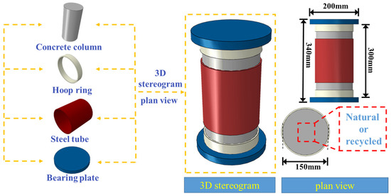
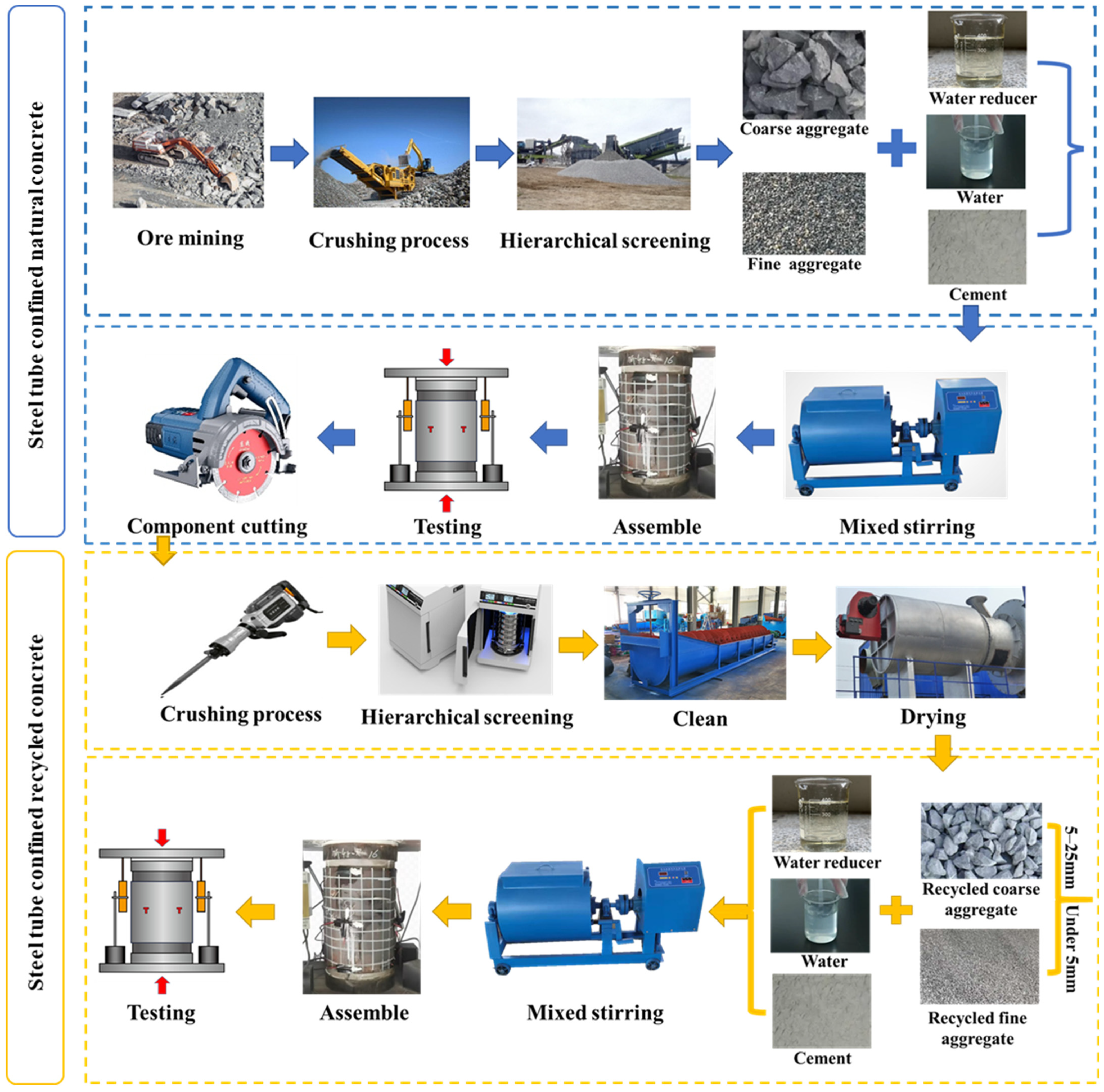
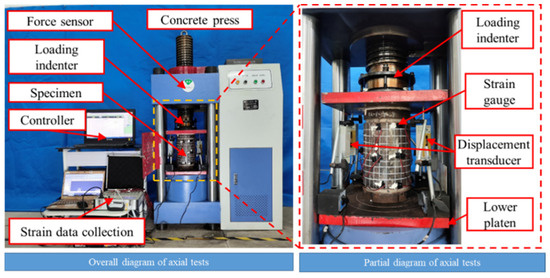
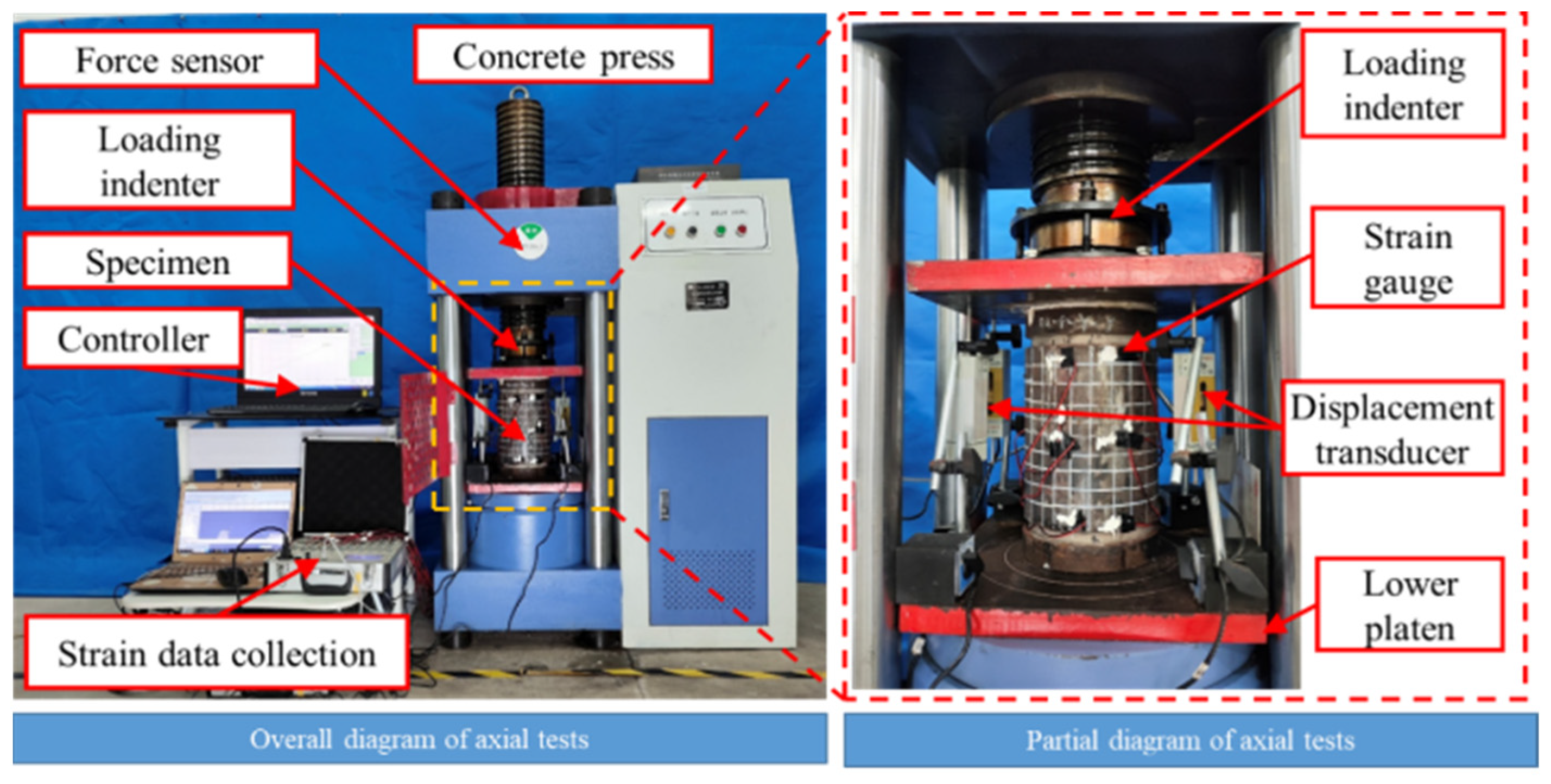
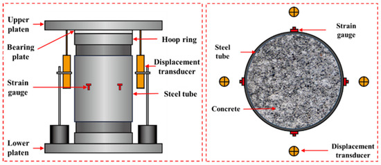
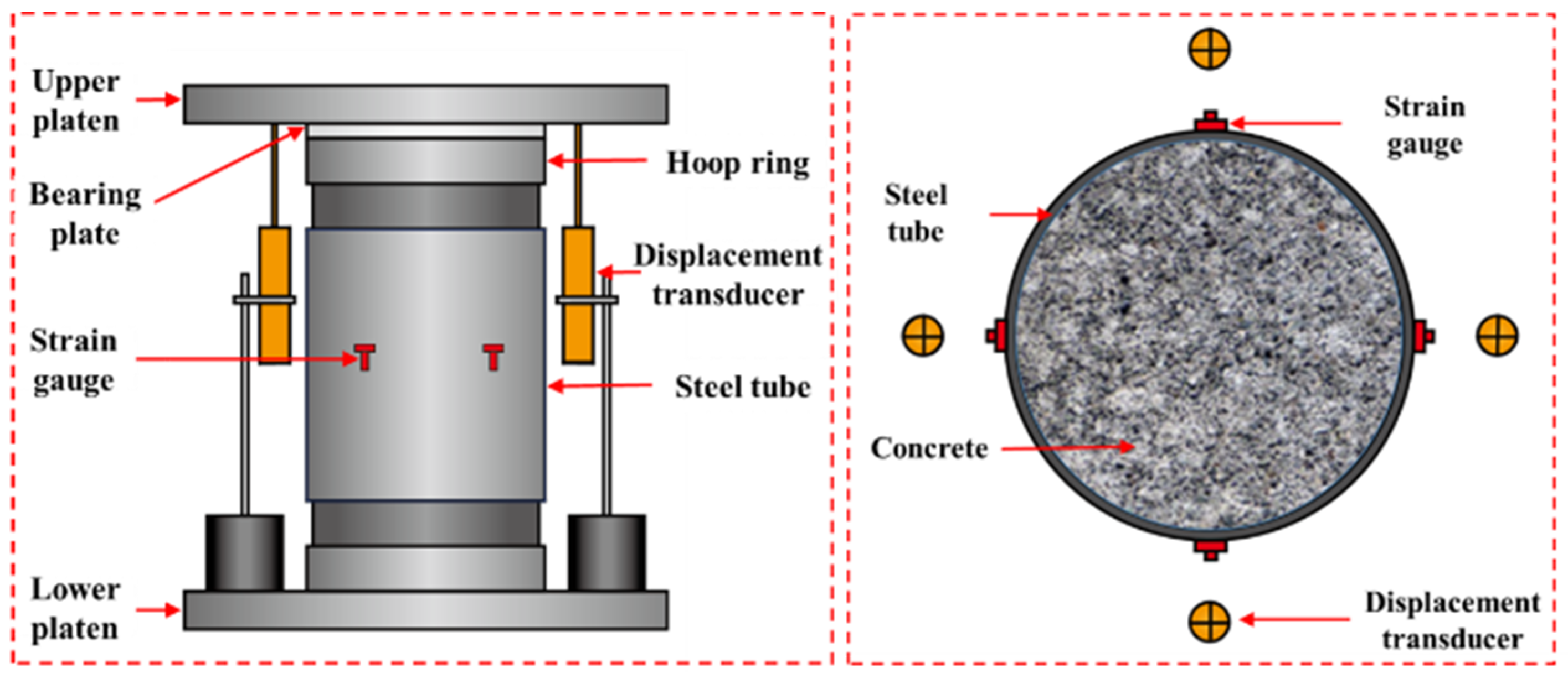
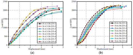
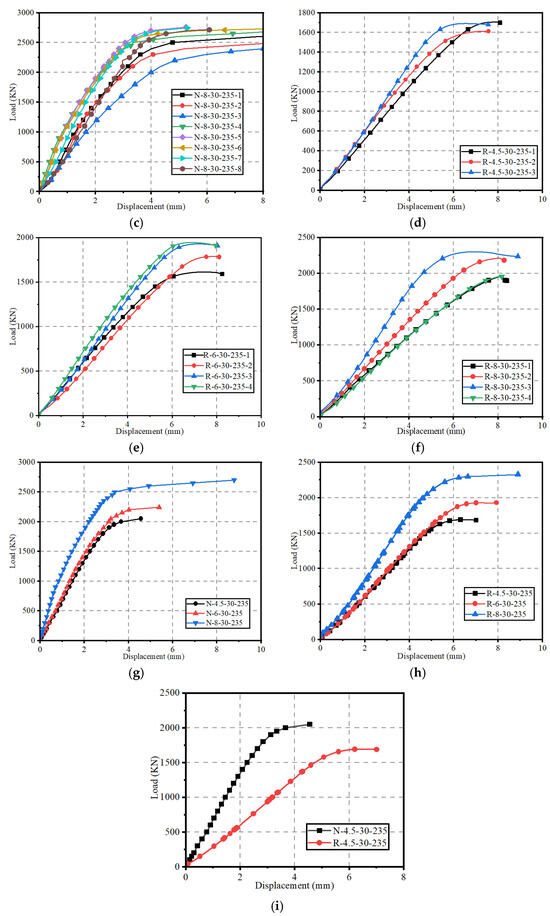
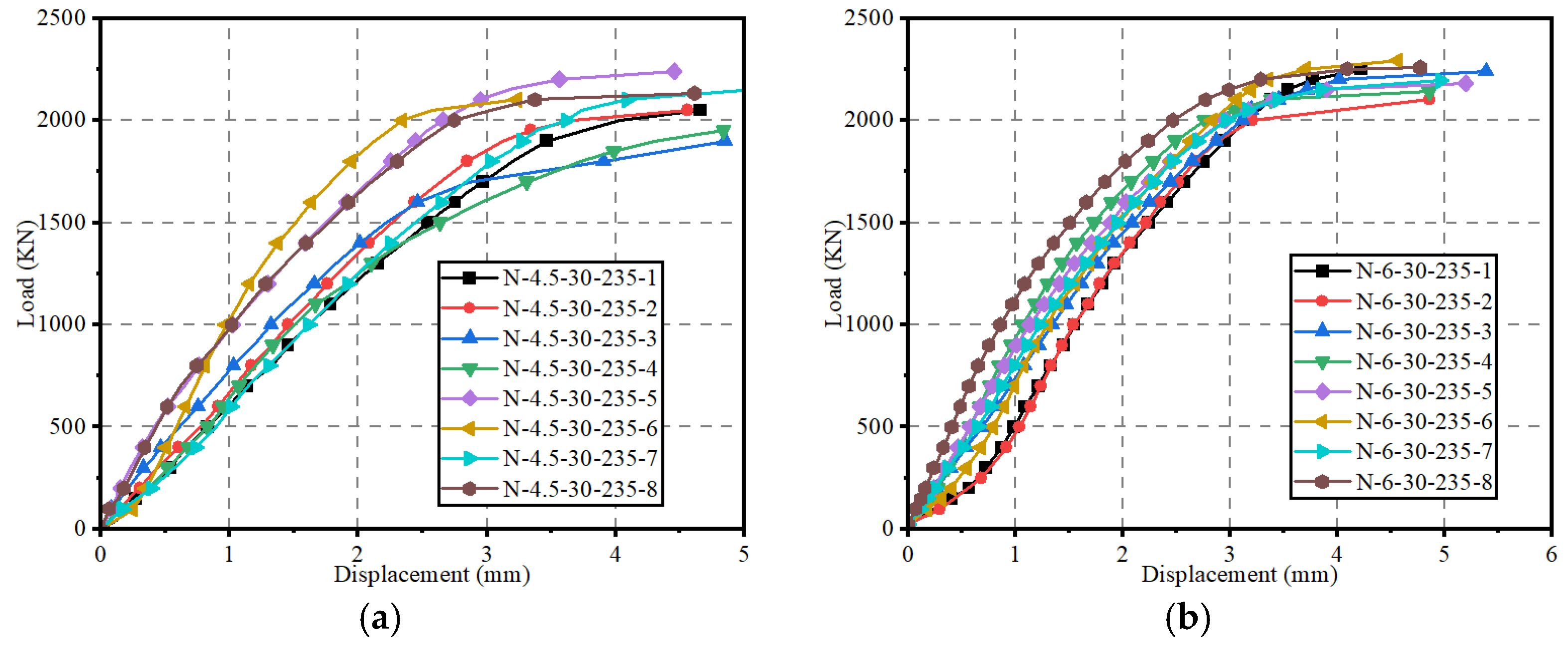
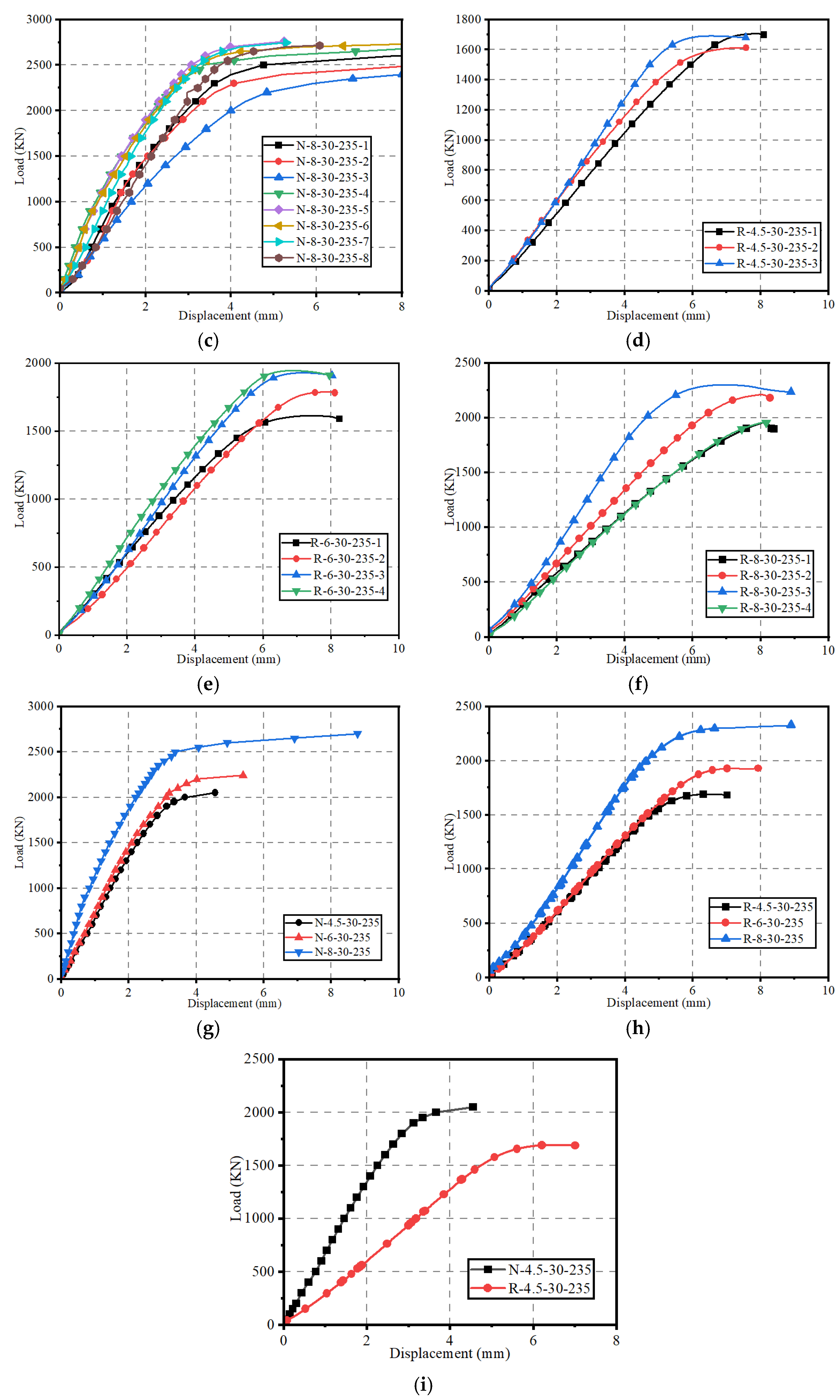
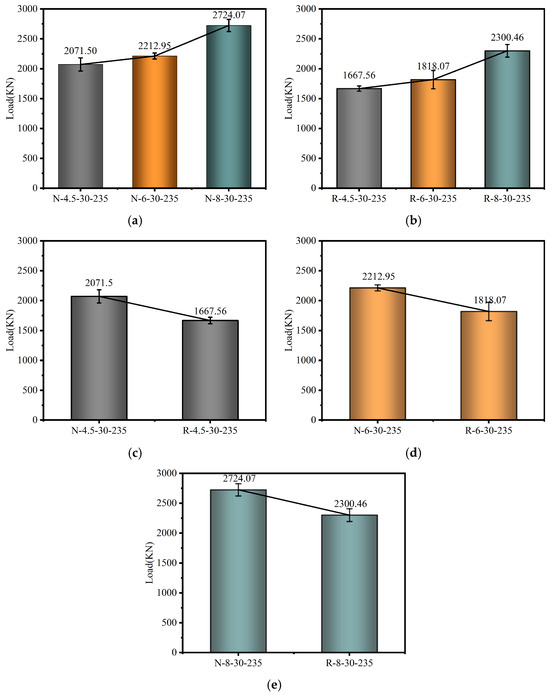
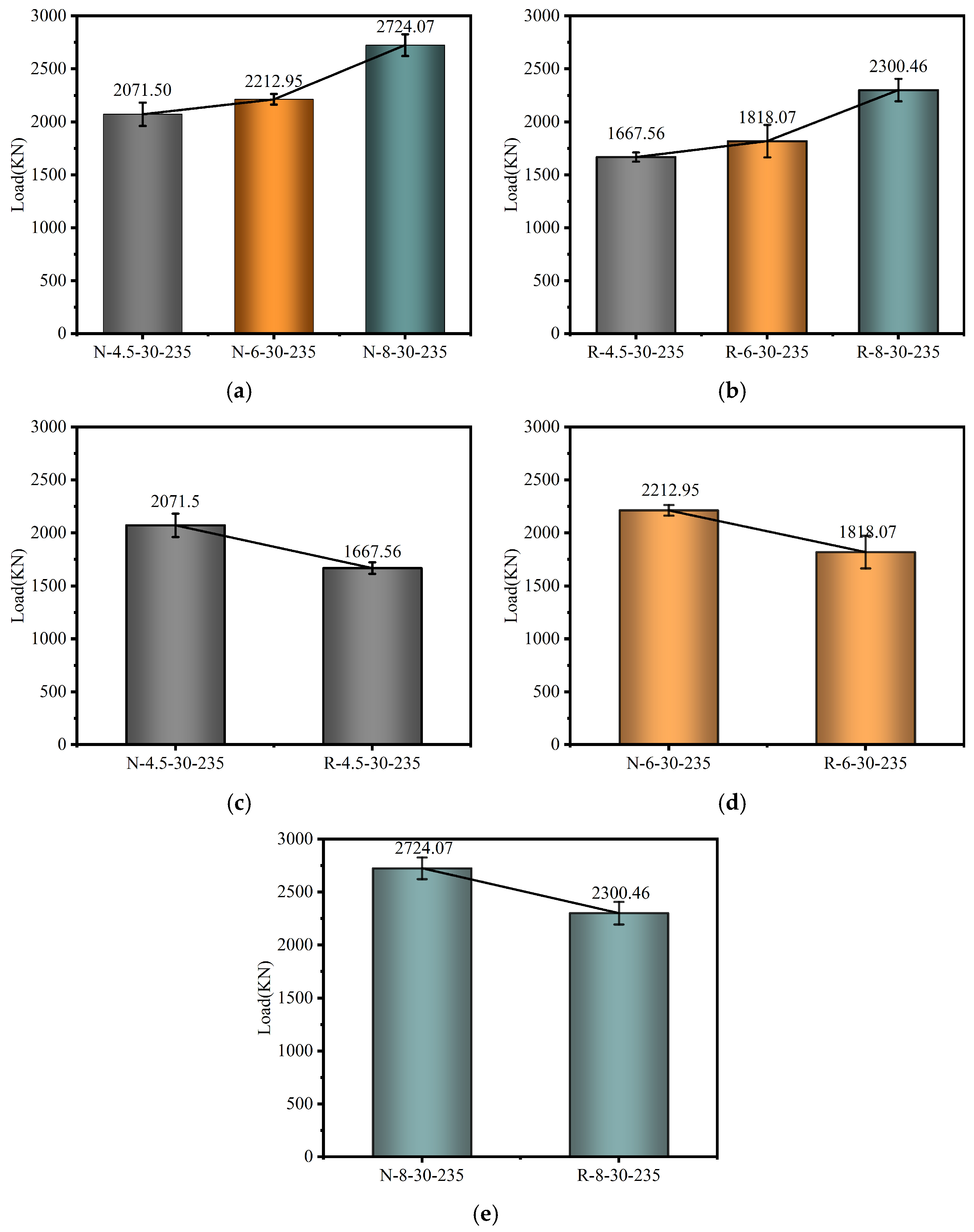
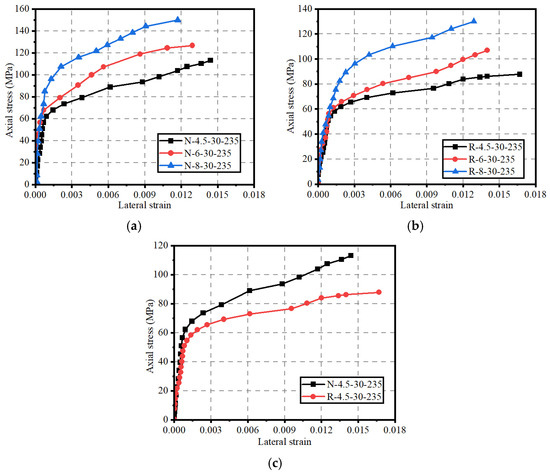
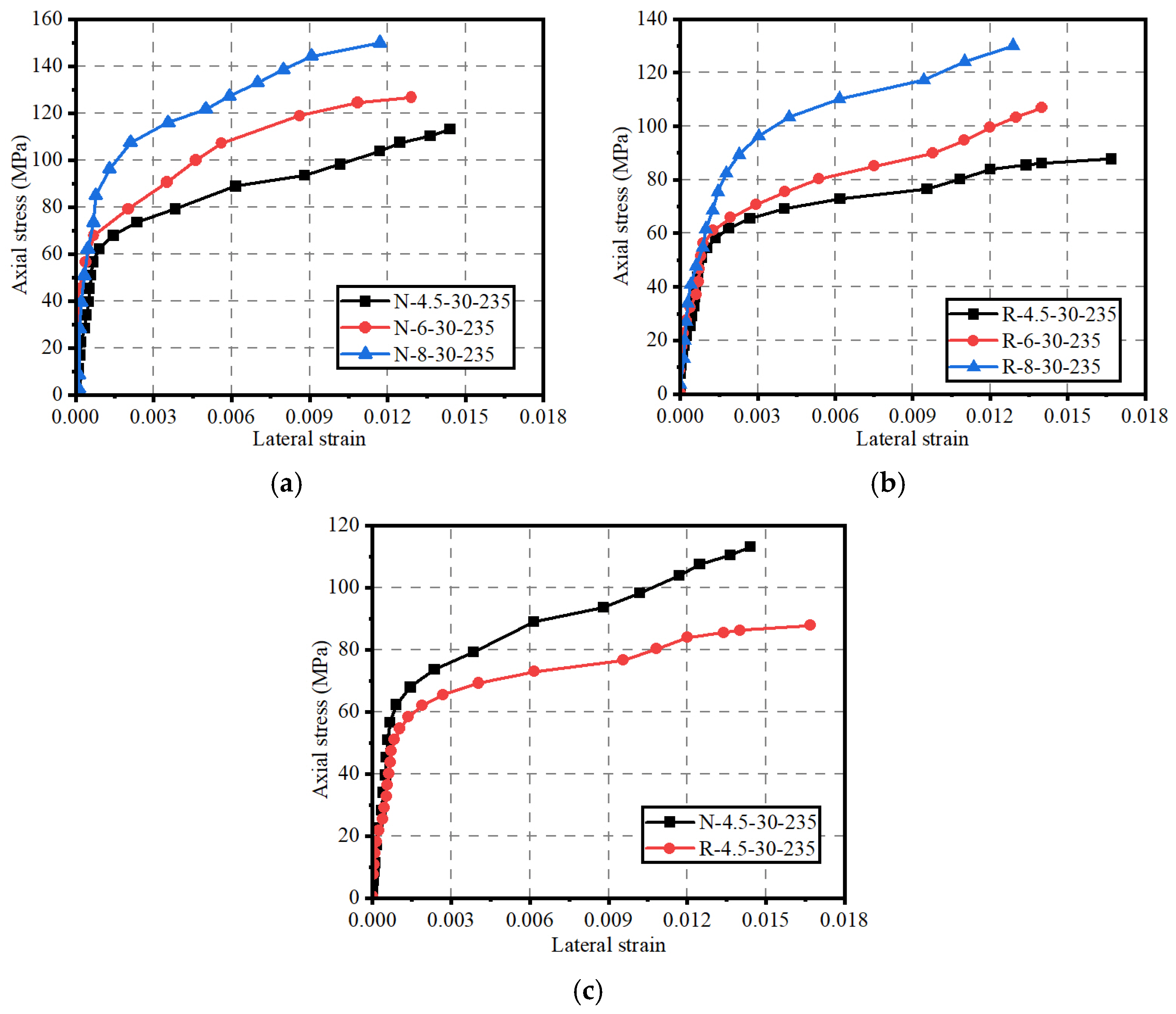
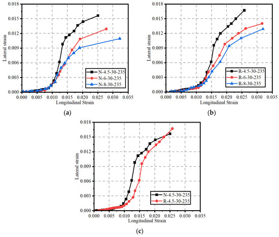
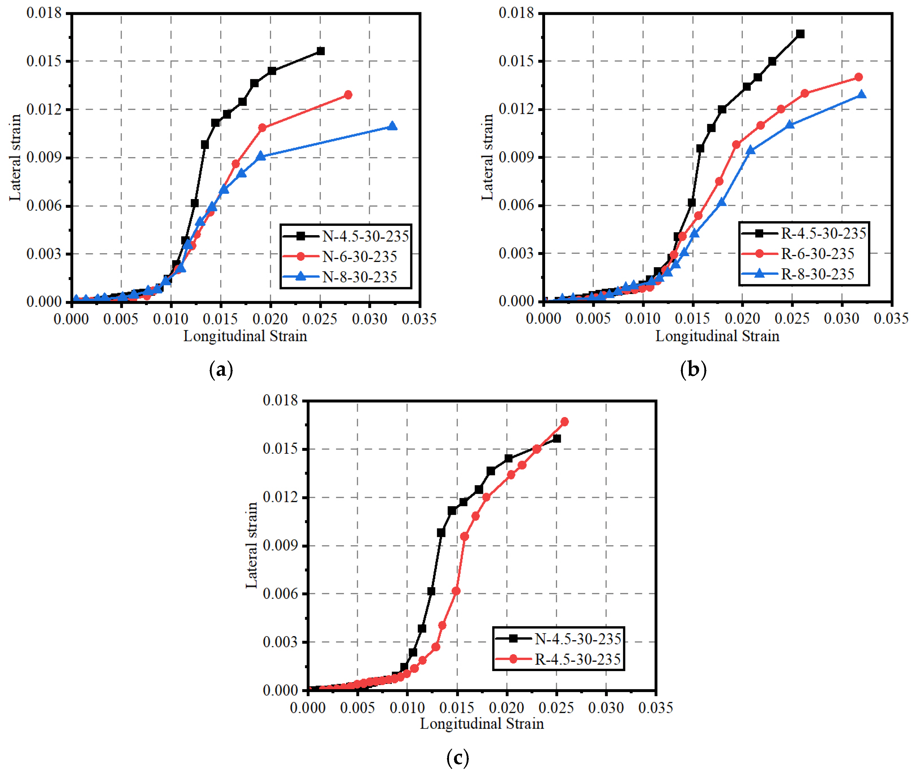
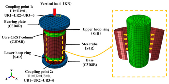
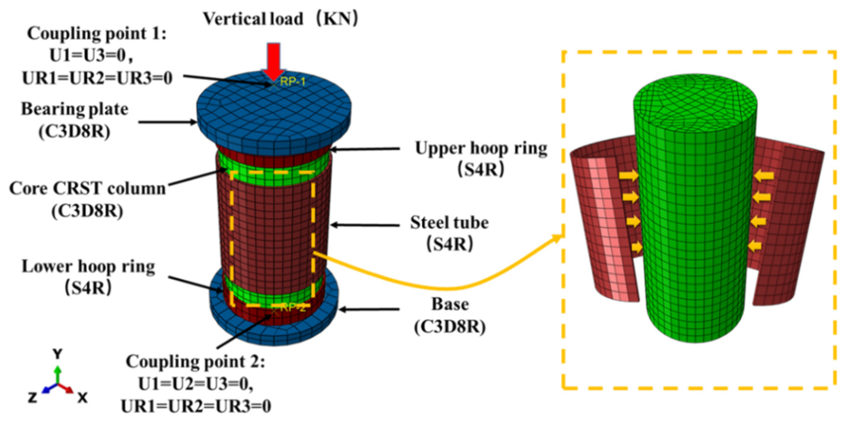
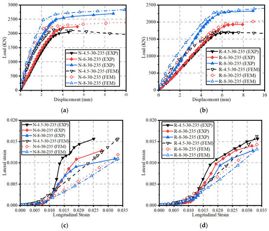
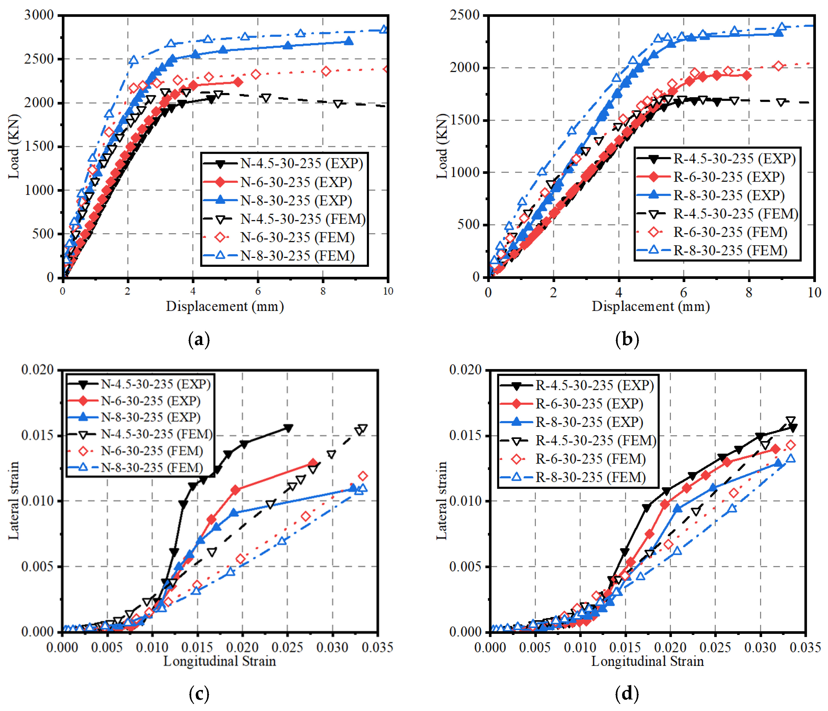
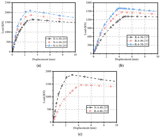
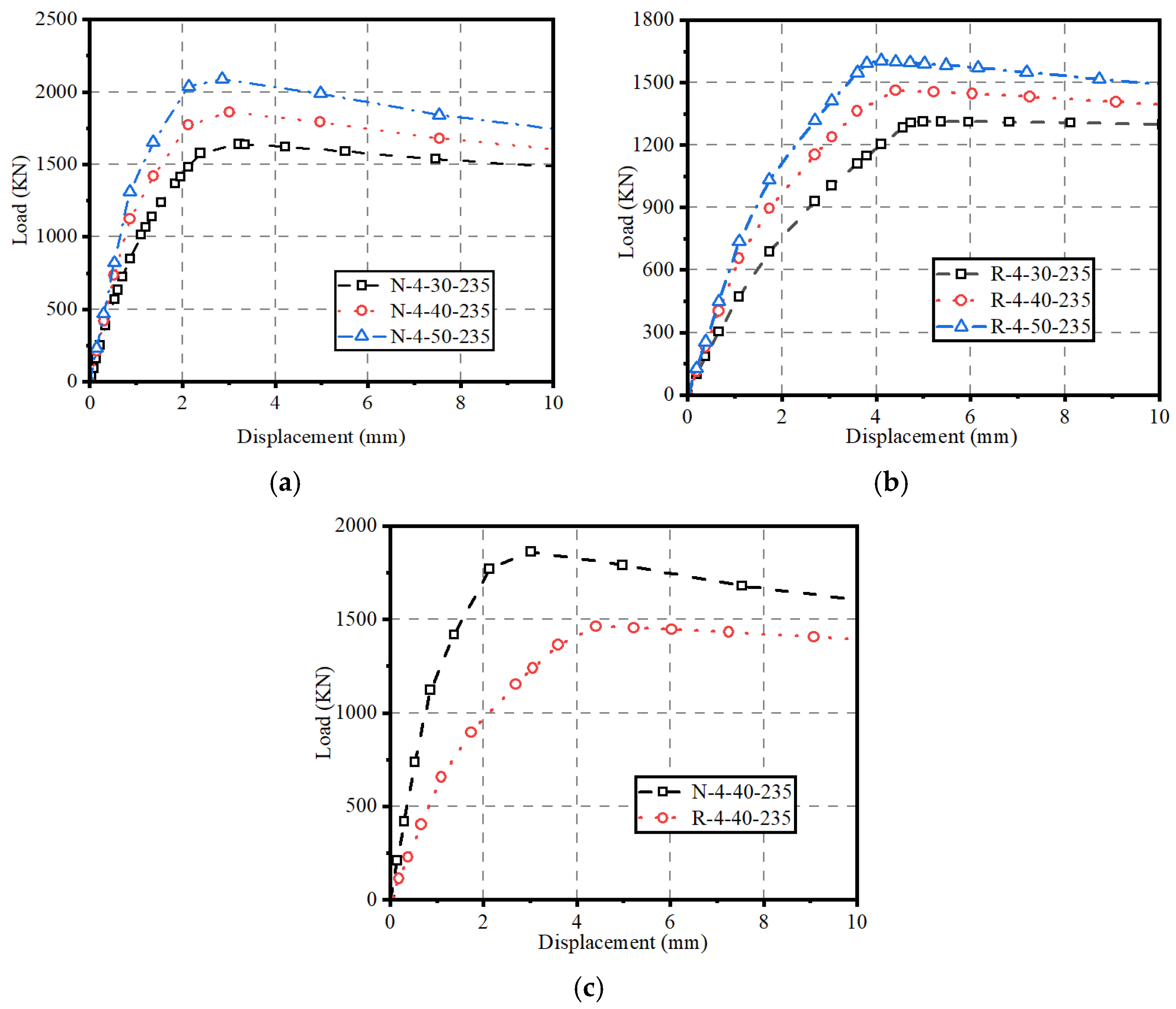
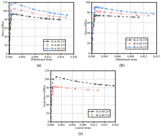
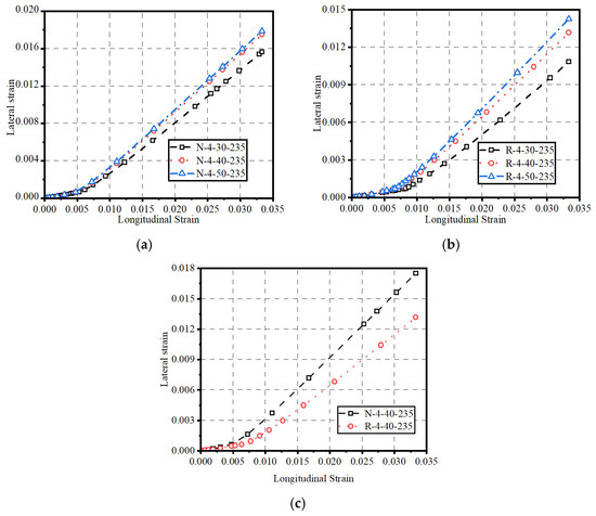
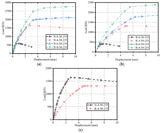
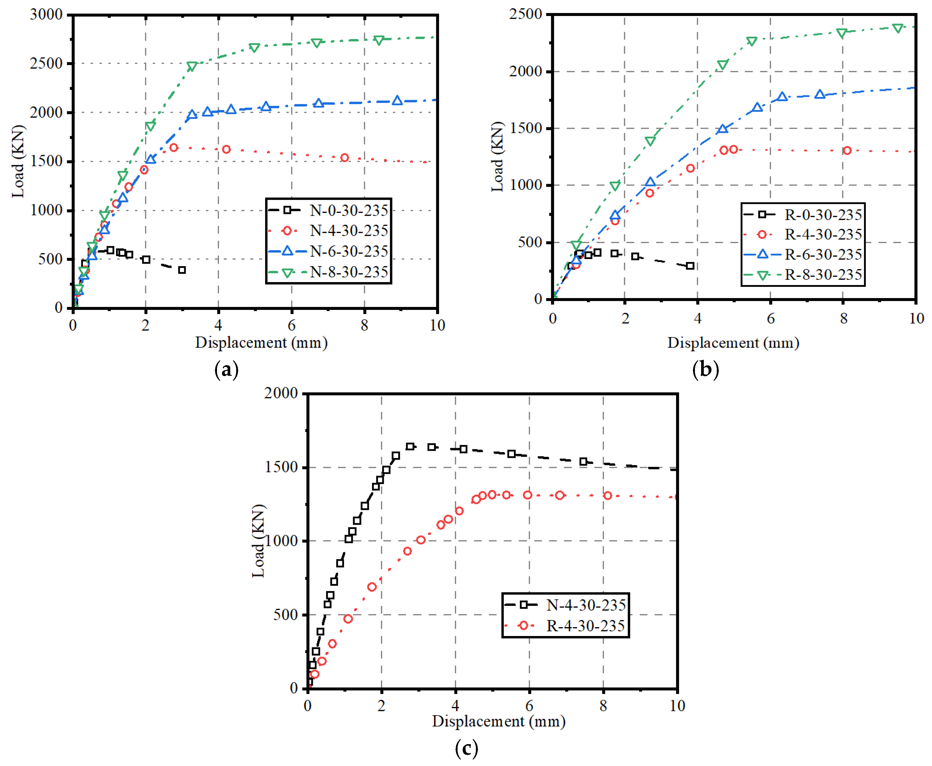
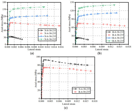
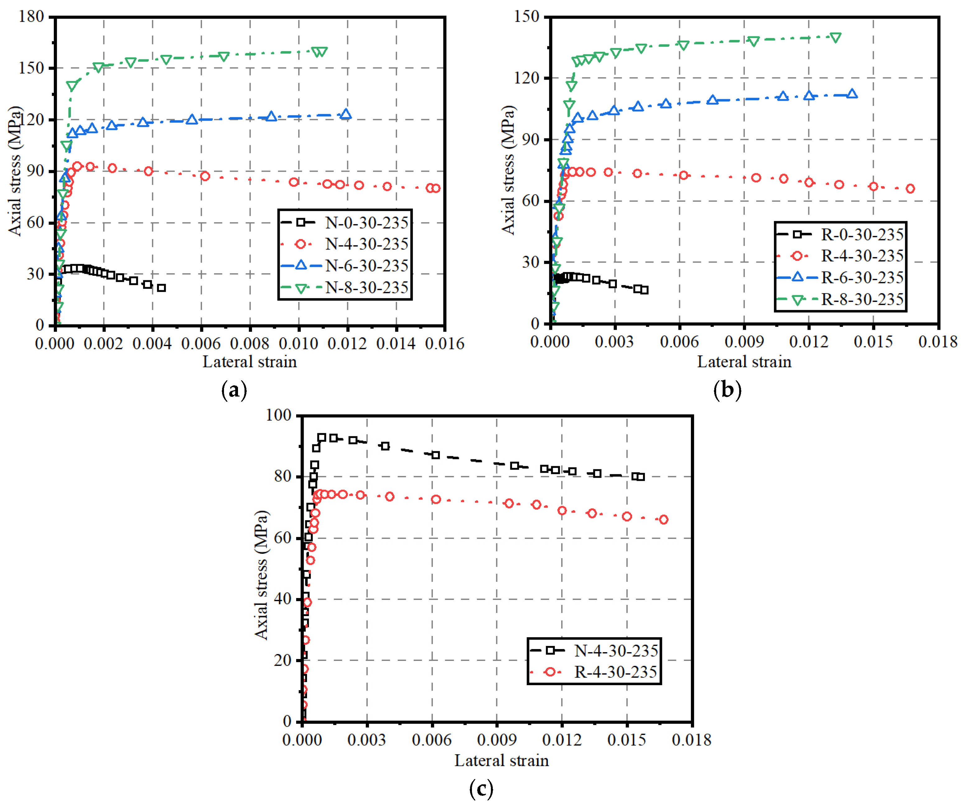
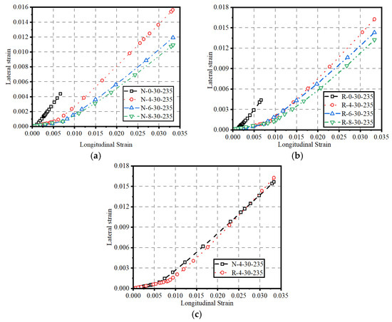
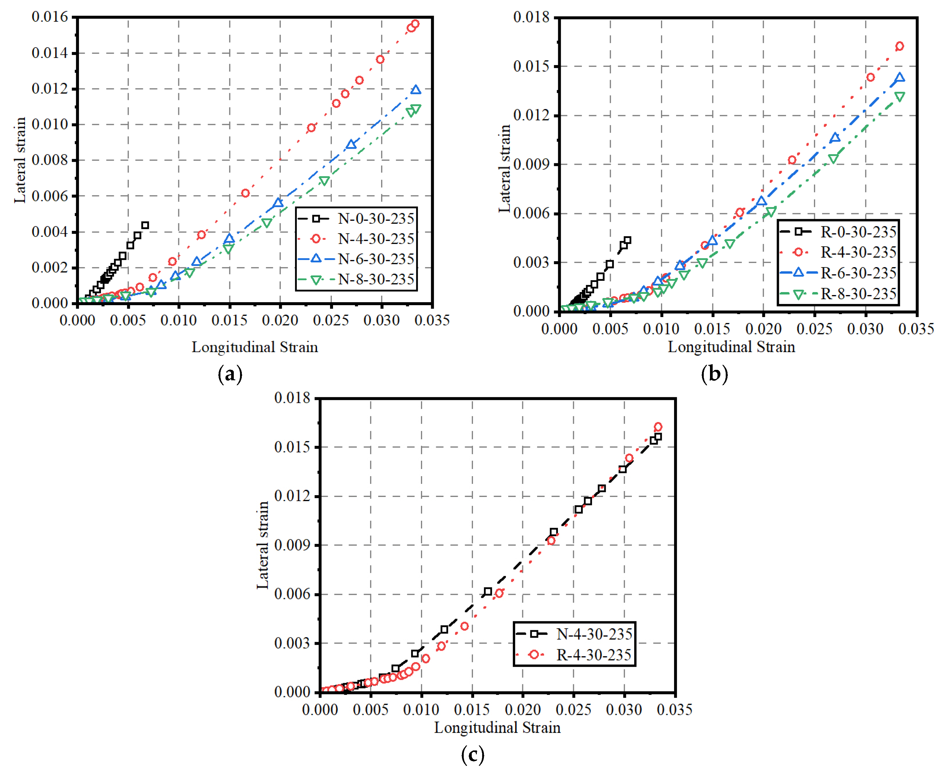
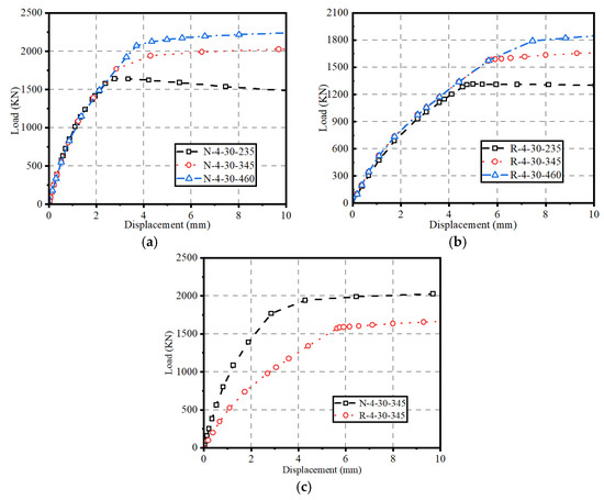
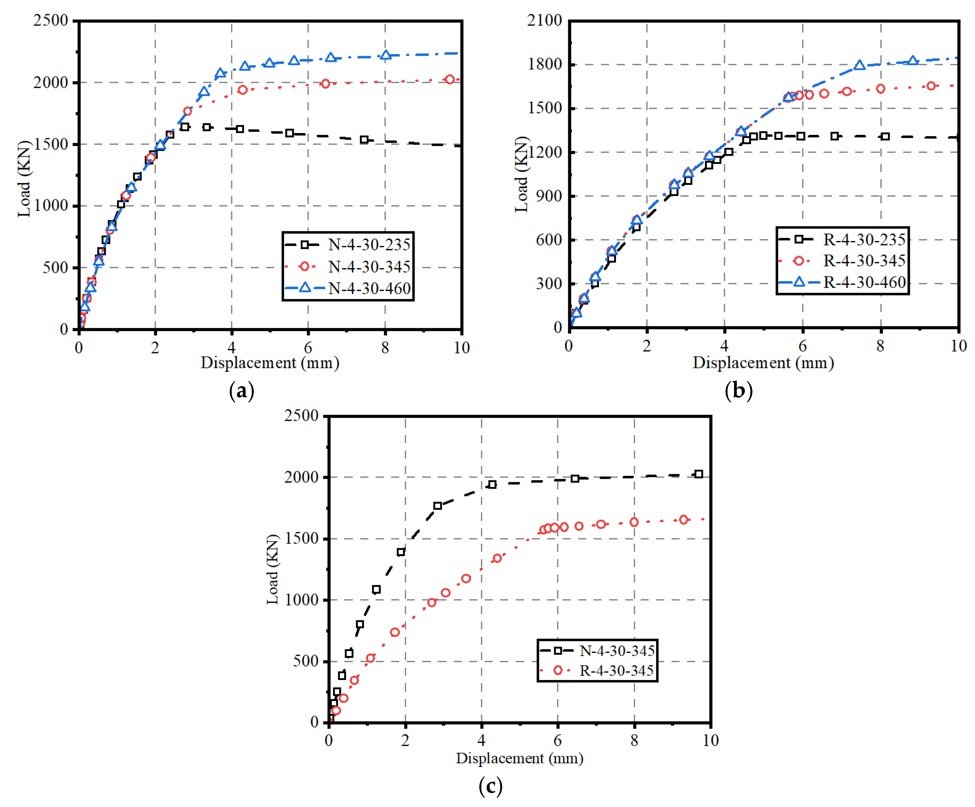
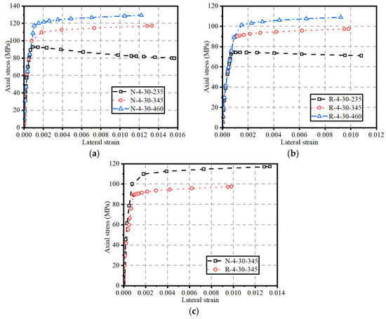
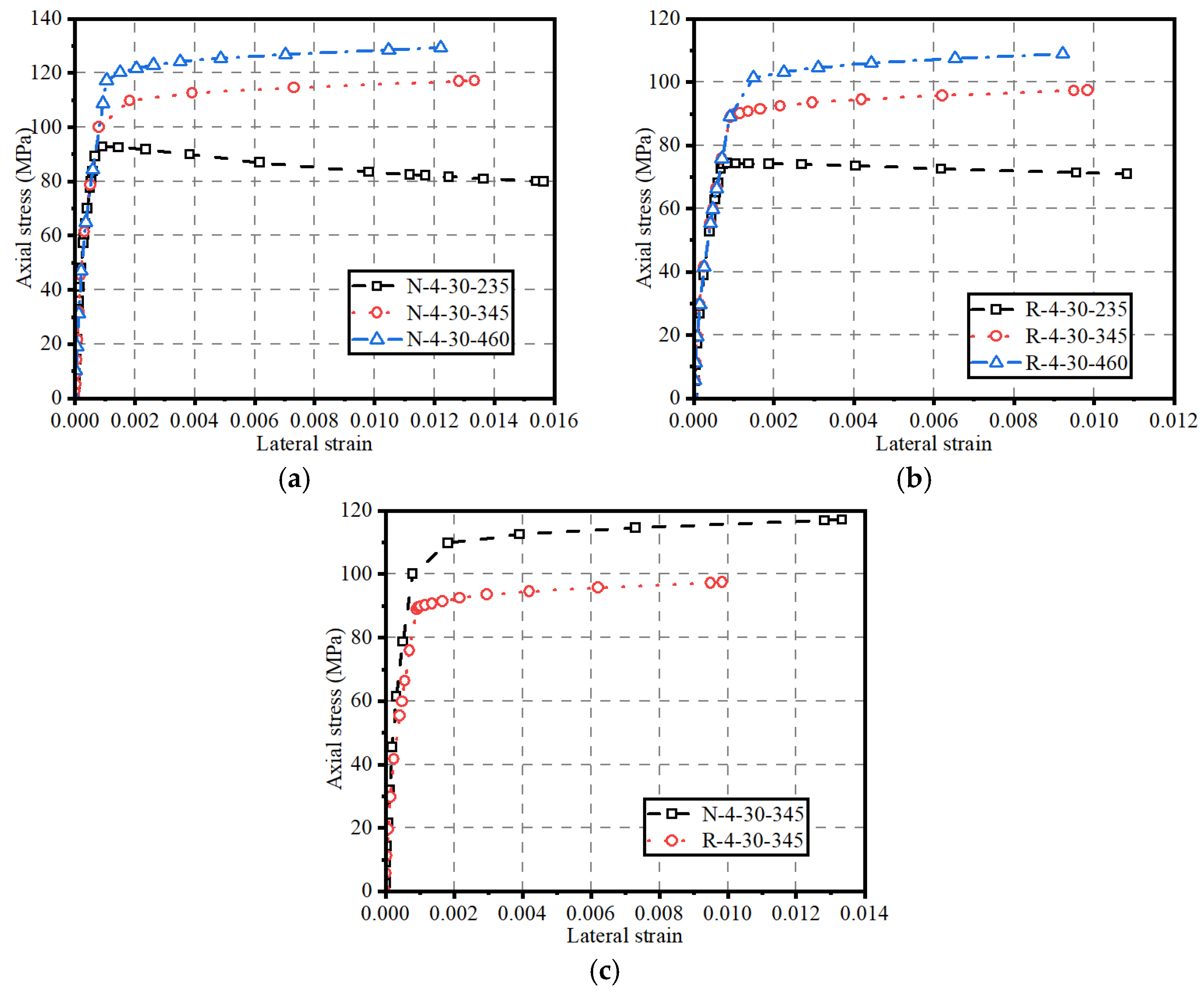
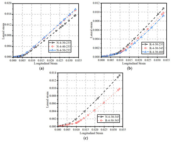
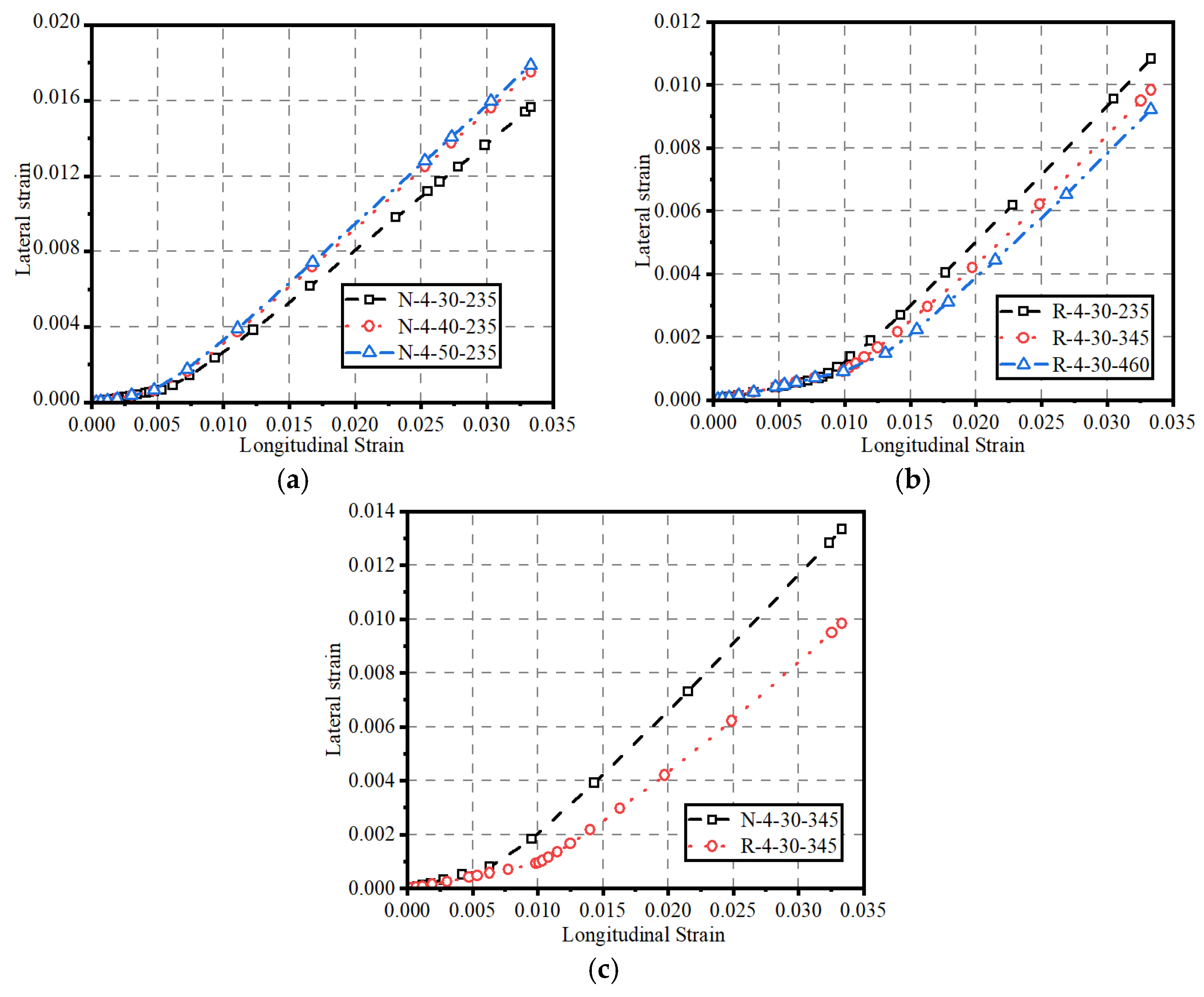
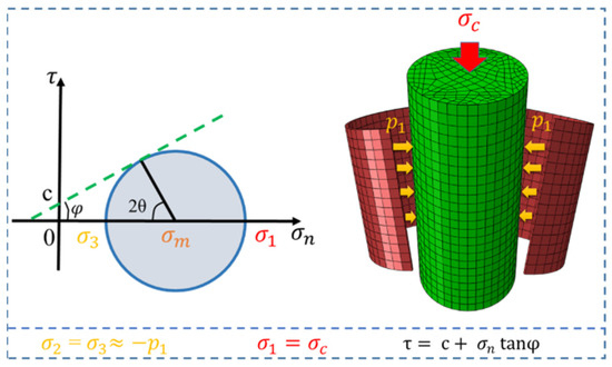
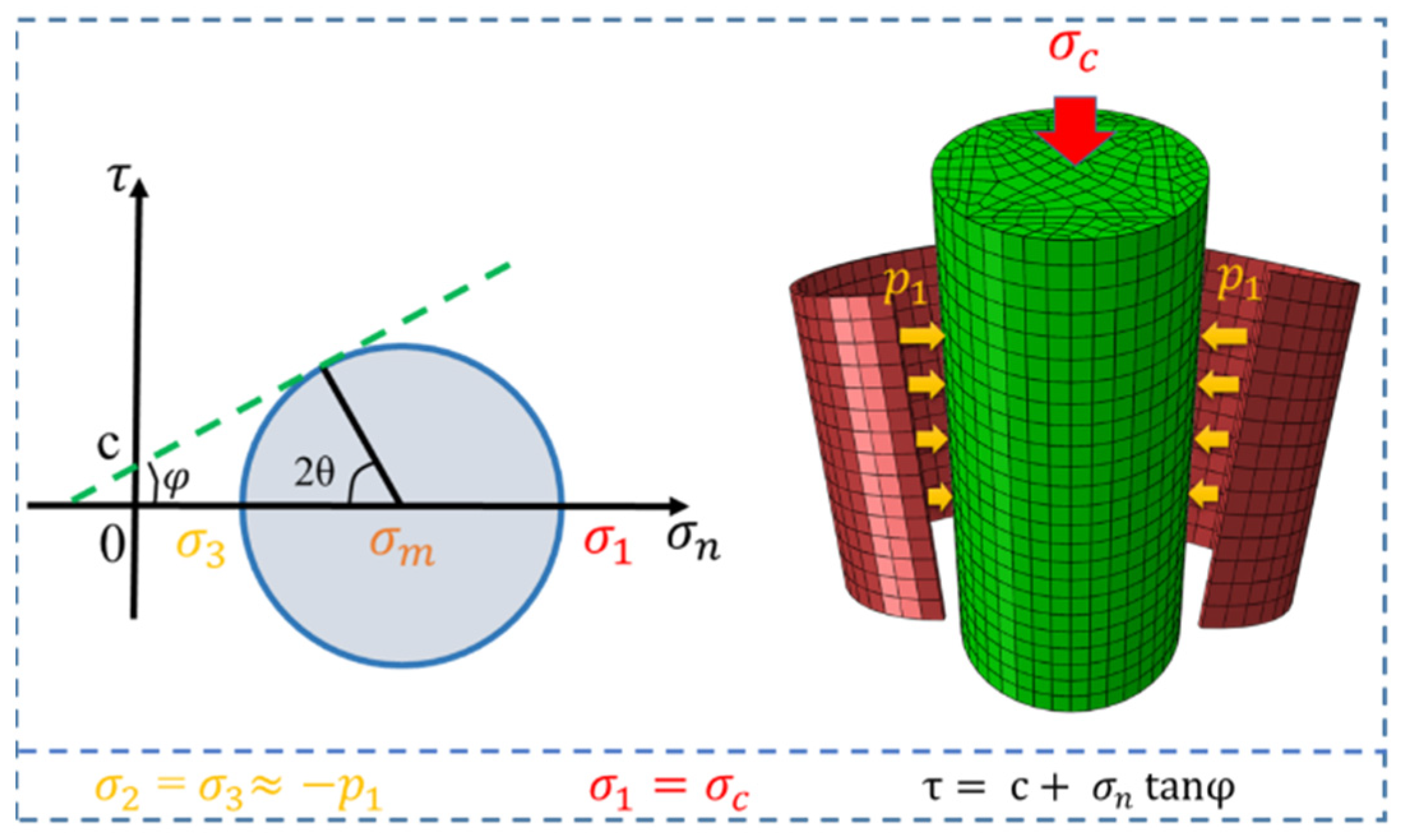
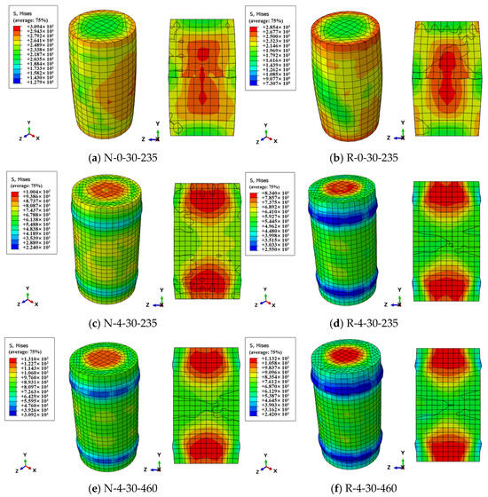
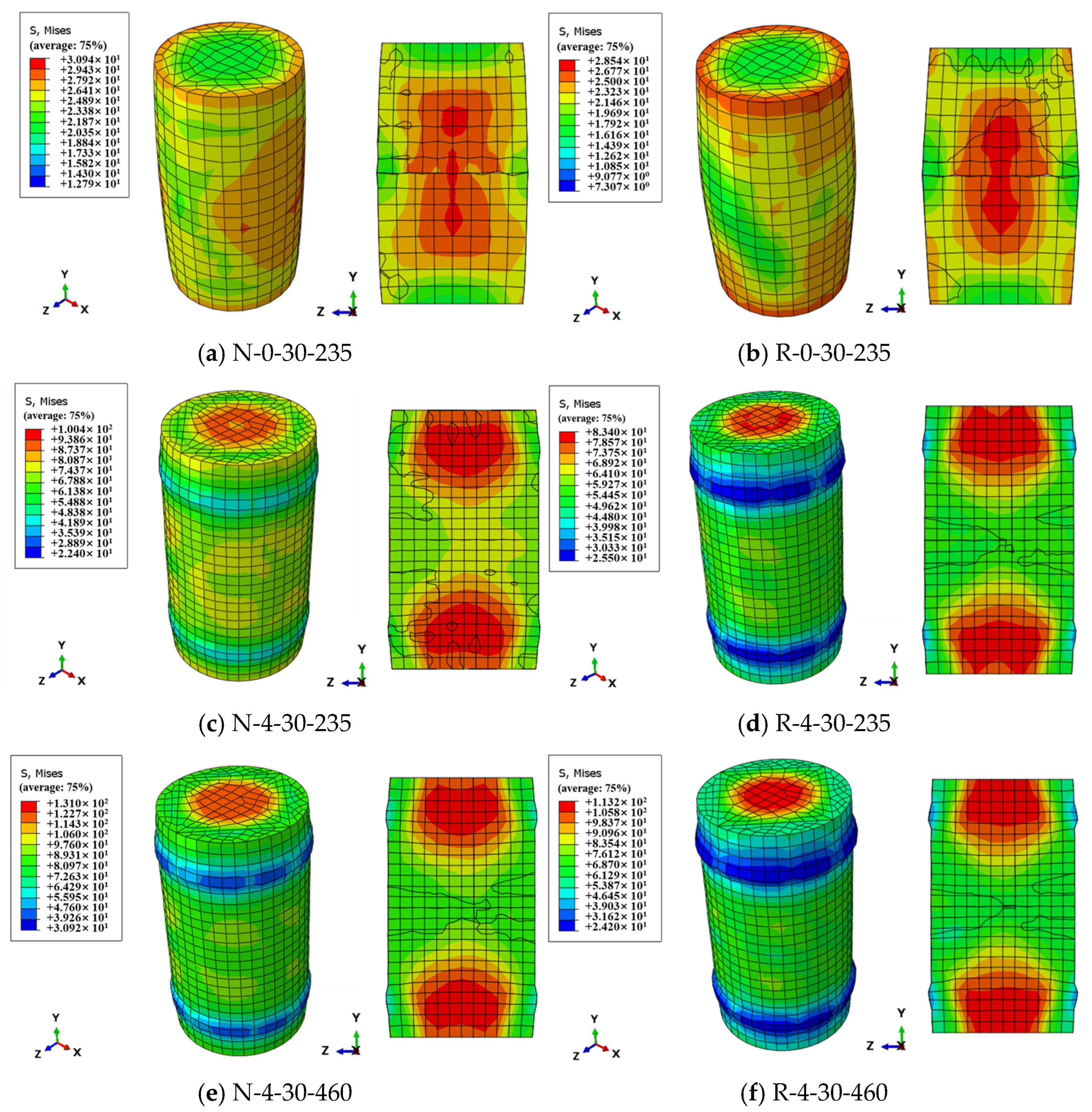
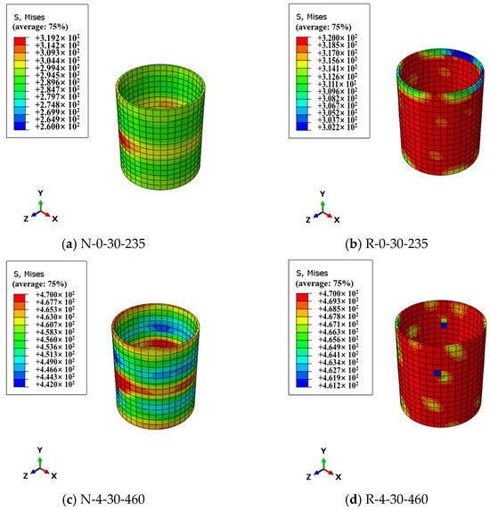
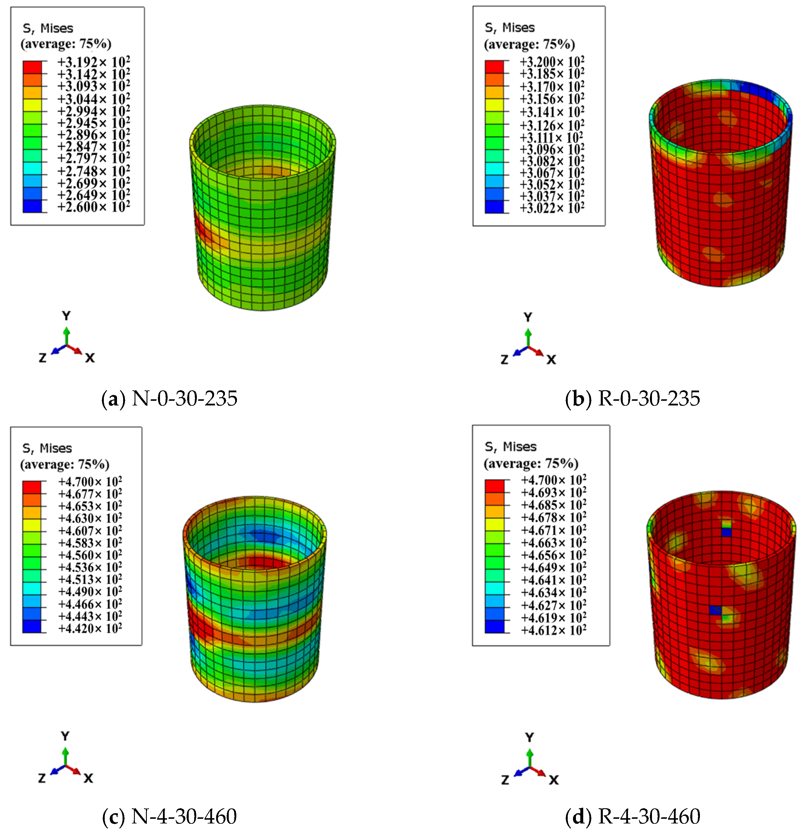
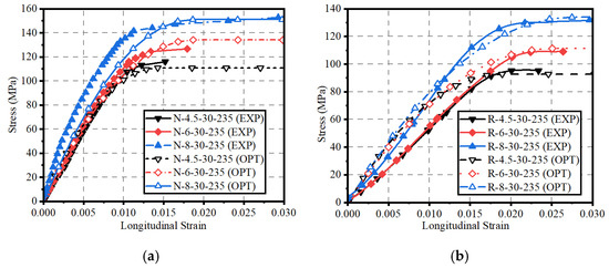
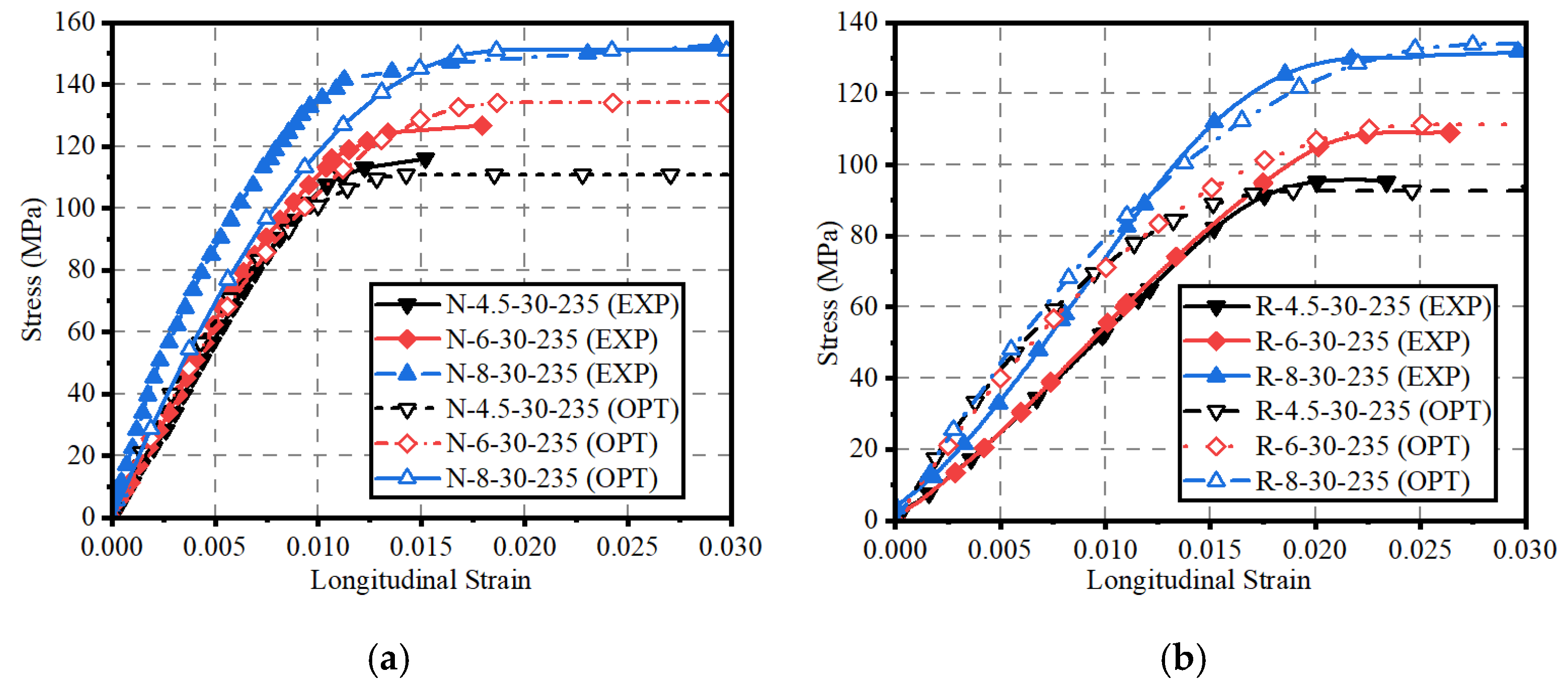

Disclaimer/Publisher’s Note: The statements, opinions and data contained in all publications are solely those of the individual author(s) and contributor(s) and not of MDPI and/or the editor(s). MDPI and/or the editor(s) disclaim responsibility for any injury to people or property resulting from any ideas, methods, instructions or products referred to in the content. |
© 2026 by the authors. Licensee MDPI, Basel, Switzerland. This article is an open access article distributed under the terms and conditions of the Creative Commons Attribution (CC BY) license.