


Abstract
The connection between the space frame and its supporting columns is a critical aspect of structural design. The way these two elements are joined significantly influences the overall stability, load transfer, and behavior of the entire structure. This study investigates the seismic behavior of composite double-layer space frames with reinforced concrete (RC) slabs under three alternative support configurations: simple point supports, inverted-pyramid supports, and crosshead-beam supports. A detailed finite element (FE) model was developed in ABAQUS to conduct a nonlinear time-history analysis under recorded earthquake excitation. The selected record captures the temporal variation in ground motion and enables an accurate assessment of structural response under dynamic loading. The Concrete Damage Plasticity model was incorporated into the analysis of the concrete slab. The steel was modeled using an elastic–plastic material behavior to mimic the formation of plastic hinges. Maximum lateral displacements, base shear forces, and hysteretic behavior were studied to evaluate the comparative performance of the systems. The results show that the inverted-pyramid configuration reduced vertical (Y-direction) displacement by 33.6% compared to the simple point support. At the same time, the crosshead-beam system exhibited similar levels of vertical displacement. However, it exhibited significantly enhanced energy-dissipation capacity, with hysteretic force ranges up to 1250 kN, compared to approximately 922 kN and 860 kN for the simple point and inverted configurations, respectively. In the X-direction (lateral displacement), the simple support and inverted-pyramid cases showed comparable responses, whereas the crosshead-beam configuration exhibited greater displacement, indicating reduced lateral stiffness. Overall, the results of this study indicate that the inverted-pyramid system improves displacement control, and the crosshead-beam configuration provides superior hysteretic energy dissipation. These findings highlight the importance of selecting appropriate support configurations in the seismic design of composite space frame systems.
1. Introduction
Double-layer space frames are widely recognized as among the most efficient structural systems for covering large-span buildings, including airports, exhibition halls, industrial facilities, sports arenas, and transportation terminals. Their widespread use is attributed to their high stiffness-to-weight ratio, three-dimensional load-transfer capability, structural redundancy, and architectural flexibility. Compared with conventional planar framing systems, space frames provide more efficient load distribution and reduced self-weight, making them particularly suitable for structures requiring large unobstructed spaces and enhanced structural stability under complex loading conditions [1].
The structural behavior of space frame systems under earthquake excitation is more complex than that of ordinary framed structures due to the interaction among geometric configuration, multidirectional force transfer, connection behavior, and support conditions. Since seismic forces are redistributed through multiple load paths, even minor changes in the boundary configuration may significantly affect stiffness, vibration characteristics, internal force redistribution, and energy-dissipation capacity. Consequently, the connection system between the space frame and its supporting columns is a critical component that significantly influences the structure’s seismic performance.
Previous studies have shown that the method used to transfer forces between the space frame and supporting columns plays a decisive role in the overall structural response. According to Lan [1], space frame support systems may include direct point support, inverted-pyramid support, and crosshead-beam support, each providing distinct mechanisms of load transfer and stiffness distribution. The supporting configuration influences force concentration near column regions, structural rigidity, and the redistribution of seismic actions throughout the spatial system. Furthermore, support detailing significantly affects the transfer of concentrated reactions from the space frame to the columns, especially in long-span structures where excessive member forces may develop near support regions [1]. Therefore, selecting an appropriate support arrangement is particularly important for a structure subject to seismic loading.
The fundamental concepts related to the analysis and design of space structures were initially established by the International Association for Shell and Spatial Structures (IASS), which emphasized the importance of geometric stability and joint configuration in spatial steel systems [2]. Later investigations by Ramaswamy et al. [3] and Rizwan and Bhatti [4] examined the structural performance and behavioral characteristics of double-layer square-on-square grids. They highlighted the influence of geometric configuration on force distribution and structural response in spatial systems. Karamanos and Karamanos [5] investigated the seismic design behavior of double-layer space grids. They demonstrated that support configurations and boundary conditions significantly influence force redistribution and structural stiffness in spatial steel systems. Their study emphasized that inadequate support detailing may increase stress concentrations near support regions, thereby affecting the overall seismic response and structural stability of space frame structures.
With advances in computational methods and nonlinear finite element analysis, increasing attention has been directed toward evaluating the seismic behavior of spatial structures under dynamic loading.
El-Sheik [6] investigated the dynamic behavior of space trusses and demonstrated that geometric stiffness plays a significant role in controlling modal characteristics and the vibration response under dynamic loading. Moghaddam [7] discussed the seismic vulnerability of spatial systems and emphasized the importance of global stiffness and connection behavior in controlling structural instability during earthquake excitation. Experimental studies conducted by Bezerra et al. [8] also demonstrated that improvements in joint detailing can enhance load-carrying capacity. Recent advances in finite element modeling have improved the ability to simulate the complex interaction between steel and concrete components in spatial structural systems. Liu et al. [9] conducted experimental and numerical investigations of steel-reinforced concrete spatial frames and showed that interactions among structural components affect stiffness, deformation behavior, and seismic response under earthquake loading. Their observations also indicated that structural configuration influences force redistribution and displacement demand in spatial systems. Nie et al. [10] combined shaking-table tests with numerical simulations to study the seismic response of lattice space structures and reported that the support configuration and connection rigidity have a noticeable effect on displacement demand and energy-dissipation behavior. In a more recent study, Karimi Ghaleh Jough and Babaei [11] used nonlinear static and time-history analyses in ABAQUS to evaluate the seismic behavior of space frame structures. They observed that spatial configuration and dynamic loading characteristics affect displacement response, base shear behavior, and structural stability.
Several researchers have also examined the contribution of reinforced concrete slabs to the global seismic behavior of composite spatial systems. Cui [12] reported that reinforced concrete slabs improve damping capacity and increase the overall stiffness of space frame systems subjected to dynamic loading. Wang et al. [13] experimentally investigated composite steel–concrete space frames and concluded that slab participation enhances seismic resistance by reducing lateral deformation and improving load redistribution mechanisms. Fang et al. [14] proposed self-centering spatial systems that improve hysteretic performance and minimize residual deformation under earthquake excitation.
In parallel with these developments, modern earthquake engineering research has increasingly focused on performance-based seismic design approaches in which structural response is evaluated in terms of displacement capacity, ductility demand, stiffness degradation, and energy dissipation, rather than solely on elastic strength requirements. Chopra [15], Priestley et al. [16], and Fardis [17] emphasized that nonlinear time-history analysis provides a more reliable representation of structural behavior under severe seismic loading, particularly for irregular and spatial structural systems. Such approaches are especially important for double-layer space frames because their highly indeterminate behavior and multidirectional load-transfer mechanisms cannot be adequately represented using simplified linear procedures.
More recently, advanced seismic-control and optimization techniques have been introduced for spatial structures. Taymus et al. [18] studied the seismic optimization of steel space frame buildings equipped with triple-friction pendulum isolators and reported significant improvements in displacement control. Despite these significant developments, the available literature still exhibits several limitations. Most previous investigations have focused on either bare steel space frames, isolated structural systems, or simplified support representations. Furthermore, few studies have examined the combined influence of reinforced-concrete-slab interaction and alternative support configurations on the nonlinear seismic response of double-layer space frames. In addition, comprehensive comparative studies employing identical earthquake excitation, consistent numerical modeling parameters, and detailed hysteretic evaluation remain scarce. Consequently, the effect of support conditions on stiffness degradation, lateral displacement demand, base shear response, and energy dissipation behavior of composite double-layer space frames has not yet been fully clarified.
Accordingly, the present study investigates the seismic behavior of double-layer composite space frames with reinforced-concrete slabs under three alternative support configurations: simple point supports, inverted-pyramid supports, and crosshead-beam supports. Detailed three-dimensional finite element models were developed in ABAQUS, and nonlinear time-history analyses were performed under earthquake excitation. The reinforced concrete slab was modeled using the Concrete Damage Plasticity (CDP) approach to simulate nonlinear concrete behavior under cyclic loading conditions accurately. Structural response was evaluated in terms of maximum lateral displacement, base shear capacity, and hysteretic behavior to provide a comprehensive assessment of stiffness, strength, and energy-dissipation characteristics. The novelty of this study lies in the integrated evaluation of support-condition effects on composite double-layer space frames using consistent nonlinear seismic simulations and identical loading conditions. Unlike previous investigations that primarily focused on isolated structural aspects, the present work systematically examines the interaction among support configuration, slab stiffness contribution, and nonlinear dynamic response within a unified analytical framework. The findings are expected to contribute to improving the seismic design and performance assessment of long-span composite spatial structures subjected to earthquake loading.
2. Analytical Background
Therefore, the analytical background presented here establishes the foundation for the modeling approach used in this research. By accounting for interactions among inertia, restoring, damping, and excitation forces, the subsequent finite element simulations are based on well-established principles of structural dynamics, ensuring both theoretical rigor and practical relevance.
2.1. Fundamentals of Structural Dynamics
Understanding the dynamic behavior of spatial structures requires developing analytical models that accurately capture their responses to various dynamic loads, such as wind, explosions, earthquakes, and mechanical vibrations. Structural dynamics are governed by four principal forces: inertia force, restoring force, damping force, and external excitation force [15,19]. These forces collectively determine a structure’s ability to resist, absorb, and dissipate energy under time-dependent loading.
where M, C, and K are the mass, damping, and stiffness matrices, respectively; u(t), (t), and ü(t) denote displacement, velocity, and acceleration vectors; and F(t) represents the external dynamic load vector.
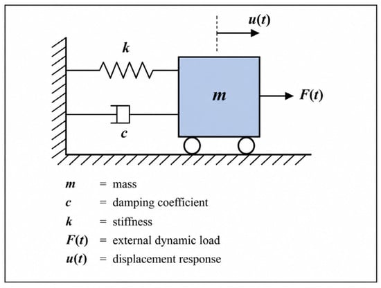
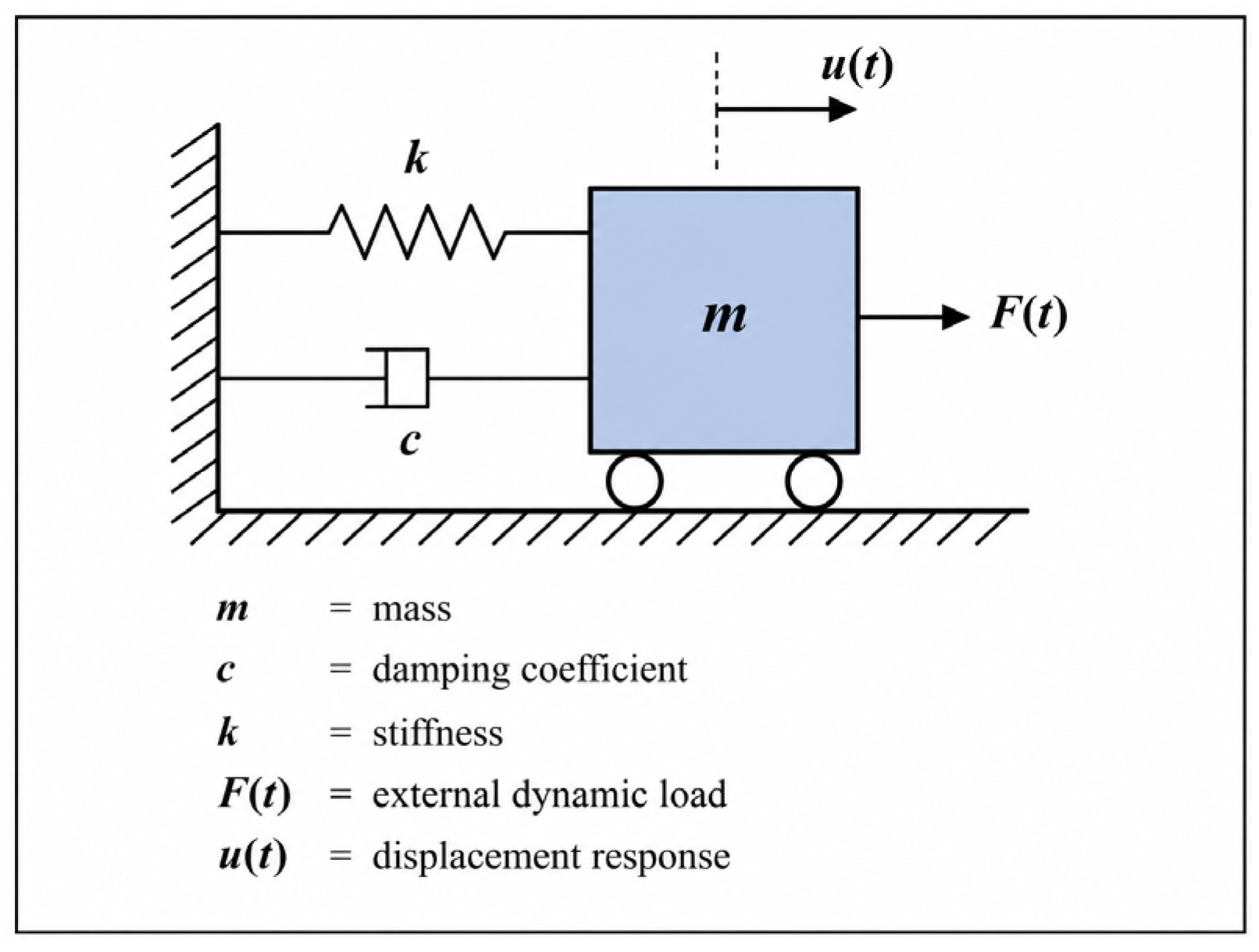
The dynamic behavior of the structural system can be conceptually represented by the idealized single-degree-of-freedom (SDOF) model shown in Figure 1, in which the mass, stiffness, damping, and external excitation components are explicitly identified.
Figure 1.
Idealized single-degree-of-freedom (SDOF) system used in dynamic analysis (adapted from Chopra [15]).
Inertia force indicates the resistance of mass to acceleration, while the restoring force relates to the elastic tendency of structural members to return to their equilibrium position. Damping force describes energy-loss mechanisms, such as material hysteresis, joint friction, and cracking, which are crucial for controlling excessive vibrations. External excitation, on the other hand, refers to the applied dynamic load, whether from seismic ground motion, wind gusts, or mechanical machinery.
2.2. Dynamic Analysis in Seismic Applications
Static analysis can provide approximate insights into structural performance when loads are applied slowly, and inertia effects are negligible. However, earthquake loading introduces rapidly varying cyclic forces that generate significant inertia effects. Consequently, dynamic analysis is necessary to accurately evaluate displacement, acceleration, internal force redistribution, and energy dissipation [15,20,21]. The finite element method (FEM) offers a robust numerical framework for dynamic structural analysis by discretizing the structure into finite elements and nodes. The governing equation of motion is solved incrementally over time to obtain the transient structural response under prescribed seismic excitation.
2.3. Finite Element Modeling Framework
The nonlinear finite element analysis conducted in this study was performed using the ABAQUS 2020 software package. The structural system was discretized into finite elements to capture the complex nonlinear response under seismic loading conditions accurately. Concrete behavior was simulated using the Concrete Damage Plasticity (CDP) model, which can represent stiffness degradation, tensile cracking, and compressive crushing under cyclic loading. Steel reinforcement was modeled using an elastic–plastic constitutive model to capture yielding and post-yield behavior under dynamic excitation.
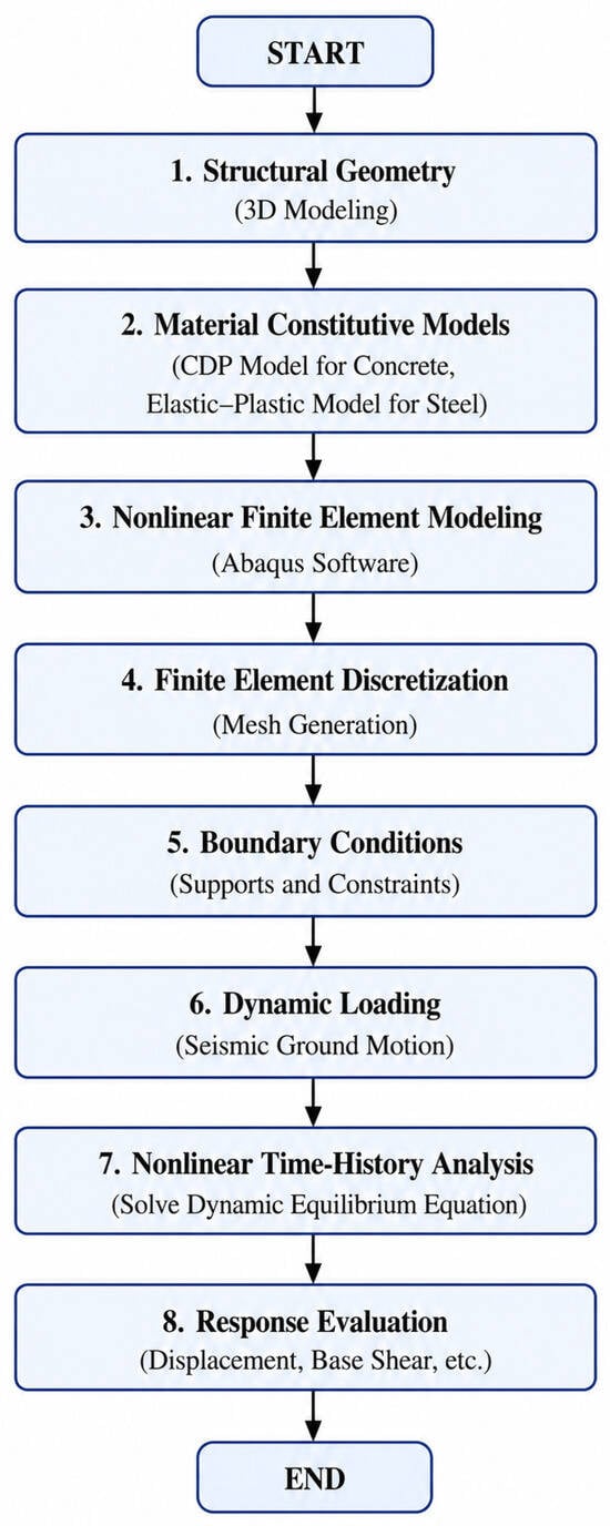
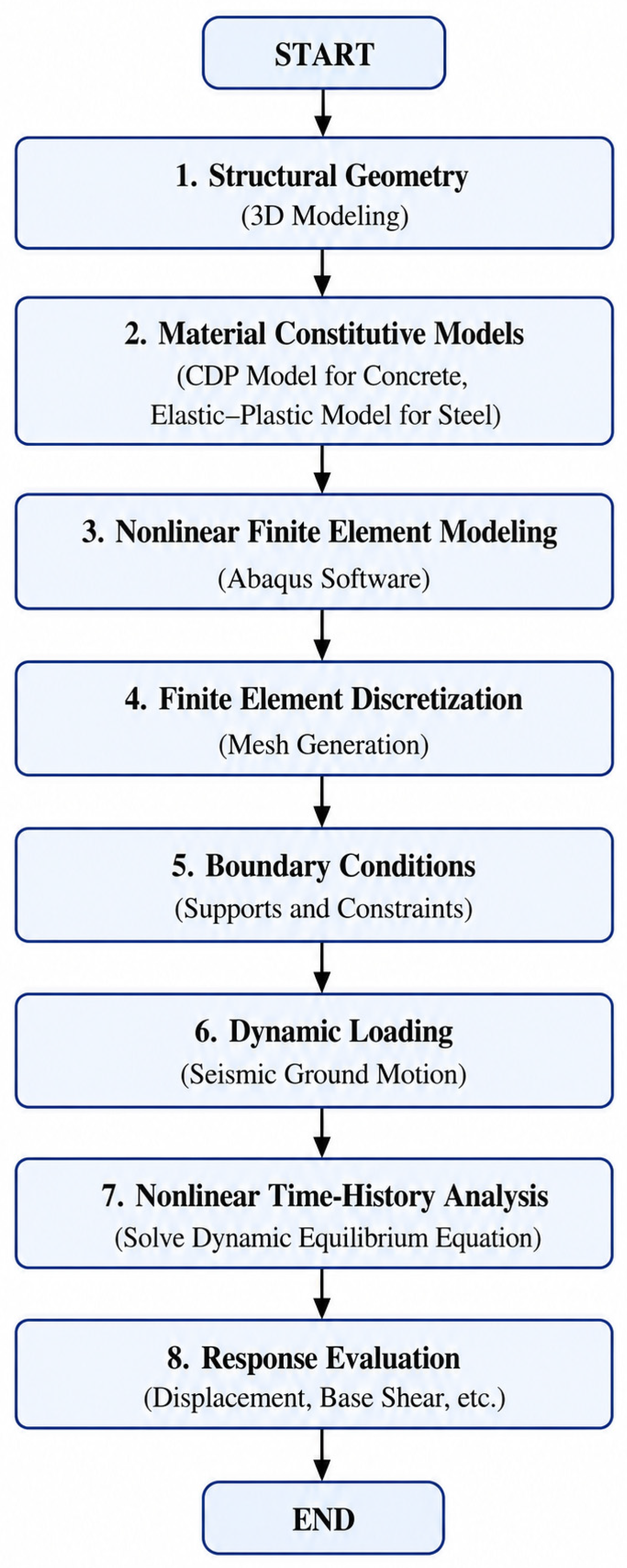
The analytical procedure adopted in this study is summarized in Figure 2. The modeling framework includes the development of structural geometry, the definition of material constitutive models, the finite element discretization, the application of boundary conditions, and the nonlinear dynamic analysis under earthquake excitation. The governing equation of motion was solved incrementally through nonlinear time-history analysis to evaluate the transient structural response.
Figure 2.
Flowchart of the nonlinear finite element analysis procedure adapted in this study.
The response parameters investigated in this research include base shear, roof displacement, acceleration response, stress distribution, energy dissipation, and overall structural damage behavior. This numerical framework ensures that the interactions among inertia, restoring, damping, and external excitation forces are accurately represented within the simulations, thereby improving both the reliability and practical relevance of the analytical results.
3. Numerical Study
To investigate the seismic performance of double-layer space frames with reinforced concrete slabs, a detailed finite element model was developed in ABAQUS, commercial software widely recognized for its accuracy in nonlinear and dynamic structural analysis. The choice of ABAQUS was driven by its capability to handle complex geometries, its extensive element library, and its established use in simulating structural responses under earthquake excitation [22].
3.1. Structural Configuration
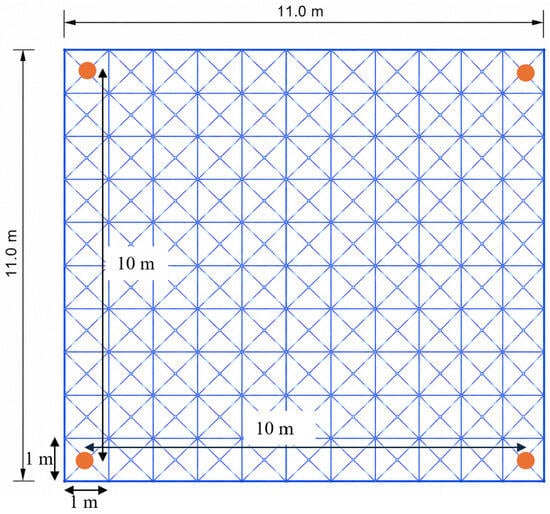
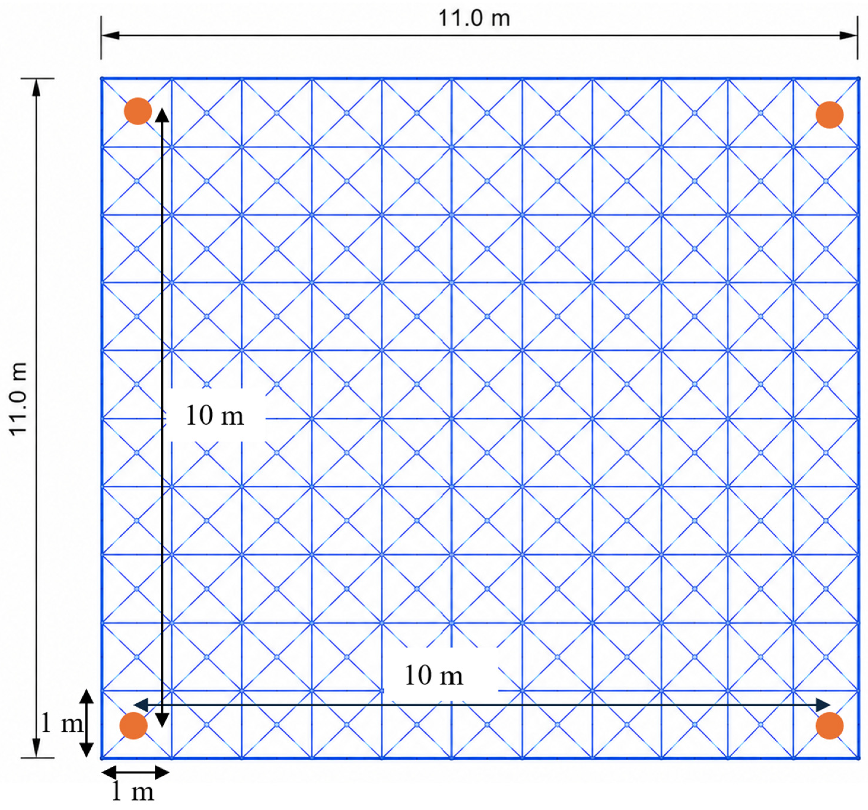
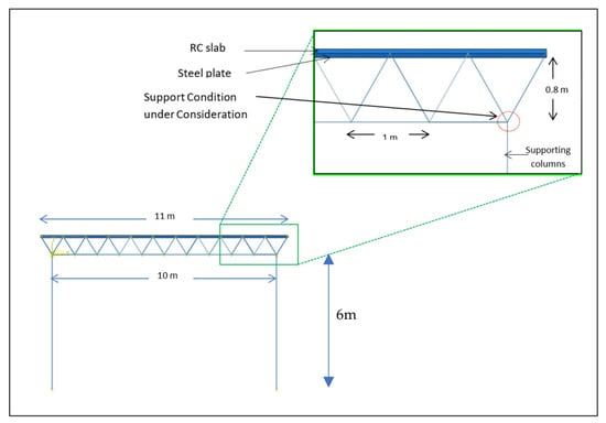
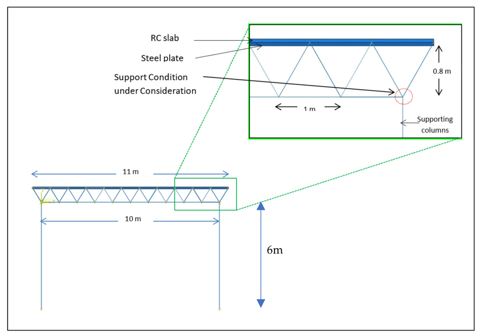
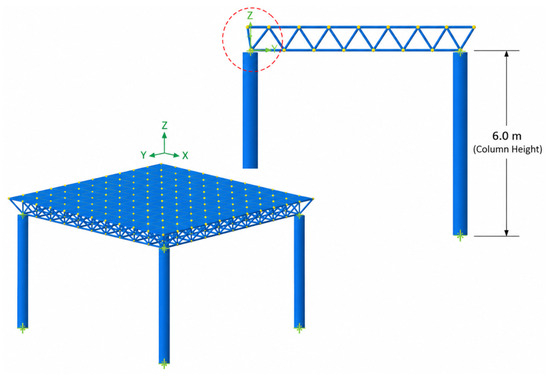
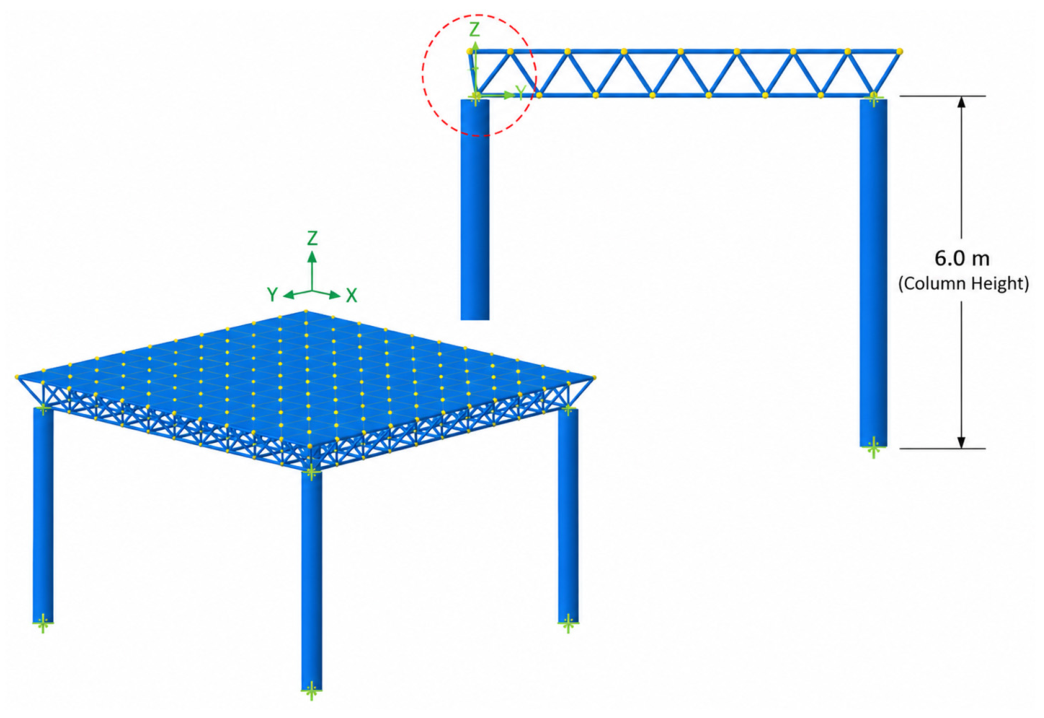
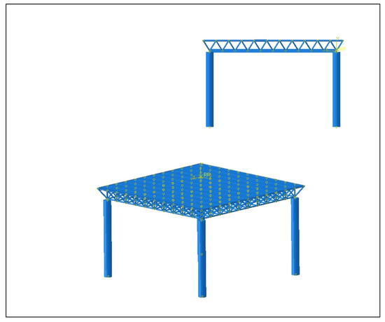
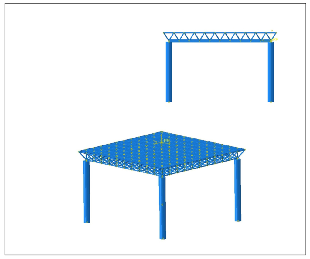
The structural model consisted of an orthogonal, square-pyramid-type, double-layer grid space frame spanning 11 m × 11 m and 0.8 m deep. Each module length was set at 1 m, creating a regular grid suitable for load distribution. The space frame supported a reinforced concrete (RC) deck measuring 11 m × 11 m, with a 0.5 m overhang on each side to simulate realistic slab overhang conditions, as shown in Figure 3. The slab thickness was 100 mm and reinforced with 6 mm BRC mesh spaced at 100 mm intervals in both directions, in accordance with ACI 318-19 [23]. Standard round-section cold-formed steel was used for the space frame components. The frame components consisted of a round pipe with a diameter of 7.5 cm and a column with a circular hollow section (CHS) with an outer diameter of 300 mm and a wall thickness of 10 mm. Additionally, a 1 mm thick curved steel plate was used to simulate curb elements. Figure 4 shows the model description. The supporting columns were 6.0 m tall, measured from the base support to the bottom layer of the space frame. This height was selected to represent a typical floor-to-floor height in space frame structures and significantly influences the system’s global stiffness, vibration period, and drift response.
Figure 3.
Plan view of 11 m × 11 m space frame layout and column locations. Node numbering is not shown for clarity.
Figure 4.
Side view of the modeled space frame.
Three identical models were created with a supporting system comprising the three alternative boundary conditions: 1. Simple Point Support—direct connection of the space frame to columns via hinged joints. 2. Inverted-Pyramid Support—a geometrically stable arrangement designed to improve load transfer and lateral stiffness. 3. Crosshead-Beam Support—where loads from the space frame were transmitted through intermediate beams spanning between the columns. These support conditions were selected to represent common engineering practices and to capture variations in structural response due to boundary conditions.
3.2. Material Modeling
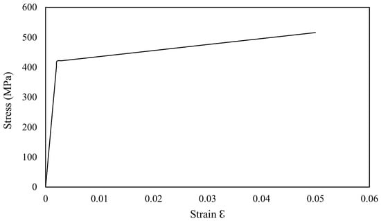
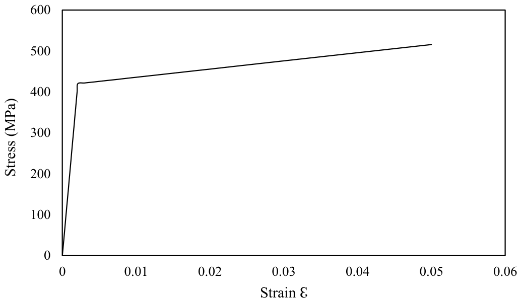
Steel members were modeled using an elastic–plastic constitutive relationship with isotropic strain hardening to capture yielding, post-yield ductility, and hysteretic energy dissipation under cyclic loading. The adopted steel properties equivalent to S420 were the elastic modulus Es = 200 GPa, yield strength fy = 420 MPa, ultimate tensile strength fu = 550 MPa, Poisson’s ratio , and density . The post-yield behavior was represented by using a bilinear strain-hardening model.
The elastic region is defined as [22]
The post-yield hardening region is expressed as
where the strain-hardening modulus was defined as
Moreover, the yield strain is
The elastic–plastic stress–strain relationship adopted in the finite element model is shown in Figure 5. The same material model was also adopted for reinforcing steel in the concrete.
Figure 5.
Elastic–plastic steel behavior used in the finite element simulation in accordance with the FIB Model Code.
The Concrete Damage Plasticity (CDP) model was employed to simulate the concrete slab. This model captures the nonlinear behavior of concrete in tension and compression. The Concrete Damage Plasticity (CDP) model was used to simulate nonlinear concrete behavior. The CDP is defined in terms of flow potential eccentricity ε = 0.1, dilation angle ψ = 35°, and viscosity parameter μ = 0.008. The ratio of the strength in the biaxial state to the strength in the uniaxial state, σbo/σco, is 1.16, and the ratio of the second stress invariant on the tensile meridian, Kc, is 0.666.
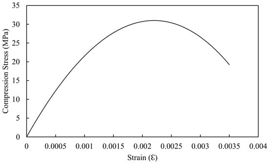
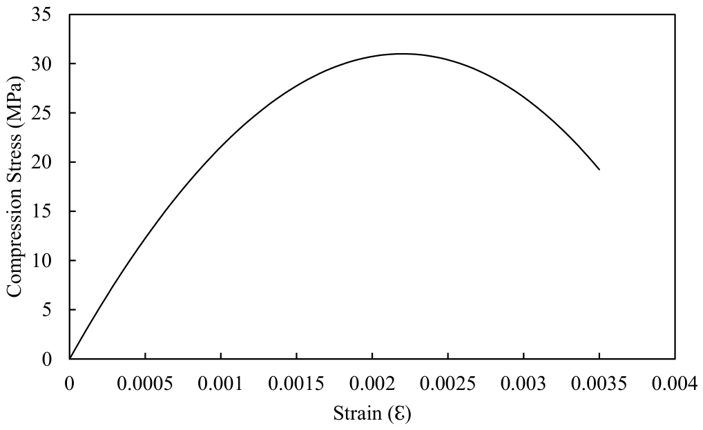
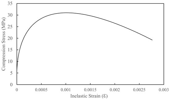
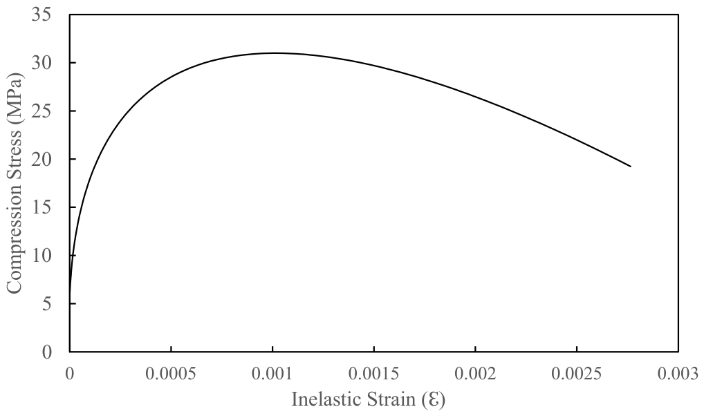
To model concrete using the CDP model in ABAQUS, the stress–strain relationship in compression and the post-failure stress–strain curve in tension are required. In this study, stress–strain data for compression and the post-failure curve were adopted in accordance with the FIB Model Code [24] and the constitutive model proposed by Chen (1995) [25]. The adopted concrete properties included an ultimate compressive strength of 31 MPa, an elastic modulus of 26 GPa, a density of 2400 kg/m3, and an ultimate strain of 0.001026. A linear stress–strain relationship following Hooke’s law was assumed up to approximately 50% of the ultimate compressive strength. Figure 6 shows the nonlinear concrete compression constitutive model adopted in the CDP finite element simulation, including both the linear-elastic and nonlinear-inelastic regions. The concrete compression hardening behavior implemented in the CDP model is presented in Figure 7.
Figure 6.
Nonlinear concrete compression constitutive model adopted in the CDP finite element simulation, in accordance with the FIB Model Code.
Figure 7.
Concrete compression hardening model adopted in the CDP finite element simulation according to the FIB Model Code.
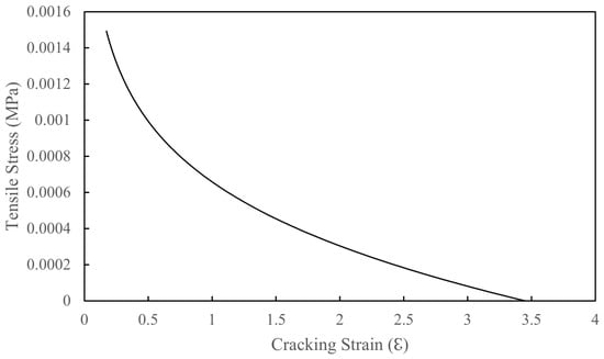
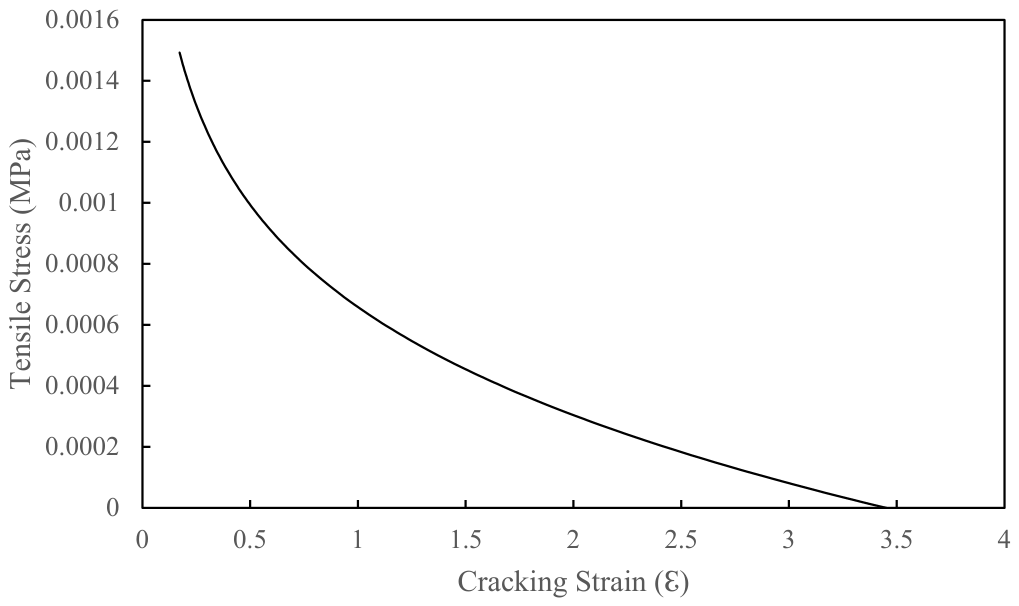
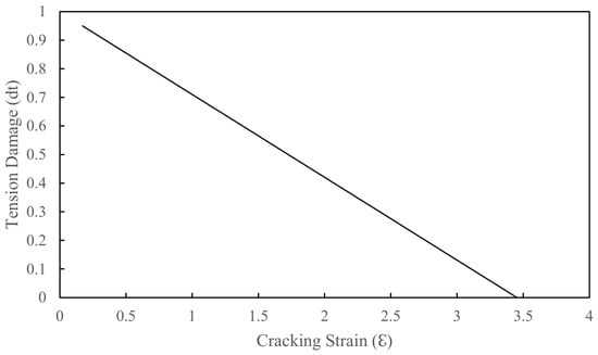
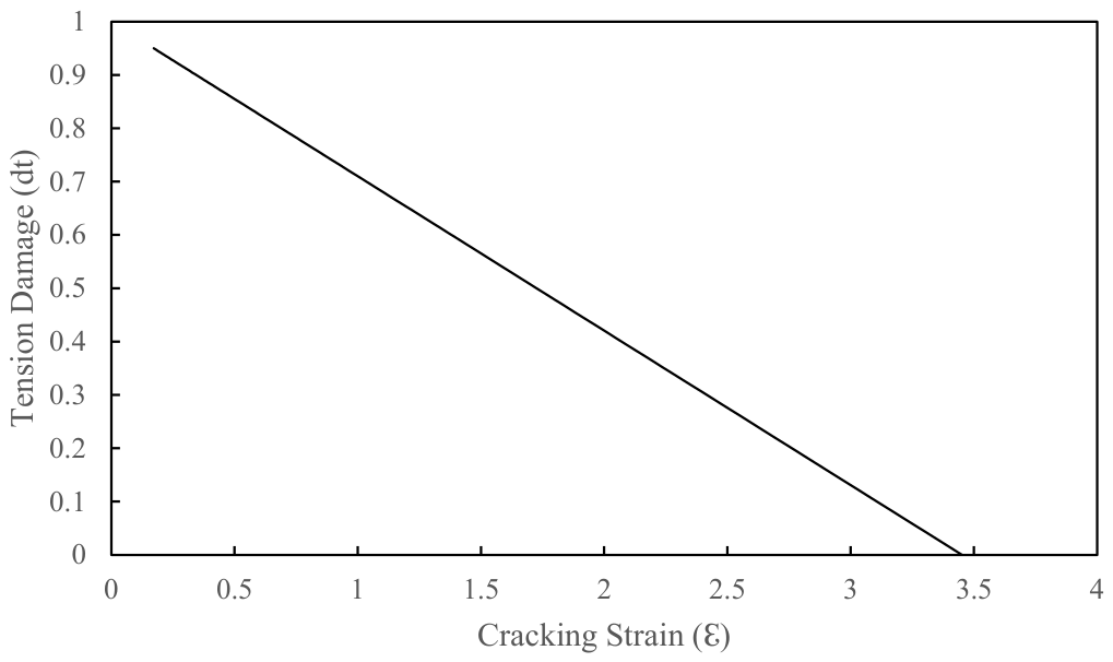
The tensile constitutive behavior used in the CDP model was developed using a fracture-energy approach in accordance with the CEB-FIP Model Code 2010. The developed tensile constitutive relationship captures the complete tension-stiffening response, including the initial linear-elastic stage, the tensile-strength peak, and the post-cracking softening behavior, expressed in terms of tensile stress versus cracking strain. The adopted concrete tension softening model used in the numerical simulation is shown in Figure 8. The post-cracking tensile behavior of concrete was modeled using a tension-stiffening approach. The tensile strength of concrete was taken as 7.4% of the compressive strength, in accordance with ACI 318-19 [23]. Additionally, tensile damage and compressive damage variables were incorporated to simulate progressive stiffness degradation under cyclic loading conditions. The adopted tensile damage evolution relationship used in the CDP model is shown in Figure 9. The Concrete Damage Plasticity model was fully defined to ensure reproducibility of the nonlinear finite element simulation. All constitutive relationships were developed in accordance with the CEB-FIP Model Code 2010 and calibrated using Chen (1995) [25]. The steel members were modeled as elastic–plastic materials with bilinear kinematic hardening to simulate cyclic yielding and hysteretic energy dissipation under reversed loading conditions. The constitutive model consists of an initial linear-elastic region followed by post-yield strain hardening to simulate plastic hinge formation and cyclic inelastic behavior.
Figure 8.
Concrete tension softening curve implemented in the CDP finite element simulation.
Figure 9.
Concrete tension damage applied in the CDP finite element simulation.
3.3. Finite Element Model
In this study, three-dimensional finite element (FE) models were developed using ABAQUS. The primary aim of the finite element simulation was to assess lateral displacement, base shear, and hysteretic behavior. The analysis results are used to explore how the support configuration impacts the space frame behavior.
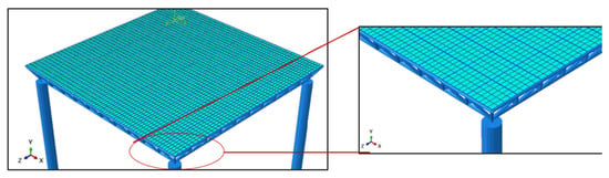
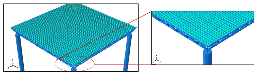
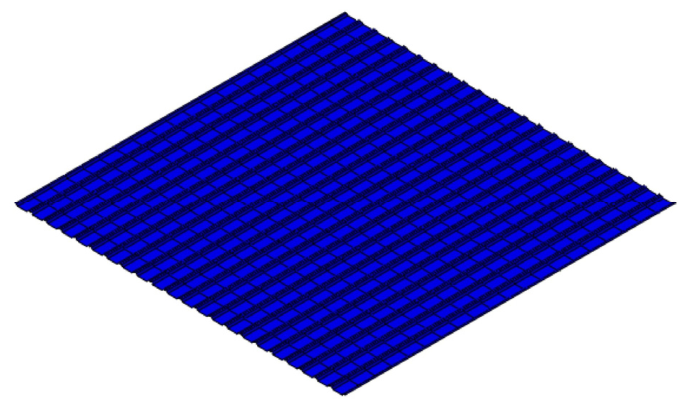
The FE model depicts the actual space frame of the building, with reinforced concrete used throughout. Figure 10 shows the mesh for the space frame. The model consists of space frame cold-formed round hollow sections with an outer diameter of 75 mm and a thickness of 5.2 mm. Columns are modeled as hollow sections (CHSs) with an outer diameter of 300 mm and a wall thickness of 10 mm, simulating curb elements. To improve analysis accuracy and better capture stress concentrations, the mesh density was increased near the supports.
Figure 10.
Mesh of the space frame.
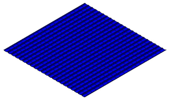
A 20-node reduced-integration brick element, C3D20R, was used to model a reinforced concrete slab with a maximum mesh size of 0.25 cm. The reinforcement bars were modeled using two-node linear elements embedded in the concrete slab (T3D3). The space frame was modeled using three-node quadratic beam elements (B32). The curb elements were represented with S8R shell elements. Table 1 summarizes the element types and their respective mesh densities. Figure 11 illustrates the finite element mesh for the slab and reinforcement.
Table 1.
Element types and mesh details of the finite element model.
Figure 11.
Mesh of the slab and reinforcement.
The slab and curb elements were subjected to self-weight and a uniformly distributed live load. Full loading was applied to all elements. The interaction between the slab, curb, and space frame was simulated using tie constraints because they are fully bonded. The interactions between the slab and curb, and between the curb and the space frame, are modeled as surface-to-surface and point-to-surface tie constraints, respectively.
Table 2 displays the types of connections employed between components in the ABAQUS finite element model. The connection between the concrete and reinforced-concrete parts was defined as an embedded region to ensure full interaction between them. A tie constraint with surface-to-surface behavior modeled the interaction between the concrete and the curb. In contrast, a tie constraint with point-to-surface behavior was applied between the curb and the space frame structure.
Table 2.
Interaction and constraint conditions applied in the finite element model.
3.4. Load
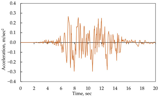
Three types of loads were applied in the model: self-weight was applied as a body force using material density definitions. Live load was simulated as a uniformly distributed surface load of 1 kN/m2, in accordance with EN 1991-1-1 [26] recommendations for public spaces. The seismic load consisted of a 20 s earthquake excitation applied along the X-axis at the supports. The excitation was represented using a recorded real earthquake ground motion scaled to match the design response spectrum, as shown in Figure 12.
Figure 12.
An earthquake for 20 s was applied to the supports of the space frame in the X-direction only.
In this study, a single representative ground-motion record was adopted to evaluate and compare the seismic performance of the proposed structural models under identical loading conditions. The selected record was chosen because it realistically represents earthquake characteristics in terms of intensity, duration, and time-varying behavior, enabling accurate nonlinear time-history analysis of the structural response. The use of a single seismic input also helped maintain consistency in comparative assessment and reduce computational cost associated with nonlinear finite element simulations. However, using multiple ground motion records could provide a more comprehensive evaluation of record-to-record variability and seismic performance.
3.5. Boundary Conditions
The supports were idealized to replicate realistic anchorage behavior, with full translational restraint at the base nodes and varying degrees of rotational freedom according to the chosen support condition.
The boundary conditions applied in the finite element model are summarized in Table 3. Translational degrees of freedom (U1, U2, U3) and rotational degrees of freedom (UR1, UR2, UR3) were assigned depending on the support configuration. The boundary conditions were defined in terms of translational and rotational degrees of freedom (DOFs). Translational DOFs (U1, U2, U3) represent displacements along the global axes, while rotational DOFs (UR1, UR2, UR3) represent rotations about these axes. The applied boundary conditions for each support configuration are summarized in Table 3.
Table 3.
Boundary condition for each support condition.
The geometric configuration of the support systems is defined as follows. Simple Point Support: The space frame is directly connected to the top of the column, without intermediate members. Inverted-Pyramid Support: Inclined members connect the top of the column to multiple nodes in the lower layer of the space frame, forming an inverted pyramid with a base width of 0.3 m. The base width of the pyramid is measured between the connection points at the space frame level. Crosshead-Beam Support: Horizontal steel beams with a rectangular cross-section of 300 mm × 200 mm are used to connect adjacent columns. These beams transfer loads from the space frame nodes to the columns.
The selected support configurations represent practical structural systems with different restraint characteristics and load-transfer mechanisms commonly used in long-span spatial structures. The investigated cases were chosen to compare the influence of boundary stiffness and geometric support arrangement on the seismic performance of the space frame system under consistent loading and modeling conditions.
To facilitate comparison between the investigated support systems, the boundary conditions were defined in terms of the translational (U1, U2, and U3) and rotational (UR1, UR2, and UR3) degrees of freedom available in ABAQUS. In all three cases, the translational degrees of freedom were fully restrained. The primary difference between the support configurations lies in the rotational restraint. Case 1 was modeled as an idealized pinned support with all rotational degrees of freedom released. Case 2 provides partial rotational restraint through the inclined support members of the inverted-pyramid system. In Case 3, the crosshead-beam restrains rotations about the X- and Y-axes (UR1 and UR2), while rotation about the Z-axis (UR3) remains free. These different restraint conditions were adopted to evaluate the influence of support rotational stiffness on the seismic behavior of the space frame system.
4. Case Studies
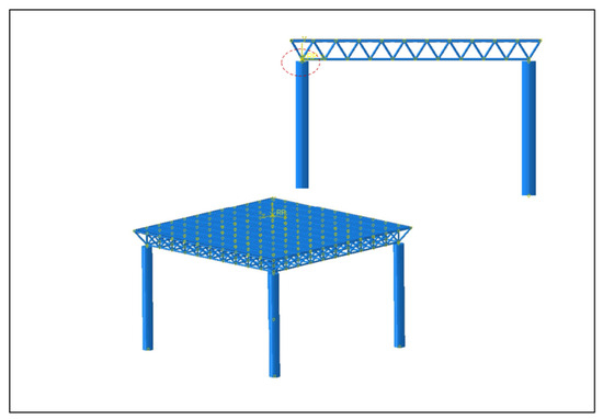
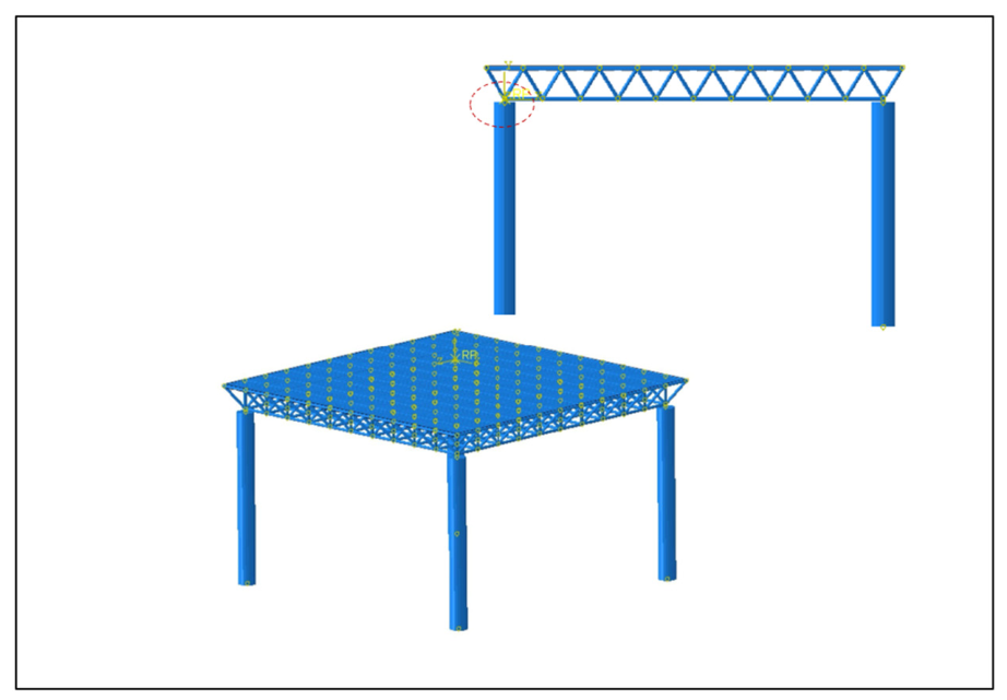
Case 1 (Simple Point Support): The space frame support node is connected directly to the top of the steel column, as shown in Figure 13 and Figure 14. The connection was modeled as an idealized pinned support, with translational degrees of freedom restrained and rotational degrees of freedom released, consistent with the boundary conditions reported in Table 3.
Figure 13.
Modeling of simple point support.
Figure 14.
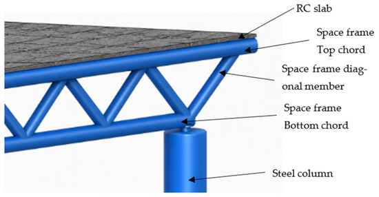
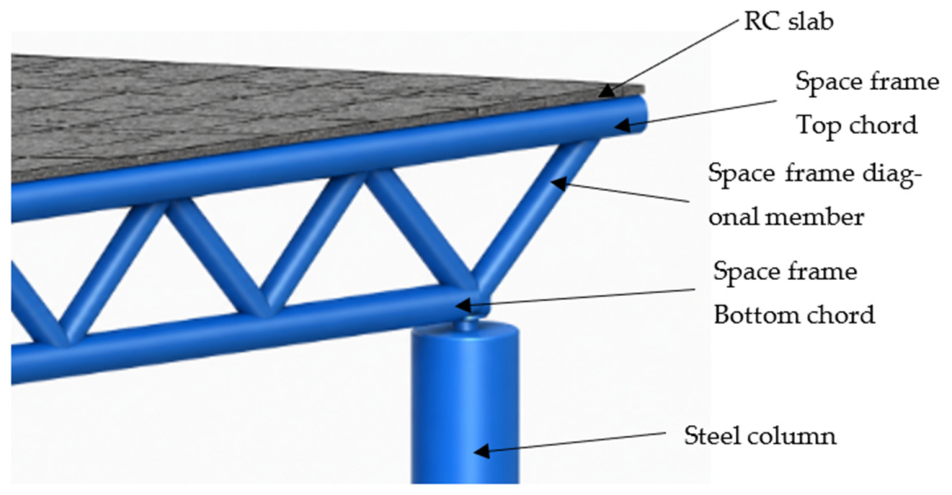
Details of the simple point support configuration.
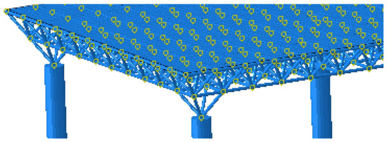
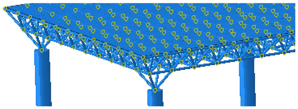
Case 2: Inverted-Pyramid Support: The structure is supported by columns arranged in an inverted pyramid, enhancing structural stability and improving load distribution, as shown in Figure 15 and Figure 16.
Figure 15.
Modeling of an inverted-pyramid support.
Figure 16.
Finite element model showing the inverted-pyramid support configuration.
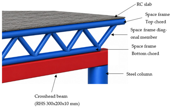
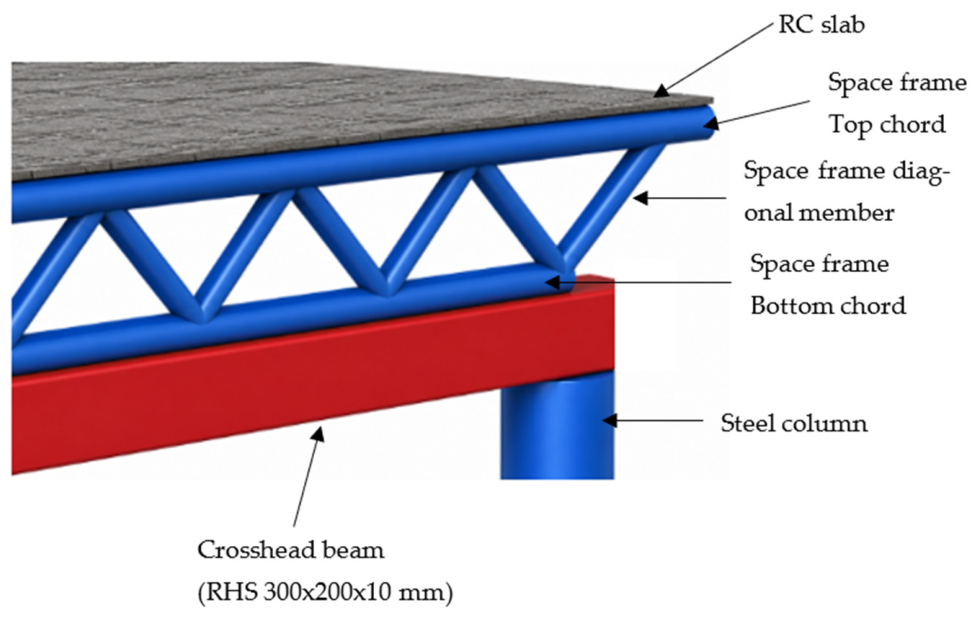
Case 3: Simple crosshead-beam support: The space frame is supported by a simple crosshead-beam spanning between the columns, ensuring effective load transfer, as shown in Figure 17 and Figure 18. Unlike the simple point support configuration (Case 1), the crosshead-beam support system (Case 3) includes continuous perimeter steel beams positioned between the columns and the space frame bottom chord. These beams act as intermediate load-transfer members distributing the forces from the space frame to the supporting columns. The crosshead members were modeled as rectangular hollow steel sections (RHS) with overall dimensions of 300 mm × 200 × 10 mm. The perimeter crosshead beams were connected to the bottom chord nodes of the space frame using tie constraints to ensure compatible displacement and complete force transfer between the connected members.
Figure 17.
Modeling of simple crosshead-beam support.
Figure 18.
Details of the crosshead-beam support configuration.
From the numerical modeling perspective, the crosshead beam provides additional rotational restraint at the connection between the space frame and the supporting columns. Accordingly, the support was modeled with U1, U2, and U3 restrained, UR1 and UR2 restrained, and UR3 released, as summarized in Table 3. Compared with the Simple Point Support (Case 1), this configuration provides greater resistance to bending rotations. Compared with the Inverted-Pyramid Support (Case 2), the crosshead beam offers a different load-transfer mechanism by increasing rotational stiffness through the connecting beam rather than through inclined support members.
Figure 14, Figure 16 and Figure 18 present detailed views of the support configurations adopted in the finite element model. In Case 1 (Simple Point Support, Figure 14), the space frame support node is directly connected to the top of the steel tubular column, resulting in the direct transfer of gravity and seismic loads from the space frame to the supporting column without any intermediate structural element. In Case 2 (Inverted-Pyramid Support, Figure 16), a system of inclined tubular members forms an inverted pyramid beneath the space frame. The structural loads are transferred from the space frame support nodes through the inclined members to a common bottom node connected to the column head, thereby modifying the load-transfer path and promoting force redistribution within the support system. In Case 3 (Crosshead-Beam Support, Figure 18), a rectangular hollow section (RHS) steel crosshead beam with external dimensions of 300 × 200 mm and a wall thickness of 10 mm is introduced between the space frame support nodes and the steel column. The crosshead beam acts as an intermediate load-transfer element, distributing support reactions over a larger area and increasing the stiffness of the support region. Consequently, the load-transfer mechanism and structural response differ from those of the direct-support configuration adopted in Case 1.
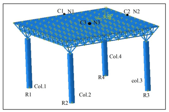
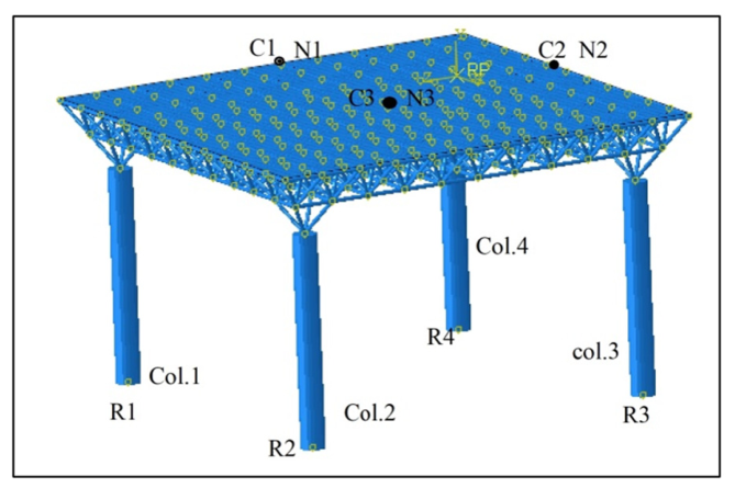
Three structural models were developed corresponding to the different support configurations, as shown in Figure 13, Figure 14, Figure 15, Figure 16, Figure 17 and Figure 18. For each case, the responses of six key monitoring points (three on the slab and three at the space frame nodes) were tracked under dynamic excitation as shown in Figure 19. Output parameters included maximum displacements in both X and Y directions, column drift, base shear, and hysteresis curves. These indicators were chosen because they represent critical aspects of seismic performance, including lateral stiffness, energy dissipation, and stability.
Figure 19.
Key points on the structure.
5. Numerical Verification of the Finite Element Model
Because experimental data or benchmark results for the specific composite space frame configuration considered in this study were unavailable, direct validation of the finite element model was not possible. Therefore, the numerical model was verified through: (i) implementation of the established Newmark-beta time-integration scheme; (ii) calibration of Rayleigh damping parameters in accordance with published recommendations; and (iii) a mesh-convergence study. The findings, therefore, should be considered as a comparative numerical assessment of how various support configurations affect the structural response, rather than as experimentally validated predictions of the system’s absolute behavior.
A transient dynamic analysis was conducted to evaluate the structure’s time-dependent response in terms of displacement, base shear, and hysteretic behavior. The Newmark-beta method with constant average acceleration (γ = 0.5 and β = 0.25) was adopted for numerical time integration. This approach is unconditionally stable for linear dynamic analysis and is widely used in structural dynamics applications (Chopra, 2020 [15]; Paultre, 2011 [27]). The displacement, velocity, and acceleration responses were calculated according to Equations (1)–(3), respectively.
To represent structural energy dissipation, Rayleigh damping was incorporated into the finite element model. The mass- and stiffness-proportional damping coefficients were calibrated to achieve a 5% damping ratio in the fundamental vibration mode, following the recommendations of Chopra (2020) [15].
The displacement in the current time step is
The velocity at the current time step :
And the acceleration at the current time step is
For the average acceleration approach, and .
k, m, and c represent the global stiffness, mass, and damping matrices, respectively; is the external load vector at time step ; is the time increment; , , and denote displacement, velocity, and acceleration, respectively, while and are the Newmark integration parameters.
Furthermore, a mesh convergence study was performed to verify the numerical accuracy of the finite element model. Five mesh sizes were investigated: 1.0 cm, 0.75 cm, 0.50 cm, 0.25 cm, and 0.125 cm. The results obtained using mesh sizes of 0.25 cm and 0.125 cm were identical, with a maximum variation of approximately 0.01%, indicating mesh convergence and numerical stability. Since the 0.125 cm mesh required greater computational time without significant improvement in accuracy, the 0.25 cm mesh size was adopted for the final simulations.
6. Results
The structural response of the double-layer space frame with a concrete slab was examined under seismic excitation using dynamic analysis methods. Displacements in both the X and Y directions were measured at six critical points—three on the concrete slab (C1–C3) and three on the steel space frame (N1–N3). These points were carefully chosen to represent areas of maximum expected deformation during loading. Figure 19 shows their location on the structure.
The analysis also involved assessing column displacements, base shear, and hysteresis for all cases.
6.1. Displacement Analysis
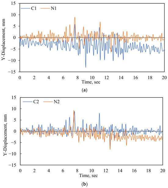
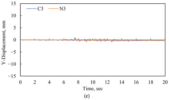
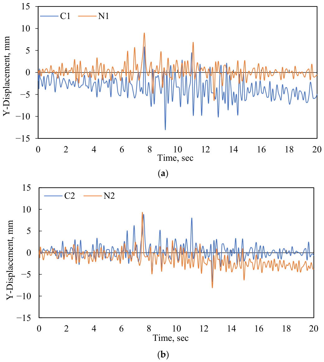
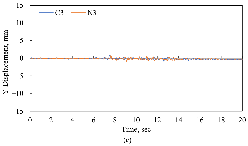
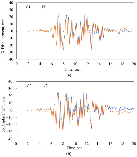
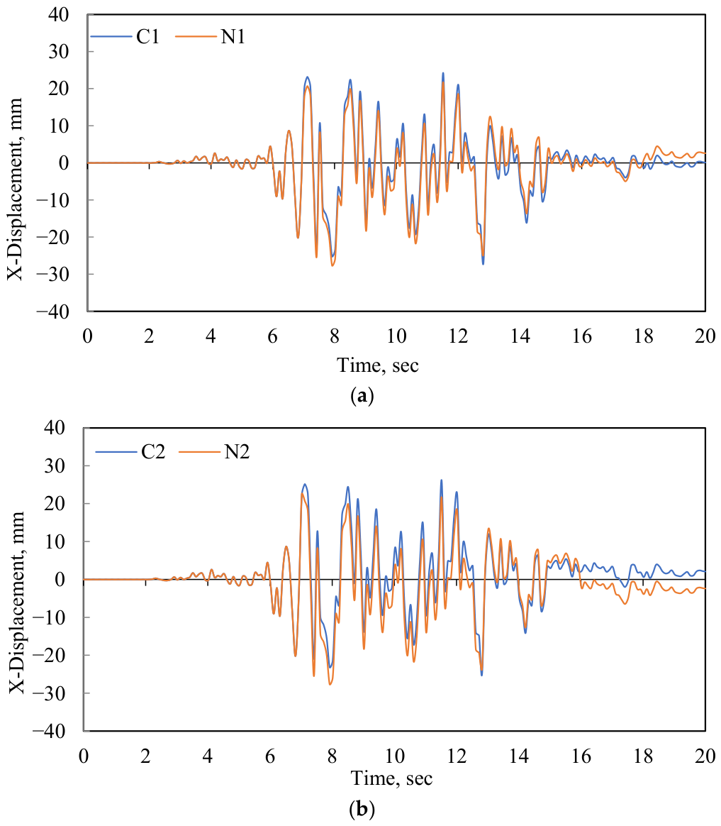
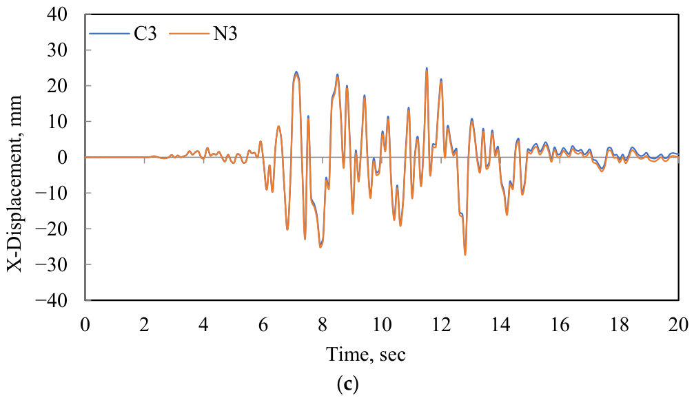
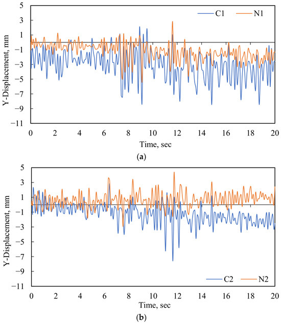
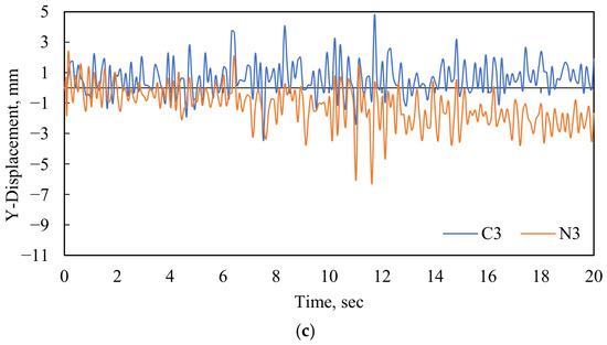
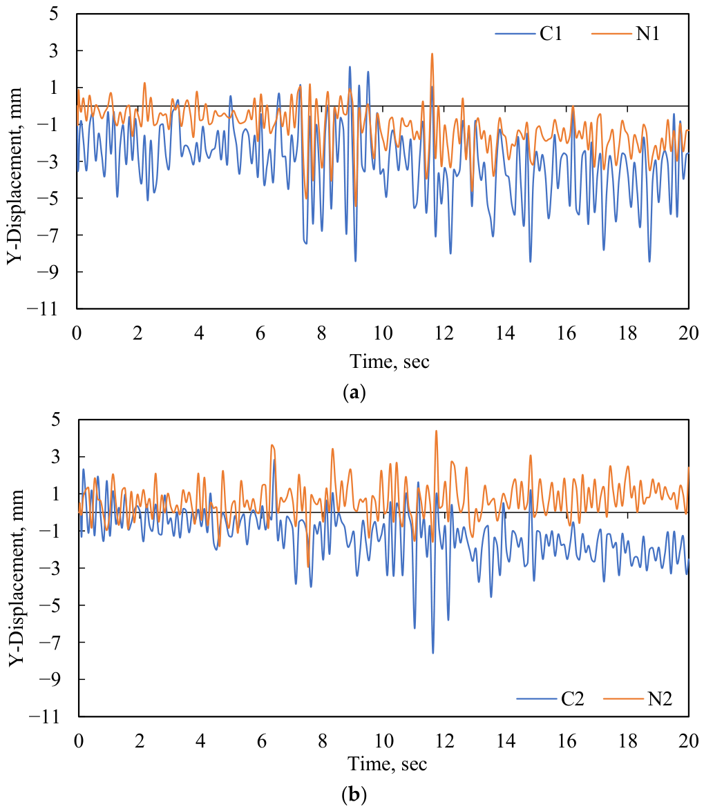
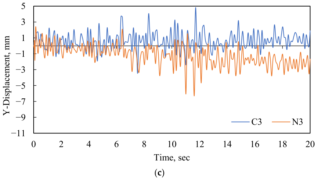
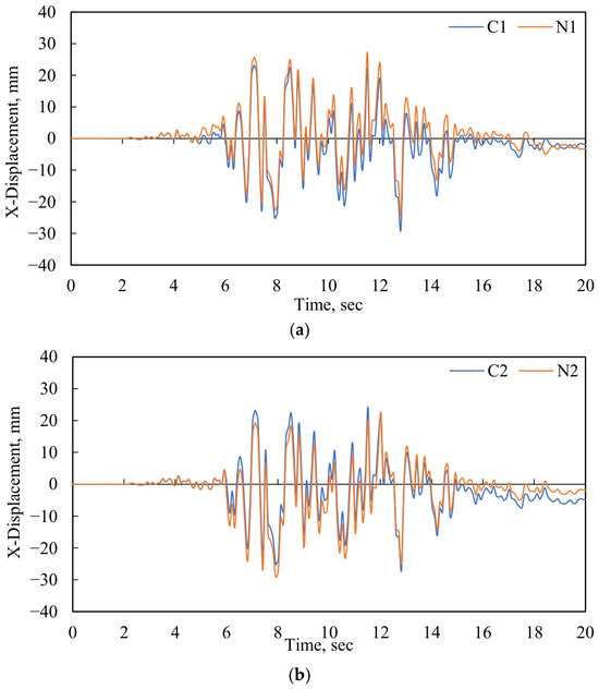
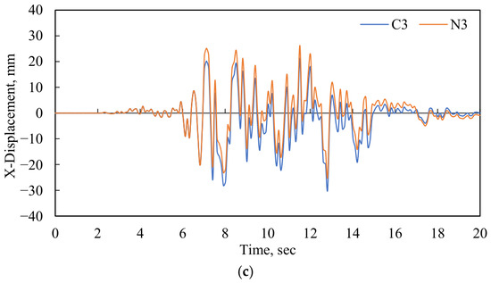
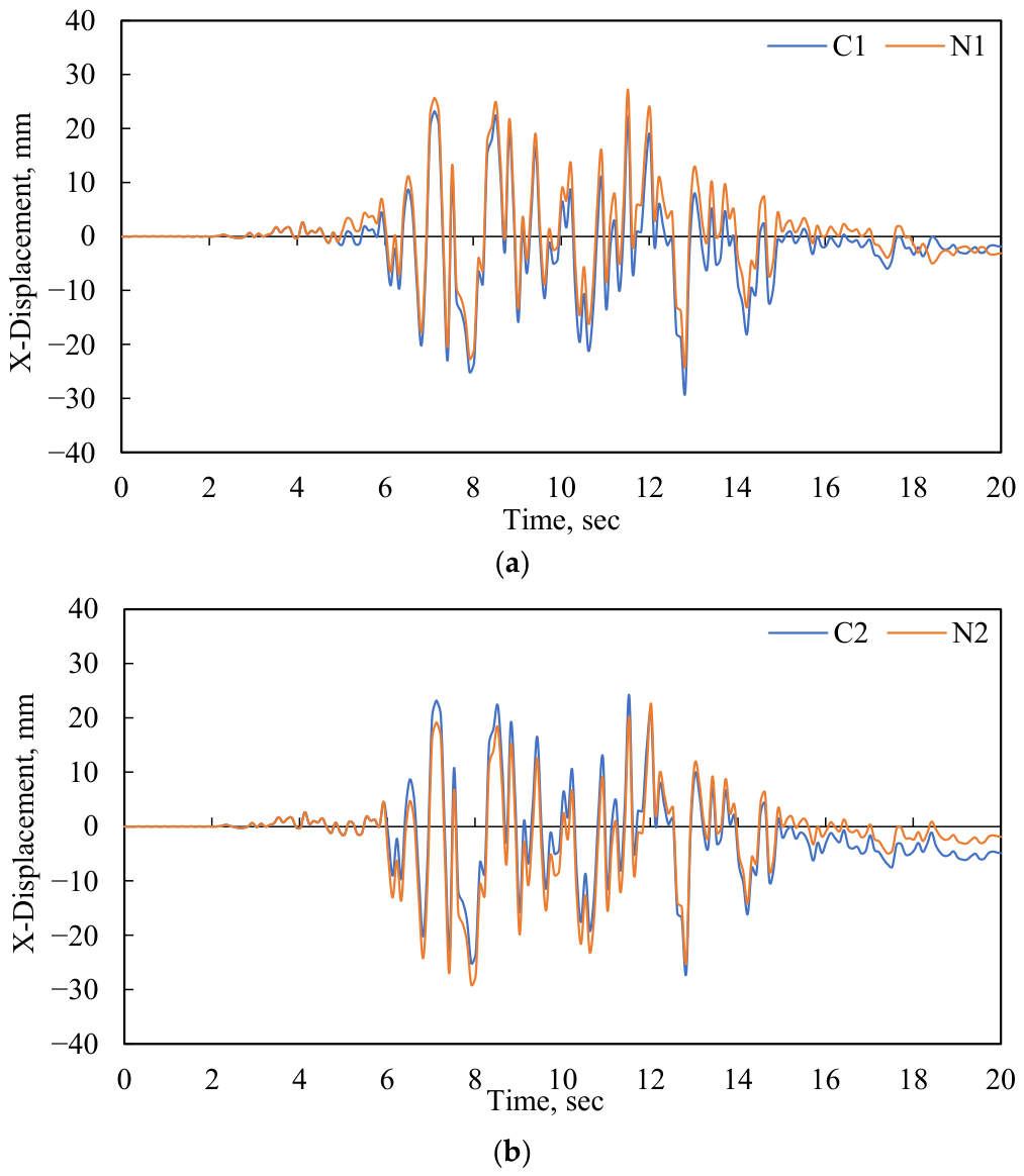
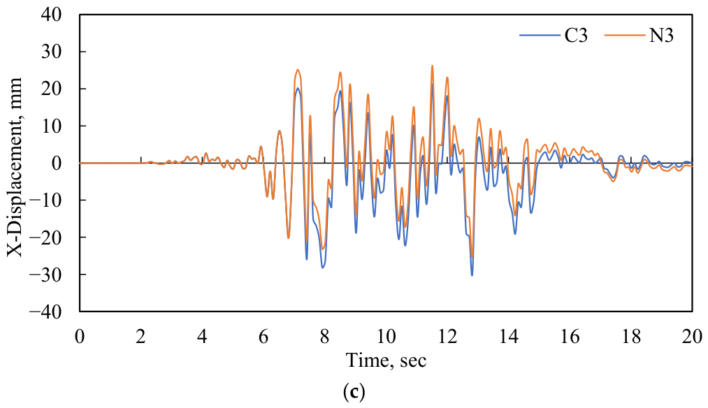
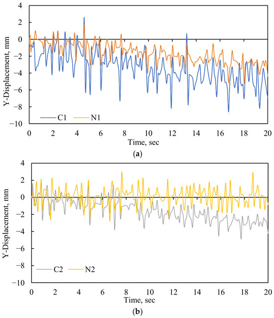
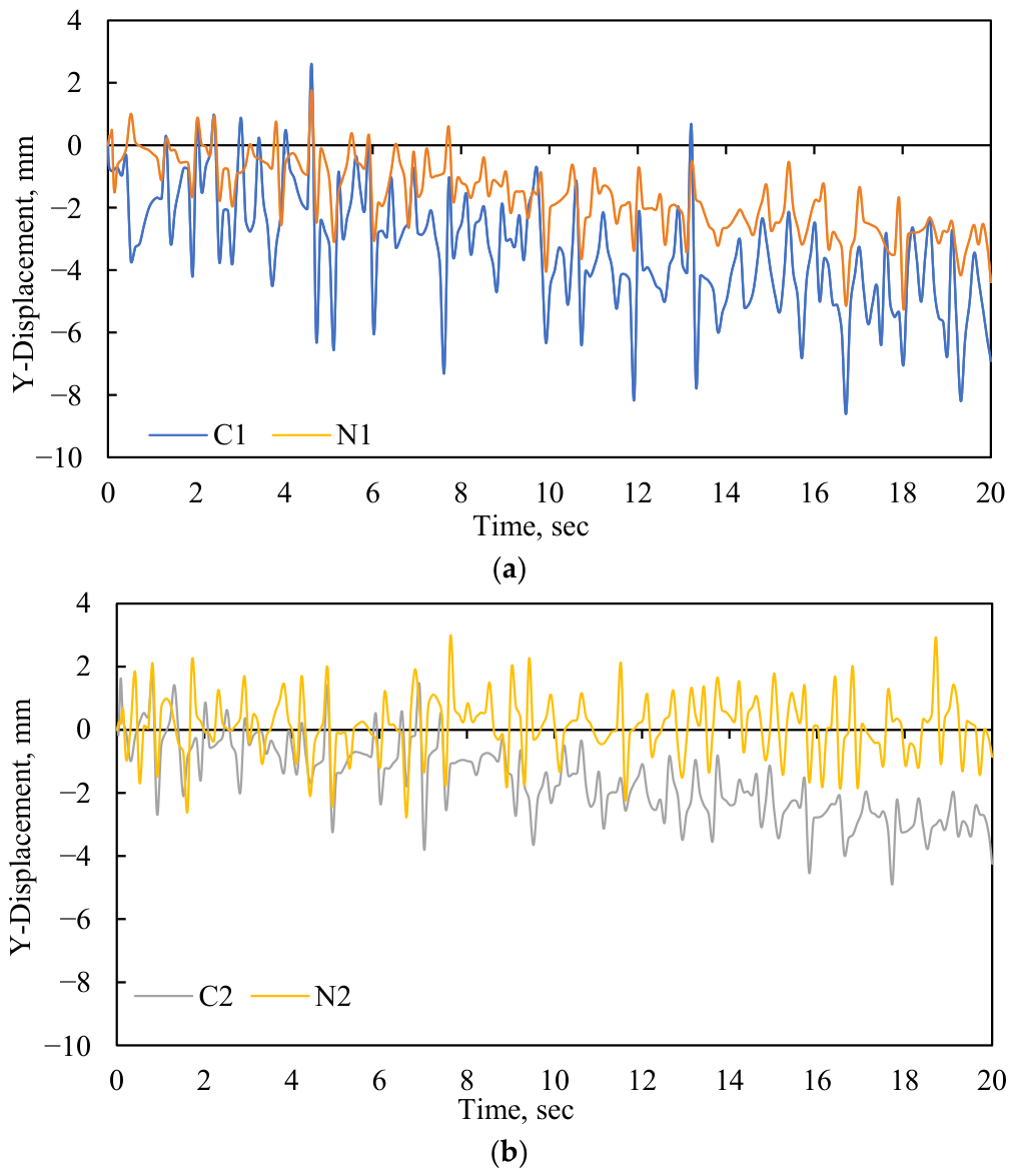
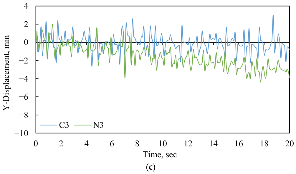
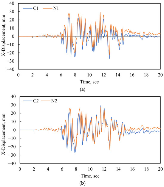
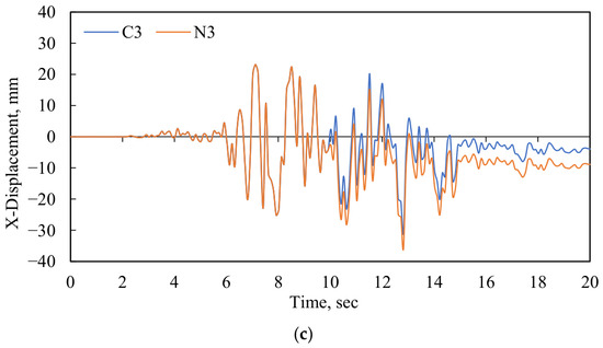
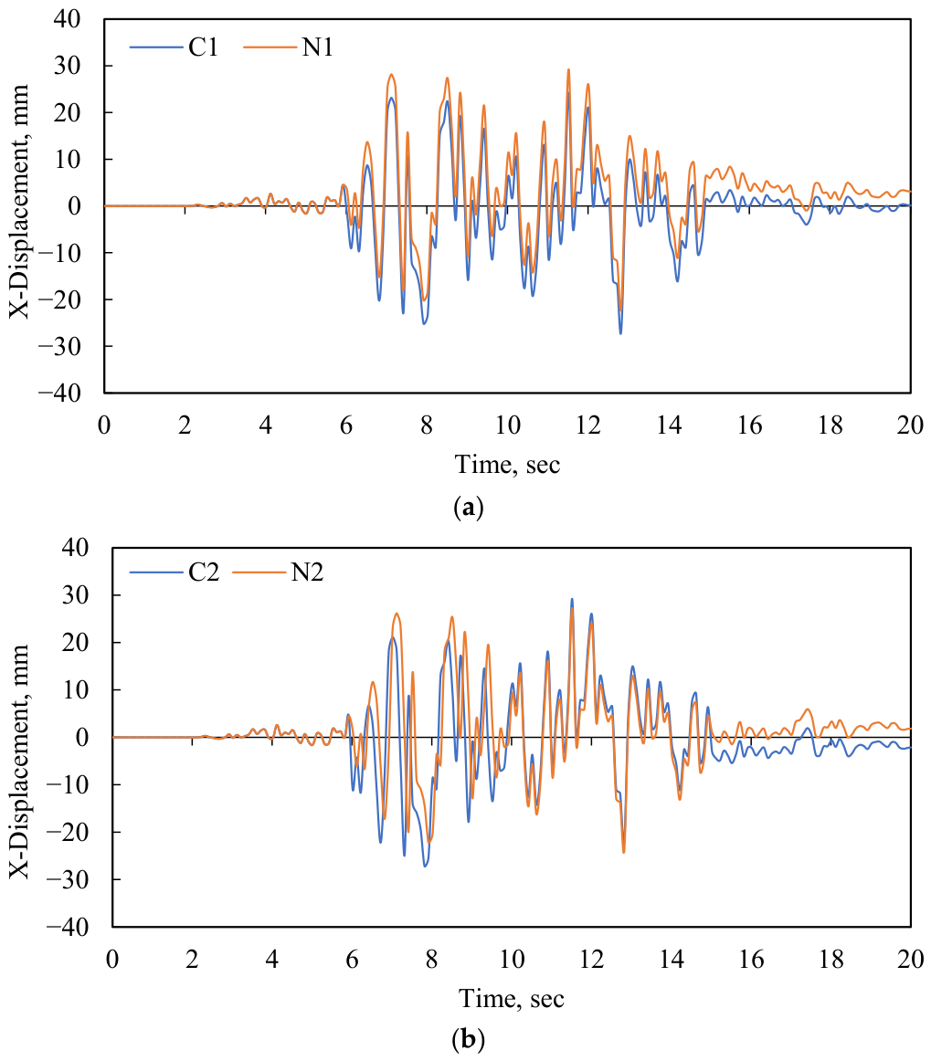
Figure 20, Figure 21, Figure 22, Figure 23, Figure 24 and Figure 25 illustrate the displacements in the Y and X directions for each case. Figure 20 and Figure 21 show the displacements in the Y and X directions from the analysis of the space frame with a simple point support. The results indicate that the maximum displacement in the X direction is 28 mm, occurring at key points C1 and N1. The maximum deflection (displacement in the Y direction) was found to be 12.5 mm at key points C1 and N1. Table 4 presents the maximum displacement in the X and Y directions for all the support cases.
Figure 20.
Y-direction displacement for simple point support; (a) key points C1, N1, (b) key points C2, N2, (c) key points C3, N3.
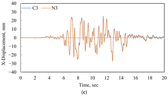
Figure 21.
X-direction displacement for simple point support; (a) key points C1, N1, (b) key points C2, N2, (c) key points C3, N3.
Figure 22.
Y-direction displacement for an inverted-pyramid support; (a) key points C1, N1, (b) key points C2, N2, (c) key points C3, N3.
Figure 23.
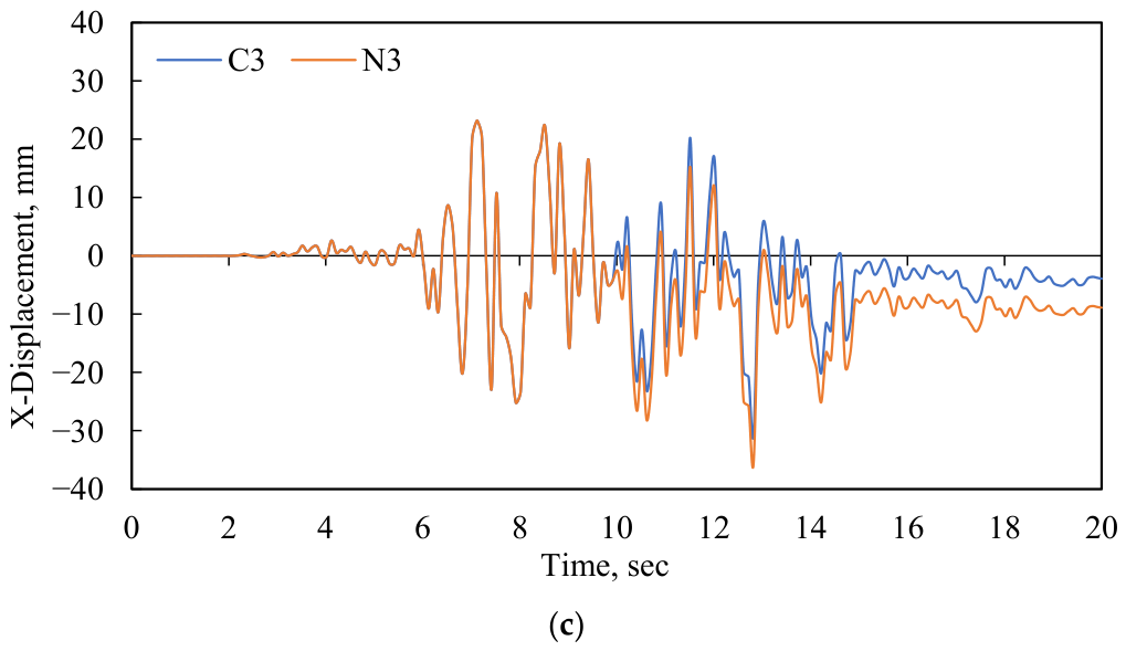
X-direction displacement for an inverted-pyramid support; (a) key points C1, N1, (b) key points C2, N2, (c) key points C3, N3.
Figure 24.
Y-direction displacement for simple crosshead-beams support; (a) key points C1, N1, (b) key points C2, N2, (c) key points C3, N3.
Figure 25.
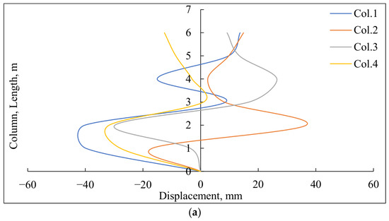
X-direction displacement for simple crosshead-beam support; (a) key points C1, N1, (b) key points C2, N2, (c) key points C3, N3.
Table 4.
Max. displacements in X and Y directions.
The results indicate that the simple point support showed the smallest displacement magnitudes in the X direction. However, this configuration showed the largest displacement in the Y-direction, indicating lower vertical stiffness and greater structural flexibility under seismic loading. In addition, larger vibration amplitudes and residual oscillations were observed after the peak excitation period between 5 and 15 s.
The inverted-pyramid support reduced the Y-direction displacements to 8.3 mm, representing a 33.6% reduction compared with the simple point support. This behavior indicates improved vertical stiffness and more effective energy dissipation, as shown in Figure 20, Figure 21, Figure 22, Figure 23, Figure 24 and Figure 25. The maximum displacement in the X-direction for this case was 29 mm. The displacement histories also showed more stable oscillation behavior and reduced residual response after the strong-motion phase.
In contrast, the crosshead-beam support exhibited the highest displacements with a maximum value of 35 mm, while the Y-direction displacement reached 8.4 mm, indicating a less efficient load-transfer mechanism and increased structural flexibility during seismic events. As shown in Figure 24, this support condition exhibited intermediate behavior relative to the other investigated cases in terms of lateral displacement response, indicating moderate lateral stability.
The displacement histories presented in Figure 20, Figure 21, Figure 22, Figure 23, Figure 24 and Figure 25 indicate that the main structural response was concentrated during the strong ground-motion duration between approximately 5 and 15 s, where the largest vibration amplitudes and displacement peaks occurred for all investigated support cases.
Compared with the simple point support, the inverted-pyramid support reduced the maximum Y-direction displacement from 12.5 mm to 8.3 mm, corresponding to a reduction of approximately 33.6%. In contrast, the crosshead-beam support reduced the Y-direction displacement by approximately 32.8%. However, the crosshead-beam support increased the maximum X-direction displacement by nearly 25% compared with the simple point support.
6.2. Column Displacement
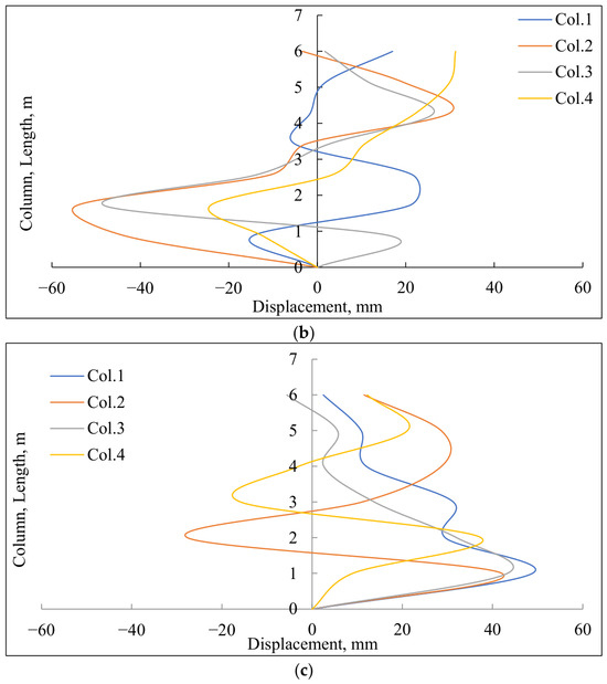
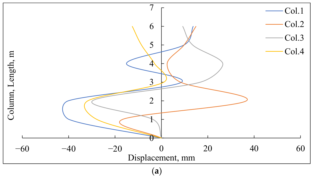
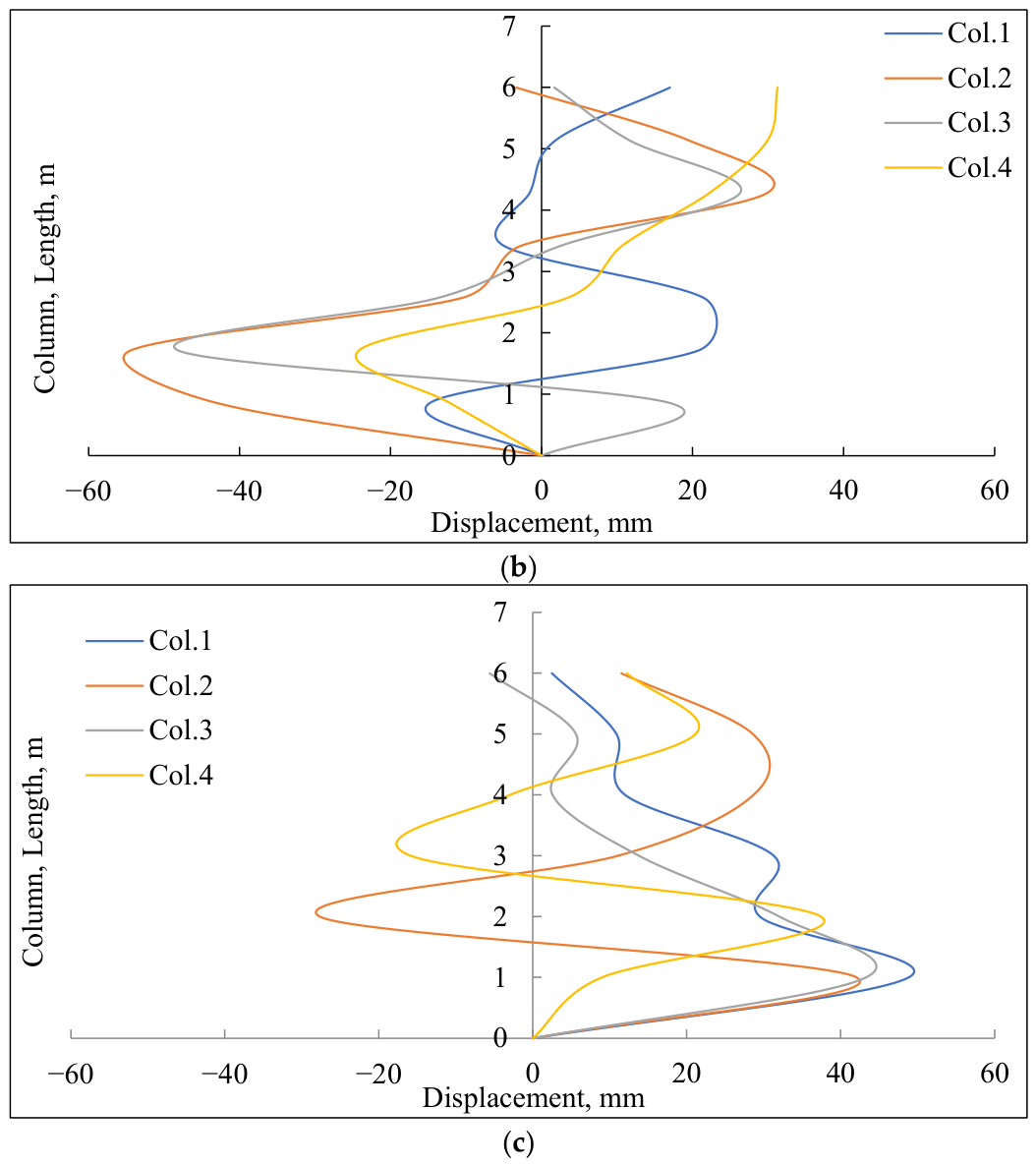
Figure 26 shows the deflection of columns in the X-direction for all investigated support conditions. Figure 26a shows that the maximum lateral deflection of the column under simple point supports reaches nearly 45 mm at mid-height. Figure 26b presents the lateral deflection for an inverted support. The results show a larger displacement of 55 mm at around 2.25 m, while, as shown in Figure 26c, the maximum displacement is 48 mm for the crosshead-beam support at 1.25 m.
Figure 26.
Displacement in X-direction along column length; (a) simple point support, (b) an inverted-pyramid support, (c) simple crosshead-beams support.
The results indicate that the simple point support showed the lowest column displacement among the supported cases, demonstrating better anchorage, whereas the inverted-pyramid support exhibited the largest lateral column deformation. The crosshead-beam support demonstrated intermediate behavior between the other two support configurations.
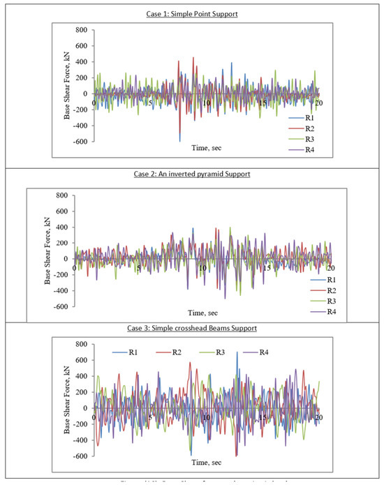
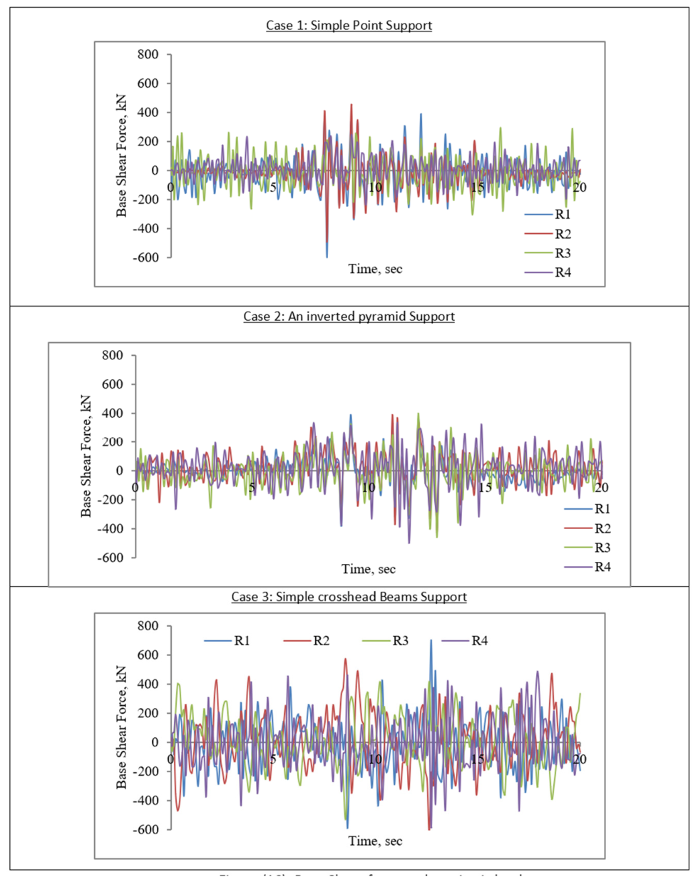
6.3. Base Shear
The base shear force, as shown in Figure 27, indicates that the support configuration significantly affects the distribution of seismic forces within the structure. The simple point support exhibited larger fluctuations in base shear response during the strong-motion interval. The inverted-pyramid support condition exhibited more stable base shear behavior with reduced response variability, indicating better absorption and redistribution of seismic forces. In contrast, the crosshead support exhibited higher and more fluctuating shear responses at the base.
Figure 27.
Base shear force under seismic load, support, simple crosshead-beam support.
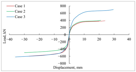
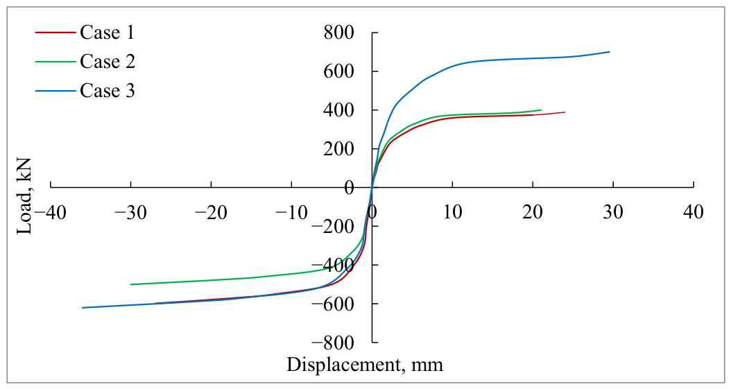
Finally, the skeleton and hysteretic curves, as shown in Figure 28, indicated that all investigated support systems exhibited acceptable energy-dissipation capacity under cyclic seismic loading. The crosshead-beam support exhibited larger hysteresis loop areas, higher load capacity, and improved ductility. In contrast, the inverted-pyramid configuration exhibited lower residual deformation and improved displacement control, whereas the crosshead-beam configuration demonstrated the greatest ductility and energy-dissipation capacity.
Figure 28.
The skeleton curves for three load cases.
6.4. Bearing Capacity and Deformation Performance
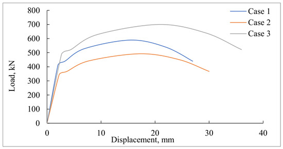
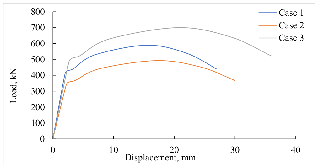
A load–displacement analysis was conducted until failure to evaluate the nonlinear behavior and hysteretic response of the investigated support systems. The results showed apparent variations in displacement patterns, load capacity, and force distribution depending on the type of structural support employed, as shown in Figure 29.
Figure 29.
The bearing capacity for three cases.
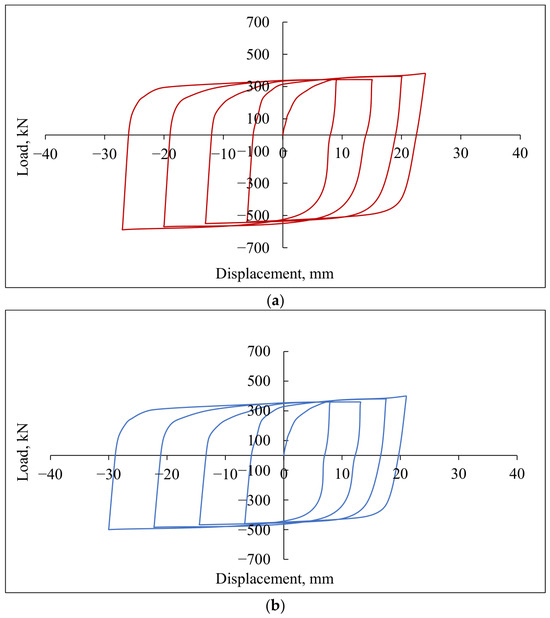
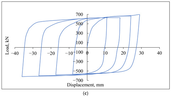
The hysteretic response curves of the space frame under cyclic seismic load for the three cases of support are shown in Figure 30. For Case 1, simple point support, the zero-force displacement in the first loop varies from +22.5 mm to −5.0 mm, while the corresponding force ranges from +382 kN to −550 kN. Similar behavior was observed for the remaining loading cycles and support configurations. The detailed force and displacement values for all investigated cases are summarized in Table 5.
Figure 30.
Hysteretic curves for a simple space frame under seismic load; (a) simple point support, (b) an inverted-pyramid support, (c) simple crosshead-beams support.
Table 5.
Zero-force displacement and forces for hysteretic response.
Each loop in the curves shown in Figure 30 has a steep initial elastic range, beyond which the yield region begins, after which the curves tend to flatten and show large displacement with a slight increase in force, indicating moderate strain hardening. The initial unloading curves are also steep, indicating high stiffness of the frame. The wide loops and the large area under these curves indicate that the three frame cases exhibit high energy-dissipation capacity, which is of exceptional importance in structures designed to resist seismic forces.
The high positive and negative displacements in each loop, accompanied by increasingly high positive and negative forces, indicate that the frames have acceptable ductility, as evidenced by their ability to withstand displacement without a sudden loss of strength.
A comparison of the frame responses for the three cases shows that case three has a higher capacity for energy dissipation than the other two. This is obvious from the larger area under the loops of this case compared to the areas under the curves of the other cases. Case 3 also exhibits higher ductility than the other cases. This is due to the wider range of displacement and higher values of forces compared to the other cases.
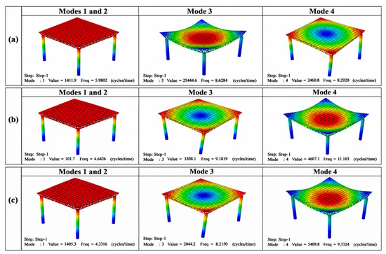
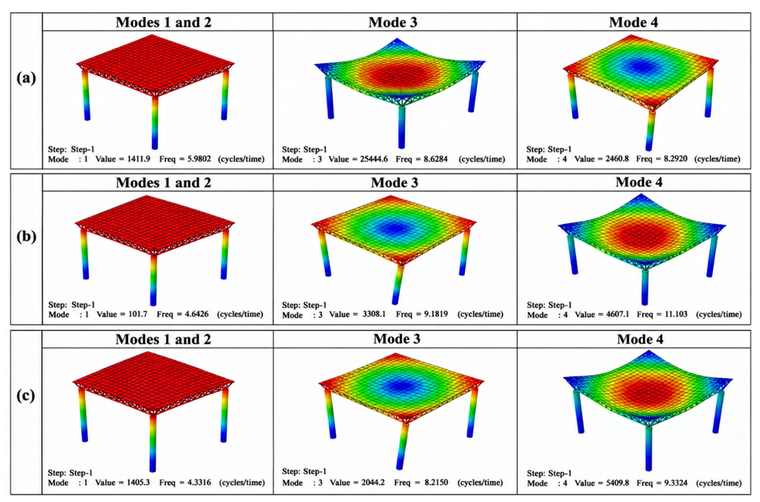
The shapes of the first modes of free vibration for the three cases are shown in Figure 31. The first and second modes for the three cases are horizontal sway and are almost identical for each case; they are shown by one shape. The second mode in Case 1 was a vertical deflection of the roof, while the fourth one was a torsional motion. The second and third modes of Cases 2 and 3 are torsional and vertical deflection of the roof, respectively. It is worth noting that these later modes are in the reverse arrangement of those for Case 1.
Figure 31.
Shapes of the first three modes of vibration for the three cases, (a) Case 1, (b) Case 2, and (c) Case 3.
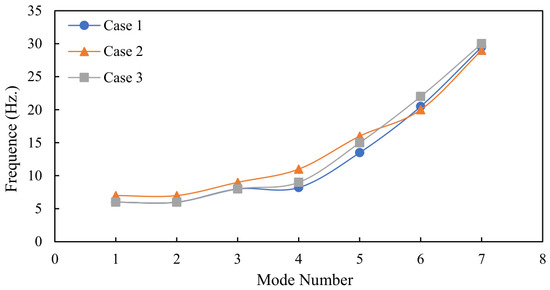
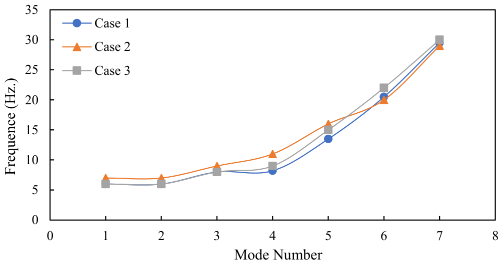
The relation between mode number and the natural frequency of the first seven modes for the three cases is shown in Figure 32.
Figure 32.
The variation in natural frequency with mode number.
6.5. Pushover Analysis
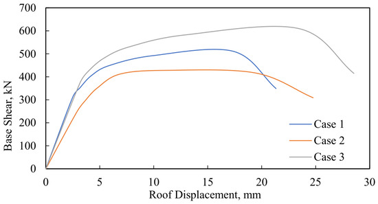
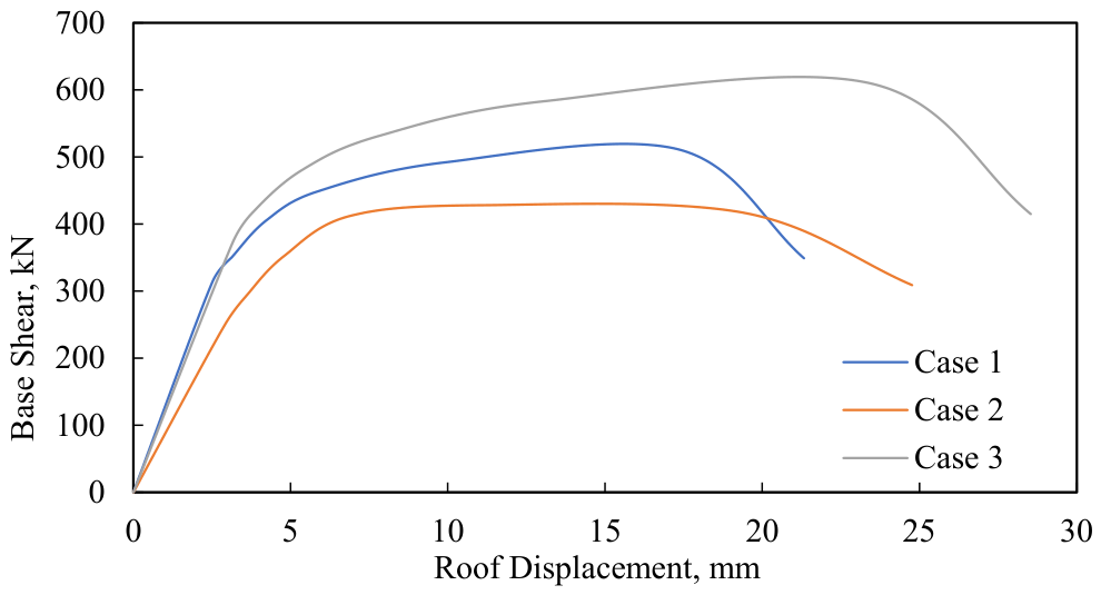
To further evaluate the nonlinear seismic performance of the investigated space frame systems, a displacement-controlled pushover analysis was performed in ABAQUS for all three support configurations. Geometric nonlinearity was activated using the NLGEOM option. Adaptive stabilization was employed with a dissipated energy fraction of 0.0002 and a maximum stabilization-to-strain energy ratio of 0.05 to improve numerical convergence during the nonlinear response analysis. The analysis was conducted with an initial increment size of 0.001, a minimum increment of 1 × 10⁻⁵, and a maximum increment of 0.01. Figure 33 presents the pushover capacity curves relating the base shear to the roof displacement for the three investigated support systems. The curves clearly demonstrate that the support configuration significantly influences the lateral stiffness, strength, and post-yield deformation.
Figure 33.
Relation between base shear and roof displacement.
Behavior of the double-layer space frame system. The crosshead support system exhibited the highest base shear capacity and the largest roof displacement before significant strength degradation occurred. The maximum base shear reached approximately 620 kN, with a roof displacement approaching 28.5 mm, indicating enhanced lateral resistance and superior energy-dissipation capability. The wider response curve observed in Case 3 reflects improved structural ductility and a more stable nonlinear response under increasing lateral loading. Case 2 exhibited intermediate behavior relative to the other support systems. Although the initial stiffness was acceptable, the structure experienced earlier degradation of post-peak strength than in Case 3. The maximum base shear was lower, and the nonlinear response exhibited reduced deformation capacity, indicating a moderate level of seismic performance.
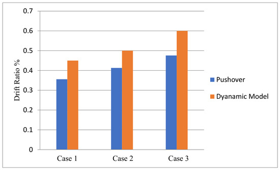
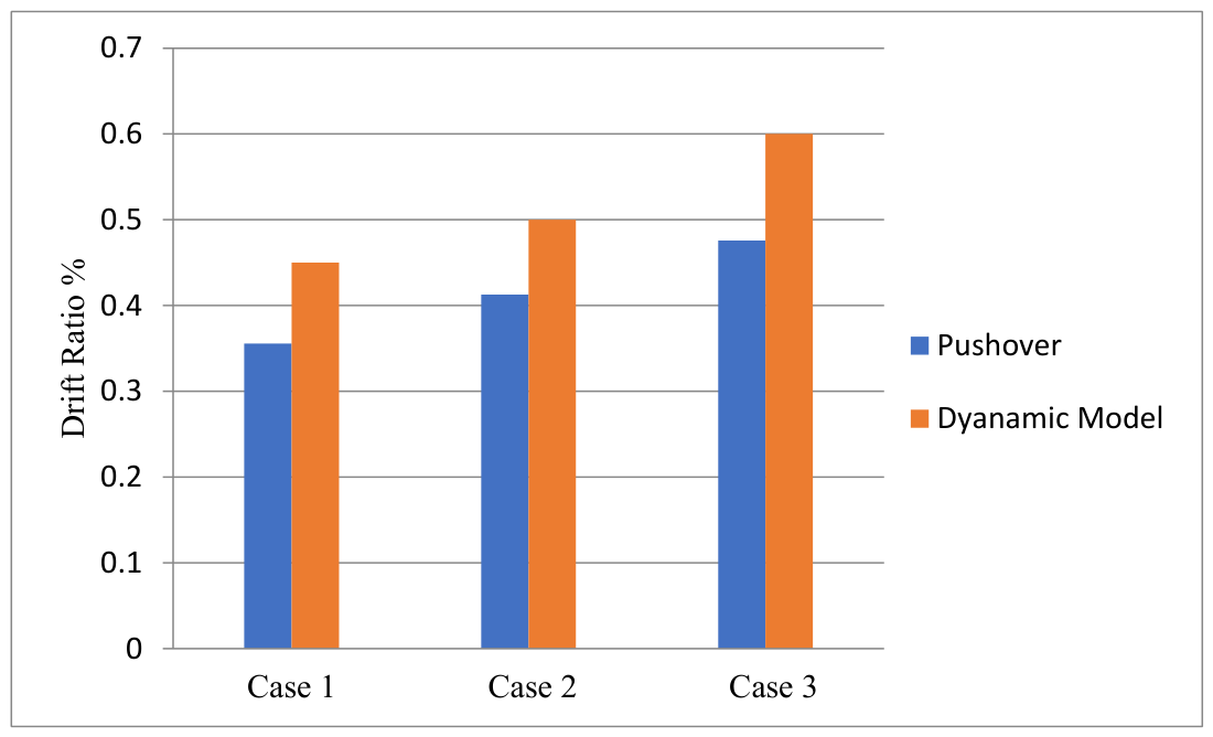
Case 1 demonstrated the weakest seismic behavior among the investigated cases. The structure exhibited lower base shear resistance and a narrower nonlinear response range, indicating limited ductility and reduced energy dissipation capacity. Furthermore, the post-peak degradation occurred earlier than in the other configurations, reflecting a less efficient load transfer mechanism and increased structural flexibility during seismic excitation. Table 6 summarizes the ductility ratios obtained from the pushover analysis. The ductility ratio increased from 5.05 in Case 1 to 5.18 in Case 2, and then to 5.35 in Case 3. Similarly, the ultimate roof displacement increased progressively from 21.329 mm in Case 1 to 24.762 mm in Case 2 and, finally, to 28.542 mm in Case 3. These results confirm that the support configuration plays an important role in improving the nonlinear deformation capacity and seismic resistance of the structural system. The comparison between the pushover analysis and the nonlinear dynamic analysis through the drift ratio evaluation showed good agreement between the two approaches, as illustrated in Figure 34. The obtained drift ratios remained within acceptable seismic performance limits, while the relative ranking of the three support systems remained consistent in both analyses. This agreement enhances the reliability of the numerical model and confirms the effectiveness of the proposed support configurations under seismic loading conditions. Overall, the pushover analysis showed that the inverted-pyramid support configuration provided the greatest displacement-control capability and stiffness enhancement, whereas the crosshead-beam support exhibited the highest ductility and energy-dissipation capacity. The results also demonstrate that support conditions significantly affect the structural behavior of composite double-layer space frames subjected to earthquake excitation.
Table 6.
Ductility for pushover analysis.
Figure 34.
Drift ratio for three cases and two types of analysis.
7. Discussion
The numerical results indicate that the boundary support configuration significantly influences the seismic response of double-layer space frame composite systems with reinforced concrete slabs. The observed variations in lateral displacement, base shear, and hysteretic behavior among the three investigated support conditions can be directly attributed to differences in load-transfer mechanisms, global stiffness distribution, and energy dissipation capacity.
The simple point support exhibited the largest vertical displacement (12.5 mm in the Y-direction; Table 4) and the largest residual oscillations in the displacement histories (Figure 20 and Figure 21), indicating lower support stiffness and less efficient force redistribution under seismic loading. This behavior indicates insufficient rotational restraint and limited transverse stiffness at the column–space frame interface, leading to increased structural flexibility and reduced energy dissipation efficiency under cyclic seismic loading. Similar trends were reported in previous analytical investigations of minimally restrained spatial frames, where inadequate boundary stiffness resulted in amplified dynamic response and reduced damping effectiveness.
The inverted-pyramid support configuration demonstrated the most effective displacement-control performance among the investigated support systems. It produced the smallest vertical displacement (8.3 mm), corresponding to approximately a 33.6% reduction compared with the simple point support (Table 4). The inclined support members created alternative load-transfer paths that increased the global stiffness of the structure and improved force redistribution, resulting in lower vertical displacements and reduced drift demand under seismic excitation. These characteristics contributed to improved structural stability and more uniform force transfer throughout the support region.
The crosshead-beam support configuration exhibited a different response mechanism. Although the crosshead-beam support produced the largest X-direction displacement (35 mm), it also exhibited the widest hysteresis loops and the highest ductility ratio (5.35; Table 6), indicating greater inelastic deformation capacity and energy dissipation than the other support systems. These results suggest that the increased stiffness provided by the crosshead beam promotes a more ductile structural response under cyclic loading. This behavior can be attributed to the increased stiffness and force redistribution provided by the crosshead beam, which promotes a more ductile structural response.
These results indicate that no single support configuration performed best across all performance criteria. The inverted-pyramid support provided the most favorable displacement control and structural stability, whereas the crosshead-beam support exhibited the greatest energy-dissipation capacity, ductility, and load-carrying performance under seismic loading.
Overall, the results confirm that optimizing support configuration can significantly enhance seismic performance without increasing member size or material consumption. This has important practical implications for the design of economical and resilient long-span spatial structures, particularly in moderate-to-high seismic regions. The findings suggest that boundary geometry may warrant further consideration in future research and potential design recommendations for composite space frame systems.
A yield verification procedure was conducted for all primary steel members using the von Mises stress criterion. The maximum equivalent stresses obtained from the finite element analysis were extracted and compared against the steel yield strength (fy = 420 MPa). The results indicated that localized regions within the column exceeded the yield stress during peak cyclic loading, confirming the development of inelastic behavior and the formation of plastic hinges. Therefore, the structural response cannot be considered purely elastic under the applied loading levels. The observed nonlinear hysteretic response and energy dissipation were primarily associated with yielding of the steel lateral force-resisting system, while additional stiffness degradation resulted from cracking and crushing of the concrete slab modeled using the Concrete Damage Plasticity (CDP) formulation.
8. Design Implications and Practical Recommendations
The findings of this study provide several important implications for the seismic design of long-span double-layer space frame systems, composite with reinforced concrete slabs. The demonstrated sensitivity of structural response to boundary support configuration indicates that support geometry should be considered an important parameter in seismic design rather than a secondary detailing consideration. Traditional reliance on simple point supports may lead to excessive lateral flexibility, increased residual deformation, and inefficient energy dissipation, all of which reduce seismic resilience and post-earthquake serviceability.
The improved displacement control behavior observed for the inverted-pyramid support highlights the effectiveness of geometrically stabilized load-transfer mechanisms in enhancing global stiffness and improving cyclic behavior without increasing material consumption or member size. From a practical engineering perspective, this suggests that optimizing the support configuration can achieve meaningful improvements in seismic performance while maintaining structural economy. Such an approach aligns with modern performance-based seismic design principles, where deformation control, energy absorption, and rapid post-event recovery are prioritized alongside strength requirements.
The intermediate response observed in crosshead-beam supports further indicates that partial stiffness enhancement alone is insufficient unless accompanied by efficient axial load redistribution and three-dimensional geometric restraint. Therefore, future structural design guidelines for spatial steel–concrete composite systems should explicitly incorporate boundary-condition optimization within early conceptual design stages rather than addressing it during final detailing.
For engineering applications in moderate-to-high seismic regions, the results suggest that support systems incorporating triangulated load paths may offer advantages, such as inverted-pyramid configurations or functionally equivalent geometries, by providing a stable hysteretic response. Implementing such systems can significantly reduce displacement demand, improve ductility, and enhance overall seismic reliability without substantial additional construction costs.
Finally, the study underscores the need for future research integrating experimental validation, broader parametric variation, and performance-based design metrics to translate numerical findings into codified engineering practice. Advancing this direction will support the development of resilient, economical, and sustainable long-span spatial structures suitable for next-generation infrastructure.
Table 7 summarizes the principal seismic performance indicators obtained for the three investigated support configurations. The table provides a direct comparison of displacement response, base shear capacity, ductility, stiffness characteristics, and overall seismic performance.
Table 7.
Summary of seismic performance indicators for the investigated support configurations.
The results of this study indicate that the support configuration affects the seismic response of double-layer space frame systems. The inverted-pyramid support showed improved displacement control and structural stability compared with the other investigated cases. In contrast, the simple point support exhibited greater displacement and residual deformation due to the lower stiffness at the support connection. The crosshead-beam support improved load-transfer behavior but resulted in greater displacement in the X-direction. Therefore, the selection of the support system should consider both stiffness and deformation behavior under seismic loading. The findings presented in this study are limited to the finite element models investigated and the seismic excitation applied. Additional studies using multiple earthquake records and experimental validation are recommended before extending the results to general design practice. However, the present study is limited to a single representative ground-motion record and numerical analysis, without experimental validation. Future studies should include multiple earthquake records and experimental verification to further evaluate the seismic behavior of space frame systems.
9. Conclusions
This study investigated the seismic behavior of double-layer composite space frames with reinforced concrete slabs under three different support conditions using nonlinear time-history analysis in ABAQUS. The numerical results indicate that the support configuration significantly influences the seismic response of the investigated structural system.
The simple point support exhibited the largest vertical displacement and residual deformation due to its lower stiffness and limited restraint. In contrast, the inverted-pyramid support showed improved structural stability and displacement control, reducing the maximum Y-direction displacement from 12.5 mm to 8.3 mm, a 33.6% reduction relative to the simple point support. The crosshead-beam support configuration exhibited the largest hysteresis-loop areas and the highest ductility ratio among the investigated cases, indicating greater energy-dissipation capacity and enhanced inelastic deformation capability under cyclic seismic loading.
The simple crosshead-beam support exhibited intermediate behavior compared with the other investigated cases. Although it improved load transfer and stiffness characteristics, the maximum X-direction displacement increased by approximately 25% compared with the simple point support. However, this support configuration exhibited larger hysteresis-loop areas and greater ductility, indicating improved energy-dissipation capacity.
The inverted-pyramid support provided the greatest reduction in displacement demand and stiffness enhancement, whereas the crosshead-beam support exhibited the highest ductility and energy-dissipation capacity. These findings suggest that the preferred support configuration depends on the specific seismic performance objective and design requirements.
The conclusions presented in this study are based on the investigated finite element models and the loading conditions considered. Further experimental investigations and analyses of additional structural configurations are recommended to extend the applicability of these findings.
Author Contributions
Conceptualization, A.Z.T., A.A.-M., H.A.A.-G., H.K.H. and A.A.K.; Methodology, A.Z.T., A.A.-M., H.A.A.-G., H.K.H. and A.A.K.; Software, A.Z.T., A.A.-M., H.A.A.-G., H.K.H. and A.A.K.; Validation, A.Z.T., A.A.-M., H.A.A.-G., H.K.H. and A.A.K.; Formal analysis, A.Z.T., A.A.-M., H.A.A.-G., H.K.H. and A.A.K.; Investigation, A.Z.T., A.A.-M., H.A.A.-G., H.K.H. and A.A.K.; Resources, A.Z.T., A.A.-M., H.A.A.-G., H.K.H. and A.A.K.; Data curation, A.Z.T., A.A.-M., H.A.A.-G., H.K.H. and A.A.K.; Writing—original draft, A.Z.T., A.A.-M., H.A.A.-G., H.K.H. and A.A.K.; Writing—review & editing, A.Z.T., A.A.-M., H.A.A.-G., H.K.H. and A.A.K.; Visualization, A.Z.T., A.A.-M., H.A.A.-G., H.K.H. and A.A.K.; Supervision, A.Z.T., A.A.-M., H.A.A.-G., H.K.H. and A.A.K.; Project administration, A.Z.T., A.A.-M., H.A.A.-G., H.K.H. and A.A.K.; Funding acquisition, A.Z.T., A.A.-M., H.A.A.-G., H.K.H. and A.A.K. All authors have read and agreed to the published version of the manuscript.
Funding
This research received no external funding.
Data Availability Statement
The original contributions presented in this study are included in the article. Further inquiries can be directed to the corresponding author.
Conflicts of Interest
The authors declare no conflict of interest.
References
- Lan, T.T. Space Frame Structures. In Handbook of Structural Engineering, 2nd ed.; Chen, W.F., Lui, E.M., Eds.; CRC Press: Boca Raton, FL, USA, 2005; pp. 24-1–24-49. [Google Scholar]
- International Association for Shell and Spatial Structures (IASS). Manual on the Design of Double-Layer Grids; IASS: Madrid, Spain, 1984. [Google Scholar]
- Ramaswamy, G.S.; Eekhout, M.; Suresh, G.R. Analysis, Design and Construction of Steel Space Frames; Thomas Telford Publishing: London, UK, 2002. [Google Scholar]
- Rizwan, S.A.; Bhatti, A.Q. On the performance of double-layer square-on-square grids. In Proceedings of the Fourth International Conference on Space Structures; Nooshin, N., Ed.; Thomas Telford Publishing: London, UK, 1993; Volume 1, pp. 614–621. [Google Scholar]
- Karamanos, S.A.; Karamanos, G.P. Seismic design of double-layer space grids and their supports. In Proceedings of the Fourth International Conference on Space Structures; Nooshin, N., Ed.; Thomas Telford Publishing: London, UK, 1993; Volume 1, pp. 476–484. [Google Scholar] [CrossRef] [Scilit]
- El-Sheikh, A. Approximate dynamic analysis of space trusses. Eng. Struct. 2000, 22, 26–38. [Google Scholar] [CrossRef] [Scilit]
- Moghaddam, H.A. Seismic behaviour of space structures. In Proceedings of the 13th World Conference on Earthquake Engineering (WCEE), Vancouver, Canada, 1–6 August 2004. Paper No. 523. [Google Scholar]
- Bezerra, L.M.; de Freitas, C.A.S.; Matias, W.T.; Nagato, Y. Increasing load capacity of steel space trusses with end-flattened connections. J. Constr. Steel Res. 2009, 65, 2197–2206. [Google Scholar] [CrossRef] [Scilit]
- Liu, Z.; Wang, X.; Zhou, Z.; Xue, J.; Lai, B.; Xu, J. Experimental and numerical study on seismic performance of steel reinforced concrete spatial frame with irregular section columns. Eng. Struct. 2021, 242, 112507. [Google Scholar] [CrossRef] [Scilit]
- Nie, J.; Fan, J.; Ding, Y. Seismic behavior of double-layer lattice space structures: Experimental and numerical investigation. Eng. Struct. 2020, 209, 109912. [Google Scholar]
- Jough, F.K.G.; Babaei, S. Seismic performance evaluation of space-frame structures using nonlinear static and time-history analyses. Ömer Halisdemir Üniversitesi Mühendis. Bilim. Derg. 2025, 14, 659–667. [Google Scholar] [CrossRef] [Scilit]
- Cui, Y. Dynamic characteristics of composite space frames with reinforced concrete slabs. Thin-Walled Struct. 2021, 162, 107593. [Google Scholar] [CrossRef] [Scilit]
- Wang, X.; Li, H.; Zhao, Y. Experimental study on seismic performance of steel–concrete composite space frames. J. Build. Eng. 2021, 44, 102949. [Google Scholar] [CrossRef] [Scilit]
- Fang, C.; Igarashi, A.; Takeuchi, T. Self-centering steel spatial structures with enhanced seismic resilience. Eng. Struct. 2022, 252, 113682. [Google Scholar] [CrossRef] [Scilit]
- Chopra, A.K. Dynamics of Structures: Theory and Applications to Earthquake Engineering, 5th ed.; Pearson Education: London, UK, 2020. [Google Scholar]
- Priestley, M.J.N.; Calvi, G.M.; Kowalsky, M.J. Displacement-Based Seismic Design of Structures; IUSS Press: Rome, Italy, 2007. [Google Scholar]
- Fardis, M.N. Seismic Design, Assessment and Retrofitting of Concrete Buildings; Springer: Cham, Switzerland, 2015. [Google Scholar] [CrossRef] [Scilit]
- Taymus, A.; Yilmaz, O.; Korkmaz, K.A. Seismic design optimization of steel space frame buildings equipped with triple friction pendulum base isolators. J. Build. Eng. 2024, 91, 109748. [Google Scholar] [CrossRef] [Scilit]
- Clough, R.W.; Penzien, J. Dynamics of Structures, 3rd ed.; McGraw-Hill: Columbus, OH, USA, 1993. [Google Scholar]
- Bathe, K.J. Finite Element Procedures; Prentice Hall: Upper Saddle River, NJ, USA, 1996. [Google Scholar]
- Cook, R.D.; Malkus, D.S.; Plesha, M.E.; Witt, R.J. Concepts and Applications of Finite Element Analysis; Wiley: Hoboken, NJ, USA, 2002. [Google Scholar]
- Dassault Systèmes. Abaqus Finite Element Analysis Software. SIMULIA. 2023. Available online: https://www.3ds.com/products/simulia/abaqus (accessed on 1 September 2025).
- American Concrete Institute. Building Code Requirements for Structural Concrete (ACI 318-19) and Commentary (ACI 318R-19); American Concrete Institute: Farmington Hills, MI, USA, 2019. [Google Scholar] [CrossRef] [Scilit]
- Fédération Internationale du Béton (FIB). FIB Model Code for Concrete Structures 2010; Ernst & Sohn: Berlin, Germany, 2013. [Google Scholar] [CrossRef] [Scilit]
- Chen, D. Stress-Strain Behavior of High-Strength Concrete Cylinders. Master’s Thesis, New Jersey Institute of Technology, Department of Civil and Environmental Engineering, Newark, NJ, USA, 1995. [Google Scholar]
- EN 1991-1-1:2002; Eurocode 1: Actions on Structures—Part 1-1: General Actions—Densities, Self-Weight, Imposed Loads for Buildings. European Committee for Standardization (CEN): Brussels, Belgium, 2002.
- Paultre, P. Dynamics of Structures; John Wiley and Sons: Hoboken, NJ, USA, 2011. [Google Scholar]

Disclaimer/Publisher’s Note: The statements, opinions and data contained in all publications are solely those of the individual author(s) and contributor(s) and not of MDPI and/or the editor(s). MDPI and/or the editor(s) disclaim responsibility for any injury to people or property resulting from any ideas, methods, instructions or products referred to in the content. |
© 2026 by the authors. Licensee MDPI, Basel, Switzerland. This article is an open access article distributed under the terms and conditions of the Creative Commons Attribution (CC BY) license.