


Abstract
To investigate the influence of different structural design parameters on the flexural performance of steel–UHTCC composite bridge decks and to determine reasonable ranges for these parameters, a finite element model was developed based on a literature review and existing experimental studies. The numerical results were then validated against experimental data, confirming the reliability of the model. Subsequently, a parametric study was conducted using the validated model, systematically considering the effects of rib thickness, rib height, steel deck thickness, UHTCC layer thickness, and longitudinal reinforcement ratio on the flexural behavior of the composite bridge decks, and recommendations for appropriate parameter values were proposed. The results indicate that increasing rib thickness and rib height is relatively cost-effective for improving the flexural performance of steel–UHTCC composite bridge decks, whereas increasing steel deck thickness and UHTCC layer thickness is less efficient in enhancing flexural performance. In addition, the amount of longitudinal reinforcement has a negligible effect on both the load-bearing capacity and stiffness of the composite bridge decks.
1. Introduction
The first steel–concrete composite structure in the world was constructed in the 1920s, since when composite structural systems have been widely used in building and bridge engineering [1]. Steel–concrete composite bridge decks achieve effective shear transfer through connectors such as shear studs, enabling the concrete slab and the underlying steel structure to act integrally under loading. In this way, the concrete component is primarily subjected to compression, while the steel component mainly resists tension, allowing both materials to fully exploit their respective advantages and develop composite action. However, steel–concrete composite bridge decks also exhibit several notable disadvantages. Cracking of concrete in regions under negative bending moments is an unavoidable issue in practical engineering, which leads to a reduction in overall structural stiffness and deterioration of deck durability. On the other hand, orthotropic steel deck systems are commonly adopted in composite bridge decks, resulting in complex structural configurations with numerous longitudinal and transverse ribs. This leads to a large number of welds in the deck system and pronounced stress concentration problems. Under repeated local wheel loads, such details are highly susceptible to fatigue cracking [2,3]. To address the aforementioned problems in steel–concrete composite bridge deck systems and to fully exploit the advantages of composite structures, the research team led by Shao [4,5,6,7] proposed replacing conventional concrete with ultra-high performance concrete (UHPC) as the deck surfacing layer in composite bridge decks. This approach enhances the local flexural stiffness of the composite deck to a certain extent, thereby significantly reducing stress peaks in the bridge deck and alleviating fatigue cracking issues. In addition, owing to the relatively high tensile strength of UHPC, the mechanical performance in regions subjected to hogging bending moments is also improved to some extent. However, in order to prevent cracking of UHPC and to ensure full composite action, very dense reinforcement meshes and a large number of shear studs are typically required in such systems. This leads to more complicated construction processes, while the extensive welding of shear studs introduces large heat-affected zones, thereby increasing the risk of fatigue damage. Moreover, achieving the full high-strength potential of UHPC generally requires high-temperature curing, which is often difficult to guarantee in field construction or may result in additional costs [8].
Ultra-high toughness cementitious composite (UHTCC) is a fiber-reinforced and toughened cement-based composite material. It is characterized by an ultra-high ultimate tensile strain, which can stably reach 3–4%. Owing to the crack-bridging effect of PVA fibers, UHTCC also exhibits strain-hardening behavior and multiple cracking characteristics. Under tension, its crack width can be stably controlled within 100 μm, thereby ensuring structural durability [9]. Therefore, replacing the concrete component in steel–concrete composite bridge decks with UHTCC to form steel–UHTCC composite bridge decks offers significant advantages in terms of crack control in hogging moment regions, fatigue cracking at welded joints, and construction convenience. As a result, this structural system shows promising prospects for wide engineering applications [10].
Due to the limited existing research on steel–UHTCC composite bridge decks, the reasonable values of key structural design parameters remain unclear. Based on available experimental studies, a refined finite element model was developed using ABAQUS, and its validity was verified by comparing the numerical results with experimental data. Using the validated model, a parametric analysis was conducted to investigate the effects of rib thickness, rib height, steel deck thickness, UHTCC layer thickness, and longitudinal reinforcement ratio on the flexural performance of the composite bridge decks. On this basis, reasonable design parameters for steel–UHTCC composite bridge decks were obtained. The findings of this study can provide useful references for the engineering design of this structural system.
2. Finite Element Model
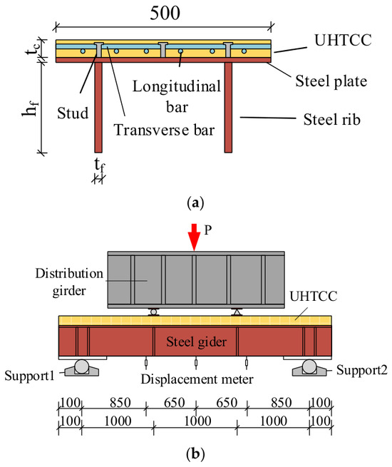
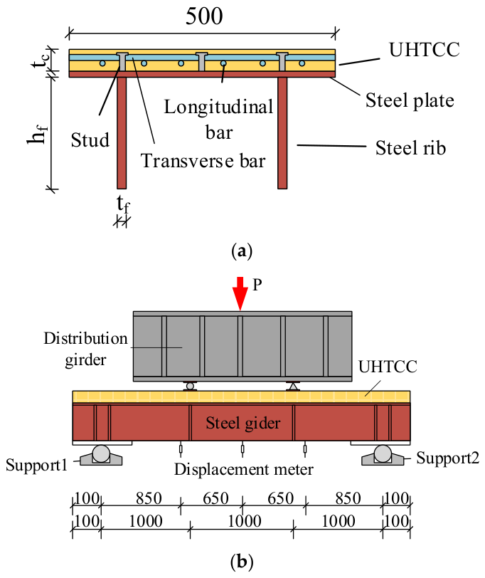
Figure 1a shows the cross-sectional configuration of the steel–UHTCC composite bridge deck designed in Ref. [11]. The upper part of the structure consists of a UHTCC overlay layer reinforced with a certain amount of longitudinal and transverse reinforcement, while the lower part is a steel structure composed of a steel deck and rib-type stiffeners. The upper and lower components are connected through welded shear studs to ensure effective shear transfer at the interface, enabling the two parts to act as an integral system and fully develop composite action under loading. The loading arrangement of the composite bridge is illustrated in Figure 1b. P, tc, and hf denote the applied load, UHTCC thickness, and steel rib height, respectively. The specimen has a span of 3 m and is subjected to a four-point loading configuration with third-point loading. At the supports of the composite bridge deck, end plates and stiffeners are provided to prevent local buckling of the steel plate due to stress concentration. A scripting approach was adopted in the general-purpose finite element software ABAQUS 2016 to develop the model, facilitating subsequent modifications and parametric analyses.
Figure 1.
Test program: (a) cross-section of the composite bridge deck (mm); (b) loading configuration of the composite bridge deck test (mm).
2.1. Model Parameters
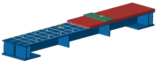
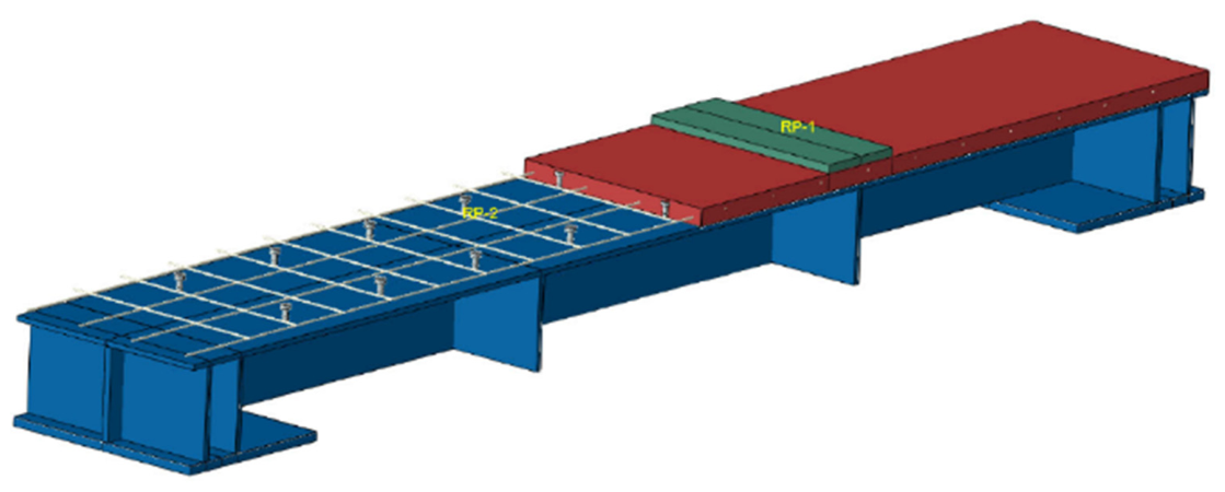
The model was established strictly in accordance with the specimen reported in Ref. [11], as shown in Figure 2. A strip with a width of 500 mm and a total length of 3200 mm was adopted, with an effective span of 3000 mm. The thickness of the UHTCC layer was taken as 40 mm, the thickness of the steel deck plate as 12 mm, and the thickness of the plate-type stiffeners as 16 mm, with a stiffener height of 200 mm. The number of stiffeners was set to two. Within the UHTCC layer, the longitudinal reinforcement consisted of four Φ10 bars spaced at 150 mm, while the transverse reinforcement consisted of 20 Φ10 bars at 150 mm spacing. The shear studs were arranged uniformly in two rows in the transverse direction and nine rows in the longitudinal direction. Short studs were adopted, with a height of 35 mm, a shank diameter of 13 mm, and a head diameter of 22 mm.
Figure 2.
Finite element model of the composite bridge deck.
2.2. Constitutive Models of Materials
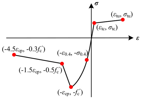
The constitutive model of UHTCC adopts the concrete damaged plasticity (CDP) model, which is a continuum damage mechanics model developed based on plasticity theory. The damage and plastic behavior of concrete under uniaxial tension and compression can be described through the CDP framework, which is capable of accurately simulating the mechanical response of UHTCC under static loading conditions [12]. The uniaxial tensile stress–strain relationship of UHTCC was simplified as a bilinear model according to the literature recommendations [13], while the uniaxial compressive stress–strain relationship was adopted from Ref. [14] and further calibrated based on the experimental data reported in Ref. [11]. The constitutive curves are shown in Figure 3, and the remaining parameters are listed in Table 1. The constitutive behaviors of the reinforcing steel, steel deck plate, and shear studs were all simplified as trilinear models. The specific parameter values were determined based on Ref. [11], as presented in Table 2.
Figure 3.
Plastic damage constitutive model for UHTCC.
Table 1.
UHTCC material parameters.
Table 2.
Material parameters of reinforcement, steel plate, and shear studs.
2.3. Element Selection and Mesh Discretization
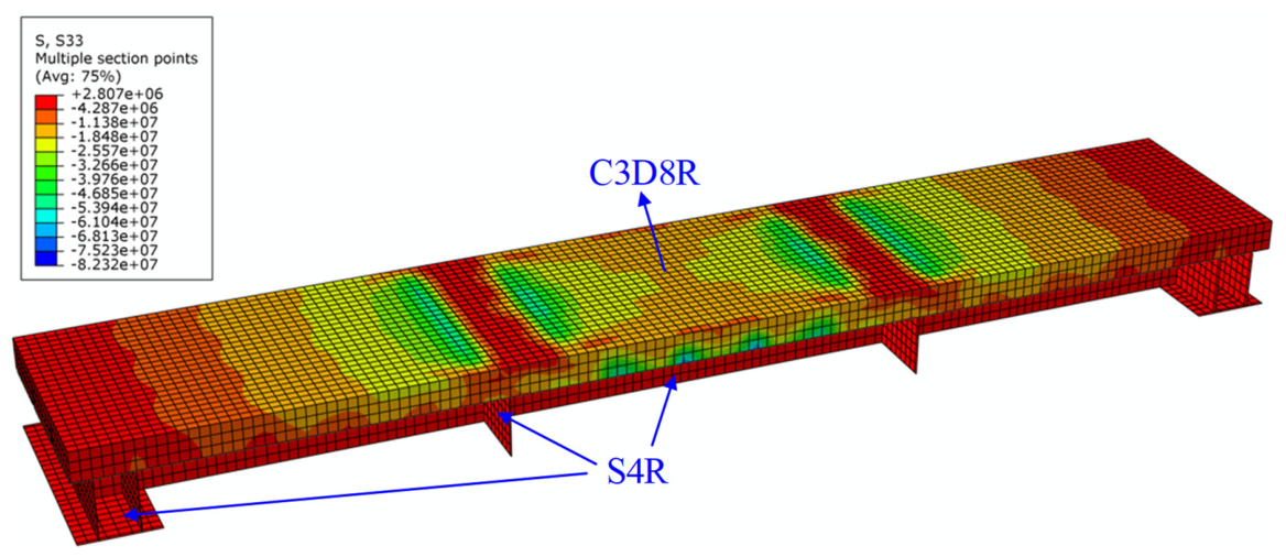
To ensure the accuracy of the simulation results, the UHTCC and shear studs were modeled using reduced-integration 8-node 3D solid elements (C3D8R), which are suitable for nonlinear analyses involving large deformation and plastic failure. The reinforcing steel was modeled using 2-node 3D truss elements (T3D2), which carry only axial forces without considering shear or bending effects, consistent with the mechanical behavior of reinforcement in reinforced concrete structures.
Considering that the width-to-thickness ratios of the lower steel components all exceed 10, satisfying the requirements for shell element formulation, the steel deck plate, longitudinal stiffeners, and transverse stiffeners were all modeled using 4-node quadrilateral reduced-integration shell elements with finite membrane strain (S4R) [14]. To balance computational accuracy and efficiency, a uniform mesh size of 25 mm was adopted for the entire model through grid sensitivity analysis to satisfy both accuracy and efficiency requirements.
2.4. Contact Interactions and Boundary Conditions
In the present model, the interaction relationships between different components were defined to accurately represent the behavior and stress state of the actual structure, as follows:
- (1)
- The interface between the steel deck plate and the UHTCC layer was modeled as a surface-to-surface contact with finite slip (Contact). The top surface of the steel deck, which has higher stiffness, was defined as the master surface, while the bottom surface of the UHTCC layer was defined as the slave surface. A friction coefficient of 0.2 was adopted [15], and a “hard contact” formulation was used in the normal direction to prevent interpenetration between the two surfaces.
- (2)
- Since shear studs are welded onto the steel deck plate in the actual structure, a tie constraint was defined between the studs and the steel deck plate. Meanwhile, as the studs are fully embedded in the UHTCC layer, an embedded interaction (Embedded) was assigned between the studs and the UHTCC. The same embedded constraint was also applied between the reinforcement and the UHTCC.
- (3)
- For the lower steel structural components, the steel deck plate and the longitudinal and transverse stiffeners act integrally in resisting loads; therefore, a merge operation was adopted to combine these parts into a single integrated component.
- (4)
- To simulate the actual loading condition, pin supports were applied at both ends of the model to establish a simply supported boundary condition.
2.5. Finite Element Model Validation
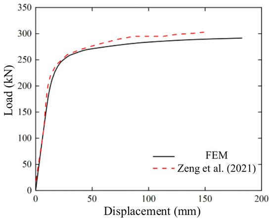
To verify the accuracy of the finite element model, the experimental results reported in Ref. [11] were compared with the corresponding load–displacement responses obtained from the present model. The comparison results are presented in Table 3 and Figure 4.
Table 3.
Comparison of characteristic loads between finite element results and experimental results.
Figure 4.
Comparison of load–displacement curves between experimental and finite element results [11].
Figure 4 compares the load–displacement curves of the steel–UHTCC composite bridge deck obtained from the full loading process between the finite element simulation and the experimental results reported in Ref. [11]. As can be observed, the mid-span load–displacement response predicted by the finite element model agrees well with the experimental curve, showing a similar overall trend throughout the loading process. In particular, the initial stiffness predicted by the model is almost identical to that of the experiment, with the two curves nearly overlapping in the elastic stage. Table 3 summarizes the characteristic values extracted from both the finite element analysis and the experimental results in Ref. [11]. It can be seen that the initial stiffness obtained from the finite element model is 16.57 kN/mm, while the ultimate load is 290 kN, with corresponding relative errors of 1% and 4%, respectively. These discrepancies are within an acceptable range for engineering applications. This indicates that the developed finite element model of the steel–UHTCC composite bridge deck is sufficiently accurate and can be reliably used for subsequent parametric analyses.
3. Parameter Study
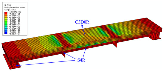
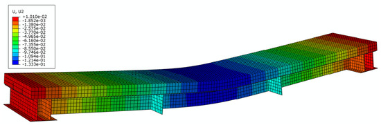
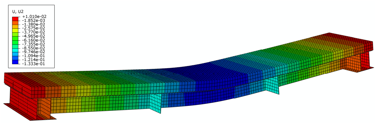
Using the validated finite element model, a parametric analysis was conducted to investigate the influence of different structural design parameters on the flexural performance of steel–UHTCC composite bridge decks. The design parameters considered include rib thickness, rib height, steel deck plate thickness, UHTCC layer thickness, and longitudinal reinforcement ratio. In the parametric analysis, to isolate the effect of each individual design parameter, only one parameter was varied at a time while all other parameters were kept consistent with those of the finite element model described in the previous section. The baseline configuration was defined as follows: rib thickness of 16 mm, rib height of 200 mm, steel deck plate thickness of 12 mm, UHTCC layer thickness of 40 mm, and longitudinal reinforcement arranged as 4Φ10@150. The cost of UHTCC was assumed to be 14,000 CNY/m3, while the cost of steel was taken as 70,000 CNY/m3. Figure 5 and Figure 6 illustrate the finite element stress contour maps and the corresponding deformation conditions, respectively.
Figure 5.
Longitudinal stress distribution on the bridge deck.
Figure 6.
Deformation pattern of the bridge deck.
3.1. Thickness of Rib
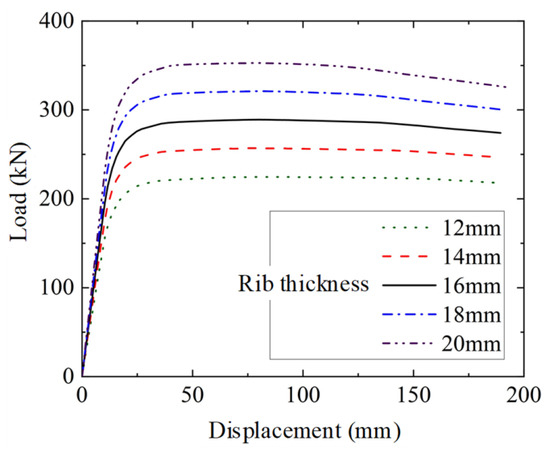
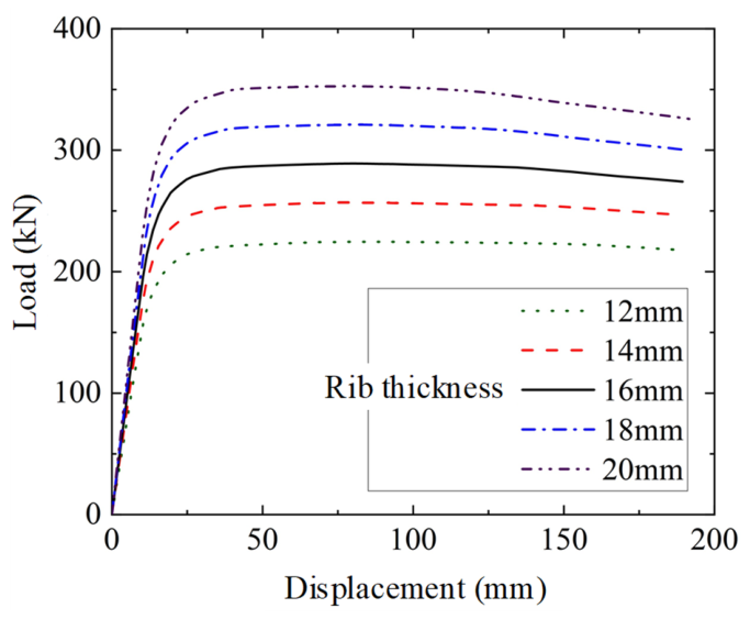
To investigate the influence of rib thickness on the stiffness and ultimate load-bearing capacity of steel–UHTCC composite bridge decks, a parametric study was conducted based on the finite element model established in the previous section. The rib height, steel deck plate thickness, UHTCC layer thickness, and longitudinal reinforcement ratio were kept unchanged, while the rib thickness was varied as 12, 14, 16, 18, and 20 mm, resulting in five comparative cases. The stiffness, ultimate load-bearing capacity, and cost of the composite bridge deck under different rib thicknesses are summarized in Table 4, and the corresponding finite element results are presented in Figure 7.
Table 4.
Results with varying rib thickness.
Figure 7.
Comparison of load–displacement curves with varying rib thickness.
As shown in Figure 7, both the initial stiffness and ultimate load-bearing capacity of the steel–UHTCC composite bridge deck increase gradually with increasing rib thickness. When the rib thickness increases from 12 mm to 20 mm, the initial stiffness increases from 13.27 kN/mm to 19.48 kN/mm, representing an increase of 47.0%. Meanwhile, the ultimate load-bearing capacity increases from 226 kN to 354 kN, corresponding to an increase of 56.6%. These results indicate that the flexural performance of the composite bridge deck is highly sensitive to rib thickness.
As shown in Table 4, both the cost-effectiveness of ultimate load-bearing capacity (η1) and the cost-effectiveness of initial stiffness (η2) increase with increasing rib thickness. This indicates that increasing rib thickness is an effective way to enhance both the initial stiffness and ultimate load-bearing capacity of the structure, and it represents a relatively cost-efficient design strategy.
3.2. Height of Rib
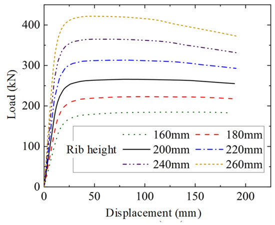
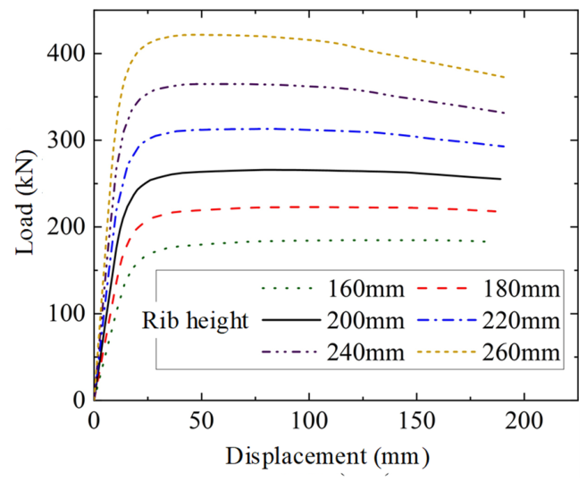
To investigate the influence of rib height on the stiffness and ultimate load-bearing capacity of steel–UHTCC composite bridge decks, six comparative cases were established with rib heights of 160, 180, 200, 220, 240, and 260 mm, respectively. The stiffness, ultimate load-bearing capacity, and cost of the composite bridge deck under different rib heights are summarized in Table 5, and the corresponding finite element results are presented in Figure 8.
Table 5.
Results with varying rib height.
Figure 8.
Comparison of load–displacement curves with varying rib height.
From the load–displacement curves shown in Figure 8, it can be observed that both the ultimate load-bearing capacity and the initial stiffness of the steel–UHTCC composite bridge deck increase significantly with increasing rib height, with a relatively large growth rate. Compared with the case of a rib height of 160 mm, the ultimate load-bearing capacities of the models with rib heights of 180, 200, 220, 240, and 260 mm increase by 20.7%, 44.0%, 69.6%, 97.3%, and 128.3%, respectively. The corresponding increases in initial stiffness are 33.8%, 73.4%, 120.0%, 173.7%, and 233.8%, respectively.
As shown in Table 5, both the cost-effectiveness of ultimate load-bearing capacity (η1) and that of initial stiffness (η2) increase substantially with increasing rib height. This indicates that increasing rib height can effectively enhance the longitudinal flexural performance of the composite bridge deck while also reducing the overall engineering cost.
3.3. Steel Deck Plate Thickness
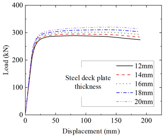
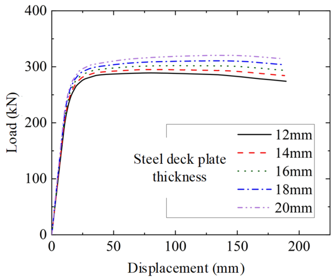
To investigate the influence of steel deck plate thickness on the stiffness and ultimate load-bearing capacity of steel–UHTCC composite bridge decks, five comparative cases were established with steel deck plate thicknesses of 12, 14, 16, 18, and 20 mm, respectively. The stiffness, ultimate load-bearing capacity, and cost of the composite bridge deck under different thicknesses are summarized in Table 6, and the corresponding finite element results are presented in Figure 9.
Table 6.
Results with varying steel deck plate thickness.
Figure 9.
Comparison of load–displacement curves with varying steel deck plate thickness.
As shown in Figure 9 and Table 6, increasing the steel deck plate thickness leads to a certain improvement in both the initial stiffness and ultimate load-bearing capacity of the steel–UHTCC composite bridge deck; however, the magnitude of this improvement is relatively limited. Compared with the case of a 12 mm steel deck plate, increasing the thickness to 20 mm results in increases of 14.2% in initial stiffness and 10.7% in ultimate load-bearing capacity. When the engineering cost is taken into account, it can be observed that both the cost-effectiveness of ultimate load-bearing capacity (η1) and the cost-effectiveness of initial stiffness (η2) decrease with increasing steel deck plate thickness. This indicates that enhancing the flexural performance of the composite bridge deck by increasing the steel deck thickness leads to a reduction in cost-effectiveness. In practical engineering applications, the selection of steel deck thickness is therefore mainly governed by structural and detailing requirements.
3.4. Thickness of UHTCC
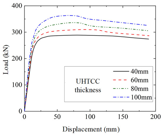
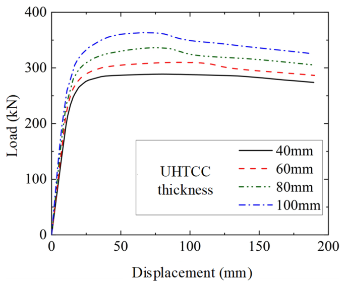
To investigate the influence of UHTCC layer thickness on the stiffness and ultimate load-bearing capacity of steel–UHTCC composite bridge decks, four comparative cases were established with UHTCC layer thicknesses of 40, 60, 80, and 100 mm, respectively. The stiffness, ultimate load-bearing capacity, and cost of the composite bridge deck under different UHTCC layer thicknesses are summarized in Table 7, and the corresponding finite element results are presented in Figure 10.
Table 7.
Results with varying UHTCC thickness.
Figure 10.
Comparison of load–displacement curves with varying UHTCC thickness.
From the load–displacement curves shown above, it can be observed that both the initial stiffness and ultimate load-bearing capacity of the steel–UHTCC composite bridge deck increase with increasing UHTCC layer thickness. Compared with the initial thickness of 40 mm, when the UHTCC layer thickness increases to 60, 80, and 100 mm, the ultimate load-bearing capacity increases by 7.3%, 16.5%, and 25.8%, respectively, while the corresponding increases in initial stiffness are 9.6%, 25.7%, and 44.3%, indicating a significant improvement in the longitudinal flexural performance of the structure.
However, for a fully UHTCC-overlaid bridge deck system, the material cost of UHTCC is relatively high. Therefore, increasing its thickness will substantially increase the overall engineering cost. As shown in Table 7, both the cost-effectiveness of ultimate load-bearing capacity (η1) and that of initial stiffness (η2) decrease with increasing UHTCC layer thickness. This indicates that enhancing the flexural performance of the composite bridge deck by increasing the UHTCC layer thickness results in low cost-effectiveness.
3.5. Longitudinal Reinforcement Ratio
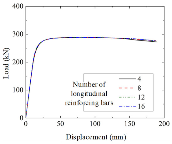
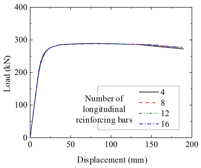
To investigate the influence of longitudinal reinforcement ratio on the stiffness and ultimate load-bearing capacity of steel–UHTCC composite bridge decks, four comparative cases were established with the number of longitudinal reinforcing bars set as 4, 8, 12, and 16, respectively. The finite element results are presented in Figure 11.
Figure 11.
Comparison of load–displacement curves with varying longitudinal reinforcement ratio.
As can be seen from the figure, when the number of longitudinal reinforcing bars increases from 4 to 16, the load–displacement curves obtained from the finite element model are nearly identical. This indicates that variations in the longitudinal reinforcement ratio have a negligible influence on the longitudinal positive-bending flexural performance of the steel–UHTCC composite bridge deck. The primary function of longitudinal reinforcement is to control cracking in the negative moment region of the deck slab [16]. For UHTCC materials with excellent crack-control capability, the amount of longitudinal reinforcement may be reduced, provided that relevant code-based detailing requirements are satisfied.
4. Theoretical Prediction
4.1. Calculation Formula for the Flexural Capacity of the Bridge Deck
Based on finite element models, the UHTCC slabs achieve full-section compression under sagging moment. Near the ultimate state, the bottom flange of the steel beam yields plastically, accompanied by crushing of the UHTCC slabs, while no interfacial slippage is observed between the steel components and the UHTCC slabs. Accordingly, the following assumptions are adopted to derive the formula for the ultimate flexural capacity of the bridge decks:
(1) A full shear connection is provided at the steel–UHTCC interface, and the plane-section assumption holds for the sectional strain distribution;
(2) After cracking, the tensile zone of UHTCC remains active and exhibits tension-hardening behavior until the ultimate tensile strength σtu is reached;
(3) At failure, the full cross-section becomes fully plastic, with the stress distributions in the UHTCC and steel beam idealized as rectangular.
Equation (1) shows the relationship that the compressive and tensile stresses in the UHTCC slabs and steel members must satisfy, as dictated by the axial force equilibrium condition.
Here, the symbols Ncc and Ncs stand for the compressive forces in the UHTCC and steel components and Ntc and Nts for the tensile forces, respectively. Therefore, the expression for the ultimate flexural resistance can be derived from Ref. [10] as follows:
Here, σtc and fsy are the tensile strengths of UHTCC and steel; nr, tr, and hr are the number, thickness, and height of the plate ribs; and ts is the steel deck thickness; η denotes the reduction coefficient; parameter b is found to be 0.124 by test results; tc is the thickness of UHTCC; σtc, εtc, and εtu are the tensile first-cracking strength, tensile first-cracking strain, and ultimate tensile strain of UHTCC, respectively.
4.2. Comparison Between Theoretical and Simulated Results
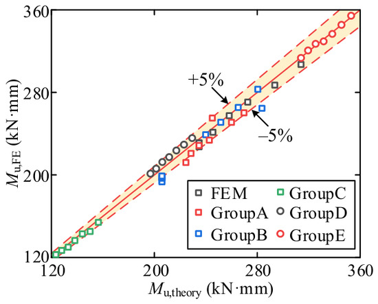
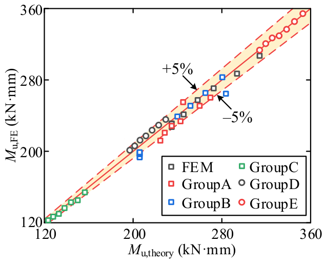
Figure 12 shows a comparison of the flexural capacity values predicted by the theoretical formula versus those calculated from FE simulations. To facilitate comparison, the parameter sets examined in the preceding section are labeled as follows: Group A (rib thickness), Group B (rib height), Group C (steel deck plate thickness), Group D (UHTCC thickness), and Group E (longitudinal reinforcement ratio). Furthermore, to better demonstrate the theoretical analysis’s applicability, each group’s FE model count is raised by a certain proportion to facilitate theoretical error comparisons. It can be seen from Figure 12 that the theoretical formula provides good estimates of the flexural capacity for steel-UHTCC bridge decks, with differences between the theoretical and FE results lying within ±5%.
Figure 12.
Comparison between theoretical predictions and FE simulation results.
5. Conclusions
In this study, a refined finite element model of the steel–UHTCC composite bridge deck was developed based on existing experimental results. The discrepancy between the numerical and experimental results was within 5%, confirming the validity of the proposed model. Subsequently, a parametric analysis was conducted on key design variables of the composite bridge deck, and the main conclusions are summarized as follows:
(1) Increasing rib thickness and rib height can significantly enhance the longitudinal flexural performance of the composite bridge deck, with relatively high cost-effectiveness.
(2) Increasing the steel deck plate thickness and UHTCC layer thickness can improve the longitudinal flexural performance to some extent; however, their cost-effectiveness is relatively low.
(3) The longitudinal reinforcement ratio has a negligible influence on the longitudinal load-bearing capacity and stiffness of the composite bridge deck.
It is acknowledged that in composite structures, the distribution of forces and stresses during the service phase can be influenced by load history (e.g., girder construction technology) and rheological phenomena in concrete. These factors are not explicitly considered in the present analysis due to its specific scope but should be addressed in future studies.
Author Contributions
Conceptualization, M.-L.M. and J.-Z.T.; methodology, J.-L.C.; software, G.-W.X.; validation, C.-D.Y.; formal analysis, C.-D.Y.; investigation, B.W.; resources, B.W.; data curation, B.W.; writing—original draft preparation, J.-L.C.; writing—review and editing, J.-L.C.; visualization, J.-Z.T.; supervision, J.-Z.T.; project administration, Q.-H.L.; funding acquisition, Q.-H.L. All authors have read and agreed to the published version of the manuscript.
Funding
This study has been supported by the CSCEC Technology R&D Program (Grant no. CSCEC-2025-Z-25) and the CCEED Technology R&D Program (Grant no. 2024-4-08).
Data Availability Statement
The original contributions presented in this study are included in the article. Further inquiries can be directed to the corresponding author.
Conflicts of Interest
Authors Ming-Lei Ma, Guo-Wen Xu and Biao Wu were employed by the company China Construction Eighth Engineering Division Co., Ltd. The remaining authors declare that the research was conducted in the absence of any commercial or financial relationships that could be construed as a potential conflict of interest.
References
- Xiang, Y.; Zhu, S.; Zhao, Y. Research progress on rapid construction bridges. China J. Highw. Transp. 2018, 31, 1–27. [Google Scholar]
- Xiao, L.; Wei, X.; Wen, Z.; Li, G. Research progress on steel–concrete composite bridges in 2019. J. Civ. Environ. Eng. (Chin. Engl.) 2020, 42, 168–182. [Google Scholar]
- Zhang, Q.; Bu, Y.; Li, Q. Review on fatigue problems of orthotropic steel bridge deck. China J. Highw. Transp. 2017, 30, 14–30. [Google Scholar]
- Zhang, Y.; Cai, S.; Zhu, Y.; Fan, L.; Shao, X. Flexural responses of steel–UHPC composite beams under hogging moment. Eng. Struct. 2020, 206, 110134. [Google Scholar] [CrossRef] [Scilit]
- Luo, Z.; Tan, C.; Cao, J.; Liu, K.; Luo, S.; An, J.; Zhao, H.; Shao, X.; Yi, D. Orthotropic steel deck reinforcement technique for super-long span bridges with thin dense-reinforced UHPC layers. Eng. Struct. 2025, 308, 121444. [Google Scholar] [CrossRef] [Scilit]
- Luo, Z.; Zhao, H.; Qiao, D.; Zhang, Y.; An, J.; Tan, C.; Liang, L.; Liu, A.; Shao, X. Shear behavior on PBL shear connector with a relatively thin perforated steel plate in steel-UHPC composite bridge deck system. Eng. Struct. 2024, 316, 118583. [Google Scholar] [CrossRef] [Scilit]
- Li, P.; Shao, X.; Cao, J.; Kong, L. Flexural cracking behavior and parametric analysis of steel-UHPC composite decks without longitudinal ribs. Eng. Struct. 2026, 346, 121632. [Google Scholar] [CrossRef] [Scilit]
- Wu, J. Study on Basic Mechanical Behavior of Orthotropic Steel Deck–ECC Composite Pavement Structure. Master’s Thesis, Shandong University, Jinan, China, 2021. [Google Scholar]
- Li, Q.; Xu, S. Research progress on basic properties and structural applications of ultra-high toughness cement-based composites. Eng. Mech. 2009, 26, 23–67. [Google Scholar]
- Tong, J.; Chen, Y.; Li, Q.; Xu, S.; Zeng, T.; Gao, W. Experimental study on flexural performance of steel-UHTCC composite bridge decks considering different shear connection degrees. Eng. Struct. 2023, 281, 115738. [Google Scholar] [CrossRef] [Scilit]
- Zeng, T. Study on Flexural Bearing Capacity of Steel–UHTCC Composite Bridge Decks. Master’s Thesis, Zhejiang University, Hangzhou, China, 2021. [Google Scholar]
- Nie, J.; Wang, Y. Comparative study of concrete constitutive models in ABAQUS for simulating structural static behavior. Eng. Mech. 2013, 30, 59–67. [Google Scholar]
- Li, V.C.; Wang, S.; Wu, C. Tensile strain-hardening behavior of polyvinyl alcohol engineered cementitious composite (PVA-ECC). ACI Mater. J. 2001, 98, 483–492. [Google Scholar] [CrossRef] [Scilit] [PubMed]
- Shao, X.; Zhang, H.; Li, J.; Cao, J.; Gan, Y. Shear performance of short studs in steel–ultra-thin UHPC lightweight composite bridge decks. China Civ. Eng. J. 2020, 53, 39–51. [Google Scholar]
- Fan, J.; Gou, S.; Ding, R.; Zhang, J.; Shi, Z. Experimental and analytical research on the flexural behaviour of steel–ECC composite beams under negative bending moments. Eng. Struct. 2020, 210, 110309. [Google Scholar] [CrossRef] [Scilit]
- Wang, Z.; Nie, X.; Fan, J.; Lu, X.Y.; Ding, R. Experimental and numerical investigation of the interfacial properties of non-steam-cured UHPC–steel composite beams. Constr. Build. Mater. 2019, 195, 323–339. [Google Scholar] [CrossRef] [Scilit]

Disclaimer/Publisher’s Note: The statements, opinions and data contained in all publications are solely those of the individual author(s) and contributor(s) and not of MDPI and/or the editor(s). MDPI and/or the editor(s) disclaim responsibility for any injury to people or property resulting from any ideas, methods, instructions or products referred to in the content. |
© 2026 by the authors. Licensee MDPI, Basel, Switzerland. This article is an open access article distributed under the terms and conditions of the Creative Commons Attribution (CC BY) license.