


Abstract
Monitor-roof designs are widely used in buildings to enhance natural ventilation while protecting interior spaces from rain penetration. However, the ventilation performance of rain-shield monitor roofs can be significantly influenced by their geometric configuration and the interaction between wind-driven and buoyancy-driven airflow. In this study, computational fluid dynamics (CFD) simulations were conducted to investigate the ventilation performance of rain-shield monitor roofs under hybrid natural ventilation conditions. The effects of key geometric parameters, including the outlet height (Lz) and lateral spacing (Ly), were examined under different approaching wind conditions. The results indicate that ventilation performance is governed by the combined influence of wind-driven and buoyancy-driven mechanisms. Among the investigated configurations, an intermediate outlet height of approximately Lz ≈ 0.6 m generally provides favorable ventilation performance, while a lateral spacing Ly in the range of 0.6–0.8 m maintains effective airflow passage without excessive flow resistance. The findings provide quantitative guidance for the design of rain-shield monitor-roof ventilation systems in buildings operating under hybrid natural ventilation conditions.
1. Introduction
Natural ventilation remains an important passive strategy for improving indoor environmental quality and reducing mechanical cooling demand in buildings. In large-span buildings such as factories, gymnasiums, exhibition halls, and agricultural facilities, roof-level openings are often adopted to release accumulated warm air and enhance air exchange through wind-induced and buoyancy-induced driving forces. Because these two driving mechanisms may reinforce, weaken, or redirect each other depending on outdoor wind conditions and internal thermal loads, ventilation behavior is often governed by the coupled interaction between building geometry and the surrounding airflow field [1,2,3].
Monitor roofs, as ridge vents at smaller scales, are commonly used as building ventilation elements. By introducing openings near the roof ridge or upper roof zone, these systems can promote upward exhaust flow and improve ventilation through the combined effects of stack pressure and wind pressure. In cold and temperate climates, similar roof-ventilation concepts are frequently used to control moisture accumulation in attics, whereas in subtropical regions they are often adopted to remove solar heat gain and improve thermal conditions beneath the roof [4,5]. Related studies have also examined roof-ventilation systems in greenhouse and other large-span building applications [6,7].
For industrial and large-span buildings, the aerodynamic behavior of roof openings has attracted increasing attention because roof-vent geometry can affect not only the ventilation rate but also indoor air distribution, pollutant removal, and the integration of other rooftop systems. Wang et al. [8] conducted a numerical study on pollutant transport between neighboring industrial workshops, demonstrating that ventilation behavior and contaminant dispersion are highly affected by the coupled effects of external wind flow and buoyancy induced by indoor heat sources. Cao et al. [9] examined the effects of roof vent arrangement and roof configuration on natural ventilation performance and rooftop photovoltaic installation in industrial workshops, demonstrating the importance of roof-opening design in balancing ventilation performance and other building functions. Ho et al. [10] developed a ridge-vent-integrated cool roof system for tropical climatic conditions and assessed its thermal regulation and energy-saving potential using both CFD analysis and on-site measurements. These studies indicate that roof-level ventilation design should be considered as an integrated architectural and environmental-control issue rather than as a simple opening-area problem.
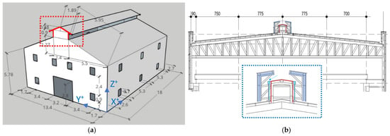
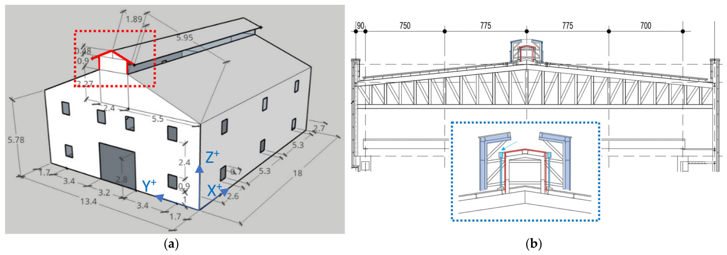
In the Taiwanese building context considered in previous monitor-roof studies (as indicated by the red dashed area in Figure 1a [11,12,13], roof-level openings, are commonly adopted to enhance ventilation beneath the roof. However, in practical applications, such openings are also exposed to wind-driven rain. To reduce rainwater intrusion while maintaining natural ventilation, auxiliary rain-shield elements are sometimes installed above the monitor-roof opening. This modification changes the original roof vent into a constrained airflow passage, in which the shielding elements may simultaneously provide rain protection, modify the effective outlet height, alter flow contraction, and interact with the external roof shear layer. Therefore, the ventilation performance of a rain-shield monitor roof cannot be evaluated solely from the nominal opening size; it must be interpreted in relation to the three-dimensional airflow induced by wind direction, wind speed, buoyancy, and local geometric configuration.
Figure 1.
Configuration of the original monitor roof (red outline) and the modified monitor roof with a rain shelter (blue outline) (unit: m). (a) A monitor roof design. Reproduced from Ref. [11] under the CC BY license. (b) Rain shelter.
Previous studies by the authors and others have provided useful information on the ventilation performance of conventional monitor roofs and related roof-vent systems. Chen et al. [11] investigated ridge-vent ventilation driven by buoyancy effects and reported that roof height plays a significant role in controlling airflow behavior under thermally induced ventilation conditions. Lin et al. [12] further investigated the effect of outdoor wind on the hybrid natural ventilation performance of monitor roofs and showed that wind direction and wind speed can significantly alter the ventilation behavior. In addition, Win et al. [13] assessed how adding a rain shelter, indicated by the blue dashed outline in Figure 1b, affects the ventilation performance of a monitor roof.
Although the above studies provide an important foundation for understanding monitor-roof ventilation, the present study differs from Refs. [11,12,13] in both scope and scientific objective. These previous studies clarified the basic ventilation behavior of monitor roofs and the influence of rain-shelter installation. However, they did not systematically address how the geometric control role of the rain-shield structure changes when the approaching wind direction varies. The present study, therefore, goes beyond previous monitor-roof ventilation studies by focusing on the wind-direction-dependent geometric control mechanism of rain-shield monitor roofs. Rather than treating the rain shield as a fixed add-on component or evaluating only the overall change in ventilation rate, this study examines how two key geometric parameters, the vertical clearance (Lz) and lateral spacing (Ly), influence ventilation performance under normal, oblique, and lateral wind incidence.
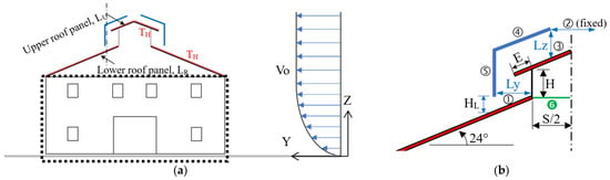
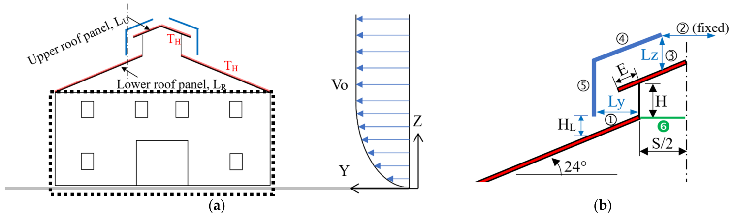
The term “rain-shield monitor roof” is used here to describe a monitor-roof ventilation configuration equipped with protective shielding elements that reduce rain penetration while permitting airflow through the roof opening. Using CFD simulations, this study investigates how two key geometric parameters—the vertical distance between the rain-shield top and the upper monitor roof panel, denoted as Lz (Figure 2b), and the lateral distance between the rain-shield side plates and the monitor-roof side walls, denoted as Ly (Figure 2b), affect ventilation performance under different outdoor wind speeds and wind-approaching angles of 0°, 45°, and 90°.
Figure 2.
Physical model employed in this study (not to scale; unit: m). (a) Monitor roof with a rain shelter and the space below. (b) Design parameters.
Rather than treating the problem as a simple search for a single optimal geometry, this study aims to clarify how the controlling mechanism of ventilation changes with wind direction. The analysis distinguishes between geometry-dominated, geometry–flow interaction, and momentum-limited ventilation regimes, and translates these mechanisms into design implications for early-stage building design. By doing so, the study provides geometry-based guidance for rain-shield monitor roofs in practical building environments where wind direction is uncertain and ventilation performance must remain robust under varying outdoor conditions.
2. Research Method
2.1. Research Object
To improve the clarity of the physical configuration, the proposed rain-shield monitor-roof system is first illustrated as a practical architectural solution (Figure 1b). In this configuration, an additional inclined shielding panel and side plates are installed above the original monitor-roof opening to reduce direct rain penetration while maintaining a roof-level ventilation path. After presenting this detailed configuration, a simplified physical model is defined for the CFD simulations (Figure 2). The simplified model preserves the major airflow passages and geometric control parameters of the practical solution, while omitting secondary construction details that are not the focus of the present parametric analysis.
Monitor roofs can be applied to a wide range of spaces, such as gymnasiums, exhibition halls, factories, greenhouses, etc. Consequently, the spatial configuration and opening characteristics of the space beneath the roof (indicated by the dashed box in Figure 2a) can vary considerably. The objective of this study is to investigate the effects of installing a rain shelter on a monitor roof (hereafter referred to as a modified monitor roof) on its hybrid natural ventilation performance, involving both buoyancy-driven and wind-driven ventilation. Therefore, in the physical modeling process, the spatial configuration beneath the roof is fixed, and an industrial building is adopted as the representative application scenario.
In typical industrial building design, the size of the factory space, including its floor area and height, is generally established before the roof configuration and ventilation scheme are determined. Based on this design practice, the modified monitor roof considered in this study is assumed to have the same plan dimensions as the factory space below. As shown in Figure 1, the roof spans 18 m and 13.4 m in the X+ and Y+ directions, respectively. The geometric parameters and model settings adopted in the CFD simulations are summarized in Table 1.
Table 1.
Geometric parameters of the rain-shield monitor-roof model.
In the present model, doors and windows of the industrial building were assumed to be open to allow outdoor air to enter the building, forming a natural ventilation path toward the monitor-roof outlet or external wall openings. The roof outlet was assumed to be a free opening without insect screens, which is consistent with common installations in industrial buildings.
As shown in Figure 2b, the baseline monitor roof was characterized by three main geometric descriptors: width (S) of the opening, roof height (H), and eave depth (E). In engineering practices, these geometric dimensions typically range from approximately S = 1.2–3.0 m, H = 0.3–1.2 m, and E = 0–0.6 m. In this study, a representative baseline configuration was selected with S = 1.2 m, H = 1.2 m, and E = 0 m. The rain shield was subsequently formed by adding an auxiliary shielding element above the monitor roof, as indicated by the blue components in Figure 1b and Figure 2.
As shown in Figure 2b, the rain-shield configuration was described by two variable clearances and two fixed geometric settings. The lateral spacing Ly represents the distance between the rain-shield side plates and the inner monitor-roof walls, whereas the vertical clearance Lz represents the distance between the rain shield top and the upper monitor-roof panel. In the present analysis, the outlet width of the rain shield was fixed at 1.0 m, and the side opening (HL) was fixed at 0.6 m. The inclined rain-shield panel was designed to follow the same slope as the monitor roof, allowing its panel length to be determined geometrically.
The dimensions ➀ and ➂ follow the definitions of vertical and horizontal distances commonly used in building engineering practice, rather than the channel width typically adopted in heat transfer studies. The outlet width ➁ should not be excessively large, in order to prevent rainwater splashing into the monitor roof, nor too small, so as to avoid restricting airflow. In engineering practice, a value of 1 m is commonly adopted for ➁. Based on these considerations, the present study selects the following two key geometric parameters (Ly and Lz) for analysis, as illustrated in Figure 2b.
The present parametric analysis focused on two rain-shield clearances, Ly and Lz. The lateral spacing Ly was assigned values of 0.6, 0.8, and 1.0 m to evaluate its influence on the available side-flow passage and airflow guidance. The vertical clearance Lz was assigned values of 0.4, 0.6, and 0.8 m to examine how the outlet position affects the coupling between the monitor-roof opening and the external wind field. These parameter levels were selected as representative dimensions for industrial rain-shield monitor-roof configurations and were used to clarify the effects of geometric variation on ventilation performance.
2.2. Numerical Methods
Computational fluid dynamics (CFD) simulations were carried out to analyze the airflow and temperature distributions in the present problem. The commercial CFD package PHOENICS (2019 version) was used for the numerical calculations, where the governing equations were discretized using the finite volume approach with the boundary conditions and parameter settings specified in Table 2. The simulations were performed by solving the three-dimensional incompressible Navier–Stokes equations together with the steady-state convection–diffusion equation, with turbulence represented using the LVEL model. Details are available in reference [14]. The reliability of the present numerical framework, including the turbulence treatment, was verified through comparison with experiments conducted by Chen et al. [11]. The mathematical formulations of these governing equations are described in detail in the PHOENICS user manual [14]; therefore, they are not presented again in this paper.
Table 2.
Numerical settings and boundary conditions used in the CFD simulations.
It should be noted that hybrid natural ventilation may involve unsteady phenomena such as vortex shedding, intermittent flow exchange, and oscillatory roof-level shear layers. Therefore, the ventilation rates reported in this study should be interpreted as engineering-level, quasi-steady indicators rather than instantaneous flow responses. The buoyancy effect was modeled using the Boussinesq approximation. The approaching wind profile was specified using a power-law velocity profile. Near-wall airflow and thermal gradients were treated using the general wall-function scheme available in PHOENICS. The simulations were regarded as converged when the normalized residuals of the solved variables decreased below 10−3.
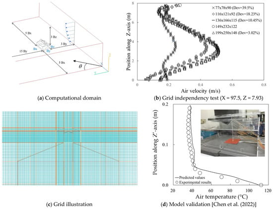
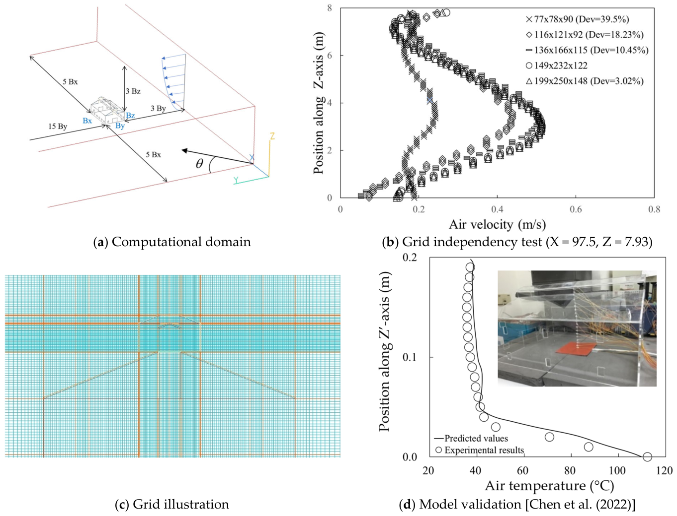
The size of the computational domain adopted in this study is shown in Figure 3a and was determined in accordance with the guidelines recommended by Franke et al. [15], Tominaga et al. [16], and Blocken [17]. For normal wind incidence, the location where the wind enters the computational domain (i.e., the upstream boundary) was set at the plane Y = 0. The distance between the model building and the upstream boundary was set to 3 By to reduce unnecessary inlet wind gradients [17], while the distances to the lateral boundaries and the downstream boundary were set to 5 Bx and 15 By, respectively. When the wind approached laterally (θ = 90°), the inflow boundary was specified at the plane X = 0. The corresponding distances between the model building and the upstream, side, and downstream boundaries were assigned as 3 Bx, 5 By, and 15 Bx, respectively. For the oblique wind case with an approaching angle of 45°, inflow boundaries were assigned to both the X = 0 and Y = 0 planes. The spacing between the building model and the domain limits was based on the largest values used in the preceding cases. Specifically, the upstream distances from the X = 0 and Y = 0 planes were set to 3 Bx and 3 By, respectively, whereas the downstream extensions were specified as 15 Bx and 15 By. For all simulation cases, the vertical clearance from the building model to the upper domain boundary was maintained at 3 Bz.
Figure 3.
Definition of the computational domain (a), grid independence tests (b), grid illustration (c), and validation of the numerical model (d). Panel (d) is adapted from Ref. [11] under the CC BY license.
The computational domain was adjusted according to the approaching wind direction to ensure sufficient upstream development and downstream recovery of the external airflow. For the 0° case, the inlet boundary was assigned to the Y = 0 plane. The upstream distance was set to 3 By, and the lateral and downstream clearances were set to 5 Bx and 15 By, respectively, following the domain-size recommendation for building aerodynamics [17]. For the 90° case, the inlet plane was shifted to X = 0, with corresponding upstream, lateral, and downstream distances of 3 Bx, 5 By, and 15 Bx, respectively. For the oblique 45° case, inflow was prescribed at both the X = 0 and Y = 0 planes. The domain extents were then determined using the larger clearances required by the two principal wind directions, with 3 Bx and 3 By upstream distances and 15 Bx and 15 By downstream distances in the X- and Y-directions, respectively. For all wind directions, the vertical clearance between the building and the top boundary was maintained at 3 Bz.
The external boundaries were treated as open boundaries using Neumann conditions, except at the prescribed inflow plane and the ground surface (Z = 0). This setting was adopted to reduce artificial confinement of the outdoor airflow around the building model. The inlet wind speed was prescribed using a power-law profile with an exponent of 0.143 to represent open-terrain conditions, with the reference velocity Vo defined at a height of 10 m above ground level. For the thermal boundary conditions, the roof surfaces exposed to solar heating were assigned an equivalent surface temperature TH, whereas the ambient air temperature To was maintained at 28 °C. All remaining building envelope surfaces, together with the ground plane, were assumed to be adiabatic. Radiation exchange and heat conduction through the envelope were neglected in order to isolate the airflow response associated with wind-driven and buoyancy-driven ventilation.
The wind approach angles (, shown in Figure 3a) of 0°, 45°, and 90° were selected as representative wind directions relative to the building orientation. Considering the geometric symmetry of the building model, these angles capture the principal airflow patterns associated with wind parallel, perpendicular, and oblique to the monitor-roof ridge.
A grid-independence assessment was performed to ensure that the predicted airflow field was not unduly affected by mesh resolution. Particular attention was given to regions near solid surfaces, the building interior, and the roof-opening passage, where velocity gradients were expected to be relatively large. Several mesh systems were tested, and the resulting velocity profiles along the Y-direction, corresponding to the opening-width direction S, were compared to determine an appropriate balance between numerical stability and computational cost. The deviation percentages between velocity profiles were evaluated to assess mesh sensitivity and to identify a suitable grid system for the present simulations. The velocity sampling locations were set at X = 99 m, Y = 45.5 m, and Z = 0–7.8 m. The grid independence test results are presented in Figure 3b. Based on this assessment, a computational mesh consisting of approximately 149 × 232 × 122 cells, corresponding to a total of 4,217,296 cells, was adopted for all numerical simulations in this study, as illustrated in Figure 3c.
To validate the reliability of the numerical model adopted in the present study, a benchmark case reported in the experimental study of Chen et al. [11] was reproduced numerically. The same geometric configuration and boundary conditions were implemented in the present CFD model to ensure a consistent basis for comparison. The predicted profiles were then compared with the corresponding experimental measurements reported in that study.
As shown in Figure 3d, the numerical predictions exhibit trends that are consistent with the experimental data. The predicted airflow temperatures along the measurement line follow the same distribution pattern as the experimental results, indicating that the present CFD model is capable of capturing the essential flow characteristics of monitor-roof ventilation. The mean deviation between the numerical predictions and the experimental measurements is 8.8%, which falls within an acceptable range for building-scale natural ventilation simulations [16,17]. It should be noted that this validation case was used solely to confirm the reliability of the numerical approach. After the numerical model was validated, it was applied to investigate the effects of different geometric design parameters of rain-shield monitor roofs under various wind conditions, which were not examined in Refs. [11,13].
2.3. Data Deduction
The ventilation rate of the (modified) monitor roof is expressed in cubic meters per second (m3/s), hereafter referred to as CMS, and can be calculated as
where denotes the outward velocity across the local vent-opening element (i,j), and is the corresponding elemental area. The ventilation rate was evaluated at opening ❻ in Figure 2b, which has a width (S) of 1.2 m and a length of 18 m.
3. Results and Discussion
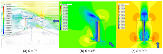
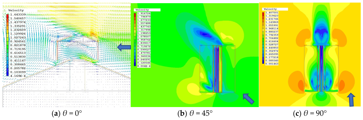
Figure 4 presents representative airflow patterns around the rain-shield monitor roof at Vo = 1 m/s for the three investigated wind-approaching directions. Figure 4a (θ = 0°) is shown using velocity vectors to clarify the local airflow direction and recirculation near the roof-opening region, whereas Figure 4b (45°) and Figure 4c (90°) are shown using velocity contours to better illustrate the spatial distribution of high- and low-velocity regions. The figure shows that the wind impact changes markedly with the approaching angle. Under (θ = 0°), the airflow interacts more directly with the roof opening and rain-shield passage, resulting in a geometry-sensitive flow structure. Under (θ = 45°), the oblique incoming flow produces an asymmetric velocity distribution and a stronger interaction between the local geometry and the external roof-level flow field. Under (θ = 90°), the airflow mainly sweeps laterally across the monitor-roof system, reducing the direct wind-induced momentum available for vertical exhaust. This graphical comparison supports the wind-direction-dependent interpretation of the ventilation mechanisms discussed in Section 3.1, Section 3.2 and Section 3.3.
Figure 4.
Representative airflow patterns around the rain-shield monitor roof at (Vo = 1) m/s for wind-approaching angles of (a) (0°) (vertical cross-section view), (b) (45°) (horizontal at Z = 8.3 m, bottom of the monitor roof), and (c) (90°) (horizontal). Blue arrows indicate the approaching wind direction.
3.1. Wind Approaching Angle = 0°
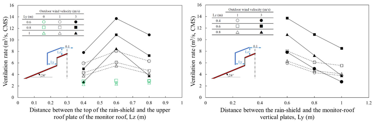
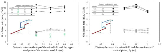
When the wind approached the building at 0°, the rain-shield monitor roof showed a ventilation response (2.3–2.9 CMS) that was primarily controlled by outlet geometry. Figure 5 indicates that the ventilation rate was highly sensitive to the vertical clearance Lz and the lateral spacing Ly, implying that both the outlet position and the side-flow passage substantially affected airflow development. Under normal wind incidence, the approaching wind can impose an effective pressure difference across the roof-opening region, allowing geometric changes in the rain-shield structure to be directly reflected in the ventilation rate.
Figure 5.
Effects of the vertical clearance Lz and lateral spacing Ly on the ventilation rate (CMS, m3/s) of the modified monitor roof under different outdoor wind speeds for the 0° wind-approaching case. The (left) and (right) panels correspond to Lz and Ly, respectively.
As shown in Figure 5 (left), for the parameter Lz, the ventilation rate exhibits a non-monotonic variation with increasing Lz under wind-driven conditions, with a pronounced peak observed at intermediate Lz values. Relative sensitivity of the ventilation rate to Lz is 226% ((max. − min.)/min. among the tested Lz configurations). When Lz increases from smaller values, the increased outlet height helps reduce flow separation near the outlet and enhances the induction of airflow within the tower by the external wind field, thereby increasing the ventilation rate. However, as Lz is further increased to larger values, the ventilation rate decreases, indicating that an excessively large outlet height weakens the effective pressure difference and flow acceleration, leading to diminished geometric amplification effects. This trend is more pronounced at higher wind speeds, suggesting that Lz primarily influences ventilation performance by regulating the outlet induction mechanism and the efficiency with which external wind pressure is converted into ventilation momentum.
The ventilation rates under the buoyancy condition (Vo = 0 m/s) ranged from approximately 2.3 to 2.9 CMS (marked in greed n Figure 5 (left)) among the investigated configurations. These values were lower than those obtained under wind-driven conditions.
In contrast, the effect of Ly on the ventilation rate exhibits a more consistent monotonic trend, as shown in Figure 5 (right). Under the same wind speed and Lz conditions, the ventilation rate decreases with increasing Ly, indicating that the lateral spacing is a key geometric parameter controlling flow contraction and momentum concentration within the tower. Smaller Ly values promote the formation of an accelerated internal flow passage, enabling external wind pressure to be more effectively converted into ventilation momentum. As Ly increases, the confinement of the flow passage weakens, momentum dissipation intensifies, and the ventilation rate is consequently reduced. This trend remains consistent across different Lz conditions, demonstrating that Ly serves as a robust geometric control parameter under normal wind incidence.
Overall, the simulation results suggest that these results indicate that under normal wind incidence, the ventilation performance of the rain-shield monitor roof is primarily governed by geometric configuration. Specifically, Lz determines the effectiveness of outlet induction and interaction with the external wind field and exhibits an optimal range, whereas Ly governs momentum development within the internal flow passage and exerts a stable, monotonic influence on the ventilation rate. Although Lz and Ly act on the outlet region and the internal flow passage, respectively, they jointly determine the maximum achievable ventilation performance under normal wind conditions.
Without the outdoor wind (Vo = 0), the airflow is driven purely by buoyancy induced by the temperature difference between the heated roof and the ambient air. Under this condition, the ventilation performance is mainly governed by the stack effect. The outlet height (Lz) influences the effective vertical distance associated with the buoyancy-driven pressure difference, while the lateral spacing (Ly) affects the flow resistance within the ventilation path.
3.2. Wind Approaching Angle = 45°
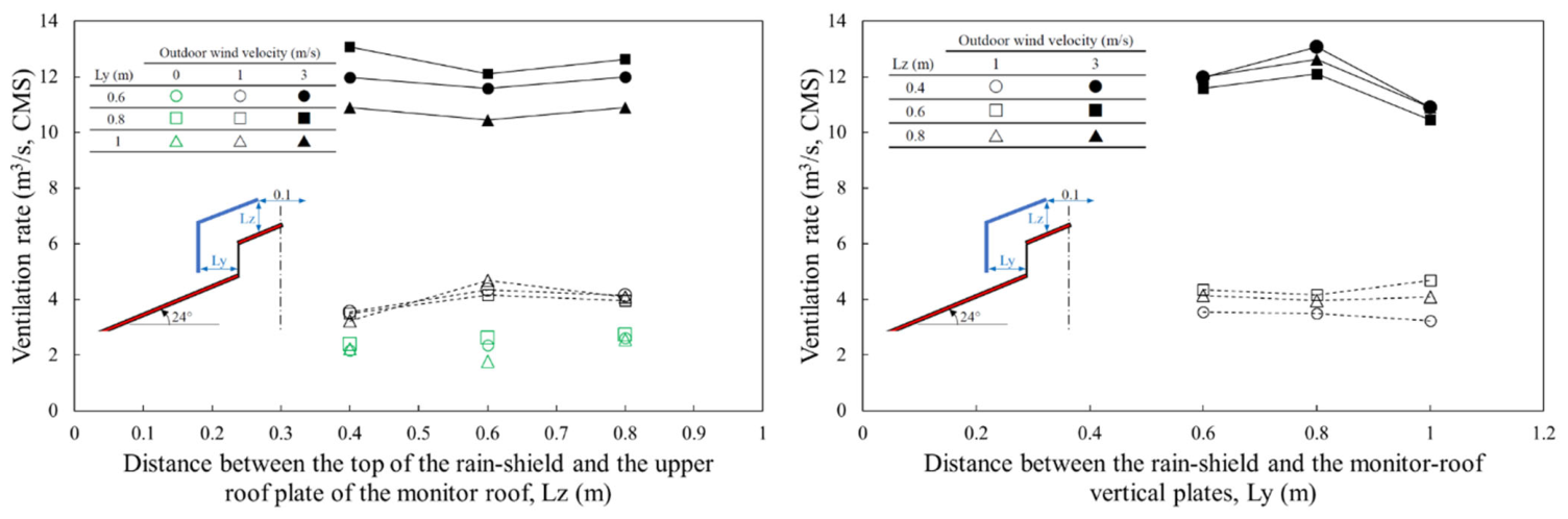
Under oblique wind conditions (wind approaching angle = 45°), the ventilation behavior of the rain-shield monitor roof exhibits geometric control characteristics that differ from those observed under normal wind incidence, as shown in Figure 6. Overall, the ventilation rate still increases significantly with outdoor wind speed, indicating that wind-driven ventilation remains the dominant driving mechanism. However, the sensitivity of ventilation performance to geometric parameters is noticeably reduced compared to the normal wind case, suggesting that the dominant ventilation mechanism transitions from purely geometry-driven control to an interaction between geometric configuration and the external flow-field structure.
Figure 6.
Effects of the vertical clearance Lz and lateral spacing Ly on the ventilation rate (CMS) of the modified monitor roof under different outdoor wind speeds for the 45° wind-approaching case. The (left) and (right) panels correspond to Lz and Ly, respectively.
The left panel of Figure 6 indicates a non-monotonic response of the ventilation rate to the vertical clearance Lz under wind-driven conditions. A maximum ventilation rate occurs at intermediate Lz values, although the peak becomes less distinct. Relative sensitivity to Ly is only 11%. As Lz increases from smaller values, the enlarged outlet height enhances the flow attachment near the outlet, allowing the oblique incoming wind to direct airflow more efficiently into the tower. When Lz increased beyond the intermediate level, the gain in ventilation rate gradually diminished. Under the 45° wind-approaching condition, this behavior indicates that the outlet-induced pressure difference is partly governed by the oblique roof-level flow structure, rather than by outlet height alone. Consequently, the ventilation response to Lz was weaker than that observed for the 0° wind-approaching case.
As shown in Figure 6 (right), under the same wind speed and Lz conditions, the ventilation rate exhibits a non-monotonic dependence on Ly, reaching a maximum at intermediate Ly values. Relative sensitivity to Ly is 23%. When Ly increases from smaller values, the ventilation rate increases markedly, indicating that a moderate widening of the lateral spacing facilitates the redirection of obliquely approaching wind and its entry into the tower. However, as Ly is further increased, the improvement in ventilation rate becomes limited and, in some cases, slightly decreases, suggesting that excessively large lateral spacing weakens the guiding effect of the flow passage and increases momentum dissipation. This trend remains consistent across different Lz conditions, indicating that Ly primarily governs the guiding efficiency of oblique wind entering the tower, whereas Lz mainly adjusts the overall magnitude of the ventilation rate.
Taken together, these results indicate that when the angle is 45°, the ventilation performance of the rain-shield monitor roof is no longer governed solely by geometric configuration, but instead is jointly influenced by geometric parameters and the flow structure of the external roof shear layer. In this regime, Lz primarily affects ventilation induction by adjusting the relative position between the outlet and the external flow field, and its optimization benefit is weaker than that observed under normal wind incidence. In contrast, Ly mainly governs the guiding efficiency of obliquely approaching wind as it enters the tower, exhibiting a predictable, optimal variation in ventilation rate.
3.3. Wind Approaching Angle = 90°
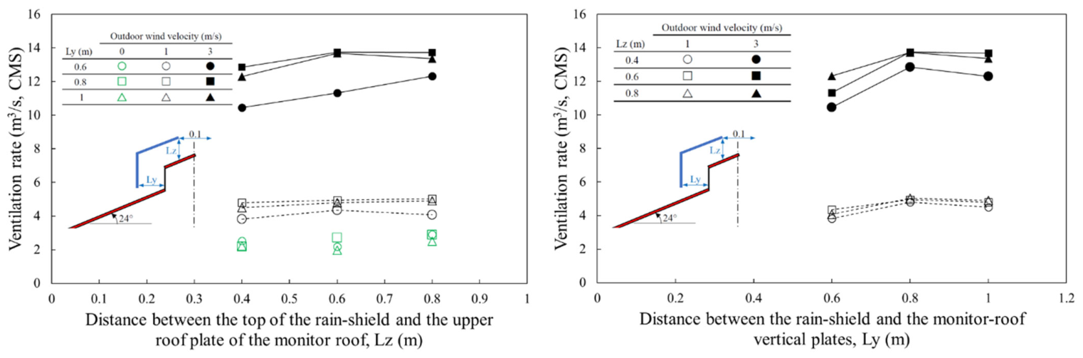
Under lateral wind conditions (wind approaching angle = 90°), the ventilation behavior of the rain-shield monitor roof exhibits characteristics that are markedly different from those observed under normal and oblique wind incidence, as shown in Figure 7. Overall, the ventilation rate still increases significantly with increasing outdoor wind speed, indicating that wind-driven ventilation remains the primary driving source. However, compared with the 0° and 45° wind cases, the extent to which geometric design parameters can regulate ventilation performance is clearly constrained, indicating that the ventilation behavior enters a momentum-limited regime governed by inlet conditions.
Figure 7.
Effects of the vertical clearance Lz and lateral spacing Ly on the ventilation rate (CMS) of the modified monitor roof under different outdoor wind speeds for the 90° wind-approaching case. The (left) and (right) panels correspond to Lz and Ly, respectively.
Figure 7 (left) indicates that the ventilation rate under wind-driven conditions varies only slightly with Lz. Across different Ly configurations, modifying Lz results in only limited changes in ventilation rate, implying that outlet height is not a primary factor governing ventilation performance when the wind approaches laterally. This result reflects that when the external wind field predominantly sweeps laterally past the monitor roof, the influence of outlet geometry on the effective pressure difference and induction effect is substantially reduced.
Figure 7 (right) shows that Ly has a more consistent effect on ventilation performance under lateral wind conditions. At a given wind speed and Lz, variations in Ly lead to only minor changes in ventilation rate. This indicates that, within a momentum-limited regime, the primary role of Ly is to facilitate the guidance of airflow into the tower rather than to substantially increase the ventilation rate. Relative sensitivity to Ly is 15.8%. When Ly is small, the lateral flow passage helps concentrate the limited external momentum and directs airflow into the tower; as Ly increases, the guiding effect weakens, and the airflow becomes more prone to deflection and dissipation, resulting in a noticeable reduction in ventilation rate. This trend remains consistent across different Lz conditions, demonstrating that the influence of Ly is highly stable under lateral wind scenarios.
Taken together, these results indicate that when the wind approaching angle is 90°, the ventilation behavior of the rain-shield monitor roof transitions from geometry-induced or geometry–flow interaction–dominated mechanisms to a momentum-limited ventilation mode governed by inlet conditions. In this scenario, Lz serves only as a secondary adjustment parameter, whereas Ly becomes the key geometric factor determining the lower bound of ventilation performance. This behavior can be regarded as a robustness test of the rain-shield monitor roof under unfavorable wind directions, reflecting its conservative ventilation performance in real building environments characterized by high wind-direction uncertainty.
3.4. Findings: Interaction Between Wind Direction and Geometric Control Mechanisms
The results presented in Section 3.1, Section 3.2 and Section 3.3 demonstrate that the ventilation performance of rain-shield monitor roofs is governed by the combined influence of wind-driven and buoyancy-driven mechanisms. The interaction between the external airflow and the geometric configuration of the monitor roof determines the pressure distribution and airflow acceleration around the roof opening, which ultimately affects the ventilation rate.
Under wind-dominant conditions, the approaching airflow interacts with the monitor-roof structure and generates localized pressure differences across the inlet and outlet openings. The geometric parameters of the roof influence the flow contraction and acceleration near the outlet region, thereby affecting the overall ventilation capacity. In particular, the outlet height (Lz) modifies the effective flow path and the aerodynamic interaction between the external wind field and the roof opening.
The results indicate that an intermediate outlet height (Lz = 0.6 m) generally provides more favorable ventilation performance compared with lower or higher configurations. This behavior suggests that an appropriate balance between outlet elevation and airflow resistance is necessary to achieve efficient ventilation. When the outlet height is too small, the airflow passage becomes restricted, while an excessively large outlet height may weaken the pressure-driven airflow interaction near the roof opening.
The lateral spacing parameter (Ly) also affects the airflow path within the monitor-roof system. Variations in Ly modify the available flow passage and the associated flow resistance, thereby influencing the resulting ventilation rate.
When the approaching wind speed is very low or zero (Vo = 0), the ventilation process is primarily governed by buoyancy-induced airflow generated by the temperature difference between the heated roof surface and the ambient air. In this case, the stack effect becomes the dominant driving force, and the influence of geometric parameters on ventilation performance becomes less pronounced compared with wind-driven conditions.
Overall, the results suggest that the ventilation performance of rain-shield monitor roofs is controlled by the interaction between roof geometry and the dominant ventilation mechanism. The findings provide useful insights into the design of monitor-roof ventilation systems in industrial buildings operating under hybrid natural ventilation conditions.
4. Conclusions and Design Implications
This study investigated the ventilation performance of rain-shield monitor roofs under hybrid natural ventilation conditions using CFD simulations. The effects of key geometric parameters, including the outlet height (Lz) and lateral spacing (Ly), were systematically examined under different approaching wind directions and wind speeds.
The results indicate that wind direction plays a decisive role in determining the ventilation behavior and the effectiveness of geometric design parameters. Under normal wind incidence (0°), ventilation performance is primarily governed by geometric configuration. In this regime, Lz exhibits an optimal range associated with outlet-induction effects, whereas Ly consistently controls the development of airflow momentum within the internal flow passage. Under oblique wind conditions (45°), the ventilation mechanism transitions to a geometry–flow interaction regime, in which the sensitivity of ventilation performance to geometric parameters becomes weaker due to the influence of the external roof shear layer. When the wind approaches laterally (90°), the ventilation behavior further shifts to a momentum-limited regime. In this situation, the influence of outlet height becomes significantly reduced, while the lateral spacing mainly determines whether the external airflow can be effectively guided into the monitor-roof tower.
Among the investigated configurations, an intermediate outlet height of approximately Lz ≈ 0.6 m generally produced higher ventilation rates compared with lower (0.4 m) or higher (0.8 m) outlet heights. This observation suggests that an appropriate balance between outlet elevation and flow resistance is required to achieve efficient ventilation performance. The lateral spacing parameter Ly also plays an important role in shaping the internal airflow passage. Within the investigated range, a spacing of approximately Ly = 0.6–0.8 m appears to provide favorable airflow guidance while avoiding excessive flow resistance.
Under purely buoyancy-driven conditions (Vo = 0), the airflow is primarily governed by the stack effect induced by the temperature difference between the roof surface and the ambient air. In this case, the influence of geometric parameters on ventilation performance becomes less pronounced compared with wind-driven conditions.
Based on these findings, several design implications can be proposed for industrial buildings equipped with rain-shield monitor roofs. First, selecting an outlet height close to Lz ≈ 0.6 m can help maintain favorable ventilation performance within the investigated design range. Second, maintaining a lateral spacing of approximately Ly = 0.6–0.8 m can provide an effective airflow passage without introducing excessive flow resistance. Although the present study focuses on a representative industrial building configuration, the identified airflow mechanisms are expected to remain applicable to buildings with similar monitor-roof ventilation systems.
The design implications of this study should be interpreted within the scope of the investigated configuration. The recommended values of Lz ≈ 0.6 m and Ly = 0.6–0.8 m were obtained from a representative industrial building model with fixed geometry, roof inclination, rain-shield configuration, wind-speed range, and thermal boundary condition. They should therefore be regarded as favorable ranges within the present design space, rather than universal optimal dimensions. In real buildings, variations in building scale, roof slope, opening arrangement, internal partitions, equipment layout, heat-source distribution, and partially opened doors or windows may alter airflow resistance and ventilation performance. Moreover, the present study used roof-level ventilation rate as the primary performance indicator; it did not evaluate air change efficiency, mean age of air, pollutant removal, local thermal comfort, or wind-driven rain intrusion.
Nevertheless, the wind-direction-dependent mechanism identified in this study provides a transferable design concept. Ventilation is mainly geometry-dominated under normal wind incidence, governed by geometry–flow interaction under oblique wind incidence, and more strongly momentum-limited under lateral wind incidence. Future work should examine different building scales, roof slopes, rain-shield proportions, internal layouts, transient wind and thermal conditions, additional indoor air-distribution indices, and quantitative wind-driven rain performance to develop more generalized design guidance for rain-shield monitor roofs.
Author Contributions
K.S.Y. and Y.-P.L. conceived of and designed the model; K.S.Y. performed the simulation works; K.S.Y. and Y.-P.L. analyzed the data; Y.-P.L. and C.-M.L. wrote the paper. All authors have read and agreed to the published version of the manuscript.
Funding
This research received no external funding.
Data Availability Statement
Data available on request.
Acknowledgments
This work was supported by the National Science and Technology Council (NSTC), Taiwan, under Project No. NSTC 114-2622-E-006-014. The authors are also grateful to Huang and Tung Associates Architects for their valuable input on the practical design of monitor roofs.
Conflicts of Interest
The authors declare no conflicts of interest.
References
- Jomehzadeh, F.; Hussen, H.M.; Calautit, J.K.; Nejat, P.; Ferwati, M.S. Natural ventilation by windcatcher (Badgir): A review on the impacts of geometry, microclimate and macroclimate. Energy Build. 2020, 226, 110396. [Google Scholar] [CrossRef] [Scilit]
- Izadyar, N.; Miller, W.; Rismanchi, B.; Garcia-Hansen, V. Impacts of façade openings’ geometry on natural ventilation and occupants’ perception: A review. Build. Environ. 2020, 170, 106613. [Google Scholar] [CrossRef] [Scilit]
- Zhang, H.; Yang, D.; Tam, V.W.Y.; Tao, Y.; Zhang, G.; Setunge, S.; Shi, L. A critical review of combined natural ventilation techniques in sustainable buildings. Renew. Sustain. Energy Rev. 2021, 141, 110795. [Google Scholar] [CrossRef] [Scilit]
- Tariku, F.; Iffa, E.D. Temperature and air flow patterns in attic roofs. J. Archit. Eng. 2017, 23, 04017014. [Google Scholar] [CrossRef] [Scilit]
- Valovirta, I.; Hietikko, J.; Tuominen, E.; Yletyinen, K.; Vinha, J. Hygrothermal performance of ventilated attics: A field study in cold climate. Build. Environ. 2024, 266, 112114. [Google Scholar] [CrossRef] [Scilit]
- Chu, C.R.; Lan, T.W. Effectiveness of ridge vent to wind-driven natural ventilation in monoslope multi-span greenhouses. Biosyst. Eng. 2019, 186, 279–292. [Google Scholar] [CrossRef] [Scilit]
- Villagrán, E.; Bojacá, C. Study using a CFD approach of the efficiency of a roof ventilation closure system in a multi-tunnel greenhouse for nighttime microclimate optimization. Rev. Ceres 2020, 67, 345–356. [Google Scholar] [CrossRef] [Scilit]
- Wang, Y.; Zhao, T.; Cao, Z.; Zhai, C.; Wu, S.; Zhang, C.; Zhang, Q.; Lv, W. The influence of indoor thermal conditions on ventilation flow and pollutant dispersion in downstream industrial workshop. Build. Environ. 2021, 187, 107400. [Google Scholar] [CrossRef] [Scilit]
- Cao, Z.; Liu, Y.; Bai, Y.; Wang, Y.; Ye, S.; Cao, H. Study on the optimal layout of roof vents and rooftop photovoltaic of the industrial workshop. Build. Environ. 2024, 260, 111624. [Google Scholar] [CrossRef] [Scilit]
- Ho, M.L.; Yew, M.C.; Yew, M.K.; Saw, L.H.; Yuen, R.K.K.; Tan, W.C.; Yeo, W.H.; Yit, J.E. Numerical simulation of a pioneering cool roof system for Asia’s roofing system reformation: The alternative cooling measure. Alex. Eng. J. 2024, 102, 211–222. [Google Scholar] [CrossRef] [Scilit]
- Chen, C.M.; Lin, Y.P.; Chung, S.C.; Lai, C.M. Effects of the design parameters of ridge vents on induced buoyancy-driven ventilation. Buildings 2022, 12, 112. [Google Scholar] [CrossRef] [Scilit]
- Lin, Y.P.; Huang, T.L.; Chung, S.C.; Lai, C.M. Effect of outdoor wind on the hybrid natural ventilation performance of monitor roofs. Alex. Eng. J. 2023, 80, 584–593. [Google Scholar] [CrossRef] [Scilit]
- Win, S.L.Y.; Chiang, Y.C.; Lin, Y.P.; Lai, C.M. Effect of rain shelter installation on the natural ventilation performance of monitor roofs. Int. J. Vent. 2024, 24, 97–110. [Google Scholar] [CrossRef] [Scilit]
- Spalding, D.B. The PHOENICS Encyclopedia; CHAM Ltd.: London, UK, 2012. [Google Scholar]
- Franke, J.; Hellsten, A.; Schlunzen, H.; Carissimo, B. Best Practice Guideline for the CFD Simulation of Flows in the Urban Environment; COST Office: Brussels, Belgium, 2007. [Google Scholar]
- Tominaga, Y.; Mochida, A.; Yoshie, R.; Kataoka, H.; Nozu, T.; Yoshikawa, M.; Shirasawa, T. AIJ guidelines for practical applications of CFD to pedestrian wind environment around buildings. J. Wind Eng. Ind. Aerodyn. 2008, 96, 1749–1761. [Google Scholar] [CrossRef] [Scilit]
- Blocken, B. Computational fluid dynamics for urban physics: Importance, scales, possibilities, limitations and ten tips and tricks towards accurate and reliable simulations. Build. Environ. 2015, 91, 219–245. [Google Scholar] [CrossRef] [Scilit]

Disclaimer/Publisher’s Note: The statements, opinions and data contained in all publications are solely those of the individual author(s) and contributor(s) and not of MDPI and/or the editor(s). MDPI and/or the editor(s) disclaim responsibility for any injury to people or property resulting from any ideas, methods, instructions or products referred to in the content. |
© 2026 by the authors. Licensee MDPI, Basel, Switzerland. This article is an open access article distributed under the terms and conditions of the Creative Commons Attribution (CC BY) license.