


Abstract
Grouted sleeve connectors are critical components in precast concrete structural joints. This study investigates the effects of grouting defect location, quantity, and grout strength on the bond–slip constitutive relationship at the steel–grout interface in fully grouted sleeves. Fifteen centrally loaded pull-out specimens were designed using the controlled variable method and tested under monotonic tension. Failure modes, ultimate load, bond stress, and slip characteristics were analyzed. Numerical modeling was performed using ABAQUS, and a mathematical bond–slip constitutive model was developed. The experimental results show that all specimens with a single defect failed by tensile fracture of the reinforcing bar, whereas those with multiple defects exhibited bar pull-out failure, which most significantly degraded connection performance. Grout strength positively correlated with interfacial bond performance. Deviation of the water-to-binder ratio from the standard value reduced grout strength, leading to decreases in bond strength, ultimate load, and slip. The apparent increase in bond stress under multiple defects was attributed to the reduced effective anchorage area rather than enhanced interfacial bonding, resulting in the lowest actual ultimate load among all scenarios. The established bond–slip constitutive model achieved a coefficient of determination R2 ≥ 0.96, indicating excellent fit. The finite element simulations agreed well with test data and accurately reproduced the bond–slip response under various defect conditions. The proposed constitutive model and finite element modeling approach provide a theoretical and quantitative basis for performance assessment of grouted sleeve connectors in engineering practice.
1. Introduction
Grouted sleeve connections have gained prominence in prefabricated concrete structures since the 21st century due to their cost-effectiveness, ease of construction, and reliable performance. This connection method involves embedding sleeves in precast members, inserting steel bars, and grouting to achieve continuous force transfer between rebars. Currently, it is one of the primary methods for connecting stressed reinforcement in prefabricated concrete structures in China [1,2].
As critical components ensuring structural safety and stability, grouted sleeve connections have attracted extensive research attention from scholars and engineers worldwide. Existing investigations on grouted sleeve connectors are mainly experimental, and a number of studies have focused on the overall mechanical performance of the connectors [3,4,5,6,7,8,9,10], such as load–elongation response, failure modes, and the nominal “bond strength” derived from the global load response. Liu et al. [11] established the bond–slip constitutive relationship between grout and high-strength reinforcing bars by taking bar diameter and anchorage length as variables, and proposed formulas for calculating bond strength, peak slip, and residual bond strength between steel bars and grout. Xu et al. [12] conducted tests on the local and global bond–slip behaviors of grouted sleeve connections, investigated the influences of anchorage length, longitudinal bar eccentricity, and loading history, and developed an analytical bond–slip model covering both local and global responses. Jelawy et al. [13] established bond–slip constitutive models for different regions within grouted sleeves through experiments and finite element simulations, with connector dimensions, bar diameter, and splicing condition as parameters; they found that connectors can fully utilize the ultimate stress of reinforcing bars, and the strain ratio between the joint region and the reinforcing bar decreases with increasing sleeve size. Feng et al. [14] studied the relationship between the load–slip response of grouted sleeve connections and reinforcement anchorage length using experimental and numerical methods. Zhao et al. [15] carried out tensile tests to analyze the influence of anchorage length on failure modes of grouted sleeves, and derived a formula for predicting ultimate bond strength as well as a recommended value for the minimum anchorage length. Shang et al. [16] realized effective detection of grouting defects in sleeves using the impact-echo method combined with finite element simulation and experiments, and proposed optimal sensor arrangements and quality evaluation criteria, providing valuable references for related research. Lang et al. [17] systematically investigated the tensile performance of grouted sleeve connections via experiments and refined finite element analysis, revealing the load-transfer mechanism and failure characteristics of such connections.
To date, most studies assume that grouted sleeves are perfectly filled. However, in engineering practice, various grouting defects inevitably occur due to on-site construction influences such as air bubbles, blockage, and grout leakage. Espoir et al. [18] studied partially grouted sleeves with defects and found that such defects significantly degrade the ultimate bearing capacity. Grouting defects in sleeves not only substantially weaken the connection performance but also threaten the stability and reliability of prefabricated buildings. Many scholars at home and abroad have also investigated the effects of grouting defects on the mechanical behavior of grouted sleeves. Li et al. [19] investigated the mechanical properties of sleeves with horizontal grouting defects after exposure to elevated temperatures, providing an experimental basis for evaluating connection performance under the coupled effects of defects and high temperatures. Ren et al. [20] adopted defect location (end defect, middle defect, uniform defect, unilateral defect, and horizontal defect) and defect length as experimental variables and concluded that grouting defects degrade the bond performance between grout and reinforcing bars. Yang et al. [21] experimentally investigated the cyclic tensile performance of half-grouted sleeve connections with various grouting defects and revealed the influences of defects on hysteretic behavior, bearing capacity, and energy dissipation capacity. Zhang et al. [22] conducted experimental research on the seismic performance of prefabricated bridge pier joints using half-grouted sleeve and socket composite connections, supporting the seismic design and engineering application of such composite joints. Leibovich and Yankelevsky [23] studied the pull-out bond behavior of ribbed reinforcing bars in concrete with recycled concrete aggregates, providing a theoretical reference for reinforcement anchorage design in recycled aggregate concrete members. Guo et al. [24] experimentally studied the mechanical performance of fully grouted sleeve connectors with different grouting defects and clarified the influences of defect type and severity on connection behavior. Chen et al. [25] experimentally investigated the mechanical properties of half-grouted sleeve connections with grouting defects and identified the effects of defects on bearing capacity, slip response, and failure modes. The bond performance between ribbed reinforcing bars [26,27] and plain reinforcing bars [28,29] and concrete has been widely studied. Researchers have confirmed that chemical adhesion and friction contribute to the bond stress between plain bars and concrete, whereas mechanical interlocking dominates the bond stress between ribbed bars and concrete.
Therefore, this study designs 15 grouted sleeve connection specimens for axial tensile tests to systematically investigate the effects of grouting defect characteristics (location and extent), grout strength, and anchorage length on the bearing capacity and bond performance. Finite element analysis using ABAQUS is employed to simulate realistic conditions and analyze the bond stress–slip response at the bar–grout interface. The findings aim to establish a constitutive model that can serve as a theoretical and practical reference for performance assessment and engineering application of grouted sleeve connections.
2. Test Overview
2.1. Specimen Design
To characterize the bond–slip constitutive relationship at the steel–grout interface under practical construction conditions, fifteen full-scale pull-out specimens of fully grouted sleeve connectors were fabricated, incorporating simulated grouting defects representative of common field imperfections. The experimental variables included defect location (top, middle, end, and uniform distribution), defect extent, and grout strength. Through systematic pull-out testing, the effects of these defect parameters on the bond–slip response and corresponding constitutive behavior of the sleeve connectors were quantitatively evaluated.
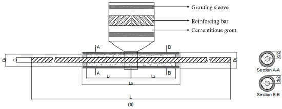
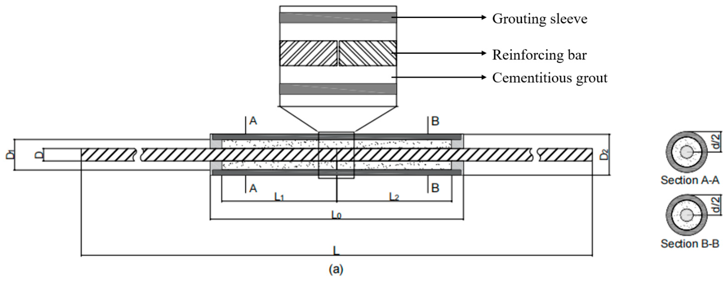
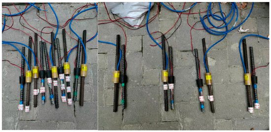
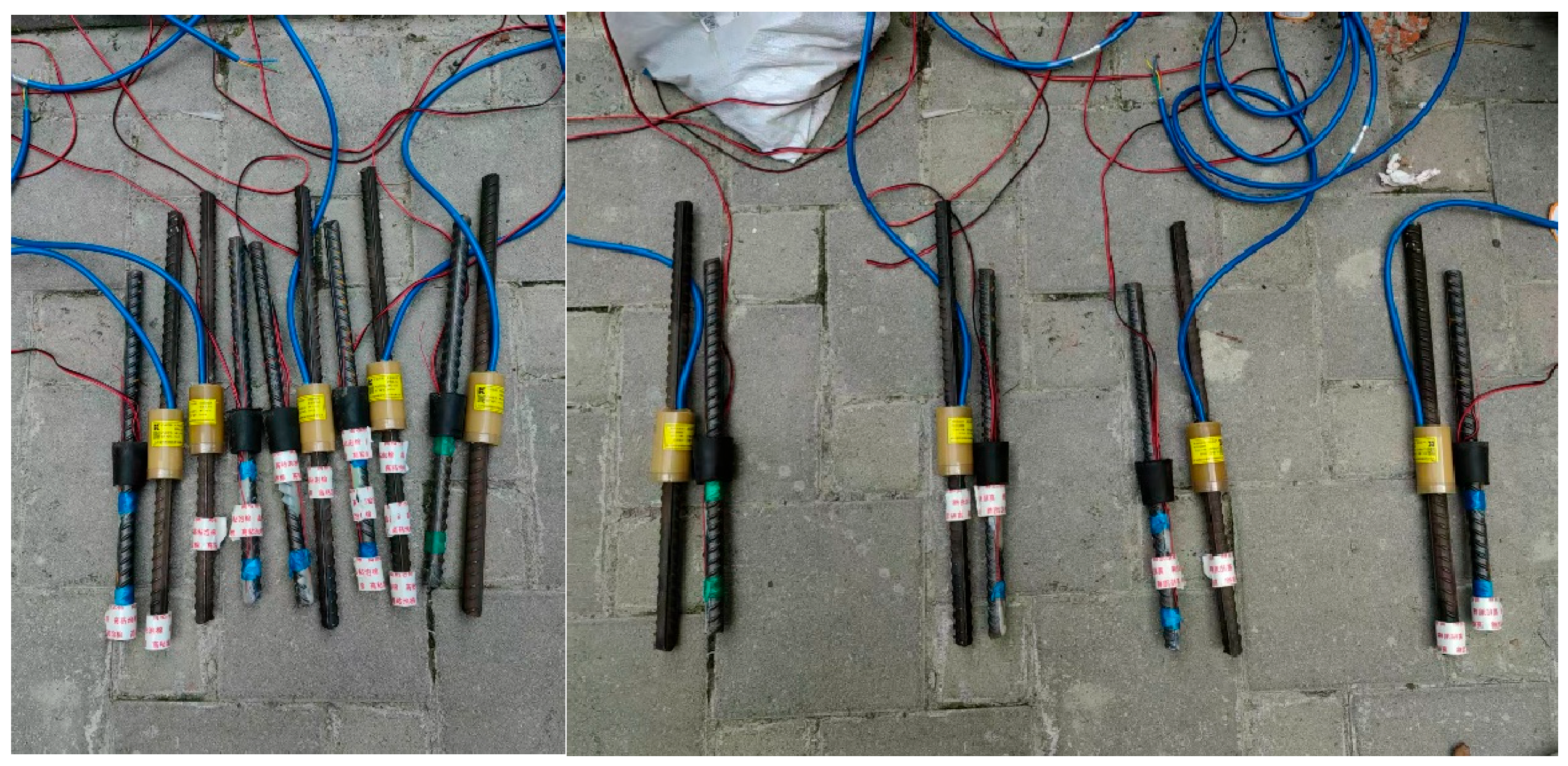
The full-scale grouted sleeve connectors employed in this experimental program were fabricated from Grade 45 high-quality carbon structural steel, a material widely adopted in Chinese construction practice. The spliced steel reinforcement consisted of HRB400-grade deformed bars with a diameter of 14 mm, a nominal cross-sectional area of 153.9 mm2, and a total length of 350 mm. All specimen preparation, grouting, and testing procedures strictly adhered to the Chinese technical specifications for grout sleeve splicing (JGJ 355-2015) and mechanical splicing of steel reinforcement (JGJ 107-2016). Key geometric and material parameters are summarized in Figure 1 and Table 1. For each defect configuration, three replicate specimens were fabricated with distinct grout strength grades to examine the influence of grout material properties. To isolate the variables of interest, temperature and humidity effects were controlled by fabricating and curing all specimens under consistent environmental conditions.
Figure 1.
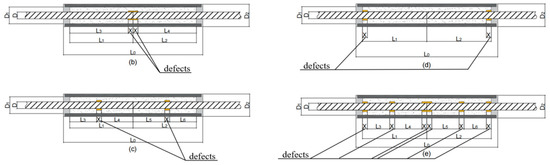
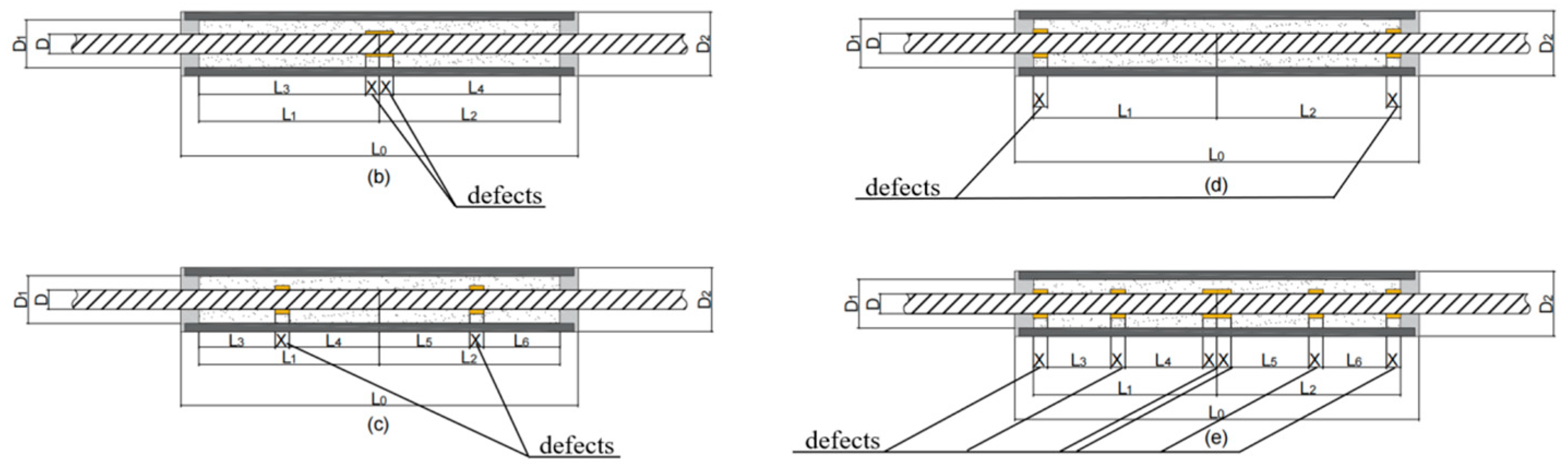
Schematic diagram and cross-section of grouted sleeve connector details ((a) Specimen without defect (b–d) Specimens with single defect (end, middle and top). (e) Specimen with multiple defects.
Table 1.
Detailed Parameters of Grouted Sleeve Connection Specimens (Unit: mm).
2.2. Material Properties
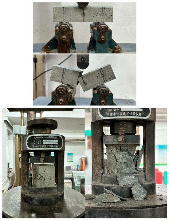
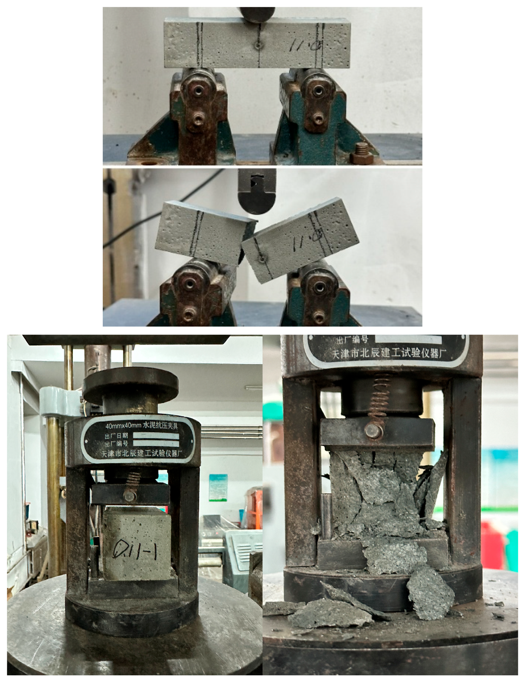
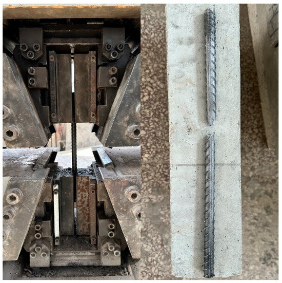
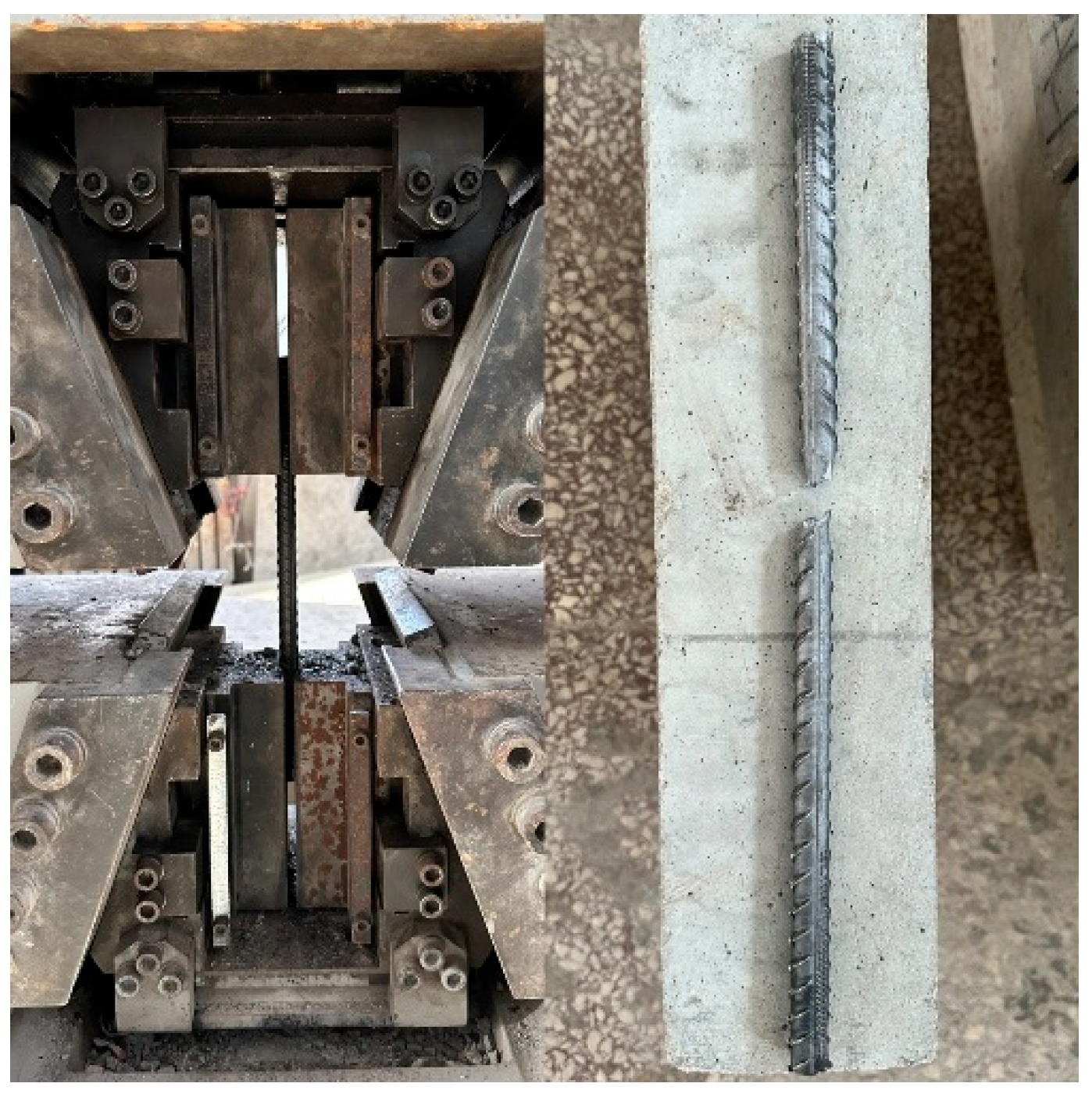
In compliance with the Chinese industry standard Sleeve Grout for Rebar Splicing (JG/T 408-2013), three grout mixtures with varying strength grades were formulated by adjusting the water–binder ratio to 0.11, 0.12, and 0.13, designated as Mix A, B, and C, respectively. To characterize the mechanical properties of the grout and the steel reinforcement, prismatic specimens (40 mm × 40 mm × 160 mm) and cubic specimens (40 mm × 40 mm × 40 mm) were cast for flexural and compressive testing, respectively, while standard tensile coupons were prepared from the steel bars. The specimen configurations and test setups are illustrated in Figure 2 and Figure 3, and the resulting material properties are summarized in Table 2.
Figure 2.
Flexural test of prismatic grout specimens and compressive test of cubic grout specimens.
Figure 3.
Tensile Strength Test of HRB400 Steel Bars.
Table 2.
Material Properties.
2.3. Arrangement of Grouting Defects
In this test, the foam embedding method was adopted to fabricate grouting defects. Prior to grouting, foam materials cut to the designed dimensions were precisely fixed at the preset defect positions inside the sleeve and closely attached to the surface of steel bars, so as to prevent grout from infiltrating into the defect area. After grouting and standard curing, the embedded foam remained on the steel bar surface to form defect cavities with clear boundaries and regular shapes. The adopted foam material ensured no deformation during grouting and could be firmly fixed at the designated defect locations.
Three working conditions were designed in the test, including defect-free condition, single-defect condition and uniformly distributed multi-defect condition. The single-defect condition was further divided into three types: end defect, middle defect and top defect, while the multi-defect condition consisted of multiple cavities uniformly distributed along the anchorage length.
All defects were designed as longitudinally cylindrical cavities coaxial with the steel bar inside the sleeve, featuring an annular cross-section. The inner diameter of the annular defect was consistent with the nominal diameter of HRB400 steel bar, namely 14 mm, and the outer diameter was 16 mm. The axial length of all single defects (end, middle and top defects) was set to a unified value. For uniformly distributed multi-defects, multiple short cylindrical cavities were arranged at equal intervals along the effective anchorage length. The specific position, segment length and spatial distribution of all defects were strictly implemented in accordance with the designed specimen dimensions. The schematic diagram of defect arrangement is shown in the following Figure 4.
Figure 4.
Schematic layout of grouting defects.
2.4. Test Setup and Loading Protocol
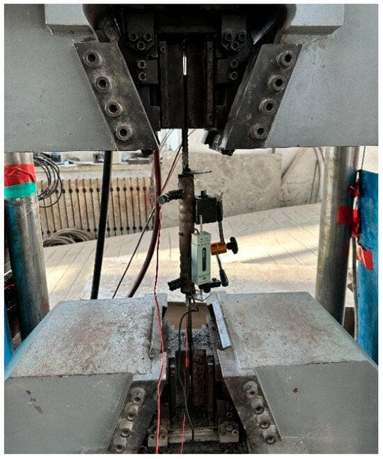
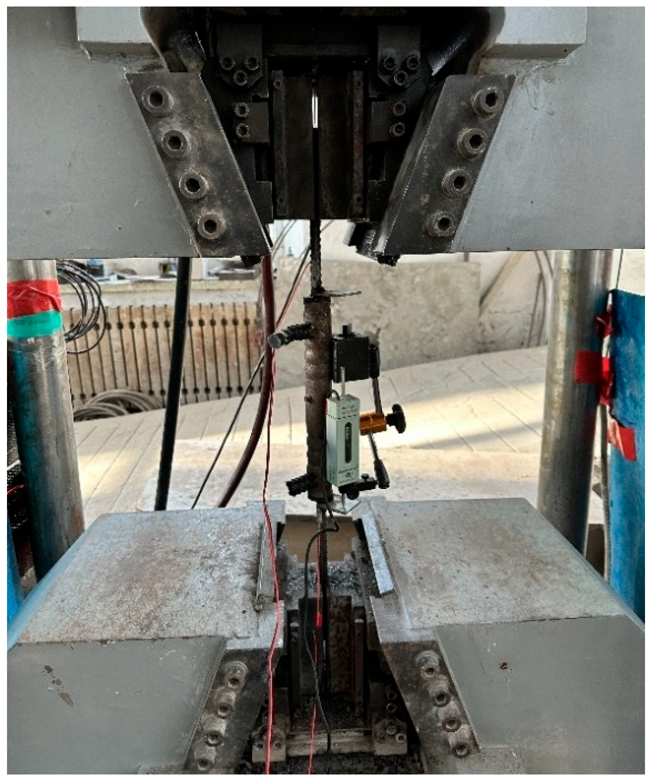
The tensile test setup is illustrated in Figure 5. A 600 kN universal testing machine (UTM) was employed to perform uniaxial tensile tests in strict accordance with the relevant technical specifications. Load was applied monotonically at one end of the specimen until failure. The loading protocol consisted of displacement-controlled loading from zero to the ultimate tensile capacity, with termination criteria defined as the point at which the interfacial bond stress between the steel bar and grout reached its peak value in the strain-hardening stage.
Figure 5.
Test Loading Device.
The entire test was conducted under displacement control, with the relative displacement between the reinforcing bar and the surrounding grout within the sleeve serving as the control parameter. The grip separation rate was maintained at 20 mm/min throughout the test. As depicted in Figure 5, a YHD-50 displacement transducer was mounted at the sleeve end to monitor the slip response. The transducer was installed with its contact plate flush against the sleeve end face (zero initial gap) to ensure direct measurement of relative displacement. Slip data were sampled at 1 Hz and recorded in real time with a resolution of 0.001 mm to enhance measurement accuracy and minimize experimental error.
This test arrangement complies with the current relevant test specifications and is also a widely adopted method in the research on bond–slip behavior of grouted sleeve connections. Nevertheless, it still has certain limitations. Measuring only the end slip cannot directly obtain the local bond–slip distribution along the anchorage length, making it difficult to reflect the non-uniform development of bond action and the internal stress transfer process at different positions. The monotonic uniaxial tensile loading adopted in the test corresponds to an ideal stress state. In practical engineering structures, components are usually subjected to cyclic loading, combined tension-bending action or complex stress conditions, and their bond degradation and slip responses may differ from those observed in this study. Even so, the end slip can effectively characterize the overall bond–slip performance, and has been proven to be sufficiently reliable for evaluating the ultimate bearing capacity, failure mode and macroscopic bond–slip constitutive relationship.
During the tensile testing of fully grouted sleeve connectors, the primary response parameters measured were the global load–displacement response and the relative slip at the steel–grout interface. The global load–displacement curve was recorded directly by the integrated data acquisition system of the universal testing machine. The relative end slip of the reinforcing bar with respect to the sleeve was monitored using a YHD-50 electronic displacement transducer, and the corresponding signal was logged by a static resistance strain indicator synchronized with the loading system.
3. Calculation of Bond Stress at the Steel Bar–Grout Interface of Grouted Sleeve Connectors
The ultimate bond stress τᵤ represents the average bond force per unit contact area at the steel bar–grout interface, which is directly related to the bearing capacity of grouted sleeve connectors. The bond stress at the steel bar–grout interface is defined as the ratio of the peak load sustained by the grouted sleeve connector to its effective anchorage area, as given in the following equation:
where denotes the bond stress at the steel bar–grout interface; Pu denotes the load applied to the fully grouted sleeve connector; lm denotes the anchorage length; and ds denotes the nominal diameter of the steel bar.
For defect-free specimens, lm is taken as the full anchorage length of the reinforcing bar inside the sleeve. For single-defect specimens, the length of the defective segment is deducted from the total anchorage length. For multi-defect specimens, the effective anchorage length is determined by summing the lengths of all intact contact segments after subtracting the lengths of all uniformly distributed defective sections. In this study, the effective anchorage length of each specimen with different defect types is determined strictly following the above principle, ensuring that the calculated bond stress conforms to the actual interfacial stress state.
This calculation method assumes a uniform distribution of bond stress along the anchorage length, which is currently the most commonly used and convenient macroscopic evaluation approach for grouted sleeve connection tests. However, when grouting defects exist, especially under multi-defect and uniformly distributed defect conditions, the actual contact interface between the reinforcing bar and grout becomes discontinuous, and the internal stress transfer path is interrupted. Accordingly, the interfacial stress is no longer uniformly distributed but exhibits characteristics of local stress concentration and segmented force transfer. Consequently, the adoption of average bond stress simplifies the actual stress distribution to a certain extent and cannot reflect the local stress peak and stress gradient along the anchorage length.
Nevertheless, the average bond stress can still macroscopically characterize the overall interfacial bearing capacity, facilitate comparative analysis among different defect conditions, and meet the basic requirements of engineering performance evaluation and parametric law analysis. In subsequent refined research, local stress measurement techniques or numerical simulation methods can be adopted to further reveal the actual stress distribution along the anchorage length.
The experimental results for all specimens are compiled in Table 3. The specimen nomenclature is defined as follows: the first part denotes the grouting defect configuration, where EDS indicates an end defect, CDS a central defect, TDS a top defect, UDES a uniformly distributed defect, and NDS a defect-free (reference) specimen; the second part specifies the water-to-binder ratio of the grout mixture, corresponding to 0.11, 0.12, and 0.13, respectively.
Table 3.
Test Results of Various Specimens.
4. Test Results and Analysis
4.1. Failure Modes
In the technical domain of grouted sleeve splicing for steel reinforcement, the failure mode serves as a critical indicator for assessing the connection performance. The failure mechanism of a grouted sleeve specimen is governed by the ultimate tensile capacity of the steel bar and the interfacial bond stress between the bar and the grout. Based on the experimental observations in this study, two primary failure modes were identified, as detailed below:
(1) Tensile Fracture of Steel Reinforcement
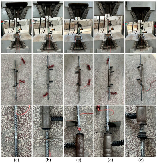
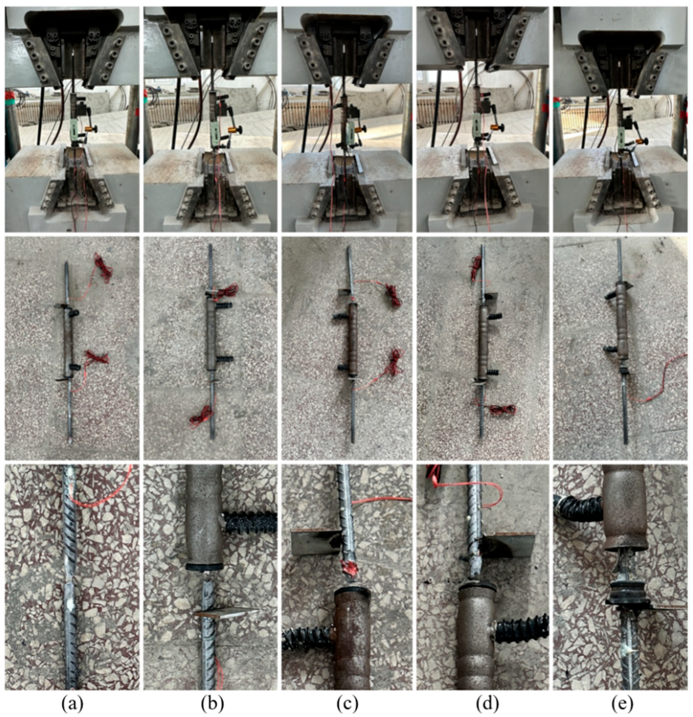
Tensile fracture of the reinforcing bar occurs when the interfacial bond strength exceeds the ultimate tensile capacity of the bar. As shown in Figure 6a–d, this failure mode was observed in specimens that were either defect-free or contained a single localized grouting defect. During the initial loading stage, the specimen exhibited a linear elastic response. Concurrently, microcracks initiated in the grout near the specimen end, aligned with the rib geometry of the deformed bar, and propagated gradually, leading to a continuous reduction in specimen stiffness. Upon yielding of the steel bar, noticeable elongation of the bar was recorded. After yielding, the specimen entered the strain-hardening stage, during which both load and slip increased progressively. After attaining the peak load, a rapid load drop occurred within a very limited slip increment. The tensile fracture of the bar took place on the descending branch of the load–displacement curve, preceded by pronounced necking, ultimately resulting in bar rupture and termination of the test.
Figure 6.
Schematic Diagram of Failure Phenomena ((a) Specimen without defect (b–d) Specimens with single defect (end, middle and top). (e) Specimen with multiple defects).
For specimens that failed by bar fracture, the absence or limited extent of grouting defects prevented the shear stress within the grout from reaching the ultimate bond strength at the steel–grout interface, whereas the steel bar first attained its ultimate tensile strength, leading to tensile fracture. This indicates that, under external loading, the mechanical capacity of the steel bar was exhausted before the bond performance between the bar and the grout reached its limit, thereby governing the failure mode in defect-free or minimally defective specimens.
(2) Pull-Out Failure of Steel Reinforcement
Pull-out failure occurs when the interfacial bond strength is lower than the ultimate tensile capacity of the reinforcing bar. As shown in Figure 6e, this failure mode was observed in specimens containing multiple or distributed defects, such as those with uniformly distributed grouting voids. During the initial loading stage, the specimen exhibited an elastic response. However, due to the insufficient bond capacity, microcracks initiated at the interface between the grout and the bar near the specimen end. As the applied load increased, the bar displacement grew progressively, which was reflected in the increasing readings of the electronic displacement transducer. Once the interfacial bond resistance was exceeded under the imposed loading, the grout–bar interface underwent complete debonding. This resulted in the bar being pulled out from the grouted sleeve, accompanied by an immediate termination of the loading process.
Specimens that experienced pull-out failure contained extensive grouting defects, leading to a distinct failure mechanism compared to other defect configurations. In such cases, the inherent strength of the grout material was not fully mobilized. The presence of substantial defects prevented the development of adequate interfacial bond stress, causing premature bond failure before the bar could reach its tensile capacity. This failure mode directly illustrates the detrimental influence of grouting defects on connection performance. Even when the grout possesses adequate compressive strength, severe bond degradation due to defects can trigger premature bar pull out, resulting in a non-ductile failure of the spliced connection.
4.2. Parametric Analysis
4.2.1. Influence of Defect Location and Number
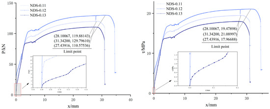
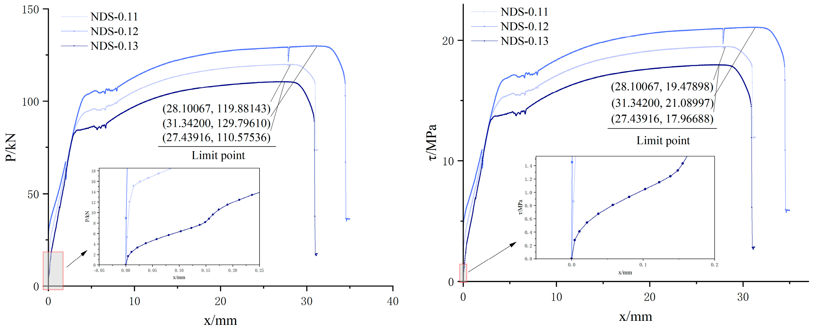
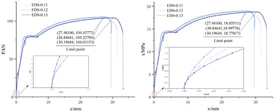
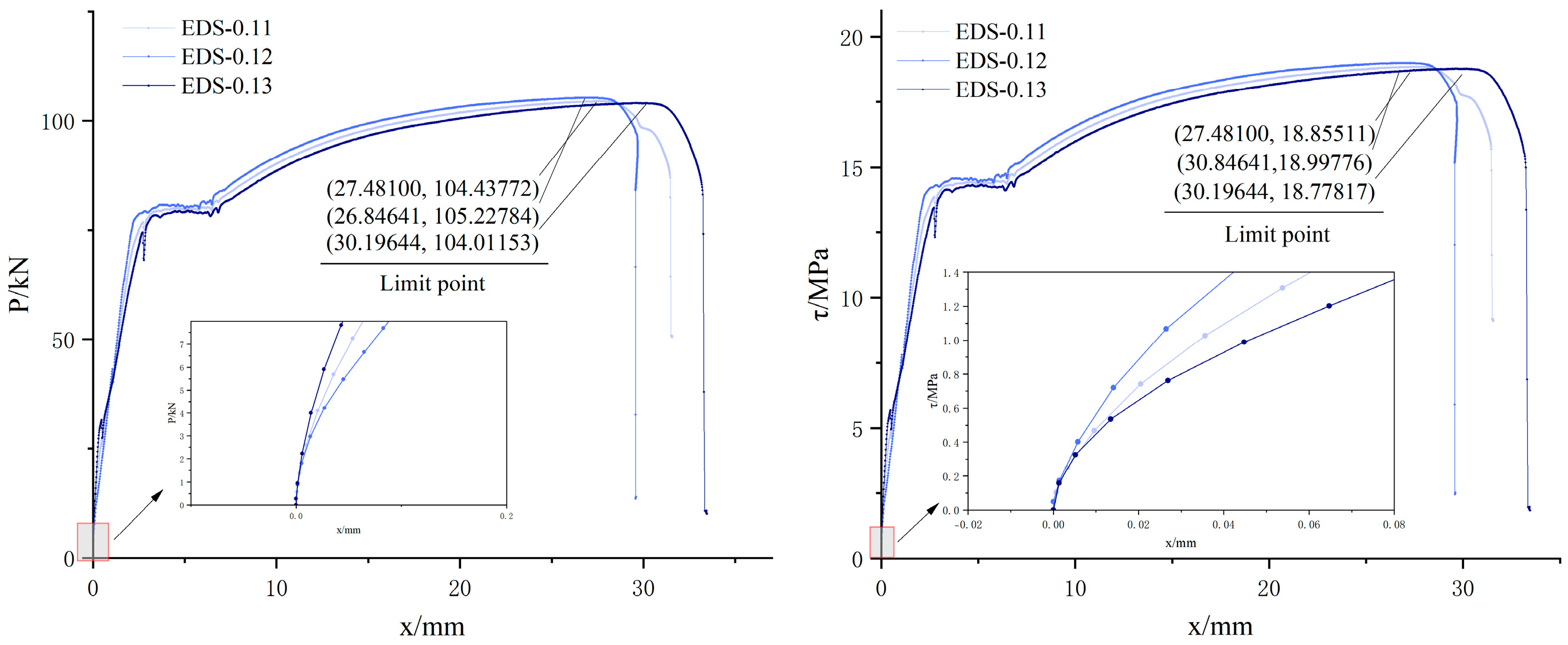
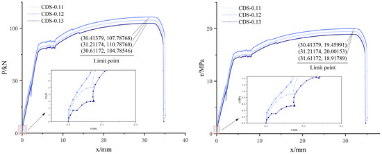
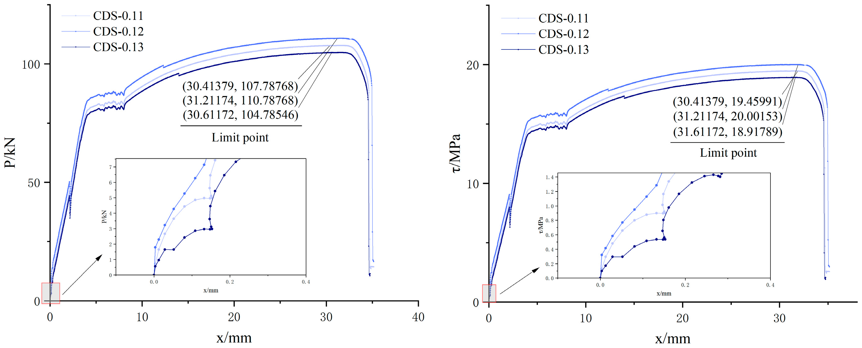
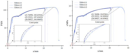
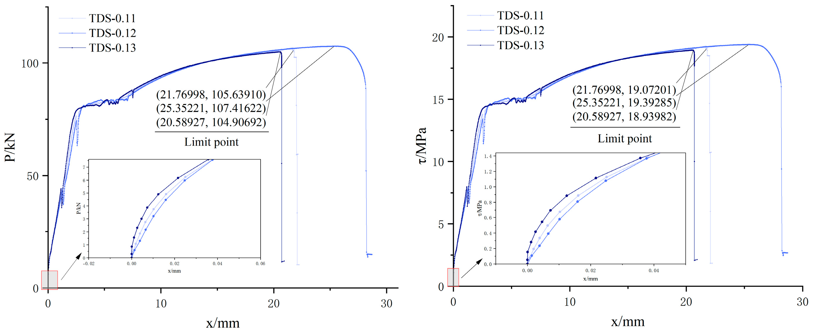
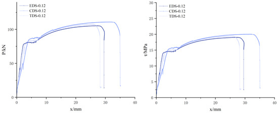
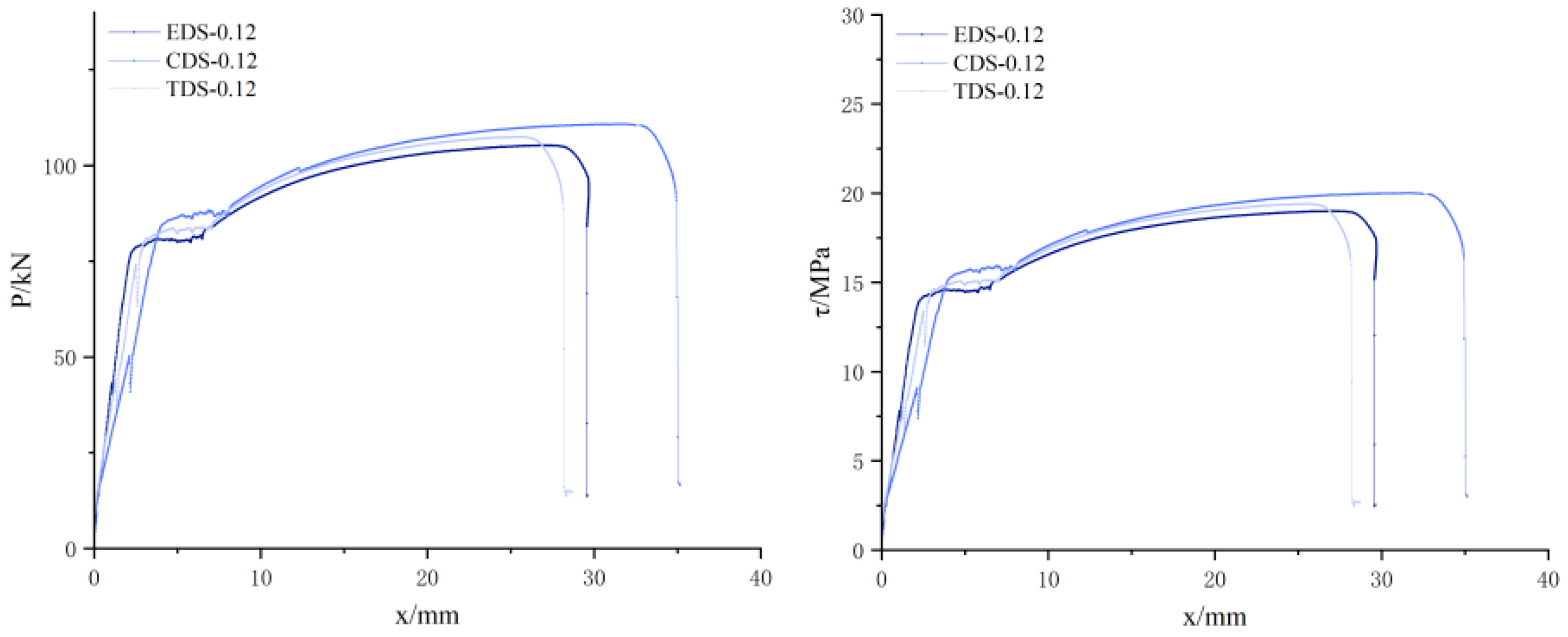
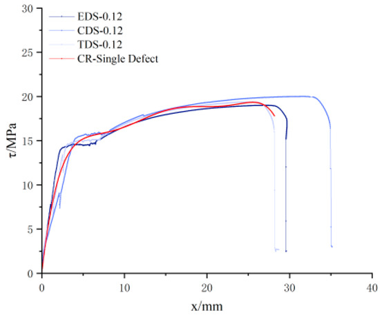
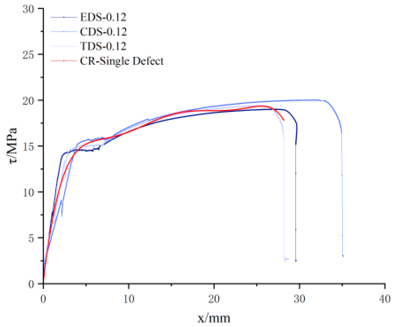
Figure 7, Figure 8, Figure 9, Figure 10 and Figure 11 illustrate the load-carrying capacity of the specimens and the corresponding bond stress–slip curves under varying grout strengths and defect configurations. For the defect-free specimen, the ultimate load reached 129.80 kN, the corresponding slip measured 31.34 mm, and the peak bond stress attained 21.09 MPa. In specimens containing a single localized defect (end, middle, or top) with the same nominal anchorage length, both the ultimate load and slip were reduced. The ultimate loads were 105.23 kN, 110.79 kN, and 107.42 kN, slips measured 30.85 mm, 31.21 mm, and 25.35 mm, and peak bond stresses reached 19.00 MPa, 20.00 MPa, and 19.39 MPa, respectively.
Figure 7.
Bearing Capacity–Slip Curves and Bond–Slip Curves of No Defect Specimens.
Figure 8.
Bearing Capacity–Slip Curves and Bond–Slip Curves of End Defect Specimens.
Figure 9.
Bearing Capacity–Slip Curves and Bond–Slip Curves of Central Defect Specimens.
Figure 10.
Bearing Capacity–Slip Curves and Bond–Slip Curves of Top Defect Specimens.
Figure 11.
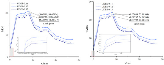
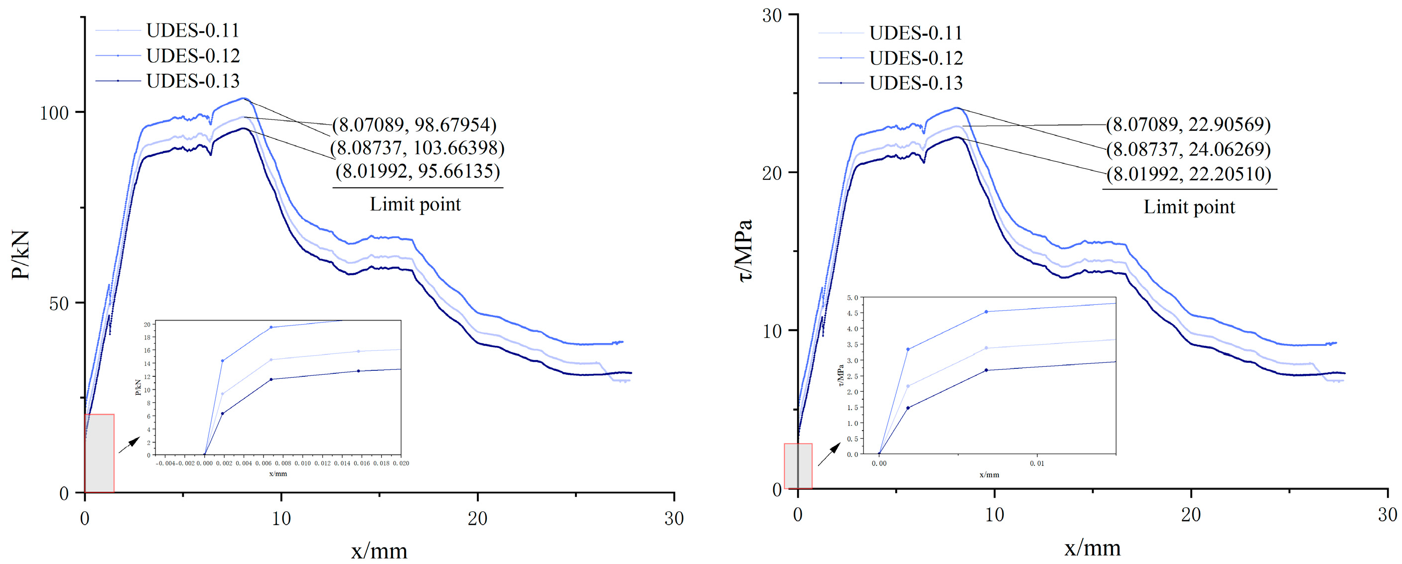
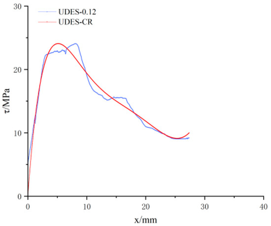
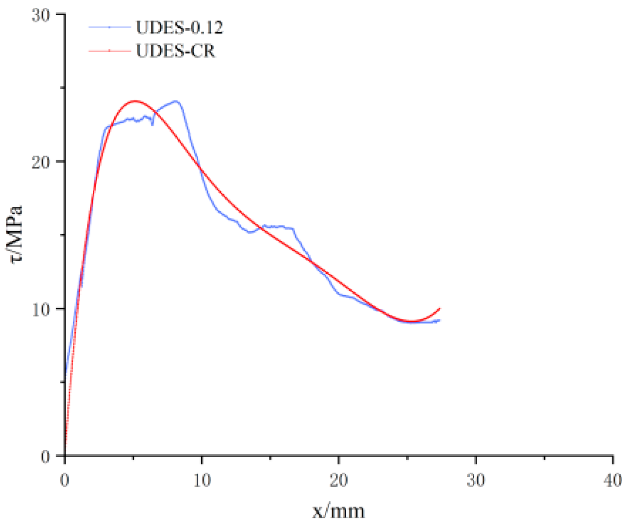
Bearing Capacity–Slip Curves and Bond–Slip Curves of Uniformly Distributed Defect Specimens.
In specimens with multiple distributed defects, the effective anchorage length was substantially reduced, resulting in a significant decrease in both ultimate load (103.66 kN) and slip (8.09 mm) compared to other defect configurations. Notably, a sharp and transient increase in bond stress to 24.06 MPa was observed during the hardening stage, accompanied by a shift in failure mode from tensile fracture to bar pull-out. Analysis of the test data indicates that this increase in bond stress was not a result of continuous hardening, but rather an abrupt jump followed by a gradual decline. This phenomenon is attributed to the reduction in effective bonded area, which elevates the average bond stress per unit area without an actual increase in overall load-carrying capacity, as further demonstrated in subsequent bond stress calculations.
Although the ultimate bearing capacity, slip capacity and maximum bond stress of specimens with single defects are lower than those of defect-free specimens, the differences in mechanical parameters among the three types of single defects are insignificant. All single-defect specimens maintain the failure mode of steel bar fracture without altering the fundamental force transfer mechanism of the bonding interface, indicating that the influence of defect location on the structural performance of specimens with local single defects is relatively limited.
By comparison, the number of defects exerts a more critical influence on mechanical behavior. The multi-defect condition is essentially characterized by an increased number of defects and their full-range distribution along the anchorage length. Comparative analysis of test data shows that the bond stress under multi-defect conditions does not increase steadily, but rises abruptly at a certain stage and then decreases continuously. Combined with the experimental results and Equation (1), where lm refers to the effective anchorage length, uniformly distributed multi-defects greatly reduce the effective contact length between the reinforcing bar and grout, which sharply decreases the effective anchorage area. Although the ultimate load Pu of multi-defect specimens is remarkably lower than that of other groups, the tensile force borne per unit contact area is correspondingly enlarged, resulting in an overestimation of the apparent bond stress.
Quantitatively, compared with defect-free specimens, the effective anchorage area of multi-defect specimens is reduced by about 25–30%, while the reduction in ultimate bearing capacity exceeds 19%. As the reduction ratio of anchorage area is greater than that of ultimate load, the calculated bond stress presents an artificially high value. The sudden rise of bond stress does not originate from the improvement of the inherent bearing capacity of the specimen, but from the reduction of effective anchorage area. The decreased contact area increases the bond force borne per unit area, thereby causing an abrupt increase in apparent bond stress, while the actual load-bearing capacity of the specimen is not improved at all.
This phenomenon is well verified by the transformation of failure mode from steel bar fracture to bar pull-out. The premature failure of the bond interface and the drastic reduction of effective force transfer region are the essential reasons for the lowest bearing capacity and sharply decreased slip of multi-defect specimens, rather than the enhancement of interfacial bond strength. The above quantitative analysis and failure characteristic comparison collectively reveal that the elevated bond stress under multi-defect conditions is merely an apparent result induced by geometric effects, rather than an actual improvement in the mechanical performance of the bonding interface.
4.2.2. Influence of Water-to-Solid Ratio of Grout
The water-to-binder ratio of the grout significantly influences the mechanical performance of the connection. In this experimental program, three water-to-binder ratios were examined, with 0.12 designated as the standard reference mix. Relative to the standard mix (water-to-binder ratio = 0.12), a reduction in the water-to-binder ratio to 0.11 led to consistent but varied degradation in ultimate load, slip, and peak bond stress across all defect configurations. For defect-free specimens, ultimate load and peak bond stress decreased by 7.64%, while slip was reduced by 10.34%. Specimens with end, middle, top, and multiple defects exhibited ultimate load/peak bond stress reductions of 0.80%, 2.71%, 1.93%, and 4.81%, and slip reductions of 10.91%, 2.56%, 14.13%, and 0.20%, respectively.
Similarly, increasing the water-to-binder ratio to 0.13 resulted in further reductions in performance. Compared to the standard mix, defect-free specimens showed a 4.81% decrease in ultimate load and peak bond stress, and a 12.32% reduction in slip. For specimens containing end, middle, top, and multiple defects, the corresponding ultimate load/peak bond stress decreased by 1.16%, 5.42%, 2.33%, and 7.72%, with slip reductions of 2.11%, 1.92%, 18.79%, and 0.83%, respectively.
The observed variations in bond strength arise from changes in the grout’s mechanical properties induced by adjustments in the water-to-binder ratio. As the water-to-binder ratio deviates from the standard value, the grout strength departs from its optimum, thereby affecting the interfacial shear capacity. The bond between the reinforcing bar and grout is primarily governed by the shear resistance of the mechanical interlock zone. Consequently, an increase in grout strength enhances the shear capacity of the interlock region, which in turn elevates the overall bond strength at the steel–grout interface.
4.2.3. Comparative Analysis of Bond–Slip Behavior of Specimens with Single Grouting Defect
A comparative assessment of the bond–slip performance was conducted on specimens with three distinct localized defect configurations (As shown in Figure 12), including end defect, middle defect, and top defect, fabricated with the standard grout mixture having a water to binder ratio of 0.12. The experimental results show that all specimens containing such individual defects exhibited tensile fracture failure of the reinforcing bar. The measured ultimate load, slip, and bond stress values for the three defect types were closely comparable, yet consistently lower than those recorded for defect-free reference specimens.
Figure 12.
Bearing Capacity–Slip Curves and Bond–Slip Curves of Specimens with Single Grouting Defect at Standard Water-to-Binder Ratio.
Among the three individual defect patterns, specimens with a middle defect demonstrated the highest ultimate load capacity. Relative to this configuration, the end defect specimens showed a 5.02% reduction in ultimate load, while the top defect specimens exhibited a 3.04% reduction. The slip corresponding to the middle defect condition was also the largest among the three, although the slip magnitudes across all configurations remained within a similar range. Furthermore, the bond slip constitutive curves for the three defect types displayed fundamentally consistent evolutionary trends, with only marginal variations in mechanical response. These findings suggest that, within the scope of the tested individual defect patterns, the specific defect location, whether end, middle, or top, imposes a comparable level of influence on the interfacial bond slip behavior between the steel reinforcement and the grout material.
5. Establishment of Interfacial Bond–Slip Constitutive Relationship Between Steel Bar and Grout in Fully Grouted Sleeves Under Different Grouting Defects
Using the standard grout mix with a water to binder ratio of 0.12 as the reference, a constitutive model was developed to accurately characterize the interfacial mechanical behavior of fully grouted sleeves under various defect configurations. The model was established based on experimentally measured bond stress slip data, thereby providing a mathematical basis for finite element simulations and engineering calculations of load-bearing capacity. In this study, a unified function form was employed to describe the interfacial bond slip constitutive relationship between the steel bar and grout in grouted sleeves across all defect types:
where τ denotes the average interfacial bond stress between reinforcing bar and grout under the standard water-to-binder ratio of grout, serving as a core index to characterize the interfacial bonding strength; x represents the relative slip between reinforcing bar and grout in fully grouted sleeves, which quantifies the relative displacement of the interface; and A, B, C, D, E and F are the characteristic coefficients of the sixth-order polynomial, corresponding to the weight of each power term of slip respectively.
The sixth-order polynomial is adopted to establish the bond–slip constitutive model of the bar–grout interface, aiming to characterize the complex nonlinear relationship between bond stress and slip, rather than theoretical derivation based on specific mechanical assumptions. Under various grouting defect conditions, the evolution of bond stress with slip exhibits highly nonlinear behavior, including obvious ascending, peak and descending segments, which cannot be fully described by conventional low-order functions. The sixth-order polynomial can directly describe the numerical correlation between slip and bond stress via a single continuous expression without piecewise definition or additional constraint conditions, featuring the simplest form and excellent convenience in numerical calculation and program application.
Compared with widely used bond–slip models such as hyperbolic and exponential functions, the proposed sixth-order polynomial model achieves higher overall fitting accuracy with experimental data. It can directly output the bond stress corresponding to arbitrary slip values, and is easy to be assigned and embedded in finite element modeling with stable calculation and good convergence performance, which can efficiently meet the practical requirements of engineering numerical analysis and parametric calculation. Therefore, the sixth-order polynomial model is selected to fit the experimental data in this study.
The coefficient of determination R2 is adopted as the primary evaluation index for model fitting accuracy, while the mean absolute error (MAE) and root mean square error (RMSE) are supplemented for quantitative analysis. The evaluation criteria are defined as follows: the closer R2 is to 1, and the smaller the MAE and RMSE, the better the model fitting performance. When R2 ≥ 0.96, the model is considered to accurately reflect the variation law of experimental data. The higher order terms of the polynomial provide the flexibility to accommodate the pronounced nonlinearity inherent in the bond–slip relationship, enabling accurate representation of the characteristic response under various defect scenarios. This establishes a high-fidelity constitutive basis for subsequent finite element simulations. Model parameters were fitted using the least squares method, whereby the sum of squared residuals between predicted and measured values was minimized through iterative computation. Validation confirmed that the sixth order polynomial exhibited both high fitting accuracy and strong adaptability; it was therefore selected for regression of the experimental data. The coefficient of determination R2 was employed as the primary metric for evaluating model accuracy, with R2 ≥ 0.96 indicating that the model reliably captures the underlying variation in the test data.
where n is the number of data points, is the bond stress calculated by the constitutive model, and denotes the experimentally measured bond stress.
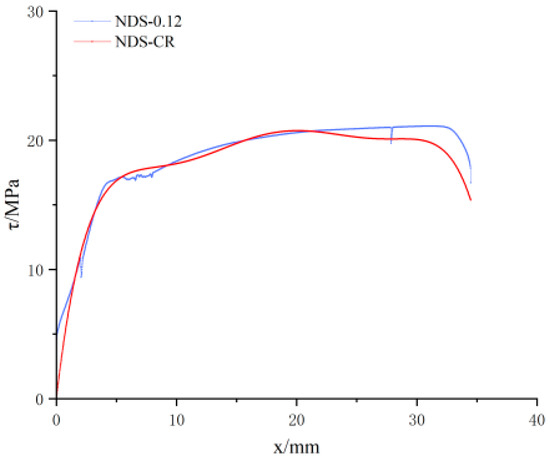
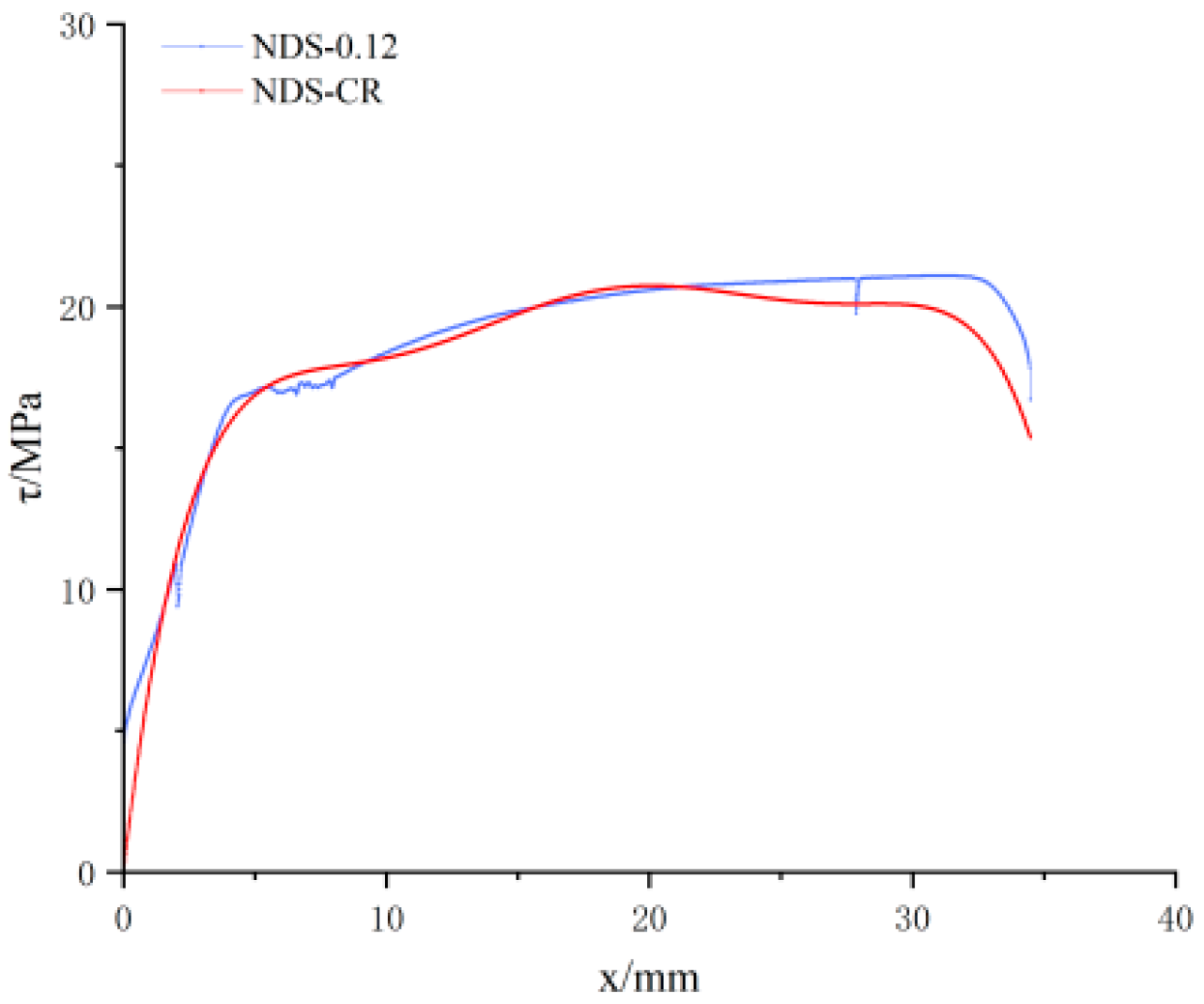
Based on sixth order polynomial regression, the resulting fitted parameters and corresponding bond–slip curves are summarized in Table 4 and presented graphically in Figure 13, Figure 14 and Figure 15.
Table 4.
Data Sheet of Interfacial Bond–Slip Constitutive Relationship Between Steel Bar and Grout.
Figure 13.
Bond–Slip Constitutive Relationship Curve of Defect-Free Specimen.
Figure 14.
Bond–Slip Constitutive Relationship Curve of Specimen with Single Defect.
Figure 15.
Bond–Slip Constitutive Relationship Curve of Specimen with Multiple Defects.
The order of the polynomial model was determined through comparative trial calculations of multiple function orders. Low-order polynomials from second-order to fifth-order were initially adopted in this study. The results indicate that low-order functions cannot completely characterize the full nonlinear evolution of bond–slip curves under various grouting defect conditions, including the ascending segment, peak point, and post-peak descending stage. In contrast, the sixth-order polynomial can accurately reproduce the complete experimental curve using a unified mathematical expression. Moreover, the proposed model effectively avoids overfitting problems. A consistent function form is applied to all specimens without deliberately adjusting fitting parameters for individual curves. All fitted curves exhibit reasonable variation trends, and the coefficient of determination R2 of each specimen remains higher than 0.96, demonstrating stable and satisfactory fitting accuracy. Furthermore, the sixth-order polynomial possesses excellent robustness and favorable numerical convergence, which is applicable to defect-free, single-defect, and multi-defect specimens. Higher-order polynomials (seventh order or above) were abandoned in this study because redundant parameters inevitably induce curve distortion and overfitting, without obvious improvement in fitting precision. Consequently, the sixth-order polynomial is determined as the optimal choice considering fitting accuracy, physical rationality of curves, and model robustness.
Nevertheless, the proposed sixth-order empirical bond–slip model has definite application boundaries and limitations, rather than unconditional universality. In terms of material properties, this model is only applicable to the high-strength grout and HRB400 ribbed steel bars adopted in the present test. For ultra-high-strength steel bars, special corrosion-resistant steel bars, or innovative grouting materials with distinct mechanical characteristics, the interfacial force transfer mechanism changes significantly, which may cause calculation errors if the current fitting parameters are directly applied. Regarding geometric conditions, all experimental data are obtained based on fixed anchorage length, standard sleeve inner diameter, and conventional bar diameter. Significant variations in key geometric parameters, such as anchorage length, sleeve dimension, and bar diameter ratio, will alter the interfacial stress transfer path and confinement effect, thereby invalidating the existing fitting coefficients. From the perspective of defect conditions, this model is established for typical localized and intermittent grouting voids, and it is not applicable to severely deteriorated interfaces such as extensive honeycomb voids, large-area interface peeling, and penetrating incompact grouting defects, where the bond failure mechanism completely deviates from the experimental characteristics in this study.
Overall, the empirical model maintains reliable applicability only for conventional high-strength grout systems, standard sleeve geometric sizes, and moderate localized grouting defects. Re-calibration of fitting parameters is required when extending the model to alternative materials, geometric configurations, or extreme defect conditions. Future research can expand the database covering diverse materials, specimen sizes, and extreme defect working conditions to optimize the model formulation and improve its general applicability for broader engineering scenarios.
6. Finite Element Analysis of Interfacial Bond–Slip Between Steel Bar and Grout
6.1. Establishment of the Finite Element Model
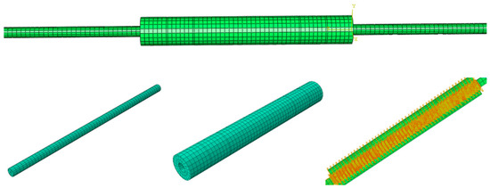
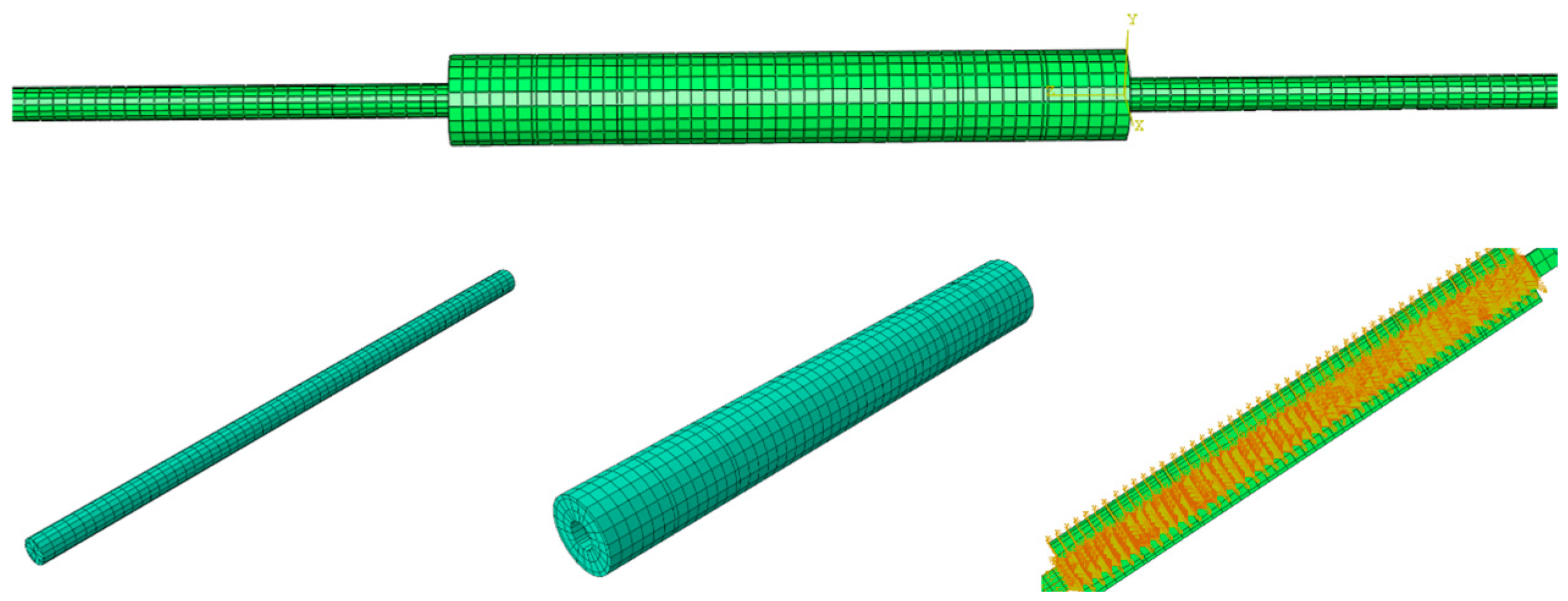
In this study, the finite element software ABAQUS 2024 was adopted to establish a tensile numerical model for fully grouted sleeve connections to accurately simulate the mechanical behavior of sleeves, reinforcing bars and grout. The concrete damaged plasticity (CDP) model was used to characterize the mechanical performance of grout, and its constitutive relationship was determined in accordance with (GB 50010-2010, 2015 Edition). The material properties of reinforcing bars and grouted sleeves were defined based on the national standard for HRB400 ribbed bars and the mechanical parameters of QT400 ductile iron sleeves, respectively. All components were meshed using hexahedral solid elements with consistent mesh matching. Refined meshes were arranged at the critical contact interface between steel bars and grout to capture local stress concentration and damage evolution. The interfacial bond behavior between reinforcing bars and grout was simulated by spring elements incorporated with the proposed sixth-order polynomial constitutive model, and the relevant parameter settings were determined based on the research of Lang et al. [17]. The comparative validation indicates that the numerical curves are in excellent agreement with the experimental and fitted curves, with the deviations of peak stress and peak slip controlled within 5%. Mesh division and spring connection are shown in Figure 16.
Figure 16.
Finite Element Model and Spring Connection Diagram for Interaction.
6.2. Finite Element Curve Analysis of Interfacial Bond–Slip Between Steel Bar and Grout
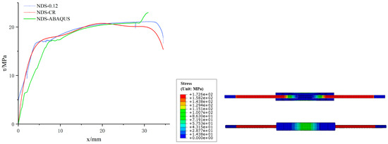
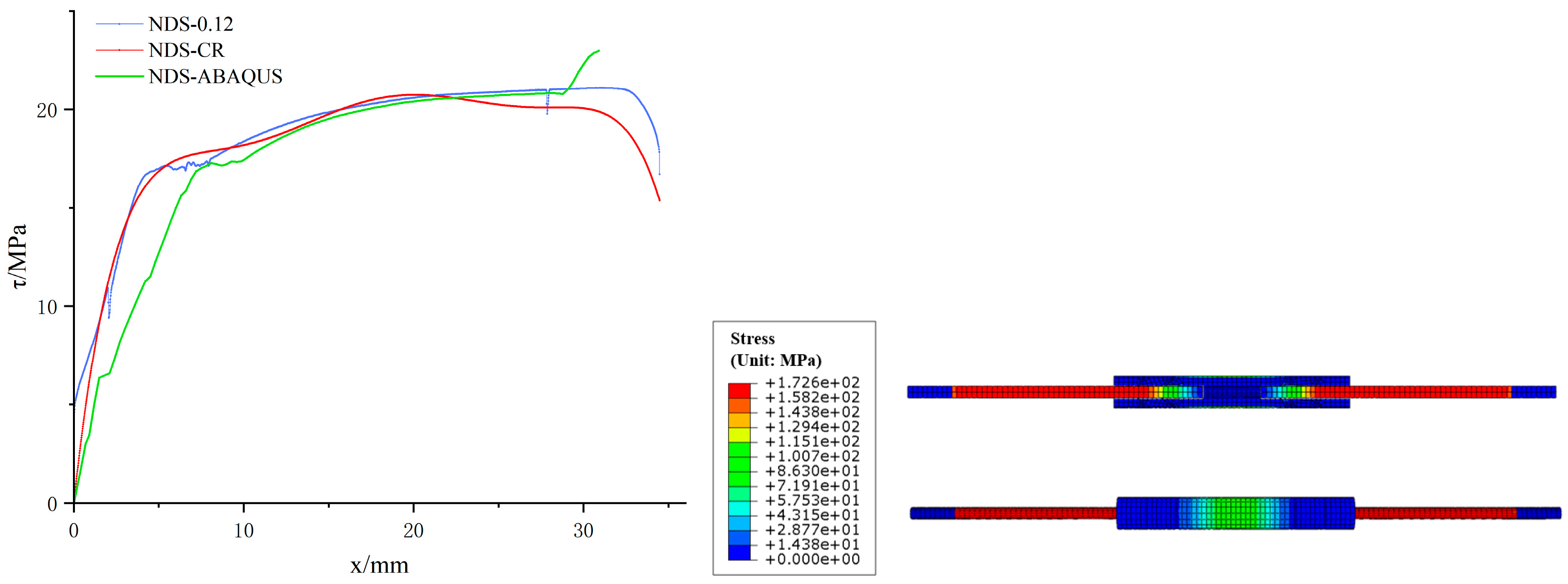
Finite element simulations of the bond slip behavior of fully grouted sleeve connectors with various defect locations were conducted using ABAQUS, from which the corresponding bond slip responses (denoted as “ABAQUS curves”) were extracted. To validate the rationality and accuracy of both the finite element model and the constitutive model in capturing interfacial bond slip behavior, a comparative analysis was performed among the simulated curves, the experimentally measured bond slip curves obtained under the standard mix (water to binder ratio = 0.12), and the sixth order polynomial fitted constitutive relationship curves (denoted as “CR curves”). The comparative results for each scenario are presented in Figure 17, Figure 18 and Figure 19.
Figure 17.
Bond–Slip Finite Element Curve of Defect-Free Specimen.
Figure 18.
Bond–Slip Finite Element Curves of Specimens with Single Defect.
Figure 19.
Bond–Slip Finite Element Curves of Specimens with Multiple Defects.
For the intact specimen, the finite element bond–slip curve exhibits a high degree of consistency with both the experimental curve and the constitutive relationship curve throughout the entire slip range (Figure 17). This agreement aligns with the progressive mobilization mechanism of interfacial bonding under the intact condition and accurately reproduces the stress evolution along a fully bonded interface. The simulation captures key bonding characteristics of the intact interface: the ascending branch slope matches closely with the experimental and constitutive curves, indicating consistent interfacial stiffness in the elastic stage. The peak bond stress of 21.09 MPa is attained at a slip of approximately 31.34 mm, with deviations in both slip and stress at the peak below 2%, demonstrating accurate representation of bond-strength growth in the hardening stage. And the post-peak response shows a gradual decay that remains in phase with the test curve.
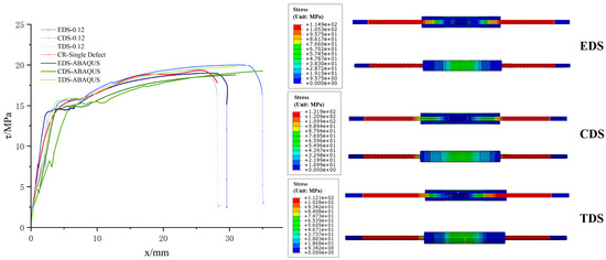
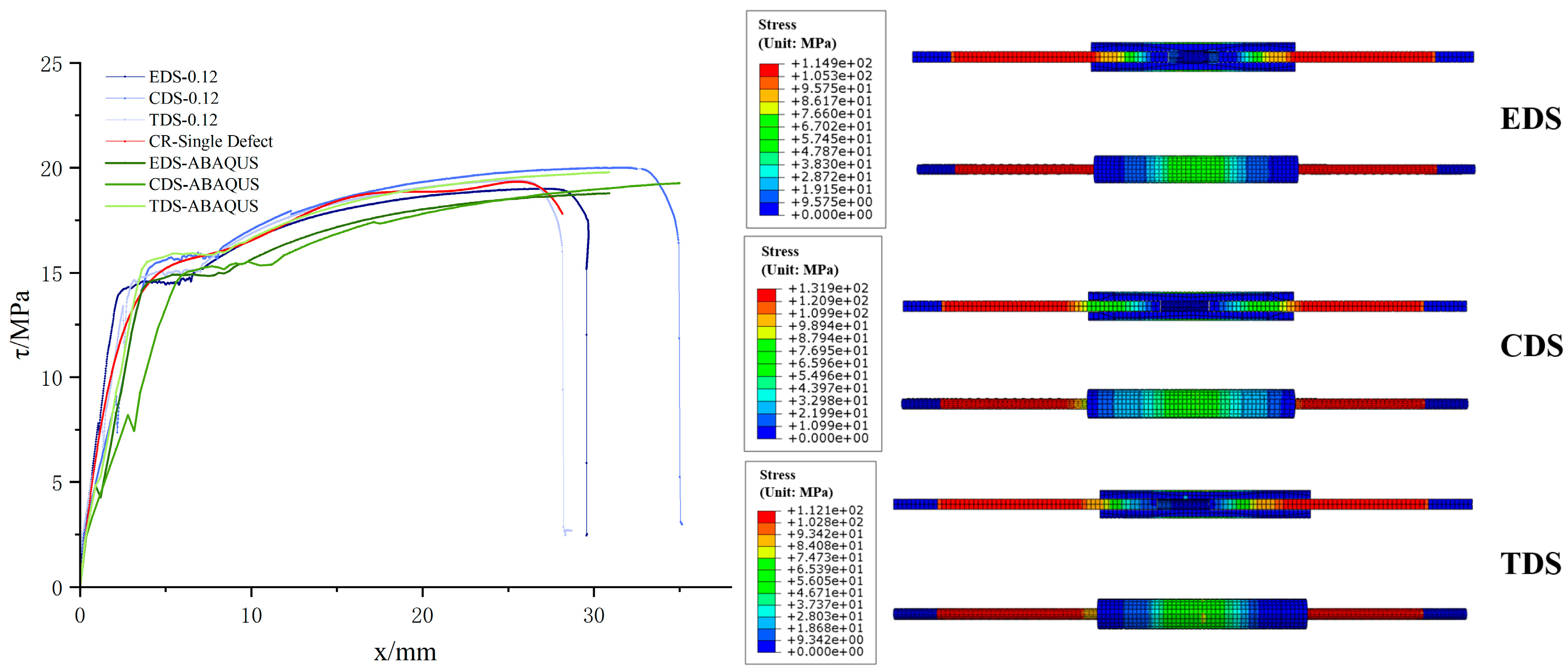
The bond–slip responses obtained from finite element analysis for specimens containing individual defects (end, middle, and top) align well with the variation patterns observed in both experimental measurements and the corresponding constitutive relationship curves (denoted as CR-Single Defect curves, Figure 17). The overall consistency of the curve shapes across the three defect configurations confirms that a single localized defect does not fundamentally alter the core load-transfer mechanism at the steel–grout interface. The simulations successfully captured subtle differences in interfacial stress behavior induced by the three defect locations: the finite element curve for the middle-defect specimen exhibits the closest agreement with the test and constitutive curves, with a peak-point deviation below 3%, indicating that a mid-length defect exerts the least degradation on interfacial bond performance. The curve for the end-defect specimen shows a slight divergence in the post-peak branch, with deviation controlled within 5%, reflecting the limited influence of an end defect on stress transfer during the later loading phase. The ascending-branch stiffness of the top-defect specimen is slightly lower in the simulation than in the test, whereas the peak stress–slip correspondence remains accurate, thereby capturing the pronounced slip reduction characteristic of a top defect.
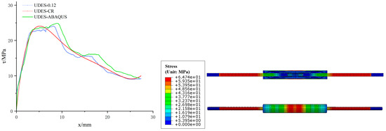
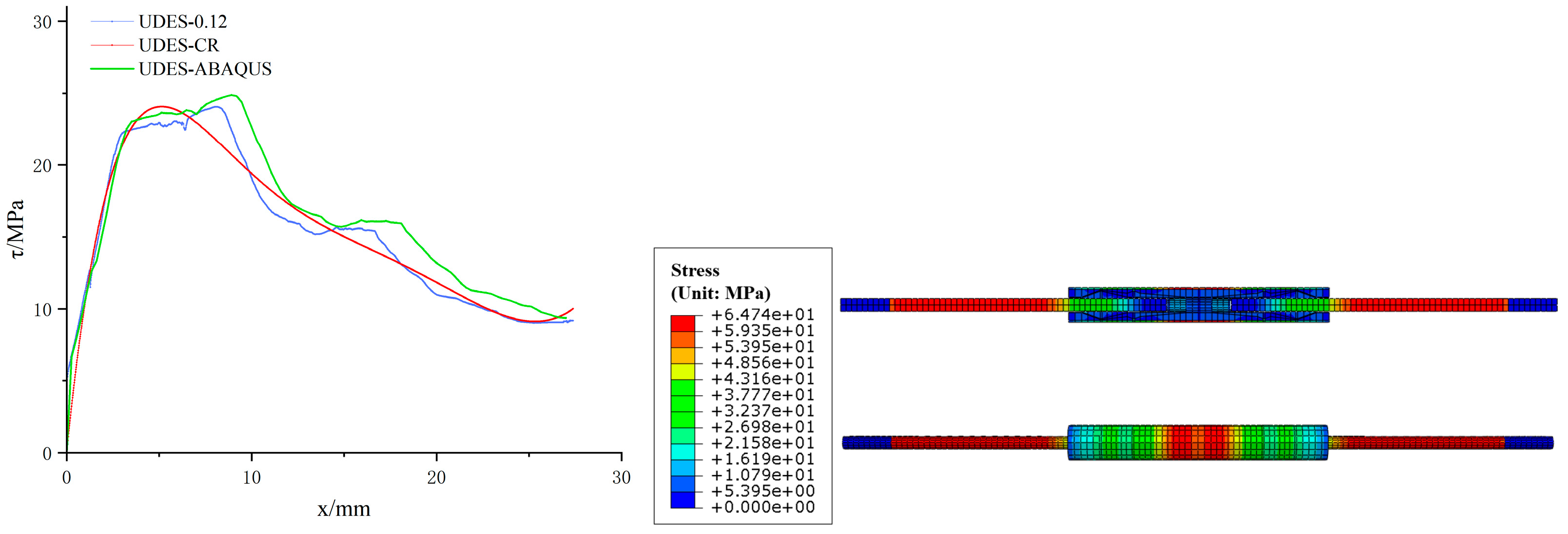
The bond–slip responses from finite element analysis for specimens with multiple defects remain highly consistent in trend with both experimental curves and the fitted constitutive relationship curves (Figure 18). The distinctive features observed in these curves correspond to the rapid interfacial degradation mechanism induced by distributed defects, and faithfully reproduce the associated stress evolution under this condition. The simulation accurately captures the interfacial failure characteristics typical of multiple defects: the ascending-branch stiffness is markedly higher than in other scenarios, exhibiting a steep rise that aligns with the test curve, reflecting accelerated bond-stress accumulation due to the reduced effective anchorage length. The peak bond stress of 24.06 MPa is reached at a slip of approximately 8.09 mm, with close agreement between simulated and measured values (deviation < 4%). And the curve undergoes a rapid post-peak drop, accurately representing the sharp stress decline following complete interfacial debonding.
Using ABAQUS-based finite element simulation as the primary tool, this study analyzed the bond slip behavior at the steel grout interface in fully grouted sleeves with varying defect locations. A tripartite comparative framework encompassing the experimentally measured curve, the constitutive fitting curve (CR curve), and the finite element simulation curve (ABAQUS curve) was established. With the standard grout mix (water-to-binder ratio = 0.12) as the reference, the rationality and accuracy of both the finite element and constitutive models were validated for typical scenarios, including the intact condition, individual defect configurations, and the uniformly distributed defect condition.
Across all examined scenarios, the finite element simulation curves align well with the experimental and constitutive fitting curves in terms of overall trend, while the deviations in peak bond stress and corresponding slip remain within an acceptable range. Even under the uniformly distributed defect condition, where the failure mode shifts from tensile fracture to bar pull out, both models accurately capture the underlying interfacial bond slip response, demonstrating their reliable simulation fidelity. The resulting finite element predictions and constitutive model can therefore serve as a quantitative basis for evaluating the bond performance of grouted sleeve connectors subjected to different defect configurations in practical engineering applications.
7. Conclusions
In this study, 15 specimens of fully grouted sleeve connectors were subjected to central tensile tests, with a focus on evaluating the effects of grouting defect location, defect quantity, and grout water-to-binder ratio on the interfacial slip and bond stress between the reinforcing bar and the grout. The primary conclusions are summarized as follows:
(1) The location of a single grouting defect exhibits limited influence on the failure mode and load-carrying behavior of the connector. For specimens containing an isolated defect, the interfacial bond stress, ultimate load, and corresponding slip are comparable across the three defect locations (end, middle, and top). Moreover, the bond stress versus slip response in all three cases can be described by a unified constitutive model.
(2) The number of grouting defects significantly affects both the failure mode and structural performance. Specimens with a single defect consistently failed by tensile fracture of the reinforcing bar, whereas those with multiple defects underwent bar pull-out failure and exhibited the lowest ultimate load. The abrupt increase in bond stress observed under multiple defect conditions is not attributable to enhanced load capacity, but rather results from the elevated bond force per unit area due to reduced effective anchorage length, after which bond stress progressively declines.
(3) Grout strength demonstrates a positive correlation with interfacial bond performance. The optimum performance corresponds to the standard water to binder ratio of 0.12. Any deviation from this ratio reduces grout strength, which in turn leads to a synchronous decrease in interfacial bond stress, ultimate load, and slip capacity.
(4) The sixth-order polynomial bond slip constitutive model, calibrated with experimental data and implemented in ABAQUS finite element simulations, accurately reproduces the interfacial stress response under various defect conditions. This model not only provides a theoretical foundation for performance assessment and defect mitigation in engineering practice but can also be extended to simulate other loading scenarios, thereby reducing the need for physical testing and associated research costs.
Author Contributions
Conceptualization, W.Z.; methodology, Y.J.; validation, H.G.; formal analysis, W.Z.; investigation, H.G. and Z.X.; data curation, Q.C.; writing—original draft preparation, W.Z.; writing—review and editing, W.Z. and Y.J.; visualization, Q.C. and Y.W.; software, W.Z. and Y.W.; supervision, Y.J.; project administration, W.Z.; funding acquisition, Y.J. All authors have read and agreed to the published version of the manuscript.
Funding
This study was funded by the National University Student Innovation and Entrepreneurship Training Program of College of Civil Engineering and Transportation, Northeast Forestry University, with project number 202410225090. The research topic is Bond–Slip Constitutive Relationship at the Interface between Reinforcement and Grout in Fully Grouted Sleeve Couplers.
Data Availability Statement
The data supporting the results of this study comes from a questionnaire survey and can be obtained from the corresponding author.
Acknowledgments
We would like to express our gratitude to Northeast Forestry University for providing financial support for this research and also thank the anonymous reviewer for their valuable feedback on the original submission.
Conflicts of Interest
The authors declare no conflicts of interest. The funders had no role in the design of the study; in the collection, analyses, or interpretation of data; in the writing of the manuscript; or in the decision to publish the results.
Abbreviations
The following abbreviations are used in this manuscript:
| UTM | Universal Testing Machine |
| NDS | No Defect Specimen |
| EDS | End Defect Specimen |
| CDS | Central Defect Specimen |
| TDS | Top Defect Specimen |
| UDES | Uniformly Distributed Defects Specimen |
| CR | Constitutive Relationship |
References
- Chen, D.; Peng, S.; Hui, Y.; Tam, V.W.Y.; Wang, W.; Li, L.; Cheng, B. Post-fire mechanical properties of full-grouted sleeve connection with different grouting defects. Case Stud. Constr. Mater. 2024, 21, e03616. [Google Scholar] [CrossRef] [Scilit]
- Zhang, Z.; Li, J.; Dai, S.; Guo, J. Mechanical grouting sleeve of rebars: Experimental investigations. Trans. Can. Soc. Mech. Eng. 2024, 48, 302–309. [Google Scholar] [CrossRef] [Scilit]
- Barton, R.D.; Ameli, M.J.; Pantelides, C.P. Precast Concrete Bridge Column-Footing Connections with Recessed Grouted Splice Sleeve Connectors. ACI Struct. J. 2022, 119, 215–226. [Google Scholar] [CrossRef] [Scilit]
- Chen, J.; Wang, Z.; Liu, Z.; Ju, S. Experimental investigation of mechanical behaviour of rebar in steel half-grouted sleeve connections with defects in water/binder ratio. Structures 2020, 26, 487–500. [Google Scholar] [CrossRef] [Scilit]
- Einea, A.; Yamane, T.; Tadros, M.K. Grout-filled pipe splices for precast concrete construction. PCI J. 1995, 40, 82–93. [Google Scholar] [CrossRef] [Scilit]
- Gao, Q.; Zhao, W. Experimental study on factors influencing the connection performance of grouted welded sleeves under uniaxial tensile loads. J. Build. Eng. 2021, 43, 103033. [Google Scholar] [CrossRef] [Scilit]
- Henin, E.; Morcous, G. Non-proprietary bar splice sleeve for precast concrete construction. Eng. Struct. 2015, 83, 154–162. [Google Scholar] [CrossRef] [Scilit]
- Ling, J.H.; Rahman, A.B.A.; Ibrahim, I.S.; Hamid, Z.A. Tensile capacity of grouted splice sleeves. Eng. Struct. 2016, 111, 285–296. [Google Scholar] [CrossRef] [Scilit]
- Lu, Z.; Huang, J.; Li, Y.; Dai, S.; Peng, Z.; Liu, X.; Zhang, M. Mechanical behaviour of grouted sleeve splice under uniaxial tensile loading. Eng. Struct. 2019, 186, 421–435. [Google Scholar] [CrossRef] [Scilit]
- Zheng, Y.; Guo, Z.; Guan, D.; Zhang, X. Parametric study on a novel grouted rolling pipe splice for precast concrete construction. Constr. Build. Mater. 2018, 166, 452–463. [Google Scholar] [CrossRef] [Scilit]
- Liu, L.; Xiao, J.; Ding, T.; Zhang, K. Experimental and Simulation Analysis of the Bonding Performance between Sleeve Grouting Material and High-strength Steel Reinforcement. J. Tongji Univ. (Nat. Sci. Ed.) 2021, 49, 1275–1283. [Google Scholar] [CrossRef]
- Xu, T.; Li, Q.; Zhao, R.; Ding, J.; Zhan, Y. On the early-age bond-slip behavior of an eccentric bar embedded in a grouted sleeve. Eng. Struct. 2019, 190, 160–170. [Google Scholar] [CrossRef] [Scilit]
- Al-Jelawy, H.M. Experimental and numerical investigations on monotonic tensile behavior of grouted sleeve couplers with different splicing configurations. Eng. Struct. 2022, 265, 114434. [Google Scholar] [CrossRef] [Scilit]
- Feng, Q.; Zheng, S.; Wang, Y.; Xiang, H.; Wang, J.; Xu, R. Failure mechanism analysis and partial-interaction numerical simulation of Grouted Sleeve Connections (GSC) in tensile behavior. Case Stud. Constr. Mater. 2024, 20, e03040. [Google Scholar] [CrossRef] [Scilit]
- Zhao, Y.; Zhang, H.; Pan, Z.; Li, G. Mechanical behavior of grouted sleeve connection for rebars in precast concrete structures and reliability analysis considering the ratio of anchorage length to rebar diameter. Case Stud. Constr. Mater. 2024, 20, e02883. [Google Scholar] [CrossRef] [Scilit]
- Shang, A.; Li, Y.; Zhang, H.; Dai, Y.; Zhou, M. Study on the Detection of Sleeve Grouting Defects Using the Impact-Echo Method: FEM and Experimental Analysis. Appl. Sci. 2025, 15, 11813. [Google Scholar] [CrossRef] [Scilit]
- Lang, S.; Yan, X.; Song, X.; Zhang, Z. Experimental investigation and refined finite element analysis of the tensile performance of grouted sleeve connections. Structures 2026, 87, 111530. [Google Scholar] [CrossRef] [Scilit]
- Espoir, K.K.; Fuzhe, X.; Lu, C.; Offei, I. Experimental and numerical assessment of the location-based impact of grouting defects on the tensile performance of the fully grouted sleeve connection. Frat. Integrita Strutt. 2022, 16, 437–460. [Google Scholar] [CrossRef] [Scilit]
- Li, Q.; Yi, M.; Zhang, B. Mechanical properties of grouted sleeve splice with horizontal grouting defect after exposure to high temperature. Structures 2025, 79, 109443. [Google Scholar] [CrossRef] [Scilit]
- Ren, H.; Liu, Y.; Huang, T.; Xu, W.; Chen, D. Mechanical properties of full-grouted sleeves with grouting defects. J. Asian Archit. Build. Eng. 2023, 22, 3552–3568. [Google Scholar] [CrossRef] [Scilit]
- Yang, S.; Qiao, Q.; Liu, W.; Jia, R.; Cao, W. Experimental study on cyclic tensile performance of half-grouted sleeve connections with various grouting defects. Constr. Build. Mater. 2025, 500, 144139. [Google Scholar] [CrossRef] [Scilit]
- Zhang, X.; Cao, Y.; Liu, S.; Zhang, Z.; Xu, X.; Gao, P.; Zhou, J. Experimental study on seismic performance of prefabricated bridge pier joints with half-grouted sleeve and socket composite connections. Structures 2026, 87, 111495. [Google Scholar] [CrossRef] [Scilit]
- Leibovich, O.; Yankelevsky, D.Z. Bond behavior in pull-out of a ribbed rebar from concrete with recycled concrete aggregates. Case Stud. Constr. Mater. 2022, 17, e01607. [Google Scholar] [CrossRef] [Scilit]
- Guo, T.; Yang, J.; Wang, W.; Li, C. Experimental investigation on connection performance of fully-grouted sleeve connectors with various grouting defects. Constr. Build. Mater. 2022, 327, 126981. [Google Scholar] [CrossRef] [Scilit]
- Chen, D.; Wu, Z.; Bao, Y.; Ding, S.; Shao, Y.; Xu, T. Experimental Study on Mechanical Properties of Half-Grouted Sleeve Connections with Grouted Defects. Buildings 2022, 12, 1807. [Google Scholar] [CrossRef] [Scilit]
- Li, Q.; Tian, Y.; Fang, D.; Zhao, K.; Chen, H.; Jin, X.; Fu, C.; He, R. The influence of longitudinal rebar type and stirrup ratio on the bond performance of reinforced concrete with corrosion. Constr. Build. Mater. 2023, 409, 133943. [Google Scholar] [CrossRef] [Scilit]
- Islam, K.; Billah, A.M.; Chowdhury, M.M.I.; Ahmed, K.S. Exploratory study on bond behavior of plain and sand coated stainless steel rebars in concrete. Structures 2020, 27, 2365–2378. [Google Scholar] [CrossRef] [Scilit]
- Li, X.; Wu, Z.; Zheng, J.; Yu, R.C.; Zhou, X. Effect of loading rate on the bond behaviour of plain round bars in concrete subjected to uniaxial lateral tension. Mag. Concr. Res. 2021, 73, 1033–1047. [Google Scholar] [CrossRef] [Scilit]
- Shi, H.; Li, H.; Wang, Z.; Huang, F.; Yang, Z.; Wen, J.; Dong, H.; Yi, Z. Bond-slip behaviour between recycled sand concrete and steel bars. J. Build. Eng. 2024, 86, 108980. [Google Scholar] [CrossRef] [Scilit]

Disclaimer/Publisher’s Note: The statements, opinions and data contained in all publications are solely those of the individual author(s) and contributor(s) and not of MDPI and/or the editor(s). MDPI and/or the editor(s) disclaim responsibility for any injury to people or property resulting from any ideas, methods, instructions or products referred to in the content. |
© 2026 by the authors. Licensee MDPI, Basel, Switzerland. This article is an open access article distributed under the terms and conditions of the Creative Commons Attribution (CC BY) license.