


Abstract
Recycled aluminum has emerged as an excellent alternative for producing new alloys. The development of multicomponent alloys has led to products with enhanced properties, and the aluminum alloy market has increased. This study utilized squeeze casting to produce Al alloy samples. The effects of 5 wt.% of both the Si content and the Al-25.5 Cu−12 Fe quasicrystal (QC) content on the microstructural formation and microhardness analyzed. A cellular microstructural formation was found for the recycled aluminum. A dendritic structure was characterized in both the Alrec−5% Si and Alrec−5% QC alloys. After adding 5% wt.% QCs, the resulting hardness became higher (varying between 110 and 130 HV) than the alloy with 5 wt.% Si (90 and 110 HV) and the recycled aluminum alloy (between 70 and 80 HV). The portion of the QC alloy completely dissolved into the bulk of the recycled alloy during squeeze casting. This was associated with a more complex phase arrangement characterized by the QC alloy. This was characterized by a dendritic microstructural array with binary eutectic mixtures (α-Al + Mg2Si) and refined ternary eutectic mixtures (α-Al + Mg2Si + AlFe(Si)). In contrast, the sample with Si content and the recycled alloy sample without additions depicted resulting microstructural arrays with reduced secondary phase formations. These contributed to improved mechanical behavior through traditional strengthening mechanisms.
1. Introduction
Aluminum is one of the most widely recycled materials globally, primarily through casting processes that produce low-cost components or by being extruded or rolled into new aluminum cans. The recycling of aluminum not only conserves energy and resources, but also allows for the development of high-strength alloys. These alloys can serve as matrices for the production of structural components used in critical applications, such as applications in the aerospace and automotive industries. Despite its popularity, aluminum has inherent limitations in its mechanical strength and hardness. However, these properties can be significantly enhanced through the addition of alloying elements. For instance, silicon (Si) is commonly added to improve fluidity during casting, increase the corrosion resistance, and decrease the overall weight of the material. Quasicrystals (QCs) represent a novel class of metallic materials.
Shechtman et al. first discovered QCs in 1984 [1]. These materials stand apart from conventional solids—whether amorphous or crystalline—due to their unique structural characteristics, which give rise to exceptional properties [1]. While they are well ordered, QCs do not repeat at regular intervals. In other words, they lack long-range periodicity, which is why they are classified as quasiperiodic structures. QCs are composed of structural units with unusual symmetries, such as icosahedra, octagons, decagons, or dodecagons, rather than the typical unit cells found in conventional crystals [2,3]. Their key characteristics include a low friction coefficient about one-third that of carbon steel and a surface energy only 25 to 30% higher than that of Teflon, along with being hard, brittle, and highly resistant to corrosion [4]. Due to these remarkable properties, QCs are primarily utilized as coatings or as reinforcement in composite materials. The brittleness of QCs at room temperature is mitigated by their matrix or the substrate material in which they are embedded.
In recent years, quasicrystals have emerged as a promising area in materials science. These unique structures exhibit a range of desirable properties, including a high hardness, a low electrical and thermal conductivity, a low friction coefficient, a low surface energy, and an exceptional corrosion resistance. They also possess unique optical characteristics not found in conventional crystalline alloys [5,6,7]. Due to these properties, QC (quasicrystalline) alloys are gaining interest for a variety of applications, such as structural materials, thermal and electrical systems, coatings, and anti-corrosion solutions.
The automotive and aerospace industries demand structural materials that offer a combination of a high-temperature strength, a low density, and excellent corrosion resistance. These stringent requirements along with cost considerations have driven the development and adoption of advanced technologies for producing multicomponent aluminum alloys [5,6,7,8]. Among the lightweight materials, Al–Mg–Si alloys are particularly promising due to their favorable chemical and mechanical properties [8,9,10,11]. In these alloys, the formation of Mg2Si particles plays an important role, and the common presence of iron impurities leads to additional particle precipitation during solidification [12]. The microstructure of the Al–Mg–Si alloys, specifically the morphology of the Al-rich matrix and the distribution of secondary phases, is highly dependent on the cooling rate during solidification [13,14]. Theoretical and experimental studies on directional solidification have shown that, under near-equilibrium conditions, the solid/liquid interface transitions from planar to cellular, and then to dendritic, as the growth rate (VL) increases. This clearly reveals the direct influence of the solidification parameters on the morphology of the solidification front.
Squeeze casting is a modern manufacturing process that has demonstrated improvements across various performance parameters when conscientiously applied. This technique is viewed as a hybrid of casting and forging [15]. It involves applying pressure to the molten metal throughout the solidification stage [16]. Over the past four decades, the effects of the pressure-assisted solidification on the casting properties have been extensively studied [17]. Vijian and Arunachalam [18,19] and Yu et al. [20] revealed that, by pressurizing the molten component in the solidification, the melting point of the alloy is modified. This accelerates solidification and refines both the microstructure and macrostructure; consequently, a significant decrease in the shrinkage porosity is attained.
In the present study, a multicomponent alloy based on recycled aluminum (Al-Mg-Si) was investigated, with additions of silicon (Si) and QC materials (with a close composition at Al−25.5 Cu−12 Fe). The alloy was solidified under pressure using squeeze casting, under unsteady-state solidification conditions. The novelty of this present investigation concerns the effects of adding 5 wt.% Si and 5 wt.% quasicrystals (QCs) on the solidification microstructure of the recycled aluminum. These additions affected the formation of intermetallics and secondary phases, and consequently substantially modified the resulting microhardness.
2. Materials and Methods
Recycled aluminum was used to prepare the alloys. Table 1 depicts their resulting chemical composition. The recycled aluminum originated from soda and beer cans, which were melted inside the chamber of a furnace (muffle type, 6KVA, Fortlab, São Paulo, SP, Brazil). The specimens were melted inside of cylindrical molds of 100 × 30 (±1.5) mm. Subsequently, the samples were cut and weighed.
Table 1.
X-ray fluorescence spectrometry analyses demonstrating the chemical composition (*) of the recycled aluminum alloy and the QC alloys (**).
The QC alloys were initially melted in an open induction furnace (INDUTHERM MU 400, INDUTHERM Erwärmungsanlagen GmbH, Walzbachtal, Germany) without gas protection. The molten metal was first cast into a permanent low-carbon steel mold (SAE 1020). To achieve this in the target stoichiometric composition of the Al−25.5 Cu−12 Fe alloy, a compensation step was performed using a 10 g charge of the Al-Fe alloy, which was melted inside an induction furnace under an argon atmosphere. Following this adjustment, copper was added to the melt to reach the desired final composition. The final casting was performed using a 45 (±1.5) g molten charge. The induction furnace was operated at 4 kW of power and a temperature of 1300 (±5) °C. Subsequently, the alloy was poured at the same temperature. The chemical composition of the utilized QC alloy is also shown in Table 1. Additionally, it is remarked that both the X-ray Diffraction (XRD) patterns and the resulting microstructure of the QC alloy have been previously reported [21]. It is also remarked that these results were not demonstrated in this study due to only a portion of the QC alloy being added into the recycled alloy. Consequently, the majority elements were dissolved into an Al-rich matrix or they constituted other AlFeCu intermetallics, as will be discussed. Similar microstructures are also reported [22,23].
After obtaining the recycled aluminum (AlRec) and the QC alloy, two compositions were prepared: the AlRec–5 wt.% Si and AlRec –5 wt.% QC. From this moment, these alloys are denoted as AlRec–5%Si and AlRec–5%QC. The alloys were melted inside an electric muffle furnace (6KVA, FortLab, São Paulo, SP, Brazil) at 900 (±5) °C. Subsequently, the molten alloys were poured into a permanent steel mold. During the liquid state (melting stage), a pressure of 100 MPa was applied for 10 s.
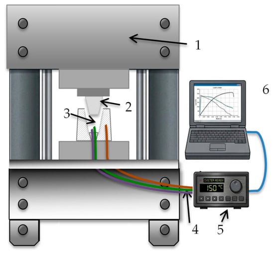
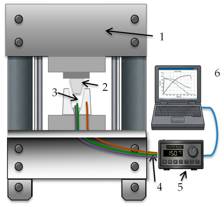
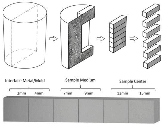
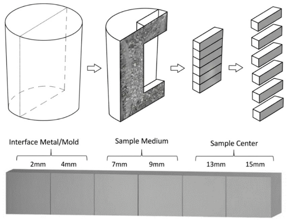
A schematic representation of the experimental setting is shown in Figure 1. For each one of the produced ingots, a longitudinal cut was initially carried out. This procedure was followed by transverse cuts in semicircle shapes with a thickness of 10 (±1) mm. A total of eight (08) discs per ingot were produced. For the macro- and microstructural characterizations, the first and last discs were excluded.
Figure 1.
Schematic representation of the experimental solidification of squeeze casting: (1) hydraulic press with control; (2) pulsation; (3) cylindrical mold; (4) thermocouples; (5) temperature recorder (data logger); and (6) computer and data acquisition software.
This is because these regions correspond to the upper pulsation and the lower sealing devices, where the radial heat extraction takes place. For the analysis, only 6 discs from each ingot were utilized. For the characterization of the resulting microstructural arrays and microhardness, the average values were taken from positions that were 4 mm and 12 mm from the metal/mold interface, as depicted in Figure 2.
Figure 2.
Schematic representation showing the positions of the selected samples to carry out the examinations and characterization.
For the characterization of the resulting microstructural arrays, a 0.5% hydrofluoric acid (HF) solution during the interval between 10 and 30 s was used. Image-processing systems utilizing the Neophot 32 (Carl Zeiss, Esslingen, Germany) and the Leica Quantimet 500 MC (Leica Imaging Systems Ltd., Cambridge, UK) were used. With these, the measurements of both the cellular and dendritic arm spacing formations were carried out. The method used for determining the dendrite arm spacing followed a previously reported procedure [20].
For the XRD analysis, the samples were selected from the central region of the ingot. This region is considered the best for the representation of a possible variation in cooling rates along each analyzed ingot. The measurements were performed to determine the phase composition forming the microstructure of each alloy as a function of the position. A Shimadzu XRD−7000 diffractometer (Department of Materials Engineering–Federal University of Paraíba, João Pessoa, PB, Brazil) within a 2θ range from 20° to 90°, using Cu-Kα radiation with a wavelength (λ) of 0.15406 nm, was used. This was used to characterize the crystallography of the examined alloys.
Vickers microhardness measurements using a Shimadzu HMV−2 hardness tester (Shimadzu, Barueri, SP, Brazil) at an environmental temperature (at 24 ± 2 °C) were carried out. The measurements considered a loaf of 200 g (0.2 kgf) and a dwell time of 15 s. The average values were obtained from the 20 individual measurements. This reasonably guaranteed the reproducibility and repeatability of the experimentation carried out.
3. Results and Discussion
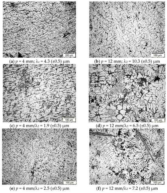
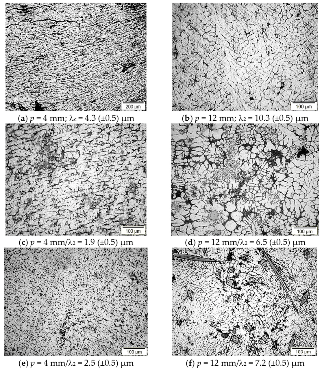
The resulting typical microstructural morphologies of the AlRec, AlRec–5%Si, and AlRec–5%QC alloys are shown in Figure 3a–f. These correspond with two distinct positions: the first was located 4 mm from the metal/mold interface and the other was 12 mm from the center of the ingot. In the case of the AlRec alloy sample, a cellular microstructural array was clearly characterized. This was located at the 4 mm position, and the observed cells exhibited an elongated shape. Closer to the center, at the 12 mm position, the microstructural transitions to a dendritic morphology were revealed.
Figure 3.
Typical microstructures of the (a,b) AlRec, (c,d) AlRec–5%Si, and (e,f) AlRec–5%QC alloy samples, respectively.
The AlRec–5%Si alloy sample showed a predominantly dendritic microstructure formation. This occurred from the outer region to the center of the ingot. A similar dendritic arm spacing formation was also characterized for the AlRec–5%QC alloy sample. Additionally, for the AlRec–5%QC alloy, plate-like AlFeMn phases with a diamond-shaped morphology were observed. This occurred predominantly and substantially close to the central region of the ingot.
According to Mondolfo [24], when the magnesium content in an Al-Mg alloy is lower than 17.4% at 723 K (~450 °C), there exists the possibility of a single-phase α-Al to be formed, especially considering equilibrium or close-to-equilibrium cooling conditions. Both the cooling rate and the nominal composition affect the segregation and the tendency to form the second phases. In this study, the AlRec alloy sample solidified under pressure, and the optical images (shown in Figure 3) suggest that the secondary phases were discretely constituted and located at α-Al dendrite boundaries.
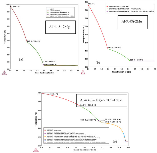
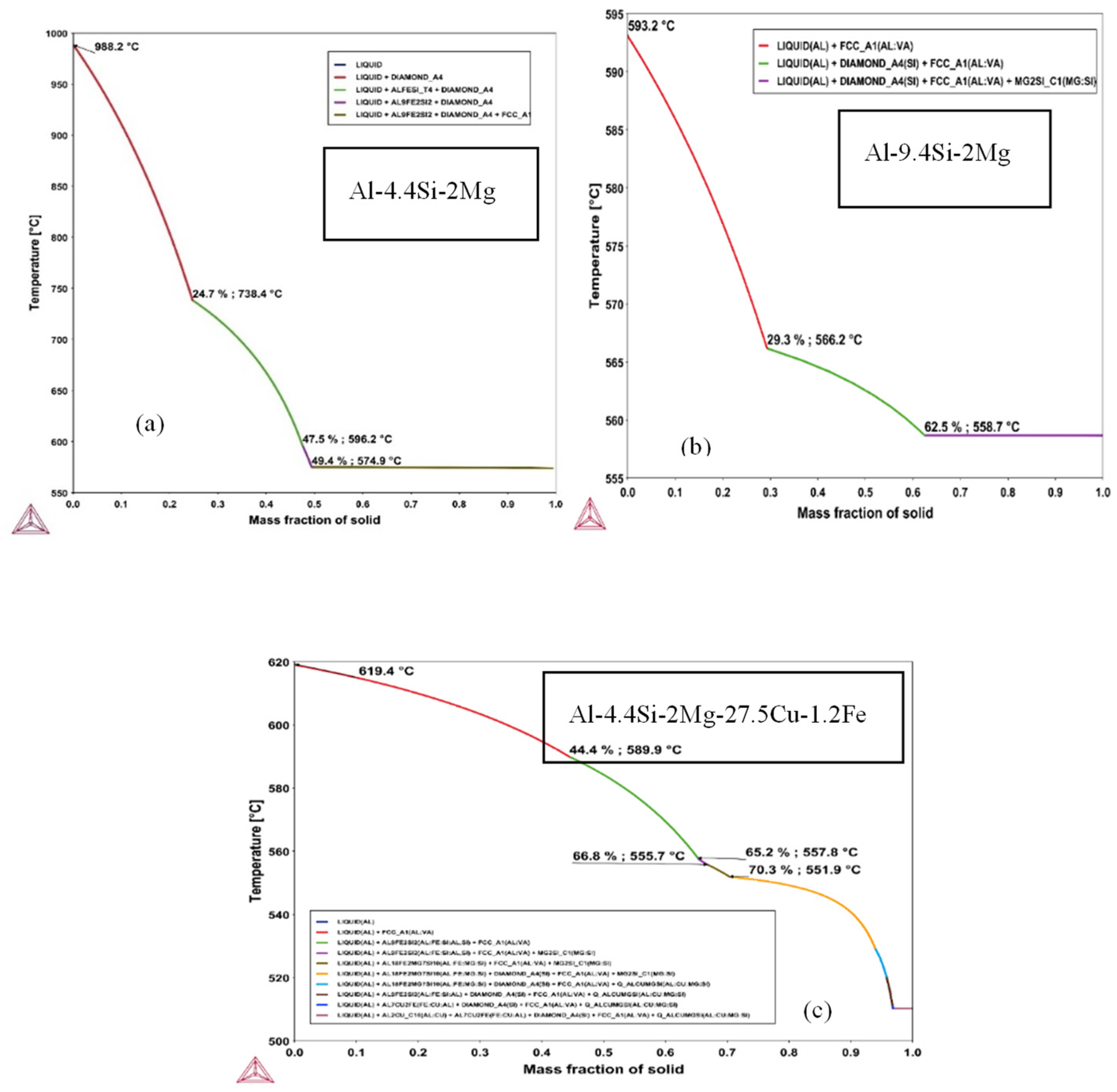
ThermoCalc® computations of the solidification path of three distinct ternary Al-Si-Mg alloys are shown in Figure 4a–c. The presence of impurities such as iron and silicon was identified, i.e., 0.15 wt.% Fe and 0.15 wt.% Si. Kumar et al. [13] identified this in an as-cast Al-Mg alloy (strip), with their findings in agreement with the observations of the present study. The growth of α-Al, the Mg-Si-rich phase, and Fe-bearing intermetallics were also characterized.
Figure 4.
Solidification paths calculated by the Thermo-Calc® software, version 4, Stockolm, Sweden, of the (a) AlRec alloy; (b) AlRec–5%Si alloy; and (c) AlRec–5% QC alloy.
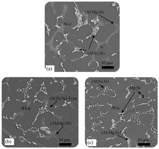
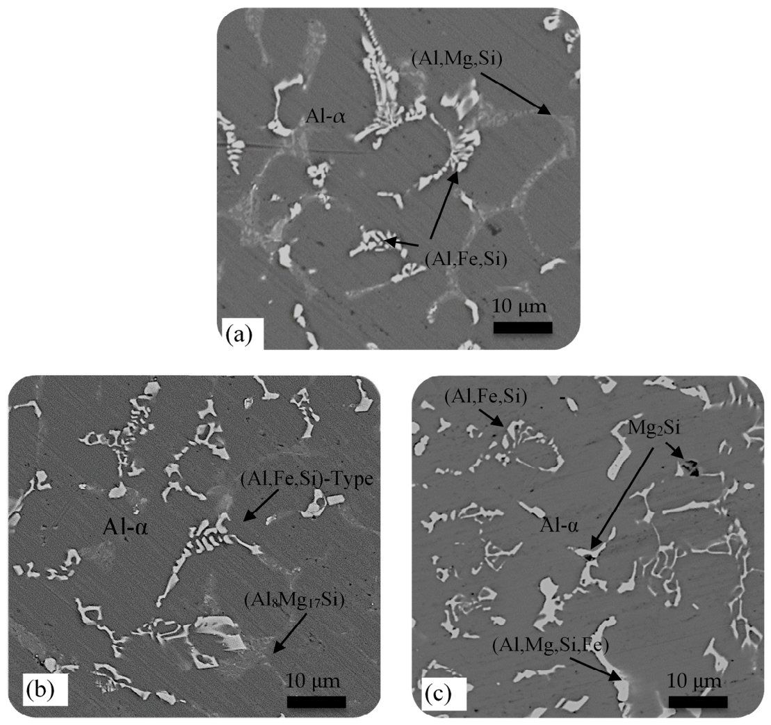
The solidification path under equilibrium conditions for the Al-Mg alloys was relatively simple, and the final solidification microstructure consisted basically of the α-Al phase. On the other hand, in the Al-Mg-Si alloys, the magnesium and silicon contents were lower than 2% and 1%, respectively. This promoted a resulting microstructural array that was somewhat more complex, as reported by Kaygisiz and Marasli [9]. The solidification of these alloys under transient heat extraction conditions induced the formation of unpredicted phases. These corresponded with phase diagrams, especially when a minor content of Fe was present. In the case of the AlRec alloy sample, α-Al, primary silicon with a diamond_A4 crystal structure and iron-rich intermetallic phases (Al9Fe2Si2) were characterized. These were homogeneously dispersed and embedded into the Al-rich matrix. When the AlRec –5%Si alloy sample was analyzed, a microstructural formation indicated that, under non-equilibrium solidification conditions, the expected phases were α-Al, Al-Mg-β (Al3Mg2), and Mg2Si. Nevertheless, the increased silicon content promoted the formation of a distinct crystalline silicon phase with a diamond-type structure, as shown in Figure 4b. Figure 4c depicts the solidification path of the AlRec–5%QC alloy sample and a residual of 0.60 wt.% Fe content. Under non-equilibrium conditions, the observed phases included Al-α, Al9Fe2Si2, Al18Fe2Mg7Si10, Al7Cu2Fe, Mg2Si, and a complex intermetallic phase, probably with an AlMgCuSi composition. The typical experimental SEM mapping results of the multicomponent AlRec alloy, AlRec–5%Si alloy and AlRec–5% QC alloy are shown in Figure 5a, Figure 5b and Figure 5c, respectively. All of the observed micrographs evidence the eutectic formation, i.e., the α-(Al) + Si + π-AlMgFeSi + θ-Mg2Si mixture into the interdendritic region. Basically, a gray background α-Al matrix is characterized by darker spots where the Mg2Si intermetallic prevails and lighter phases are identified as the AlFe(Si) type.
Figure 5.
Typical SEM micrographs showing the phases formed during radial pressure solidification of the as-cast alloys: (a) AlRec alloy, (b) AlRec–5%Si alloy and (c) AlRec–5% QC alloy samples located at the central position of the ingot.
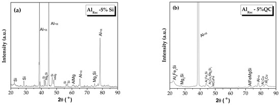
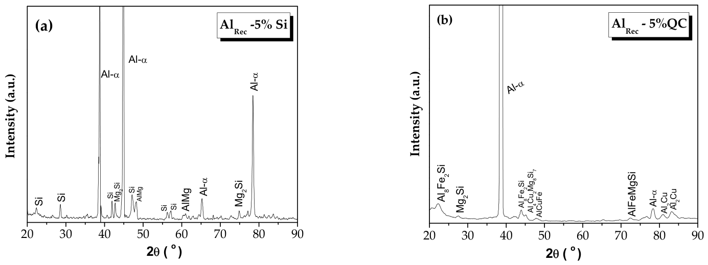
Figure 6a and Figure 6b show the resulting XRD analysis of the AlRec–5%Si and AlRec–5% QC alloys samples, respectively. Figure 6a shows the peak intensity corresponding to Al at 2θ ~44.7°, which is substantially occluded. It is worth noting that 38.5° corresponds to the highest-intensity peak related to Al. This seems to be associated with a preferential orientation (crystallography texture). It was determined that, due to the squeeze casting applied, the Al-matrix dendrites were refined, as is demonstrated below. Also, due to Fe dissolution at 900 °C, after solidification, it precipitated as complex intermetallics. Additionally, minor Cu and Mg contents tended to react with Si during the squeezing casting. Consequently, fine Al2Cu was formed, and possibly complex Al4Cu2Mg8Si7 (lath-like), AlFeSi, AlFeMgSi and Mg2Si at interdendritic regions were precipitated, as identified from the XRD pattern results shown in Figure 6.
Figure 6.
Typical X-ray diffraction (XRD) patterns: (a) AlRec–5%Si alloy and (b) AlRec–5% QC alloy samples. The JCPDS file numbers were #00−001−1180 (for Al) data from [25], #01−1180 (for Al2Cu) [25], #26−1481 (for Si) data from [25,26], #034−0458 (for Mg2Si) data from [26], and #71−0238 (for AlFeSi) data from [27].
It is important to remark that the Si peaks of the AlRec–5% QC alloy sample were completely occluded from the AlFeSi intermetallic formations. For instance, close to ~22° and ~42°, the Si peaks were not characterized due to the Al8Fe2Si being formed. A higher intensity with a large base was verified, which possibly incorporated Si to constitute this specific intermetallic formation. A similar situation occurred at 28°, due to the Mg2Si formation, and close to 48° due to the formation of Al4CuMg8Si7. This stoichiometry showed a high Si content in its composition.
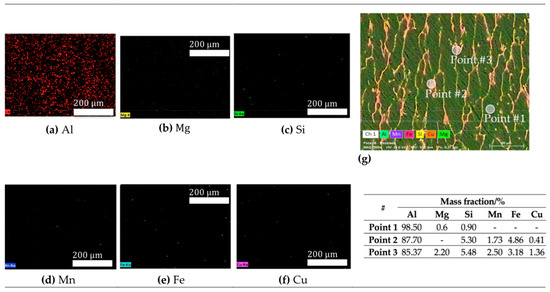
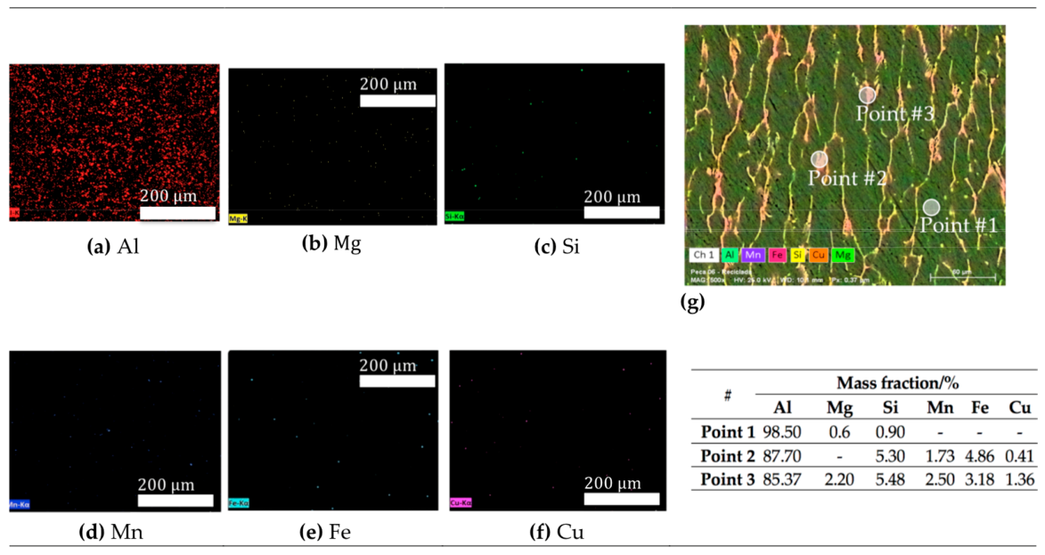
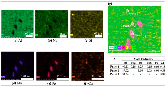
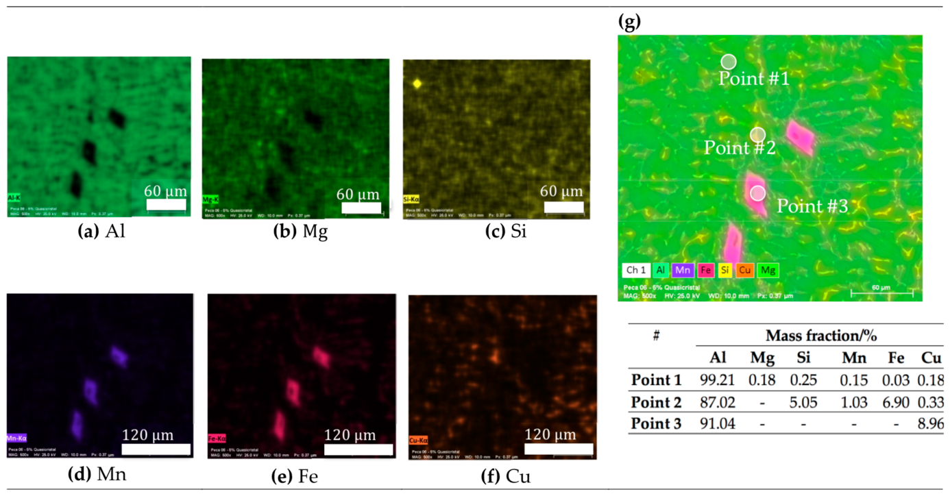
The typical SEM microstructural arrays of the examined alloys are shown in Figure 7, Figure 8 and Figure 9. The micrographs of the recycled aluminum (AlRec), recycled aluminum with the 5% silicon addition (AlRec−5%Si), and recycled aluminum with the 5 wt.% QC addition (AlRec−5%QC) are depicted in Figure 7, Figure 8 and Figure 9, respectively. The resulting α-Al matrix, the primary Al2Cu phases, and the intermetallic compounds containing Fe and Mn, predominantly located at the dendritic boundaries, are predominantly characterized, as also previously reported [18,19,24,28,29]. In Figure 7, the AlRec alloy displays an aluminum-rich matrix with a chemical composition of 98.5% aluminum with minor Mn and Si contents in the Al-rich matrix. While aluminum clearly constitutes the primary matrix, the elements Mg and Si are primarily concentrated along the grain boundaries, which suggests segregation during solidification. Figure 7a,b,c show elemental maps corresponding with individual elements, i.e., Al, Mg, and Si, while Figure 7d,e and f show the maps for Mn, Fe and Cu, respectively. Figure 7g shows the elemental map with the cellular microstructural array followed by its chemical compositions at three different points: #1, #2 and #3. Additionally, it can be observed that points 2 and 3 are located at the grain boundaries, and these have a high aluminum content (85.37 wt.%). These also indicate the significant segregation of other elements, as depicted. This supports the previously mentioned indication of elemental segregation occurring during the solidification process.
Figure 7.
SEM/EDS images of the examined AlRec alloy located at the central position of the ingot, showing the elemental maps of (a) Al, (b) Mg, (c) Si, (d) Mn, (e) Fe and (f) Cu. Cellular microstructure array with the EDS elemental distribution (g) and its corresponding chemical composition is depicted. The hash symbol refers to the number of points analyzed.
Figure 8.
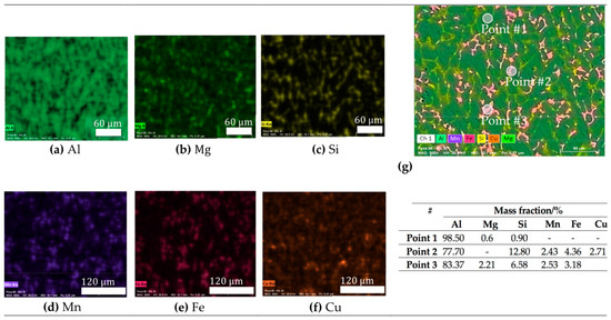
SEM/EDS images of the examined AlRec−5%Si alloy sample located at the central position of the ingot, showing the elemental maps of (a) Al, (b) Mg, (c) Si, (d) Mn, (e) Fe and (f) Cu. Resulting dendritic microstructure array with the EDS elemental distribution (g) and its corresponding chemical composition is depicted. The hash symbol refers to the number of points analyzed.
Figure 9.
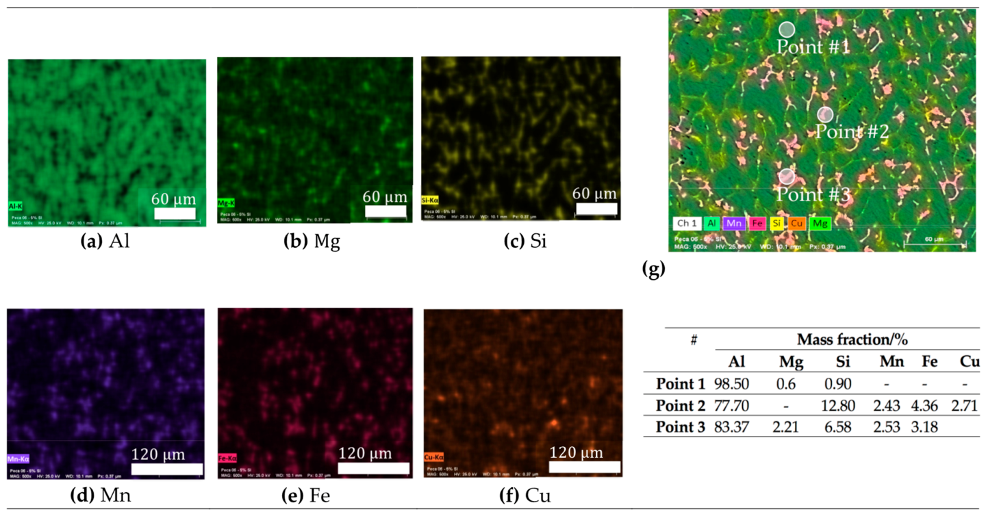
SEM/EDS images of the examined AlRec–5%QC alloy located at the central position of the ingot, showing the elemental maps of (a) Al, (b) Mg, (c) Si, (d) Mn, (e) Fe and (f) Cu. Dendritic microstructural array with the EDS elemental distribution (g) and its corresponding chemical composition is depicted. The hash symbol refers to the number of points analyzed.
Figure 8 depicts the AlRec−5%Si alloy exhibiting a microstructure characterized by an aluminum matrix containing the α-Al phase. Figure 8a–f depict the resulting individual elemental maps corresponding with Al, Mg, Si, Mn, Fe and Cu, while the dendritic microstructure formation with three distinctive analysis points is depicted in Figure 8g with its chemical compositions below. Variation in the elements within the microstructure was observed. Due to the tendency of silicon atoms to segregate and form clusters, when the concentration of Si was rejected from the Al matrix, it surpassed the eutectic composition, and the primary Si phase precipitated alongside the α-Al phase, as previously reported [30]. Using energy-dispersive X-ray spectroscopy (EDS), two distinct points were analyzed. At point 1, located within the matrix, an Al-rich region was revealed. This indicated the presence of the primary α-Al phase. Points 2 and 3, located at the grain boundaries, indicated a complex structure containing Al, Mg, Mn, Si, Cu, and Fe. This suggested the formation of the intermetallic compounds.
Figure 9 shows a typical AlRec−5%QC alloy, which also constituted a dendritic microstructure formation. Figure 9a–f show elemental maps of Al, Mg, Si, Mn, Fe and Cu, respectively. A dendritic microstructural array is also characterized. Three distinctive analysis points are shown in Figure 9g and its corresponding chemical compositions are demonstrated below. A diamond-shaped morphology is clearly characterized. In multicomponent alloys such as this one, the solidification involves complex thermodynamic interactions and solute interdiffusion. These conditions often lead to the formation of secondary phases and intermetallic compounds during the early solidification stages.
At distinctive points in the microstructure array, the chemical composition of the phases was examined. At point 1, the α-Al–rich phase (matrix) was characterized. At point 2, an intermetallic phase was observed, with a high concentration of iron (8.38 wt.%) and manganese (4.82 wt.%). These elements probably originated from the recycled aluminum alloy. However, the iron content increased due to the addition of the portion (5 wt.%) of the quasicrystalline alloy (Al−25.5 Cu−12 Fe). This characterizes the interdendritic regions, which are neighboring grains constituted by a Si-eutectic formation. When an Al-Si-based alloy is solidified using squeeze casting, similar microstructure characterization is reported [31]. Thus, the resulting microstructure is finer Si particles neighbored by Al-matrix dendrite, as also reported [31]. Combined with the radial solidification process, this promotes the segregation of these elements with aluminum, leading to the formation of the intermetallic Al2Fe3Mn. At point 3, Al2Cu intermetallic formations were characterized as lamellae along the grain boundaries. This shows that the Cu content from the QC alloy was adsorbed after solidification. This promoted its precipitation as intermetallic to “anchorage” for the Al matrix, and consequently, the mechanical behavior increased. It is also remarked that, at point 3, the composition corresponded perfectly with the obtained XRD analysis. Thus, the Al2Cu and Q phases were constituted.
Table 2 demonstrates the results of the EDS and the possible phases identified and compared with the XRD pattern results of the examined AlRec–5%Si and AlRec–5%QC alloy samples at three different points, as shown in Figure 7 (SEM) and Figure 6 (XRD).
Table 2.
Examined Si and AlRec–5%QC samples.
Considering Table 2, it was confirmed that the XRD and EDS results were consistent for both the AlRec–5%Si and AlRec–5%QC alloy samples. When the AlRec–5%QC alloy was analyzed, distinctive AlFeSi, AlCuFe and AlFeMgSi were possibly identified. Their corresponding chemical composition, containing Al (balance) and Cu, Mg, Si, and Fe contents, was verified. It is worth noting that Mn was identified in the EDS results. Commonly, this element is associated with AlFeSi intermetallics and is not detected in XRD analyses. This is associated with common (or typical) limiting detection of the utilized equipment. These verified crystallographic phases are useful for understanding the results of the hardness attained. Also, these are associated with the microstructural formation, as is discussed below.
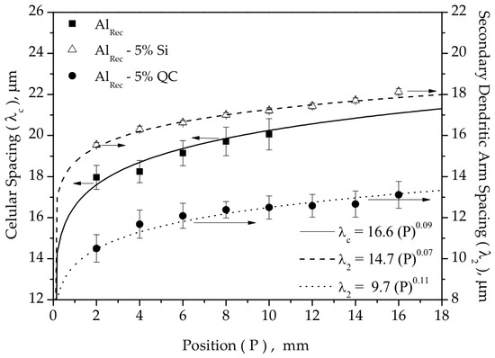
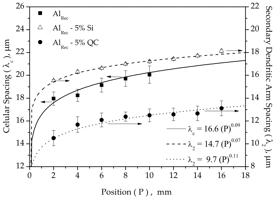
Figure 10 shows the variation in the cellular and dendritic spacings as a function of the distance (p) from the metal/mold interface for the three examined alloy samples. For all of the alloys studied, the microstructural spacing increased with an increase in the distance from the interface. In particular, the AlRec alloy exhibited an increase in the cellular spacing, while both the AlRec–5%Si and AlRec–5%QC alloy samples had their secondary dendritic arm spacings (SDASs) increased.
Figure 10.
Experimental results of the evolution of the cell spacing (λc) and the secondary dendritic spacing (λ2) of the examined alloys as a function of the distance (p) from the metal/mold interface. Arrows indicate the cellular or dendritic microstructures.
Among the modified alloys, the AlRec–5%QC alloy had a considerably lower SDAS than the AlRec–5%Si alloy. This promoted a finer dendritic structure. The unmodified recycled aluminum alloy (AlRec) showed a cellular-to-dendritic transition close to the metal/mold interface, as previously demonstrated.
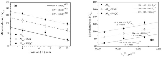
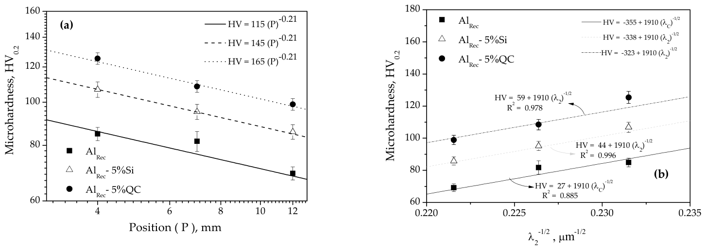
The microhardness (HV0.2) variations with the distance (p or Position) from the metal/mold interface (p), the dendritic arm spacing, and the cooling rate are depicted in Figure 11a. A Hall–Petch-type correlation was proposed, which associates the HV with microstructural spacings. An inverse square root dependence was prescribed, as depicted in Figure 11b. Originally, the Hall–Petch law described the relationship between the yield strength of polycrystalline materials and their grain size. The increase in the strength was attributed to the obstruction of dislocation motion by grain boundaries. However, grains are frequently heterogeneous, often containing different phases and intermetallic compounds that obstruct dislocation motion. As a result, modified Hall–Petch-type relationships have been reported [31,32,33] in order to correlate the tensile properties with other microstructural length scales, such as the interphase boundaries and the dendritic arm spacings. Since hardness involves plastic deformation, and thus, dislocation activity, the hardness of metallic alloys has likewise been found to correlate with microstructural spacings through similar Hall–Petch-type correlations [33,34].
Figure 11.
Experimental correlations between the microhardness with the (a) distance (p) and (b) inverse square root of dendritic spacings.
Figure 11a demonstrates that the microhardness values of the AlRec–5%QC alloy were significantly higher than those of both the AlRec–5%Si and the AlRec alloy samples. This enhancement seems to be associated with a more complex phase structure developed in the multicomponent alloy. This includes the formation of binary eutectic (α-Al + Al2Cu3) and refined ternary (α-Al + Mg2Si + AlFe(Si)) mixtures.
Although slight variation in λ2, considering distinctive cooling rates, was observed, there are other metallurgical factors that can affect the resulting hardness. Notably, Mg2Si intermetallics that reach a hardness between 600 and 700 HV [32,33] have an important and critical role in the final mechanical behavior. In the AlRec–5%QC alloy sample, the microhardness increased from 99 HV to 125 HV when the cooling rate was decreased. This seems to be intimately associated with the increase in the fraction of AlFe-based intermetallics. Additionally, the solid solution with Mg contributed to a strengthening and hardness enhancement. The distribution of Mg within the primary α-Al phase depends on the cooling rate. Since the cooling rate changes, the Mg solubility tends to decrease. Consequently, both the solid solution strengthening and the hardness decreased.
It is also remarked that the increased hardness was not only associated with thermal parameters, but also chemical and identified phases and intermetallics. This was due to the fact that squeeze casting was used. Consequently, the porosity was substantially reduced in association with the microstructure refinement. In addition, the Cu and Mg contents were associated with the “powerful” phases (e.g., Al2Cu and AlCuMgSi). These parameters are responsible for increasing the hardness when compared with the “original” Al-recycled alloy without Cu content.
Figure 11b shows the proposed general expressions, which permit the correlations between the microhardness (HV) as a function of both λC and λ2. These are described in a Hall–Petch-type relationship. It was recognized that the “original” Hall–Petch equation describes a mechanical property (e.g., yield strength) proportionally to the reciprocal of the square root of the grain diameter [35]. When as-cast samples are investigated, dendrite fineness becomes a more important parameter affecting the prediction of the mechanical strength than the grain size [35]. This is justified based on the microsegregation and secondary phases and intermetallic formation. Also, it is recognized that those equations depicted in the caption are HV = A + B. X, where X = λ−1/2 represents the structural refinement parameter and B means the experimental strengthening coefficient (or slope of the linear regression). A is the intercept at the ordinate axis; it should represent the microstructure spacing theoretically tending to infinity (X → 0). However, its domain is far from the origin, and mathematical extrapolation shows that the intercept achieved negative values. This constitutes a physical inconsistency regarding a material’s hardness. Thus, linear axis translation was implemented. A minimal X value was defined as 0.20, where the microstructural spacing is between 10 and 15 μm, i.e., X’ = X–0.20. Consequently, this circumvents the problem of negative hardness to prevent misleading global extrapolations. Additionally, the slopes represented by values of 1910 were maintained; new equations were proposed (e.g., HV = 44 + 1910 λ2−0.5); and fitting (R2) values were also preserved.
By comparing these corrected equations with a previously reported study [36] utilizing an Al-Si-based alloy produced under conventional as-casting (water-cooled and promoting a unidirectional solidification), the equation is HV = 41 + 67 λ2−0.5. The parameter A is similar, since an Al-based alloy was also used. However, the parameter B (slope coefficient) is considerably distinctive. Since it means the locking parameter or refinement sensitivity, it indicates how efficient the microstructural barrier is at impeding dislocation movement. The difference between 1910 and 67 reflects the effect of squeeze casting in the resulting porosity decrease, solid solute saturation and morphological modification with the refinement of the intermetallic and secondary phases.
4. Conclusions
From the results obtained using Al-recycled alloys with silicon and quasicrystal contents, the following conclusions can be drawn:
It was found that Al-based alloys (recycled) with both Si and quasicrystal composition contents characterized the dendritic microstructural arrays. On the other hand, a cellular microstructure arrangement was constituted at the early solidification stages of the recycled aluminum alloy. In the interdendritic regions of the Si-containing and quasicrystal contents, secondary intermetallic phases, such as Al2Cu, Mg2Si, and AlFe (SiMg), were identified. Additionally, binary (α-Al + Mg2Si) and refined ternary (α-Al + Mg2Si + AlFe (Si)) eutectic mixtures were consistently observed throughout the ingot lengths of all of the studied alloys.
The alloy containing 5 wt.% QCs exhibited significantly higher hardness values than both the alloy with 5 wt.% silicon and the recycled aluminum alloy. The increased hardness was attributed to the Cu and Mg contents coming from the QC content. This also considered the development of the binary eutectic mixtures (α-Al + Mg2Si) and the refined ternary eutectic mixtures (α-Al + Mg2Si + AlFe (Si)). Hall–Petch-type relationships correlate the hardness with the inverse square root of the cellular (λc) and dendritic (λ2) spacings. This implies that a decrease in the λ2 and λc corresponds to an increase in the hardness. Squeeze casting similarly affected the microstructural arrays and hardness of all of the samples examined. This because similar operational parameters are used. It was found that the resulting chemical compositions also directly affected the microstructural formation and the resulting morphologies, phases and intermetallics constituted. These are responsible for the strengthening results achieved.
Author Contributions
Conceptualization, C.A.S. and D.F.L.; methodology, C.A.S. and D.F.L.; software, C.C.B.; validation, C.A.S. and W.R.O.; formal analysis, C.A.S. and E.C.H.N.; investigation, E.C.H.N. and C.A.S.; data curation, E.C.H.N. and D.F.L.; writing—original draft preparation, C.A.S.; writing—review and editing, C.A.S., C.C.B. and W.R.O.; visualization, C.A.S. and E.C.H.N. All authors have read and agreed to the published version of the manuscript.
Funding
This research was funded by [Coordenação de Aperfeiçoamento de Pessoal de Nível Superior] grant number [#01], Conselho Nacional de Desenvolvimento Científico e Tecnológico grant number [407595/2022-8, 305996/2024-0 and 402704/2023-1].
Data Availability Statement
The original contributions presented in this study are included in the article. Further inquiries can be directed to the corresponding authors.
Acknowledgments
The authors acknowledge the Graduate Program in Mechanical Engineering of the Federal University of Paraíba–PPGEM, CAPES (Coordination of Superior Level Staff Improvement) and the CNPQ-National Council for Scientific and Technological Development.
Conflicts of Interest
The authors declare no conflicts of interest.
References
- Guo, M.X.; Wang, M.P. Effects of particle size, volume fraction, orientation and distribution on the high temperature compression and dynamic recrystallization behaviors of particle-contaning alloys. Mater. Sci. Eng. A 2012, 546, 15–25. [Google Scholar] [CrossRef] [Scilit]
- Demage, V.; Wu, J.S.; Brien, V.; Machizaud, F.; Dubois, J.M. New approximant phases in Al-Cr-Fe. Mater. Sci. Eng. A 2000, 294–296, 79–81. [Google Scholar] [CrossRef] [Scilit]
- Huttunen-Saarivirta, E. Microstructure, fabrication and properties of quasicrystalline Al-Cu-Fe alloys: A review. J. Alloys Compd. 2004, 363, 154–178. [Google Scholar] [CrossRef] [Scilit]
- Araújo, A.P.M. Additive Manufacturing of Recycled Quasicrystal-Forming Al-Fe-Cr-Ti Alloy. Master’s Dissertation, Materials Science and Engineering—Federal University of São Carlos, São Carlos, Brazil, 2020. [Google Scholar]
- Wolf, W.; Bolfarini, C.; Kiminami, C.S.; Botta, W.J. Designing new quasicrystalline compositions in Al-based alloys. J. Alloys Compd. 2020, 823, 153765. [Google Scholar] [CrossRef] [Scilit]
- Jamshidi, L.C.; Rodbari, R.J. The Applicability of Quasicrystals Al-Cu-Fe for Catalytic Reactions, 1st ed.; Lambert Academic Publishing: Saarbrucken, Germany, 2017. [Google Scholar]
- Avazkonandeh-Gharavol, M.H.; Haddad-Sabzevar, M.; Fredriksson, H.J. On the microsegregation of Al–Mg alloys by thermal analysis and numerical modeling. J. Alloys Compd. 2014, 610, 462–471. [Google Scholar] [CrossRef] [Scilit]
- Ninive, P.H.; Lovvik, O.M.; Strandlie, A. Density Functional Study of the β″ Phase in Al-Mg-Si Alloys. Metall. Mater. Trans. A 2014, 45A, 2916–2924. [Google Scholar] [CrossRef] [Scilit]
- Kaygisiz, Y.; Marasli, N. Microstructural, mechanical and electrical characterization of directionally solidified Al–Si–Mg eutectic alloy. J. Alloys Compd. 2015, 618, 197–203. [Google Scholar] [CrossRef] [Scilit]
- Kashyap, K.T.; Murali, S.; Raman, K.S.; Murthy, K.S.S. Casting and heat treatment variables of Al-7Si-Mg alloy. Mater. Sci. Technol. 1993, 9, 189–203. [Google Scholar] [CrossRef] [Scilit]
- Liu, Y.L.; Kang, S.B. The solidification process of Al–Mg–Si alloys. J. Mater. Sci. 1997, 32, 1443–1447. [Google Scholar] [CrossRef] [Scilit]
- Verma, A.; Kumar, S.; Grant, P.S.; O’Reilly, K.A.Q. Influence of cooling rate on the Fe intermetallic formation in an AA6063 Al alloy. J. Alloys Compd. 2013, 555, 274–282. [Google Scholar] [CrossRef] [Scilit]
- Fei, W.D.; Kang, S.B. Effects of cooling rate on solidification process in Al-Mg-Si alloy. J. Mater. Sci. Lett. 1995, 14, 1795–1797. [Google Scholar] [CrossRef] [Scilit]
- Ghomashchi, M.R.; Vikhrov, A. Squeeze casting: An overview. J. Mater. Process. Technol. 2000, 101, 1–9. [Google Scholar] [CrossRef] [Scilit]
- Franklin, J.R.; Das, A.A. Squeeze casting—A review of the status. Br. Foundrym. 1984, 77, 150–158. [Google Scholar]
- Chattopadhyay, H. Simulation of transport process in squeeze casting. J. Mater. Process. Technol. 2007, 186, 174–178. [Google Scholar] [CrossRef] [Scilit]
- Vijian, P.; Arunachalam, V.P. Experimental study of squeeze casting gunmetal. J. Mater. Process. Technol. 2005, 170, 32–36. [Google Scholar] [CrossRef] [Scilit]
- Vijian, P.; Arunachalam, V.P. Modelling and multi objective optimization of LM24 aluminium alloy squeeze casting process parameters using genetic algorithm. J. Mater. Process. Technol. 2007, 186, 82–86. [Google Scholar] [CrossRef] [Scilit]
- Yu, A.; Wang, S.; Li, N.; Hu, H. Pressurized solidification of magnesium alloy AM50A. J. Mater. Process. Technol. 2007, 191, 247–250. [Google Scholar] [CrossRef] [Scilit]
- Lima, R.A. A influência da variação da composição e pressão nas ligas Al-Fe e Al-Fe-Si solidificadas sob pressão: Taxa de resfriamento, microestrutura, resistência mecânica e corrosão. Doctorate Dissertation, Mechanical Engineering—Graduate Program in Mechanical Engineering, Federal University of Paraíba, João Pessoa, Brazil, 2019. [Google Scholar]
- Fonseca Junior, F.L.A.; Silva, D.D.S.; Lima, B.A.S.G.; Passos, T.A.; Simões, T.A.; Gomes, R.M.; Cavalcante, D.G.L. Microstructure, mechanical properties and pseudo-passivation behavior of a recycled quasicrystal-forming Al-Cu-Fe alloy in saline solution. J. Therm. Anal. Calorim. 2024, 149, 9175–9181. [Google Scholar] [CrossRef] [Scilit]
- Wei, D.; He, Z. Multilayered sandwich-like architecture containing large-scale faceted Al-Cu-Fe quasicrystal grains. Mater. Charact. 2016, 111, 154–161. [Google Scholar] [CrossRef] [Scilit]
- Cheung, Y.L.; Chan, K.; Zhu, Y.H. Characterization of the icosahedral phase in as-cast quasicrystalline Al65CU20Fe15 alloy. Mater. Charact. 2001, 47, 299–305. [Google Scholar] [CrossRef] [Scilit]
- Mondolfo, L.F. Aluminium Alloys: Structure and Properties; But Terworths: London, UK, 1979. [Google Scholar]
- Bonatti, R.S.; Bortolozo, A.D.; Baldo, R.F.G.; Poloni, E.; Osório, W.R. Anisotropic tensile and compressive strengths of Al-4 wt.%Cu alloy powder: Part 1—Effects of compaction loads and heat treatments. Metals 2023, 13, 1710. [Google Scholar] [CrossRef] [Scilit]
- Hu, X.; Mayson, D.; Barnett, M.R. Synthesis of Mg2Si fro thermoelectric application using magnesium alloy and spark plasma sintering. J. Alloys Compd. 2014, 589, 485–490. [Google Scholar] [CrossRef] [Scilit]
- Yang, Y.; Zhang, S.Y.; Chen, Z.; Wang, M.; Ma, N.; Wang, H. Effect of Cr content and heat-treatment on the high temperature strength of eutectic Al-Si alloys. J. Alloys Compd. 2015, 647, 63–69. [Google Scholar] [CrossRef] [Scilit]
- Siqueira, C.A. Influência de Parâmetros Térmicos de Solidificação na Transição Colunar/Equiaxial. Ph.D. Thesis, Mechanical Engineering—State University of Campinas, Campinas, Brazil, 2002. [Google Scholar]
- Araújo, E.C.; Barros, A.S.; Kikuchi, R.H.; Silva, A.P.; Gonçalves, F.A.; Moreira, A.L.; Rocha, O.L. The role of Si and Cu alloying elements on the dendritic growth and microhardness in horizontally solidified binary and multicomponent aluminum-based alloys. Metall. Mater. Trans. A 2017, 48, 1163–1175. [Google Scholar] [CrossRef] [Scilit]
- Brito, C.; Costa, T.A.; Vida, T.A.; Bertelli, F.; Cheung, N.; Spinelli, J.E.; Garcia, A. Characterization of Dendritic Microstructure, Intermetallic Phases, and Hardness of Directionally Solidified Al-Mg and Al-Mg-Si Alloys. Metall. Mater. Trans. A 2015, 46, 3342–3355. [Google Scholar] [CrossRef] [Scilit]
- Wang, F.; Guo, Z.; Li, M. Effect of rare-earth La on microstructure and mechanical properties of Al7Si4CuMg alloys prepared by squeeze casting. J. Mater. Sci. 2022, 57, 12064–12083. [Google Scholar] [CrossRef] [Scilit]
- Hall, E.O. The deformation and ageing of mild steel: III discussion of results. Proc. Phys. Soc. 1951, 64, 747–753. [Google Scholar] [CrossRef] [Scilit]
- Kaya, H.; Böyük, U.; Çadırlı, E.; Maraşlı, N. Measurements of the microhardness, electrical and thermal properties of the Al–Ni eutectic alloy. Mater. Des. 2012, 34, 707–712. [Google Scholar] [CrossRef] [Scilit]
- Vida, T.A.; Brito, C.; Lima, T.S.; Spinelli, J.E.; Cheung, N.; Garcia, A. Near-Eutectic Zn-Mg Alloys: Interrelations of Solidification Thermal Parameters, Microstructure Length Scale and Tensile/Corrosion Properties. Curr. Appl. Physios. 2019, 19, 582–598. [Google Scholar] [CrossRef] [Scilit]
- Osório, W.R.; Garcia, A. Modeling dendritic structure and mechanical properties of Zn-Al alloys as a function of solidification conditions. Mater. Sci. Eng. 2002, 325A, 103–111. [Google Scholar] [CrossRef] [Scilit]
- Carvalho, D.; Rodrigues, J.; Soares, D.; Aviz, J.; Barros, A.; Silva, M.; Rocha, O.; Ferreira, I.; Moreira, A. Microindentation hardness-secondary dendritic spacings correlation with casting thermal parameters in an Al-9wt.%Si alloy. Mater. Sci. 2018, 24, 18–23. [Google Scholar] [CrossRef] [Scilit]

Disclaimer/Publisher’s Note: The statements, opinions and data contained in all publications are solely those of the individual author(s) and contributor(s) and not of MDPI and/or the editor(s). MDPI and/or the editor(s) disclaim responsibility for any injury to people or property resulting from any ideas, methods, instructions or products referred to in the content. |
© 2026 by the authors. Licensee MDPI, Basel, Switzerland. This article is an open access article distributed under the terms and conditions of the Creative Commons Attribution (CC BY) license.