


Abstract
During the reductive smelting of nickel–cobalt hydroxide enrichments, the migration behavior of typical impurities has a direct impact on the quality of crude nickel and the subsequent electrorefining process. In this study, pre-reduced calcine derived from laterite nickel–cobalt hydroxide enrichments was used as feed material, and semi-industrial smelting tests were carried out in a 40 kVA single-phase electric arc furnace. The migration and distribution behaviors of typical elements, including Ni, S, Mn, and Zn, were systematically investigated. The results show that under the conditions of pre-reduction at 900 °C and electric furnace smelting at 1550 °C, nickel is efficiently reduced, yielding crude nickel with a grade exceeding 80% and a nickel recovery of approximately 95%. During smelting, the sulfur was mainly distributed between the crude nickel and the flue gas, dust, and furnace retention, with only 1.26–1.38% of the sulfur in the charge entering the slag phase. The sulfur content in crude nickel increases with the degree of reduction, reaching a maximum of 14.84%. Manganese is mainly enriched in the slag; under moderate reducing conditions, the manganese content in crude nickel can be kept below 0.2%, while that in the slag is about 9.91%. Zinc exhibits a high volatilization rate of over 90% during reductive smelting, and by controlling an appropriate reduction depth, crude nickel with a zinc content lower than 0.1% can be obtained. Phase analysis indicates that the crude nickel is mainly composed of a nickel-based alloy phase and a hexagonal nickel sulfide (Ni3S2) phase, whereas the slag is predominantly composed of a manganese–magnesium olivine phase and a glass phase. This study elucidates the migration behavior of typical impurities during the electric furnace smelting of nickel–cobalt enrichments, providing a theoretical basis for optimizing the reductive smelting process parameters and controlling the quality of crude nickel.
1. Introduction
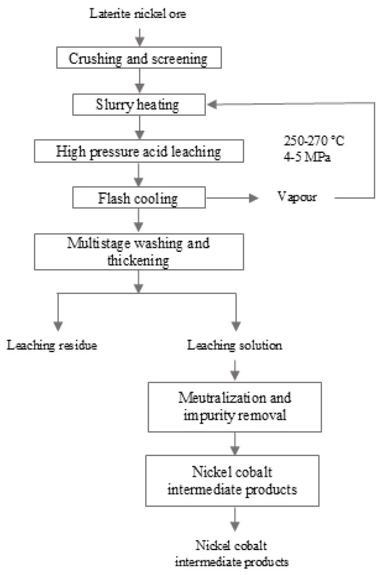
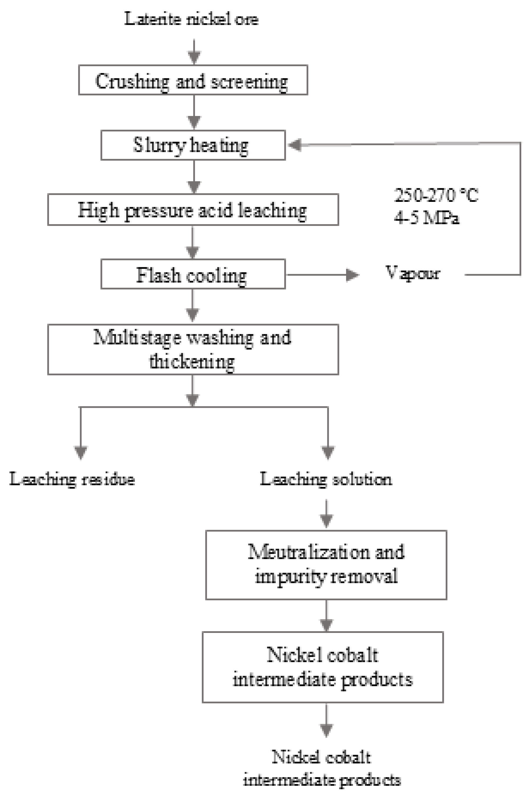
Nickel is an important strategic metal and has been widely used in stainless steel, alloy steel, electroplating, and new-energy batteries [1,2,3,4,5]. With the progressive depletion of global sulfide nickel ore resources, laterite nickel ores have gradually become the primary target for nickel resource development [2,6,7,8,9]. After being processed by the high-pressure acid leaching (HPAL) process (Figure 1), laterite nickel ores can produce a nickel–cobalt hydroxide precipitate (MHP) as an intermediate product, which has become an important source of raw materials for nickel–cobalt metallurgy [10,11,12,13,14,15,16]. The HPAL operation is carried out under elevated pressure (30–50 atm) and at temperatures ranging from 250 °C to 270 °C. A sulfuric acid solution is typically employed as the leaching agent to extract Ni, Co, Fe, Al, and other metallic species from lateritic ores [17,18]. Subsequently, by regulating the pH to 2.0–2.5, impurities including Fe, Al, and Si are hydrolyzed and precipitated, thus reporting to the solid residue, whereas Ni and Co are selectively maintained in the pregnant leach solution. This solution is then subjected to either sulfide precipitation or neutralization to produce a nickel–cobalt intermediate concentrate that is rich in both metals. The final product can be either directly commercialized or sent to conventional refining routes for the production of electrolytic nickel or nickel sulfate. However, in addition to valuable metals such as nickel and cobalt, MHP also contains various impurity elements including manganese, zinc, iron, magnesium, and calcium [19]. How to efficiently remove these impurities and obtain qualified nickel products remains a key technical challenge in the resource utilization of MHP.
Figure 1.
Flowchart of HPAL for laterite nickel ore.
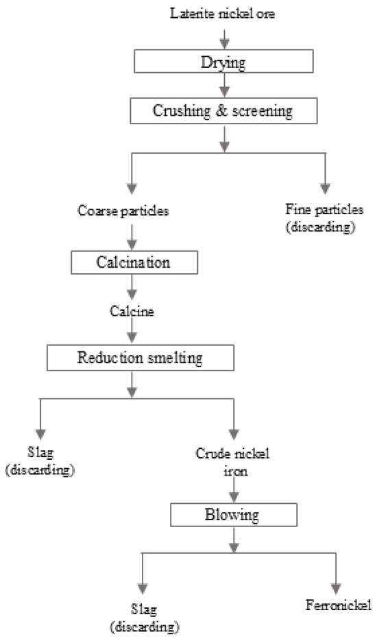
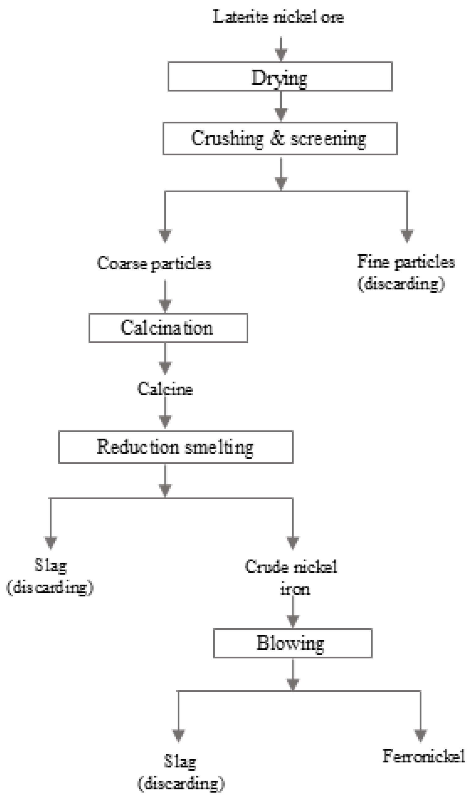
There are two primary technical routes for recovering nickel and cobalt from MHP: alkaline leaching and acid leaching. In the alkaline system, an ammonium carbonate–ammonia solution is commonly employed as the lixiviant. Through the formation of stable metal–amine complexes, this approach enables the preferential dissolution of nickel and cobalt over manganese [20]. Nevertheless, despite its certain selectivity, this process faces considerable challenges in the subsequent separation of nickel from cobalt, often necessitating the introduction of solvent extraction to achieve effective partitioning. Furthermore, cobalt is susceptible to oxidation under alkaline conditions, which not only consumes substantial amounts of expensive organic reagents but also complicates the overall process flow. In addition, this route demands thorough extraction and deep purification of nickel. Owing to these inherent drawbacks, acid leaching has gained increasing attention in the academic community and has become one of the mainstream choices for MHP processing. In recent years, research on selective acid leaching systems for MHP has grown rapidly, with the core strategy being the addition of oxidants in a sulfuric acid medium to achieve stepwise and effective dissolution of nickel, cobalt, and manganese. However, the nickel extraction efficiency in such processes has been found to reach only about 90%, representing a clear limitation [21,22,23]. In recent years, combined pyro-hydro metallurgical processes have attracted extensive attention due to their advantages of short flow sheets and high impurity removal efficiencies. Traditional pyrometallurgical processes can be broadly classified into two categories: the ferronickel route and the nickel matte route [24]. The ferronickel route primarily includes the rotary kiln–electric furnace (RKEF) smelting process (Figure 2) and blast furnace smelting process, among others [25,26,27]. The nickel matte route encompasses blast furnace matte smelting, rotary kiln matte smelting, converting of ferronickel to matte in converters, and oxygen-enriched side-blown bath smelting. Among these, the route involving drying, pre-reduction, and subsequent electric furnace reduction smelting of MHP to produce crude nickel anodes, followed by electrorefining to obtain electrolytic nickel, offers a new approach for the efficient utilization of MHP [28]. However, the migration behavior of impurity elements during this smelting process remains unclear, which will adversely affect the purity control of the subsequent nickel products.
Figure 2.
Process of RKEF.
In this study, pre-reduced calcine derived from laterite nickel MHP was used as feed material, and semi-industrial reduction smelting tests were carried out in a 40 kVA single-phase electric arc furnace. The migration behaviors of sulfur, manganese, and zinc are systematically investigated as they are recognized as typical impurities that adversely affect the crude nickel quality and subsequent electrorefining performance. Cobalt, although present in the feed and co-enriched in the alloy phase (as confirmed by EDS), is a valuable product component rather than an impurity and will be addressed in a separate study focusing on Ni–Co co-recovery. Iron and aluminum, owing to their strong slag-forming tendency (as FeO and Al2O3) and negligible partitioning into the metallic phase under the applied smelting conditions, are not considered as critical impurities in this work. The phase compositions of crude nickel and slag were characterized by X-ray diffraction (XRD), scanning electron microscopy (SEM), and energy-dispersive spectroscopy (EDS), aiming to reveal the directional separation mechanism of impurity elements. This work is expected to provide a theoretical basis and data support for optimizing the process parameters of MHP electric furnace smelting, controlling the quality of crude nickel, and ensuring the stable operation of the subsequent electrorefining step.
2. Materials and Methods
2.1. Materials
The raw material used in this study is a nickel–cobalt hydroxide enrichment imported from the Republic of Turkey, and its chemical composition is listed in Table 1. This nickel–cobalt enrichment is a light-green paste that is insoluble in water, with a fine particle size, and 100% of the material passes through a 300-mesh sieve.
Table 1.
Chemical composition of raw materials.
Anthracite, coke, silicon dioxide and quartz powder were of industrial grade and purchased from Xilong Chemical Co., Ltd. (Shantou, China) and Sinopharm Chemical Reagent Co., Ltd. (Shanghai, China). The anthracite and coke powder used in this study were crushed and screened to −100 mesh, and the coke blocks for arc initiation were approximately 20–30 mm in size. For chemical analysis, all solid samples (crude nickel, slag, feed, and pre-reduced calcine) were digested using a mixed acid system consisting of hydrochloric acid, nitric acid, and hydrofluoric acid (all of analytical grade, purchased from Sinopharm Chemical Reagent Co., Ltd.) (Shanghai, China). Deionized water (resistivity ≥ 18.2 MΩ·cm) was used throughout for solution preparation. All reagents were used without further purification.
2.2. Preparation of Pre-Reduced Pellets
The nickel–cobalt hydroxide concentrate (a light-green paste, 100% passing through a 300-mesh sieve) was mixed with quartz powder (SiO2 purity ≥ 98%, d50 = 75 μm) and pulverized coal (fixed carbon ≥ 75%, volatile matter 8–10%, ash ≤ 12%) in a mass ratio of 100:10:10. Water (10 wt% relative to the mixture) was added and thoroughly blended, and the mixture was then pelletized using a disk pelletizer to obtain pellets with diameters of 8–12 mm. The green pellets were dried at 105 °C for 4 h. Subsequently, the dried pellets were placed in corundum crucibles, covered with lids, and pre-reduced in a muffle furnace. The temperature was raised to 900 °C at a heating rate of 10 °C/min and held at 900 °C for 3 h. After reduction, the crucibles were removed from the furnace and allowed to cool naturally to room temperature in air. The pre-reduced product was then crushed, riffled, and ground to −200 mesh for sample preparation and chemical analysis. The composition of the obtained pre-reduced calcine is shown in Table 2, and the calcine was used as the feed material for electric arc furnace smelting.
Table 2.
Composition of dried pre-reduced product.
2.3. Methods
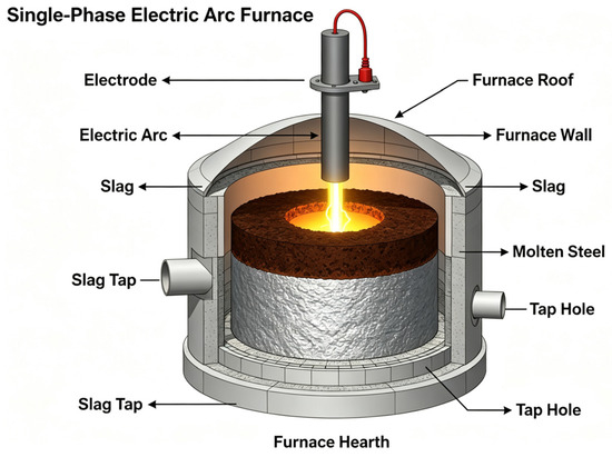
The experiment was carried out in a 40 kVA single-phase electric arc furnace manufactured by Xi’an Electric Furnace Factory (Xi’an, China). The 40 kVA electric arc furnace used in this study had a nominal capacity of 10 kg per heat under standard operating conditions. The inner dimensions of the furnace chamber were 330 mm × 200 mm × 230 mm. The furnace was lined with magnesia-chrome bricks and densely packed with magnesia ramming material around the lining; the furnace cover was made of refractory concrete, and the electrode diameter was 65 mm. A schematic diagram of the experimental setup is shown in Figure 3.
Figure 3.
Schematic diagram of the single-phase arc furnace.
The furnace charge consisted of pre-reduced pellets, which were prepared by blending the dried nickel–cobalt hydroxide enrichment with 10 wt% anthracite (fixed carbon ≥ 75%, volatile matter 8–10%, ash ≤ 12%) and 10 wt% quartz powder (SiO2 ≥ 98%, d50 = 75 μm) as flux, followed by pelletizing, drying, and pre-reduction roasting at 900 °C for 3 h. The flux rate, defined as the mass ratio of added SiO2 to the dry enrichment, was fixed at 10% for all heats, targeting a slag CaO/SiO2 ratio of approximately 0.3–0.4 to ensure adequate fluidity of the silicate slag at the smelting temperature. The pre-reduced pellets used for all seven heats contained approximately 29.91% Ni, 3.88% S, 0.60% Zn, and 0.015% residual carbon (the balance being mainly O, Mg, Si, Mn, and other minor components). During smelting, the furnace cover was kept closed without any inert gas purging; the reducing atmosphere was maintained by the combustion of carbonaceous materials and the evolution of CO from reduction reactions and was qualitatively assessed by visual observation of the flame color and the absence of visible dust entrainment in the off-gas. Quantitative off-gas analysis (e.g., O2, CO, CO2) was not performed due to equipment limitations at the semi-industrial scale.
Before each test, the residual incandescent coke in the furnace was cleared out, and then a predetermined amount of furnace charge was fed into the chamber. Arc initiation was carried out by the carbonaceous material method, i.e., by placing coke or waste graphite electrode blocks onto the charge surface between the two electrodes. During the arc initiation stage, the secondary voltage was controlled at 70–80 V and the secondary current at 320–350 A; during the heating and melting stage, the secondary voltage was adjusted to 80–90 V, and the secondary current was increased to 380–400 A. The target smelting temperature was set at 1550 °C for all heats. However, in an electric arc furnace, the arc zone temperature is significantly higher, while the bulk melt temperature is lower and governed by the power input and heat balance. Due to the strong stirring effect of the arc and the insulation provided by the slag layer, the molten bath can be regarded as thermally relatively uniform during tapping. The actual melt temperature at tapping was measured using a portable infrared pyrometer positioned approximately 0.5 m above the molten stream. The measured tapping temperatures varied from 1480 °C to 1560 °C among the heats, depending on the heat input and the amount of residual metal retained from previous runs. Complete melting of the charge was confirmed by probing the melt with a steel bar to ensure that no solid residues remained at the furnace bottom; the time required from arc initiation to complete melting was approximately 20–35 min. Timing began after the charge was completely melted, and this duration is designated as the holding time in Table 1. In the first two heats only, additional coke powder was supplemented as a reductant; for Runs 3–7, no external reductant was added, and the reduction relied solely on the residual carbon in the pre-reduced pellets. The total carbon input for each heat is listed in Table 1. During the smelting process, the melt condition was regularly probed with a steel bar, and slag samples were periodically taken with a pre-heated steel ladle from the melt surface near the electrode tip at intervals of approximately 15, 30, and 45 min after complete melting (or until tapping for shorter heats). After smelting, the slag and crude nickel melt were poured together into an iron ladle, and after cooling, they were weighed, sampled, and prepared for chemical analysis. All collected solid samples (crude nickel drillings, slag chunks, and feed materials) were stored in sealed polyethylene bags under ambient conditions prior to sample preparation and chemical analysis.
2.4. Chemical Analysis Methods
Ni, Co, Fe, Mn, Zn, Si, Al, Ca, and Mg were determined by inductively coupled plasma optical emission spectrometry (ICP-OES, Thermo Scientific iCAP 7400, Thermo Fisher Scientific, Waltham, MA, USA). Sulfur and residual carbon were measured by high-frequency combustion-infrared absorption method using a LECO Corporation, St. Joseph, MI, USA. All chemical analyses were performed in duplicate, and the relative deviation between the two test results was controlled within 5%.
2.5. X-Ray Diffraction (XRD) Analysis
Powder X-ray diffraction (XRD) patterns of crude nickel–cobalt scrap and slag samples were collected on a Rigaku SmartLab 9 kW diffractometer (Rigaku Corporation, Tokyo, Japan) with Cu Kα radiation (λ = 1.5406 Å). The operating voltage was 40 kV, and the current was 150 mA. Continuous scanning was performed over the 2θ range of 10–90° with a step size of 0.02° and a scan rate of 4°/min. Phase identification was carried out using MDI Jade 6.5 software combined with the ICDD PDF-4+ database.
2.6. SEM-EDS and Optical Microscopy Observation
The crude nickel samples were obtained by drilling at selected points on the surface of the massive crude nickel. Although this sampling method cannot cover the central region of the ingot, the rapid cooling of the small-sized ingots in cast-iron molds effectively suppresses macrosegregation, ensuring overall compositional consistency between the surface layer and the interior. The samples were ground step-by-step with SiC abrasive papers down to 1200 grit, followed by polishing with 1 μm diamond paste. A thin carbon film was coated on polished surfaces for electrical conduction. Microstructural observation was performed on a Zeiss Axio Imager M2m optical microscope (Carl Zeiss AG, Oberkochen, Germany). Back-scattered electron (BSE) imaging and energy-dispersive X-ray spectroscopy (EDS) were carried out on a Zeiss Sigma 300 field-emission scanning electron microscope (FE-SEM) (Carl Zeiss AG, Oberkochen, Germany) equipped with an Oxford X-Max 80 mm2 SDD detector (Oxford Instruments, Abingdon, Oxfordshire, UK). Operating conditions: Acceleration voltage 20 kV, working distance 8–10 mm, probe current 1.0 nA. The acquisition time for each EDS point spectrum was no less than 60 s, and semi-quantitative analysis was performed using the ZAF correction method.
2.7. Main Chemical Reactions Considered During Smelting
The electric furnace smelting of pre-reduced MHP involves multiple simultaneous reactions. Based on the feed composition (C, NiO, MnO, ZnO, Fe2O3, SiO2, CaO, MgO, and sulfur-bearing phases) and the operating temperature (1550 °C), the following reactions were considered as the most thermodynamically relevant for interpreting the migration behaviors of Ni, S, Mn, and Zn.
The residual carbon in the pre-reduced pellets serves as the primary reductant. The key metal oxide reduction reactions are:
- NiO + C → Ni + CO (R1)
- NiO + CO → Ni + CO2 (R2)
- MnO + C → Mn + CO (R3)
- Fe2O3 + 3C → 2Fe + 3CO (R4)
- ZnO + C → Zn(g) + CO (R5)
Among these, R1 and R2 are the principal routes for nickel recovery. The reduction of MnO (R3) is thermodynamically less favorable than that of NiO at 1550 °C, which explains the preferential retention of Mn in the slag phase.
Sulfur in the feed is mainly present as sulfates or organic sulfur. At high temperature and under reducing conditions, it is converted to H2S or S2, which then reacts with metallic nickel:
- 2SO2 + 4C → S2 + 4CO (R6)
- 3Ni + S2 → Ni3S2 (R7)
- 3Ni + 2H2S → Ni3S2 + 2H2 (R8)
The gangue components (SiO2, CaO, MgO, MnO, FeO) react to form a liquid silicate slag. The main slag-forming reactions are:
- 2FeO + SiO2 → 2FeO·SiO2 (fayalite) (R9)
- 2MnO + SiO2 → Mn2SiO4 (manganese olivine) (R10)
- 2MgO + SiO2 → Mg2SiO4 (forsterite) (R11)
- CaO + SiO2 → CaO·SiO2 (wollastonite) (R12)
Zinc is removed from the system through a coupled reduction–volatilization path. Metallic zinc, once formed by R5, has a boiling point of 907 °C and immediately vaporizes under the smelting temperature of 1550 °C:
- Zn(l) → Zn(g) (R13)
2.8. Data Calculation and Analysis
The nickel recovery refers to the proportion of nickel entering the target product (crude nickel or slag). Two methods are used: the recovery calculated based on crude nickel (direct calculation) and the recovery calculated based on slag (derived from the nickel loss in slag). Each smelting condition was repeated three times, and the average values with standard deviations are reported. Owing to the limitations of the semi-industrial scale, some replicate experiments were unsuccessful; to compensate for this, we performed multiple sampling verifications and cumulative mass balance cross-checks to ensure the reliability of the data.
Nickel recovery based on crude nickel (RNi,Crude nickel)
Nickel recovery based on slag (RNi,Slag)
where CNi,Crude nickel and CNi,Slag are the nickel grade in crude nickel (mass fraction, %) and nickel content in furnace slag (mass fraction, %), respectively. CNi,Furnace charge is the nickel grade in furnace feed (pre-reduced pellets) (mass fraction, %).
The distribution fractions of a specific element M (e.g., S, Mn, Zn) into crude nickel and slag were determined by mass balance according to Equations (3) and (4):
where mCrude, mSlag, and mFurnace charge are the masses of crude nickel, slag, and furnace charge (pre-reduced pellets), respectively; Ci,crude and Ci,slag are the concentrations of element M in crude nickel and slag (mass fraction, %), respectively; Ci,charge is the concentration of element M in the furnace charge. The fraction of element M reporting to flue gas, dust, and furnace retention (designated as “Other” in Tables) was obtained by the difference:
3. Results and Discussion
3.1. Migration Behavior of Nickel During Electric Furnace Smelting
As shown in Table 3, a total of seven smelting runs (including those for preparing crude nickel product) were carried out in this semi-industrial test, processing 102.6 kg of pre-reduced product of nickel–cobalt hydroxide enrichment in total and yielding 31.79 kg of crude nickel and 42.11 kg of slag. Among them, the first five runs were condition tests, mainly investigating the effects of reductant dosage (run 1, run 2 and run 5), smelting time (run 3, run 4, run 5), and feed amount (run 3 and run 6) on smelting performance; the last two runs focused on the preparation of crude nickel product, with relatively higher feed amounts and shorter smelting times.
Table 3.
Melting test data of 40 kVA electric furnace.
During smelting, the final distribution of the various elements mainly includes the following: entering the crude nickel product, entering the slag, and escaping as gases (CO, CO2, SO2, and Zn vapor) and dust, with a minor fraction remaining in the furnace and as operational losses. Under suitable reduction smelting conditions, the manganese content in crude nickel could be controlled below 0.2%, while the slag contained about 9% manganese, and over 80% of the manganese in the charge entered the slag phase. The zinc contents in both crude nickel and slag were below 0.1%, and over 90% of the zinc in the charge volatilized into the flue gas. The low levels of manganese and zinc are beneficial for the subsequent electrorefining process of crude nickel.
The data concerning nickel recovery in the experiments are summarized in Table 4.
Table 4.
Nickel recovery test data.
Run 1 was charged with 15 kg of pellets and 4% external coke (600 g), smelted for 60 min at a tapping temperature of 1480 °C. The slag weight was 3.43 kg, and the crude nickel weight was 2.9 kg. The crude nickel grade was 67.61% Ni, and the slag contained 0.019% Ni. The slag-based nickel recovery was 99.82%, while the crude nickel-based recovery was 88.64%. The extremely low nickel content in the slag was due to excessive reduction, but the low crude nickel recovery indicated that part of the metal had penetrated into the lining or remained inside the furnace. Run 2 was charged with 10 kg of pellets and 3% external coke (300 g), smelted for 105 min at 1520 °C. The slag weight was 6.36 kg, and the crude nickel weight was 6.29 kg. The crude nickel grade was 74.95% Ni, and the slag contained 0.021% Ni. The slag-based recovery was 98.56%, and the crude nickel-based recovery was 86.19%. Similarly, the very low slag nickel content resulted from excessive reduction, while the low crude nickel recovery was due to metal retention. Overall, the first two runs suffered from over-reduction, as evidenced by the relatively low nickel grades and higher manganese and iron contents in the crude nickel. From the third run onward, no external coke was added, and reduction relied solely on the residual carbon (~0.015%) in the pellets. In Run 3, 10 kg of charge was smelted at 1550 °C for 50 min, with no external coke addition. After complete melting, samples were taken at intervals: the nickel content in slag was 2.27% at 15 min, 2.00% at 30 min, and 1.01% at 45 min, and it dropped to 0.24% at tapping (50 min), confirming that nickel had been largely enriched in the crude nickel phase during melting. The slag weight was 3.67 kg, and the crude nickel weight was 3.24 kg. The crude nickel grade was 84.01% Ni, with Mn 0.13%, S 7.22%, and Zn 0.036%. The slag-based nickel recovery was 99.71%, and the crude nickel-based recovery was 91.00%. A small amount of product remained in the furnace. This run demonstrated that proper control of reduction intensity and charge amount could yield excellent crude nickel quality and low nickel content in slag.
In Run 4, the charge was increased to 15 kg, with no external coke, smelted at 1500 °C for 90 min. The slag weight was 6.50 kg, and the crude nickel weight was 4.70 kg. The crude nickel grade was 82.19% Ni, and the slag contained 1.77% Ni. The slag-based recovery was 97.83%, and the crude nickel-based recovery was 86.10%, again showing the issue of crude nickel retention. In Run 5, 15 kg of charge was smelted at 1560 °C for 60 min, with no external coke. The slag weight was 9.35 kg, and the crude nickel weight was 6.28 kg. The crude nickel grade was 79.36% Ni, and the slag contained 1.85% Ni. In Run 5, the slag-based nickel recovery was 96.20%, indicating efficient slag–metal separation. However, due to the accumulation of a molten metal pool in the furnace, the single-run crude nickel-based recovery is subject to significant carryover errors. When Runs 4 and 5 are combined for a cumulative mass balance, the overall nickel recovery into crude nickel and slag reaches approximately 98.6%, which is in good agreement with the slag loss-derived efficiency.
Run 6 and Run 7 are focused on producing crude nickel product. Run 6 used 18.5 kg of charge, with no external coke, smelted at 1540 °C for 45 min. The slag weight was 6.30 kg, and the crude nickel weight was 4.96 kg. The crude nickel grade was 82.30% Ni, and the slag contained 4.80% Ni. The slag-based recovery was 96.48%, but the crude nickel-based recovery was only 89.86%, indicating that most of the charge remained unmelted. Run 7 used 18.8 kg of charge, with no external coke, smelted at 1530 °C for 30 min. The slag weight was 8.50 kg, and the crude nickel weight was 6.99 kg. The crude nickel grade was 83.60% Ni, and the slag contained 2.68% Ni. The slag-based recovery was 96.95%, and the crude nickel-based recovery was 89.06%. The short smelting time again caused incomplete melting and low metal recovery.
The tests indicate that in production, a single addition of coal can be adopted, i.e., the reductant is fully blended during pelletizing without further addition during reductive smelting. This simplifies operation and eliminates the need for an additional feeding system. Based on the results of Runs 3–5 (with no external coke addition and moderate charge amounts), it is evident that the pre-reduced product of nickel–cobalt enrichment is amenable to crude nickel smelting. By properly controlling the reduction depth and smelting time, good technical indicators can be achieved, such as a crude nickel grade of about 80%, a slag nickel content that can be reduced to a low level (e.g., 0.24% in Run 3), and a nickel recovery of 91–95% in the crude metal.
3.2. Migration Behavior of Sulfur During Electric Furnace Smelting
As the charge contained 3.88% sulfur, the sulfur content in the crude nickel obtained from the seven smelting runs fluctuated in the range of 6.41–10.36%. Among them, the sulfur content in crude nickel from the fourth run was 10.36%, and that from the fifth run was 8.50%. The sulfur content in the slag was generally low, with the lowest value being 0.044% (Run 5) and the highest being 0.17% (Run 7), all below 0.2%. The distribution data of sulfur during smelting are shown in Table 5.
Table 5.
Sulfur trend during smelting.
In the scaled-up tests, the sulfur was mainly distributed between the crude nickel and the “Other” fraction (flue gas, dust, and furnace retention), with only 1.26–1.38% of the sulfur in the charge entering the slag phase. Specifically, the sulfur distribution into crude nickel ranged from 44.36% (Run 1) to 83.66% (Run 4), while the “Other” fraction ranged from 15.02% (Run 4) to 54.36% (Run 1). Further analysis of the data from individual runs shows that the sulfur content in crude nickel tended to increase with a decrease in the degree of reduction or an increase in the nickel content of the slag. For example, in the first run, the nickel content in the slag was only 0.019%, corresponding to a sulfur content in crude nickel of 6.41% and a sulfur distribution into crude nickel of 44.36%; in the second run, the slag nickel content was 0.021%, and the crude nickel sulfur content was 7.46%; when the nickel content in the slag increased to 0.24% in the third run, the sulfur content in crude nickel rose to 7.22%, whereas in the fourth and fifth runs, the nickel contents in the slag reached 1.77% and 1.85%, respectively, and the sulfur contents in crude nickel increased significantly to 10.36% and 8.50%.
Overall, during the electric furnace smelting of the pre-reduced charge, the sulfur in the charge was predominantly partitioned into the crude nickel phase (44.36–83.66% of the total sulfur), with only a minor portion (1.26–1.38%) entering the slag. The remainder reported to the “Other” fraction, which includes flue gas, dust, and furnace retention. The observed variations in sulfur content may be related to the sampling method for crude nickel: due to the high hardness of the crude nickel ingots, even with high-strength drill bits, only the surface layer samples could be collected, and the surface layer tends to have a higher sulfur content, thereby causing deviations in the analytical results.
The distribution of sulfur between crude nickel and slag is governed by the thermodynamic equilibrium between the Ni–S melt and the silicate slag phase. At 1550 °C, sulfur has a relatively high solubility in liquid nickel, and the dissolution reaction ½S2(g) = [S]_Ni has a negative standard Gibbs free energy, indicating that this process is thermodynamically favorable. Under strongly reducing conditions (Runs 1 and 2), the oxygen potential of the melt decreased, and the concurrent decrease in FeO content in the slag led to a lower sulfide capacity; these factors caused sulfur to be predominantly distributed into the crude nickel and the “Other” fraction, rather than the slag. Under insufficient reduction (Runs 4 and 5), the elevated NiO content in the slag increased the oxygen potential, allowing a portion of sulfur to enter the slag phase. However, because the affinity of sulfur for nickel is much stronger than its bonding with the silicate network, sulfur still remained mainly in the crude nickel, with only a minor fraction entering the slag.
3.3. Migration Behavior of Manganese During Electric Furnace Smelting
The data concerning the distribution of manganese in the semi-industrial tests are shown in Table 6.
Table 6.
Manganese trend during smelting.
As can be seen from the data, in the first and second runs, due to excessive reduction, part of the manganese minerals in the charge was reduced and entered the crude nickel, resulting in manganese contents in crude nickel as high as 7.53% and 5.43%, respectively, while the manganese contents in the slag were 6.51% and 7.34%, respectively. In the third run, the reduction degree was properly controlled; although the nickel content in the slag was only 0.24%, the manganese content in crude nickel was as low as 0.13%. For this run, a slag sample taken at 15 min after complete melting showed a manganese content of 9.97%; after 50 min of reduction, the tapped slag had a manganese content of 9.86%. The two values are essentially consistent, indicating that under smelting conditions that ensure a relatively high nickel recovery, most of the manganese minerals in the charge remain unreduced, and crude nickel with a manganese content below 0.2% can be stably obtained. In the last four runs (Runs 4–7), due to insufficient reduction depth (as reflected by the relatively high nickel content in the slag), the manganese content in crude nickel was only in the range of 0.10–0.15%, while the manganese content in the slag fluctuated between 9.75% and 9.94%. Based on the results of the third run, it is estimated that the amount of manganese entering the crude nickel phase accounted for less than 1% (specifically 0.74%) of the total manganese in the charge, indicating that the manganese removal efficiency of this process is highly satisfactory.
The distribution of manganese depends on the relative reduction thermodynamics of NiO and MnO. At 1550 °C, the standard Gibbs free energy of formation of NiO is less negative than that of MnO, indicating that nickel is preferentially reduced by carbon, while MnO is thermodynamically more stable and remains mainly as oxide in the slag phase—this is the fundamental reason for manganese enrichment in the slag. Under strongly reducing conditions (Runs 1 and 2), the elevated carbon potential caused over-reduction of MnO to metallic manganese, which dissolved into the crude nickel, resulting in manganese contents as high as 7.53% and 5.43% in the crude nickel. Under moderate reduction (Run 3), nickel was sufficiently reduced while manganese was essentially not reduced, allowing the manganese content in crude nickel to be reduced to below 0.13%, with a manganese removal efficiency exceeding 99%. Manganese has a relatively high activity in liquid nickel, and its high affinity for oxygen causes it to preferentially form MnO in oxygen-bearing melts, further enhancing the tendency of manganese to enrich in the slag phase.
3.4. Migration Behavior of Zinc During Electric Furnace Smelting
The data concerning the distribution of zinc in the semi-industrial tests are shown in Table 7.
Table 7.
Trend of zinc in smelting process.
The data show that the zinc content in crude nickel obtained from the seven smelting runs ranged from 0.022% to 0.145%, while the zinc content in the slag ranged from 0.0025% to 0.22%. As the degree of reduction deepened, the zinc content in the slag tended to decrease, whereas that in crude nickel correspondingly increased. In the excessively reduced first and second runs, the crude nickel had the highest zinc contents, reaching 0.145% and 0.105%, respectively, while the slag had the lowest zinc contents of only 0.0025% and 0.0036%, respectively; at this point, only 0.16–0.27% of the zinc in the charge entered the slag phase, while 6.30–8.92% remained in the crude nickel. In the third run, with a moderate reduction, the zinc content in crude nickel decreased to 0.036%, and that in the slag increased to 0.036%, with 2.20% of the charge zinc entering the slag and 1.94% remaining in the crude nickel; the zinc volatilization rates in both cases exceeded 90%. In the insufficiently reduced fourth and fifth runs, the zinc contents in the slag reached 0.11% and 0.12%, respectively, while the zinc contents in crude nickel were 0.028% and 0.030%, respectively. As for the sixth and seventh runs, which had the largest charge amounts but the shortest smelting times, the slag contained the highest zinc contents (0.20% and 0.22%, respectively), while the zinc contents in crude nickel were 0.025% and 0.022%, respectively. It can be seen that under the conditions of moderate reduction depth and high nickel recovery, crude nickel with a zinc content below 0.1% can be obtained, while the zinc volatilization rate from the charge can reach over 90%.
The high zinc volatilization rate (>90%) originates from its unique physicochemical properties: its boiling point is only 907 °C, far below the smelting temperature of 1550 °C, and its saturated vapor pressure is extremely high. During smelting, ZnO is first reduced by carbon or CO to metallic zinc, which then vaporizes instantaneously due to its boiling point being much lower than the bath temperature, entering the flue gas as vapor—this “reduction–volatilization coupling” mechanism ensures that once zinc is reduced, it rapidly leaves the melt, making it difficult to enrich in either crude nickel or slag. The residual zinc content in crude nickel is jointly influenced by temperature, reduction depth, and smelting time: higher temperatures lead to more complete volatilization; under insufficient reduction, zinc remains in the slag as ZnO (with slag zinc contents of 0.11–0.12% in Runs 4 and 5, respectively); under excessive reduction, zinc, once reduced and not volatilized in time, can partially dissolve in crude nickel (with crude nickel zinc contents of 0.145% and 0.105% in Runs 1 and 2, respectively). Furthermore, the activity of Zn in Ni exhibits a negative deviation, and its solubility is limited; excess zinc tends to precipitate and further volatilize, which favors zinc removal.
3.5. Characterization of Smelting Products
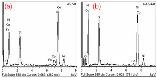
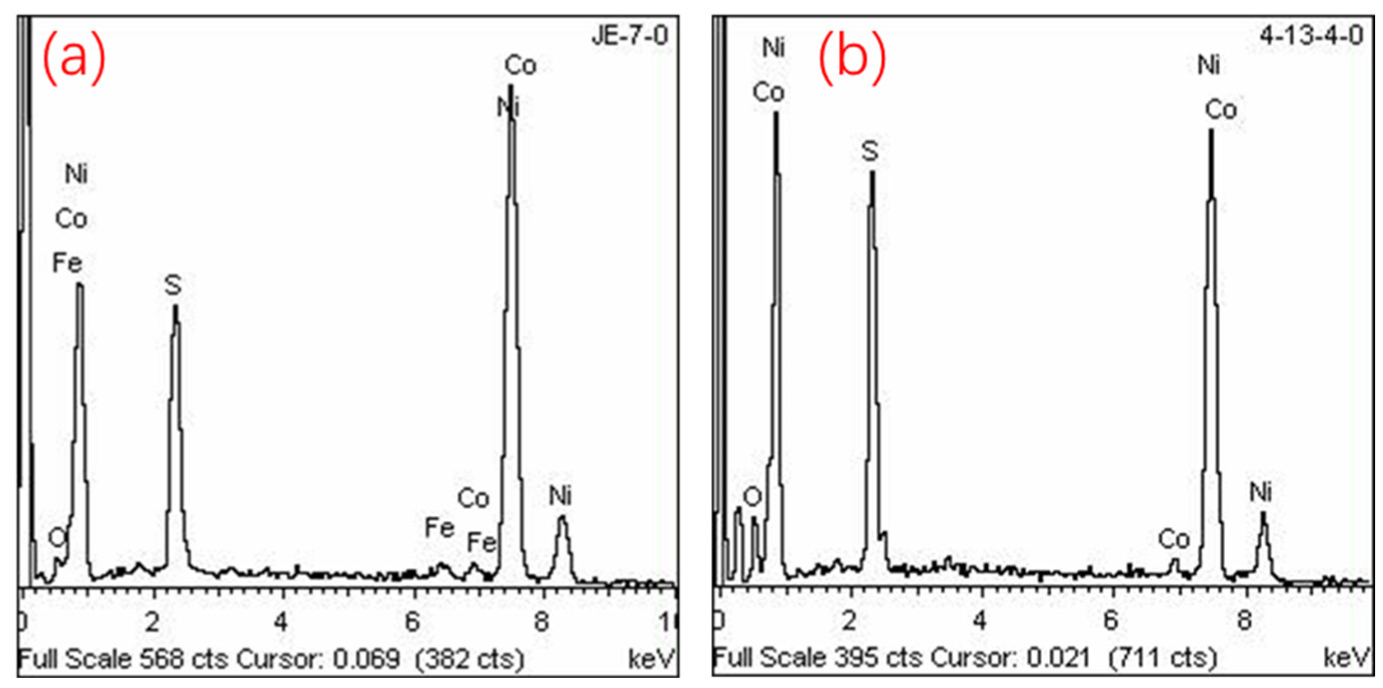
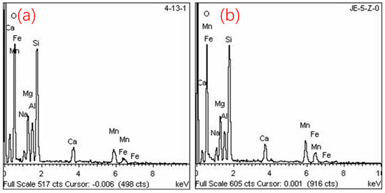
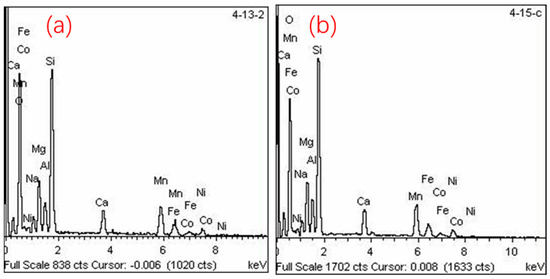
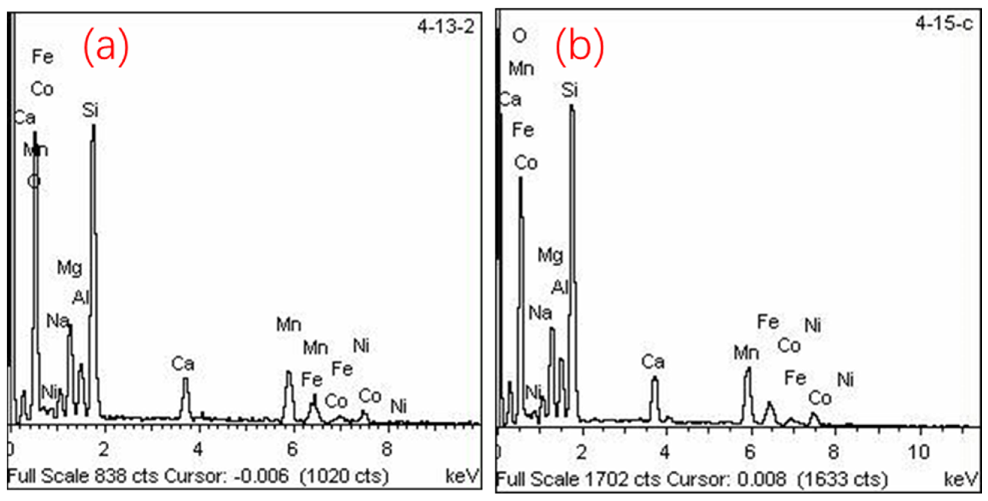
The phase compositions of representative crude nickel and slag samples were analyzed. The crude nickel samples were obtained by drilling at selected points on the surface of the massive crude nickel. The basic chemical composition of the drillings is shown in Figure 4, with Ni and S as the major components, along with small amounts of Co and Fe.
Figure 4.
(a) Energy spectrum of JE-7 coarse nickel cuttings; (b) energy spectrum of JE-6 coarse nickel cuttings.
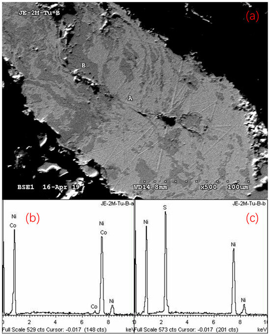
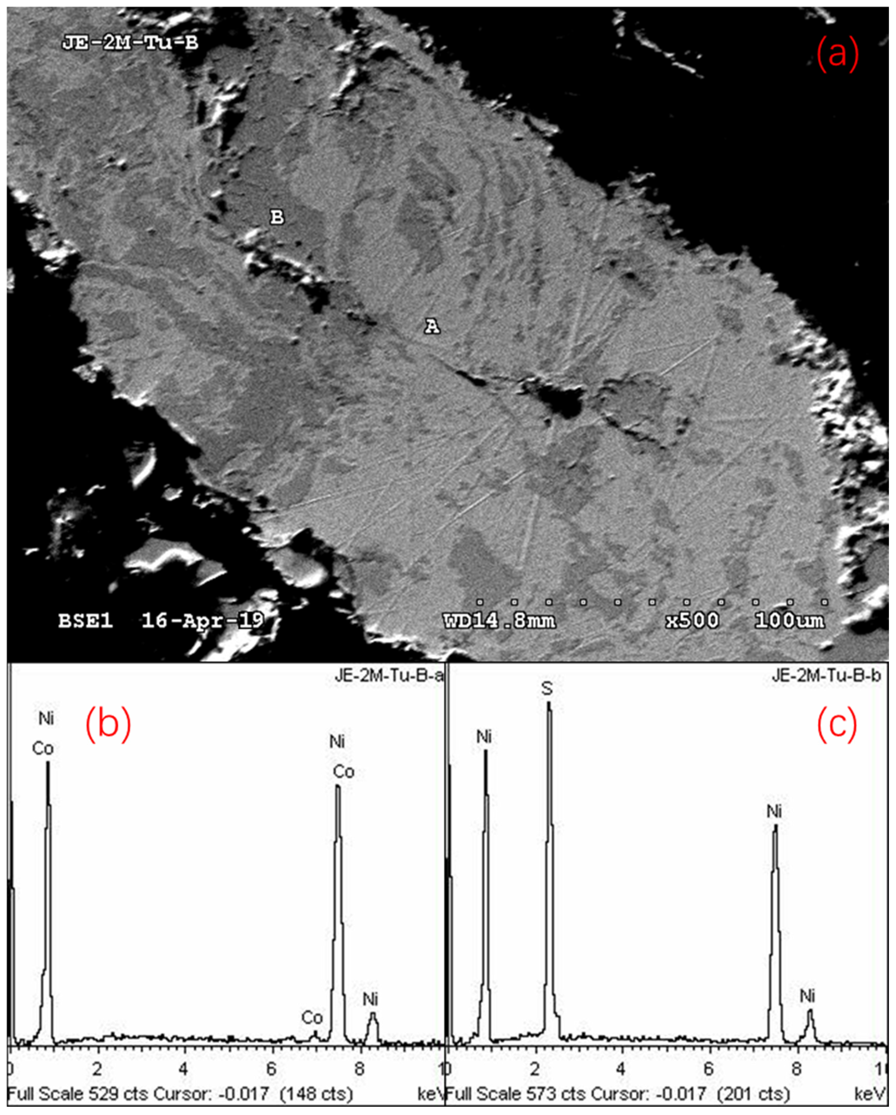
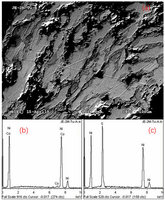
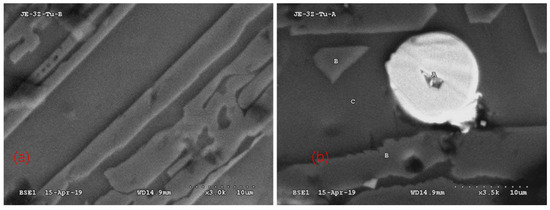
Microscopic observation and scanning electron microscopy (SEM) analysis of the polished sections of the drillings revealed that the microstructure of the crude nickel mainly consisted of two phases: a nickel-based alloy phase and a nickel matte phase (hexagonal nickel sulfide, Ni3S2) filling the interstices between the alloy particles. The two phases were closely distributed and exhibited an interwoven structure. The related SEM images and energy-dispersive spectroscopy (EDS) results are shown in Figure 4 and Figure 5, both of which display the same phase composition and associated features. The phase analysis data for the slag were not included in the present measurements.
Figure 5.
(a) Back-scattered electron image of JE-2 cuttings polished surface; (b) energy spectrum of analysis point A (bright white); (c) energy spectrum of analysis point B (white white).
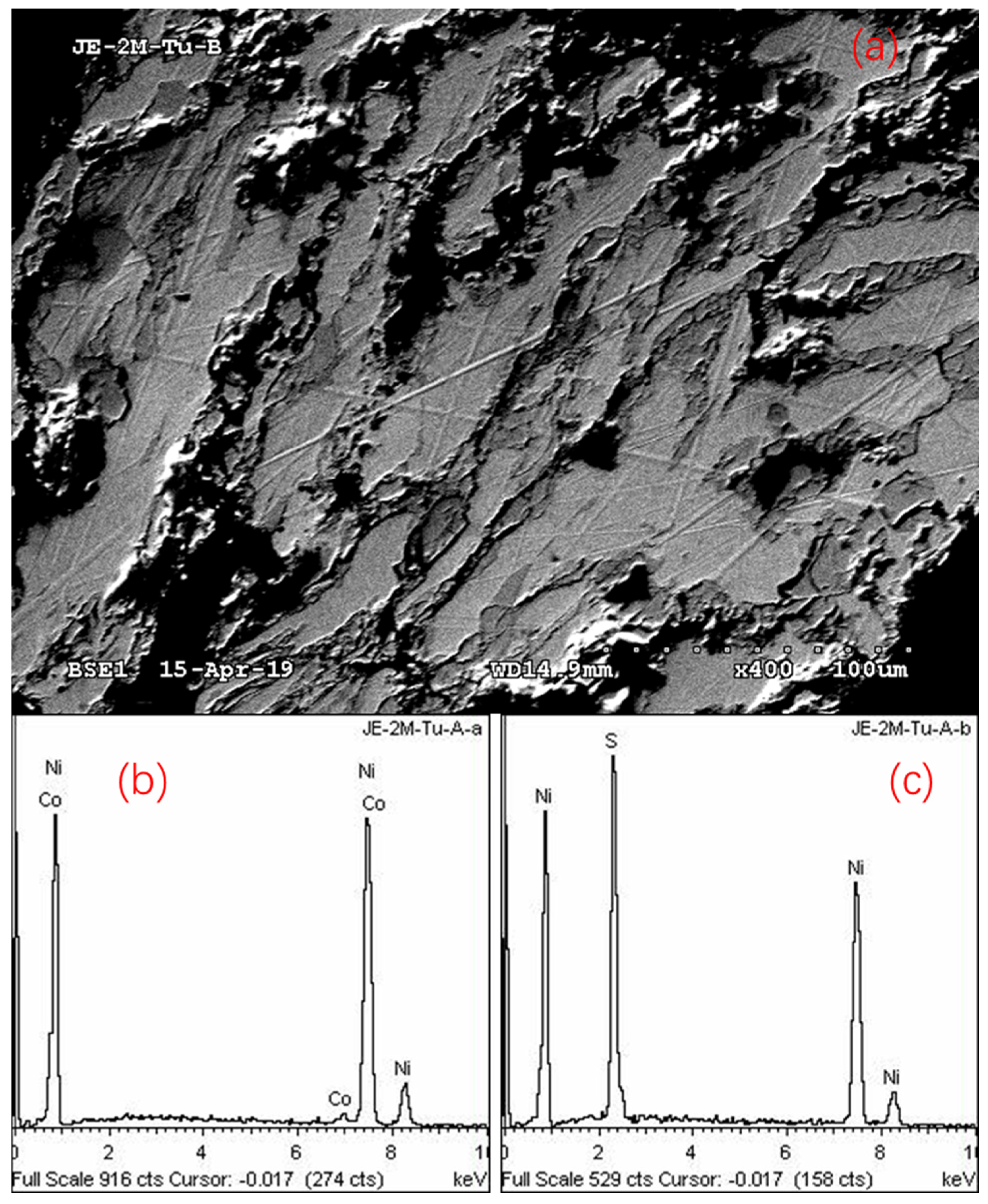
Combined with the results of SEM, EDS, and XRD, it can be further confirmed that the phases in the crude nickel mainly consist of two phases: a nickel-based alloy phase and a hexagonal nickel sulfide (Ni3S2) phase; in addition to a small amount of Co, the alloy phase actually also contains a small amount of Fe (not indicated in the EDS spectra). SEM/EDS analysis (Figure 6) also clearly shows that only the above two phases are present in the crude nickel drillings, which is consistent with the previous microscopic observations.
Figure 6.
(a) Back-scattered electron image of JE-6 cuttings polished surface; (b) energy spectrum of analysis point A (bright white); (c) energy spectrum of analysis point B (white white).
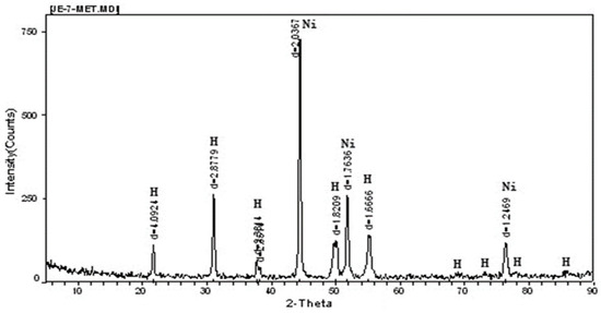
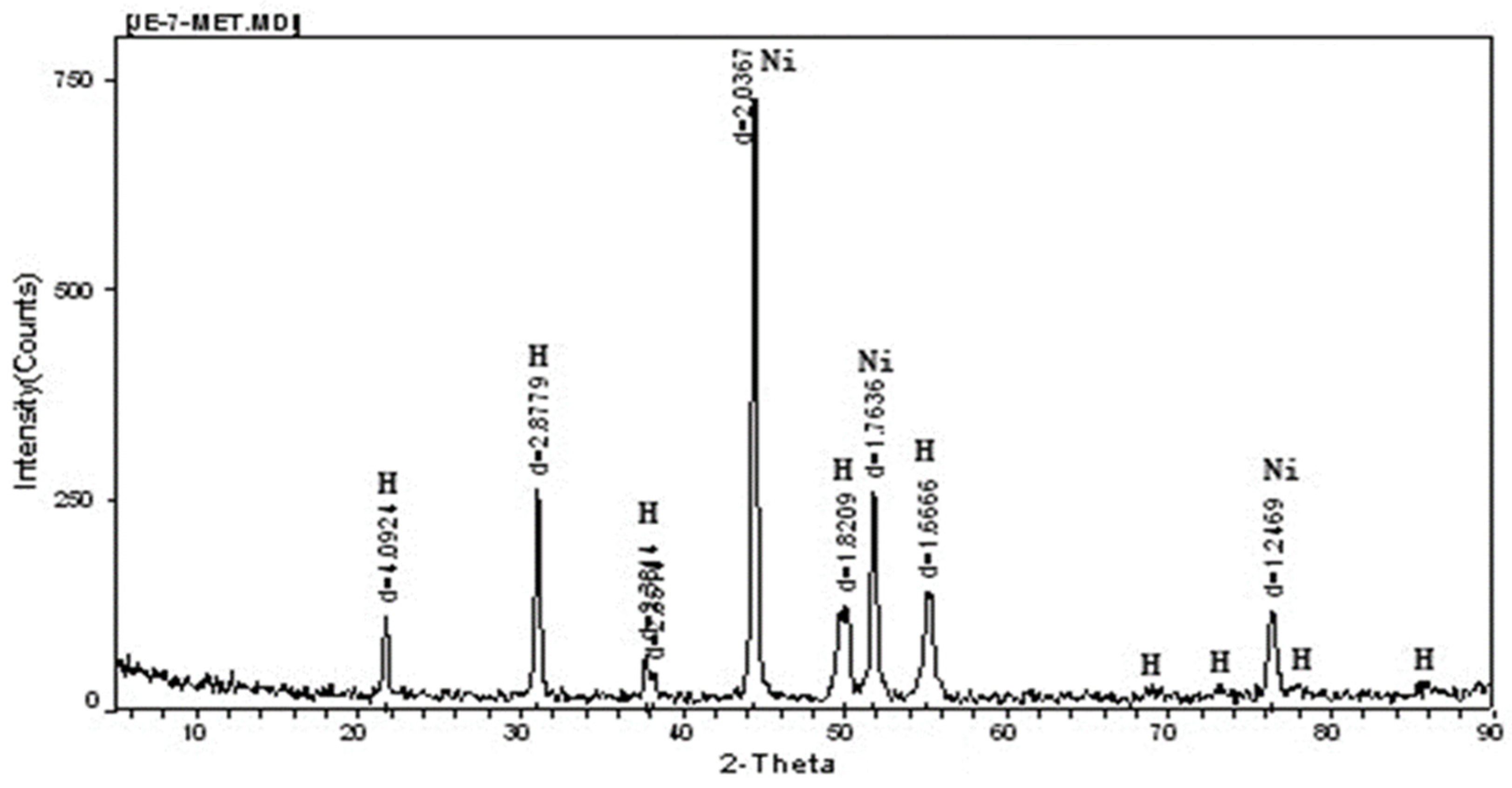
The calculation of the relative proportions of Ni3S2 and the Ni-based alloy phase from the total sulfur content of the crude nickel is based on the following assumptions and justifications. First, XRD analysis of the crude nickel drillings (Figure 7) reveals only two crystalline phases: metallic Ni and hexagonal Ni3S2; no other sulfur-bearing phases (e.g., NiS, MnS, or FeS) are detected within the detection limit of XRD. Second, SEM-EDS examination of polished sections (Figure 5 and Figure 6) consistently shows a two-phase microstructure consisting of a Ni-based alloy matrix and an intergranular sulfide phase, with EDS point analyses identifying the sulfide phase as Ni3S2. Third, according to the Ni–S binary phase diagram, Ni3S2 is the thermodynamically stable nickel sulfide phase upon solidification from the Ni–S melt, while other nickel sulfides (e.g., NiS) are not stable under the cooling conditions of the crude nickel ingot. Therefore, it is reasonable to assume that essentially all sulfur in the crude nickel is combined as Ni3S2. However, it should be noted that a minor fraction of sulfur may be present as solid solution in the Ni-based alloy or as trace sulfides below the XRD detection limit, which would introduce a small systematic error in the calculated phase proportions. The XRD pattern of the crude nickel drillings (Figure 7) indicates that the phases consist of metallic nickel (PDF#04-0850) and hexagonal nickel sulfide (heazlewoodite, Ni3S2, PDF#73-1395). The relative contents of the two phases mainly depend on the sulfur content of the feed material. Therefore, based on the sulfur content obtained from the chemical analysis of crude nickel, the relative proportions of the hexagonal nickel sulfide and the alloy phase can be calculated.
Figure 7.
Diffraction pattern of JE-7 coarse nickel cuttings (Ni-metallic nickel, H-Ni3S2).
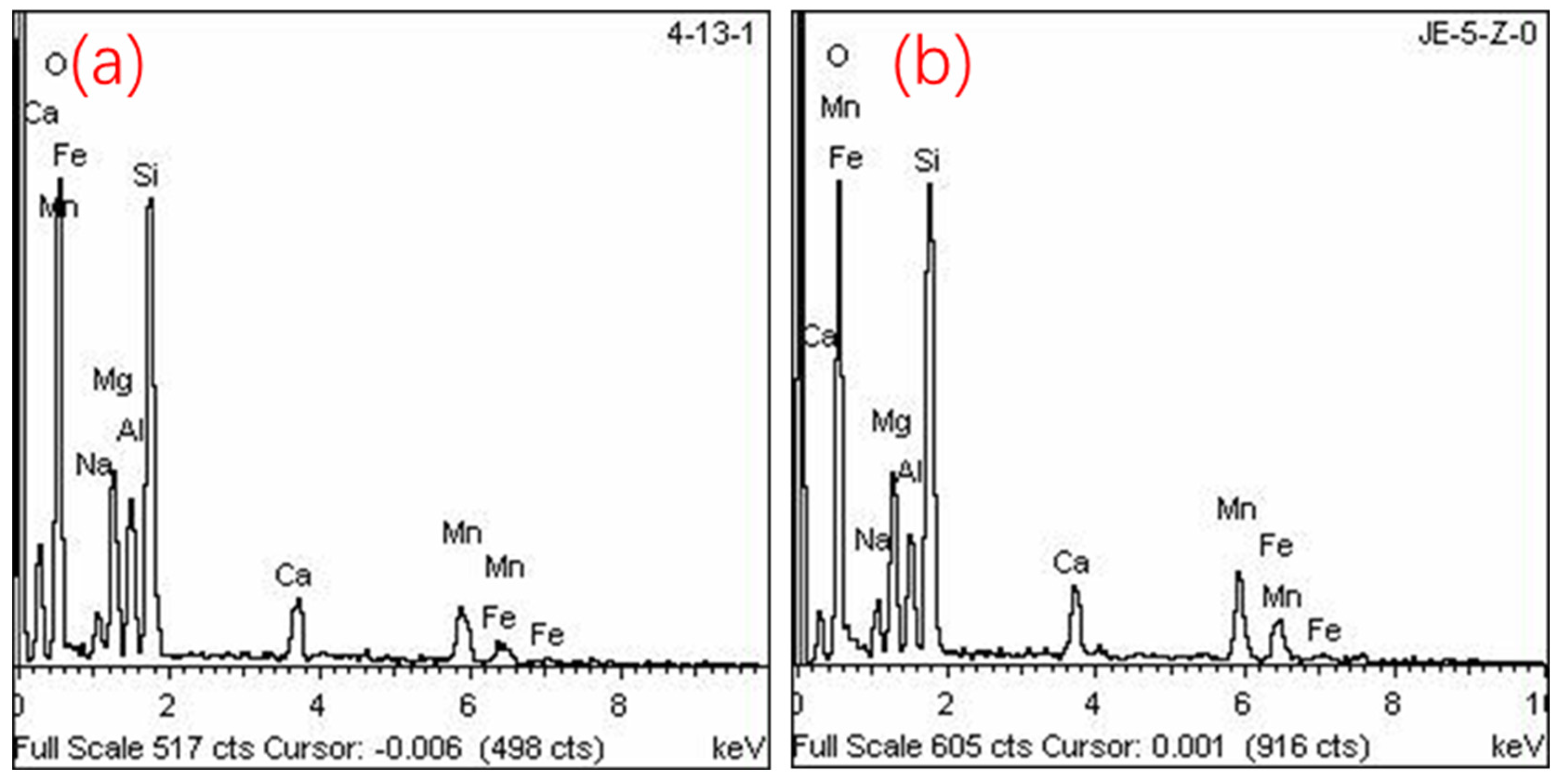
Comparative EDS analysis was carried out on several slag powder samples to examine the relative residual nickel contents. For JE-2 and JE-3 slags (Figure 8), no characteristic Ni peaks were detected in the EDS spectra, indicating that the residual Ni contents in these two slags were low. In contrast, the EDS spectra of JE-6 slag (Figure 9) clearly exhibited Ni peaks, suggesting a substantially higher residual Ni content. This qualitative EDS observation is consistent with the chemical analysis results presented in Table 1, which show Ni contents of 0.021%, 0.24%, and 4.80% in JE-2, JE-3, and JE-6 slags, respectively. The significantly higher Ni loss in JE-6 slag is attributed to the insufficient reduction depth and short smelting time (45 min) of Heat 6, which limited the settling and separation of nickel-bearing droplets from the slag phase.
Figure 8.
(a) Slag spectrum of JE-2; (b) slag spectrum of JE-3.
Figure 9.
Twice spectral results of JE-6 slag. (a) JE-6 slag- Sample 1, (b) JE-6 slag- Sample 2.
The reduction smelting results of the third run were relatively satisfactory; therefore, microscopic observation of polished sections and SEM analysis of the key slag phases were carried out on the JE-3 slag. The structural features of the massive JE-3 slag are shown in Figure 10.
Figure 10.
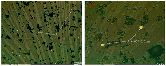
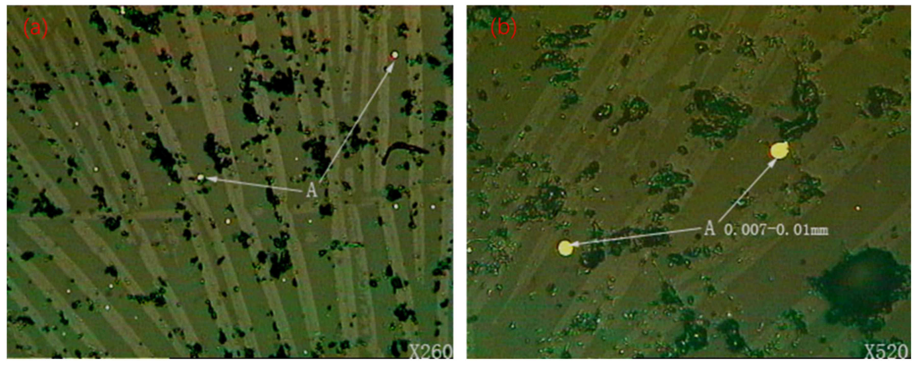
(a) Structural characteristics of JE-3 slag; (b) droplet nickel matte in JE-3 slag.
As shown in Figure 10, elongated columnar crystals of olivine are observed in the matrix phase, while the very fine-grained matte phase (A) is dispersed in the matrix phase in the form of droplets. The droplet-like matte in the JE-3 slag generally has a particle size of <10 μm. In terms of the JE-3 slag, the amount of matte remaining in the slag is very limited. SEM analysis was also performed on the slag, and the results are presented in Figure 11.
Figure 11.
(a) Back-scattered electron scanning image of JE-3 slag; (b) olivine columnar crystals in the matrix.
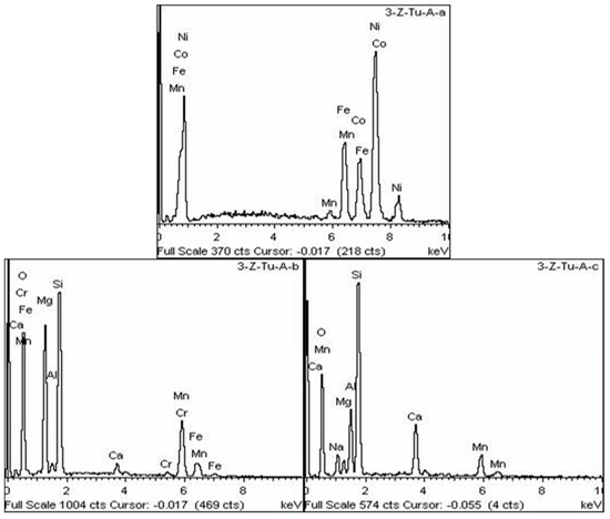
Figure 12 shows the BSE scanning image of the metal particles and slag phases in the slag, along with the EDS spectra for analysis points A, B, and C.
Figure 12.
Component energy spectra of analysis points A, B and C.
EDS analysis at point A reveals that the entrained alloy phase in the slag exhibits a multi-component characteristic; the EDS spectrum at point B indicates that it is manganese olivine, and the spectrum at point C shows a matrix phase of complex composition. Combined with microscopic identification and SEM-EDS analysis, a tentative compositional difference was observed between the alloy phase in the crude nickel and the entrained alloy droplets in the slag. The alloy phase in the bulk crude nickel, as confirmed by both XRD and SEM-EDS, is predominantly Ni with only minor amounts of Co and Fe. In contrast, the EDS spectrum of an entrained alloy droplet in the JE-3 slag (point A in Figure 12) suggests that this particular droplet contains relatively higher amounts of Fe, Co, and Mn. However, it should be emphasized that this comparison is based on qualitative EDS analysis of a limited number of particles and should therefore be regarded as a preliminary observation rather than a definitive conclusion. A more rigorous quantitative comparison, involving EDS mapping or systematic multiple-point analyses of a statistically meaningful number of particles, would be required to confirm the compositional difference. If confirmed, the observed trend could be rationalized by the different cooling histories of the bulk crude nickel (slow cooling in the furnace) versus the entrained droplets (rapid quenching in the slag), as well as the local equilibrium between the droplets and the surrounding silicate melt, which may favor the partitioning of Mn and Fe into the metallic phase under the specific micro-environment of the slag.
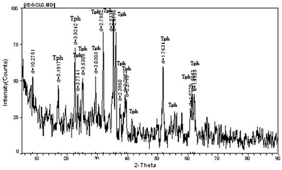
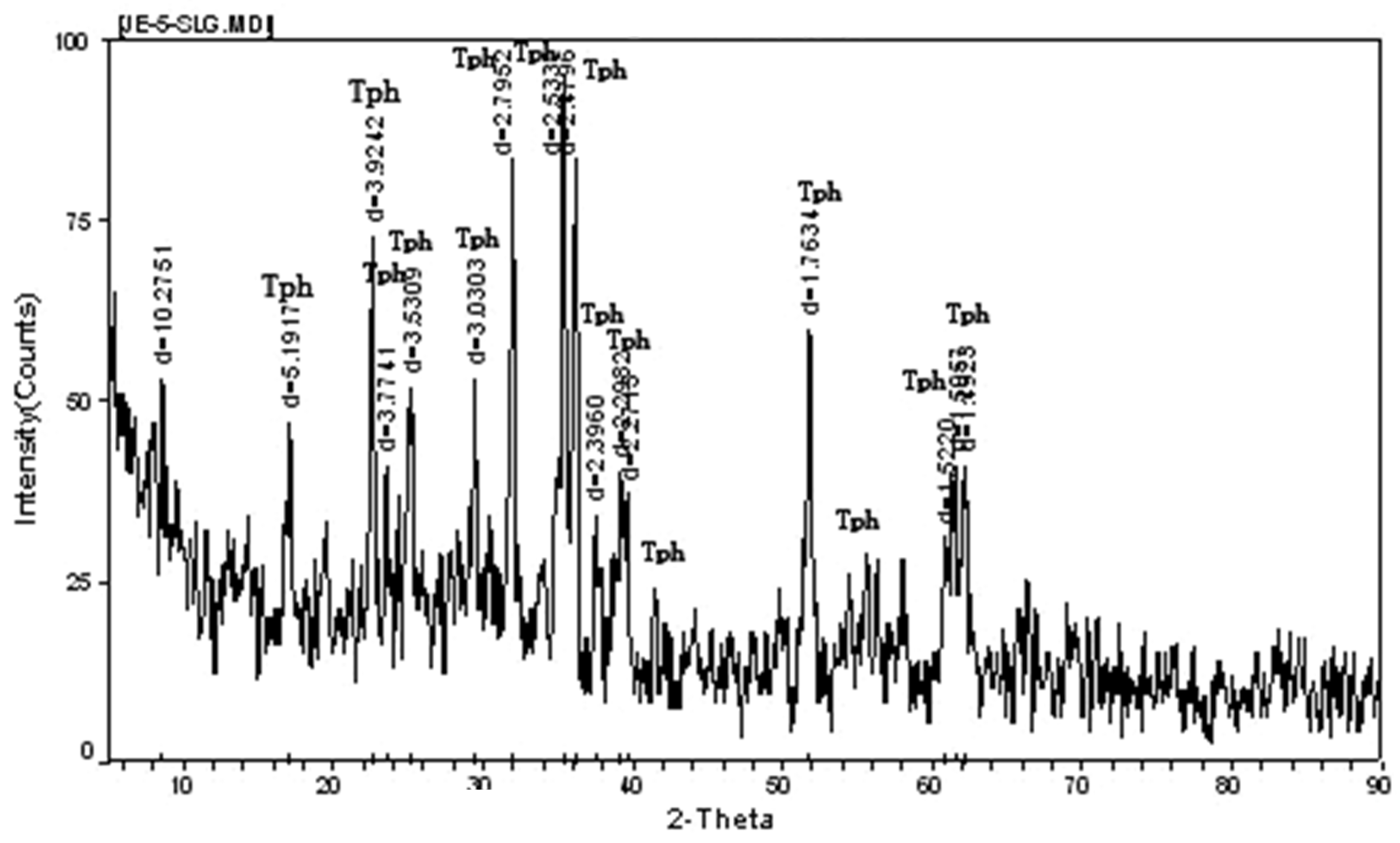
X-ray diffraction analysis of the JE-5 slag sample (Figure 13) indicates that the main identifiable phase is manganese–magnesium olivine (JCPDS card No. 19-0773 for tephroite, Mn2SiO4, and No. 34-0189 for forsterite, Mg2SiO4). However, due to the relatively low degree of crystallization of the matrix, the diffraction peaks appear diffuse, suggesting that the majority consists of glass phases with complex compositions. A few additional weak peaks (e.g., at 2θ ≈ 34.5° and 42.1°) could not be definitively assigned to any specific crystalline phase, likely due to their low intensity and the presence of a significant amorphous background, which may obscure minor phases. Therefore, the phase identification for these weak peaks remains uncertain. Overall, the slag contains very little matte, and its particle size is fine. The absence of discrete Ni- or Co-bearing crystalline phases in the XRD pattern (Figure 13), combined with EDS evidence of their spatial association with the Si–O-rich matrix, suggests that the residual Ni and Co are finely disseminated in the silicate glass phase. This mode of occurrence is consistent with previous findings on nickel smelter slags, where Ni and Co were reported to be hosted primarily in silicate phases (e.g., olivine and glass) rather than as independent minerals [29,30]. Such fine dissemination makes recovery by mechanical beneficiation inherently difficult.
Figure 13.
Diffraction spectrum of JE-5 slag (Tph-(Mn, Mg)2SiO4).
4. Conclusions
In this study, the pre-reduced calcine derived from nickel–cobalt hydroxide precipitate (MHP) was smelted in a 40 kVA semi-industrial electric arc furnace to systematically investigate the migration behaviors of typical impurity elements (S, Mn, and Zn) and their effects on crude nickel quality. Under the optimized conditions (pre-reduction at 900 °C and smelting at 1550 °C), a crude nickel product with a nickel grade exceeding 80% and a nickel recovery of approximately 98% was consistently obtained. The sulfur in the charge was predominantly distributed into the crude nickel phase (44.36–83.66% of total S), with only a minor fraction (1.26–1.38%) reporting to the slag, while the remainder was volatilized into flue gas, dust, or retained in the furnace. Manganese exhibited a strong tendency to be rejected from the crude nickel; under moderate reducing conditions, the manganese content in crude nickel could be kept below 0.2%, corresponding to a manganese removal efficiency from the metallic phase exceeding 99%. In terms of mass distribution, approximately 63–64% of the total manganese in the charge distributed into the slag, while the rest was distributed between flue gas, dust, and furnace retention. Zinc showed a volatilization rate exceeding 90%, and its residual content in crude nickel could be maintained below 0.1% under proper reduction control. Phase analysis confirmed that the crude nickel consisted of a Ni-based alloy and Ni3S2, while the slag was dominated by (Mn,Mg)2SiO4 olivine and a silicate glass phase.
This study focused on impurity elements that are detrimental to the electrorefining process, rather than on all metallic components. Cobalt, although co-enriched with nickel in the alloy phase, is a valuable product component and was not classified as an impurity. Iron and aluminum, owing to their strong slag-forming tendency and negligible partitioning into the metallic phase, were also excluded from this impurity-oriented investigation. The semi-industrial test results not only provide quantitative guidance for optimizing key parameters such as reduction intensity and smelting duration in MHP electric furnace smelting, but also offer practical implications for quality control of the feed material for subsequent electrorefining. Furthermore, the quantitative distribution of cobalt and the detailed mineralogical occurrence of residual Ni and Co in the slag warrant further investigation, which represents a potential direction for recovering these valuable metals from smelter slag.
Author Contributions
Conceptualization, H.W., X.Z. (Xiaoping Zou); validation, X.Z. (Xiaoping Zou); formal analysis, X.M., H.Z., X.Z. (Xiaobing Zhang); investigation, X.Z. (Xiaoping Zou), H.W.; resources, H.W.; Data curation, X.Z. (Xiaobing Zhang); writing—original draft preparation, X.Z. (Xiaoping Zou), H.Z.; writing—review and editing, H.Z., X.Z. (Xiaoping Zou); visualization, X.M. and H.Z.; supervision, H.Z.; project administration, H.Z.; funding acquisition, X.Z. (Xiaoping Zou). All authors have read and agreed to the published version of the manuscript.
Funding
This research was funded by the National Science and Technology Major Project (2025ZD0611003). The APC was funded by the Technical Center for Pyrometallurgy, Engineering Company, BGRIMM Technology Group, Beijing 100160, China.
Data Availability Statement
The original contributions presented in this study are included in the article. Further inquiries can be directed to the corresponding author.
Conflicts of Interest
All authors were employed by the Technical Center for Pyrometallurgy, Engineering Company, BGRIMM Technology Group, Beijing 100160, China. The authors declare that this study received funding from BGRIMM Technology Group. The funder was not involved in the study design, collection, analysis, interpretation of data, the writing of this article or the decision to submit it for publication.
References
- Tian, Q.H.; Li, Z.C.; Wang, Q.M.; Wang, S.S.; Guo, X.Y. Present Situation of Laterite Nickel Ore rResources and Research Progress of Smelting Technology. Trans. Nonferrous Met. Soc. China 2023, 33, 2975–2997. [Google Scholar]
- Fan, Q.; Yuan, S.; Wen, J.; He, J. Review on Comprehensive Utilization of Nickel Laterite Ore. Miner. Eng. 2024, 218, 109044. [Google Scholar] [CrossRef] [Scilit]
- Marzoughi, O.; Pickles, C.A. Solid State Reduction and Magnetic Separation of Nickeliferous Laterite Ores: Review and Analysis. J. Ind. Eng. Chem. 2024, 140, 65–87. [Google Scholar] [CrossRef] [Scilit]
- Basuhi, R.; Bhuwalka, K.; Moore, E.A.; Diersen, I.; Malik, R.H.; Young, E.; Billy, R.G.; Stoner, R.; Ceder, G.; Müller, D.B.; et al. Clean Energy Demand Must Secure Sustainable Nickel Supply. Joule 2024, 8, 2960–2973. [Google Scholar] [CrossRef] [Scilit]
- Sun, J.; Zhou, H.; Huang, Z. The Future Nickel Metal Supply for Lithium-Ion Batteries. Green Chem. 2024, 26, 6926–6943. [Google Scholar] [CrossRef] [Scilit]
- Chen, K.Z.; Zhang, W.J.; Li, J.; Wu, W.W.; Tong, X. Research Status and Prospect of Lateritic Nickel Ore Smelting Process. Chin. J. Rare Met. 2025, 49, 432–447. [Google Scholar]
- Wang, S.; Jiang, Y.; Zheng, F.Q.; Chen, F.; Yang, L.Z.; Guo, Y.F. Development of pyrometallurgical technology of laterite nickel ore. China Metall. 2021, 31, 1–7. [Google Scholar]
- Pickles, C.A.; Anthony, W. Thermodynamic Modelling of the Reduction of a Saprolitic Laterite Ore by Methane. Miner. Eng. 2018, 120, 47–59. [Google Scholar] [CrossRef] [Scilit]
- Pickles, C.A.; Forster, J.; Elliott, R. Thermodynamic Analysis of the Carbothermic Reduction Roasting of a Nickeliferous Limonitic Laterite Ore. Miner. Eng. 2014, 65, 33–40. [Google Scholar] [CrossRef] [Scilit]
- Çoban, B.; Baş, A.D. HPAL of a Lateritic Nickel Ore: An Investigation on the Relationship between Nickel and Cobalt Extraction and Acid Consumption. Miner. Eng. 2024, 218, 109014. [Google Scholar] [CrossRef] [Scilit]
- Kaya, Ş.; Topkaya, Y.A. High Pressure Acid Leaching of a Refractory Lateritic Nickel Ore. Miner. Eng. 2011, 24, 1188–1197. [Google Scholar] [CrossRef] [Scilit]
- Zhang, Z.F.; Zhang, W.B.; Zhang, Z.G.; Chen, X.F. Nickel Extraction from Nickel Laterites: Processes, Resources, Environment and Cost. China Geol. 2025, 8, 187–213. [Google Scholar] [CrossRef] [Scilit]
- Guo, X.Y.; Shi, W.T.; Li, D.; Tian, Q.H. Leaching Behavior of Metals from Limonitic Laterite Ore by High Pressure Acid Leaching. Trans. Nonferrous Met. Soc. China 2011, 21, 191–195. [Google Scholar] [CrossRef] [Scilit]
- Shao, S.; Ma, B.Z.; Wang, X.; Zhang, W.J.; Chen, Y.Q.; Wang, C.Y. Nitric Acid Pressure Leaching of Limonitic Laterite Ores: Regeneration of HNO3 and Simultaneous Synthesis of Fibrous CaSO4·2H2O By-products. J. Cent. South Univ. 2020, 27, 3249–3258. [Google Scholar] [CrossRef] [Scilit]
- He, F.; Ma, B.Z.; Wang, C.Y.; Ma, Y.T.; Asselin, E.; Chen, Y.Q.; Zhang, W.J.; Zhao, J. Microwave Pretreatment for Enhanced Selective Nitric Acid Pressure Leaching of Limonitic Laterite. J. Cent. South Univ. 2021, 28, 3050–3060. [Google Scholar] [CrossRef] [Scilit]
- Ma, B.; Yang, W.; Yang, B.; Wang, C.; Chen, Y.; Zhang, Y. Pilot-Scale Plant Study on the Innovative Nitric Acid Pressure Leaching Technology for Laterite Ores. Hydrometallurgy 2015, 155, 88–94. [Google Scholar] [CrossRef] [Scilit]
- Pandey, N.; Tripathy, S.K.; Patra, S.K.; Jha, G. Recent Progress in Hydrometallurgical Processing of Nickel Lateritic Ore. Trans. Indian Inst. Met. 2023, 76, 11–30. [Google Scholar] [CrossRef] [Scilit]
- Stanković, S.; Stopić, S.; Sokić, M.; Marković, B.; Friedrich, B. Review of the Past, Present, and Future of the Hydrometallurgical Production of Nickel and Cobalt from Lateritic Ores. Metall. Mater. Eng. 2020, 26, 199–208. [Google Scholar] [CrossRef] [Scilit] [PubMed]
- Shen, Y.; Wang, H.; Zhang, L.; Zhou, L.; Fu, C.; Jin, K.H.; Fang, M.; Wang, J. Research on the Short-Process of Leaching and Semi-Extraction Method of Nickel-Cobalt from Mixed Hydroxide Precipitate (MHP) to Prepare Battery Grade Products. Hydrometallurgy 2025, 233, 106446. [Google Scholar] [CrossRef] [Scilit]
- Clark, S.J.; Donaldson, J.D.; Khan, Z.I. Heavy Metals in the Environment. Part VI: Recovery of Cobalt Values from Spent Cobalt/Manganese Bromide Oxidation Catalysts. Hydrometallurgy 1996, 40, 381–392. [Google Scholar] [CrossRef] [Scilit]
- Williams, C.; Hawker, W.; Vaughan, J.W. Selective Leaching of Nickel from Mixed Nickel Cobalt Hydroxide Precipitate. Hydrometallurgy 2013, 138, 84–92. [Google Scholar] [CrossRef] [Scilit]
- Chong, S.; Hawker, W.; Vaughan, J. Selective Reductive Leaching of Oxidised Cobalt Containing Residue. Miner. Eng. 2013, 54, 82–87. [Google Scholar] [CrossRef] [Scilit]
- Kinanti, N.L.D.W.; Xu, K.; Hu, Z.; Cheng, Q.; Yu, D. Life Cycle Assessment of Nickel Laterite Refining to Battery Materials Intermediates in Indonesia: A Case Study. Hydrometallurgy 2026, 242, 106712. [Google Scholar] [CrossRef] [Scilit]
- Xing, J.; Leng, H.G.; Han, B.S.; Yang, M.Y.; Yu, Z.; Jia, H.X. Metallurgical Technology Situation and Research Progress of Laterite Nickel Ore. Nonferrous Min. Metall. 2021, 37, 26–32. [Google Scholar]
- Oxley, A.; Smith, M.E.; Caceres, O. Why Heap Leach Nickel Laterites? Miner. Eng. 2016, 88, 53–60. [Google Scholar] [CrossRef] [Scilit]
- Keskinkilic, E. Nickel Laterite Smelting Processes and Some Examples of Recent Possible Modifications to the Conventional Route. Metals 2019, 9, 974. [Google Scholar] [CrossRef] [Scilit]
- Peng, S. Application of Side-Submerged Combustion Smelting (SSC) Process in Recovery of Lead Smelting By-Products. J. Phys. Conf. Ser. 2024, 2738, 012025. [Google Scholar] [CrossRef] [Scilit]
- Zou, X.P.; Jiang, K.X.; Wang, H.B.; Jiang, Y.P.; Deng, C.Q.; Huang, S.; Chen, L.L.; Zhang, X.B. Method for Producing High-Grade Nickel Matte from Nickel-Cobalt Enriched Material and High-Grade Nickel Matte. CN 202210370855.8, 24 June 2026. [Google Scholar]
- Ettler, V.; Kvapil, J.; Šebek, O.; Johan, Z.; Mihaljevič, M.; Ratié, G.; Garnier, J.; Quantin, C. Leaching behaviour of slag and fly ash from laterite nickel ore smelting (Niquelândia, Brazil). Appl. Geochem. 2016, 64, 118–127. [Google Scholar] [CrossRef] [Scilit]
- Vítková, M.; Ettler, V.; Johan, Z.; Kribek, B.; Sebek, O.; Mihaljevic, M. Primary and secondary phases in copper-cobalt smelting slags from the Copperbelt Province, Zambia. Mineral. Mag. 2010, 74, 581–600. [Google Scholar] [CrossRef] [Scilit]

Disclaimer/Publisher’s Note: The statements, opinions and data contained in all publications are solely those of the individual author(s) and contributor(s) and not of MDPI and/or the editor(s). MDPI and/or the editor(s) disclaim responsibility for any injury to people or property resulting from any ideas, methods, instructions or products referred to in the content. |
© 2026 by the authors. Licensee MDPI, Basel, Switzerland. This article is an open access article distributed under the terms and conditions of the Creative Commons Attribution (CC BY) license.