


Abstract
In this work, conventional friction stir lap welding (FSLW), self-riveting FSLW (R-FSLW) and ultrasonic-assisted R-FSLW (UR-FSLW) were employed to join dissimilar AA6061 and AZ31 alloys. The relatively thick Al-Mg intermetallic compound (IMC) layer provided limited metallurgical bonding, causing the FSLW joint to fail in a brittle manner at a low tensile shear force of 875 N. The self-riveting introduced additional mechanical interlocking: the R-FSLW joint, featuring AA6061 rivets, exhibited a 22% increase in tensile shear force compared with the FSLW joint. Nevertheless, cracks formed along the thick Al-Mg IMC layer around the AA6061 rivets, which retained the brittle fracture characteristic. In contrast, ultrasonic assistance not only improved the rivet filling rate (reducing the unfilled area from 0.83 mm2 to 0.61 mm2) but also suppressed Al-Mg IMC layer growth and eliminated cracks. Moreover, ultrasonic assistance increased the stored energy and promoted material flow, refining the grains in the nugget zone (NZ) and thereby raising the average hardness of NZ. Consequently, with AA6061 rivets and refined microstructures, the UR-FSLW joint delivered a tensile shear force of 1280 N and an elongation double that of the FSLW joint, accompanied by a fracture mode transition from brittle to ductile-brittle.
1. Introduction
Owing to their high specific strength and favorable formability, lightweight Al and Mg alloys are increasingly utilized in the aviation, automotive, and marine sectors, as part of efforts to meet critical demands of energy saving and emission reduction [1,2]. However, joining them remains a challenge for practical applications, primarily because conventional fusion welding methods (e.g., GMAW, GTAW, and laser welding) involve excessive heat input [3]. Such high heat input not only causes melting/solidification defects (e.g., porosity and hot cracking) [4] but also raises the welding temperature above the Al-Mg eutectic point, thereby promoting a thick and brittle IMC layer that severely deteriorates the joint performance [5,6]. To circumvent the above issues, friction stir welding (FSW), a solid-state welding method with low heat input, has been increasingly adopted for joining dissimilar Al and Mg alloys [7]. Its lap variant, friction stir lap welding (FSLW), is also widely employed to produce dissimilar Al/Mg lap joints [8,9,10].
The quality of dissimilar Al/Mg FSLW joints generally relies on both mechanical interlocking from interfacial Al/Mg mixing and metallurgical bonding via the formation of an Al-Mg IMC layer with suitable thickness [11,12]. However, achieving simultaneous optimization of both factors through conventional welding parameter adjustment alone is difficult. For instance, Zhao et al. [13] reported that increasing the rotational speed of the stir tool enhanced the interfacial Al/Mg mixing but inevitably thickened the Al-Mg IMC layer. Similarly, He et al. [14] found that a threaded stir tool design improved interfacial Al/Mg mixing while also promoting Al-Mg IMC layer overgrowth.
To overcome the above trade-off, researchers have turned to externally assisted FSLW techniques, which can be broadly categorized into heat source assistance (e.g., arc-assisted, laser-assisted, and current-assisted methods) and ultrasonic assistance [15]. Studies indicate that while heat source assistance can enhance material mixing and metallurgical reactions by supplying additional energy, it simultaneously causes grain coarsening and joint softening due to excessive heat input, severely limiting its applicability [16,17]. In contrast, ultrasonic assistance lowers the yield and flow stresses of materials during welding, thereby facilitating material mixing while suppressing grain coarsening and IMC layer thickening [18,19]. Moreover, the ultrasonic assistance method does not require complex equipment modification and is fully compatible with existing friction stir welding platforms, suggesting good potential for industrial implementation. These benefits render ultrasonic assistance particularly well-suited for the dissimilar Al/Mg FSLW [20].
Despite the improved interfacial Al/Mg mixing achieved by ultrasonic assistance, relying solely on this single energy field remains insufficient to overcome the inherent morphological constraints of the Al/Mg interface, thus limiting the development of strong mechanical interlocking. Our previous study bears this out: the interfacial Al/Mg mixing length of the FSLW joint increased only from 3.1 to 3.3 mm by the application of ultrasonic assistance, a marginal gain insufficient to appreciably improve mechanical interlocking [21]. In fact, the positive effect of ultrasonic assistance is mainly reflected in the microstructural evolution [18].
To further enhance the mechanical interlocking, Huang et al. [22] proposed self-riveting friction stir lap welding (R-FSLW), which utilized friction stir heat and mechanical action to create rivet-like structures. Using this method, Huang et al. [23] and Chen et al. [24] successfully produced high-quality dissimilar Al/Fe FSLW joints, attributing the joint strength to the synergistic effect of mechanical riveting and metallurgical bonding. Nevertheless, R-FSLW primarily affects the macrostructure of the joint, with only a minor influence on microstructural features such as grain size and IMC layer thickness.
As mentioned above, the ultrasonic assistance and self-riveting each offer distinct advantages and limitations in strengthening the dissimilar Al/Mg FSLW joints: ultrasonic assistance excels at promoting metallurgical bonding (e.g., grain and IMC layer refinement) but contributes little to improving mechanical interlocking; self-riveting effectively enhances mechanical interlocking yet fails to optimize microstructures. Therefore, integrating both ultrasonic assistance and self-riveting into the dissimilar Al/Mg FSLW process is expected to simultaneously improve mechanical interlocking (macrostructures) and metallurgical bonding (microstructures), overcoming the limitations inherent in each individual technique.
In this study, three welding processes, conventional FSLW, R-FSLW, and ultrasonic-assisted R-FSLW (UR-FSLW), were employed to join dissimilar Al and Mg alloys. The macro/microstructural features and mechanical properties of the resulting joints were systematically characterized. Unlike earlier work that focused on the individual technique, the present study aims to elucidate the coupling effects of ultrasonic assistance and self-riveting, providing new insights into how their synergy influences both mechanical interlocking and metallurgical bonding in the dissimilar Al/Mg FSLW joint.
2. Materials and Methods
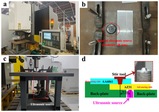
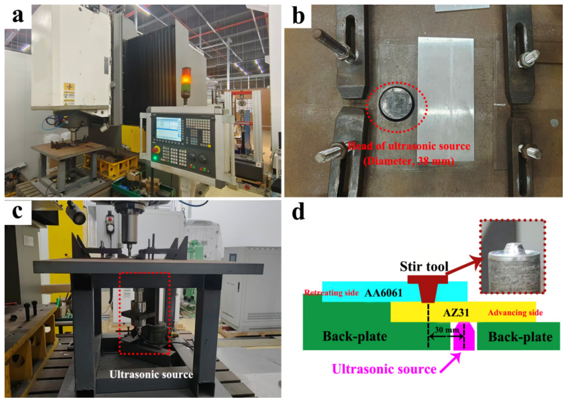
In this study, 2 mm thick rolled plates of AA6061 (Al) and AZ31 (Mg) were used as the base metals, with their nominal chemical compositions listed in Table 1. The FSLW equipment (HT-JM25×15/2, AEE, Suzhou, China) is shown in Figure 1a, and the detailed views of ultrasonic source (i.e., ultrasonic-assisted facility) are provided in Figure 1b,c. The ultrasonic source was fixed beneath the back-plate, with its head inserted into the back-plate through a pre-fabricated hole. The ultrasonic head had a diameter of 38 mm, and the ultrasonic parameters were maintained constant, specifically at a power of 300 W, a frequency of 20 kHz and an amplitude of 20 μm. Figure 1d presents the schematic diagram for the conventional FSLW, R-FSLW and UR-FSLW. The AA6061 plate was placed on top of the AZ31 plate, and the ultrasonic source was pressed against the AZ31 plate (on the advancing side, AS). A distance of 30 mm was set between the ultrasonic source and the welding centerline. The ultrasonic source was switched on when ultrasonic assistance was required, and otherwise, it was turned off.
Table 1.
The nominal chemical compositions of AA6061 and AZ31 used in this study (wt.%).
Figure 1.
(a) The FSLW equipment; (b) the head of ultrasonic source; (c) the main view of ultrasonic source; (d) the FSLW/R-FSLW/UR-FSLW schematic.
The ultrasonic frequency and amplitude were primarily dictated by the fixed output specifications of the ultrasonic transducer system (ZJS-2000, FYCG, Hangzhou, China) used in this work, which operated at a resonant frequency of 20 kHz with nominal amplitude of 20 μm. This specific combination falls within the adopted standard configuration (20 kHz frequency and 10–25 μm amplitude) for ultrasonic welding of Al/Mg dissimilar joints in the literature [14,25]. The value of 300 W was determined through a series of preliminary screening tests (reported in our previous studies [18,26]): lower power inputs could not supply sufficient energy to activate effective material flow and bonding, whereas higher power levels generated severe impact effects that led to cracks. The suitable power setting of 300 W successfully yielded a defect-free joint while avoiding the drawbacks observed at elevated powers.
It should be noted that, for the R-FSLW and UR-FSLW processes, the straight-through holes (2.5 mm in diameter) were pre-drilled in the AZ31 plates with an interval of 15 mm before welding, and each plate contained 15 such holes. The stir tool, made of H13 steel, consisted of a flat shoulder (12 mm in diameter) and a conical pin (2 mm in length) with root and tip diameters of 5 mm and 3 mm, respectively. Constant welding parameters were adopted, including a rotational speed of 800 rpm, a welding speed of 50 mm/min, a plunge depth of 0.1 mm and a tool tilt angle of 1°. The welding parameters were also adopted from our previous systematic study on Al/Mg dissimilar friction stir welding [18], in which this parameter combination was demonstrated to produce sound joints with acceptable surface quality and mechanical properties.
Optical microscopy (OM, Olympus-DSX-500, Olympus, Tokyo, Japan) and scanning electron microscopy (FEI-Quanta-600, SEM, FEI, Portland, OR, USA) were used to characterize the macro/microstructures of dissimilar Al/Mg joints. The OM samples were ground, mechanically polished and etched with Keller`s reagent (HF:HCL:HNO3:H2O = 2:3:5:90 by volume). The SEM samples were only ground and mechanically polished to prevent the second-phase particles from being dislodged during etching. SEM imaging was performed in the secondary electron mode. The application of SEM was to analyze the morphologies of second-phase particles and IMC layer. The thickness of the IMC layer was measured with a rigorous statistical approach. For each detected region, the IMC layer thickness was measured on the representative high-magnification SEM image by taking more than 15 evenly spaced measurement lines along the entire IMC layer. It should be noted that the phase assignment of IMCs is primarily based on EDS stoichiometry (EDS, FEI-Quanta-600, FEI, Portland, OR, USA) and the literature comparison, as dedicated diffraction techniques were not performed for independent verification. Furthermore, electron backscattered diffraction (EBSD, FEI-Quanta-600, FEI, Portland, OR, USA) was also employed to quantify grain size and the fraction of high-angle grain boundaries (HAGBs) in the nugget zone (NZ). The EBSD samples were electropolished in a perchloric acid-ethanol solution (HCLO4:C2H5OH = 1:9 by volume). Specifically, the electropolishing was performed at a voltage of 19 V, a temperature of −30 °C, and a duration of 25 s. EBSD scanning was performed with a step size of 0.2 μm; meanwhile, low-angle grain boundaries (LAGBs, 2° < θ < 15°) and HAGBs (θ > 15°) were marked as white and black lines, respectively.
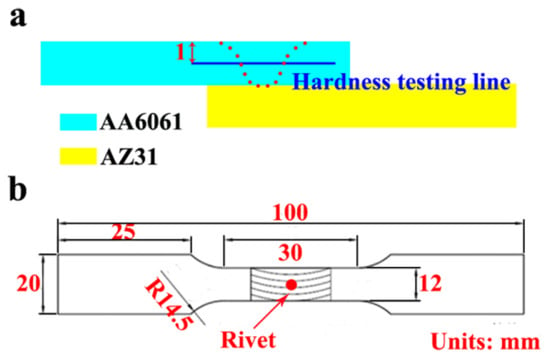
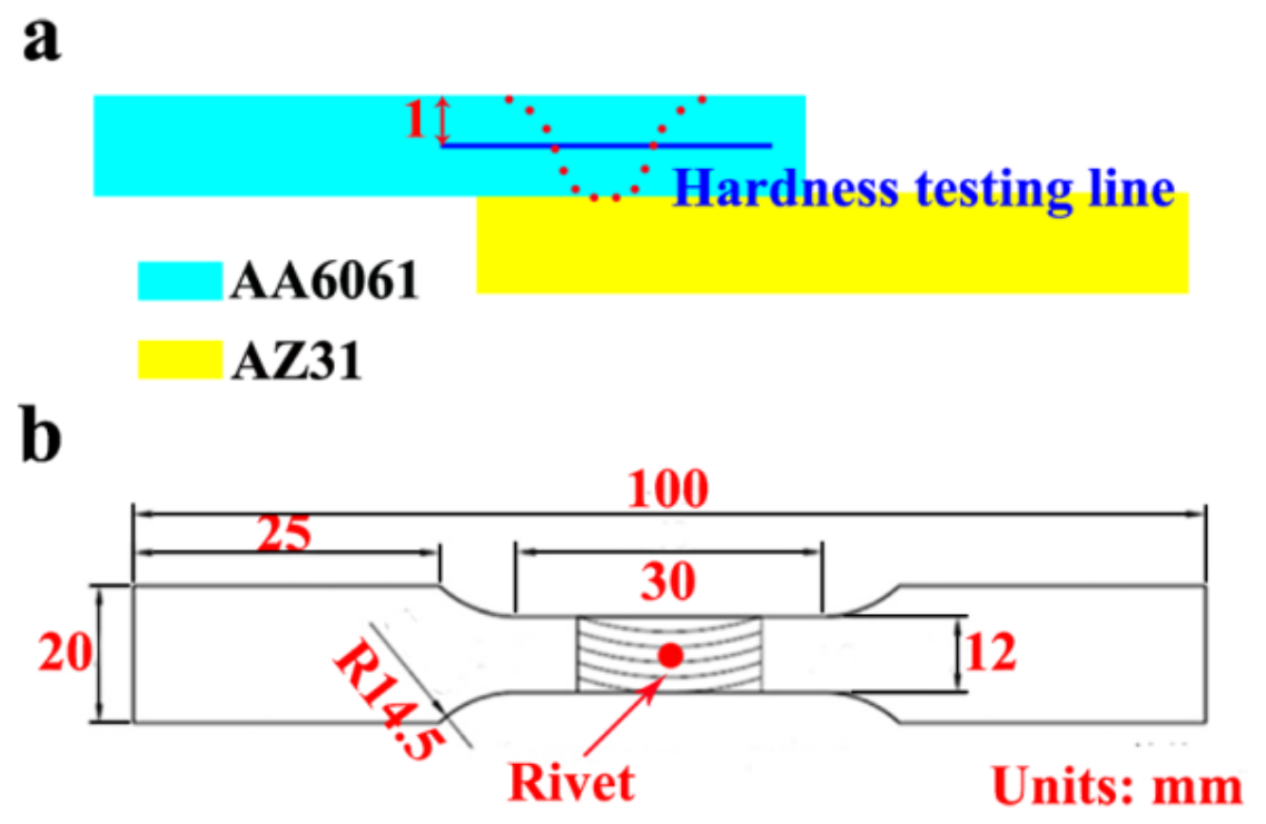
The mechanical properties of all dissimilar Al/Mg joints were assessed via the Vickers hardness and tensile shear tests. Hardness profiles across the joint were obtained using an Vickers hardness tester (HV, HV-1000Z, SCTMC, Shanghai, China). As illustrated in Figure 2a, the indentations were made along the mid-thickness line of upper AA6061 plates, from the retreating side (RS) to the AS. Each measurement line consisted of 40–50 points at 0.5 mm spacing, with a load of 50 gf and a dwell time of 5 s. The tensile shear specimens, each containing one aluminum rivet, were prepared perpendicular to the welding direction (see Figure 2b for dimensions). The tensile shear test was performed at a crosshead speed of 1.5 mm/min, and the ultimate tensile shear force was averaged from three repeated tests per joint. After the tensile shear test, the failure behavior was analyzed using SEM.
Figure 2.
The schematic diagrams of (a) Vickers hardness test and (b) tensile shear specimen.
3. Results and Discussion
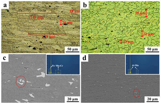
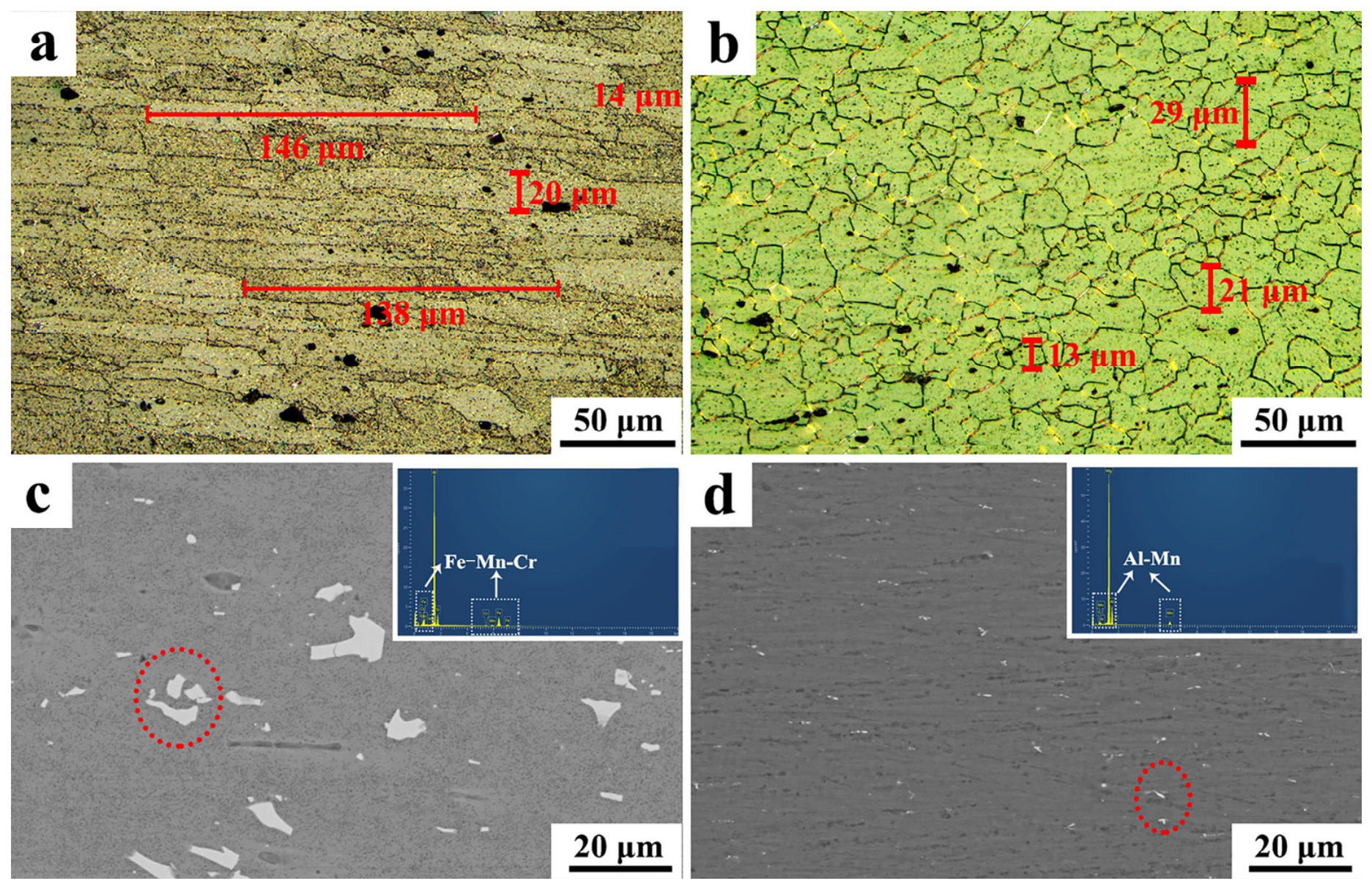
The initial microstructures of the base metals are shown in Figure 3. Specifically, AA6061 exhibits elongated grains (Figure 3a), whereas AZ31 exhibits nearly equiaxed grains (Figure 3b). The grain size was evaluated, and the specific measurement procedures are as follows: (1) for the elongated grains (AA6061), the length is defined as the maximum dimension measured parallel to the rolling direction, and the width is defined as the maximum dimension measured perpendicular to the rolling direction; (2) for the nearly equiaxed grains (AZ31), the diameters along two orthogonal directions are measured. To ensure statistical reliability, more than 50 grains with fully closed and distinct grain boundaries within the field of view were randomly selected, while grains intercepted by the image frame were excluded. Overall, both AA6061 and AZ31 exhibit coarse grains: the grains of AA6061 are approximately 100–150 μm in length and 10–30 μm in width, while those of AZ31 are isometric, ranging from 10 to 40 μm in size.
Figure 3.
The microstructures of base metals: the grains in (a) AA6061 and (b) AZ31; the second-phase particles in (c) AA6061 and (d) AZ31.
The second-phase particles are also present in both alloys, uniformly distributed throughout the matrix (Figure 3c,d). EDS analysis indicates that particles in AA6061 contain Fe, Mn and Cr, while those in AZ31 are rich in Al and Mn. According to Wu et al. [27] and Manjhi et al. [28], these phases in AA6061 and AZ31 are identified as Al(FeMnCr)Si and Al8Mn5, respectively. The second-phase particles in AA6061 are coarse (5–30 μm), whereas those in AZ31 are much finer, mostly below 3 μm. The particles are more abundant in AA6061 than in AZ31, which is probably due to the higher alloy content of AA6061.
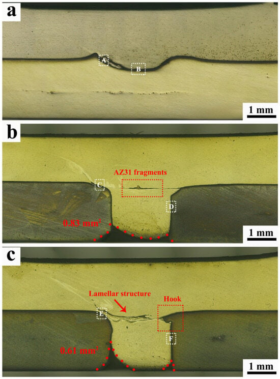
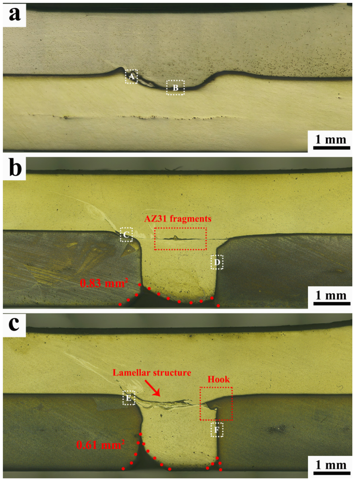
Figure 4 presents the cross-sectional views of all dissimilar Al/Mg joints. For the conventional FSLW joint (Figure 4a), the Al/Mg interface exhibits a curved morphology, resulting from the tool’s plunge and stirring action. In contrast, the R-FSLW joint shows two major differences (Figure 4b). Firstly, an AA6061 rivet is formed as the alloy fills the pre-drilled hole in the AZ31 plate; however, the hole is not completely filled, leaving an unfilled area of approximately 0.83 mm2. Secondly, the original pre-drilled hole becomes deformed, and the adjacent AZ31 material is fragmented and stirred into the NZ. The application of ultrasonic assistance induces the acoustoplastic effect, which further enhances the material flow during FSLW [29,30]. As a result, more AA6061 flows down into the pre-drilled hole, reducing the unfilled area to 0.61 mm2 (Figure 4c). Meanwhile, the deformation of the pre-drilled hole also becomes more pronounced due to the acoustic softening, resulting in the formation of a hook-like structure at the Al/Mg interface. Apart from that, more fragmented AZ31 material is stirred into the NZ, exhibiting a lamellar morphology. It is worth noting that the appearance of such a lamellar structure indicates sufficient material mixing [31], implying that the AZ31 fragments can rotate around the stir tool and become fully intermixed with AA6061.
Figure 4.
The macrostructures (i.e., the cross-sectional views) of (a) FSLW joint; (b) R-FSLW joint; (c) UR-FSLW joint.
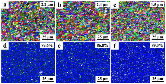
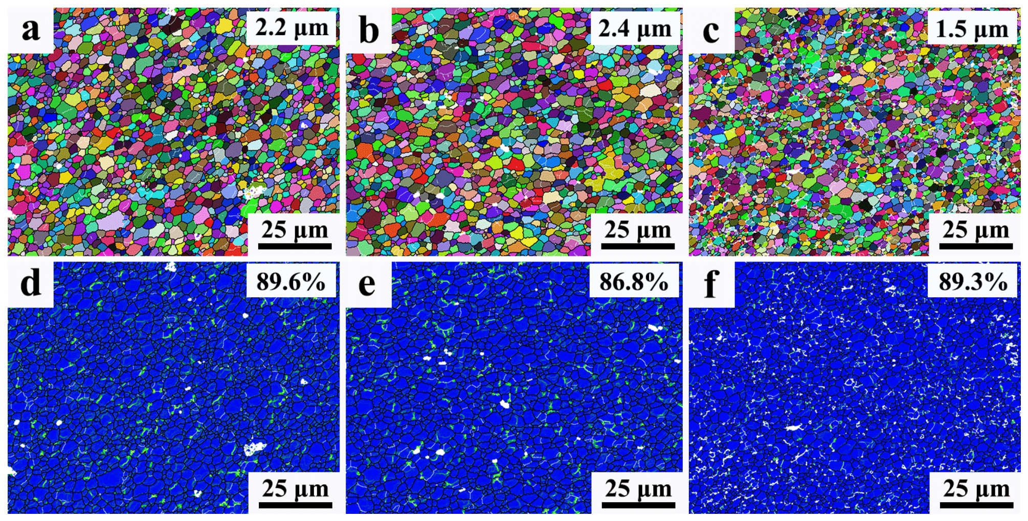
Figure 5 presents the grain evolutions in the NZ. Compared with the initial coarse grains in the base metals, the grains are refined through dynamic recrystallization (DRX) during FSLW [32]. As shown in Figure 5a,b, the average grain size of the FSLW joint is 2.2 μm, which is similar to that of the R-FSLW joint (2.4 μm). This similarity is mainly attributed to the comparable welding parameters employed. However, the UR-FSLW joint exhibits finer grains, with an average size of 1.5 μm, corresponding to a reduction of more than 30%. Based on the findings of Azimzadegan et al. [33], an inverse relationship exists between the DRX grain size and the strain rate. The application of ultrasonic assistance facilitates the material flow, thereby elevating the strain rate and contributing to grain refinement. Furthermore, the role of stored energy must also be taken into account. The grain size can be expressed as D = C × (G/NA)1/3, where D is the grain size, C is the material constant, NA is the nucleation rate and G is the growth rate. Both NA and G are positively correlated with the stored energy, while the former exhibits a greater sensitivity to changes in the stored energy than the latter [34]. Consequently, the ultrasonic energy raises the stored energy of NZ, which tends to promote nucleation over growth, ultimately resulting in finer grains in the UR-FSLW joint. Kernel Average Misorientation (KAM) analysis has also been employed to assess both the dislocation density and proportion of HAGBs. The results reveal a relatively low dislocation density in the NZ, which is attributed to the consumption of dislocations during DRX [35]. Nearly complete DRX is observed in all the dissimilar Al/Mg joints, where the HAGB fraction is above 85% (Figure 5d–f).
Figure 5.
The grain morphology in the NZ of (a) FSLW joint; (b) R-FSLW joint; (c) UR-FSLW joint; and the KAM information in the NZ of (d) FSLW joint; (e) R-FSLW joint; (f) UR-FSLW joint.
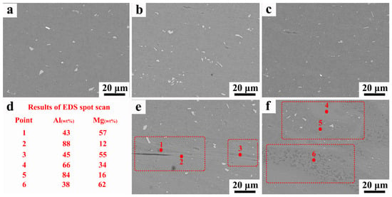
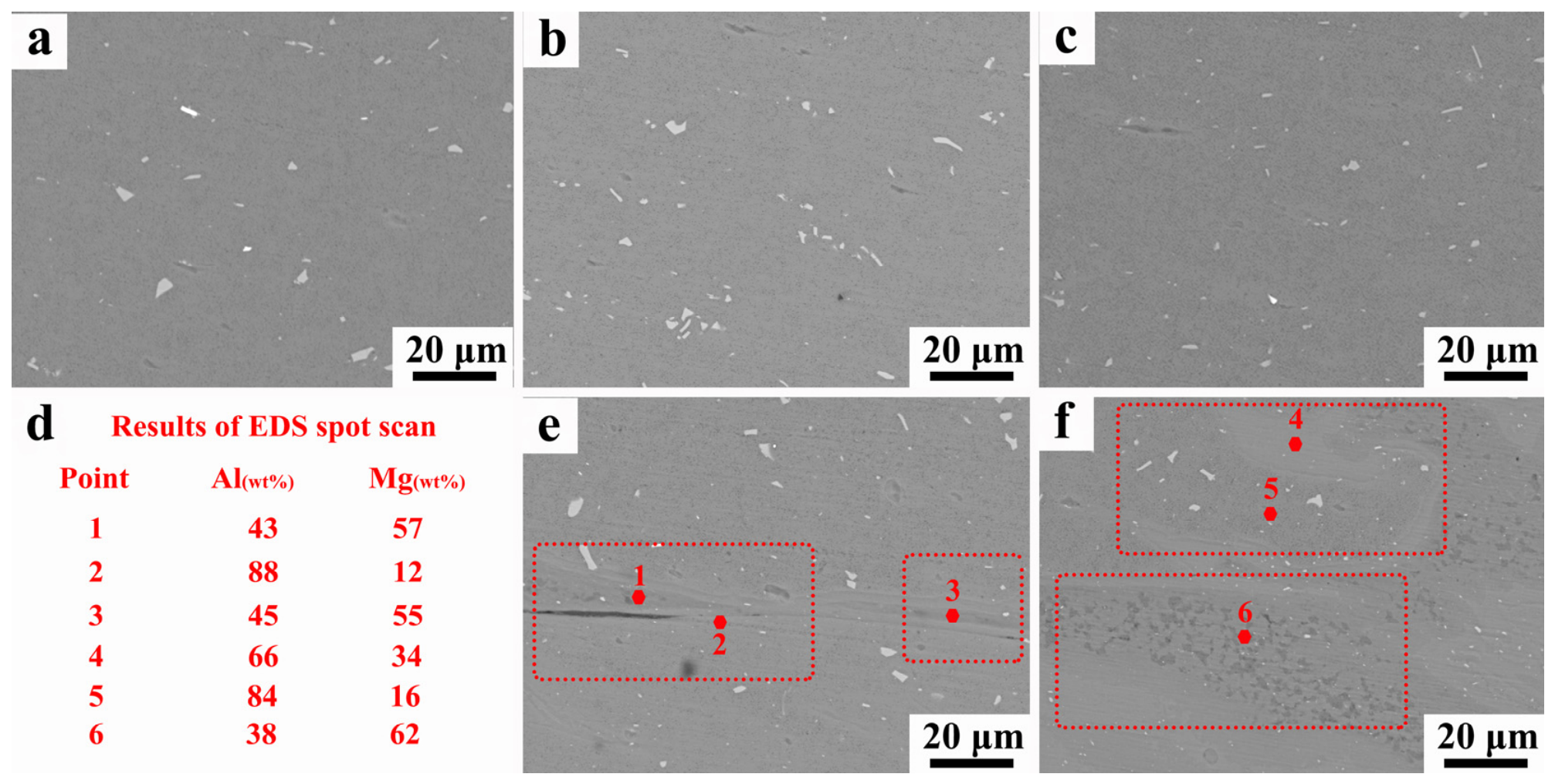
Figure 6 shows the second-phase particles and Al/Mg mixture in the NZ. Similar to the grain structure, the second-phase particles in the conventional FSLW joint are refined by the tool’s stirring action, with their average size decreasing to less than 5 μm (Figure 6a). These refined particles exert a Zener pinning effect on grain boundaries during the welding thermal cycle. Even though these particles are inherited from the base metals, their thermal stability at elevated temperatures allows them to effectively restrain grain boundary migration, thereby suppressing excessive grain growth and contributing to the retention of a relatively fine-grained structure in the nugget zone of all joints. Moreover, the importance of these particles is not limited to microstructural refinement; they also indirectly contribute to the mechanical performance of joints by preserving the fine-grained structure via Zener pinning (e.g., through the Hall–Petch strengthening effect). However, no significant difference in particle size is observed among the FSLW, R-FSLW and UR-FSLW joints (Figure 6b,c), because the particles smaller than a critical mean diameter resist further fragmentation [36]. As shown in Figure 6d–f, both the R-FSLW and UR-FSLW joints exhibit AZ31 fragments that have been mixed into the NZ through stirring. Chemical analysis of the above Al/Mg mixture region indicates the occurrence of a reaction between Al and Mg, leading to the formation of brittle Al-Mg IMCs. Combining the EDS compositional gradients and the reports of Refs [4,26,37,38], it can be inferred that the observed IMCs in this work are most likely attributed to the Al3Mg2 and Al12Mg17 phases. Furthermore, the application of ultrasonic assistance promotes more intensive Al/Mg mixing.
Figure 6.
The second-phase particles morphology in the NZ of (a) FSLW joint; (b) R-FSLW joint; (c) UR-FSLW joint; (d) the EDS spot scan and Al/Mg mixture morphology in the NZ of (e) R-FSLW joint and (f) UR-FSLW joint.
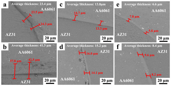
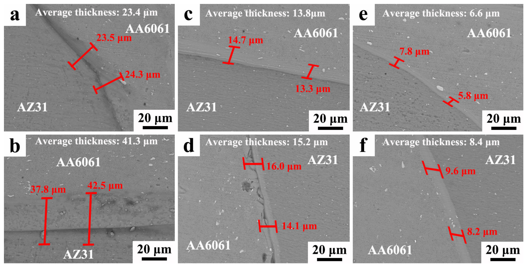
For the conventional FSLW joint, two typical regions (marked as A and B in Figure 4a) were selected for Al/Mg interface investigation, as shown in Figure 7a,b. The continuous and distinct Al-Mg IMC layer forms in these two regions, while the layer thickness in region B is considerably greater than that in region A. Region A refers to the peripheral region of the nugget zone adjacent to the thermo-mechanically affected zone, while region B refers to the center of the nugget zone. The statistical results show that the average IMC thickness in region A is 23.4 μm, whereas that in region B is 41.3 μm, indicating a clear spatial variation. This observed variation can be attributed to the thermal and material flow characteristics of heat input distribution during welding. Owing to intense material flow and thermal conduction, the material near the center of the nugget zone (region B) typically undergoes more severe plastic deformation, higher peak temperatures, and a longer residence time at elevated temperatures. These conditions provide stronger kinetic driving forces for atomic diffusion and consequently accelerate the growth of the IMC layer. In contrast, region A, located at the edge of the nugget zone, is subjected to a relatively lower peak temperature and a faster cooling rate, which effectively suppresses excessive IMC coarsening [19,39]. The formation of an Al-Mg IMC layer at the interface induces the metallurgical bonding of the FSLW joint. For the R-FSLW joint, regions C and D in Figure 4b were chosen for analysis. A continuous and distinct IMC layer is also visible at the Al/Mg interface in both regions. The IMC layer near the AS (region C) is sound (Figure 7c), whereas the layer adjacent to the AA6061 rivet (region D) exhibits cracks (Figure 7d). For the UR-FSLW joint, similar regions (E and F in Figure 4c) were examined, and the Al-Mg IMC layer remains continuous, and no cracks can be observed in either region. The detailed IMC layer thickness of all detected regions can be seen in Table 2.
Figure 7.
The Al/Mg mixture morphology of (a) region A and (b) B in the FSLW joint; (c) region C and (d) D in the R-FSLW joint; (e) region E and (f) F in the UR-FSLW joint.
Table 2.
The thickness of IMC layer in regions A to F.
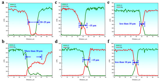
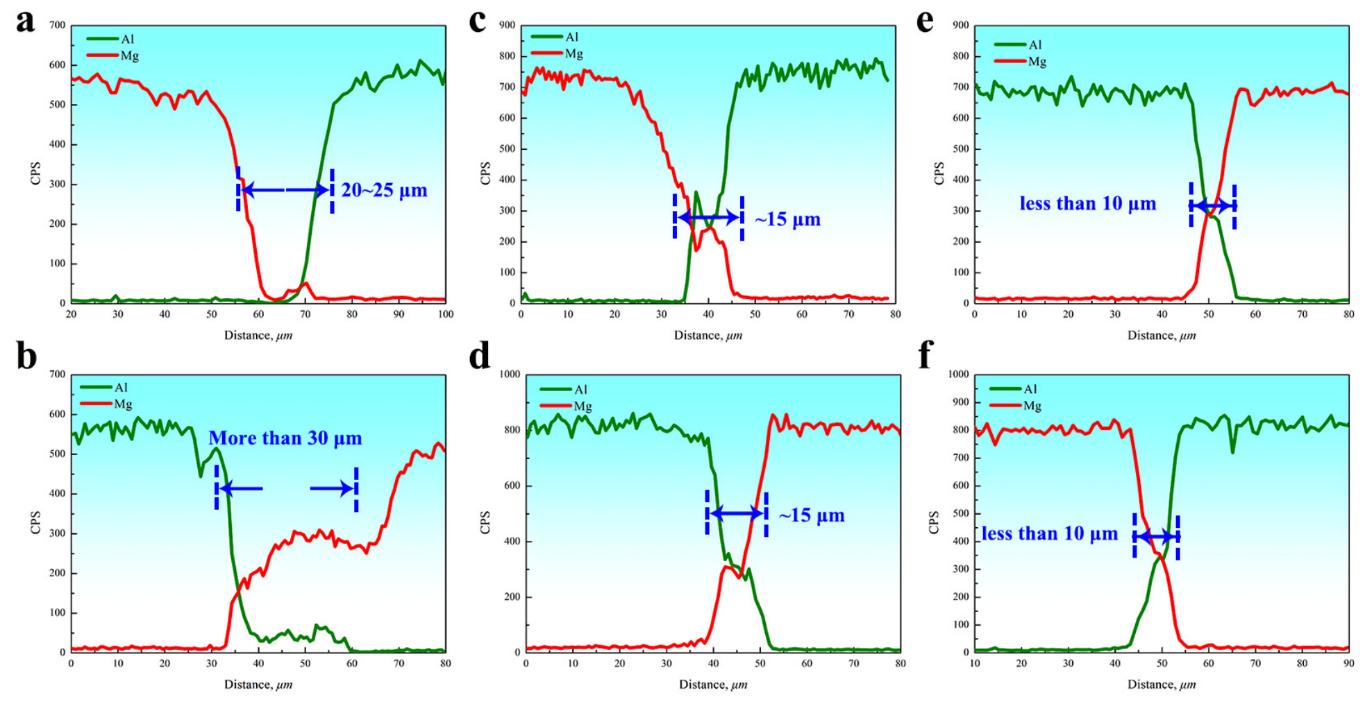
The EDS line scanning results (Figure 8) provide complementary evidence that supports accurate identification of the IMC layer boundaries. For the conventional FSLW joint, the Al/Mg interfacial diffusion is evident: the IMC layer thickness of region A is about 20–25 μm (Figure 8a) and that of region B reaches more than 30 μm (Figure 8b). By comparison, the IMC layer thickness of the R-FSLW joint decreases slightly to approximately 15 μm (Figure 8c,d). Nevertheless, this thickness remains considerable, and thus, the brittle nature of the IMC layer cannot be avoided. During formation of the AA6061 rivet, the material flow disrupts the IMC layer, inducing crack initiation in region D. A marked inhibition of IMC layer growth is observed for the UR-FSLW joint, yielding an average thickness less than 10 μm (Figure 8e,f). Under ultrasonic-assisted friction stir welding, the high-frequency vibration induces intense stirring and squeezing effects, which can mechanically fracture, disperse, and dilute the pre-formed brittle IMC layer into the surrounding matrix. Consequently, the thickness of the IMC layer is reduced due to the enhanced material flow caused by ultrasonic assistance [15]. Furthermore, according to Liu et al. [40], the application of ultrasonic assistance reduces the peak welding temperature by approximately 11%, thereby inhibiting the IMC layer growth. Moreover, a thinner IMC layer reduces the susceptibility to crack initiation and suppresses crack propagation along the brittle interface. This is because: (1) the reduced amount of brittle intermetallic compounds lowers the local stress concentration under mechanical loading, (2) the fragmented and dispersed IMC particles are less likely to form a continuous crack path, and (3) the thinner IMC layer imposes less constraint on the plastic deformation of the adjacent matrix, thereby delaying the onset of fracture [14,25]. As a result, the reduced IMC layer thickness alleviates brittleness, thus suppressing crack initiation in region F.
Figure 8.
The diffusion behavior between Al and Mg of (a) region A and (b) B in the FSLW joint; (c) region C and (d) D in the R-FSLW joint; (e) region E and (f) F in the UR-FSLW joint.
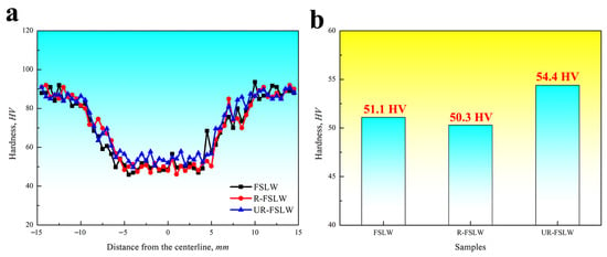
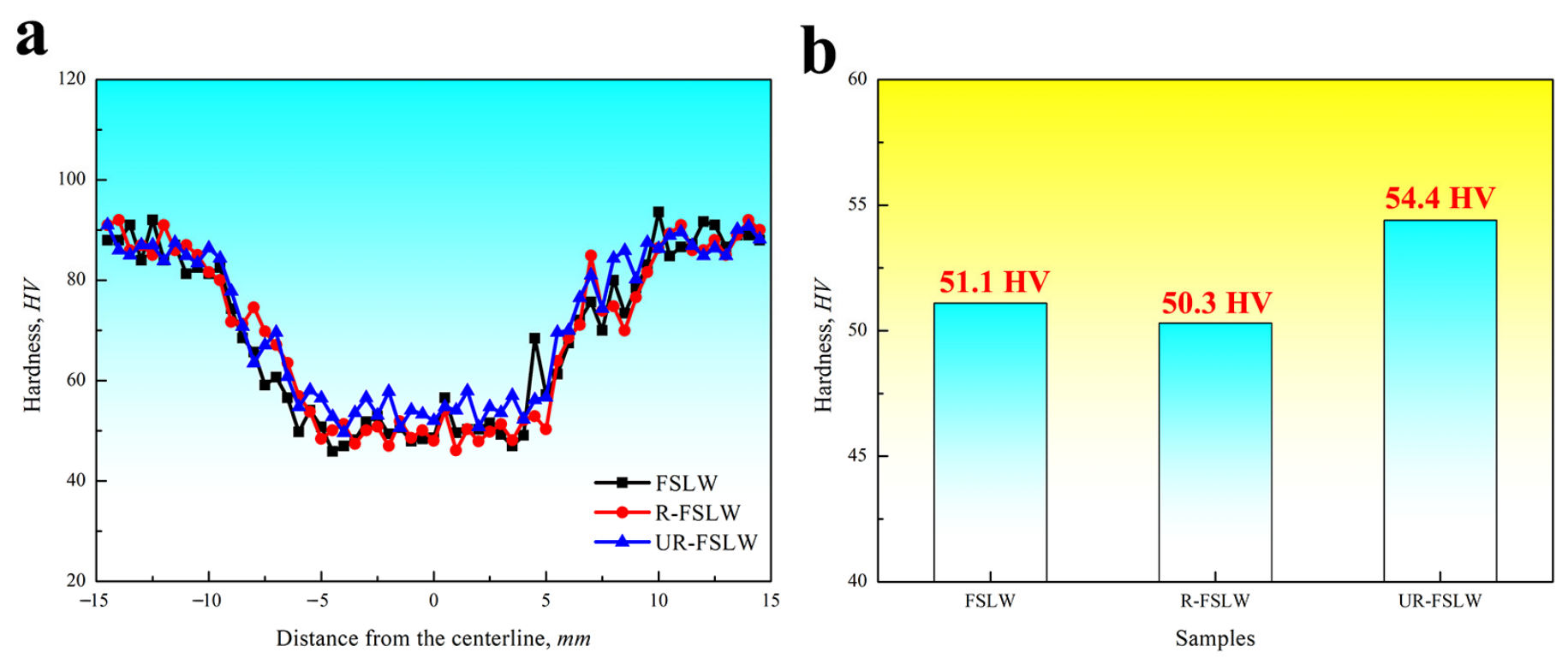
As shown in Figure 9a, the hardness distribution across the dissimilar Al/Mg joint displays a typical U-shaped profile, where NZ hardness drops to less than 55 HV after welding, compared with roughly 90 HV for the AA6061 base metal. Two main mechanisms account for this softening. Firstly, the Mg2Si precipitates, which serve as the key strengthening phase in AA6061, undergo dissolution or coarsening due to the welding heat input, directly reducing NZ hardness [41]. Secondly, DRX annihilates the dislocations, eliminating the dislocation strengthening effect. Although grain refinement also occurs in the NZ, the resulting grain-boundary strengthening is still insufficient to compensate for the loss of precipitation and dislocation strengthening. The conventional FSLW and R-FSLW joints exhibit similar hardness in the NZ, which is attributed to their comparable grain sizes. In contrast, the UR-FSLW joint benefits from finer grains, resulting in a higher NZ hardness (Figure 9b).
Figure 9.
(a) The hardness distributions and (b) the average hardness in the NZ of all dissimilar Al/Mg joints.
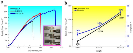
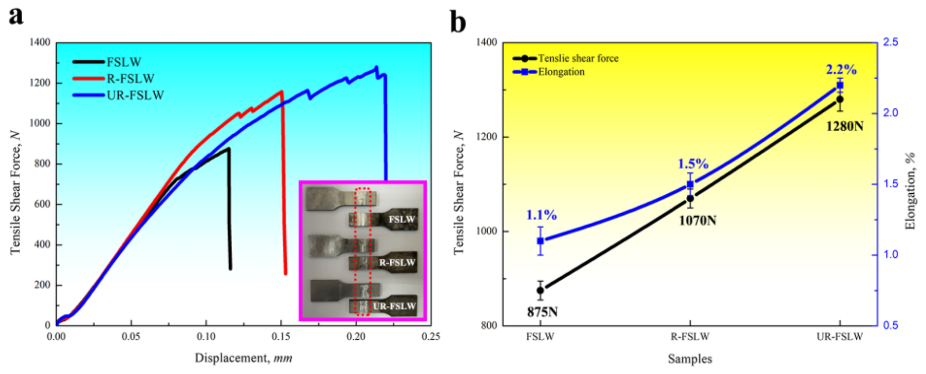
Figure 10 presents the tensile shear properties of all dissimilar Al/Mg joints. For the conventional FSLW joint, the tensile shear specimen fails within the NZ, exhibiting relatively poor mechanical performance. The tensile shear force reaches only about 875 N, and the joint ductility is also limited, with an elongation of just 1.1%. In contrast, the introduction of the AA6061 rivet significantly increases the tensile shear force of the R-FSLW joint, raising it from 875 N to 1070 N, and its elongation shows a slight improvement (from 1.1% to 1.5%). With the aid of ultrasonic assistance and self-riveting, the tensile shear force of the UR-FSLW joint was further enhanced to 1280 N, and its ductility was also improved, reaching twice that of conventional FSLW joints.
Figure 10.
(a) The tensile shear curves and images of failure specimens; (b) the tensile shear properties of all dissimilar Al/Mg joints.
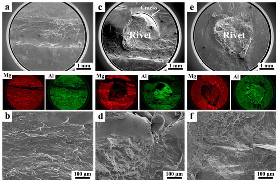
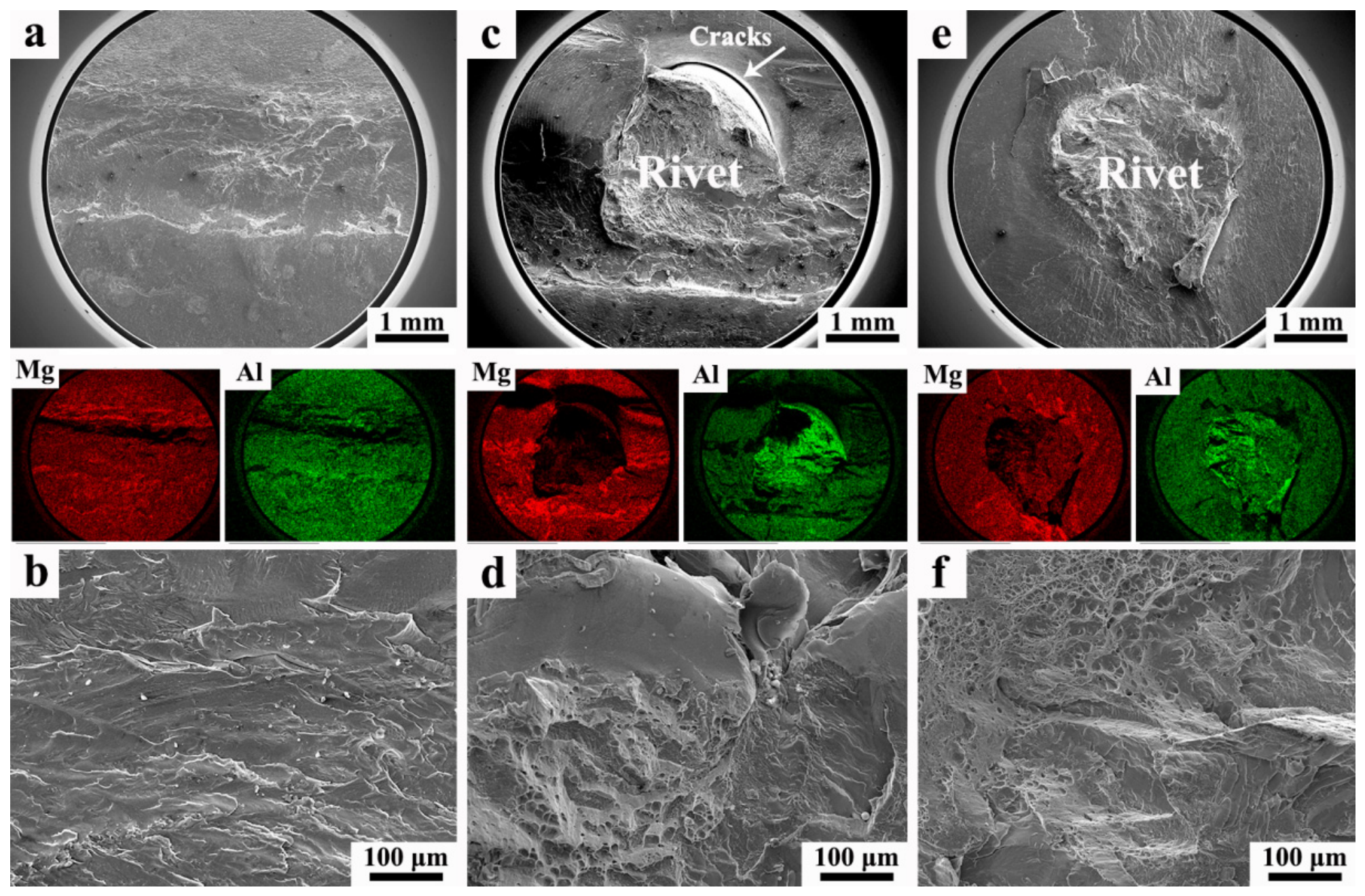
In order to analyze the fracture behavior, the failure morphologies of all dissimilar Al/Mg joints are detected, as shown in Figure 11. For the conventional FSLW joint, Al and Mg atoms are uniformly distributed on the fracture surface (Figure 11a), confirming that the fracture occurs through the IMC layer at the Al/Mg interface. In addition, the fracture surface exhibits a relatively flat morphology without dimples (Figure 11b), which is indicative of brittle fracture. The brittle and thick IMC layer in the FSLW joint facilitates crack initiation and growth, thereby deteriorating the mechanical properties [42]. For the R-FSLW joint, failure still takes place in the NZ (Figure 10a), and the AA6061 rivet is fractured, and its remnant remains lodged in the pre-drilled hole of AZ31 (Figure 11c). The IMC layer at the Al/Mg interface of the R-FSLW joint is measured to be approximately 15 μm, which is considerably thinner than that of a conventional FSLW joint (more than 20 μm), as shown in Figure 7 and Figure 8. This relatively thinner brittle IMC layer helps to alleviate local stress concentration at the interface, thereby delaying crack propagation during the tensile shear test and contributing positively to the elongation. Furthermore, the crack propagation paths of FSLW and R-FSLW joints were also different. During the tensile shear test, cracks in the conventional FSLW joint propagate rapidly along the thicker continuous IMC layer, resulting in a typical brittle fracture with limited elongation. For the R-FSLW joint, although the initial crack still initiates from the IMC layer around the Al rivet, the subsequent crack propagation path becomes more complex: the crack must traverse both the IMC layer and encounter the mechanical obstruction of the Al rivet, and the additional Al rivet increases the tensile shear force of the R-FSLW joint because of enhanced mechanical interlocking. However, distinct cracks are observed between the AA6061 rivet and the pre-drilled hole of AZ31, which form during welding because of the thick IMC layer in the R-FSLW joint (as shown in Figure 7d). The existence of such cracks partially diminishes the beneficial effect of self-riveting on the tensile shear performance, resulting in only a slight improvement in the elongation and ultimately leading to brittle fracture (Figure 11d). Why the rivet fractures rather than being pulled out of the hole is possibly attributable to the softening of AA6061 in the NZ. This softening reduces the deformation resistance of the AA6061 rivet, leading to its fracture during the tensile shear test. Similar to the R-FSLW joint, the UR-FSLW joint also fails in the NZ (Figure 10a), leaving a fractured AA6061 rivet inside the pre-drilled hole of AZ31 (Figure 11e). However, the bonding between the AA6061 rivet and the pre-drilled hole is relatively strong, and no crack is observed. Apart from that, the thickness of the brittle IMC layer in the UR-FSLW joint becomes thinner, which increases the ductility. Both flat morphology and dimples are observed on the fracture surface (Figure 11f), indicating a ductile-brittle failure mode. As a result, the transition from brittle to ductile-brittle fracture contributes to the increased elongation of the UR-FSLW joint. Due to grain refinement, softening of the NZ in the UR-FSLW joint is less pronounced than that in the R-FSLW joint, which enhances the deformation resistance of the AA6061 rivet and, consequently, further increases the tensile shear force.
Figure 11.
The fracture analysis and Al/Mg atom distribution of (a,b) FSLW joint; (c,d) R-FSLW joint; (e,f) UR-FSLW joint.
Further work: It can be seen that the combination of ultrasonic assistance and self-riveting effectively enhances the performance of dissimilar Al/Mg FSLW joints, whereas softening of the NZ accelerates rivet fracture, which may be detrimental to joint elongation (i.e., ductility). Therefore, further research is required to suppress softening of the NZ and shift the failure mode from rivet fracture to rivet pull-out.
Potential applications: The Al/Mg dissimilar joining addressed in this study (R-FSLW and UR-FSLW) has clear application potential in automotive and aerospace lightweight structures, as outlined below:
(1) Automotive body structures: Al/Mg hybrid structures are increasingly employed in body panels, door inner panels, seat frames, and battery pack housings. The R-FSLW method proposed in this work provides additional mechanical interlocking via the Al rivet, ensuring reliable joint performance even in the presence of brittle IMC layers. This feature is particularly attractive for structural joints requiring crashworthiness and long-term reliability.
(2) Aerospace applications: In non-primary load-bearing components such as aircraft cabin doors, interior frames, and satellite brackets, Al/Mg hybrid designs offer further weight reduction. The ultrasonic-assisted FSW enables sound joining at lower heat input, which helps control welding distortion in thin-walled aerospace structures, a critical factor for precision assembly.
4. Conclusions
The weld performance of dissimilar Al/Mg joints fabricated via conventional FSLW, R-FSLW and UR-FSLW was investigated, and the following results were summarized:
(1) Compared with the conventional FSLW joint, the self-riveting design introduced an AA6061 rivet in the R-FSLW joint, enhancing the mechanical interlocking between Al and Mg. Meanwhile, AZ31 fragments were stirred into the NZ, forming Al-Mg IMCs. For the UR-FSLW joint, the acoustoplastic effect induced by ultrasonic assistance further improved material flow during welding, reducing the unfilled area of the AA6061 rivet from 0.83 mm2 to 0.61 mm2. Furthermore, the mixing between Al and Mg was also intensified, resulting in lamellar structures in the NZ.
(2) For the conventional FSLW joint, the grains and second-phase particles were refined, and a continuous and distinct IMC layer formed at the Al/Mg interface, with a thickness of more than 20 μm. The microstructural evolution in the NZ of the R-FSLW joint was similar to that of the conventional FSLW joint due to the comparable welding parameters; however, cracks formed along the IMC layer between the AA6061 rivet and the pre-drilled AZ31 hole. In contrast, ultrasonic assistance further refined the grains and IMC layers, inhibiting crack formation.
(3) The conventional FSLW joint failed in a brittle manner during the tensile shear test, exhibiting a tensile shear force of only 875 N and an elongation of just 1.1%. By comparison, introduction of the AA6061 rivet enhanced the performance of the U-FSLW joint, increasing the tensile shear force to 1070N; however, the presence of cracks and a relatively thick IMC layer resulted in only a slight improvement in elongation (from 1.1% to 1.5%) and ultimately led to brittle fracture. The combination of ultrasonic assistance and self-riveting showed a positive effect on the mechanical properties of the UR-FSLW joint, further increasing the tensile shear force (from 1070 N to 1280 N) and elongation (from 1.5% to 2.2%) through the AA6061 rivets and refined microstructures, and shifting the fracture mode from brittle to ductile-brittle.
Author Contributions
Conceptualization, Y.C.; methodology, Y.Z., S.W. and X.L.; investigation, Y.Z., S.W. and X.L.; resources, Y.C. and H.Y.; writing—original draft preparation, Y.Z., S.W. and X.L.; writing—review and editing, Y.C. and H.Y.; supervision, Y.C.; project administration, Y.C. and H.Y.; funding acquisition, Y.C. All authors have read and agreed to the published version of the manuscript.
Funding
This research was funded by the Guangdong Basic and Applied Basic Research Foundation (grant number 2025A1515012322) and the Open Research Fund of the State Key Laboratory of Precision Manufacturing for Extreme Service Performance (grant number Kfkt2024–03).
Data Availability Statement
The original contributions presented in this study are included in the article. Further inquiries can be directed to the corresponding author.
Conflicts of Interest
The authors declare no conflicts of interest.
References
- Singh, V.P.; Patel, S.K.; Ranjan, A.; Kuriachen, B. Recent research progress in solid state friction-stir welding of aluminum-magnesium alloys: A critical review. J. Mater. Res. Technol. 2020, 9, 6217–6256. [Google Scholar] [CrossRef] [Scilit]
- Zhang, G.L.; Gao, J.Q.; Wu, C.S. Dislocation density based constitutive model for ultrasonic vibration assisted friction stir welding of dissimilar Al/Mg alloys. J. Manuf. Process. 2024, 131, 336–355. [Google Scholar] [CrossRef] [Scilit]
- Ji, S.D.; Li, Z.W.; Zhang, L.G.; Zhou, Z.L.; Chai, P. Effect of lap configuration on magnesium to aluminum friction stir lap welding assisted by external stationary shoulder. Mater. Des. 2016, 103, 160–170. [Google Scholar] [CrossRef] [Scilit]
- Yang, F.H.; Zhao, J.J.; Zhao, B.; Zhang, J.H.; Han, L.Y.; Ma, H.L. Effect of metallic interlayer and ultrasonic vibration on intermetallic compounds in friction stir lap welding of dissimilar Al/Mg alloys. Mater. Charact. 2026, 238, 116573. [Google Scholar] [CrossRef] [Scilit]
- Abdollahzadeh, A.; Shokuhfar, A.; Cabrera, J.M.; Zhilyaev, A.P.; Omidvar, H. The effect of changing chemical composition on dissimilar Mg/Al friction stir welded butt joints using zinc interlayer. J. Manuf. Process. 2018, 34, 18–30. [Google Scholar] [CrossRef] [Scilit]
- Karimi-Dermani, O.; Abbasi, A.; Roeen, G.A.; Nayyeri, M.J. Dissimilar friction stir lap welding of AA7075 to AZ31B in the presence of Sn interlayer. J. Manuf. Process. 2021, 68, 616–631. [Google Scholar] [CrossRef] [Scilit]
- Huang, Y.Y.; Xie, Y.M.; Meng, X.C.; Lv, Z.L.; Cao, J. Numerical design of high depth-to-width ratio friction stir welding. J. Mater. Process. Technol. 2017, 252, 233–241. [Google Scholar] [CrossRef] [Scilit]
- Boccarusso, L.; Astarita, A.; Carlone, P.; Scherillo, F.; Rubino, F.; Squillace, A. Dissimilar friction stir lap welding of AA6082-Mg AZ31: Force analysis and microstructure evolution. J. Manuf. Process. 2019, 44, 376–388. [Google Scholar] [CrossRef] [Scilit]
- Peng, P.; Wang, W.; Jin, Y.Y.; Liu, Q.; Zhang, T.; Qiao, K.; Cai, J.; Wang, K.S. Experimental investigation on fatigue crack initiation and propagation mechanism of friction stir lap welded dissimilar joints of magnesium and aluminum alloys. Mater. Charact. 2021, 177, 111176. [Google Scholar] [CrossRef] [Scilit]
- Subramanian, S.; Natarajan, E.; Khalfallah, A.; Muthukutti, G.P.; Beygi, R.; Louhichi, B.; Sengottuvel, R.; Ang, C.K. Current trends and emerging strategies in friction stir spot welding for lightweight structures: Innovations in tool design, robotics, and composite reinforcement-A review. Crystals 2025, 15, 556. [Google Scholar] [CrossRef] [Scilit]
- Zhai, M.; Yin, J.L.; Yang, C.L.; Wu, C.S.; Song, H.T.; Zhao, W.Z.; Shi, L.; Qiao, J.N. Investigating the relationship of process parameter, heat-mass transfer and joint strength in Mg/Al friction stir lap welding via experiments, machine learning and numerical analysis. Int. J. Heat Mass Transf. 2025, 247, 127143. [Google Scholar] [CrossRef] [Scilit]
- Tan, S.; Zheng, F.Y.; Chen, J.; Han, J.Y.; Wu, Y.J.; Peng, L.M. Effects of process parameters on microstructure and mechanical properties of friction stir lap linear welded 6061 aluminum alloy to NZ30K magnesium alloy. J. Magnes. Alloys 2017, 5, 56–63. [Google Scholar] [CrossRef] [Scilit]
- Zhao, Y.; Jiang, S.; Yang, S.F.; Lu, Z.P.; Yan, K.M. Influence of cooling conditions on joint properties and microstructures of aluminum and magnesium dissimilar alloys by friction stir welding. Int. J. Adv. Manuf. Technol. 2016, 83, 673–679. [Google Scholar] [CrossRef] [Scilit]
- He, C.S.; Wang, T.; Zhang, Z.Q.; Qiu, C.P. Coupling effect of axial ultrasonic vibration and tool thread on the microstructure and properties of the friction stir lap welding joint of Al/Mg dissimilar alloys. J. Manuf. Process. 2022, 80, 95–107. [Google Scholar] [CrossRef] [Scilit]
- Yin, Q.P.; Gao, S.; Shi, L.; Jing, Y.K.; Kuamr, S.; Wang, S.L.; Zhao, W. Synergistic effects of ultrasonic vibration and sled-riveting on the microstructure and mechanical properties of aluminum/steel friction stir lap welded joints. J. Mater. Res. Technol. 2025, 39, 1442–1455. [Google Scholar] [CrossRef] [Scilit]
- Yi, T.; Liu, S.; Fang, C.; Jiang, G. Eliminating hole defects and improving microstructure and mechanical properties of friction stir welded joint of 2519 aluminum alloy via TIG arc. J. Mater. Process. Technol. 2022, 310, 117773. [Google Scholar] [CrossRef] [Scilit]
- Liu, J.; Wu, B.; Wang, Z.; Li, C.; Chen, G.; Miao, Y. Microstructure and mechanical properties of aluminum-steel dissimilar metal welded using arc and friction stir hybrid welding. Mater. Des. 2023, 225, 111520. [Google Scholar] [CrossRef] [Scilit]
- Chen, Y.; Tan, J.; Liu, R.C.; Li, J.Z.; Li, W.Y. Coupling effect of ultrasonic assistance and Zn interlayer on the performance of dissimilar Al/Mg friction stir lap welds. J. Mater. Eng. Perform. 2026, 35, 16678–16690. [Google Scholar] [CrossRef] [Scilit]
- Chen, Z.W.; Shi, L.; Su, H.; Wu, C.S. Numerical and experimental investigation on intermetallic compounds formation in ultrasonic vibration enhanced friction stir welding of dissimilar Al/Mg alloys. J. Alloys Compd. 2024, 977, 173426. [Google Scholar] [CrossRef] [Scilit]
- He, F.; Wu, C.; Shi, L. Influence of ultrasonic vibration on the grain structure and dislocation density in friction stir welding of dissimilar Al/Mg alloys. Mater. Today Commun. 2024, 40, 110065. [Google Scholar] [CrossRef] [Scilit]
- Chen, Y.; Liu, R.C.; Tan, J.; He, Q.W. Ultrasonic-assisted dissimilar friction stir lap welding of AA2024 and AZ31: A comparative study of cold and hot welding parameters. Metals 2025, 15, 1191. [Google Scholar] [CrossRef] [Scilit]
- Huang, Y.X.; Wang, J.C.; Wan, L.; Meng, X.C.; Liu, H.B.; Li, H. Self-riveting friction stir lap welding of aluminum alloy to steel. Mater. Lett. 2016, 185, 181–184. [Google Scholar] [CrossRef] [Scilit]
- Huang, Y.X.; Huang, T.F.; Wan, L.; Meng, X.C.; Zhou, L. Material flow and mechanical properties of aluminum-to-steel self-riveting friction stir lap joints. J. Mater. Process. Technol. 2019, 263, 129–137. [Google Scholar] [CrossRef] [Scilit]
- Chen, Y.; Cai, Z.H.; Ding, H.; Zhang, F.H. Characteristics of dissimilar aluminum/steel joint fabricated via self-riveting friction stir lap welding. Trans. Indian Inst. Met. 2021, 74, 2621–2629. [Google Scholar] [CrossRef] [Scilit]
- Shi, L.; Wu, C.S.; He, F.L.; Dai, G.X.; Kumar, A. Unveiling the mechanism of ultrasonic vibration on suppression of intermetallic compound growth in Al/Mg dissimilar friction stir welding. J. Magnes. Alloys 2026, 18, 10181. [Google Scholar] [CrossRef] [Scilit]
- Chen, Y.; Liu, R.C.; Tan, J.; Li, J.Z. Effect of ultrasonic power on the performance of dissimilar Al alloy friction stir lap weld. Metals 2025, 15, 1017. [Google Scholar] [CrossRef] [Scilit]
- Wu, Y.D.; Wang, H.F.; Ban, C.Y. Effect of Fe content on the microstructure and properties of hot-extruded 6061 aluminum alloy. In Proceedings of the 7th International Conference on Mechanical Engineering, Materials and Automation Technology, Dali, China, 18–20 June 2021. [Google Scholar]
- Manjhi, S.L.; Sekar, P.; Bontha, S.; Balan, A.S.S. Effect of equiaxed grains and secondary phase particles on mechanical properties and corrosion behavior of CMT-based wire arc additive manufactured AZ31 alloy. CIRP J. Manuf. Sci. Technol. 2024, 46, 48–64. [Google Scholar] [CrossRef] [Scilit]
- Liu, H.J.; Hu, Y.Y.; Du, S.S.; Zhao, H.H. Microstructure characterization and mechanism of acoustoplastic effect in friction stir welding assisted by ultrasonic vibrations on the bottom surface of work pieces. J. Manuf. Process. 2019, 42, 159–166. [Google Scholar] [CrossRef] [Scilit]
- Zhang, Z.Q.; He, C.S.; Li, Y.; Yu, L.; Zhao, S.; Zhao, X. Effects of ultrasonic assisted friction stir welding on flow behavior, microstructure and mechanical properties of 7N01-T4 aluminum alloy joints. J. Mater. Sci. Technol. 2020, 43, 1–13. [Google Scholar] [CrossRef] [Scilit]
- Li, W.Y.; Li, J.F.; Zhang, Z.H.; Gao, D.L.; Chao, Y.J. Metal flow during friction stir welding of 7075-T651 aluminum alloy. Exp. Mech. 2013, 53, 1573–1582. [Google Scholar] [CrossRef] [Scilit]
- Su, J.Q.; Nelson, T.W.; Sterling, C.J. Microstructure evolution during FSW/FSP of high strength aluminum alloys. Mater. Sci. Eng. A 2005, 405, 277–286. [Google Scholar] [CrossRef] [Scilit]
- Azimzadegan, T.; Serajzadeh, S. An investigation into microstructures and mechanical properties of AA7075-T6 during friction stir welding ta relatively high rotational speeds. J. Mater. Eng. Perform. 2010, 19, 1256–1263. [Google Scholar] [CrossRef] [Scilit]
- Ji, G.L.; Li, F.G.; Li, Q.H.; Li, Q.H.; Li, H.Q.; Li, Z. Research on the dynamic recrystallization kinetics of Aermet100 steel. Mater. Sci. Eng. A 2010, 527, 2350–2355. [Google Scholar] [CrossRef] [Scilit]
- Hu, Y.Y.; Liu, H.J.; Fujii, H.; Ushioda, K. Effect of ultrasound on microstructure evolution of friction stir welded aluminum alloys. J. Manuf. Process. 2020, 56, 362–371. [Google Scholar] [CrossRef] [Scilit]
- Chen, Y.; Ding, H.; Li, J.Z.; Cai, Z.H.; Zhao, J.W.; Yang, W.J. Influence of multi-pass friction stir processing on the microstructure and mechanical properties of Al-5083 alloy. Mater. Sci. Eng. A 2016, 650, 281–289. [Google Scholar] [CrossRef] [Scilit]
- Yang, Y.; Shen, Z.; Zhou, P.; Guo, S.; Guo, Y.; Hou, W.; Piao, Z.; Yan, S.; Liang, D.; Li, H. Interfacial microstructure and mechanical performance of oscillating refill friction stir spot welded AL/Mg dissimilar welds. J. Manuf. Process. 2026, 158, 251–274. [Google Scholar] [CrossRef] [Scilit]
- Zhao, J.J.; Wu, C.S.; Su, H. Ultrasonic effect on thickness variations of intermetallic compound layers in friction stir welding of aluminum/magnesium alloys. J. Manuf. Process. 2021, 62, 388–402. [Google Scholar] [CrossRef] [Scilit]
- Fu, X.S.; Chen, K.; Zhang, Q.S.; Chen, N.N.; Wang, M.; Hua, X.M. Interfacial intermetallic compounds layer in friction stir welded Mg/Al joints: Relationship between thickness and the welding temperature history. J. Magnes. Alloys 2025, 13, 2540–2553. [Google Scholar] [CrossRef] [Scilit]
- Liu, T.; Gao, S.; Shen, X.Y.; Sun, Z.P.; Shi, L.; Kumar, S.; Yang, C.L. Acoustic effect on the joint quality and process of friction stir lap welding of aluminum to steel. Mater. Today Commun. 2023, 35, 106184. [Google Scholar] [CrossRef] [Scilit]
- Liu, X.C.; Wang, Q.; Pei, X.J.; Li, Y.Z.; Zhen, Y.Q.; Shen, Z.K.; Chen, H.Y. Microstructural evolution of 6061-T6 aluminum alloy in vortex-friction stir welding. Mater. Charact. 2023, 195, 112544. [Google Scholar] [CrossRef] [Scilit]
- Kumar, S.; Wu, C.S. Suppression of intermetallic reaction layer by ultrasonic assistance during friction stir welding of Al and Mg based alloys. J. Alloys Compd. 2020, 827, 154343. [Google Scholar] [CrossRef] [Scilit]

Disclaimer/Publisher’s Note: The statements, opinions and data contained in all publications are solely those of the individual author(s) and contributor(s) and not of MDPI and/or the editor(s). MDPI and/or the editor(s) disclaim responsibility for any injury to people or property resulting from any ideas, methods, instructions or products referred to in the content. |
© 2026 by the authors. Licensee MDPI, Basel, Switzerland. This article is an open access article distributed under the terms and conditions of the Creative Commons Attribution (CC BY) license.