


Abstract
Engineering components often require different properties in different regions, and a single material may not provide all of them. Reliable joining is important for refractory metal–steel, dissimilar superalloy, and Ti/Mg combinations. Field-assisted sintering technology/spark plasma sintering (FAST/SPS) combines pressure with rapid heating for direct joining and fabrication of interlayered and graded metallic structures in short cycles. This review evaluates factors affecting bond formation and mechanical integrity at FAST/SPS-processed metallic interfaces. Sufficient real contact is needed for load transfer but does not alone ensure mechanical integrity. Surface oxides can restrict contact, while local deformation may increase contact area and disrupt oxide films. As contact develops, atomic transport and interfacial reactions may alter transition-region composition and phase morphology, affecting fracture paths. Interlayers may improve contact and limit undesirable reactions but can also create new interfaces and reaction regions. Compositional transitions, reaction regions, and local hardness indicate interface development, but assessing their mechanical significance requires mechanical testing and fracture analysis. Room-temperature performance alone does not define service behavior. Thermal cycling, high heat flux, electrical conditions, or corrosive environments may therefore require application-specific evaluation. Differences in materials, equipment, geometry, and test methods limit direct comparison. Processing windows should therefore be tailored to each material pair and interface architecture according to operating temperature, loading, functional requirements, and environmental exposure.
1. Introduction
Engineering components may require high-temperature resistance in one region and ductility in another, or high conductivity in one region and mechanical strength in another. A single material may not satisfy these distinct regional requirements simultaneously. Multi-material design uses different materials in regions where their properties are most useful [1,2]. Applications include multi-alloy titanium- and nickel-based components produced by field-assisted sintering technology (FAST)-based routes [1,2] and power-electronics interconnects [3]. The sintered W/F82H blanket interface produced by spark plasma sintering (SPS) [4] and hybrid multimaterial architectures produced by combining additive manufacturing and SPS [5] are further examples of this approach. However, the success of this approach depends not only on the properties of the selected materials but also on the structure and integrity of the region formed between them.
Joining dissimilar metallic materials by FAST/SPS requires consideration of differences in deformation behavior, thermal expansion, atomic transport, interfacial reaction behavior, and oxide stability. In Ti/Mg joints and Nb-Si/TiAl interfaces, interfacial diffusion and phase formation have markedly altered bonding strength and fracture behavior [6,7]. This situation requires the interface to be treated not merely as a thin geometric boundary but as a finite transition region in which composition and microstructure are designed together.
In this review, the terms FAST and SPS are collectively denoted as FAST/SPS, in line with common usage in the literature [8]. The method combines rapid heating with uniaxial pressure, allowing densification and joining to proceed within the same cycle. Powder–solid and powder–powder joints, as well as interlayered and graded architectures, can be produced using this method. Powder–solid Ni-based superalloy joints for turbine-disk applications [8] and functionally graded stainless-steel structures [9] illustrate the diversity of applications. Despite this diversity, high relative density alone should not be taken as evidence of mechanical and interfacial reliability [9].
Bond formation begins with the establishment of sufficient, continuous metallic contact at the interface [10]. As surface asperities deform locally [10], particles rearrange and pores close in powder-containing regions [9]. In some metal pairs, surface nanocrystallization and low roughness promoted bonding at low temperature [10,11]. Pre-deformation increased dislocation density and promoted interfacial diffusion [12], whereas in Cu/Cu joints, metallic silver produced by the decomposition of silver oxalate (Ag2C2O4) during processing formed an in situ brazing layer between the surfaces [13]. These examples show that, in addition to surface topography, surface nanostructure, pre-deformation, and metallic interlayers formed in situ during processing may also influence bond formation. Macroscopic appearance alone cannot determine the state of surface oxide films. Direct interfacial characterization is needed to assess whether they remain continuous, are disrupted, or persist as residues.
Following contact, elemental distribution, phase formation, and grain structure alter interface behavior. An elemental gradient, the formation of new phases, grain-boundary migration, and disappearance of the initial interface do not describe the same structural state. In some aluminum-alloy joints, discontinuous reaction products have been associated with more favorable fracture behavior [14]. In TiAl-based joints with interlayers, continued evolution of the reaction zones was associated with a decrease in shear strength beyond the optimum bonding condition [15]. In Nb-Si/TiAl joints, elemental interdiffusion between the mating materials governed reaction evolution [7], and observations in transient liquid phase joints indicated that boride morphology could alter the crack path [16]. The mechanical effect of a reaction zone depends on the identity, continuity, and morphology of the phase and its position along the fracture path.
Interlayers and graded architectures are used to improve interfacial contact and promote interfacial diffusion [17], limit detrimental interfacial reactions, or reduce property mismatches between adjacent layers [18]. A Cu interlayer was associated with defect-free interfaces in 93W–Mo1 joints and with higher measured shear strength [17]. The microstructural response of a multilayer W–steel structure during annealing varied among its compositionally distinct interfaces [18]. However, added layers also create new interfaces at which voids may develop and along which fracture may propagate [19,20], while interfacial reactions may also occur [20].
Mechanical measurements used in studies of interface performance are not necessarily directly comparable. Tensile, shear, and bending tests, loads measured with custom fixtures, hardness, and local indentation represent different physical responses. For example, room-temperature shear failure in the titanium–zirconium–molybdenum (TZM) alloy/tungsten–rhenium (WRe) alloy joint bonded at 1600 °C occurred in the TZM substrate rather than at the interface [21]. Thus, the interface was not the failure location in that test, but the test did not determine the interfacial strength. Room-temperature mechanical results do not by themselves characterize behavior under repeated or transient thermal-shock loading [21,22]. In refractory-metal joints, repeated thermal-shock exposure was followed by lower measured shear strength [21], whereas transient laser thermal-shock tests showed interfacial damage that varied with sintering temperature [22]. In coating–superalloy systems, hot-corrosion behavior has been evaluated separately from pull-off bonding strength [23].
When interpreting FAST/SPS results, it is difficult to distinguish current-induced thermal effects from possible non-thermal electrical effects. Pulsed current supplies electric resistance energy directly to the specimen [24] and can generate Joule heating at contact regions [25]. However, the reported equipment maximum current does not quantify the current actually passing through the specimen or the local current density at the interface [24]. The current passing through the specimen or interface was not reported in either study [24,25]. In addition, [25] included a hot-pressing comparison at the same nominal bonding temperature, pressure, and holding time, but with a different heating configuration and temperature field. Thus, these experiments do not independently quantify any non-thermal electrical contribution to bonding [24,25]. A low processing temperature selected using thermodynamic calculations does not, by itself, confirm a non-thermal electrical mechanism [26]. The level of methodological detail varies across studies, particularly for surface preparation, temperature-measurement location, current path, interlayer geometry, characterization resolution, and mechanical test setup. The studies reviewed here have generally focused on a single material pair or architecture. Within these studies, the formation of real contact, reaction evolution, fracture path, and service behavior have not typically been evaluated together within the same study. Because these differences make it difficult to define a universal temperature–pressure–time processing window, this review compares the conditions that jointly influence contact, chemistry, and integrity.
This review presents a comparative analysis of the development of real contact at metal–metal interfaces produced by FAST/SPS and the role of chemical and architectural design in defect formation and fracture paths. The relationship between microstructural findings and service behavior is also evaluated. The aim is not to propose universal processing parameters but to establish an assessment approach for evaluating acceptable conditions for contact, chemistry, architecture, and mechanical integrity for each material system and service objective.
2. Literature Search and Evaluation
The literature search was conducted in the Web of Science Core Collection and Scopus databases. The terms FAST, SPS, field-assisted sintering, spark plasma sintering, pulsed electric current, and plasma-activated sintering were searched in combination with concepts related to bonding, interlayers, multilayer structures, and graded metallic architectures. A total of 174 records were retrieved from Web of Science and 202 from Scopus. Of the 376 records, 166 duplicates were removed, and the remaining 210 publications were screened at the title and abstract level. At this stage, 103 publications were excluded. Of the 107 publications whose full texts were assessed, 85 were included in the review. The reporting of the study selection process was guided in part by the Preferred Reporting Items for Systematic Reviews and Meta-Analyses (PRISMA) 2020 guidelines [27]. The literature selection process is shown in Figure 1.
Figure 1.
Literature search and study selection process.
English-language articles reporting original experimental results on engineered metal–metal interfaces formed using FAST/SPS or a directly related method combining pulsed current and pressure were included in the review. Solid–solid, powder–solid, and powder–powder joints, as well as interlayered, multilayer, and functionally graded structures, were retained within the scope. Publications were excluded if they fell outside the scope, if their interfaces were not produced by FAST/SPS, if they did not report original experimental results, if their full texts were inaccessible, or if they were not written in English.
The included studies were examined in terms of material system, interface design, processing conditions, and the results obtained. Because the materials, specimen geometries, and test methods differed substantially, the results were not combined quantitatively. Instead, common trends and differences among systems were compared.
3. Bond Formation and the Development of Real Contact in FAST/SPS
3.1. Real Contact and Processing Variables
Bonding in FAST/SPS does not occur merely because the surfaces are brought into contact. Initial load transfer begins in the limited regions where surface asperities meet, and stress concentrates at these points. As temperature increases, flow stress generally decreases, asperity peaks deform more readily, and the real contact area expands. As gaps shrink, regions form in which metallic bonding can develop.
Figure 2a shows the FAST/SPS setup. While uniaxial pressure promotes contact and densification, pulsed direct current can cause Joule heating along electrically conductive paths in the tooling and specimen. Current and heat paths are shown schematically. The actual current and heat distributions can depend on die geometry, the electrical conductivity of the specimen, and contact resistances. SPS is used to consolidate both metallic and ceramic powders [9]. Ceramic powders commonly include oxide, nitride, and carbide compositions. Because this review focuses on multi-material metallic systems, the powder-containing architectures considered here are metal powder–metal powder and metal powder–solid metal configurations, shown in Figure 2b and Figure 2c, respectively. Figure 2d–f shows the solid–solid, interlayered, and functionally graded architectures. These architectures differ in their initial contact configuration and densification requirements.
Figure 2.
Field-assisted sintering technology (FAST)/spark plasma sintering (SPS) setup and main multi-material interface architectures.
The path by which real contact develops may vary with interface architecture. In Ni-nanocoated GH536 joints, unbonded zones and interfacial voids decreased as bonding temperature or time increased, while plastic deformation of the coating was proposed as an early-stage contact mechanism [10]. Bonding in powder-metallurgy high-speed steel was described as progressing from point contacts and gaps to a grain boundary containing residual pores, followed by pore elimination through grain-boundary diffusion [25]. In powder interlayers made from the Fe-based oxide dispersion-strengthened (ODS) superalloy MA956 and the Ni-based ODS superalloy MA754, plastic flow was followed by closure of the remaining pores through volume diffusion [28].
Figure 3a shows the initial surfaces. Figure 3b–e show initial contact islands, local plastic deformation, local oxide disruption and metallic contact, and a developed interface, respectively. Initial contact occurs as discrete islands at asperity peaks. As local plastic deformation increases the contact area, metallic contact and atomic transport may begin in regions where surface films are disrupted. Within an appropriate processing window, a more continuous bond line with fewer gaps may develop, together with a transition region in some systems. Insufficient processing may leave areas of incomplete contact and pores. By contrast, excessive processing may produce thick reaction regions, new voids, or microstructural degradation. Disruption of the oxide film, grain continuity, and development of the transition region vary with the material system.
Figure 3.
Development of real contact during FAST/SPS and possible interface states depending on the processing window.
Pressure increases the real contact area, while temperature and time promote metallic bonding and atomic transport. At low temperature, the surfaces may deform, but metallic contact and transport can remain limited. An excessive increase in temperature or an extended holding time, however, may lead to deformation, grain growth, or undesirable reactions. In Cu/Cu joints, high-strength bonds were obtained at low temperature using controlled surface preparation and selected combinations of temperature, time, and pressure [11,29]. In direct 75W/bulk-W joints, bonding at 1200 °C produced metallurgical bonding over most of the interface, but excessive thickness reduction and unbonded or delaminated edge regions remained [30]. In 316L joints with a powder interlayer, pressure increased densification, whereas excessive pressure caused pronounced macroscopic deformation [31]. In a similar-material joint of extruded Ti-22Al-25Nb alloy, temperature and time likewise altered both the interface microstructure and the mechanical response [32]. The appropriate processing window depends on the balance between bond formation and dimensional and microstructural stability.
3.2. Architecture-Dependent Contact and Deformation
In solid–solid joints, surface topography influences the real contact area, while surface films influence whether that contact becomes metallic. Smooth surfaces facilitate contact, whereas larger surface irregularities can hinder the closure of local gaps. When a continuous stable oxide film persists, geometric conformity alone may not ensure metallic bonding. Cu/Cu surfaces machined by single-point diamond turning revealed the combined influence of topography and surface nanostructure [11]. In studies of Alloy 617, interface continuity and grain-boundary migration were examined together with processing conditions [33,34].
Soft metallic interlayers can accommodate surface asperities and facilitate initial contact. In 5A06 aluminum-alloy joints, the soft 1060 Al layer increased plastic accommodation and facilitated disruption of the oxide film [14]. In the CuNi/Ag/CuNi sandwich interlayer used in an Mg/Al joint, the Ag foil conformed to the rough CuNi surfaces during bonding and improved contact [35].
In powder–solid and powder–powder systems, densification and interface bonding can develop during the same consolidation cycle. Particle deformation contributes to early densification, while volume diffusion controls the final stage [28]. In 316L joints with a powder interlayer, increasing pressure reduced the layer thickness and porosity [31]. If the powder interlayer does not densify sufficiently, a porous region may remain. Bulk relative density alone does not establish interface continuity, so bulk densification and local interface continuity should be considered separately. Ryshkewitch reported a decrease in compressive strength with increasing porosity [36], and Duckworth expressed this strength–porosity dependence in exponential form [37]. The Ryshkewitch–Duckworth equation has also been discussed among well-known porosity–property models in a study of porous NiTi [38]. Such bulk porosity–property relations do not by themselves establish local interface continuity. In ODS Eurofer steel joined with a powder interlayer, increasing the powder amount reduced cavities and crack length, while longer holding eliminated most of the remaining cavities. At the longest holding time, an almost defect-free joint was obtained [39]. In a FAST preform containing different Ti-alloy powder regions, the bond region was evaluated together with subsequent deformation behavior [40].
Nominal pressure and total axial displacement do not directly reveal the contact condition at every point along the interface. Geometric and material nonuniformities can lead to local differences in contact and deformation. Differences in bonding between the edge regions and the rest of the interface were evident in W-based joints [30]. Axial displacement can also reflect deformation of the bulk specimen or interlayer rather than interface closure alone. Insufficient deformation may leave parts of the interface in incomplete contact, whereas excessive deformation may be accompanied by substantial layer thinning and edge separation. Likewise, a local microstructural image or an overall density value cannot capture edge gaps, local chemistry, and fracture location throughout the joint.
In PWA1429–PWA1429 superalloy joints, a heterogeneous precipitate structure and brittle interfacial behavior were observed, while the joined interphase was reported to be void-free [41]. The authors suggested that non-flat joining surfaces could produce spatial variations in current density, temperature, and diffusion rate that could contribute to the precipitate heterogeneity, but the study did not report experiments separating these coupled contributions [41].
3.3. Interpretation of Current Effects
In FAST/SPS, electric current changes heat generation in the die, punches, specimen, and contact regions [10,34]. Local current concentration and associated Joule heating at contact points may accelerate bonding [10]. However, the total die-assembly current does not indicate the actual current passing through the specimen or the local current density at the interface [34]. Without measurements of the microscale local temperature field and local current distribution, the thermal effect cannot be separated quantitatively from possible athermal contributions [10,34]. In Ni-nanocoated GH536 joints, rapid interfacial void closure was documented in detail, but the respective contributions of local heating and possible current-assisted deformation effects were not quantified separately [10]. In the Alloy 617 study, hot pressing was used as a current-free comparison [34]. Because the heating and cooling rates differed between electric field-assisted sintering and hot pressing, the available data do not provide a quantitative isolation of the current-specific contribution [34].
4. Surface Preparation and Oxide Management
4.1. Initial Surface Condition and Mechanical Preparation
The surface condition before joining cannot be described by roughness alone [11,14,42]. Surface oxide films [14,42] and near-surface deformation [11] can also influence bonding. Smoother surfaces may increase the bonding ratio, whereas rougher surfaces may leave unbonded regions [11]. Sufficient local deformation can disrupt the oxide film [14,42]. However, when an oxide film persists during processing, intimate contact alone does not ensure sound metallurgical bonding [14,42]. Topographic features should not be interpreted independently of surface chemistry [11,14,42].
In Alloy 617 joints, the surfaces were mechanically polished using 400-, 600-, and 800-grit SiC papers, and roughness was reported quantitatively [33]. No separate chemical oxide-removal treatment was reported, and the roughness data alone do not directly describe the state of the oxide film. In PM2000 joints, lapped surfaces were compared at different temperatures [43]. In the PM2000 test series, surface preparation, temperature, and holding time varied across the experiments, so the effect of roughness was not isolated quantitatively. Bond failure during machining also reduced the number of tensile specimens available for mechanical testing [43].
Plastic deformation may increase the dislocation density in the near-surface region or form a fine-grained layer [11]. In the Cu/Cu system, single-point diamond turning produced a surface with very low roughness and a nanocrystalline layer approximately 230 nm thick. When these surfaces were joined by SPS at 202 °C, a tensile strength of approximately 269 MPa was obtained, and recrystallized micrometer-sized grains were observed to span the bonding interface. This value corresponds to approximately 96% of the tensile strength of the as-received Cu, which was about 280 MPa. No effective bonding was achieved at 133 °C [11]. Although the contributions of topography and the nanocrystalline layer were not independently separated experimentally, the failure of the same surface condition to produce a high-strength bond at the lower temperature showed that the bonding outcome remained strongly temperature-dependent [11].
4.2. Cleaning, Oxide Film, and Disruption During Processing
Cleaning procedures alone do not establish the state of the native oxide film. When the interval between cleaning and joining, the drying method, and the environment are not specified, the pre-joining surface condition becomes uncertain. Only part of this information is available for several reviewed studies [10,33,34,41,44]. In a W foil laminate, the surfaces were treated with boiling NaOH solution, ultrasonically cleaned in acetone and ethanol, and then dried under vacuum [44]. The treatment sequence was described, but the pre-joining oxide state cannot be established without data on oxide thickness and film continuity.
When the initial oxide cannot be removed completely, bond formation may depend on local disruption of the film during processing [14,42]. Local plastic deformation under pressure can fracture or detach the oxide film [42]. A soft interlayer may also deform readily and promote this disruption [14]. As contact and diffusion begin in the exposed metallic regions, oxide residues may remain at the interface as fragmented inclusions or particles [14,42]. Film disruption does not mean that the oxide has been removed completely. In the 5A06 Al alloy, the readily deformable 1060 Al interlayer increased surface contact and contributed to disruption of the continuous oxide film [14]. In the direct SPS joint, post-bond heat treatment reduced the remaining unbonded regions [14]. The influence of interlayer thickness and joining atmosphere on this mechanism remains unclear [14].
In direct Cr0.8FeMnNi/316 stainless steel joints, the surfaces were polished to a fine finish, but the oxide film could not be removed completely [42]. Under the applied pressure and temperature, plastic deformation increased the actual contact area, while local stress around voids could disrupt the residual oxide film [42]. Within the tested 750–900 °C range, increasing temperature enhanced diffusion and strength, while oxide particles remained at the interface at 820 and 900 °C [42]. Because the base-metal surfaces were prepared to the same roughness, the higher strength of the Ni-interlayer joints was associated with reduced oxide size, accelerated diffusion, and the plasticity of Ni [42].
4.3. Limits of the Evidence
The observation of an oxygen-rich region by energy-dispersive X-ray spectroscopy (EDS) alone supports the presence of an oxide, but additional evidence is required to determine its crystal structure and may be needed to assess layer continuity and thickness reliably. Figure 4a shows the dark gray interfacial layer observed in the W/steel coating system. Figure 4b,c show the Cr and O distributions in this region, respectively [45]. The original study described this layer as Cr- and O-rich and suggested that a Cr2O3-based surface layer was likely [45]. These maps illustrate the elemental information provided by EDS, while crystallographic confirmation is needed to establish phase identity.
Figure 4.
Energy-dispersive X-ray spectroscopy (EDS) mapping at the tungsten/steel interface: (a) secondary-electron (SE) micrograph showing the dark gray interfacial layer; (b) Cr distribution; and (c) O distribution. Adapted from Ref. [45].
The absence of oxygen along a single EDS line does not show that the entire interface is oxide-free, because the oxide may be discontinuous or below the measurement resolution. In Ti2AlNb-based joints and commercially pure titanium (CP-Ti)/304L joints, the processing and strength results showed that a load-bearing interface had formed [46,47]. Because the fate of any pre-existing surface oxide was not specifically evaluated, successful bonding does not demonstrate complete oxide removal in these systems [46,47].
The appropriate surface preparation method varies with oxide stability, the deformation behavior of the material at the joining temperature, interlayer properties, and the processing atmosphere [14,42,45]. In post-joining assessment, cross-sectional images, oxide residues, and the fracture location all provide information on interface behavior.
For clearer comparison between studies, a standardized reporting checklist should include the initial surface finish or roughness, mechanical preparation and cleaning steps, drying method, time between cleaning and joining, pre-joining environment, processing atmosphere, and any available evidence on oxide thickness, continuity, or residual oxide. If the oxide film is not fully removed, any strategy used to promote its disruption during joining should also be reported.
5. Diffusion, Chemical Intermixing, and Crystallographic Continuity
5.1. Compositional Transition and Crystallographic Continuity
The presence of a compositional transition across an interface is not sufficient to conclude that the initial boundary has disappeared completely. Compositional transition and crystallographic continuity should therefore be treated as separate observations. EDS and electron probe microanalysis (EPMA) profiles show elemental distributions [48,49], whereas grains that cross the initial interface can be tracked by electron backscatter diffraction (EBSD) [33,34,49]. More local crystallographic relationships can be examined by transmission electron microscopy (TEM), electron diffraction, and high-resolution transmission electron microscopy (HRTEM) [48].
The visibility of a boundary in a scanning electron microscopy (SEM) image may be influenced by cross-section preparation, etching, and the local phase distribution. A faint boundary therefore does not mean that the initial interface has disappeared. In the ODS-W/TZM joint, the EDS profiles across the interface and a local EDS line scan reported different diffusion distances over different spatial ranges [48].
In metals with identical or similar compositions, where the compositional gradient is limited, grain-boundary migration may be more informative for assessing interface development. In the Alloy 617 studies, EBSD showed that some grains crossed the former bond line [33,34]. The highest tensile strength was obtained at 1050 °C [33]. Grain-boundary migration became substantial at 1100 °C with a holding time of 30 min, but strength decreased as the grains coarsened [33]. Grain-boundary migration indicated interface development, but it did not follow the same trend as strength.
5.2. Diffusion, Segregation, and Kirkendall Voids
In dissimilar metals, a compositional transition indicates atomic transport but does not directly define bond quality. In ODS-W/TZM joints, a solid solution developed between W and Mo, and the interdiffusion distance increased with temperature to a maximum at 1500 °C and then decreased. EDS showed W–Mo interdiffusion. X-ray diffraction (XRD) and TEM/HRTEM supported solid-solution formation, and no intermetallic compound was found [48].
The diffusion zone between CoCrFeNiMn and 316 stainless steel comprised two compositional regions, and recrystallized grains crossed the initial interface. The joint, with a diffusion distance of approximately 22 µm, exhibited a tensile strength of 468 MPa, but fracture occurred at the interface [49]. In this example, a wide compositional transition and grain continuity did not prevent interfacial fracture.
A narrow transition region without visible voids may likewise fail to prevent interfacial fracture. In the 17-4 PH steel/IN718 joint, a void-free diffusion zone with elemental diffusion extending approximately 2 µm was observed. Nevertheless, fracture initiated in this region, and clusters rich in Nb, Ti, and C were associated with local embrittlement [50]. By contrast, the CM247LC/IN718 joint showed a gradual compositional transition, but fracture occurred within the weaker IN718 material [51]. Although this result shows that the joint carried the applied load, it does not provide the actual strength of the interface.
Unequal atomic fluxes can lead to vacancy and void formation. In the W/Cu/EUROFER97 system, increasing the holding time from 2 to 5 min improved interface continuity and shear strength. At 9 min, pores became more prevalent on the Cu/steel side, and strength decreased. The voids were associated with the Kirkendall mechanism, but this origin was not confirmed by a marker experiment [19]. In W/steel joints with a CoCrFeNi interlayer, the boundary on the steel side became less distinct as temperature increased, while small voids formed at the W/CoCrFeNi interface at 1000 and 1100 °C [20].
In high-niobium β–γ TiAl alloy (HNBG)/Ni/IN718 joints, increasing temperature, time, and pressure reduced the Kirkendall voids, and the Kirkendall interface became progressively less distinct. The highest reported shear strength was 346 MPa. Despite the reduction in voids, fracture occurred in the γ′ or τ3 diffusion layer, depending on the processing temperature [52]. In the HNBG/IN718 joint without an interlayer, a shear strength of approximately 257 MPa was obtained [53].
5.3. Diffusion Control
Compositional transition, grain continuity, and fracture location did not follow the same trend in the systems examined. Longer times or higher temperatures promoted void formation or accumulation in some joints [19,20]. By contrast, in another system, higher temperature improved contact and atomic interdiffusion, while increasing temperature or time reduced existing voids [52]. Diffusion control, therefore, depends on the balance between compositional transition and the development of voids and brittle phases, rather than on a common transition width.
6. Reaction Layers and Control of Phase Formation
6.1. Phase Formation and Its Mechanical Significance
Interactions between dissimilar metals can range from a thin solid-solution transition to multizone reaction structures. SEM contrast or a compositional change detected by EDS can indicate a transition region but does not by itself confirm a distinct phase. Crystallographic confirmation is required to establish the presence and crystal structure of a distinct phase. When the interfacial volume is small, bulk X-ray diffraction (XRD) may fail to detect some products. In such cases, local phases can be examined by EBSD or TEM-based methods. Even then, the certainty of identification is limited by the resolution of the method and the area examined.
The mechanical effect of a reaction product depends not only on phase identity but also on the thickness, continuity, and morphology of the layer and its position along the fracture path. A thin, hard product may form a chemical barrier, strengthen the interface, or become a continuous crack path. Microhardness provides information on local mechanical mismatch. Layer thickness indicates the geometric extent of the reaction, whereas fracture analysis identifies the weak region under load. The types of evidence provided by the main characterization methods are summarized in Figure 5. Interface performance cannot be explained by a single finding. Mechanical assessment depends on interpreting morphological, chemical, and crystallographic findings together with local measurements, fracture location, and service tests.
Figure 5.
Main methods used for interface characterization and the types of information provided by each method.
6.2. Controlled and Excessive Reaction
In some metal pairs where reactions cannot be prevented completely, a suitable product layer may limit the development of more harmful phases. In the Ti-6Al-4V/AISI 4330 joint, carbon from the steel formed a continuous TiCx layer approximately 0.8–1.5 µm thick. Wavelength-dispersive X-ray spectroscopy (WDS) and XRD results supported the formation of TiCx, and no Fe–Ti intermetallics were detected. As temperature increased, the tensile strength measured by the ram tensile test rose, while the TiCx layer thickened only to a limited extent. The reported tensile strengths were 157 ± 12, 183 ± 3, and 250 ± 8 MPa at 850, 900, and 950 °C, respectively [54]. The increase in strength was associated with improved bonding between TiC grains and reduced porosity within the layer [54]. In this study, the mechanical response was related to the internal integrity of the layer as much as to its thickness.
In the dissimilar PWA1429/PWA1480 and PWA1429/CM247LC joints, void-free γ/γ′ transition regions approximately 5 µm thick were observed. Local coherency was suggested by HRTEM only at a selected γ/γ′ boundary in the PWA1429/PWA1480 pair. The joints carried high loads at room temperature, but their behavior at 700 °C was affected by crystallographic orientation mismatch. In the PWA1429/CM247LC joint, the fracture shifted from the PWA1429 material at room temperature to the interface after double aging and testing at 700 °C [41]. A void-free transition region did not ensure high-temperature stability in these systems.
In the W/MA956 joint with a single V interlayer, a continuous V2C layer formed at the steel/V interface, while interdiffusion at the V/W interface remained limited and the mechanical properties were poor. The Fe/V composite interlayer limited carbon transport from the steel to V and enhanced diffusion at the V/W interface. The highest tensile strength, 301.3 MPa, was reported at 950 °C, together with a fracture toughness of 23.6 J/cm2. The fracture path shifted to the σ phase. When the temperature was increased to 1000 °C, a continuous V2C layer developed at the steel/V interface, and the tensile strength fell to approximately 158 MPa [55]. In this system, the appropriate processing window was associated with the balance between bonding on the V/W side and carbide growth on the steel/V side.
Three diffusion regions were identified in the high-niobium β–γ TiAl alloy joint with a Ti interlayer. The first region adjacent to the base alloy contained the β/B2 phase, the second contained α2-Ti3Al, and the third, corresponding to the center of the Ti interlayer, contained α-Ti and β-Ti phases. A shear strength of 308 MPa was obtained at 1000 °C, 10 min, and 10 MPa. Extending the holding time or increasing the temperature to 1050 °C thickened the β/B2 layer, coarsened the α2 grains, and increased the amount of β-Ti. These microstructural changes were accompanied by a decrease in shear strength [15]. In the joint without an interlayer, the highest reported shear strength was 394.8 MPa at 1150 °C, 20 min, and 10 MPa [56]. Because the processing conditions differed, the two results cannot be compared directly to establish which configuration was superior.
In the 5A06 Al joint with a 4004 interlayer, continuous Mg2Si regions formed a preferred crack path. Post-bond heat treatment reduced the continuity of Mg2Si and promoted the formation of cross-interface recrystallized grains. The joint strength also increased [14]. The determining factor was not merely the presence of Mg2Si, but whether it formed a continuous crack path.
6.3. Effects of Chemistry and Morphology
The reaction products formed in Ti/steel joints varied with the compositions of the base materials and the processing cycle. In the direct CP-Ti/AISI 304L joint, a relatively thin interfacial region containing Fe2Ti formed at 650 °C, and the highest bonding strength was obtained under this condition. At 550 °C, bonding remained insufficient, whereas a wider and more heterogeneous reaction region developed at 750 °C [47]. In the Ti-6Al-4V/AISI 4330 joint, a TiCx layer formed, and no Fe–Ti intermetallic peaks were detected by XRD [54].
In transient liquid phase joints, the total joint width alone does not explain the progress of solidification or the phase morphology. In the IC21/BNi-2/IC21 system, the isothermally solidified zone, the zone formed by solidification of the residual liquid, and the diffusion-affected zone were distinguished. Borides identified as Ni23B6, CrB, MB4, and M3B2 were examined by TEM, local diffraction, and thermodynamic assessments. As temperature increased, the residual eutectic region disappeared and the boride morphology changed [16]. In the Ti-48Al-2Cr-2Nb/Ti-Ni-Ti joint, temperature and time jointly affected the joint microstructure and the mechanical behavior [57]. In the Mg alloy/Zn/Mg alloy joint, development of the transient liquid phase was likewise accompanied by a change in mechanical behavior [58].
Mechanical behavior is affected not only by phase type but also by the region in which the phase is located and its relationship to the crack path. In IC10/GH536 joints, M23C6 carbides and local mechanical mismatch at the carbide/matrix boundary were associated with microcrack initiation. Depending on the bonding condition, crack deflection, bridging, and ductile dimples were also observed [59]. In the AlxCoCrFeMnTi1−x coating/A283 steel series, increasing x raised the Al content and reduced the Ti content. The x = 0.5 composition produced the most homogeneous structure, the widest diffusion region, and the highest shear strength, approximately 189.6 MPa [60].
Temperature and time alter the balance between contact development and growth of the reaction regions. Low temperature left discontinuous bonding in some systems, whereas increasing temperature or time enlarged brittle reaction regions in some systems [14,15,47,55]. Within the range examined for the Ti-6Al-4V/AISI 4330 joint, the TiCx layer grew only to a limited extent, and tensile strength increased [54]. In the transient liquid phase joint, increasing temperature advanced isothermal solidification and eliminated the residual eutectic region [16]. In a similar joint of Ti-45Al-7Nb-0.3W alloy, temperature and time likewise altered the interface microstructure and tensile strength [61]. The appropriate processing window is specific to the material pair and the reaction products that develop.
While limiting direct reactions, an interlayer may create new reaction regions and phases at its own boundaries [16,55,59]. The mechanical effects of these products depend on their locations, continuity, morphology, and relationships to the crack path. A layer thickness observed in one system cannot be regarded as a common critical threshold for another. The absence of a distinct reaction layer means that no such layer was identified within the resolution limits of the method used. In the W/X12Cr13 graded structure, the region designated FexWy was based on EDS compositions. An Fe–W-rich region was identified, but its exact stoichiometry was not verified [30]. In this example, the term FexWy is a compositional description rather than a definitive phase identity.
7. Interlayers and Graded Architectures
7.1. Functions of the Interlayer and Initial Contact
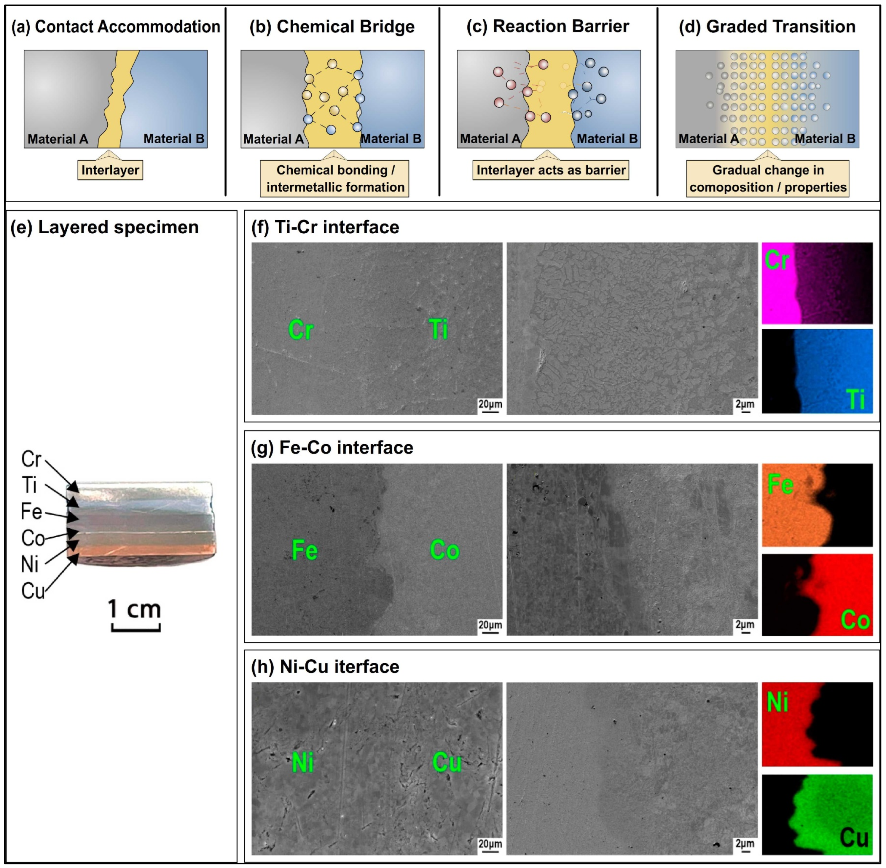
Interlayers can perform four primary functions. By accommodating surface irregularities, they can increase the real contact area and facilitate closure of the initial gaps. A suitable composition can form a chemical bridge that supports elemental transport and metallurgical bonding. Barrier layers can limit direct reactions between the base materials. Multilayer and graded transitions are used to spread differences in composition, elastic properties, and thermal expansion over a wider region, thereby reducing local stress concentration [17,18,19,20,35,42,62]. These four functions are shown schematically in Figure 6a, Figure 6b, Figure 6c, and Figure 6d, respectively.
When an interlayer is introduced, the fracture path may shift to a new boundary or reaction region. In the Mg/Al joint, fracture occurred at the CuNi/Ag boundary on the Mg side [35]. In W/Chinese low-activation ferritic/martensitic (CLAM) steel joints, the dominant fracture path followed the W/Nb boundary [62], whereas in the W/MA956 joint, the crack propagated through the Nb/Ni reaction region [63].
In the six-layer Cr–Ti–Fe–Co–Ni–Cu structure, different interfaces developed between adjacent metal pairs within the same layered structure. Figure 6e shows the overall layered structure. Figure 6f–h show the Ti–Cr, Fe–Co, and Ni–Cu interfaces, respectively. SEM and EDS examinations revealed limited Cr transport at the Ti–Cr interface and higher local microhardness than in the base metals. No pronounced elemental transition was reported at the Fe–Co and Ni–Cu interfaces. XRD analyses of separately prepared binary specimens identified TiCr2 in the Ti–Cr system, whereas only phases of the constituent metals were found in the Fe–Co and Ni–Cu systems [64].
Figure 6.
Main functions of interlayers in FAST/SPS-processed multi-material metallic systems. (e) Cr–Ti–Fe–Co–Ni–Cu layered structure. (f–h) Ti–Cr, Fe–Co, and Ni–Cu interfaces, respectively, with EDS maps. Panels (a–d) were prepared by the author. Panels (e–h) were adapted from Ref. [64].
In the CuNi/Ag/CuNi sandwich interlayer used in the Mg/Al joint, the Ag foil conformed to the rough CuNi films under pressure and increased the real contact area. The CuNi layers limited direct interdiffusion between Mg and Al, and no distinct brittle Mg–Al intermetallic layer was observed at the SEM/EDS scale examined. A shear strength of 50.2 MPa was obtained at 400 °C, 10 min, and 5 MPa. Fracture occurred at the CuNi/Ag boundary on the Mg side [35]. The authors interpreted this fracture path as evidence of weaker bonding on the Mg side than at the corresponding CuNi/Ag boundary on the Al side. They also reported greater Al diffusion into the CuNi layer on the Al side, which was consistent with this interpretation [35].
In 5A06 aluminum-alloy joints, the effect of the interlayer was not limited to its ability to disrupt the oxide film. Mg2Si morphology and post-bond heat treatment also changed the mechanical response. The low-yield-strength 1060 Al interlayer increased surface accommodation and facilitated disruption of the oxide film. After bonding, recrystallized grains crossing the interface and fine, dispersed Mg2Si particles were observed, and the tensile strength was 158.4 MPa. Post-bond heat treatment dissolved the Mg2Si particles, increased grain-boundary migration, and raised the strength to 189.2 MPa. In the joint with a 4004 Al–Si–Mg interlayer, continuous Mg2Si regions formed, and the tensile strength was 55.3 MPa. Heat treatment partially dissolved these regions and increased the strength to 108.7 MPa [14].
7.2. Chemical Bridge, Barrier, and Two Interfaces
The 30 µm Ni foil used in the Cr0.8FeMnNi/316 stainless steel joint created more regular compositional transition regions on both sides and improved chemical and mechanical compatibility relative to the direct joint. The oxide particles at the interface became smaller. The interpretation that the Ni interlayer promoted diffusion and made the local mechanical transition more gradual is based on these observations. At 820 °C, the tensile strength and elongation reached the 316 stainless steel base-metal level. Fracture occurred within the 316 stainless steel, and the interfaces adjacent to the Ni foil did not constitute the weakest region in this test [42]. Although the Ni foil created new boundaries in this system, it did not shift the fracture path to the interlayer.
The two boundaries of the interlayer in the W/CoCrFeNi/steel joint did not develop in the same manner. The Fe, Co, Cr, and Ni concentrations at the steel/CoCrFeNi boundary showed a continuous transition, and the region was interpreted as a solid solution. The diffusion and reaction regions on the W/CoCrFeNi side widened with increasing temperature. Small Kirkendall voids were observed at 1000 and 1100 °C [20].
Replacing the direct W/steel interface with an interlayer did not eliminate the fracture path; instead, it shifted the weak region to new boundaries and reaction regions. In the W/CLAM steel joint, a single Nb foil increased the shear strength from 139.5 ± 3 MPa for the direct joint to 172.3 ± 9 MPa. The Nb/Ni multilayer interlayer formed an Nb–Ni diffusion region approximately 13 µm thick and yielded a shear strength of 166.1 ± 11 MPa. In both architectures, the dominant fracture path followed the W/Nb boundary, and local fracture of W was observed in some regions [62]. In the W/MA956 joint, the Nb/Ni composite interlayer increased the average shear strength to 270 ± 30 MPa. Fracture occurred in the Nb/Ni reaction region, where the Ni6Nb7 and Ni3Nb phases were identified [63].
Interlayer selection changed not only the reaction region but also the fracture path and thermal-shock behavior in W/steel joints. In the W/MA956 joint with an Fe/V composite interlayer, the Fe layer limited carbon transport on the steel/V side, while higher bonding temperatures promoted interdiffusion at the V/W interface [55]. A 40 µm Ti interlayer used with the same material pair formed a solid-solution transition at the W/Ti boundary and a reaction region containing FeTi, Fe2Ti, and Cr2Ti at the Ti/MA956 boundary. The highest shear strength was 228 MPa at 900 °C, and fracture occurred in the Ti/MA956 reaction region [65]. In the pulse plasma sintering study in which W/EUROFER97 joints were prepared with Fe, 86FeTi, and Ti powder interlayers, the joint containing Fe showed greater thermal-shock resistance than the joint containing 86FeTi. Cracks were observed near the Ti/steel interface in the joint with a Ti interlayer [66].
7.3. Stress Accommodation, Layer Sequence, and Thickness
In W/steel fusion-armor studies, V layers and transitions with a gradual variation in W fraction were used to reduce abrupt changes in properties. Although direct W bonding was achieved, non-ideal interfacial contact and the thermal penalty associated with additional layers and interfaces remained important limitations [67,68]. The two publications reported overlapping high-heat-flux results from the same experimental program [67,68].
Another graded structure, produced from Ti–Ni strips stacked in compositional order, developed a composition gradient through the thickness and exhibited a broadened martensitic transformation range [69]. In this example, grading was used to tailor functional transformation behavior over a wider temperature range.
Stacking powders as separate layers produces a stepped composition profile rather than a continuous gradient. In these structures, hardness and densification varied between layers. The hardness profile may track changes in the local microstructure, but it does not directly provide bond strength. In Ref. [68], an approximately 0.3 mm-thick V filler layer was required to bond the plasma-sprayed graded structure to the W tile, whereas the SPS-produced graded structure could be bonded directly. A 1.5 mm-thick V interlayer was used in a separate design [68]. In the six-layer Cr–Ti–Fe–Co–Ni–Cu structure, the adjacent metal pairs showed different interfacial behavior, and diffusion was absent or limited at several boundaries [64]. In the mechanically alloyed five-layer 316L/W structure, powder pretreatment altered the transition band, local phases, and hardness profile [70]. These examples show that multilayer stacking can retain a stepped composition profile and layer-to-layer interfaces.
Interlayer thickness is not merely a geometric variable. It should be selected together with the chemical and thermal function of the layer. For the 0.1 mm Nb and Ni foils used in Ref. [62], different diffusion and reaction structures developed at the W/Nb, Nb/Ni, and Ni/steel interfaces. Graded and multilayer architectures may also increase the total thermal resistance [68]. In Fe-8Cr-xNi graded steels, the Ni profile changed the microstructure and local mechanical response, while the layer-thickness distribution changed the compressive response [71]. In the SUS316L/IN718 system, direct bonding and the six-layer SPS architecture produced different transition structures [72]. Layer sequence also affects the interfaces that form. The reverse sequence cannot be assumed to produce the same result. In the Fe/V architecture, Fe was placed on the steel side and V on the W side, and different reactions developed at the steel/V and V/W boundaries [55].
In the W/Cu/EUROFER97 system, the highest shear strength was obtained at 5 min, while at 9 min, strength decreased, coinciding with greater porosity at the EUROFER97/Cu interface [19]. In the W/CoCrFeNi/steel system, small voids formed at the CoCrFeNi/W interface at high temperatures [20]. In both studies, the pore/void formation was associated with the Kirkendall effect arising from unequal atomic diffusion rates [19,20]. In both examples, the boundaries created by the interlayer changed with processing time or temperature, and new defect regions emerged.
7.4. Verification of Interlayer Contribution
The contribution of an interlayer can be assessed more reliably by comparing direct and interlayered joints of the same material pair under similar FAST/SPS cycles. The meaning of a change in strength should be interpreted in relation to the microstructures of the interfaces created by the interlayer and the fracture location. Although fracture in the base material shows that the interface carried the applied load under that test configuration, it does not provide the actual interfacial strength. An increase in mechanical strength is not sufficient for an application if it is achieved at the cost of reduced thermal performance or loss of joint stability under service conditions.
8. Defects, Residual Stresses, and Damage Development
8.1. Incomplete Contact, Pores, and Spatial Heterogeneity
Interfacial voids do not have a single origin. Surface protrusions or insufficient pressure may leave unbonded areas [52,73]. In powder-containing regions, incomplete densification may preserve pores between particles [31,73]. In some systems, unequal atomic fluxes have also been associated with void formation [19,52]. Defects that appear similar in cross-section do not respond in the same way to processing variables. Incomplete contact is associated with surface condition and applied pressure, pores in powder-containing regions with particle size and densification, and transport-induced voids with unequal diffusion rates. The location of a defect, the surrounding phases, and its evolution during processing help distinguish its origin from its mechanical effect. Describing all defects simply as “porosity” makes it difficult to distinguish different mechanisms. Multiple mechanisms may coexist in the same joint.
In the powder/solid repair of W–30Si, the joint failed to form when no holding time was applied. A continuous joint developed after a 10 min hold, whereas Si loss occurred after 20 min [73]. The relative density of more than 100% reported for the final condition cannot be used directly as a measure of densification because of material loss. Incomplete joining characterized the shortest condition, whereas Si loss compromised the 20 min condition.
In rapid joining with a 316L powder interlayer, some lower-power/longer-time combinations were associated with cracks, whereas coarse powder increased residual porosity. With fine powder, fracture occurred both at the joint and in the base material, and most samples under the selected power–time conditions fractured in the base material, whereas excessive pressure or unsuitable power–time combinations were associated with macroscopic deformation. Their separate effects cannot be resolved because the actual interfacial temperature, interlayer thickness, and number of replicates are not specified [31].
A single central cross-section may not represent the entire joint. In joining trials used to develop the plasma-sprayed graded W/steel architecture, good bonding over much of an interface could coexist with unbonded or delaminated regions near the edges. Microstructural examination of multiple regions revealed this heterogeneity. Because no direct strength test was performed, local metallurgical bonding does not demonstrate the load-bearing capacity of the entire joint [30].
8.2. Transformation of Defects During Processing
When processing conditions change, both the extent and the dominant type of defects may change. Low temperature, short time, or insufficient pressure may leave areas of incomplete contact and inadequate metallurgical bonding. These defects may decrease as temperature, time, or pressure increases. By contrast, microstructural changes in the base material [44], macroscopic deformation [31], or brittle reaction layers [55] may develop. The lowest visible porosity does not always correspond to the most suitable condition. An appropriate processing window is one in which the interface is closed while changes in the base material and transition regions remain limited.
Tan et al. [44] examined this balance in similar-material W/W foil laminates joined at different temperatures. Figure 7a–e show the 600, 800, 1000, 1200, and 1400 °C conditions, respectively. Pronounced gaps are visible in Figure 7(a1,b1), and the inset of Figure 7c. No distinct interfacial gaps are visible in the insets of Figure 7d,e. Recrystallization began at 600 °C, and the foils were reported to be fully recrystallized in the specimens processed at 1000 °C and above. A pronounced decrease in hardness was also observed at approximately 1000 °C. Thermal diffusivity was similar for the 1200 and 1400 °C conditions. By considering contact development together with the microstructural change in the foils, the authors selected 1200 °C as the appropriate joining temperature. Thermal diffusivity was used as an indirect measure sensitive to interfacial gaps, whereas joint strength was not measured directly [44].
Figure 7.
Cross-sectional metallographic images of tungsten foil laminates joined by FAST at different temperatures: (a) 600 °C; (b) 800 °C; (c) 1000 °C; (d) 1200 °C; and (e) 1400 °C. Subfigures (a1,b1), and the inset images in (c–e), show higher-magnification scanning electron microscopy (SEM) images of the corresponding interfaces. Reprinted from Ref. [44].
Elimination of interfacial voids is not sufficient to establish mechanical integrity. The mechanical effect of reaction products can be interpreted together with the crack path and fracture region. In the W/V/ODS steel joint, the continuous V2C layer at the steel/V interface acted as the crack-initiation region, and the crack propagated along the V interlayer toward the V/W interface. Secondary microcracks associated with insufficient interdiffusion also formed at this boundary. The brittle V2C layer and insufficient interdiffusion on the V/W side contributed to the same damage path. A generally applicable critical V2C thickness cannot be derived from a single study [55].
In the W/Cu/EUROFER97 system, increasing the holding time to 5 min improved the joint. At 9 min, however, strength decreased, coinciding with greater porosity at the EUROFER97/Cu interface. The porosity was attributed to the Kirkendall effect based on its location and geometry and the reported disparity in Fe–Cu diffusion coefficients, but no marker experiment was reported [19]. In the HNBG/Ni/IN718 system, increasing temperature, time, or pressure reduced the Kirkendall voids and made the Kirkendall interfaces less distinct. Nevertheless, fracture occurred in the γ′ or τ3 diffusion layers, depending on bonding temperature [52].
8.3. Residual Stress and Damage During Service
Residual stress was inferred indirectly from thermal expansion mismatch or edge delamination during cooling in some studies [30], whereas it was measured directly in others [74]. In a study on FAST bonding and forging of Ti alloys, X-ray diffraction and the contour method were both used to measure residual stress, but X-ray diffraction resolved the narrow bond regions more effectively. For the specimen designated FDB3 in Ref. [74], residual stress was evaluated by XRD, and peak values of approximately −500 MPa in compression and +300 MPa in shear were reported. These localized residual-stress peaks indicate a non-uniform stress state in the bond region that may influence its mechanical response during subsequent loading. A specific relationship between the −500 MPa compressive and +300 MPa shear peaks and joint strength or failure behavior was not reported for FDB3 [74]. For FDB3, overlapping X-ray diffraction measurements could average out highly localized stresses within the narrow diffusion region; geometry-related stress variations and cutting-related artifacts were reported separately for the forged contour-method measurements. In other systems, a continuous V2C layer was identified as a crack-initiation site, while continuous Mg2Si regions contained microcracks and provided a preferred crack path [14,55]. Taken together, these observations suggest that a continuous brittle phase [14,55] may be more susceptible to crack initiation when it coincides with a localized tensile component of the residual-stress field [74]. This stress–phase interaction was not measured directly in the cited systems [14,55,74]. In a direct 75W/bulk-W joining trial used to develop the plasma-sprayed graded W/steel architecture, regions near the edges remained unbonded or delaminated during cooldown. The delamination is consistent with residual-stress development during cooling. Because the stress was not measured directly, this mechanism could not be confirmed [30].
Joints may show no clear degradation during cycling at lower heat loads yet fail or degrade markedly when a new, slightly higher power level is applied. In high-heat-flux tests of W/steel joints, failure often occurred during the initial screening or first cycles at the new power level. Manufacturing-related voids, cracks, or lack of metallic bonding acted as thermal barriers and were associated with higher-than-predicted temperatures. Residual stress was not measured directly. The heat-flux values at which failure occurred in small-scale experiments cannot be regarded directly as service thresholds for demonstration fusion power plant (DEMO) conditions [67].
8.4. Evaluation of Defects
A single central cross-section may not be sufficient to show how defects are distributed along the joint. Their location, morphology, and relationship to neighboring phases can influence the crack path [19,30,55]. In Ref. [19], localized interfacial porosity and porosity that became continuous along the interface were associated with different mechanical responses. The area examined and the scale of observation should therefore be considered when microstructural evidence is used to characterize defects [30]. A microstructurally “defect-free” interface does not by itself establish mechanical integrity [55].
9. Mechanical Integrity and Fracture Paths
The mechanical integrity of an interface cannot be described by strength alone. The meaning of a result depends on the loading mode, specimen geometry, load-bearing area, test temperature, and fracture location. Tensile and shear values reported in the same units represent different stress states. Comparison requires knowing which response was measured and which region controlled fracture.
9.1. Test Geometry and Fracture Location
Tensile, shear, bending, compression, and special separation tests create different stress states at the interface. Free edges, overlap length, specimen cross-section, load-bearing area, and fixture behavior affect the measured nominal stress. In multilayer systems, the actual interfacial stress is generally not uniform. Direct comparison of values obtained with different geometries and at different temperatures may be misleading. The maximum load measured in a special setup also cannot be converted to tensile or shear strength without knowing the geometry and effective area.
In Ti-6Al-4V/Ti-6Al-4V joints, room-temperature tensile strengths of 789 and 826 MPa were measured for specimens joined at 600 and 650 °C, respectively, and fracture occurred at the joint. For the specimen joined at 700 °C, the tensile strength was 893 MPa and fracture occurred in the base material. Although this value does not provide the actual interfacial strength, it shows that the interface sustained the applied load corresponding to a nominal tensile stress of 893 MPa under this test configuration. In a separate series produced using a graphite die, fracture occurred at the joint for specimens joined at 750 and 800 °C, whereas base-material fracture occurred for the specimen joined at 850 °C [75].
In the same tensile test series for oxygen-free copper (OFC)/SUS304 joints bonded under 20 MPa, tensile strengths of 36 and 86 MPa were reported for specimens bonded at 773 and 873 K, respectively. The fracture surfaces were relatively smooth at 773 K and showed different morphologies between the center and outer edge at 873 K. At 973 K, the tensile strength reached 222 MPa and fracture occurred in the OFC base material [76]. When fracture occurred in the base material, the interface did not control failure at the applied nominal tensile stress. The increase in strength across the series occurred together with changes in fracture-surface morphology and culminated in fracture in the OFC base material.
In the Cr0.8FeMnNi/316 stainless steel joint with a Ni interlayer bonded at 820 °C, the tensile strength and elongation reached the 316 stainless steel base-metal level, and fracture occurred within the 316 stainless steel rather than at the interface [42]. By contrast, fracture occurred at the interface at approximately 468 MPa in the CoCrFeNiMn/316 stainless steel joint [49]. Because the fracture paths differed, these results cannot be used to establish which interface was stronger.
9.2. Shear and Special Loading Configurations
Under the general heading of shear, different tests are used, including lap-shear, compression-shear, push-out, and tests based on special fixtures. The stress in these setups is generally not distributed uniformly. In the W/CLAM steel joint, the direct, single-Nb-foil, and Nb/Ni multilayer architectures produced shear strengths of 139.5 ± 3, 172.3 ± 9, and 166.1 ± 11 MPa, respectively. Despite the increase in strength, the dominant fracture path in both interlayered architectures followed the W/Nb boundary, and local W regions were visible on the fracture surface of the Nb/Ni multilayer joint [62].
In special tests, the instrument limit and the definition of the measured quantity determine how the result should be interpreted. The Cu–Zn brass/SCM435 joint did not fracture up to the instrument limit in a special axial separation test and reached a nominal stress of at least 432 MPa in that geometry [77]. In the Al7075/Cu/Ti-6Al-4V system, one specimen was tested for each process condition, and the reported strength was defined as the stress corresponding to the maximum load. This result cannot be classified as tensile or shear strength because the loading configuration, stress-calculation basis, and test standard are not specified [78].
9.3. Bending, Local Measurements, and Fracture Evidence
A three-point bending test measures the overall structural response of the layered specimen rather than the behavior of the interface alone. In [79], a three-point bending flexural test was used to evaluate the strength of the sintered samples. For these Ti-based laminates, the full specimen geometry, support span, and condition-specific fracture path are not specified. The reported results therefore represent the bending response of the laminate rather than a direct measure of interfacial strength [79].
Nanoimpact, nanoindentation, and microhardness measurements provide information on local mechanical behavior around the interface. The nanoimpact results in the Ti-6Al-4V/steel study described the dynamic response of the region near the interface but did not provide a direct bond-strength measurement. The material identity of the interlayer was not specified, although its thickness was reported as 5–50 µm [80]. The nanoimpact measurement length scale was reported as 1–5 µm, whereas the Vickers measurement length scale was a few hundred micrometers. The Vickers test conditions are not reported in comparable detail, which limits direct quantitative comparison with the nanoimpact dynamic-hardness values [80].
The macroscopic fracture location does not always reveal the actual crack path. Local fractography can show whether a nominally interfacial crack remains at the interface or shifts into one of the adjoining materials. Fractography and fracture-surface chemistry help distinguish these paths more reliably.
In the W/Cu/EUROFER97 joint studied by Sánchez et al. [19], fracture after shear testing propagated mainly along the EUROFER97/Cu interface and crossed over to the W/Cu side in some regions. Most of the Cu interlayer remained on the W surface, while a central portion was found on the EUROFER97 side. Figure 8a,b show the opposing fracture surfaces. Figure 8c,d show details of the selected regions. The contrast difference in Figure 8c was interpreted as a region detached from the W base material. When the crack reached the W/Cu boundary, it locally deflected into W rather than propagating along the interface. Intergranular fracture was observed in the W base material in Figure 8d. The crack path therefore changed along the joint, and the base material contributed to damage in some regions.
Figure 8.
Fracture surfaces of the FAST-joined W/Cu/EUROFER97 joint after shear testing: (a) EUROFER97 fracture surface; (b) tungsten fracture surface; (c) detail of zone 1 marked in (a); and (d) detail of zone 2 marked in (b). Reprinted from Ref. [19].
The holding time represented by these images (2, 5, or 9 min) is not identified. Because of this uncertainty, the panels provide a mechanistic example of how the crack path can vary within the joint rather than evidence of strength for a specific processing condition [19]. XRD examination of the fracture surfaces identified Cu, Fe, and W peaks on the EUROFER97 side, but only Cu peaks on the W side. The W peaks on the EUROFER97 surface were associated with W fragments detached from the W base material and retained on the opposing surface, and no new reaction product or intermetallic phase was detected [19].
Nominal strength should be interpreted together with the fracture mode. Mixed fracture does not provide a pure measure of interfacial strength. A crack entering the base material indicates that the interface was not the weakest path under the test conditions, but it does not determine the actual interfacial strength. If no fracture occurs before the instrument limit is reached, the result shows only that the specimen withstood the applied load in that test configuration.
Ratios reported as joint efficiency become meaningful when the joint and the base material are measured under the same test conditions. The FAST/SPS cycle may anneal the base material, cause grain growth, or alter the precipitate structure. A ratio calculated using the strength of the base material in its initial condition may therefore overestimate or underestimate joint performance.
9.4. Temperature, Replication, and a Reliable Processing Window
The thin γ/γ′ region between single-crystal and polycrystalline Ni-based superalloys carried high loads at room temperature. By contrast, the weakest region shifted to the interface after double-aging heat treatment and testing at 700 °C. Because the bond region was not sectioned directly after aging, the interpretation of the associated microstructural evolution is based partly on inference from model specimens [41]. In this example, the short-term room-temperature results were not sufficient to predict the fracture path after subsequent aging and high-temperature testing.
Multiple specimens extracted from the same joint and their error bars describe within-joint specimen-to-specimen scatter. They do not, however, show that the specimens came from separate production cycles. Process reproducibility is better assessed by reproducing similar microstructures and fracture behavior in separate production runs. A single highest value does not reflect scatter between production runs or the distribution of fracture locations. Results provide stronger evidence when the test geometry and load-bearing area are described, the fracture path is examined by fractography, and the findings are related to the microstructure. Predictable load transfer at the target temperature and limited brittle crack propagation are as important as nominal strength.
Interfacial defects that affect mechanical integrity can also influence thermal or electrical transport. Thermal cycling and corrosion may further alter the damage state, so mechanical integrity should be considered together with thermal, electrical, and environmental service performance.
10. Thermal, Electrical, and Environmental Service Performance
The service behavior of a joint that provides mechanical integrity at room temperature may change under heat flow, electric current, and environmental exposure. Real contact area, pores, reaction products, interlayer thickness, and component geometry can affect thermal or electrical transport. Corrosion and thermal cycling may also alter the damage state of a joint that initially appears stable. Evaluation of service performance requires application-relevant thermal, electrical, or environmental measurements in addition to mechanical tests.
10.1. Functional Performance and Thermal Transport
Transport and damage criteria vary with the application. Contact resistance is important in electronic packages. Temperature rise and separation are monitored in fusion components, whereas crack development and cross-sectional damage are monitored in corrosive environments. High mechanical strength does not necessarily coincide with low thermal or electrical resistance. A thicker or graded transition region may improve stress accommodation but can also raise temperatures in the stack. Coupon conductivity does not provide the total thermal resistance of a cooled module, just as package-level electrical response does not provide the resistivity of a single interface.
Thermal conductivity and diffusivity are sensitive to interfacial voids, low-conductivity phases, and matrix heterogeneity, but they do not directly provide interfacial thermal resistance. In the W–75Cu/CuCrZr system, the fabrication temperature was increased from 850 to 950 °C. Thermal conductivity measured at 400 °C also increased from 210.5 W/(m·K) to 237.9 W/(m·K). When the fabrication temperature was increased to 1000 °C, the value decreased to 225.7 W/(m·K), together with W agglomeration and porosity [81].
The highest thermal conductivity and the highest nominal shear value were obtained at 950 °C. A maximum shear strength of 216.5 MPa was reported under this condition. Fracture occurred mainly within the W–75Cu matrix, and the interface was not the observed fracture location at this nominal stress level. Under the 1000 °C condition, where W agglomeration and porosity were observed, both thermal conductivity and the nominal shear value decreased [81].
Thermal diffusivity in a 21-layer W foil laminate was measured from room temperature to 450 °C at 50 °C intervals. Significant interfacial gaps were present between the foils in specimens joined at 600, 800, and 1000 °C [44]. Diffusivity is a sensitive indicator of these defects, but it cannot be interpreted directly as interfacial thermal resistance or bond strength.
10.2. Integrity After Thermal Cycling
In the W–75Cu/CuCrZr joint fabricated at 950 °C, the nominal shear strength decreased from 216.5 to 172.7 MPa after 200 cycles between 450 °C and room temperature, and no visible interfacial crack was observed. Each cycle consisted of a 10 min hot hold followed by 5 min of water cooling [81]. Because no post-cycling thermal conductivity measurement was reported, preservation of thermal transport at the same level was not confirmed. In the ODS-W/TZC joint, interfacial microstructure, mechanical response, and thermal-shock behavior were evaluated in the same study. The data for the joint were obtained from original experiments. The comparison of surface height undulation with bare ODS-W was based on previously reported data rather than measurements generated in the same study [82].
In 1–1.5 mm-thick W coatings produced by FAST on patterned AISI 416 steel, no new cracks formed after 50 cycles between approximately 300 and 800 °C. The initial vertical segmentation cracks were considered part of a strain-relieving architecture. The 2 mm-thick coating completed the cycling, but a small segment debonded during handling after the test [45]. Crack count alone is not a failure criterion. Crack orientation, stability, and whether the cracks lead to separation also matter. Heat flux was not quantified, and the infrared images were used qualitatively without emissivity calibration. The post-cycling assessment was based on visual evidence of cracking and debonding rather than on a bond-strength measurement [45]. No failure was observed in the direct FAST joint between W–11.4Cr–0.6Y and EUROFER after seven thermal cycles between 573 and 873 K. Because the number of cycles was limited and the thermal cycling was mild, this result shows only short-term integrity under the conditions examined [83].
10.3. Electrical and Multifunctional Results
Few FAST/SPS studies have directly examined electrical service behavior. The available results mostly describe package-level response or local properties within a graded body. Cu-micropost/direct-bonded copper (DBC) sandwich packages incorporating direct Cu/Cu contacts were evaluated electrically at the package level, while sandwich assemblies were subjected to shear testing. The electrically characterized packages were bonded in a rapid thermal annealing furnace, whereas the shear-test assemblies were bonded using either a spark plasma sintering press or a rapid thermal annealing furnace [3]. The measured response could include contributions from the effective Cu-post/DBC bonded area, the surface condition of the bonded Cu surfaces, the Ti/Cu seed metallization, including the strongly oxidized Al/Ti interface, the underlying Ag–Cu joint, and the entire package stack. This measurement represents the electrical response of the package stack rather than the resistivity of the Cu/Cu contact alone. The bulk Cu/Cu comparison reported in [3] relied on results from the earlier bulk-copper study [29].
In the as-SPS Fe–Co–Ni graded structure, resistivity was reported as 10.8 µΩ·cm at the Co-rich end and 14.8 µΩ·cm at the permalloy-rich end. Saturation magnetization, coercivity, and Curie temperature showed graded profiles across the composition gradient [84]. The property values were obtained from compositional sections of a single SPS-processed graded sample rather than from independently produced composition-specific specimens. The graded sample was vertically divided, and one section was annealed at 900 °C for 10 h [84]. Annealing reduced hardness and resistivity. Coercivity generally decreased after annealing, although it increased slightly for Co. This was a characterization study in which local properties were measured across the graded body, not a service test. The Curie-temperature profile was shown for the graded SPS-processed sample. The annealed-property comparison also included Curie temperature, but it is unclear whether this was remeasured after annealing [84].
10.4. High-Heat-Flux and Component-Level Validation
High-heat-flux tests allow the ability of a joint to remove heat and the development of damage during cycling to be monitored together. Dorow-Gerspach et al. [67] compared W/EUROFER97 joints from 1 to 5 MW/m2 in increments of 0.5 MW/m2, with up to 200 cycles at each step. The direct joints sustained damage in regions near the W–steel boundary at 4–5 MW/m2. The W surface temperature increased by approximately 200 °C for every 1 MW/m2 increase in heat flux. For the best-performing direct joint, failure initiated at the highest heat-flux level reached by the direct-joint series. The estimated temperature at the W–steel interface at failure initiation was approximately 880 °C. This value was not measured directly but was estimated using the surface temperature and a thermal model [67].
Ganesh et al. [68] presented detailed temperature distributions, cycle lives, and damage regions for four joint architectures also examined by Dorow-Gerspach et al. [67]. The data reported by Ganesh et al. overlapped with the broader experimental dataset later reported by Dorow-Gerspach et al. Therefore, the overlapping results cannot be treated as independent validations. The comparison included a joint containing an atmospheric-plasma-sprayed functionally graded material (FGM-APS) and a joint containing an SPS-produced functionally graded material (FGM-SPS). The other two architectures were a joint with a 1.5 mm-thick V interlayer and a direct W–steel joint [68].
Figure 9a,b show the W surface-temperature distributions during the first and 200th cycles, respectively, at the 2.5 MW/m2 step. The surface temperature increased by approximately 100 °C in two FGM-APS specimens, but no distinct local hot spot formed. The authors suggested that the increase reflected uniform deterioration of the joint, such as a reduction in the thermal conductivity of the interlayer, rather than the development of a local crack at the bonding seam. In the FGM-SPS joint, the temperature distribution became nonuniform at 1.5 MW/m2. This was interpreted as evidence of cracking at the bonding seam and partial detachment of the W tile. At the beginning of the 2 MW/m2 step, the surface temperature increased sharply and the joint ultimately failed completely. The high surface temperature in FGM-SPS was attributed to inadequate bonding between W and the FGM, which limited heat removal [68].
Figure 9.
Steady-state W-tile surface-temperature maps during (a) the first and (b) the 200th cycle of the 2.5 MW/m2 loading step. The maps show the positions of atmospheric-plasma-sprayed functionally graded material (FGM-APS), SPS-produced functionally graded material (FGM-SPS), V(0.3), V(0.8), V(1.5), and direct W/EUROFER97 specimens. A, B, and C identify the three specimens tested for each joint configuration. The FGM-SPS specimens had failed before the 2.5 MW/m2 step. (c) Lifetime of the FGM-APS, FGM-SPS, V(1.5), and direct joints plotted against cumulative cycle number. In panel (c), each cross represents the lifetime of an individual specimen, and the shaded regions indicate scatter. Adapted from Ref. [68].
Thermal images from the same experimental series also included specimens with 0.3 and 0.8 mm-thick V interlayers. The cycle-life graph in Figure 9c, however, was limited to the FGM-APS, FGM-SPS, V(1.5), and direct joints. FGM-SPS showed the shortest cycle life. FGM-APS and V(1.5) reached similar cycle lives, whereas the direct joint had the longest life within this group [68].
The damage region varied with the architecture. The FGM-SPS joint sustained damage at the boundary between W and the upper FGM layer. Damage in the V(1.5) joint occurred mainly in the V region near the W/V line. In the FGM-APS structure, cracks developed mainly in the plasma-sprayed 75W layer and the V interlayer. Damage in the direct joint occurred in the region near the W–steel boundary [68]. High-heat-flux behavior depends on more than grading alone. Contact quality on the W side, the total thermal resistance of the layers, and weak regions created by the architecture also affected the outcome.
The heat flux at which damage began in these experiments cannot be explained by the interface material alone. The joints were brazed to actively cooled Cu supports, the temperature was measured at the W surface, and interface temperatures were estimated using a thermal model. The W and steel layer thicknesses, interlayer architecture, steel–Cu support braze, and cooling arrangement were all part of the specimen geometry and thermal path. Initial defects and non-ideal contacts could also influence heat transfer and failure behavior. The measured cycle life and heat flux at damage initiation reflect the specimen geometry and test setup as well as the joint [67,68].
10.5. Environmental Degradation and Service Trade-Offs
A reaction or diffusion region that appears beneficial during bonding may become a selective degradation path in a corrosive environment. Large debonding cracks were observed after 10 days of high-temperature steam exposure in direct FeCrAl–Zr-2.5Nb joints without post-bond heat treatment and after 21 days in FeCrAl/Si–Zr-2.5Nb joints. Joints heat treated at 1300 °C for 10 min showed severe corrosion of the diffusion layer after one day of steam exposure [85]. These durations do not represent general service life, but the exposure times at which damage was observed under the conditions examined.
In Ti-5Al-2V/Ti-5Al-2V joints, 500 h hot-salt tests associated crevice corrosion with high weld porosity and joint macrodefects. Tafel measurements in ultrafine-grained joints showed a higher mean corrosion current density for high-porosity specimens than for specimens with low or intermediate porosity. Porosity also changed with other microstructural features across the processing conditions, so its individual contribution was not separated. Current density was reported mainly in mA/cm2, with one statement using µA/cm2. The relative trend remains informative despite this unit difference. The explanation that porosity increased the effective surface area was supported indirectly by the observed dependence on porosity. Reproducibility was assessed by repeating the i(E) measurements three times for each specimen. Several specimens were also compared for one stated processing regime [86]. Hot-corrosion tests on NiCrAlY and the high-entropy alloy (HEA)-based HEA-15 and HEA-15F joint systems were conducted at 800 °C. After 40 h, oxide layers approximately 239, 98, and 94 µm thick, respectively, had formed. Although the HEA-containing architectures formed thinner oxide layers, cracks were observed in HEA-15F, and severe damage developed in all systems after 100 h [23]. The presence of cracks despite the thinner oxide layer shows that environmental integrity cannot be evaluated by layer thickness alone. Cross-sectional damage should also be considered. Hot-corrosion performance was assessed from weight change, oxide-layer thickness, and cross-sectional observations [23].
Functional design can involve a trade-off between stress accommodation and thermal or electrical series resistance. A thick or graded transition region may reduce abrupt changes in thermomechanical stress. By contrast, additional low-conductivity or poorly bonded layers can raise temperatures and reduce power handling [67]. Reaction and diffusion regions may become new degradation paths under environmental exposure [85]. Additional layers may also alter thermal or electrical response [3,67]. Thermal conductivity, diffusivity, and interfacial thermal resistance are different quantities and cannot be used interchangeably. A high value obtained at the coupon level does not replace cyclic or environmental component validation. Interpretation of service behavior depends on relating functional measurements to microstructural findings before and after testing and to the location of damage.
11. Design Principles and Research Needs
An appropriate processing condition for an interface produced by FAST/SPS cannot be selected solely on the basis of the highest density or nominal strength value. The joint must maintain its integrity and required function under the target temperature, loading, and environmental conditions. The choice among direct bonding, an interlayer, or a graded transition for a material pair should be based on the service conditions and expected mode of damage.
The effect of the processing window varies with the selected architecture. Interlayers may improve contact accommodation and compositional transition [17,18,19,20,35,42,62], but additional reaction regions or porosity may also develop [18,19,20,62]. Heat removal may be impaired in graded and multilayer transitions [68]. Increasing temperature, time, or pressure may improve interfacial contact or interdiffusion while increasing the risk of brittle-phase growth, Kirkendall porosity, or cracking [18,19,20,42]. Evaluation of the processing window therefore considers real contact, reaction regions, defects, fracture path, and service behavior alongside visible interfacial continuity. The evaluation flow is summarized in Figure 10.
Figure 10.
Evaluation flow for interface design and service validation in FAST/SPS-processed multi-material metallic systems.
11.1. Design and Validation Principles
The success criterion varies by application. In electronic packages, total resistance and package integrity are important [3]. In fusion components, thermal transport under high heat flux [67] and integrity during thermal cycling [81,83] are emphasized. In corrosive environments, interfacial integrity after exposure is evaluated [23,85,86]. These criteria test different dimensions of performance. Base-material fracture, loads measured with special fixtures, bending behavior, local nanoimpact response, and microstructural continuity are also different types of evidence. They do not measure the same physical property [41,42,49,62,75,76,77,78,79,80].
Contact, chemistry, and architecture complement one another, but each requires separate evidence. Nominal pressure and total displacement do not directly indicate local contact continuity [30,50]. EDS/EPMA, XRD, WDS, and TEM/HRTEM provide complementary information on composition, phase, and crystallography at different scales [15,16,48,49,50,54,59]. Without a test result and fracture location, the mechanical significance of these findings cannot be fully determined. The effect of an interlayer also cannot be explained by composition alone. Layer sequence, initial interlayer thickness and resulting diffusion/reaction-layer thicknesses, interfacial phases, defects, and fracture path should therefore be considered together [35,62,63,64].
Voids with a similar appearance may not have the same origin. Incomplete contact, insufficient powder densification, unequal atomic flux, or separation during cooling may produce similar images [20,45,86]. The location of the defect, its evolution with processing, and its relationship to the crack path are used to distinguish its origin from its mechanical effect. Electrical, thermal, high-heat-flux, and environmental tests probe different dimensions of service-relevant performance [3,23,44,45,67,81,83,85,86]. Relating post-exposure functional results to the microstructure and damage location facilitates interpretation of the source of damage [23,67,81,85,86]. The main dimensions addressed in design and validation, the evidence used, and the interpretive limits of that evidence are summarized in Table 1. Key processing conditions, interfacial observations, and reported outcomes for the principal material systems discussed in this review are summarized in Table 2.
Table 1.
Common evaluation criteria for FAST/SPS interfaces.
Table 2.
Summary of processing conditions, interface observations, reported properties, and application-relevant limitations for key FAST/SPS-processed multi-material metallic systems.
11.2. Limitations of the Review
Differences among material pairs, equipment, geometries, and test methods hinder direct quantitative comparison. Only a subset of studies evaluate performance under service-relevant conditions. Rather than general quantitative thresholds or a single universal processing window, the reviewed evidence provides a framework for the questions to be addressed and the appropriate measurements to be used in studies of new material systems.
11.3. Future Work
Future studies should determine the actual interfacial temperature and the current passing through the specimen more directly during FAST/SPS. When current-specific effects are investigated, local temperature and current measurements should be combined with an appropriate zero-current comparison. This can help distinguish thermal effects from possible athermal contributions more reliably [24,25].
Process reproducibility should be evaluated using independent production runs. Under the same processing condition, the initial surface condition, center-to-edge variation, compositional transition, phases, defects, and fracture path should be examined together.
FAST/SPS studies should use common testing and reporting practices to improve cross-study comparability. Where specimen geometry permits, room-temperature tensile tests should follow ISO 6892-1 or ASTM E8/E8M [87,88]. Elevated-temperature tensile tests should follow ISO 6892-2 or ASTM E21 [89,90]. For butt-type FAST/SPS joints, the specimen-geometry and fracture-location provisions of ISO 4136 may serve as a reference. ISO 4136 applies to welded butt joints, and any adaptation should be stated clearly [91]. Shear, push-out, bending, and special-fixture tests should be compared quantitatively only when test geometry, loading mode, temperature, loading rate, and stress definition are the same or sufficiently equivalent. When no directly applicable standard is available, specimen and fixture geometry, loading conditions, the area and method used for stress calculation, number of specimens, and fracture location should be reported clearly.
The generalizability of a processing window identified using a single equipment configuration or coupon geometry to other equipment and application-representative geometries should also be assessed. Service behavior should not be evaluated only by short-term mechanical tests at room temperature. Depending on the target application, tests should address thermal cycling, high heat flux, electrical behavior, or environmental exposure. When subsequent manufacturing steps such as forging, drilling, or machining are used, interfacial integrity should also be evaluated after these operations [92,93,94].
12. Conclusions
In FAST/SPS, interface development begins with real contact, but whether this contact develops into a load-bearing transition depends on surface condition and interfacial processes. Local deformation can increase contact and disrupt oxide films, whereas persistent oxides can limit metallic bonding. Compositional transitions indicate atomic transport but do not directly define bond quality. Likewise, a broad diffusion zone, grain continuity, high hardness, or an apparently void-free cross-section cannot alone establish high interfacial strength. Reaction regions should be evaluated by considering phase identity, thickness, continuity, morphology, and position along the fracture path.
Interlayers and graded architectures can improve contact and atomic transport, reduce property mismatches, and limit detrimental reactions. They may also create interfaces and reaction regions that redirect fracture. Their effects should therefore be assessed by considering phases, defects, and fracture path rather than strength alone.
Performance should be assessed under mechanical, thermal, electrical, or environmental conditions relevant to the target application. Mechanical integrity cannot be described by strength alone, so fracture location is essential. Base-material fracture shows that the interface was not the weakest path under those test conditions but does not provide actual interfacial strength. If no fracture occurs before the instrument limit is reached, the actual interfacial strength remains undetermined in that test. Across studies, quantitative strength comparisons require sufficiently equivalent test geometry, loading mode, temperature, loading rate, and stress definition.
Appropriate temperature, pressure, and holding time depend on the material system and architecture. Conditions that improve contact may also promote undesirable reactions, voids, or macroscopic deformation. Current-specific effects should be examined using measurements of specimen current and local temperature with an appropriate zero-current comparison to help distinguish thermal from possible athermal contributions more reliably. Processing windows from one equipment configuration or specimen geometry should not be generalized directly. Reproducibility should be evaluated using independent production runs. Each processing window should be validated for interfacial integrity and behavior under target service conditions.
Funding
This research received no external funding.
Data Availability Statement
No new data were created or analyzed in this study. Data sharing is not applicable to this article.
Acknowledgments
The schematic figures were manually drawn by the author. ChatGPT (GPT-5.6 Sol, OpenAI) was used only to discuss conceptual ideas for some schematic illustrations and for English translation and language editing. No AI-generated images or graphical outputs were used in the figures. The author reviewed and edited the output and takes full responsibility for the content of this publication.
Conflicts of Interest
The author declares no conflicts of interest.
References
- Lister, S.; Levano Blanch, O.; Fernández, D.S.; Pope, J.; Baxter, G.J.; Bray, S.; Jackson, M. A Machinability Assessment of the Novel Application of Field-Assisted Sintering Technology to Diffusion Bond (FAST-DB) and Functionally Grade Dissimilar Nickel-Based Superalloys. Metall. Mater. Trans. A 2023, 54, 4396–4408. [Google Scholar] [CrossRef] [Scilit]
- Pope, J.J.; Calvert, E.L.; Weston, N.S.; Jackson, M. FAST-DB: A Novel Solid-State Approach for Diffusion Bonding Dissimilar Titanium Alloy Powders for Next Generation Critical Components. J. Mater. Process. Technol. 2019, 269, 200–207. [Google Scholar] [CrossRef] [Scilit]
- Mouawad, B.; Thollin, B.; Buttay, C.; Dupont, L.; Bley, V.; Fabrègue, D.; Soueidan, M.; Schlegel, B.; Pezard, J.; Crebier, J.-C. Direct Copper Bonding for Power Interconnects: Design, Manufacturing, and Test. IEEE Trans. Compon. Packag. Manuf. Technol. 2015, 5, 143–150. [Google Scholar] [CrossRef] [Scilit]
- Hirose, T.; Shiba, K.; Ando, M.; Enoeda, M.; Akiba, M. Joining Technologies of Reduced Activation Ferritic/Martensitic Steel for Blanket Fabrication. Fusion Eng. Des. 2006, 81, 645–651. [Google Scholar] [CrossRef] [Scilit]
- Yadav, M.K.; Shukla, R.; Xi, L.; Wang, Z.; Prashanth, K.G. Metallic Multimaterials Fabricated by Combining Additive Manufacturing and Powder Metallurgy. J. Compos. Sci. 2025, 9, 80. [Google Scholar] [CrossRef] [Scilit]
- Pripanapong, P.; Kariya, S.; Luangvaranunt, T.; Umeda, J.; Tsutsumi, S.; Takahashi, M.; Kondoh, K. Corrosion Behavior and Strength of Dissimilar Bonding Material between Ti and Mg Alloys Fabricated by Spark Plasma Sintering. Materials 2016, 9, 665. [Google Scholar] [CrossRef] [Scilit] [PubMed]
- Gao, Q.; Zhang, L.; Teng, A. Diffusion Bonding Behaviour of Nb–Si and TiAl Alloys by Spark Plasma Sintering. J. Mater. Res. Technol. 2024, 28, 1803–1809. [Google Scholar] [CrossRef] [Scilit]
- Lin, C.I.; Niuman, S.J.; Kulkarni, A.K.; King, D.S.; Singh, J.; Yamamoto, N. Sintering and Joining of Ni-Based Superalloys via FAST for Turbine Disc Applications. Metall. Mater. Trans. A 2020, 51, 1353–1366. [Google Scholar] [CrossRef] [Scilit]
- Obadele, B.A.; Adesina, O.S.; Oladijo, O.P.; Ogunmuyiwa, E.N. Fabrication of Functionally Graded 316L Austenitic and 2205 Duplex Stainless Steels by Spark Plasma Sintering. J. Alloys Compd. 2020, 849, 156697. [Google Scholar] [CrossRef] [Scilit]
- Wu, T.; Wang, C.; Liu, Y.; Zhang, Q.; Lin, P.; Yue, X.; Lin, T.; He, P. A New Strategy for Preparing High Strength Diffusion-Bonded Ni-Based Superalloy Joints at Ultra-Low Temperature via Surface Nanocrystallization and Spark Plasma Sintering. J. Mater. Sci. Technol. 2025, 226, 181–195. [Google Scholar] [CrossRef] [Scilit]
- Li, W.; Liang, Y.; Bai, Y.; Lin, T.; Li, B.; Fu, Z.; Feng, J. Realizing High-Strength Diffusion Bonding of Copper at Ultra-Low Temperatures via Single Point Diamond Turning and Spark Plasma Sintering. Mater. Sci. Eng. A 2022, 857, 144116. [Google Scholar] [CrossRef] [Scilit]
- Xue, Q.; Sun, H.; Hashimoto, N.; Oka, H. Pre-Deformation Controlled SPS Diffusion Bonding of Reduced-Activation Cr0.8FeMn1.3Ni1.3 High Entropy Alloy to F82H Steel. Nucl. Mater. Energy 2026, 48, 102185. [Google Scholar] [CrossRef] [Scilit]
- Dudina, D.V.; Matvienko, A.A.; Sidelnikov, A.A.; Legan, M.A.; Mali, V.I.; Esikov, M.A.; Anisimov, A.G.; Gribov, P.A.; Boldyrev, V.V. Electric Current-Assisted Joining of Copper Plates Using Silver Formed by In-Situ Decomposition of Ag2C2O4. Metals 2018, 8, 538. [Google Scholar] [CrossRef] [Scilit]
- Xu, R.; Lu, H.; Wang, C.; Cui, J.; Wu, Q.; Xue, X.; Zhao, Y.; Wu, T.; Lin, T.; Lu, F.; et al. A Novel Synergistic Strategy for Achieving Brittle-Phase-Free Joints of 5A06 Al Alloy with Excellent Strength and Low Deformation Rate. J. Alloys Compd. 2026, 1065, 188079. [Google Scholar] [CrossRef] [Scilit]
- Gao, Q.; Zhang, L.-Q.; Qiao, Y.; Li, J.-P. Diffusion Bonding Behaviour of β–γ TiAl Alloys Containing High Niobium with Ti Interlayer by Spark Plasma Sintering. Trans. Nonferrous Met. Soc. China 2022, 32, 3973–3984. [Google Scholar] [CrossRef] [Scilit]
- Wu, T.; Xu, R.; Xu, H.; Wang, C.; Lu, X.; Wu, Q.; Gao, Y.; Wang, Q.; Liu, Y.; Lu, F.; et al. Rapid Pulsed Current Activated Transient Liquid Phase Bonding Achieves Extremely High-Strength Ni3Al-Based Single-Crystal Superalloy Joints. Mater. Charact. 2026, 239, 116683. [Google Scholar] [CrossRef] [Scilit]
- Rao, M.; Zhang, L.; Zhang, J.; Luo, G.; Shen, Q. Effect of Cu Interlayer on Joining 93W and Mo1 Alloys by Plasma Activated Sintering. Mater. Lett. 2017, 201, 89–92. [Google Scholar] [CrossRef] [Scilit]
- Robin, I.K.; Gräning, T.; Yang, Y.; Katoh, Y.; Zinkle, S.J. Microstructure and Thermal Stability of a Structurally Graded Tungsten and Reduced Activation Ferritic/Martensitic Steel Joint. J. Mater. Res. Technol. 2024, 30, 3663–3674. [Google Scholar] [CrossRef] [Scilit]
- Sánchez, M.; de Prado, J.; Izaguirre, I.; Galatanu, A.; Ureña, A. Exploring FAST Technique for Diffusion Bonding of Tungsten to EUROFER97 in DEMO First Wall. Materials 2024, 17, 2624. [Google Scholar] [CrossRef] [Scilit] [PubMed]
- Wang, C.; Xiong, Z.; Song, K.; Chen, C.; Ling, K.; Wu, Y.; Zhong, Z. On the Use of CoCrFeNi High Entropy Alloy as a New Interlayer for Achieving High Strength Diffusion Bonded Tungsten/Steel Joint. Mater. Today Commun. 2023, 34, 105251. [Google Scholar] [CrossRef] [Scilit]
- Yang, Z.; Hu, K.; Hu, D.; Han, C.; Tong, Y.; Yang, X.; Wei, F.; Zhang, J.; Shen, Y.; Chen, J.; et al. Diffusion Bonding between TZM Alloy and WRe Alloy by Spark Plasma Sintering. J. Alloys Compd. 2018, 764, 582–590. [Google Scholar] [CrossRef] [Scilit]
- Liu, D.-G.; Meng, L.; Ruan, C.-F.; Luo, L.-M.; Wu, Y.-C. Interfacial Microstructure and Thermal Shock Resistance of Diffusion Bonding ODS-W and Molybdenum Alloy by Spark Plasma Sintering. Int. J. Refract. Met. Hard Mater. 2022, 107, 105913. [Google Scholar] [CrossRef] [Scilit]
- Shahbazkhan, A.; Sabet, H.; Abbasi, M. Investigation of Bonding Strength and Hot Corrosion Behavior of NiCoCrAlSi High Entropy Alloy Applied on IN-738 Superalloy by SPS Method. J. Alloys Compd. 2022, 911, 164997. [Google Scholar] [CrossRef] [Scilit]
- Nakamura, T.; Hayakawa, K.; Tanaka, S.; Imaizumi, H.; Nakagawa, Y. Bonding Characteristics of Various Metals by DC Pulse Resistance Heat Pressure Welding. Mater. Trans. 2005, 46, 292–297. [Google Scholar] [CrossRef] [Scilit]
- Shen, W.; Yu, L.; Liu, H.; He, Y.; Zhou, Z.; Zhang, Q. Diffusion Welding of Powder Metallurgy High Speed Steel by Spark Plasma Sintering. J. Mater. Process. Technol. 2020, 275, 116383. [Google Scholar] [CrossRef] [Scilit]
- Degnah, A.; Alnaser, H.F.; Kurdi, A.; Al-Gawati, M.A.; Madkhali, N.A.; Haneklaus, N.; Alhazaa, A. Solid-State Diffusion Bonding for INCONEL 617 Superalloy Using Field-Assisted Sintering Technology (FAST) Guided by CALPHAD Approach. Mater. Res. Express 2024, 11, 076518. [Google Scholar] [CrossRef] [Scilit]
- Page, M.J.; McKenzie, J.E.; Bossuyt, P.M.; Boutron, I.; Hoffmann, T.C.; Mulrow, C.D.; Shamseer, L.; Tetzlaff, J.M.; Akl, E.A.; Brennan, S.E.; et al. The PRISMA 2020 Statement: An Updated Guideline for Reporting Systematic Reviews. BMJ 2021, 372, n71. [Google Scholar] [CrossRef] [Scilit] [PubMed]
- Nishimoto, K.; Saida, K.; Tsuduki, R. In Situ Sintering Bonding of Oxide Dispersion Strengthened Superalloys Using Pulsed Electric Current Sintering Technique. Sci. Technol. Weld. Join. 2004, 9, 493–500. [Google Scholar] [CrossRef] [Scilit]
- Mouawad, B.; Soueidan, M.; Fabregue, D.; Buttay, C.; Allard, B.; Bley, V.; Morel, H.; Martin, C. Application of the Spark Plasma Sintering Technique to Low-Temperature Copper Bonding. IEEE Trans. Compon. Packag. Manuf. Technol. 2012, 2, 553–560. [Google Scholar] [CrossRef] [Scilit]
- Ganesh, V.; Dorow-Gerspach, D.; Heuer, S.; Matejicek, J.; Vilemova, M.; Bram, M.; Coenen, J.W.; Wirtz, M.; Pintsuk, G.; Theisen, W.; et al. Manufacturing of W-Steel Joint Using Plasma Sprayed Graded W/Steel-Interlayer with Current Assisted Diffusion Bonding. Fusion Eng. Des. 2021, 172, 112896. [Google Scholar] [CrossRef] [Scilit]
- Yang, J.; Trapp, J.; Guo, Q.; Kieback, B. Joining of 316L Stainless Steel by Using Spark Plasma Sintering Method. Mater. Des. 2013, 52, 179–189. [Google Scholar] [CrossRef] [Scilit]
- Yang, J.; Wang, G.; Jiao, X.; Gu, Y.; Liu, Q.; Li, Y. Current-Assisted Diffusion Bonding of Extruded Ti-22Al-25Nb Alloy by Spark Plasma Sintering: Interfacial Microstructure and Mechanical Properties. J. Mater. Eng. Perform. 2018, 27, 3035–3043. [Google Scholar] [CrossRef] [Scilit]
- Zhang, X.; McMurtrey, M.D.; Patterson, T.; Rufner, J.F. Electric Field Enhanced Diffusion Welding of Alloy 617: Microstructural Characteristics and Mechanical Properties. Mater. Sci. Eng. A 2024, 915, 147230. [Google Scholar] [CrossRef] [Scilit]
- Zhang, X.; McMurtrey, M.D.; Bass, R.E.; Patterson, T.; Mohale, N.; Lillo, T.M.; Rufner, J.F. Enhanced Diffusion Bonding of Alloy 617 Using Electric Field-Assisted Sintering. J. Mater. Res. Technol. 2023, 26, 7033–7051. [Google Scholar] [CrossRef] [Scilit]
- Wang, Y.; Rao, M.; Li, L.; Luo, G.; Shen, Q.; Zhang, L. Accelerated Bonding of Magnesium and Aluminum with a CuNi/Ag/CuNi Sandwich Interlayer by Plasma-Activated Sintering. Metall. Mater. Trans. A 2016, 47, 631–636. [Google Scholar] [CrossRef] [Scilit]
- Ryshkewitch, E. Compression Strength of Porous Sintered Alumina and Zirconia. J. Am. Ceram. Soc. 1953, 36, 65–68. [Google Scholar] [CrossRef] [Scilit]
- Duckworth, W. Discussion of Ryshkewitch Paper. J. Am. Ceram. Soc. 1953, 36, 68. [Google Scholar] [CrossRef] [Scilit]
- Galimzyanov, B.N.; Nikiforov, G.A.; Anikeev, S.G.; Artyukhova, N.V.; Mokshin, A.V. A Unified Empirical Equation for Determining the Mechanical Properties of Porous NiTi Alloy: From Nanoporosity to Microporosity. Crystals 2023, 13, 1656. [Google Scholar] [CrossRef] [Scilit]
- Fu, J.; Brouwer, J.C.; Richardson, I.M.; Hermans, M.J.M. Joining of Oxide Dispersion Strengthened Eurofer Steel via Spark Plasma Sintering. Mater. Lett. 2019, 256, 126670. [Google Scholar] [CrossRef] [Scilit]
- Levano Blanch, O.; Lunt, D.; Baxter, G.J.; Jackson, M. Deformation Behaviour of a FAST Diffusion Bond Processed from Dissimilar Titanium Alloy Powders. Metall. Mater. Trans. A 2021, 52, 3064–3082. [Google Scholar] [CrossRef] [Scilit]
- Lin, C.; Singh, J.; Hogan, M.; Yamamoto, N. Solid-State Joining of Dissimilar Single Crystal and Polycrystalline Ni-Based Superalloys Using Field-Assisted Sintering Technology. Metall. Mater. Trans. A 2024, 55, 1271–1283. [Google Scholar] [CrossRef] [Scilit]
- Sun, H.; Hashimoto, N.; Oka, H.; Isobe, S.; Liu, T. Unveiling the Effect of Ni Interlayer on Diffusion Bonded Reduced Activation Cr0.8FeMnNi Medium Entropy Alloy/316 Stainless Steel Joint: Interfacial Microstructure, Diffusion Behavior and Mechanical Properties. Mater. Charact. 2023, 206, 113443. [Google Scholar] [CrossRef] [Scilit]
- Naimi, F.; Niepce, J.-C.; Ariane, M.; Cayron, C.; Calapez, J.; Gentzbittel, J.-M.; Bernard, F. Joining of Oxide Dispersion-Strengthened Steel Using Spark Plasma Sintering. Metals 2020, 10, 1040. [Google Scholar] [CrossRef] [Scilit]
- Tan, X.; Wang, W.; Chen, X.; Mao, Y.; Litnovsky, A.; Klein, F.; Bittner, P.; Coenen, J.W.; Linsmeier, C.; Liu, J.; et al. Characteristics of Microstructure Evolution during Fast Joining of the Tungsten Foil Laminate. Metals 2021, 11, 886. [Google Scholar] [CrossRef] [Scilit]
- Cui, W.; Flinders, K.; Hancock, D.; Grant, P.S. Joining and Cycling Performance of Ultra-Thick Tungsten Coatings on Patterned Steel Substrates for Fusion Armour Applications. Mater. Des. 2021, 212, 110250. [Google Scholar] [CrossRef] [Scilit]
- Naumov, S.; Panov, D.; Chernichenko, R.; Sokolovsky, V.; Yapryntsev, M.; Tagirov, D.; Salishchev, G.; Lukianov, V. Diffusion Bonding of Ti2AlNb-Based Alloy Using Spark Plasma Sintering Equipment. Russ. J. Non-Ferr. Met. 2025, 66, 124–136. [Google Scholar] [CrossRef] [Scilit]
- Ananthakumar, K.; Kumaran, S. Plasma Assisted Diffusion Joining of CP-Titanium-304L Stainless Steel: Attributes of Temperature and Time. Mater. Today Proc. 2020, 33, 3174–3176. [Google Scholar] [CrossRef] [Scilit]
- Liu, D.-G.; Ma, H.-R.; Ruan, C.-F.; Luo, L.-M.; Zan, X.; Wang, Z.-M.; Wu, Y.-C. Effective Joining between Oxide Dispersion Strengthened Tungsten-Based Material (ODS-W) and TZM Alloy via Spark Plasma Sintering Technology. Results Mater. 2021, 9, 100175. [Google Scholar] [CrossRef] [Scilit]
- Sun, H.; Hashimoto, N.; Oka, H. Vacuum Diffusion Bonding between Equiatomic CoCrNi-Based Concentrated Solid Solution Alloys System and 316 Stainless Steel by Spark Plasma Sintering. Mater. Sci. Eng. A 2023, 879, 145297. [Google Scholar] [CrossRef] [Scilit]
- Kumar, D.P.; Kumaran, S. Evaluating the Microstructural, Mechanical, and Electrochemical Behavior of Spark Plasma-Assisted Dissimilar Joining of 17-4 PH Stainless Steel to Inconel 718. J. Mater. Eng. Perform. 2023, 32, 7756–7765. [Google Scholar] [CrossRef] [Scilit]
- Lin, C.I.; Yamamoto, N.; King, D.S.; Singh, J. Solid-State Joining of Dissimilar Ni-Based Superalloys via Field-Assisted Sintering Technology for Turbine Applications. Metall. Mater. Trans. A 2021, 52, 2149–2154. [Google Scholar] [CrossRef] [Scilit]
- He, K.; Gao, Q.; Zhang, L. Pulse Current Diffusion Bonding of High Niobium β–γ TiAl Alloy to IN718 Superalloy by Introducing Pure Ni Interlayer. Intermetallics 2024, 169, 108303. [Google Scholar] [CrossRef] [Scilit]
- Gao, Q.; Zhang, L.; Liu, J.; Lin, J. Microstructure and Mechanical Properties of High Niobium β–γ TiAl and IN718 Alloy Joints Diffusion Bonded by Spark Plasma Sintering. Intermetallics 2022, 151, 107745. [Google Scholar] [CrossRef] [Scilit]
- Miriyev, A.; Stern, A.; Tuval, E.; Kalabukhov, S.; Hooper, Z.; Frage, N. Titanium to Steel Joining by Spark Plasma Sintering (SPS) Technology. J. Mater. Process. Technol. 2013, 213, 161–166. [Google Scholar] [CrossRef] [Scilit]
- Wu, Q.; Shang, S.; Zhang, Z.; Shao, W.; Huang, J.; Chen, S.; Ye, Z.; Wang, W.; Yang, J. Microstructure Optimization, Performance Enhancement, and Failure Behavior Analysis of W/V-Based Interlayer/Oxide Dispersion-Strengthened Steel Joints via Spark Plasma Sintering Diffusion Bonding. Eng. Fail. Anal. 2026, 183, 110243. [Google Scholar] [CrossRef] [Scilit]
- Gao, Q.; Wang, Z.; Zhang, L.; Ge, G. Joining of β–γ TiAl Alloys Containing High Content of Niobium by Pulse Current Diffusion Bonding. Intermetallics 2021, 133, 107184. [Google Scholar] [CrossRef] [Scilit]
- Liang, J.M.; Cao, L.; Xie, Y.H.; Zhou, Y.; Luo, Y.F.; Mudi, K.Q.; Gao, H.Y.; Wang, J. Microstructure and Mechanical Properties of Ti-48Al-2Cr-2Nb Alloy Joints Produced by Transient Liquid Phase Bonding Using Spark Plasma Sintering. Mater. Charact. 2019, 147, 116–126. [Google Scholar] [CrossRef] [Scilit]
- Jiang, H.; Wang, L.; Wu, Z.; Cai, X.; Ning, H.; Zhou, J.; Liu, H.; Feng, X. Transient Liquid Phase Bonding Mechanism and Mechanical Properties of Magnesium Alloys Based on Spark Plasma Sintering Welding. J. Mater. Res. Technol. 2026, 42, 6229–6238. [Google Scholar] [CrossRef] [Scilit]
- Wu, T.; Wang, C.; Yang, J.; Xu, R.; Xue, X.; Fu, M.; Zhao, Y.; Xu, J.; Zhang, Q.; Lin, P.; et al. Low Temperature and Rapid Diffusion Bonding of Ni3Al-Based Superalloy with Ni-Based Superalloy by Spark Plasma Sintering. J. Mater. Process. Technol. 2024, 326, 118324. [Google Scholar] [CrossRef] [Scilit]
- Ahmadpour, S.; Reihanian, M.; Dehmolaei, R.; Ranjbar, K. In-Situ Fabrication of AlxCoCrFeMnTi1−x HEA Coatings on Carbon Steel Using SPS-Assisted Diffusion Bonding. Mater. Today Commun. 2026, 53, 115451. [Google Scholar] [CrossRef] [Scilit]
- Zhao, K.; Liu, Y.; Huang, L.; Liu, B.; He, Y. Diffusion Bonding of Ti-45Al-7Nb-0.3W Alloy by Spark Plasma Sintering. J. Mater. Process. Technol. 2016, 230, 272–279. [Google Scholar] [CrossRef] [Scilit]
- Wang, C.; Li, X.; Zhong, Z.; Song, K.; Wang, G.; Zhou, W.; Wu, Y. Microstructure and Mechanical Properties of W/Steel Joints Diffusion Bonded with Nb and Nb/Ni Interlayers by Spark Plasma Sintering. J. Adhes. Sci. Technol. 2020, 34, 2638–2651. [Google Scholar] [CrossRef] [Scilit]
- Chen, B.; Li, X.; Cui, H.; Hua, P.; Chen, Y.; Wang, C.; Wu, Y.; Zhou, W. Investigation of Tungsten/MA956 Steel Diffusion Bonding with an Nb/Ni Composite Interlayer. Int. J. Mod. Phys. B 2020, 34, 2050123. [Google Scholar] [CrossRef] [Scilit]
- Shichalin, O.O.; Papynov, E.K.; Buravlev, I.Y.; Buravleva, A.A.; Chuklinov, S.V.; Gridasova, E.A.; Pogodaev, A.V.; Nepomnyushchaya, V.A.; Kornakova, Z.E.; Lembikov, A.O.; et al. Functionally Gradient Material Fabrication Based on Cr, Ti, Fe, Ni, Co, Cu Metal Layers via Spark Plasma Sintering. Coatings 2023, 13, 138. [Google Scholar] [CrossRef] [Scilit]
- Kong, W.; Li, X.; Chen, B.; Wang, C.; Chu, H.; Chen, Y.; Hua, P.; Zhou, W. Microstructure and Mechanical Properties of Diffusion Bonded W/MA956 Steel Joints with a Titanium Interlayer by SPS. J. Adhes. Sci. Technol. 2019, 33, 1847–1857. [Google Scholar] [CrossRef] [Scilit]
- Rosiński, M.; Kruszewski, M.J.; Michalski, A.; Fortuna-Zaleśna, E.; Ciupiński, L.; Kurzydłowski, K.J. W/Steel Joint Fabrication Using the Pulse Plasma Sintering (PPS) Method. Fusion Eng. Des. 2011, 86, 2573–2576. [Google Scholar] [CrossRef] [Scilit]
- Dorow-Gerspach, D.; Bram, M.; Ganesh, V.; Matejicek, J.; Pintsuk, G.; Vilemova, M.; Wirtz, M.; Linsmeier, C. Benchmarking by High Heat Flux Testing of W-Steel Joining Technologies. Nucl. Mater. Energy 2023, 37, 101508. [Google Scholar] [CrossRef] [Scilit]
- Ganesh, V.; Dorow-Gerspach, D.; Bram, M.; Linsmeier, C.; Matejicek, J.; Vilemova, M. High Heat Flux Testing of Graded W-Steel Joining Concepts for the First Wall. Energies 2023, 16, 3664. [Google Scholar] [CrossRef] [Scilit]
- Lim, J.-H.; Kim, M.-S.; Noh, J.-P.; Kim, Y.-W.; Nam, T.-H. Compositionally Graded Ti-Ni Alloys Prepared by Diffusion Bonding. J. Nanosci. Nanotechnol. 2014, 14, 9042–9046. [Google Scholar] [CrossRef] [Scilit] [PubMed]
- Tan, C.; Wang, G.; Ji, L.; Tong, Y.; Duan, X.-M. Investigation on 316L/W Functionally Graded Materials Fabricated by Mechanical Alloying and Spark Plasma Sintering. J. Nucl. Mater. 2016, 469, 32–38. [Google Scholar] [CrossRef] [Scilit]
- Liu, J.; Li, F.; Yi, J.; Liu, Y.; Eckert, J.; Zuo, Q. Microstructure Evolution and Mechanical Properties of Functionally Graded Fe–8Cr-xNi Alloys Fabricated by Spark Plasma Sintering. Mater. Sci. Eng. A 2023, 866, 144648. [Google Scholar] [CrossRef] [Scilit]
- Watanabe, Y.; Okada, N.; Takashima, M.; Sato, H.; Sato, T.; Nishida, M. Microstructure of SUS316L Stainless Steel/Inconel 718 Superalloy Functionally Graded Materials Manufactured by Directed Energy Deposition and Powder Metallurgy Methods. J. Mater. Eng. Perform. 2026, 35, 25148–25166. [Google Scholar] [CrossRef] [Scilit]
- Pan, Y.; Huang, L.; Zhang, J.; Du, Y.; Luo, F.; Zhang, Y. Study on Microstructures, Properties and Mechanisms of Sinter-Joining Refractory Metal W–30Si Powders and Sputtering Targets by Spark Plasma Sintering Technique. Int. J. Refract. Met. Hard Mater. 2024, 120, 106617. [Google Scholar] [CrossRef] [Scilit]
- Levano Blanch, O.; Pope, J.; Violatos, I.; Rahimi, S.; Jackson, M. Residual Stress Distributions in Dissimilar Titanium Alloy Diffusion Bonds Produced from Powder Using Field-Assisted Sintering Technology (FAST-DB). Metall. Mater. Trans. A 2023, 54, 3578–3593. [Google Scholar] [CrossRef] [Scilit]
- He, D.; Fu, Z.; Wang, W.; Zhang, J.; Munir, Z.A.; Liu, P. Temperature-Gradient Joining of Ti-6Al-4V Alloys by Pulsed Electric Current Sintering. Mater. Sci. Eng. A 2012, 535, 182–188. [Google Scholar] [CrossRef] [Scilit]
- Nakao, H.; Nishimoto, A. Pulsed-Electric-Current Bonding of Oxygen-Free Copper and Austenitic Stainless Steel. Mater. Trans. 2021, 62, 448–452. [Google Scholar] [CrossRef] [Scilit]
- Masahashi, N.; Semboshi, S.; Watanabe, K.; Higuchi, Y.; Yamagata, H.; Ishizaki, Y. Solid-State Bonding of Alloy-Designed Cu-Zn Brass and Steel Associated with Phase Transformation by Spark Plasma Sintering. J. Mater. Sci. 2013, 48, 5801–5809. [Google Scholar] [CrossRef] [Scilit]
- Alhazaa, A.; Albrithen, H.; Hezam, M.; Ali Shar, M.; Alhwaimel, I.; Alharbi, Y.; Estournes, C. Diffusion Bonding of Al7075 to Ti-6Al-4V by Spark Plasma Sintering and Using a Copper Interlayer. Crystals 2022, 12, 1293. [Google Scholar] [CrossRef] [Scilit]
- Ghasali, E.; Ghahremani, D.; Orooji, Y. Using Metallic Additives as a Bonding Layer to Produce Ti-Based Laminated Composites via Spark Plasma Sintering. J. Sci. Adv. Mater. Devices 2021, 6, 435–445. [Google Scholar] [CrossRef] [Scilit]
- Verma, D.; Singh, J.; Varma, A.H.; Tomar, V. Evaluation of Incoherent Interface Strength of Solid-State-Bonded Ti64/Stainless Steel under Dynamic Impact Loading. JOM 2015, 67, 1694–1703. [Google Scholar] [CrossRef] [Scilit]
- Sang, C.; Xu, D.; Fu, K.; Chen, R.; Chen, P.; Lu, Y.; Xia, Y.; Xu, Q.; Cheng, J. Achieving Effective Bonding between W-75Cu Composite and CuCrZr Alloy via Spark Plasma Sintering. Fusion Eng. Des. 2025, 211, 114791. [Google Scholar] [CrossRef] [Scilit]
- Liu, D.; Zhou, S.; Li, Z.; Zou, J.; Ruan, C.; Meng, L.; Hong, C.; Liu, X. Study on Microstructure, Mechanical Performance and Thermal Shock Resistance of Diffusion Welded Joint of ODS-W and TZC Alloy. Metals 2023, 13, 1802. [Google Scholar] [CrossRef] [Scilit]
- Klein, F.; Litnovsky, A.; Tan, X.; Gonzalez-Julian, J.; Rasinski, M.; Linsmeier, C.; Bram, M.; Coenen, J.W. Smart Alloys as Armor Material for DEMO: Overview of Properties and Joining to Structural Materials. Fusion Eng. Des. 2021, 166, 112272. [Google Scholar] [CrossRef] [Scilit]
- Chaudhary, V.; Tan, L.P.; Sharma, V.K.; Ramanujan, R.V. Accelerated Study of Magnetic Fe-Co-Ni Alloys through Compositionally Graded Spark Plasma Sintered Samples. J. Alloys Compd. 2021, 869, 159318. [Google Scholar] [CrossRef] [Scilit]
- Jin, D.; Ni, N.; Guo, Y.; Zou, Z.; Wang, X.; Guo, F.; Zhao, X.; Xiao, P. Corrosion of the Bonding at FeCrAl/Zr Alloy Interfaces in Steam. J. Nucl. Mater. 2018, 508, 411–422. [Google Scholar] [CrossRef] [Scilit]
- Chuvil’deev, V.; Nokhrin, A.; Likhnitskii, C.; Kopylov, V.; Andreev, P.; Boldin, M.; Tabachkova, N.; Malkin, A. Corrosion Resistance of the Welded Joints from the Ultrafine-Grained Near-α Titanium Alloys Ti-5Al-2V Obtained by Spark Plasma Sintering. Metals 2023, 13, 766. [Google Scholar] [CrossRef] [Scilit]
- ISO 6892-1:2019; Metallic Materials—Tensile Testing—Part 1: Method of Test at Room Temperature. International Organization for Standardization: Geneva, Switzerland, 2019.
- ASTM E8/E8M-25; Standard Test Methods for Tension Testing of Metallic Materials. ASTM International: West Conshohocken, PA, USA, 2025. [CrossRef] [Scilit]
- ISO 6892-2:2026; Metallic Materials—Tensile Testing—Part 2: Method of Test at Elevated Temperature. International Organization for Standardization: Geneva, Switzerland, 2026.
- ASTM E21-20; Standard Test Methods for Elevated Temperature Tension Tests of Metallic Materials. ASTM International: West Conshohocken, PA, USA, 2020. [CrossRef] [Scilit]
- ISO 4136:2022; Destructive Tests on Welds in Metallic Materials—Transverse Tensile Test. International Organization for Standardization: Geneva, Switzerland, 2022.
- Pope, J.; Jackson, M. Fast-Forge of Diffusion Bonded Dissimilar Titanium Alloys: A Novel Hybrid Processing Approach for Next Generation Near-Net Shape Components. Metals 2019, 9, 654. [Google Scholar] [CrossRef] [Scilit]
- Graves, A.; Levano Blanch, O.; Fernández, D.S.; Jackson, M. In-Process Fingerprints of Dissimilar Titanium Alloy Diffusion Bonded Layers from Hole Drilling Force Data. Metals 2022, 12, 1353. [Google Scholar] [CrossRef] [Scilit]
- Levano Blanch, O.; Fernández, D.S.; Graves, A.; Jackson, M. MulTi-FAST: A Machinability Assessment of Functionally Graded Titanium Billets Produced from Multiple Alloy Powders. Materials 2022, 15, 3237. [Google Scholar] [CrossRef] [Scilit] [PubMed]
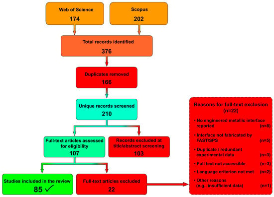
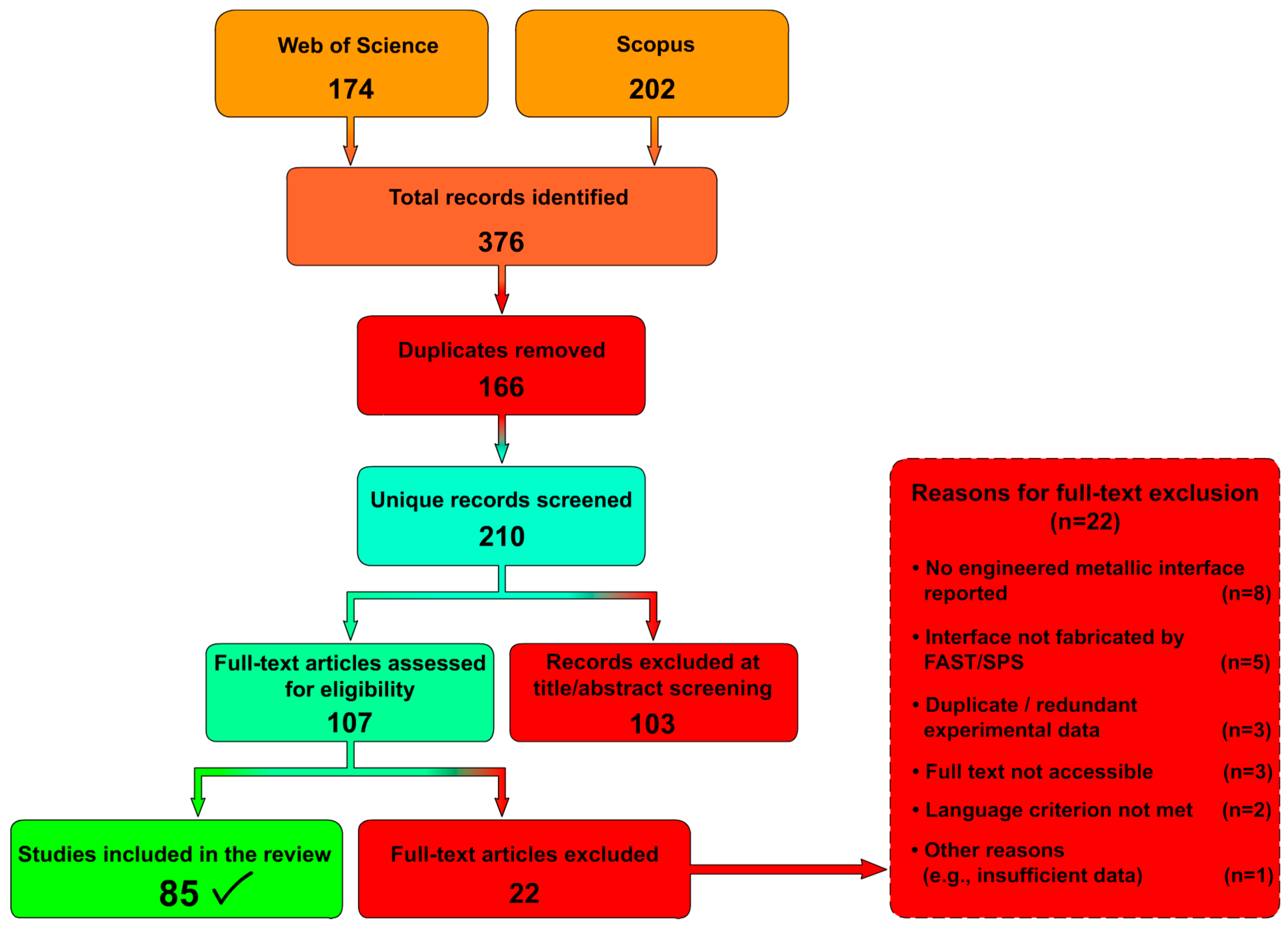
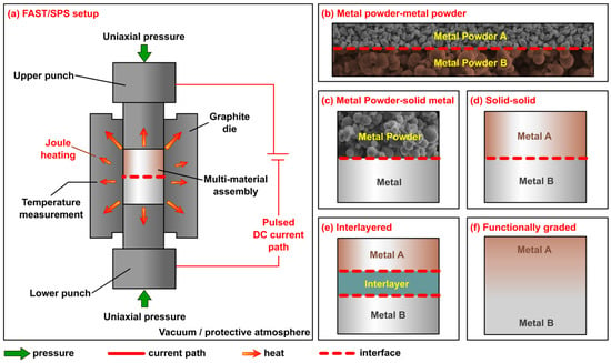
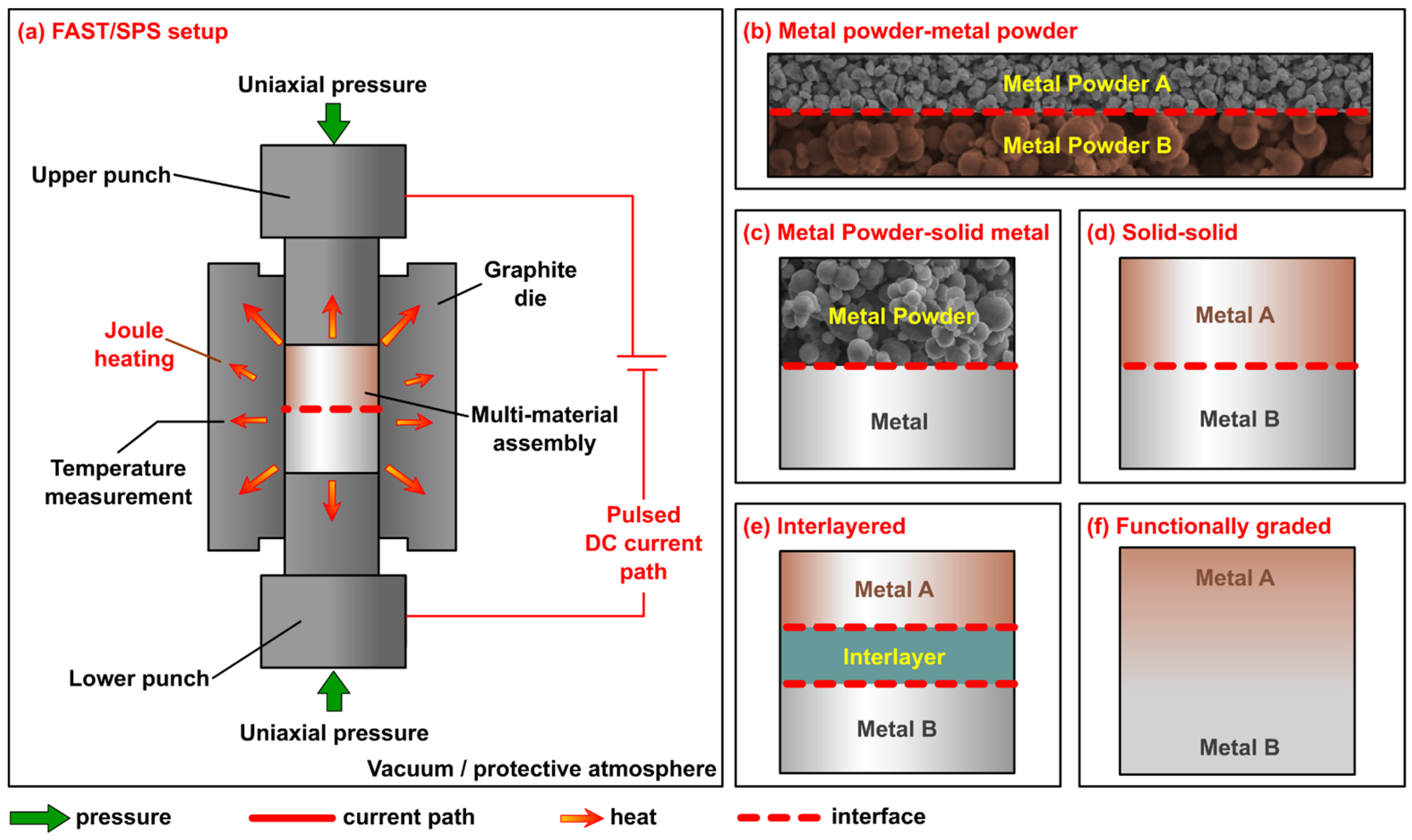
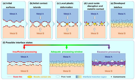
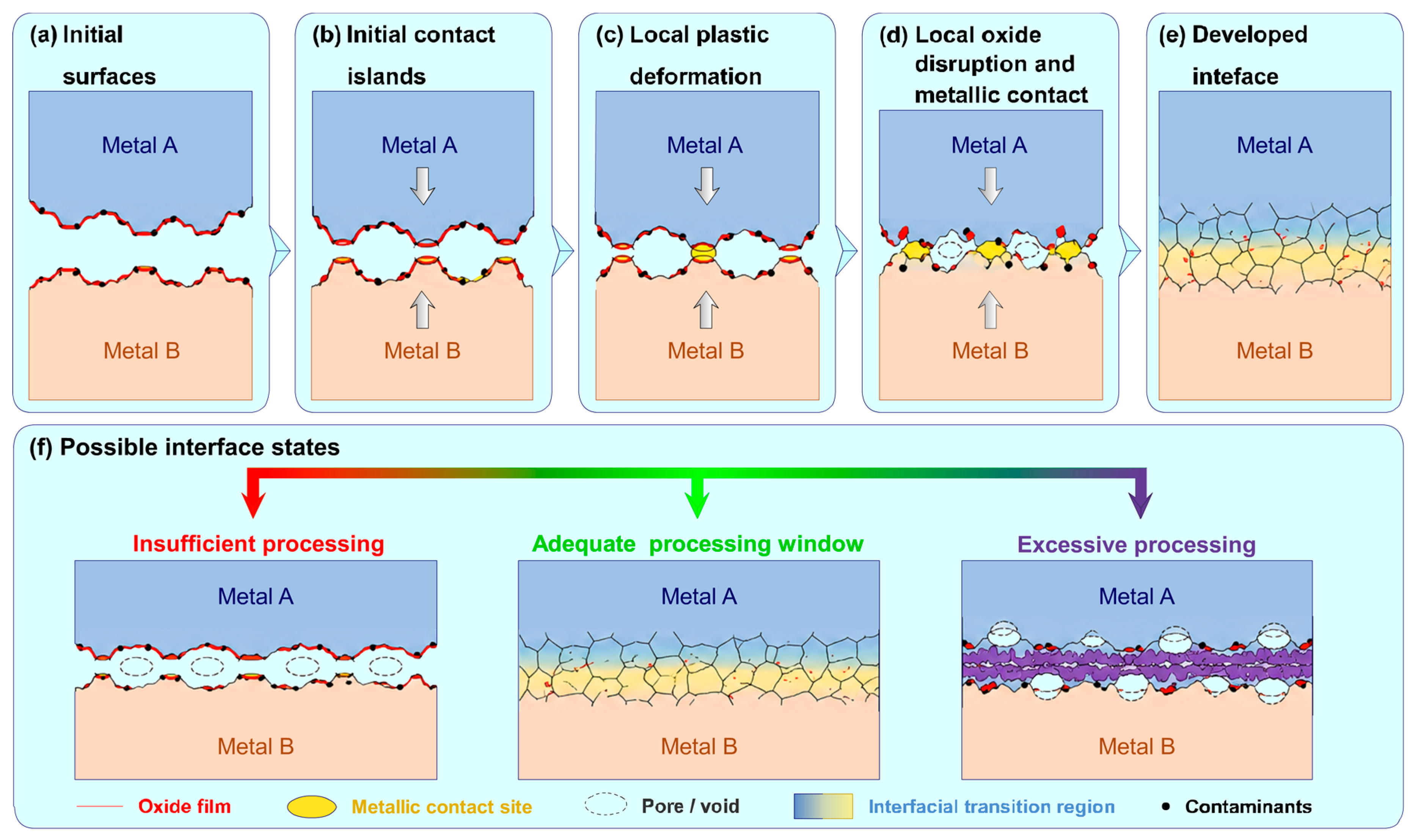
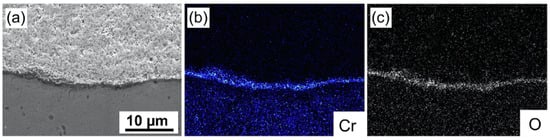
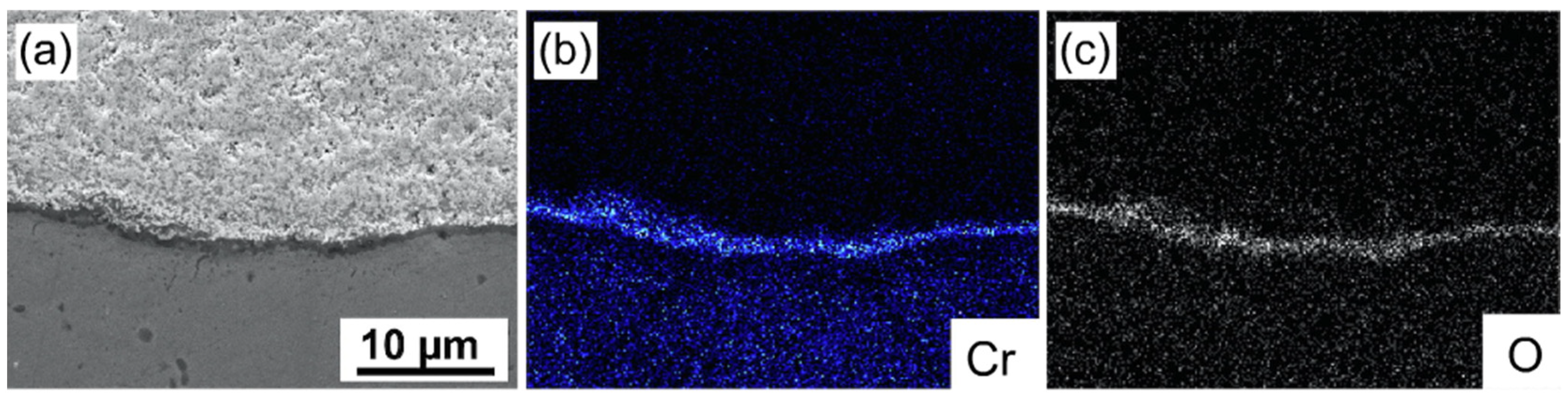
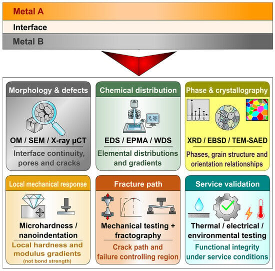
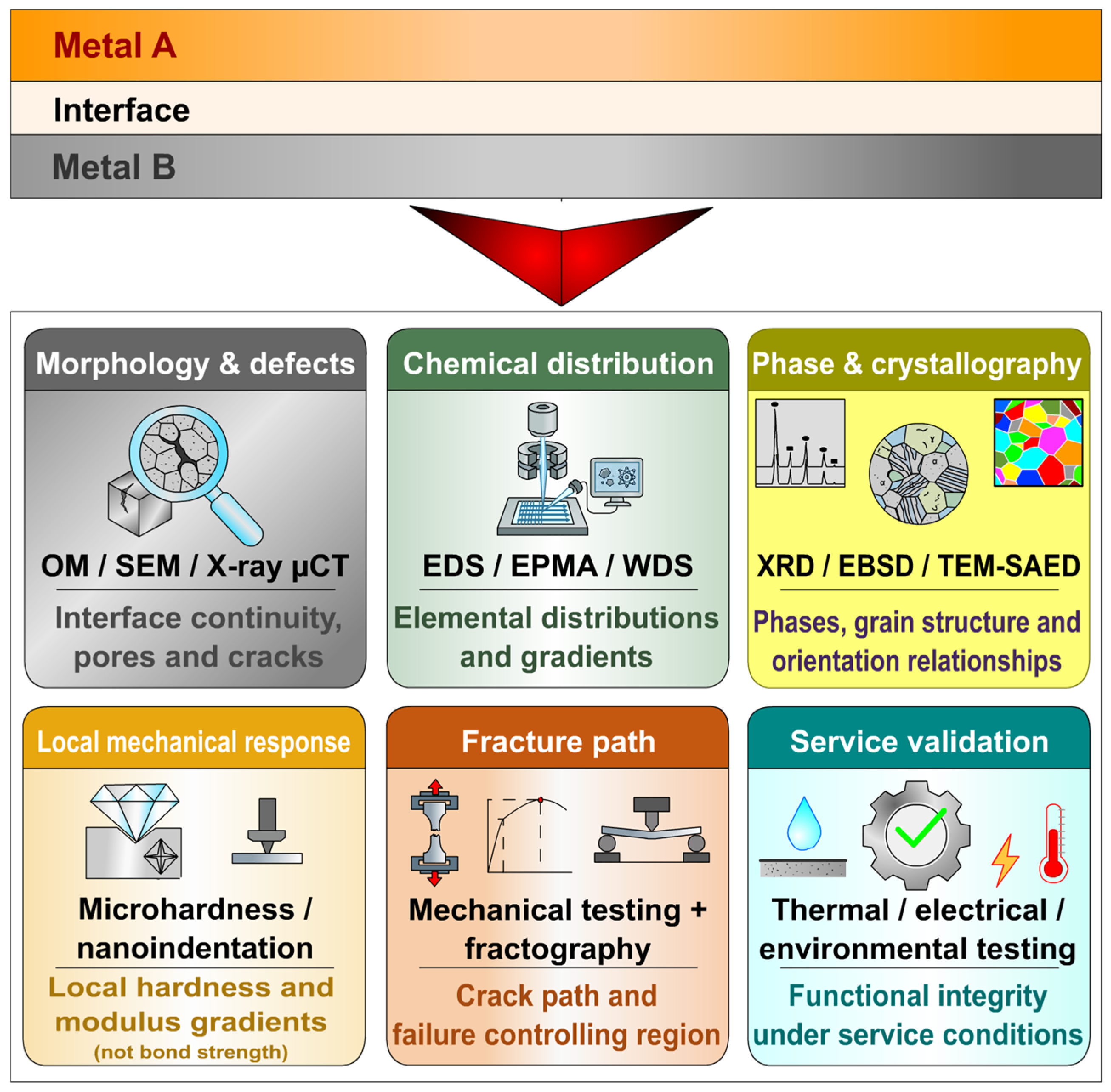
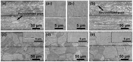
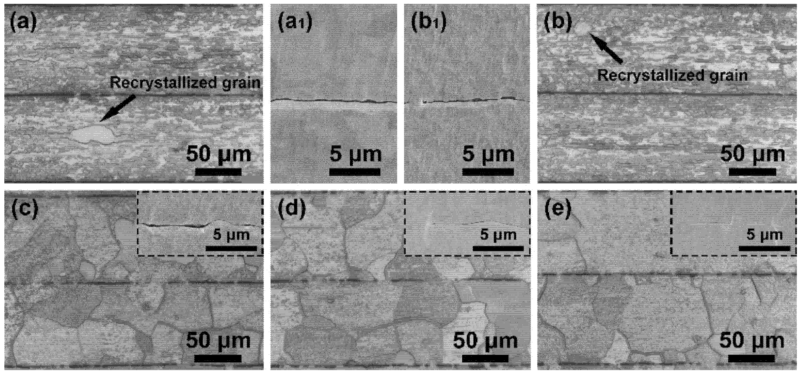
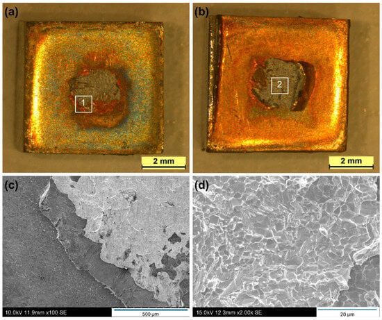
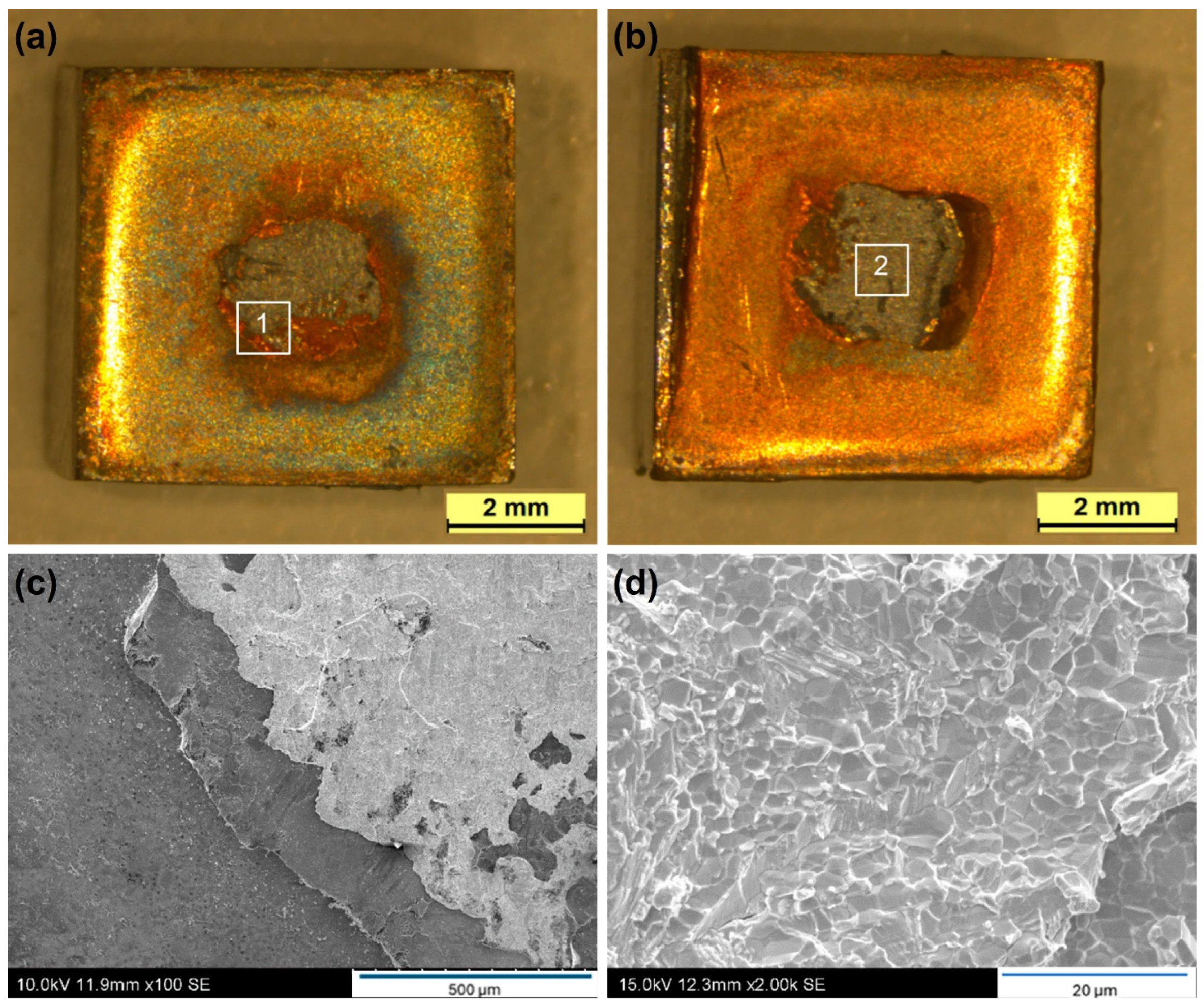
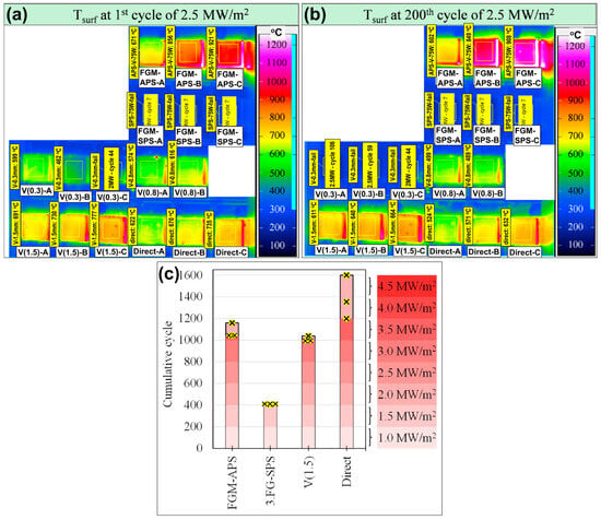
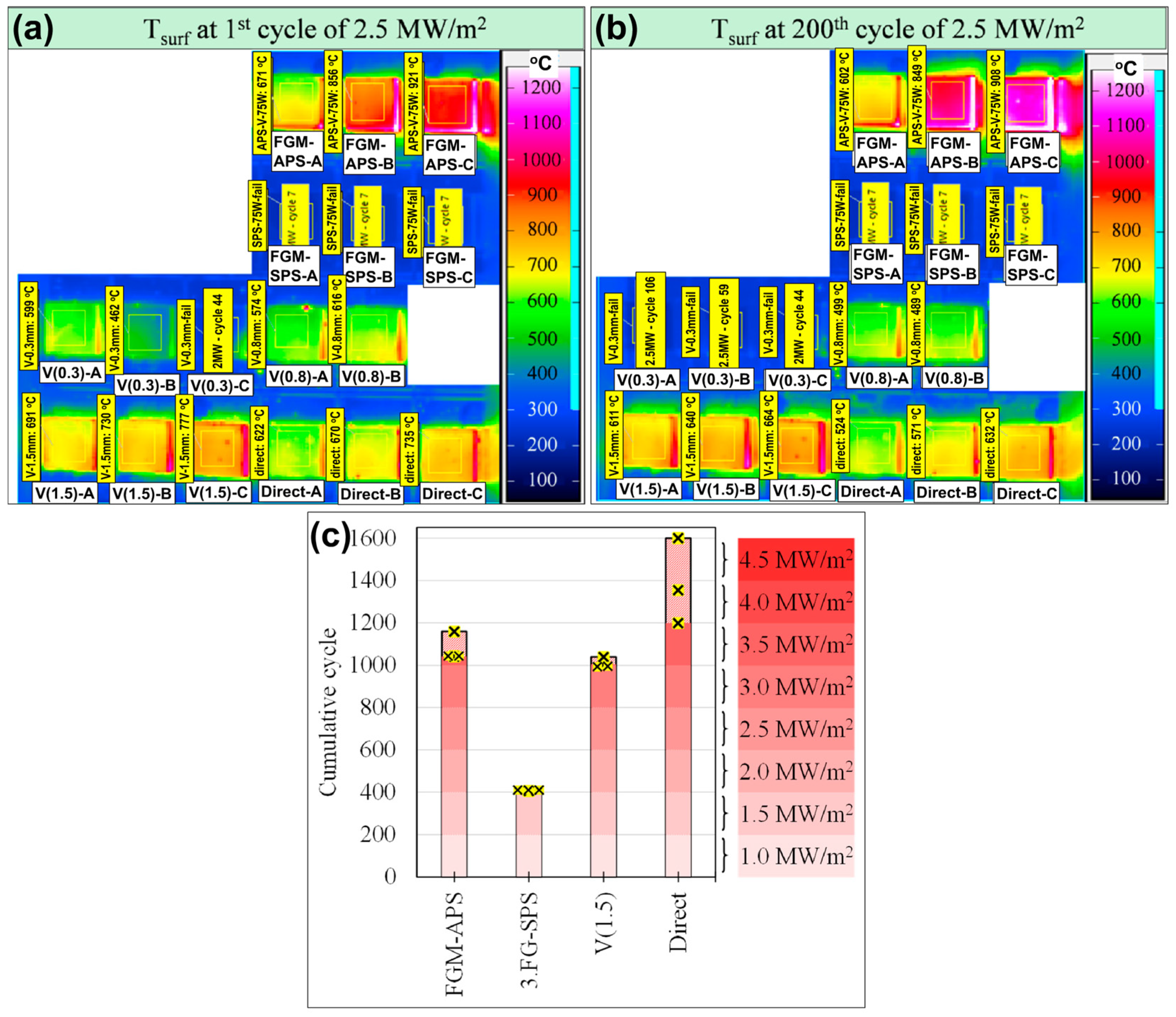
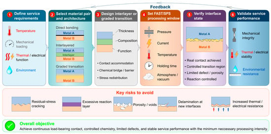
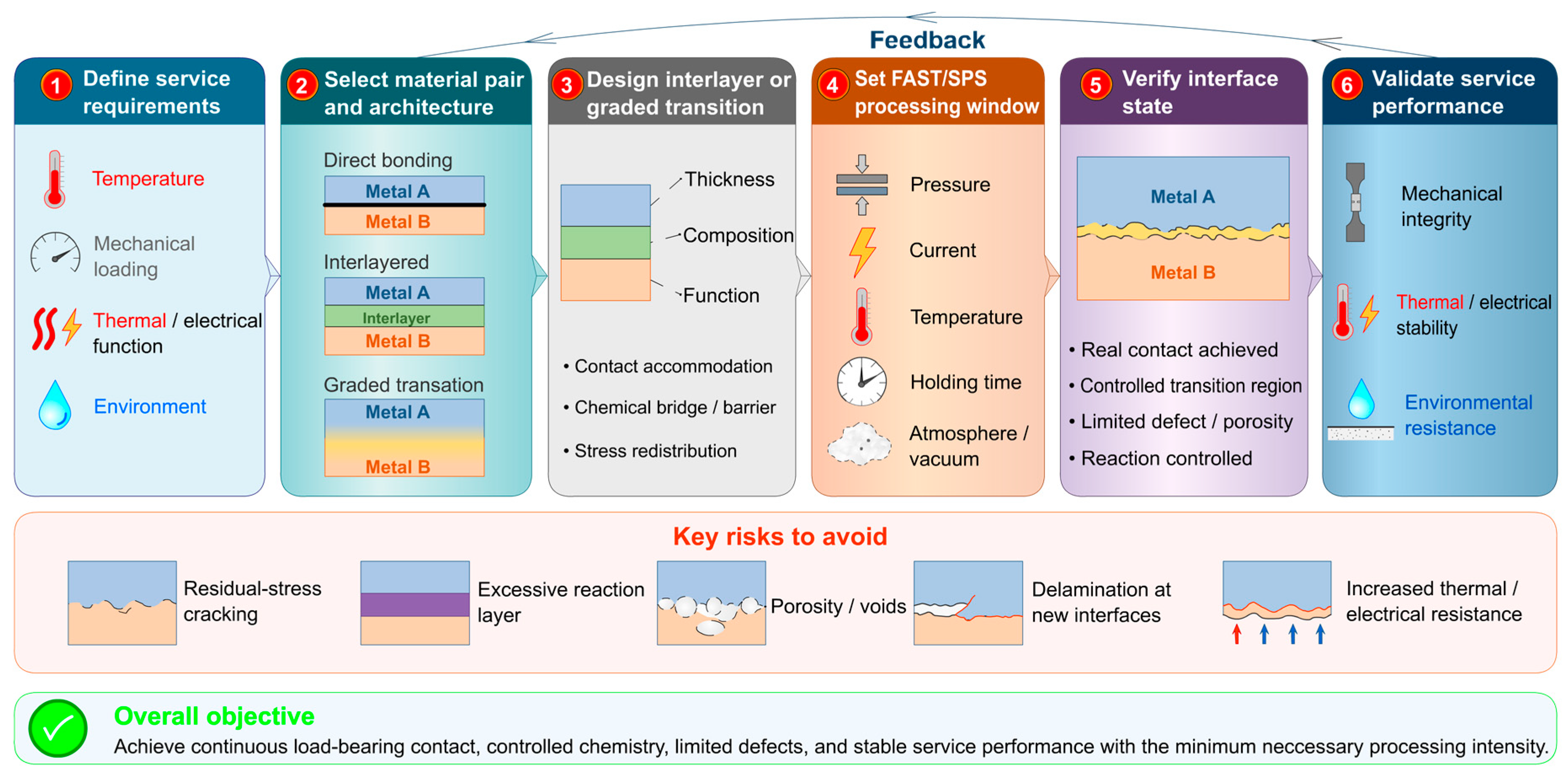

Disclaimer/Publisher’s Note: The statements, opinions and data contained in all publications are solely those of the individual author(s) and contributor(s) and not of MDPI and/or the editor(s). MDPI and/or the editor(s) disclaim responsibility for any injury to people or property resulting from any ideas, methods, instructions or products referred to in the content. |
© 2026 by the author. Licensee MDPI, Basel, Switzerland. This article is an open access article distributed under the terms and conditions of the Creative Commons Attribution (CC BY) license.