


Abstract
Internal cracks during slab bending and straightening are continuous-casting defects. Existing caster curves rely on plastic deformation, while curvature variation is concentrated within short sections, causing excessive strain rates and increasing the risk of internal straightening cracks. This study proposes a novel method for slab straightening through creep deformation and develops a curve for an R9300 caster by connecting cubic transition curves with cycloidal main segments. High-temperature tensile and constant-stress creep tests of Q345C steel were combined with transient thermal simulation and geometric strain-rate calculations. Under constraints on caster height, minimum curvature radius, and steady-state creep rate, the optimized parameters were a = 2600 mm and t = 3.6 rad. The curve eliminates the circular-arc section and ensures continuous position, tangent, and curvature. Its bending and straightening sections are each 9379 mm long, increases of 8349 and 7859 mm, respectively, while caster height increases by only 0.47 m. At the internal 1200 °C isotherm, the maximum strain rates are and , reductions of 82.2% and 81.1% relative to the conventional caster. Both remain below the steady-state creep rate of under ±10% secondary-cooling and ±10 °C casting-temperature fluctuations. The curve alleviates deformation concentration and enables the slab region at 1200 °C and above to bend and straighten through creep deformation.
1. Introduction
Continuous casting offers high production efficiency, high metallic yield, low energy consumption, and a high degree of process continuity, and has therefore become a core process in modern steelmaking [1,2]. During slab continuous casting, the strand is generally bent and straightened before complete internal solidification. As the curvature of the caster changes, longitudinal tensile and compressive deformation develops at different positions through the strand thickness, with the solidification front within the high-temperature solidified shell being particularly sensitive to tensile deformation. When the stress or strain induced by bending and straightening exceeds the corresponding critical value of the material, internal cracks may initiate and subsequently propagate [3,4,5]. Recent studies have investigated the formation of internal cracks in slabs from the perspectives of crack-sensitive regions, high-temperature ductility, and stress–strain evolution [6,7,8,9]. Fix et al., Pineda Huitron et al., Comineli et al., and Wang et al. further examined the high-temperature ductility and crack susceptibility of continuously cast strands with respect to steel-grade differences, secondary-cooling conditions, alloying elements, cooling rates, and nozzle arrangements [10,11,12,13]. Their results indicate that internal cracking is governed by the combined effects of the high-temperature deformation capacity of the material, the thermal history of the strand, and the imposed mechanical deformation. Steel grade and cooling conditions determine the thermal state and deformation tolerance of the strand, whereas the caster curve controls the distribution of bending and straightening deformation along the casting direction. Therefore, reducing abrupt changes in caster curvature, lowering local peak strain rates, and suppressing the concentrated accumulation of tensile deformation at the solidification front are important for reducing the risk of internal cracking during bending and straightening.
Bending and straightening technology for continuous casters has evolved from single-point and multi-point straightening to progressive and continuous straightening. Early single-point straightening concentrated the total straightening deformation at one location, resulting in relatively high local strain and instantaneous strain rate [14,15]. Multi-point straightening gradually changes the strand curvature through multiple roll pairs, thereby distributing the total deformation to some extent; however, roll-line curves composed of circular arcs with different radii still exhibit curvature discontinuities at their junctions [16,17]. Subsequently developed progressive and continuous straightening technologies arrange the rolls along prescribed curves, allowing the strand curvature to vary gradually along the casting direction and improving the load distribution among the straightening rolls [18,19]. On this basis, cubic polynomial curves, optimized continuous straightening curves, and involute–polynomial composite curves have been proposed to improve tangent and curvature continuity at the junctions between the bending segment, basic circular-arc segment, and straightening segment [20,21,22,23,24].
Although these caster curves have continuously evolved toward greater smoothness and continuity, their bending and straightening processes are still primarily based on plastic deformation. When the local stress reaches the high-temperature yield condition, the strand undergoes permanent curvature change through plastic deformation, thereby progressively completing the bending and straightening processes. The principal difference among single-point, multi-point, and continuous bending and straightening technologies lies in the spatial distribution of plastic deformation, rather than in the fundamental deformation mechanism. For a high-temperature strand, localized plastic deformation or an excessively high deformation rate may still impose substantial tensile deformation on crack-sensitive regions, thereby increasing the likelihood of internal cracks induced by bending and straightening.
Moreover, most conventional continuous bending and straightening caster curves retain a relatively long basic circular-arc segment. Within this segment, the strand curvature remains constant and no further bending or straightening deformation occurs, whereas the total curvature change is still concentrated within comparatively short bending and straightening segments. Consequently, although existing curves improve geometric continuity at segment junctions, the full caster path is not effectively utilized to distribute bending and straightening deformation. Eliminating the basic circular-arc segment and continuously distributing deformation over a longer caster path can extend the effective deformation time and reduce the temporal rate of curvature change, thereby creating the conditions required to replace the conventional plastic-deformation-based bending and straightening mechanism.
During continuous casting, the strand remains at high temperature for an extended period. Once the temperature reaches a sufficiently high level, irreversible deformation develops with time even when the applied stress remains below the corresponding yield strength and within the nominally elastic stress range; this phenomenon is referred to as high-temperature creep [25]. In conventional high-temperature service applications, creep is generally regarded as an adverse phenomenon that causes sustained deformation, damage accumulation, and eventual failure. Previous studies have therefore mainly focused on the creep behavior and microstructural evolution of various high-temperature materials [26,27,28,29,30]. However, during bending and straightening, a continuously cast strand is simultaneously subjected to high temperature and sustained loading, and its high-temperature creep deformation can contribute to the required permanent deformation. If the macroscopic strain rate in the crack-sensitive region is maintained below the corresponding steady-state creep rate during caster-curve design, bending and straightening can be completed progressively by creep rather than plastic deformation. In this manner, high-temperature creep, which is normally considered detrimental, can be utilized as a beneficial deformation mechanism for strand bending and straightening.
Zhang and Guo first proposed a creep-straightening method for Q345C steel strands by extending the straightening region and reducing the macroscopic strain rate below the steady-state creep rate [31]. Sui et al. subsequently measured the high-temperature tensile creep behavior of low-alloy steel and further applied the creep concept to a complete continuous bending and straightening curve for an R9300 caster [32,33]. These studies demonstrated the feasibility of using material creep capacity in caster-curve design.
However, the reported designs were mainly constructed for specific caster layouts, while a parameterized framework that links curve geometry, equipment constraints, thermal-field response, and material creep-rate thresholds remains insufficiently developed. To address this issue, the present study uses an industrial R9300 caster as a representative design case and proposes a parameterized continuous bending and straightening curve composed of cubic transition curves smoothly connected to cycloidal main segments. The proposed curve distributes the curvature variation over a longer caster path while ensuring positional, tangential, and curvature continuity at adjacent segment junctions. The cycloid modulus a and connection-angle parameter t are selected as independent design variables, and computational models are established for caster height and maximum macroscopic strain rate. The curve parameters are then screened and optimized under the combined constraints of available equipment space, minimum curvature radius, and measured steady-state creep rate.
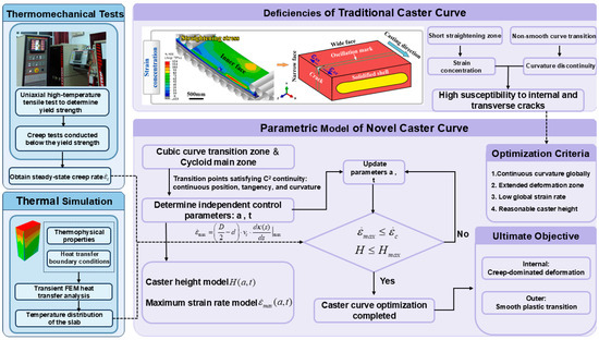
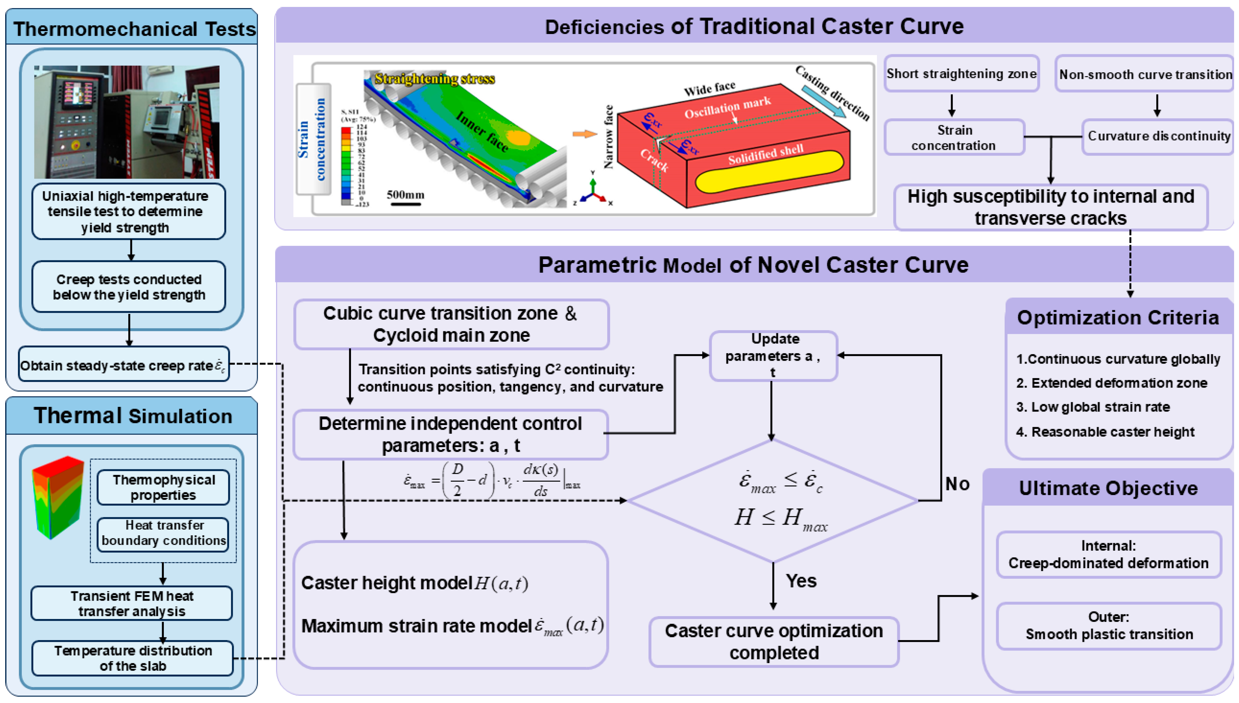
The overall research procedure is illustrated in Figure 1. High-temperature tensile and constant-stress creep tests are first conducted to determine the yield strength and steady-state creep rate of Q345C steel. A transient slice-based thermal model is then used to determine the position of the selected isotherm within the strand, which is combined with the geometric strain-rate model for parameter optimization. The optimized curve is quantitatively compared with the conventional R9300 caster, and its robustness is further evaluated through sensitivity analyses of secondary-cooling intensity, casting-temperature fluctuation, and measured creep-rate uncertainty. The proposed parameterized modeling and constraint-based screening strategy provides a systematic framework for creep-assisted caster-curve optimization.
Figure 1.
Flowchart of caster-curve design optimization based on high-temperature creep.
2. Materials and Methods
2.1. Material and High-Temperature Mechanical Tests
This study focuses on Q345C low-alloy steel; its core chemical composition is listed in Table 1. To precisely determine the safe threshold for high-temperature deformation under continuous-casting conditions, high-temperature tensile and constant-stress creep experiments were specifically conducted on actual continuous-casting slabs in this research.
Table 1.
Chemical composition of selected elements in Q345C steel (wt.%).
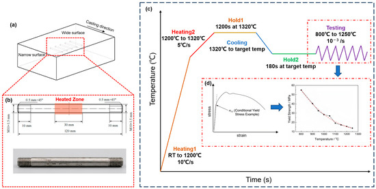
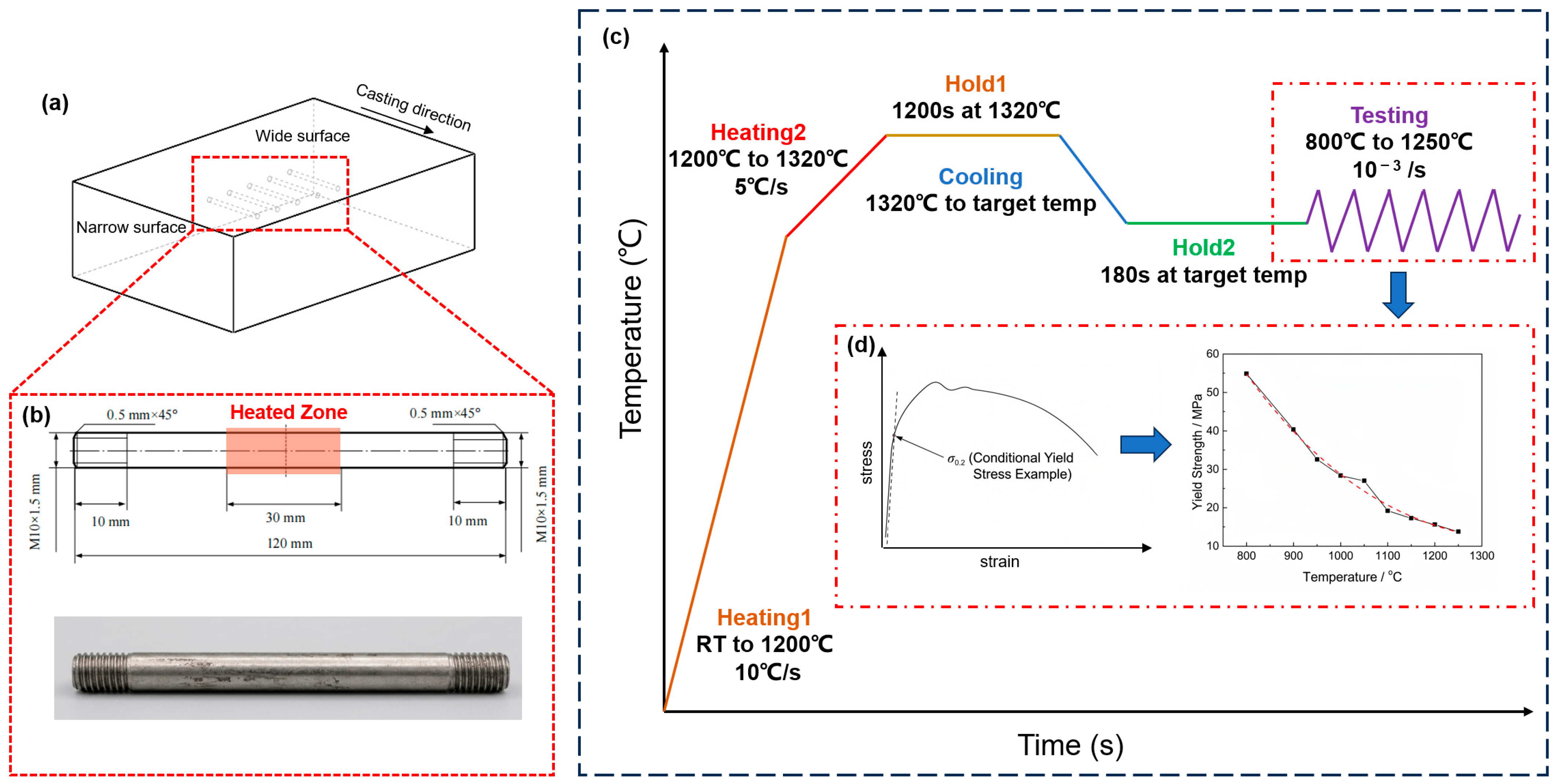
Figure 2 details the sampling locations and testing specifications of these experiments. Specimens were extracted along the casting direction of an actual continuous-casting slab and machined into standard testing geometries. Subsequently, utilizing a Gleeble-3800 thermomechanical simulator (Dynamic Systems Inc., Poestenkill, NY, USA), high-temperature tensile and constant-stress creep tests were executed, strictly simulating the actual thermal history experienced during the continuous-casting process. Based on the high-temperature tensile test curves, the yield stress of the material was calculated and acquired strictly according to the 0.2% offset strain method. Consequently, the evolution law of the yield stress for this steel grade across a broad temperature range of 800~1250 °C was obtained.
Figure 2.
High-temperature mechanical testing: (a) slab sampling locations; (b) specimen geometries; (c) thermomechanical testing conditions; (d) 0.2% offset yield stress.
During the continuous-casting straightening stage, the surface and internal temperatures of the slab typically remain at high levels often exceeding 1000 °C. According to mechanical property tests, the high-temperature ductility zone of Q345C steel lies between 1100 °C and 1200 °C. Therefore, the constant-stress creep tensile tests in this study specifically focused on this critical temperature range. After the specimens reached the prescribed temperature and were held for thermal equilibrium, a constant tensile stress was applied. To ensure experimental repeatability, three independent tests were conducted under each temperature and stress condition. The results obtained under identical conditions showed good consistency, and the averaged values of the three tests were used in the subsequent analysis.
2.2. Reference Caster and Operating Conditions
The reference object in this study was an industrial R9300 vertical-arc slab continuous caster(Angang Steel Company Limited, Anshan, Liaoning, China) with five-point bending and five-point straightening. The slab section was 1000 mm × 230 mm, and the casting speed was 1.5 m/min. The main operating parameters and geometric layout of the reference R9300 caster are summarized in Table 2.
Table 2.
Main operating and geometric parameters of the R9300 continuous caster.
2.3. Transient Thermal Model and Boundary Conditions
2.3.1. Thin-Slice Thermal Model
A transient two-dimensional heat-transfer model was established to determine the temperature distribution and the internal high-temperature region of the slab.
Under steady-state casting conditions, the casting speed and cooling parameters were assumed to be constant. Therefore, heat transfer along the casting direction was neglected, and the thin-slice method was adopted. In this method, the slab cross-section is treated as a moving slice passing successively through the mold and secondary-cooling zones. The relationship between the transient calculation time and the distance from the meniscus is expressed as:
where z is the distance from the meniscus in mm, is the casting speed in mm/s, and t is the transient calculation time in s.
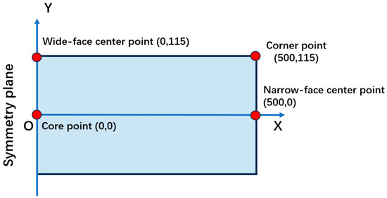
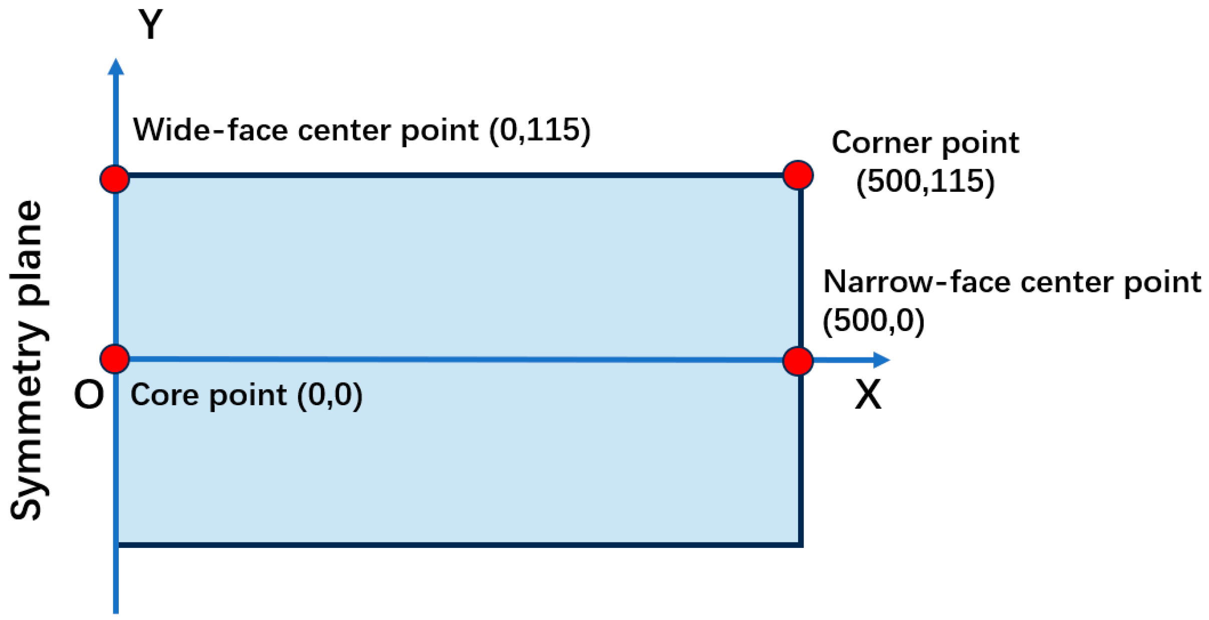
Considering the symmetry of the slab cross-section and cooling boundary conditions, a half cross-section model with a size of 500 mm × 230 mm was established in the present study in Figure 3. The slab core, wide-face center, narrow-face center, and corner were located at (0,0), (0,115), (500,0), and (500,115), respectively. The transient heat-transfer model was solved using the implicit solver in Abaqus/Standard 2022. The slab cross-section was discretized using DC2D4 elements.
Figure 3.
Schematic diagram of the half cross-section thin-slice thermal model and the four characteristic temperature monitoring points.
2.3.2. Governing Equation and Thermophysical Parameters
The governing equation of transient heat conduction in the two-dimensional cross-section can be written as:
where T is the temperature, t is the time, is the density, is the specific heat, is the thermal conductivity, and represents the equivalent heat source or equivalent heat-capacity treatment associated with latent heat release during solidification. The temperature-dependent thermophysical parameters used in the present model are listed in Table 3.
Table 3.
Thermophysical parameters used in the transient heat-transfer model.
2.3.3. Mold and Secondary-Cooling Boundary Conditions
The heat flux in the mold was described using an empirical time-dependent relation:
where q is the mold heat flux and L is the mold length. The value of q was converted according to the unit system used in the finite element model.
In the secondary-cooling zone, the integrated surface heat flux was expressed as:
where is the integrated heat flux on the slab surface, T is the slab surface temperature, is the cooling-water temperature, and is the equivalent heat-transfer coefficient. The equivalent heat-transfer coefficient was calculated from the cooling-water flux as:
where is the cooling-water flux. The cooling-water distribution of the secondary-cooling zone was assigned according to the cooling-loop arrangement of the R9300 caster reported in Table 4 and Table 5.
Table 4.
Segment lengths of the secondary-cooling zones in the R9300 caster.
Table 5.
Water flow distribution in the secondary-cooling loops of the R9300 caster.
The heat flux density in the air-cooling zone is given by the following formulae:
where is the convective heat-transfer coefficient in , is the surface temperature of the cast slab in , is the air temperature in , is the Stefan–Boltzmann constant in , and is the surface emissivity.
2.3.4. Verification of the Transient Thermal Model
To verify the mesh independence of the transient thermal model, four mesh sizes of 15, 10, 5, and 2.5 mm were examined. The 2.5 mm mesh was used as the reference. Four characteristic points, namely the slab core, narrow-face center, wide-face center, and corner, were selected for temperature comparison. In addition, the depth of the 1200 °C isotherm was extracted because it is directly used in the subsequent strain-rate calculation.
The quantitative results are summarized in Table 6. For the 5 mm mesh, the final maximum temperature deviation is only 0.27 °C, and the maximum, mean, and final deviations of the 1200 °C isotherm depth are 0.49, 0.03, and 0.03 mm, respectively. Therefore, the 5 mm mesh was adopted for the subsequent thermal analysis considering both accuracy and computational cost.
Table 6.
Mesh-independence summary relative to the 2.5 mm mesh.
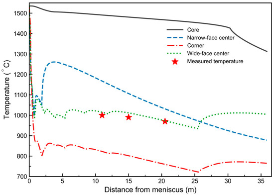
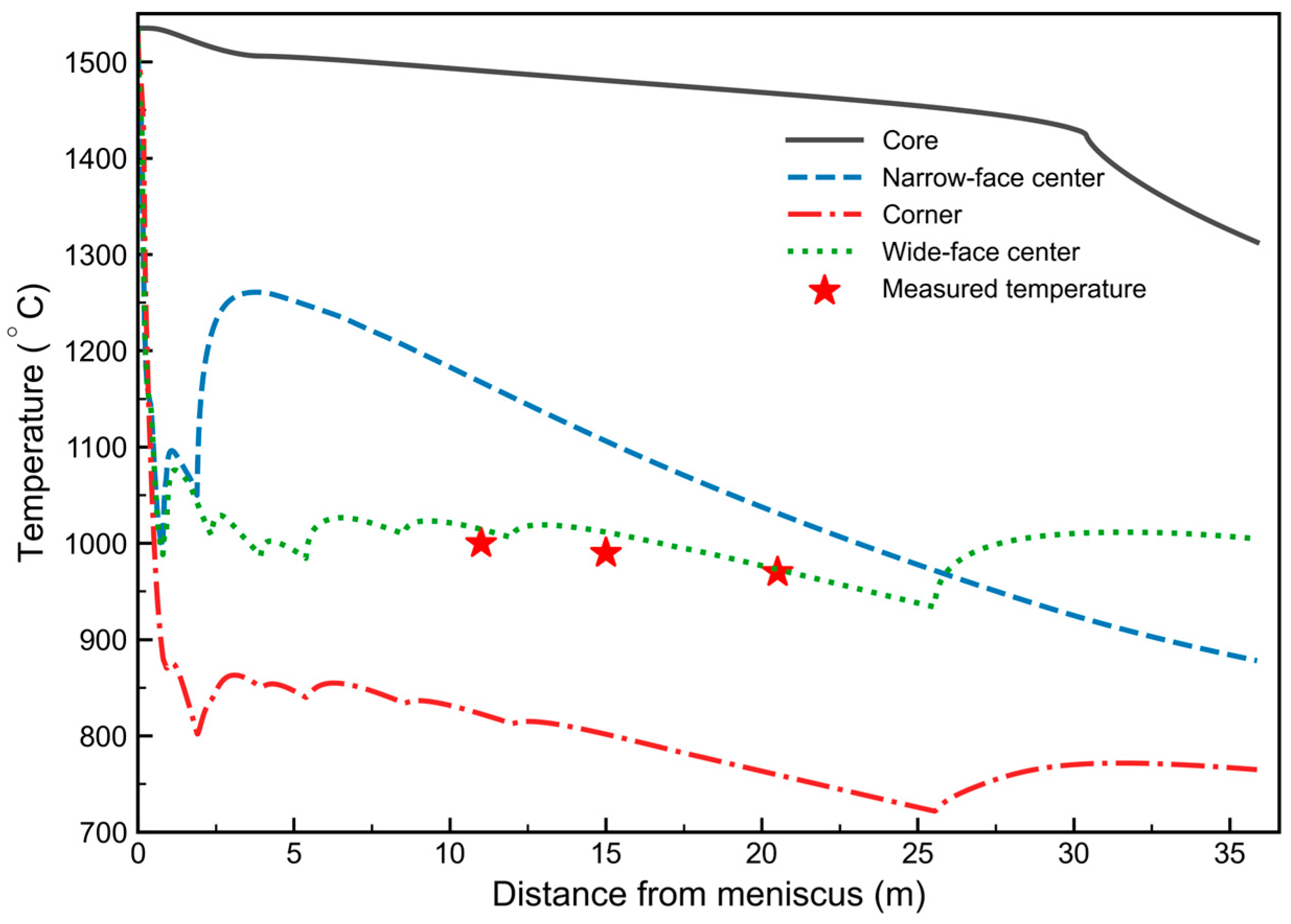
Based on the mesh-independent 5 mm model, the simulated temperature evolution at four characteristic positions was obtained. The calculated wide-face-center surface temperatures were then compared with the measured surface temperatures in the secondary-cooling zone. As shown in Figure 4, the measured temperatures follow the same decreasing trend as the simulated wide-face-center temperature curve, indicating that the transient thermal model can reasonably reproduce the surface cooling behavior of the slab.
Figure 4.
Simulated temperature evolution at four characteristic positions and comparison with measured wide-surface temperatures.
2.4. Geometric Configuration Theory of Cycloid Caster Curve
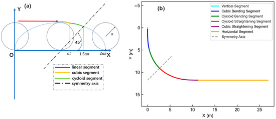
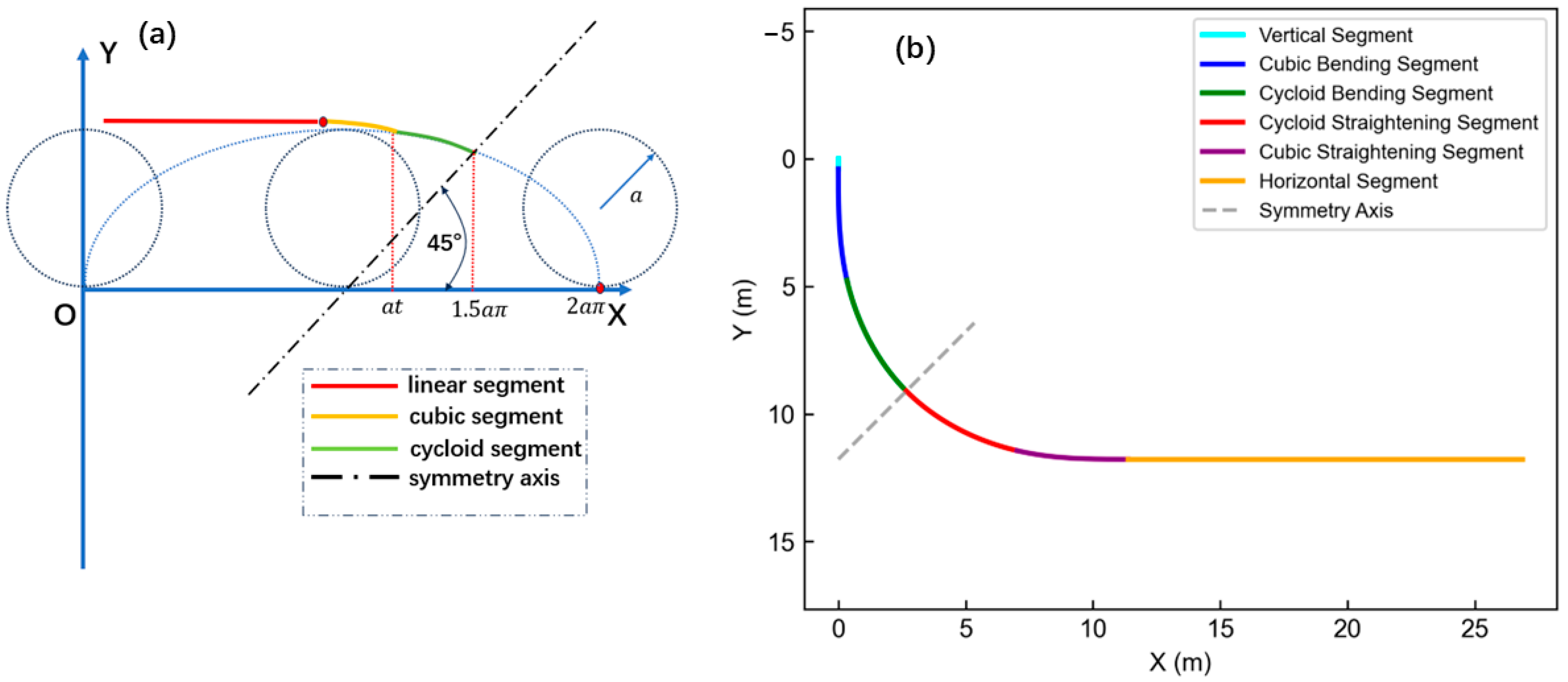
To overcome the curvature discontinuities inherent in traditional multi-point casters, this study proposes a continuous caster-curve design strategy by combining cycloid segments with cubic transition curves. As illustrated in Figure 5a, the local geometric construction of the proposed caster curve is governed by two primary parameters. The cycloid modulus a, corresponding to the radius of the generating circle, controls the overall spatial scale of the curve. The connection-angle parameter t represents the cycloidal parameter value at the junction between the cubic transition segment and the cycloid main segment, thereby determining the connection location and the extent of the transition region. Accordingly, a and t are selected as the two independent geometric parameters of the caster curve. Based on this local geometric construction, the complete caster curve is generated through coordinate transformation, rotation, and symmetry operations, as shown in Figure 5b. The complete curve consists sequentially of a vertical segment, a cubic bending transition segment, a cycloid bending segment, a cycloid straightening segment, a cubic straightening transition segment, and a horizontal segment. This global coordinate system provides a unified reference for formulating the piecewise parametric equations in Section 2.4.1, Section 2.4.2, Section 2.4.3 and Section 2.4.4.
Figure 5.
Construction principle and layout of the optimized caster curve: (a) cycloid interception and cubic transition; (b) coordinate system of the novel caster curve.
With a and t fixed, the auxiliary quantities m, r, h, and n are uniquely obtained from the boundary and continuity conditions. These quantities are dependent parameters introduced only to simplify the following piecewise equations:
The calculation formulas are given as:
With these auxiliary quantities defined, the parametric equations of the individual curve segments are formulated below.
2.4.1. Vertical Segment Equation
Given that the subsequent cubic curve inherently provides a highly smooth transition, only a minimal vertical segment length is required prior to bending.
where is the length of the vertical segment, mm.
2.4.2. Cubic Bending Segment Equation
This segment serves to satisfy the boundary conditions, facilitating a continuous curvature departure from the vertical direction (). By introducing the local parameter , the parametric expressions are formulated as:
In this domain, increases approximately linearly, whereas increases marginally following a cubic relationship to ensure a smooth initiation of bending.
2.4.3. Cycloid Bending Segment Equation
Serving as the primary geometrical body, this segment accommodates the main bending deformation and gravity drop. Utilizing the local parameter , the geometry is described by:
2.4.4. Straightening Segment Equation
Representing the kinematic reversal of the bending process, the straightening curve is derived via a mirror transformation of the bending segment with respect to a defined symmetry axis. This symmetric configuration guarantees that the exit tangent seamlessly transitions to a horizontal state, concurrently yielding an antisymmetric strain-rate distribution relative to the bending zone. Define the symmetry center at the endpoint of the bending segment ():
For any point on the bending segment, its corresponding point on the straightening segment is symmetrical about the line :
2.5. Multi-Objective Optimization Model of Cycloid Caster Curve
Since the proposed curve cancels the traditional basic arc segment, the deformation constraint is imposed on the minimum curvature radius of the optimized curve. The minimum curvature radius occurs at the connection point between the bending and straightening segments and is required to satisfy the empirical radius condition for slab casting:
where is the minimum curvature radius of the optimized caster curve, D is the slab thickness, and is the allowable surface strain of the slab, which is usually taken as 1.5–2.0% for carbon and low-alloy steels [34].
The total caster height, , and the maximum strain rate, , are formulated as bivariate functions of the independent parameters and .
The total height, , corresponds to the y-coordinate at the exit of the straightening segment:
Substituting the geometric definitions, the final analytical expression for the height is derived as:
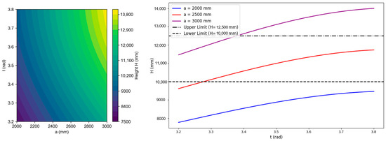
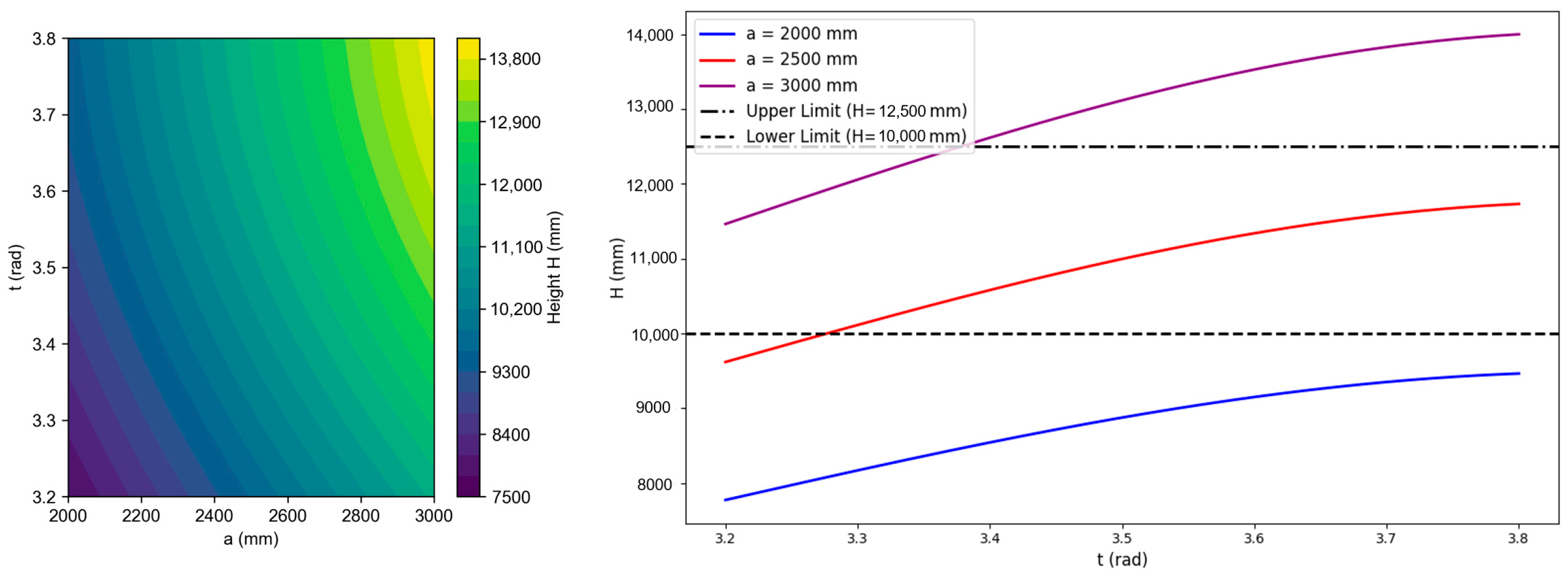
To ensure metallurgical quality while strictly controlling height, the reasonable height domain for the new caster curve is set between 10,000 and 12,500 mm.
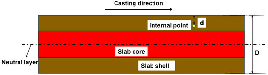
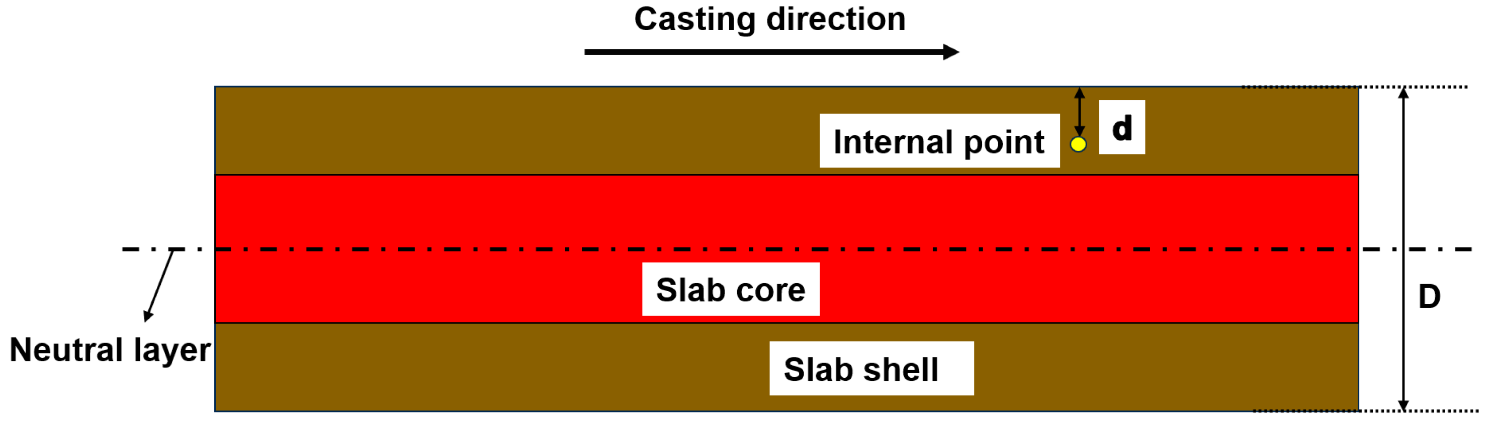
During continuous casting, the slab features a partially solidified liquid core, where the symmetry center along the thickness direction defines the neutral layer in Figure 6. The maximum strain rate at a given internal point is governed by the change rate of curvature along the casting direction:
where represents the total slab thickness, denotes the depth from the slab surface to the internal point of interest, is the curvature of the caster curve, and is the arc length along the caster curve.
Figure 6.
Cross-section of the continuous-casting slab.
For the cubic transition segment, the strain rate is calculated as:
where acts as a dimensionless correction coefficient, defined as:
Conversely, the strain rate within the primary cycloid segment is evaluated by:
Consequently, the global maximum strain rate across the entire continuous caster curve is determined by:
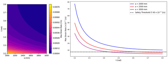
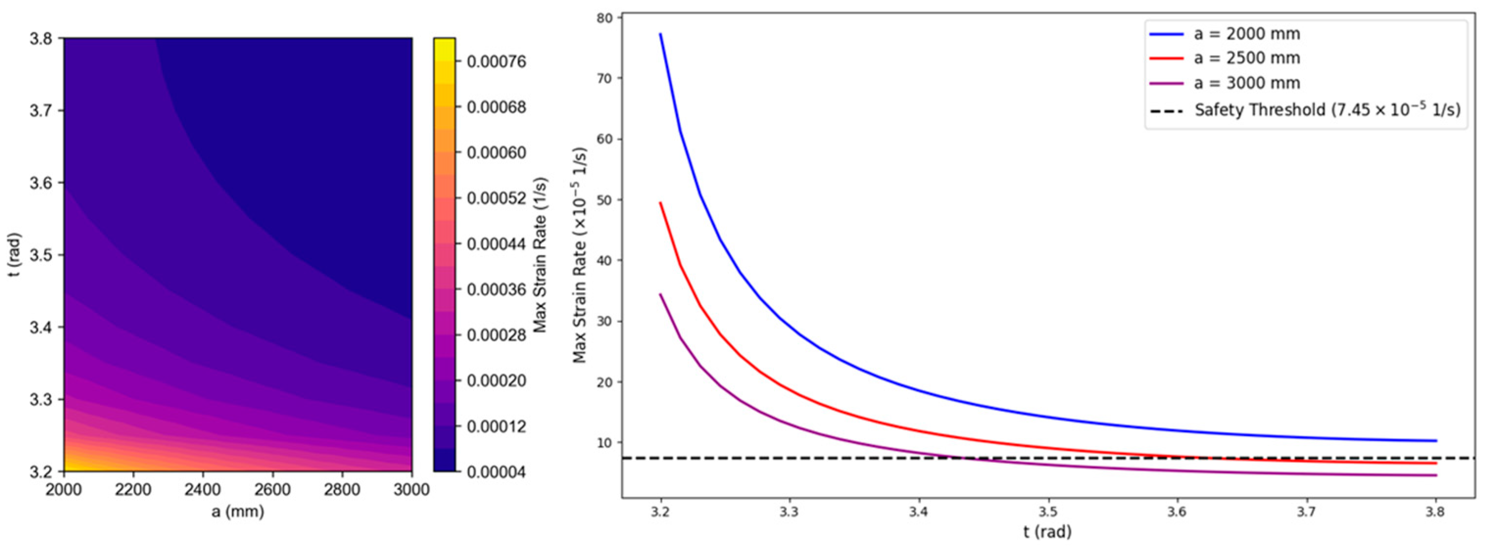
To ensure that the slab deforms predominantly via the high-temperature creep mechanism, must not exceed the material’s minimum steady-state creep strain rate, , functioning as a hard constraint:
Any combination of geometric parameters () that induces localized strain rates surpassing this critical threshold is deemed invalid, irrespective of any potential benefits in reducing the total caster height.
3. Results
3.1. High-Temperature Tensile and Creep Behavior
To isolate purely time-dependent creep strain from instantaneous plastic deformation, the applied constant tensile stresses were controlled slightly below the respective yield strengths (Table 7).
Table 7.
High-temperature creep tensile tests of Q345C steel.
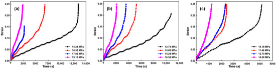
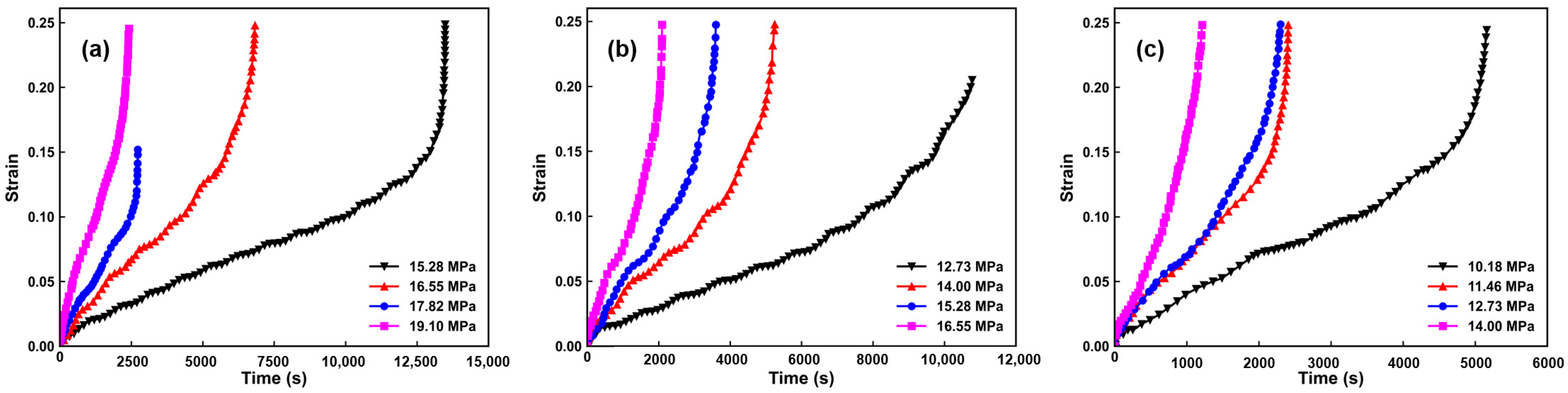
Figure 7 illustrates the creep strain–time curves of Q345C steel under various applied stresses at 1100 °C, 1150 °C, and 1200 °C. During data extraction, the instantaneous elastic strain upon initial loading was excluded, and recording commenced once the stress reached a steady state. The individual sub-figures reveal that under lower stresses, the steady-state creep stage is prolonged. Conversely, as the stress increases, the duration of the steady-state creep stage shortens progressively while the creep rate escalates rapidly, driving the material into the accelerated creep fracture stage earlier.
Figure 7.
Creep strain–time curves of Q345C steel under various stresses: (a) 1100 °C, (b) 1150 °C, (c) 1200 °C.
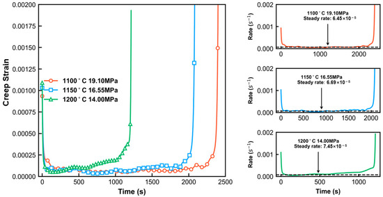
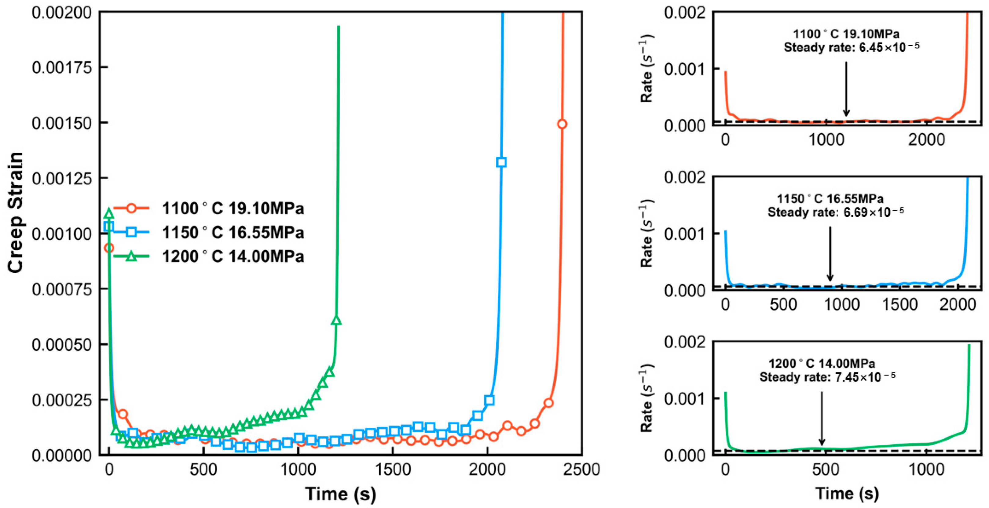
Under these conditions (19.10 MPa at 1100 °C, 16.55 MPa at 1150 °C, and 14.00 MPa at 1200 °C), the specimens exhibited significant pure creep deformation without plastic yielding. The resulting pure creep strain-rate–time curves are shown in Figure 8.
Figure 8.
Pure creep strain-rate curves of Q345C steel near yield strength (1100 °C, 1150 °C, 1200 °C).
Consequently, the steady-state creep strain rates of Q345C steel are obtained at 1100 °C, 1150 °C, and 1200 °C. These values are used as the creep-rate thresholds for the subsequent caster-curve optimization.
3.2. Effect of Geometric Parameters on Caster Height and Strain Rate
Numerical calculations were performed within the feasible design domain, and the effects of the cycloid modulus a and connection-angle parameter t on caster height and maximum strain rate are shown in Figure 9 and Figure 10.
Figure 9.
Effect of geometric parameters on total caster height.
Figure 10.
Effect of geometric parameters on maximum strain rate.
As shown in Figure 9, the total caster height increases mainly with the cycloid modulus a, while the connection-angle parameter t further modifies the height through the transition length. A larger a increases the spatial scale of the curve and may cause the caster height to exceed the allowable engineering range. In contrast, moderate values of a keep the curve within the prescribed height constraint.
As shown in Figure 10, the maximum strain rate decreases with increasing a and t. A larger a increases the characteristic curvature radius, whereas a larger t smooths the transition between the cubic and cycloidal segments. Conversely, smaller values of a or t lead to more rapid curvature variation and higher local strain-rate peaks. Therefore, the optimized parameter combination should be selected by simultaneously satisfying the caster-height constraint and the steady-state creep-rate constraint.
3.3. Optimized Cycloid Caster Curve
Based on the parameter effects shown in Figure 9 and Figure 10, the final curve parameters were selected by simultaneously considering the caster-height constraint, the minimum curvature-radius requirement, and the steady-state creep-rate threshold of Q345C steel. The optimized parameter combination was determined as:
This scheme geometrically eradicates all curvature mutation points. The specific analytical equations for the segments are:
4. Discussion
4.1. Thermal-Field Response and Process-Parameter Sensitivity of the Optimized Caster Curve
After the optimized caster curve was determined, the characteristic positions along the new caster layout were converted into casting times according to the casting speed and curve arc length. Because the creep tests demonstrated pronounced creep deformation of Q345C steel at 1200 °C, this isotherm was selected as the boundary of the internal high-temperature region.
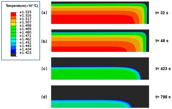
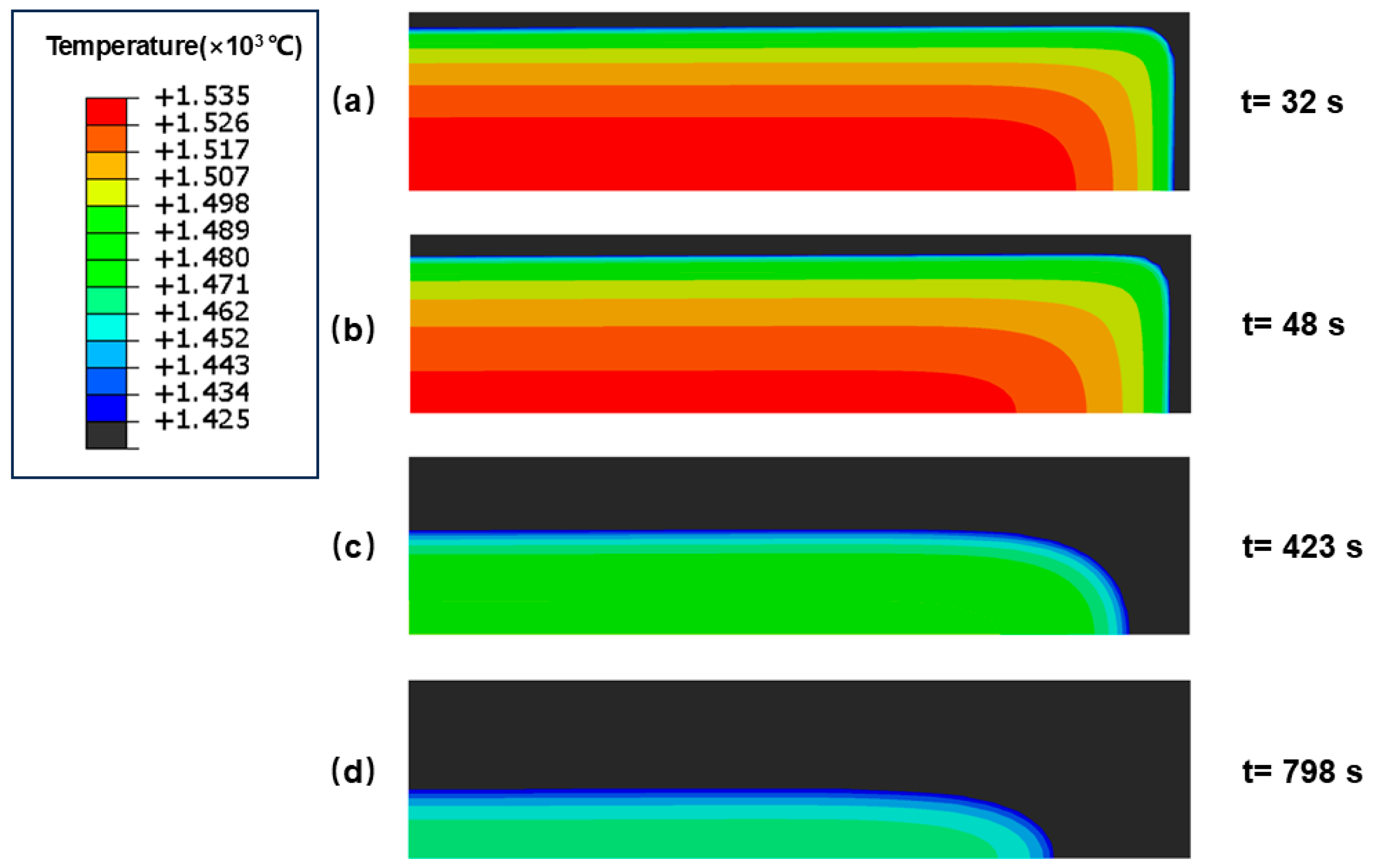
Figure 11 presents the simulated temperature contours of the slab cross-section at four representative casting times. The region below the solidus temperature of 1425 °C is shown in black, whereas the colored region represents the mushy or liquid zone above the solidus temperature. As casting proceeds, the solidified shell continuously thickens, while the corner region cools faster than the wide- and narrow-face centers because of heat extraction from two directions. At 423 s, corresponding to the completion of bending and the onset of straightening, a large high-temperature region remains inside the slab. Even at 798 s, when straightening is completed, the slab interior still retains a relatively high temperature.
Figure 11.
Temperature fields at different moments: (a) mold exit; (b) onset of bending; (c) completion of bending (onset of straightening); (d) completion of straightening.
As verified in Section 2.3.4, the transient thermal model reasonably reproduces the measured surface cooling behavior. Therefore, the calculated temperature field was used to determine the position of the internal 1200 °C isotherm, which was subsequently combined with the rate of curvature change along the optimized caster curve to evaluate the internal bending and straightening strain rates.
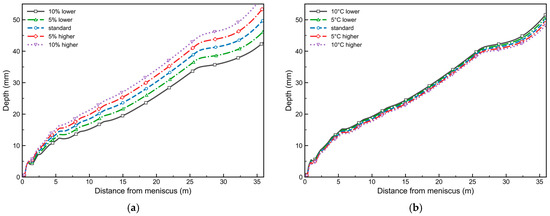
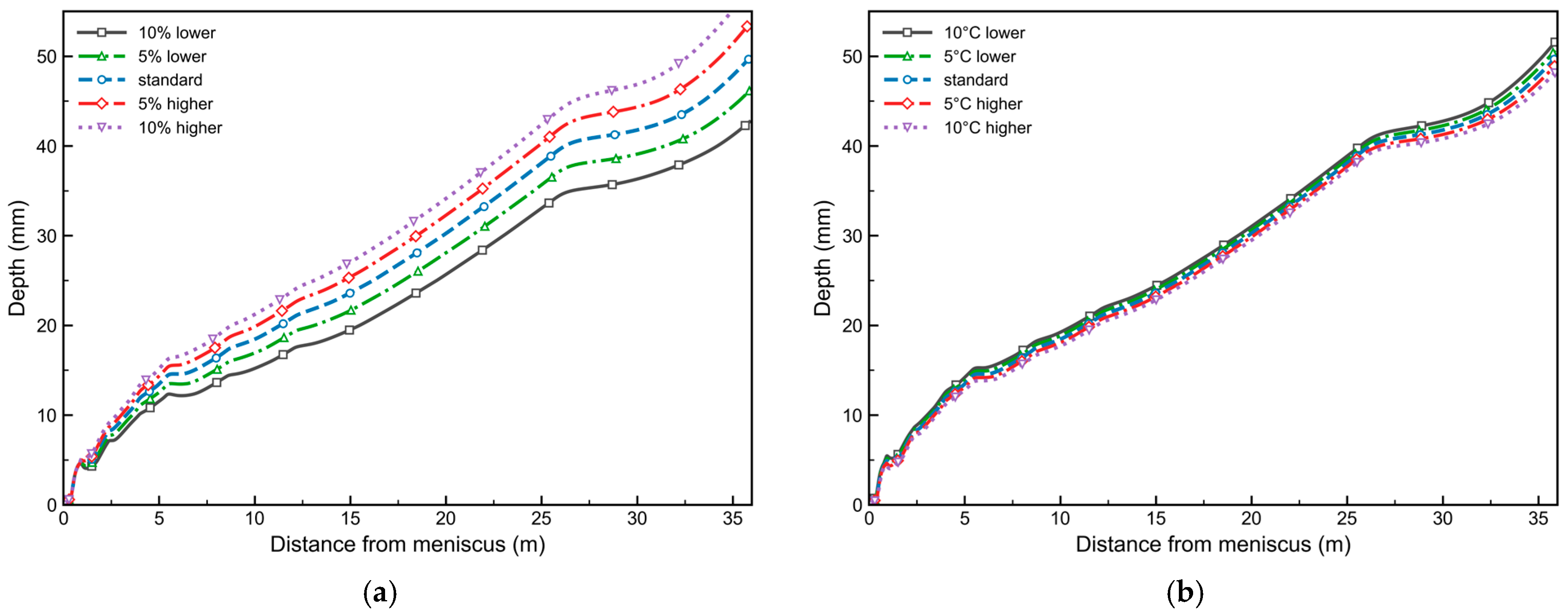
To evaluate the robustness of the optimized caster curve under possible process fluctuations, the thermal-field response was further analyzed by varying the secondary-cooling intensity and casting temperature. The equivalent heat-transfer coefficient in the secondary-cooling zone was changed by −10%, −5%, +5%, and +10% relative to the standard condition. In addition, the casting temperature was varied by ±5 °C and ±10 °C. For each case, the transient temperature field was recalculated, and the depth evolution of the internal 1200 °C isotherm was extracted.
Figure 12a shows the influence of secondary-cooling intensity on the 1200 °C isotherm depth. A stronger cooling intensity moves the 1200 °C isotherm deeper into the slab, whereas a weaker cooling intensity keeps the high-temperature region closer to the slab surface. At the bending-start position of 1.2 m from the meniscus, the extracted 1200 °C isotherm depth changes from 4.06 mm to 5.22 mm as the cooling intensity increases from 10% lower to 10% higher than the standard condition. At the straightening-end position of 19.96 m, the corresponding depth changes from 25.61 mm to 34.07 mm. This indicates that the secondary-cooling intensity has a clear influence on the spatial position of the internal high-temperature region.
Figure 12.
Effect of process-parameter fluctuations on the depth of the internal 1200 °C isotherm: (a) secondary-cooling intensity; (b) casting temperature.
Figure 12b shows the influence of casting-temperature fluctuation on the 1200 °C isotherm depth. Compared with the effect of secondary-cooling intensity, the influence of casting temperature is relatively smaller. When the casting temperature decreases from 1545 °C, the 1200 °C isotherm depth increases from 4.12 mm to 5.17 mm at 1.2 m and from 29.43 mm to 30.96 mm at 19.96 m. A lower initial casting temperature promotes cooling and shifts the 1200 °C isotherm slightly inward.
The extracted isotherm depths were then substituted into the strain-rate formulation to calculate the maximum internal strain rates in the bending and straightening regions. The results are summarized in Table 8 and Table 9. Under all cooling-intensity conditions, the maximum bending strain rate varies from to , and the maximum straightening strain rate varies from to . Under all casting-temperature conditions, the maximum bending strain rate varies from to , and the maximum straightening strain rate varies from to .
Table 8.
Effect of secondary-cooling intensity on the 1200 °C isotherm depth and maximum strain rate.
Table 9.
Effect of casting temperature on the 1200 °C isotherm depth and maximum strain rate.
All the calculated maximum strain rates remain below the measured steady-state creep-rate threshold of . Therefore, within the investigated ranges of secondary-cooling intensity and casting-temperature fluctuation, the optimized caster curve enables the internal region at 1200 °C to complete the bending and straightening process through creep deformation. This result demonstrates that the proposed curve has strong adaptability to moderate variations in thermal-boundary conditions and good robustness for practical continuous-casting operations.
4.2. Comparison Between the Conventional R9300 Caster and the Optimized Cycloid Caster
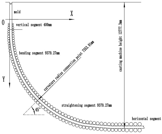
Figure 13 compares the conventional R9300 layout with the optimized cycloid caster. The optimized curve consists of a 400 mm vertical segment, a 9379 mm bending section, a 9379 mm straightening section, and a horizontal segment. It removes the basic circular arc of the original caster, while increasing the bending and straightening section lengths by 8349 mm and 7859 mm, respectively.
Figure 13.
Roll arrangement and geometry of the newly designed cycloid caster.
These extensions significantly prolonged the duration of bending and straightening deformation, allowing the slab to deform gradually throughout the entire process. This not only lowers the strain rate, but also extends the time available for creep deformation. The longer duration allows the creep effect to be fully utilized, enabling the bending and straightening to be achieved primarily through creep.
The total caster height increases by only about 0.47 m. Therefore, with the original casting speed, secondary-cooling scheme, and metallurgical length retained, the curve can be implemented mainly by rearranging the roll positions.
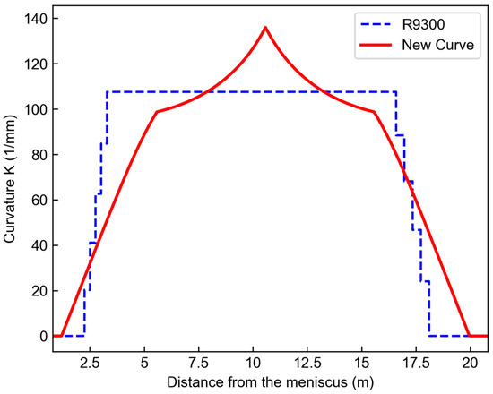
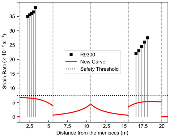
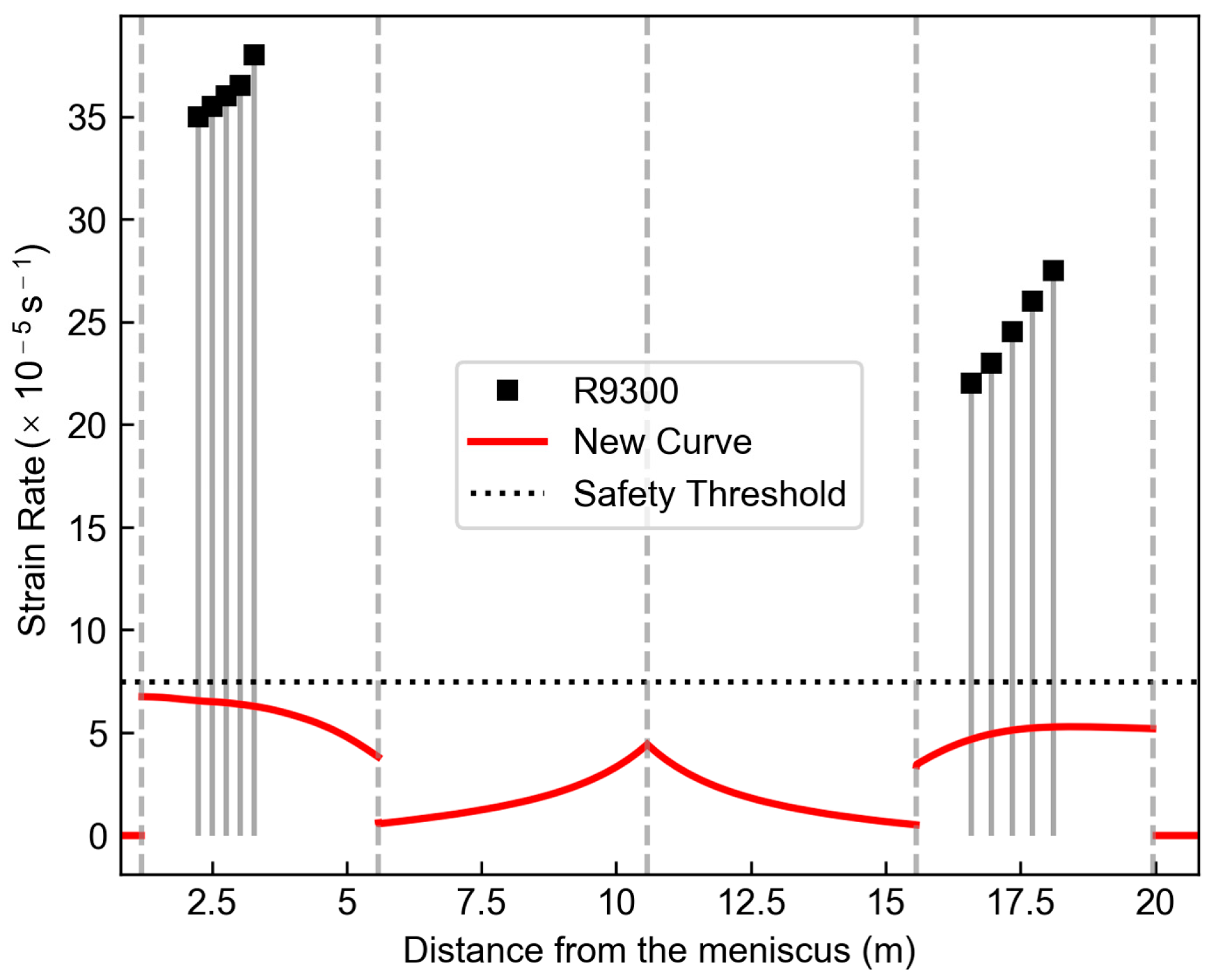
Figure 14 compares the curvature distributions. The conventional R9300 caster shows stepwise curvature changes at segment junctions, whereas the optimized curve varies continuously through the cubic transition and cycloid segments. Its minimum curvature radius is 7353.91 mm, and the smoother curvature distribution reduces abrupt local curvature changes. Figure 15 compares the 1200 °C internal strain rates. The optimized maximum strain rates are in bending and in straightening; both are lower than the measured steady-state creep-rate threshold at 1200 °C. The corresponding safety margins are approximately 9.4% and 30.3%, indicating that the 1200 °C internal region satisfies the creep bending and straightening criterion.
Figure 14.
Curvature along the optimized cycloid caster curve.
Figure 15.
Comparison of 1200 °C internal strain rates between the two caster curves.
5. Conclusions
Based on the high-temperature creep behavior of Q345C steel, a continuous bending and straightening curve was developed for an industrial R9300 slab continuous caster. The main conclusions are as follows:
- (1)
- A creep-rate-constrained caster-curve design method was established by using the experimentally measured steady-state creep rate as the design threshold. The proposed curve eliminates the conventional basic circular-arc section, maintains continuity of position, tangent, and curvature, and extends the bending and straightening sections by 8349 mm and 7859 mm, respectively. Thus, the required curvature change is distributed over a longer caster path.
- (2)
- Under the combined constraints of caster height, minimum curvature radius, and steady-state creep rate, the optimized parameters were determined as a = 2600 mm and t = 3.6 rad. The minimum curvature radius is 7353.91 mm, and the caster height increases by only approximately 0.47 m. Since the original casting speed, secondary-cooling scheme, and metallurgical length are maintained, the optimized curve can be implemented mainly by rearranging the roll positions.
- (3)
- At the internal 1200 °C isotherm, the maximum strain rates in the bending and straightening sections are and , respectively, which are 82.2% and 81.1% lower than those of the conventional caster. Both values are below the measured steady-state creep rate of Q345C steel at 1200 °C, with safety margins of 9.4% and 30.3%. Therefore, the strand region at 1200 °C and above satisfies the creep bending and straightening criterion, indicating that bending and straightening can be achieved mainly through high-temperature creep rather than concentrated plastic deformation.
- (4)
- Under ±10% secondary-cooling-intensity and ±10 °C casting-temperature fluctuations, all calculated maximum strain rates remain below the measured steady-state creep rate at 1200 °C. This indicates that the optimized curve retains robustness under the investigated thermal-boundary fluctuations.
Author Contributions
Conceptualization, X.B. and X.Z.; methodology, X.B. and X.Z.; software, Z.Z.; validation, X.B. and Z.Z.; formal analysis, X.B.; investigation, X.B.; resources, Z.Z.; data curation, X.B.; writing—original draft preparation, X.B.; writing—review and editing, X.B. and Z.Z.; visualization, Z.Z.; supervision, X.Z.; project administration, X.Z.; funding acquisition, X.Z. All authors have read and agreed to the published version of the manuscript.
Funding
This research was financially supported by the National Science Foundation of China under the Grant No. 51275446, and the Hebei Provincial Natural Science Foundation of China under the Project No. E2016203492.
Data Availability Statement
The original contributions presented in this study are included in the article. Further inquiries can be directed to the corresponding author.
Conflicts of Interest
The authors declare that they have no known competing financial interests or personal relationships that could have appeared to influence the work reported in this paper. The authors declare no conflicts of interest.
References
- Tomono, H. Development of steel continuous casting in Japan: Has Bessemer’s dream come true? Ironmak. Steelmak. 2015, 42, 242–251. [Google Scholar] [CrossRef] [Scilit]
- Luo, X.; Xie, Q.; Wang, Y.; Yang, C. Estimation of heat transfer coefficients in continuous casting under large disturbance. Int. J. Heat Mass Transf. 2017, 111, 1087–1097. [Google Scholar] [CrossRef] [Scilit]
- Pascon, F.; Habraken, A.M. Finite element study of the effect of some local defects on the risk of transverse cracking in continuous casting of steel slabs. Comput. Methods Appl. Mech. Eng. 2007, 196, 2285–2299. [Google Scholar] [CrossRef] [Scilit]
- Li, X.B.; Ding, H.; Tang, Z.Y.; He, J.C. Formation of internal cracks during soft reduction in rectangular bloom continuous casting. Int. J. Miner. Metall. Mater. 2012, 19, 21–29. [Google Scholar] [CrossRef] [Scilit]
- Han, Z.; Cai, K.; Liu, B. Prediction and Analysis on Formation of Internal Cracks in Continuously Cast Slabs by Mathematical Models. ISIJ Int. 2001, 41, 1473–1480. [Google Scholar] [CrossRef] [Scilit]
- Ai, S.; Long, M.; Yang, X.; Chen, D.; Xu, P.; Duan, H. Prediction model for crack sensitive temperature region and phase fractions of slab under continuous casting cooling rates based on finite element number of experiments. J. Mater. Res. Technol. 2023, 22, 1103–1117. [Google Scholar] [CrossRef] [Scilit]
- Yang, J.; Zhang, F.; Li, J.; Liu, W.; Wang, T.; Yuan, H.; Cang, D. Bending and straightening of a medium carbon steel continuous casting slab with low temperature end plastic groove. Materials 2022, 15, 2609. [Google Scholar] [CrossRef] [Scilit] [PubMed]
- Zhang, Z.; Ju, J.; Ji, C.; Chang, H.; Zhu, M. Corner cracking criterion in slab continuous casting: A cross-scale framework from laboratory calibration to industrial prediction. J. Manuf. Processes 2026, 171, 63–81. [Google Scholar] [CrossRef] [Scilit]
- Zhang, Z.; Ji, C.; Ju, J.; Li, K.; Zhu, M. Micromechanical behavior and microcrack evolution in continuous casting slab: Experimental characterization, multiscale simulation and industrial validation. J. Mater. Process. Technol. 2025, 340, 118866. [Google Scholar] [CrossRef] [Scilit]
- Fix, C.; Borrmann, L.; Elixmann, S.-M.; Grahe, C.; Kurenbach, S.; Senk, D. Investigations on Decreased High Temperature Ductility of Different Continuously Cast Steel Grades. Steel Res. Int. 2021, 92, 2100323. [Google Scholar] [CrossRef] [Scilit]
- Huitron, P.; Lopez, P.E.R.; Vuorinen, E.; Jalali, P.N.; Kärkkäinen, M. Identification of Cracking Issues and Process Improvements through Plant Monitoring and Numerical Modelling of Secondary Cooling during Continuous Casting of HSLA Steels. ISIJ Int. 2021, 61, 834–843. [Google Scholar] [CrossRef] [Scilit]
- Comineli, O.; Qaban, A.; Mintz, B. Influence of Cu and Ni on the Hot Ductility of Low C Steels with Respect to the Straightening Operation When Continuous Casting. Metals 2022, 12, 1671. [Google Scholar] [CrossRef] [Scilit]
- Wang, H.; Zhang, J.; Wang, C.; Yang, Z.; Wu, J.; Guan, M.; Liu, Q. Analysis and Control of the Slab Hot Ductility Behaviors Based on Nozzle Arrangement during Continuous Casting. Steel Res. Int. 2024, 95, 2300296. [Google Scholar] [CrossRef] [Scilit]
- Luo, Z. Steelmaking Machinery, 2nd ed.; Metallurgical Industry Press: Beijing, China, 1989; p. 220. [Google Scholar]
- Cheng, N.; Wang, H. Investigation and practice on single-point straightening caster with liquid core straightening. Contin. Cast. 2005, 2, 29–31. [Google Scholar]
- Zhou, L. Design & calculation of multipoint straightening. CFHI Technol. 2009, 6, 10–12. [Google Scholar]
- Deisinger, M.; Tacke, K.H. Unbending of continuously cast slabs with liquid core. Ironmak. Steelmak. 1997, 24, 321–328. [Google Scholar]
- Wu, J.; Du, S. Application of VAI high-efficiency billet caster technology in Maanshan steel. Contin. Cast. 2004, 6, 23–24. [Google Scholar]
- Wang, M.; Hu, L.; Yan, Z.; Tian, X.; Su, Q. Production practice of steel continuous casting machine introduced by VAI. Iron Steel 2004, 39, 173–175. [Google Scholar]
- Li, X. Low-head continuous casting machine with two smooth continuous straightening areas. Iron Steel 1996, 31, 31–35. [Google Scholar]
- Jing, F.; Li, X.; Yang, L.; Sun, H.; Wang, T.; Chen, Z. Optimization of continuous bending and straightening curve of vertical-arc slab caster. Iron Steel 2009, 44, 23–27. [Google Scholar]
- Jing, F.; Li, X.; Wang, T.; Chen, Z.; Sun, H. Research and application of strand’s new-ideal continuous straightening curve. China Mech. Eng. 2009, 20, 1240–1244. [Google Scholar]
- Jing, F.; Zhang, X.; Meng, J.; Guo, W. Analysis of the numerical solution to the ideal straightening curve equation of continuous casting slab. Heavy Mach. 2004, 3, 49–52. [Google Scholar]
- Wang, T.; Chen, Z.; Li, X.; Man, Y. Application of continuous straightening on slab casting. Contin. Cast. 2007, 5, 9–11. [Google Scholar]
- Ashby, M.F.; Jones, D.R.H. Engineering Materials 1; Elsevier Science: New York, NY, USA, 2011. [Google Scholar]
- Liu, C.; Gadelmeier, C.; Lu, S.; Yeh, J.; Yen, H.; Gorsse, S.; Glatzel, U.; Yeh, A. Tensile creep behavior of HfNbTaTiZr refractory high entropy alloy at elevated temperatures. Acta Mater. 2022, 237, 118188. [Google Scholar] [CrossRef] [Scilit]
- Dong, S.; Gong, Z.; Chen, Z.; Qu, Y.; Chen, R.; Liu, S.; Li, G. High temperature tensile creep behavior and microstructure evolution of Ti60 alloy rolled sheet. Mater. Today Commun. 2024, 41, 110805. [Google Scholar] [CrossRef] [Scilit]
- Wang, T.; Kai, X.; Huang, L.; Peng, Q.; Sun, K.; Zhao, Y. High temperature creep behavior and creep mechanism of in situ (ZrB2+Al2O3)np/7055 Al nanocomposites. J. Alloys Compd. 2024, 981, 173662. [Google Scholar] [CrossRef] [Scilit]
- Pan, X.; Jia, C.; Qiu, C. On the high-temperature creep and fatigue behaviours of an advanced hot-extruded nickel-based alloy. Mater. Des. 2025, 257, 114514. [Google Scholar] [CrossRef] [Scilit]
- Gai, Y.; Zhang, R.; Cui, C.; Zhou, Z.; Tao, X.; Tan, Y.; Zhou, Y. Creep behavior and microstructure evolution of a novel Ni-Co-based superalloy with long-life designed for high temperature application. Mater. Sci. Eng. A 2025, 935, 148396. [Google Scholar] [CrossRef] [Scilit]
- Zhang, X.; Guo, L. Creep straightening technology of continuous casting slab based on high-temperature creep property. ISIJ Int. 2017, 57, 76–83. [Google Scholar] [CrossRef] [Scilit]
- Sui, Y.; Zhang, H.; Zhang, X. Study on the creep behavior and microstructure evolution of a low alloy steel in continuous casting processing. Mater. Sci. Eng. A 2022, 838, 142828. [Google Scholar] [CrossRef] [Scilit]
- Sui, Y.; Lu, H.; Zhang, X. A new continuous bending and straightening curve based on the high-temperature creep property of a low-alloy steel continuous casting slab. Metals 2025, 15, 1059. [Google Scholar] [CrossRef] [Scilit]
- Han, Z.; Feng, K.; Qu, T.; Cao, J.; Ren, B.; Mao, J. The discussion about the determination of basic radius for extra-thick slab caster. Ind. Heat. 2013, 42, 19–21. [Google Scholar]

Disclaimer/Publisher’s Note: The statements, opinions and data contained in all publications are solely those of the individual author(s) and contributor(s) and not of MDPI and/or the editor(s). MDPI and/or the editor(s) disclaim responsibility for any injury to people or property resulting from any ideas, methods, instructions or products referred to in the content. |
© 2026 by the authors. Licensee MDPI, Basel, Switzerland. This article is an open access article distributed under the terms and conditions of the Creative Commons Attribution (CC BY) license.