


Abstract
To improve temperature uniformity and reduce thermal stress-induced cracking during laser directed energy deposition (laser DED) repair of TiAl blades, this study proposes a refined induction heating coil design based on coupled electromagnetic-thermal finite element simulation. A temperature-dependent model of the induction heating process for a cast 45XD TiAl blade was established and used to compare circular and elliptical coil cross-sectional shapes. The elliptical coil reduced the magnetic field concentration at the leading and trailing edges and decreased the maximum temperature difference across the blade cross-section to below 100 K, thereby improving transverse temperature uniformity. To further improve the temperature distribution along the blade length, a variable-pitch solenoid coil with sparse turns in the middle and dense turns near both ends was designed. This arrangement improved the balance between local heat generation and heat dissipation and reduced the temperature variation within the central 10 cm region of the blade to about 10 K. Experimental validation showed engineering-level agreement with the simulation results, and the blade body was stably maintained at 1020–1030 K, satisfying the preheating requirement for laser DED repair of TiAl blades within the tested design set.
1. Introduction
Titanium-aluminum alloy (TiAl) demonstrates exceptional high-temperature properties, low density and excellent oxidation resistance. This is attributed to the high-temperature strength and creep resistance of its γ-TiAl phase, making it an ideal material for lightweight high-temperature components [1,2,3]. The industry has successfully employed centrifugal precision casting techniques to fabricate TiAl low-pressure turbine blades, which have subsequently undergone and passed strict engine tests, signifying a notable advancement in the engineering utilization of this material [4,5].
Under the harsh operating conditions of aero-engines, turbine blades are susceptible to surface damage. The high manufacturing costs of TiAl blades make the direct replacement economically inefficient. Consequently, the development of efficient repair technologies is of significant value for extending the service life of blades and reducing lifecycle cost [6]. With the advancement of additive manufacturing technology, processes like laser directed energy deposition (DED) have been increasingly employed in the repair of nickel-based alloy turbine blades [7,8]. In recent years, research on additive manufacturing for TiAl alloys and TiAl blades based on laser DED technology has also been emerging [9,10].
However, TiAl alloys exhibit poor ductility at room temperature and are prone to cracking due to thermal stress during the laser repair process. Studies indicate that their brittle-ductile transition temperature ranges from approximately 620–800 °C [11]. Preheating the TiAl alloys to the temperature above this temperature range can mitigate the tendency for cracking and significantly enhance the laser DED quality [12]. As a non-contact, efficient, controllable and clean heating process, induction heating is suitable for blade components with complex shapes and high cleanliness requirements [13,14], making it the preferred solution for the preheating process in TiAl blade repairs. However, TiAl is a non-magnetic material, which makes the induction heating of TiAl blade rely on high-frequency eddy currents. Additionally, its low thermal conductivity can lead to uneven temperature distribution due to skin effects and sharp corner effects, bringing significant challenges to the uniform preheating of blade components [15].
Regarding the uniformity issue of induction heating distribution, finite element (FE) simulation has become an important tool for coil design and optimization. Huo et al. analyzed the impact of a single-turn conformal coil on the temperature distribution of a blade through simulation [16]. Choubey et al. optimized the design of a solenoid with gradually changing diameter through simulation, achieving uniform heating of cylindrical metal workpieces [17]. Jiang et al. conducted simulation and experimental verification on solenoid induction heating for irregularly shaped steel bar parts [18]. Recent studies also show that substrate preheating can suppress cracking in TiAl alloy processed by laser DED [19], that induction heating is widely used because of its rapid, clean and accurately controllable thermal response [20], and that coil layer arrangement, pitch, heating distance and coil position strongly affect heating rate and temperature uniformity [21,22]. A recent experimentally validated COMSOL study further demonstrated that innovative coil architecture can markedly improve temperature uniformity in fast sheet-metal induction heating [23]. However, existing research mostly focuses on regular shapes or magnetic materials. For TiAl blades with 3D aerodynamic curved surface, there is still a lack of detailed research on how to achieve overall uniform preheating through coil structure design refinement.
Therefore, this study constructs an electromagnetic-thermal multi-field coupling model for TiAl blade induction heating and conducts FE simulation analysis on temperature uniformity under different coil structure configurations, with the coil cross-sectional shape and pitch distribution as the key design variables. The reliability of the simulation results is verified through experiments, aiming to provide technical value for the uniform preheating of complex-shaped TiAl components.
2. Materials and Methods
2.1. Induction Heating Theory
Induction heating technology can achieve rapid heating of metallic materials and the fast increase in material temperature based on the principle of electromagnetic induction [24]. By applying the alternating current flowing through the copper coil, an alternating magnetic field in the heating coil generates. When the magnetic field passes through the metal workpiece, it induces eddy currents inside the workpiece. As the eddy currents flow through the workpiece, it is converted into Joule heat due to resistance, realizing the conversion of electrical energy into thermal energy [25]. According to Faraday’s law of electromagnetic induction, when an alternating magnetic field passes through a conductor, induced electromotive force (EMF) ε will be generated in the conductor.
In Equation (1), Φ represents magnetic flux (unit is Wb) and t represents time (unit is second). The induced EMF further drives the formation of eddy currents within the conductor. As the eddy currents flow through the conductor, they generate Joule heat due to the resistance of the conductor. The local volumetric Joule heating can be written as P = σ|E|2. For an order-of-magnitude estimate, the induced electric field around a representative eddy current loop with characteristic dimension d can be scaled as E ~ ωBd [26]. Thus, the heating-power-density trend used for physical interpretation in this study can be written as Equation (2):
where P is the thermal power density per unit volume (W/m3), σ is the conductivity of the workpiece material (S/m), E is the induced electric field (V/m), ω is the angular frequency of the alternating current (rad/s), B is the magnetic flux density (T) and d is the characteristic size of the eddy current loop (m). Equation (2) is used only as a scaling relation; the numerical results were obtained by directly solving the coupled electromagnetic and thermal fields in the FE model.
The temperature variation inside the workpiece follows the unsteady heat conduction equation, which can be expressed as Equation (3) when considering the eddy current heat source involved:
where ρ represents the material density (kg/m3), cp is the heat capacity at constant pressure (J/(kg·K)), T stands for temperature (K), t represents time (s), k is the thermal conductivity (W/(m·K)) and Q is the eddy current heat source (W/m3).
In the process of high-frequency induction heating, the significant skin effect makes the electric current concentrate and flow in a thin layer on the surface of the workpiece. The skin depth δ can be calculated using Equation (4):
where ρ represents the resistivity of the material (Ω·m), μ is the magnetic permeability (H/m), ω = 2πf is the angular frequency of the current (rad/s) and f stands for the frequency of the alternating current (Hz).
The induction heating is a typical electromagnetic-thermal multiphysics coupling process. The alternating magnetic field generates eddy currents within the blade and converts them into Joule heat, leading to an increase in blade temperature. Temperature changes alter the physical properties of the alloy, such as electrical conductivity and thermal conductivity, which in turn affect the magnetic field distribution and the efficiency of eddy current generation. Based on multiphysics coupling, this study integrates the aforementioned electromagnetic induction and heat conduction equations, combined with temperature-dependent material parameters, to build a coupled electromagnetic-thermal simulation model.
2.2. Geometric Modeling and Material Properties
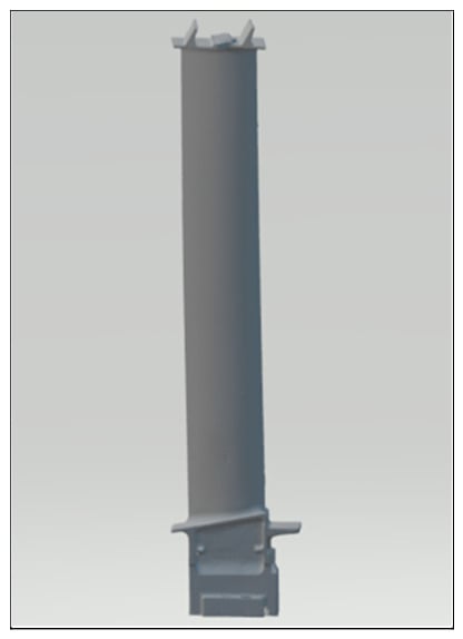
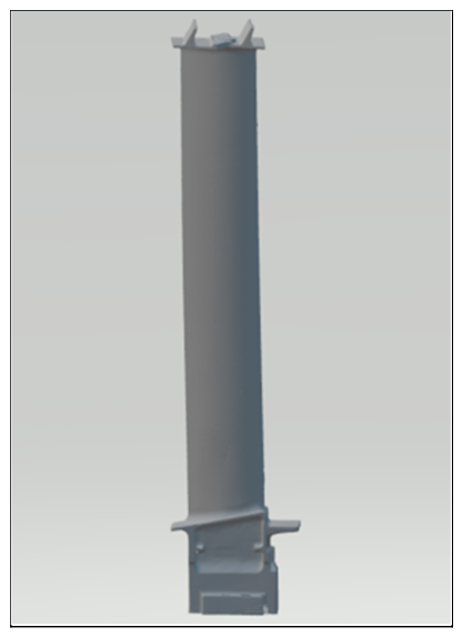
This study takes typical TiAl blades as a research example. The blade material is cast 45XD TiAl alloy with a nominal composition of Ti-45Al-2Nb-2Mn-1B (at.%). The length of the whole blade from the dovetail to the tip shroud is 323 mm. The length of airfoil is 273 mm and the chord width is about 40 mm for the TiAl blade. The maximum airfoil thickness is about 3.8 mm and it locates at approximately one-third of the chord length from the leading edge. The total surface area of the pressure and suction sides of the airfoil is 11,305.32 mm2. To balance model accuracy and computational efficiency, a simplified modeling process was performed based on the raw point cloud data from three-dimensional laser scanning of the surface of casting blade. Figure 1 shows the 3D model of the TiAl blade finally built from the treatment of the scanning raw point cloud data.
Figure 1.
The simplified 3D model of the TiAl blade.
Considering the factors such as heating efficiency, coil manufacturing difficulty and compatibility with the laser DED process, this study has decided to use a solenoid coil as the basic coil structure that was wrapped around the exterior of the blade during heating. In practical applications, induction heating coils are generally made of a hollow copper tube with cooling water flowing inside. However, due to the significant skin effect under the high-frequency electrical current, the current is almost exclusively distributed on the outer surface layer of the copper tube, which means that the simulation result of the hollow tube coil would be very similar to that of a solid copper wire coil. At 100 kHz, the skin depth of copper is approximately 206 μm. Therefore, the high-frequency current remains concentrated near the outer surface in both the hollow tube and solid wire. Therefore, to enhance the computational speed in the simulation calculation, the copper tube coil structure was simplified to the copper wire coil in the simulation model. A solid copper wire with a diameter of 1 cm was used to construct the desired coil shape.
In the physical experimental system for validation, the induction power supply was coupled with a recirculating water chiller (rated cooling capacity 15 kW), a pressure pump (20 m head) and a 70 L water tank. When the blade was heated to the target temperature in a practical operation, the surface temperature of water-cooling coil Tcoil was measured and it was around 323 K, i.e., 23 K larger than Ambient temperature (T0 = 300 K), which means the temperature rise in coil (ΔTcoil = Tcoil − T0) was very limited. Thereafter, the blade temperature was maintained at the target temperature for 2 min with the closed-loop control power system. The power supply was controlled to be ON and OFF at a Hz-level frequency to ensure that the fluctuation of the blade temperature was very small. During the 2 minute period, the water chiller system was continuously working and the surface temperature of the water-cooling coil kept around 323 ± 5 K stably. So it is reasonable to infer that the coil was at an approximately constant temperature component under the practical condition. Also, the very limited ΔTcoil means an ignorable influence on blade radiative heat transfer in the heating simulation. So the coil surface was not included as a radiating surface in the simulation.
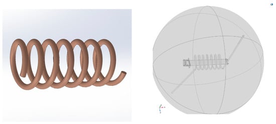
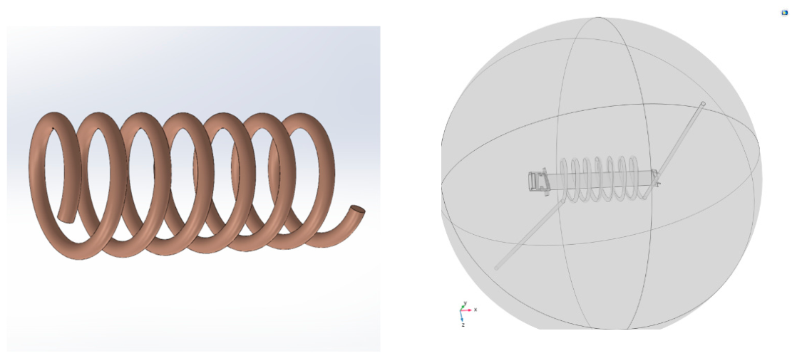
To simulate the radiative heat dissipation of the high-temperature blades, an atmosphere sphere was setup outside the blade and coil as the calculation area. Figure 2 shows the modeling of the solenoid coil and the combined model of the coil-blade-atmosphere sphere.
Figure 2.
Induction heating simulation model of the TiAl blade (Left: solenoid coil made of solid copper wire; Right: coil-blade-atmosphere sphere model).
The following information about the material properties of each component in the FE simulation model was inputted before the computation.
- The coil material is copper (using physical properties data in the built-in material library of the FEA software);
- The gas inside the atmosphere ball is argon (the blade was surrounded by argon to prevent oxidation of the blade under high temperature);
- The heat capacity at constant pressure and thermal conductivity of TiAl alloy are temperature-dependent parameters whose continuous functions were obtained through specific curve fitting with the measured discrete data within the range of 100–800 °C. The original discrete thermophysical data were provided by the blade manufacturer at 100 °C intervals, and the fitted relations were slightly extrapolated above 800 °C (1073 K) to the simulated target region near 1100 K. Because no phase transformation is expected in 45XD TiAl near this interval, the extrapolation was used for the present engineering comparison [27];
- The resistivity of TiAl is determined using a temperature-based linear correlation model, combined with empirical measurements and software simulation results;
Table 1 presents the critical physical properties data of the 45XD TiAl alloy used in the FE simulation.
Table 1.
The critical physical properties data of the TiAl alloy used in the FE simulation.
2.3. Simulation Configuration and Mesh Generation
In the physical field simulation of induction heating, a multiphysics field coupling of electromagnetic field and solid heat transfer is adopted to perform analysis and calculation of coil geometry, frequency domain and transient state analysis. The model was built in COMSOL Multiphysics (version 6.2). The study sequence included three steps: coil geometry analysis, frequency-domain electromagnetic solution, and transient thermal analysis. The electromagnetic solution calculated the magnetic field and eddy current heat source, which was then coupled into the transient heat-transfer calculation with temperature-dependent material properties. Default solver settings were used for each step. The outer boundary of the atmosphere sphere was assigned as magnetic insulation and thermal insulation. The blade surface exchanged heat with the ambient environment through surface-to-ambient radiation with an emissivity of 0.9, while convective heat transfer was neglected. The emissivity value was calibrated in preliminary tests by embedding a thermocouple near the surface of a heated 45XD TiAl sample and adjusting the emissivity setting of the infrared pyrometer until the pyrometer reading matched the thermocouple temperature. The copper coil surface was excluded from the radiation setting because the physical coil is actively water-cooled and its temperature rise is small compared with that of the blade. The key parameters setting for the simulated physical field was listed in Table 2.
Table 2.
The key parameters setting for the simulated physical field.
Since TiAl alloy is a non-ferromagnetic material whose relative permeability is about 1, a higher frequency magnetic field is needed for achieving effective induction heating. Based on engineering experience and the parameters of the mainstream power supply commercially available, the coil current frequency is set to 100 kHz. Under this frequency, the skin depth of TiAl alloy is approximately 1.3 mm. Because the blade body thickness is only 2–4 mm, even though most of the induced current is concentrated in the surface layer, the temperature difference between the surface layer and the interior can be rapidly reduced through short-distance heat conduction. Therefore, the radial temperature gradient was not treated as a separate design objective.
The simulation adopts an adaptive mesh generation strategy. Two boundary layers of 1.3 mm thickness were added in the blade region to accurately capture the impact of the skin effect. To balance computational accuracy and efficiency, the coil structure was meshed with fine free tetrahedral grid, while the coarse free tetrahedral grid was used to generate mesh in the large atmosphere sphere region.
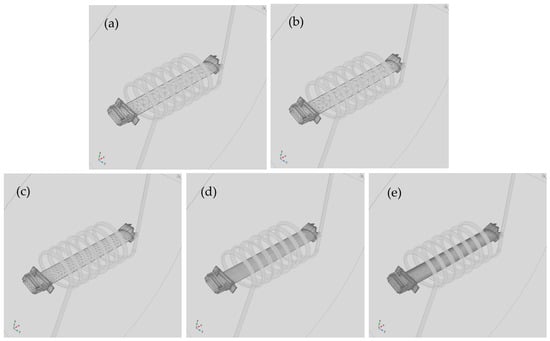
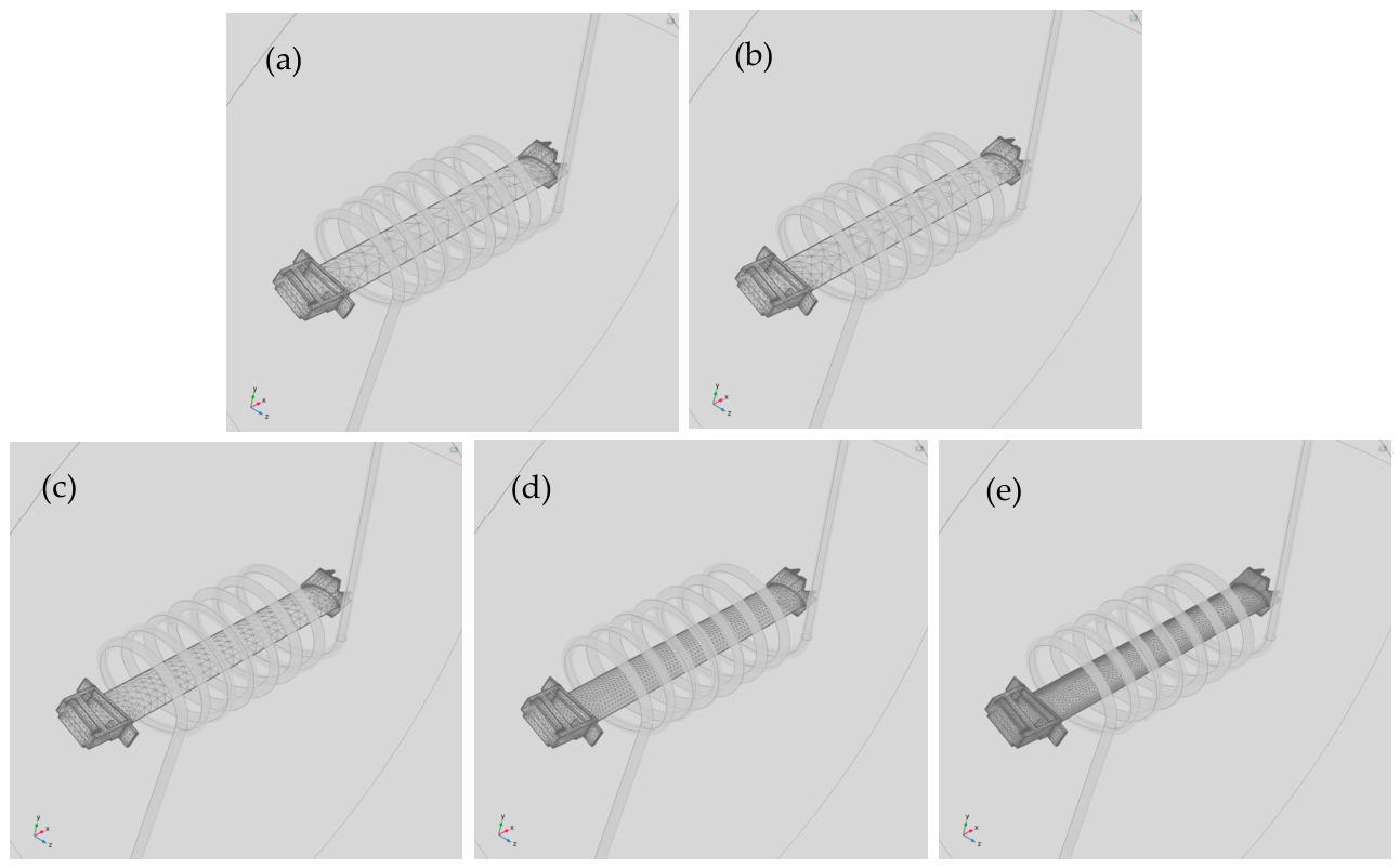
A mesh-convergence analysis was conducted to evaluate the influence of blade-domain mesh density on the simulated thermal response. COMSOL provides several preset mesh densities. An overly coarse mesh may reduce the accuracy of the electromagnetic-thermal solution, whereas an excessively fine mesh can greatly increase the computational cost. Therefore, there are five kinds of preset blade mesh density—namely coarse, normal, fine, finer and extra fine—as shown in Table 3 and Figure 3, were compared under the same representative heating condition. The coil geometry, current amplitude, excitation frequency, and heating time were kept unchanged at 800 A, 100 kHz, and 60 s, respectively. Only the blade mesh density was varied. The coil mesh was kept refined and the atmosphere–sphere mesh was kept coarsened in all cases. The maximum blade temperature after heating was selected as the convergence indicator because it is sensitive to localized heating near the blade edges.
Table 3.
Mesh-convergence results for different blade mesh densities.
Figure 3.
Mesh results under different blade mesh densities: (a) coarse, (b) normal, (c) fine, (d) finer, and (e) extra fine.
The results in Table 3 showed that the predicted maximum temperature changes from 1078 K for the coarse mesh to 1066 K for the extra fine mesh. When the mesh is refined from fine to finer, the maximum temperature changes by only 2 K, while the computation time increases from 363 s to 920 s. Compared with the extra fine mesh, the fine mesh gives a maximum temperature difference of 3 K, corresponding to a relative difference of 0.28%, but requires only about 26% of the computation time of the extra fine mesh. Further refinement therefore provides only a marginal change in the predicted peak temperature while substantially increasing the computational cost. Considering the balance between accuracy and efficiency, the fine blade mesh was selected for the subsequent simulations.
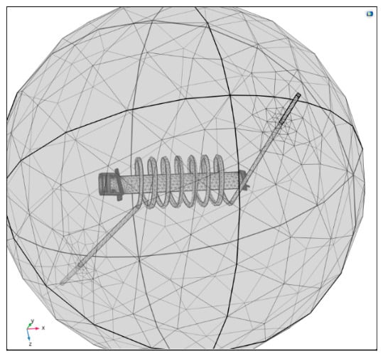
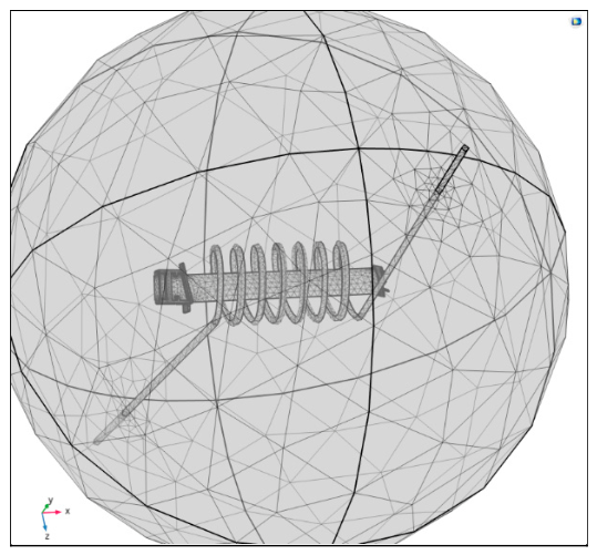
After mesh generation, the blade region contains a total of 21,192 elements, with a minimum element quality of 0.008118 and an average quality of 0.5746, meeting the computation requirements on the simulation accuracy. Figure 4 shows the overall coil-blade-atmosphere sphere model after mesh generation.
Figure 4.
The meshing of coil-blade-atmosphere sphere model.
3. Heating Coil Design and Simulation Result
3.1. Requirement Analysis and Design Objectives
After a period of service, the airfoil area of the after-service blade (excluding protruding areas such as the shroud, platform and dovetail) often experiences little damage and few defects, requiring the repair treatments such as laser DED process to enable the blade to continue serving. Therefore, the blade airfoil is the area of focus in this study.
To improve the versatility of the heating device, simplify the heating operation process and reduce thermal stress, it is necessary to uniformly heat the majority of blade airfoil area and minimize the temperature difference at various locations within the whole repair area. Preliminary research has shown that the substrate temperature window for achieving satisfactory laser DED cladding results in this TiAl alloy is approximately 1000–1100 K. Excessively higher or lower temperatures may lead to the worse laser DED cladding quality and even cause significant phase transformations of the TiAl alloy, thereby compromising its properties and performance. After the heating is completed, the coil wrapped around the blade needs to be removed from the airfoil area so that the laser DED cladding nozzle could move directly above the defect location. During the time period of this movement (about several seconds), the blade will naturally dissipate heat which results in a temperature drop of the blade airfoil. Therefore, the target heating temperature needs to be set above 1000 K to compensate for the heat dissipation loss. Experimental measurements indicate that the temperature of the blade body drops by approximately 100 K during the nozzle movement period, so the target heating temperature is set at 1100 K.
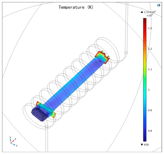
If a long solenoid coil is used to wrap and heat the entire blade, as shown in Figure 5, it can achieve approximately uniform temperature distribution in the blade airfoil area. However, sharp protruding regions such as the blade tip shroud and platform area will overheat rapidly due to the sharp corner effect and skin effect. Before the airfoil area reaches the target temperature, the temperature of these sharp regions has already exceeded the phase transition temperature of TiAl alloy, leading to the microstructure deterioration and softening deformation. Therefore, it is necessary to optimize the coil length so that the platform and blade tip are located outside the solenoid end faces because the magnetic field outside of the solenoid end faces attenuates rapidly with only a small heating effect on the sharp tip and platform region.
Figure 5.
The heating simulation of a long solenoid coil wrapped around the blade.
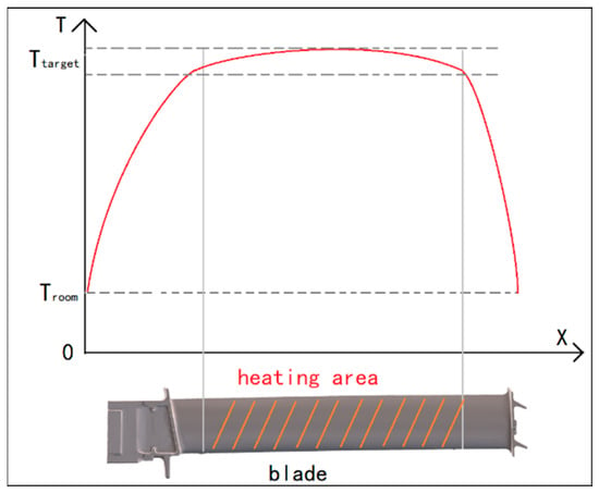
As shown in Figure 6, the temperature distribution along the direction of blade length needs to exhibit the characteristics of a steep drop at both ends and flat in the middle region which means the temperature in most of the middle area of the blade airfoil remains stable around the target temperature all the time, while the temperature in the areas near the platform and tip shroud decreases rapidly. In addition, the temperature difference within the cross-section of the blade airfoil should be small enough because the material thickness at the leading and trailing edges of the blade is significantly smaller than that in the middle area of the blade cross-section. Improper heating design may cause the temperature at the edges of the blade to be higher than that in the middle area, leading to unwanted phase transitions at the edge. Therefore, the coil design should minimize not only the temperature difference in the airfoil area along the direction of blade length, but also the temperature difference between the middle area and the edge of blade in the cross-section, so as to make the temperature distribution of the entire heating area uniform. This is also the objective of the heating coil design.
Figure 6.
The expected temperature distribution along the direction of blade length (Ttarget: target temperature; Troom: room temperature).
3.2. Heating Coil Design
Considering the manufacturing difficulty and geometry adaptability, a multiple-turn solenoid is adopted as the basic coil structure whose main parameters include the total length, cross-sectional shape and pitch distribution of the coil. The research object of this study is a TiAl blade with a fixed length of airfoil area. The cross-sectional shape of each turn of the solenoid is uniform for manufacturing ease and the diameter is slightly larger than the dimension of the protruding area of the blade tip, making it easy to insert so as to wrap the blade and remove from the blade tip end. Therefore, the study focuses on refining the two key parameters of the coil, i.e., the cross-sectional shape and pitch arrangement. In the simulation, different coil structures are designed for comparative analysis and the selected combination of the cross-sectional shape and pitch arrangement is determined after iterative parametric refinement. More intermediate designs were calculated than those shown in this paper. Table 4 reports representative designs used to explain the main trends. Because no objective function was minimized over the full design space, the selected coil is not claimed to be a mathematically global optimum.
Table 4.
Different coil designs in the FE simulation.
3.3. The Comparative Analysis of Cross-Sectional Shapes
The circular and elliptical single-turn coils (Design No.1 and No.2 in Table 4) were compared and analyzed to investigate the influence of cross-sectional shape on temperature difference at different positions of a blade cross-section. In all coil models, the axis of airfoil section is aligned with the corresponding coil center to ensure that the coil-blade clearance is roughly evenly distributed around the blade. For an airfoil cross-section with a chord width of 40 mm and a maximum thickness of 3.8 mm, using a circular single turn coil with an internal diameter of 80 mm can achieve a coil-blade clearance of about 20 mm at blade edge region and a clearance of 35~38 mm from the concave/convex to the coil. By using elliptical coils with an internal diameter along the long axis of 110 mm and an internal diameter along the short axis of 70 mm, the clearance gaps of about 35 mm at blade edge region and about 33 mm at the concave/convex region can be obtained, respectively.
Under high-frequency magnetic fields, the skin effect causes the heat generation of the blade to concentrate on the surface layer, while the interior was passively heated up through thermal conduction. Due to the small heat capacity at the thin leading and trailing edges and the large heat capacity at the thick middle area of cross-section, the edge regions are prone to overheating. By using elliptical cross-section coils, the magnetic field strength in the both edge regions can be reduced specifically, thereby improving the uniformity of the temperature distribution in the cross-section.
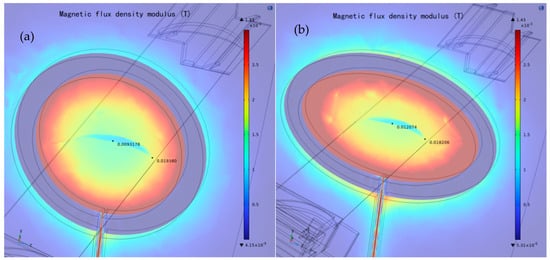
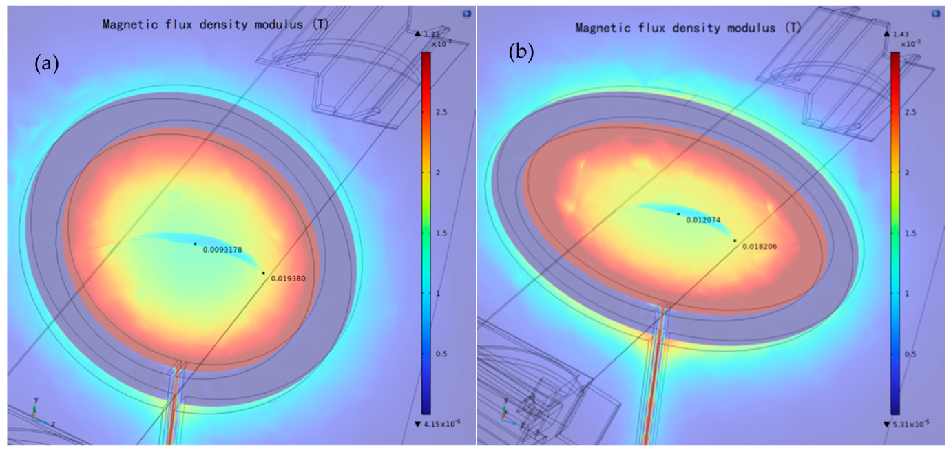
Figure 7 showed the magnetic field distribution at the blade cross-section generated by two types of single-turn coils (design No.1 and No.2 in Table 4). The excitation current was 5000 A at 100 kHz for both cases. In the distribution of the magnetic flux density generated by the circular coil, the value at the leading edge of the blade is 0.01938 T, while the value in the middle region is 0.0093 T that is approximately 48% of the value at the leading edge. For the elliptical coil design, the magnetic flux density generated at the leading edge is 0.0182 T and the density in the central region is 0.0121 T that is approximately 66% of that at the leading edge. It showed that the magnetic field distribution uniformity of elliptical coil is significantly better than that of circular coil.
Figure 7.
The magnetic field distribution at the blade cross-section generated by different coils (a): circular coil; (b): elliptical coil.
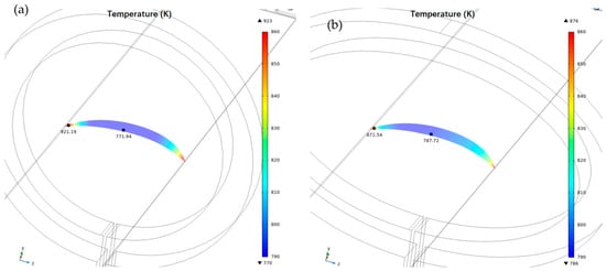
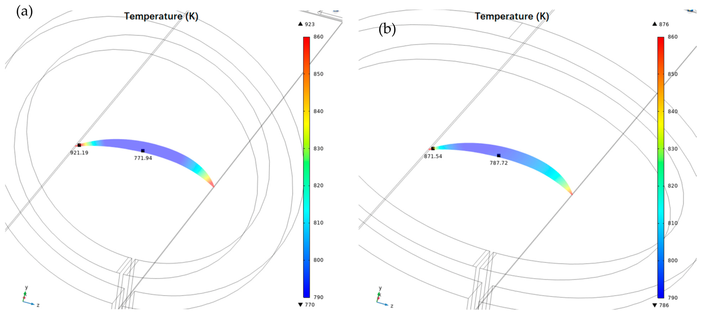
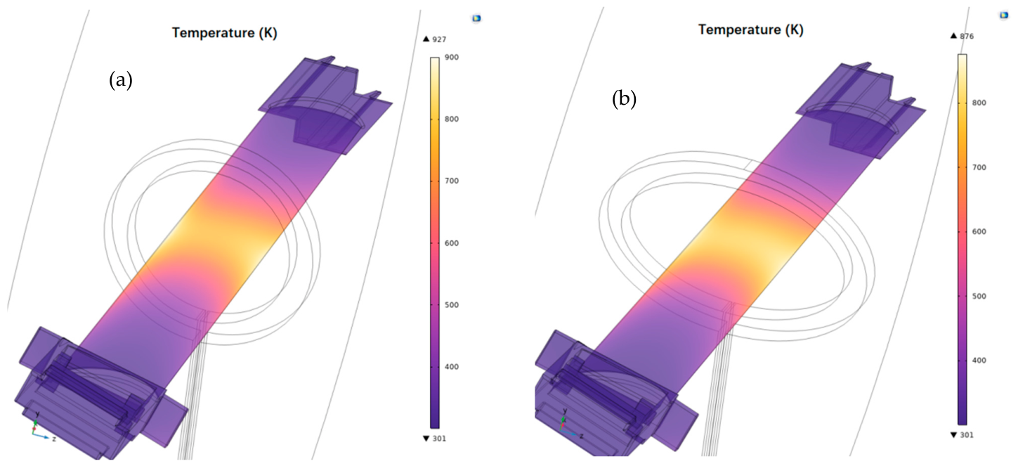
By applying the same coil current and heating for the same time, both types of coils can significantly increase the temperature of the blades. The temperature contours in Figure 8 were extracted at 1.8 min, when the average blade temperature was close to 850 K in both cases. Although the heating rates were not exactly identical, the comparison at the same time and nearly the same average temperature provides a consistent basis for evaluating cross-sectional uniformity. The maximum temperature difference in the case of circular coil is 153 K, i.e., the temperature varies from 770 K to 923 K, while the maximum temperature difference in the case of elliptical coil is only 90 K (the temperature ranges from 786 K to 876 K), which is 58.8% of that of the circular coil, effectively alleviating the overheating at the leading and trailing edges.
Figure 8.
The temperature distribution of the airfoil cross-section (a): circular coil; (b): elliptical coil.
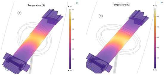
In addition, the above conclusion can be further verified through the comparison of the overall temperature distribution cloud map between the two types of single-turn coils, as shown in Figure 9. Under the same temperature scale, the overheating of the leading edge and trailing edges is prominent in the case of circular coil (left picture in Figure 9), while the temperature distribution in the cross-section in the case using elliptical coil (right picture in Figure 9) is more uniform. Under the premise that the local temperature of the blade does not exceed the safety threshold value, the elliptical coil can heat the main area of the blade airfoil to a higher temperature compared to the circular coil, which is helpful for the stability and quality of the laser DED cladding process. Therefore, the elliptical cross-section was selected for subsequent solenoid-coil designs.
Figure 9.
The overall temperature distribution cloud map of different cross-sectional single-turn coils (a): circular coil; (b): elliptical coil.
3.4. Result Analysis of Pitch Arrangement Refinement
Based on the No.3~No.5 elliptical coil design in Table 4, the influence of different pitch arrangement of coil on the temperature distribution along the length direction of the blade was explored. The current amplitude was fixed at 800 A and the frequency was fixed at 100 kHz for these multi-turn solenoid simulations.
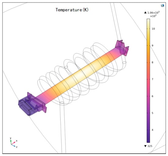
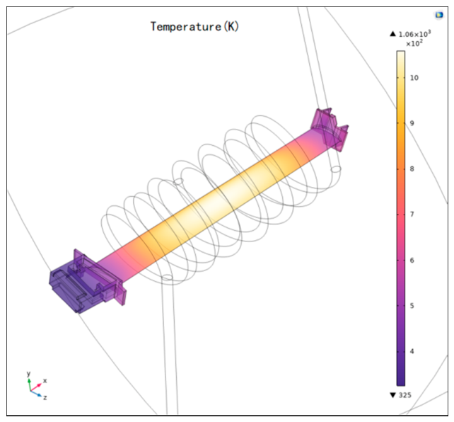
Due to the rapid attenuation of the magnetic field outside of the solenoid coil region, there is little eddy current heating in the platform and tip shroud areas at both ends of the blade. In addition, the heat capacity in these areas is large, which makes the temperature distribution of blade airfoil naturally exhibit ‘high in the middle and low at both ends’ along the direction of the blade length. Figure 10 shows the heating effect of No.3 coil design in Table 4 (uniform and identical pitches). The maximum temperature in the middle area of the blade airfoil reached 1060 K and gradually decreased from the center to both sides. The temperature difference in the whole heating region is large, which is not quite suitable for the laser DED process repair of the TiAl blade.
Figure 10.
The overall temperature distribution of 7-turn elliptical coils with uniform and identical pitches.
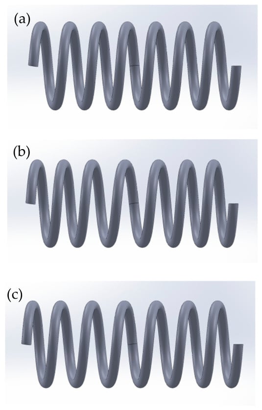
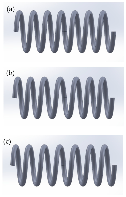
To improve the temperature uniformity along the direction of the blade length, the strategy of increasing the pitch in the hotter region and decreasing the pitch in the less hot region is adopted. The large pitch could weaken the magnetic field strength and reduce the heating rate, whereas small pitch can enhance the magnetic field strength and increase the heating rate, which realizes the regulating balance between heat generation and heat dissipation in different areas of the blade airfoil and eventually produces a more uniform temperature distribution. Both No.4 and No.5 coil designs in Table 4 adopted the variable pitch design of “sparse in the middle and dense at both ends”, as shown in Figure 11, with only the specific pitch values differing.
Figure 11.
The 7-turn elliptical solenoid coil design with different variable-pitch arrangements: (a) No.3 design: 30-30-30-30-30-30-30 mm; (b) No.4 design: 26-28-33-36-33-28-26 mm; (c) No.5 design: 27-28-32-33-33-29-28 mm.
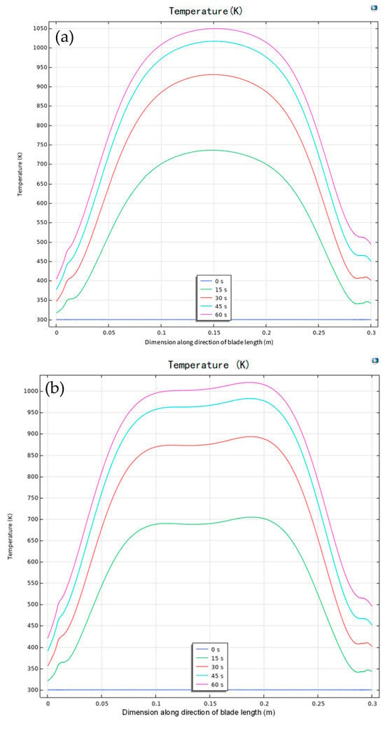
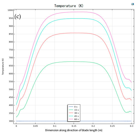
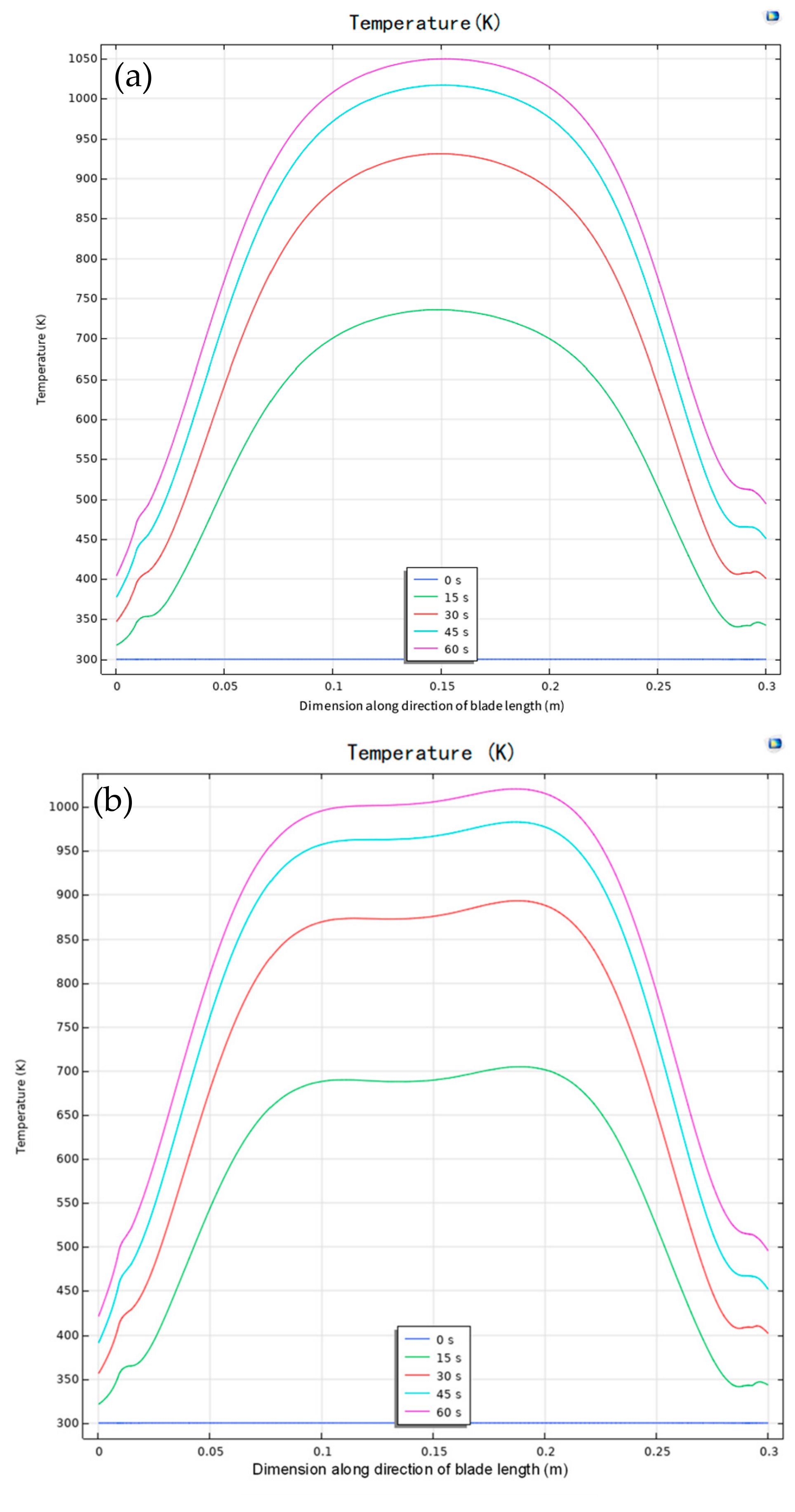
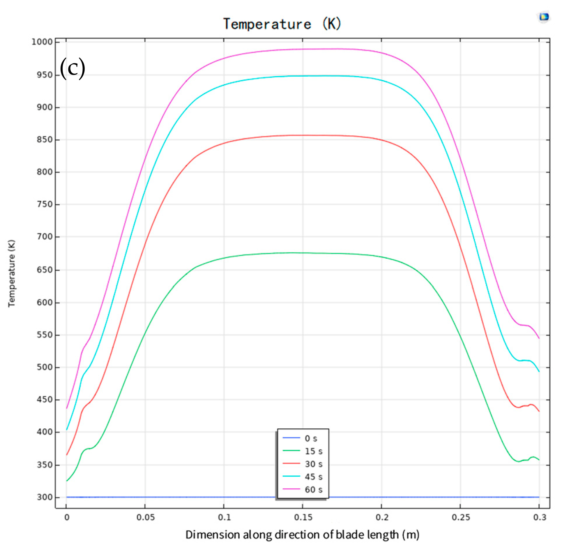
Figure 12 shows the temperature distribution curve of the blade airfoil simulated with coils of different pitch arrangements. The x-axis value is the distance to the blade platform area along the blade length direction. The position where x = 0.15 m is the middle of the heating area. From the comparison of different curves in Figure 12, it can be seen that the temperature uniformity of the whole heating area was gradually improved as the pitch arrangement design changed from completely equal pitch to variable pitches (sparse in the middle and dense at both ends). In the curve of No.5 design, the temperature difference within the range from 0.15 ± 0.05 m in x axis was only about 10 K. While in the curve of No.3 and No.4 design, the temperature difference in the same region, i.e., the 0.15 ± 0.05 m region in the middle region of heating area, was up to 40 K and 25 K separately. The results showed that the axial temperature uniformity of the blade can be effectively improved by refining the pitch arrangement of multiple turns solenoid coil and the heating region meeting the laser DED process requirements can be significantly expanded within the same allowable range of temperature error.
Figure 12.
The temperature distribution along the direction of blade length for coil design with different variable-pitch arrangement: (a) No.3 design: 30-30-30-30-30-30-30 mm; (b) No.4 design: 26-28-33-36-33-28-26 mm; (c) No.5 design: 27-28-32-33-33-29-28 mm.
4. Experimental Validation
4.1. Experimental Setup for Validation
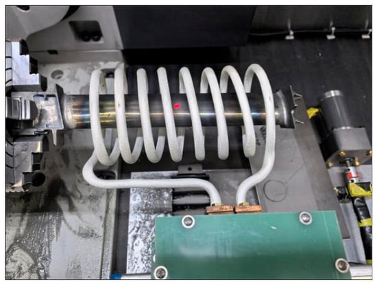
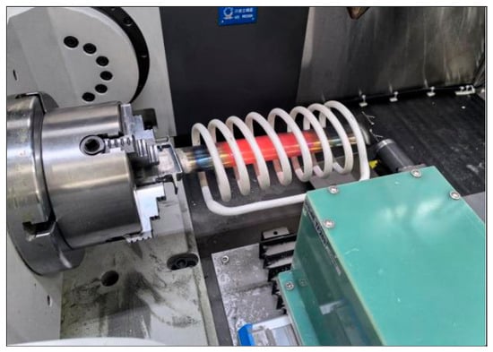
To verify the reliability of the simulation result and the effectiveness of the selected coil structure design, a high-frequency induction heating experimental setup was customized. Because the manufacturing and testing of all of the simulated coil designs would be costly, only the final selected variable-pitch elliptical solenoid coil based on No.5 design in Table 4 was fabricated and validated experimentally. As shown in Figure 13, it is installed on a movable guide rail so that the solenoid coil can slide out and move away from the blade surface very quickly after the airfoil is heated to the target temperature.
Figure 13.
The variable-pitch elliptical solenoid coil wrapped around the TiAl blade.
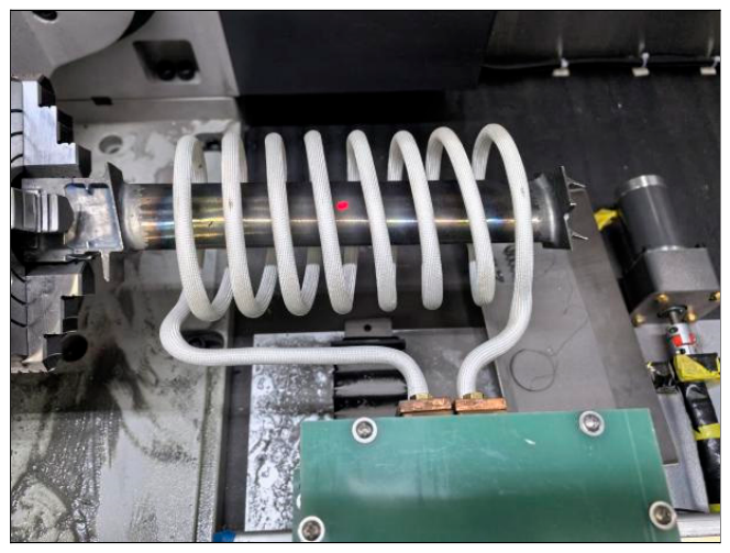
A closed-loop temperature control strategy was adopted in the test. The center point of the convex side of blade is chosen as the temperature sampling point for the closed-loop control. The heating power output is adjusted in real time through the feedback from temperature sensor, ensuring an appropriate temperature rising rate. The closed-loop heating system maintains the temperature constant after the target temperature of 1050 K is reached. In a complete laser DED process, the heating target may be set near 1100 K to compensate for the around 50 K temperature drop during the coil removal so that the temperature at the target location could be around 1050 K that is suitable for the laser DED. In the validation experiment, no subsequent coil-withdraw and laser DED step was performed and the blade could be wrapped by coil continuously, so 1050 K was used as the closed-loop set point to improve comparability with the simulation. A handheld infrared thermometer instead of a contact temperature sensor was used to remotely measure the temperature at different positions on the blade surface, avoiding the possible interference of the contact sensor on the measurement of the temperature distribution. Figure 14 shows the experimental setup with the solenoid and blade installed during the heating process. The induction heating power supply used in the experiment has a nominal alternating current frequency of 100 kHz, but it could be slightly deviated due to internal common mode inductance parameter errors. The maximum power of the physical power supply is 25 kW. In the experiment, the real-time power output is controlled by the closed-loop temperature control, which is different from the heating at a constant temperature rise rate in the simulation situation. In actual testing, the time for heating to the target temperature is about 50 s, which is close to the simulation data.
Figure 14.
Experimental setup during the heating process.
4.2. Temperature Measurement and Result Analysis
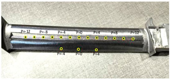
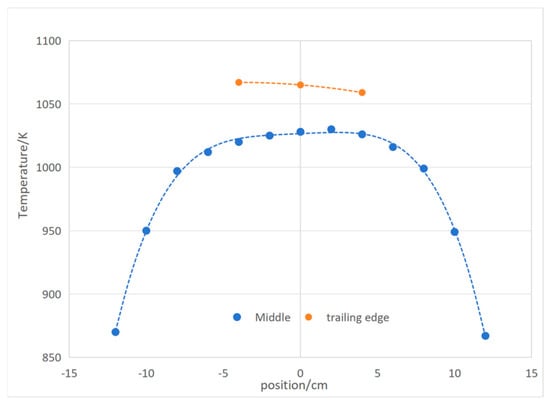
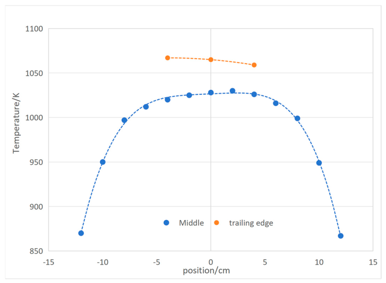
Taking the position near the center of the convex side as the coordinate zero position, the temperature sampling points are selected equidistant at 2 cm intervals along the length direction of blade from both sides; in addition, the temperature near the trailing edge was also measured at the positions of 0 cm and ±4 cm to evaluate the temperature uniformity along the length direction and the cross-section, respectively. The infrared pyrometer used a 1.6 μm short-wave probe, with a measurement range of 240–1400 °C, a resolution of 1 °C, and a spot diameter of about 4 mm. Before testing, its emissivity setting was calibrated using a 45XD TiAl sample with a thermocouple shallowly embedded near the measured surface; the emissivity was adjusted until the infrared reading was closest to the thermocouple temperature at red heat, approximately 800 °C. Figure 15 shows the temperature measurement points on the blade. The point marked with P = 0 is the above-mentioned coordinate zero position. The measured temperature data are shown in Table 5. Figure 16 shows the real distribution curve of the measured temperature on the convex side of the blade.
Figure 15.
The position of temperature measurement points on the convex side of blade airfoil.
Table 5.
The measured temperature data on the blade airfoil.
Figure 16.
The distribution curve of the measured temperature on convex side and trailing edge.
The experimental results showed that the measured temperature distribution curve of the blade is in good agreement with the simulation results of No.5 design in Table 4. As shown in Figure 16, the temperature was maintained stably at 1020–1030 K in the middle region (the range of 0 ± 5 cm in x-axis) of the blade airfoil and the temperature difference is only about 10 K, while the temperature of the area outside ± 8 cm which is closer to platform and tip shroud decreased rapidly compared with the middle region, which met the requirements of the temperature distribution with the characteristics of a steep drop at both ends and flat in the middle region during induction heating. The measured temperature difference between the trailing edge and the middle of the convex is slightly different from the simulation results, which was possibly caused by the limitation of the spot size of the measuring instrument. Because the sharp trailing-edge line was difficult to target directly, the experimental trailing-edge temperature was measured at a position about 3 mm away from the actual edge, as defined in Table 5. Additionally, the temperature measured is actually the average temperature in the spot. Therefore, the temperature difference between the temperature measured at the trailing edge and the middle of the blade convex is slightly less than the maximum temperature difference between the trailing edge and the center of blade airfoil in the simulation, but it is still basically consistent with the temperature difference in simulation results, which means it was valuable for engineering practice.
There is still an error between the actual measurement results and the simulation results in specific numerical values, which should be related to the limited accuracy of the infrared thermometer, the inaccurate measurement position, geometry and dimension accuracy of the coil and inaccurate positioning between the blade and coil, etc. In the future, quantitative analysis of these errors can be considered to further identify the specific patterns of error size and impact importance.
In terms of experimental repeatability, the same procedure was used to repeatedly heat from room temperature to the target temperature and conduct temperature testing. The heating time and temperature distribution are similar each time, but due to the limited stability of the clamped infrared thermometer, there will still be fluctuations of several degrees Celsius at the same position during each measurement. However, this does not affect the validity of the conclusion.
5. Conclusions
- Based on the theoretical analysis of electromagnetic heating induction, the finite element simulation model of electromagnetic-thermal coupling for induction heating of 45XD TiAl blade was built. Combined with the temperature-dependent material properties, the accurate simulation of induction heating process was realized. The simulation results are in engineering-level agreement with the experimental data, which verifies the reliability of the model and simulation.
- According to the demand on uniform heating of TiAl blade, the coil cross-sectional shape and pitch arrangement were determined as the selected key parameters based on the comparison among simulation of multiple designs. The elliptical coil can effectively solve the overheating problem of leading and trailing edges and reduce the temperature difference in the cross-section of the blade. The variable-pitch design characterized by “sparse in the middle and dense at both ends” can effectively compensate the axial temperature gradient and achieve uniform temperature rise in the heating area of the blade airfoil. The variable-pitch elliptical coil structure was validated to meet the preheating requirement for DED repair within the tested design set. The present work is limited by the inaccurate positioning of the infrared pyrometer, coil and blade, as well as the limited thermophysical properties provided by the blade manufacturer. Future work should include more detailed simulation-vs-experiment quantitative error analysis, repeatability analysis with accurate temperature measurement, as well as the validation in the actual laser DED after coil withdrawal.
Author Contributions
Conceptualization, Y.Z. and H.X.; Methodology, Y.Z. and H.X.; Validation, Y.Z. and P.D.; Investigation, Y.Z. and P.D.; Writing—original draft, Y.Z.; Writing—review & editing, H.X.; Project administration, H.X. All authors have read and agreed to the published version of the manuscript.
Funding
This research received no external funding.
Data Availability Statement
The original contributions presented in this study are included in the article. Further inquiries can be directed to the corresponding author.
Conflicts of Interest
The authors declare no conflicts of interest.
References
- Kim, Y.W.; Dimiduk, D.M. Progress in the understanding of gamma titanium aluminides. JOM 1991, 43, 40–47. [Google Scholar] [CrossRef] [Scilit]
- James, D.W.; Moon, D.M. The martensitic transformation in titanium binary alloys and its effect on mechanical properties. In The Science, Technology and Application of Titanium; Jaffee, R.I., Promisel, N.E., Eds.; Pergamon: Oxford, UK, 1970; pp. 767–778. [Google Scholar]
- McAndrew, J.B.; Kessler, H.D. Ti-36 pct Al as a base for high-temperature alloys. JOM 1956, 8, 1348–1353. [Google Scholar] [CrossRef] [Scilit]
- Fan, H.; Dong, H.; Zhao, T.; Zhu, C.; Li, Y.; Liang, Y.; Wang, H.; Li, X. Research progress on the forming process of TiAl alloy blade components. J. Plast. Eng. 2024, 31, 1–13. (In Chinese) [Google Scholar]
- Yang, R. Advances and challenges of TiAl-based alloys. Acta Metall. Sin. 2015, 51, 129–147. (In Chinese) [Google Scholar]
- Natole, R. Gas turbine components determining repairability and innovations to refurbish parts. In Proceedings of the Gas Turbine Conference and Exhibition, Anaheim, CA, USA, 31 May–4 June 1987; The American Society of Mechanical Engineers: Park Ave, NY, USA, 1987. [Google Scholar]
- Ünal-Saewe, T.; Gahn, L.; Kittel, J.; Gasser, A.; Schleifenbaum, J.H. Process development for tip repair of complex-shaped turbine blades with IN718. Procedia Manuf. 2020, 47, 1050–1057. [Google Scholar] [CrossRef] [Scilit]
- Liu, R.; Wang, Z.; Sparks, T.; Liou, F.; Newkirk, J. Aerospace applications of laser additive manufacturing. In Laser Additive Manufacturing: Materials, Design, Technologies, and Applications; Woodhead Publishing: Cambridge, UK, 2017; pp. 351–371. [Google Scholar]
- Wang, M.S.; Du, Y.L. Research progress of additive manufacturing of TiAl alloys. Acta Aeronaut. Astronaut. Sin. 2021, 42, 625263. (In Chinese) [Google Scholar]
- Rittinghaus, S.K.; Schmelzer, J.; Rackel, M.W.; Hemes, S.; Vogelpoth, A.; Hecht, U.; Weisheit, A. Direct energy deposition of TiAl for hybrid manufacturing and repair of turbine blades. Materials 2020, 13, 4392. [Google Scholar] [CrossRef] [Scilit]
- Appel, F.; Wagner, R. Microstructure and deformation of two-phase γ-titanium aluminides. Mater. Sci. Eng. R 1998, 22, 187–268. [Google Scholar] [CrossRef] [Scilit]
- Wang, J.W.; Luo, Q.; Wang, H.M.; Wu, Y.; Cheng, X.; Tang, H.B. Microstructure characteristics and failure mechanisms of Ti-48Al-2Nb-2Cr titanium aluminide intermetallic alloy fabricated by directed energy deposition technique. Addit. Manuf. 2020, 32, 101007. [Google Scholar] [CrossRef] [Scilit]
- Zinn, S.; Semiatin, S.L. Elements of Induction Heating: Design, Control, and Applications; ASM International: Metals Park, OH, USA, 1988. [Google Scholar]
- Chiang, M.F.; Chen, C. Induction-assisted laser welding of IN-738 nickel-base superalloy. Mater. Chem. Phys. 2009, 114, 415–419. [Google Scholar] [CrossRef] [Scilit]
- Li, Y. Induction heating for plastic deformation processing of titanium and titanium alloys (Part 1). Mach. Met. Form. 2016, 11, 31–36. (In Chinese) [Google Scholar]
- Huo, S.; Yan, Q.; Gao, X. Influence of induction heating coil parameters on temperature field of engine blade. Hot Work. Technol. 2018, 47, 70–74. [Google Scholar]
- Choubey, R.K.; Patil, M.; Jain, P.K. Tailoring coil geometry for achieving uniform heating through coil shape topology optimization for induction heating-based metal wire additive manufacturing. Rapid Prototyp. J. 2025, 31, 327–343. [Google Scholar] [CrossRef] [Scilit]
- Jiang, Y.; Zhang, D.; Qian, Y.; Wang, T. Numerical simulation and experimental validation of the induction heating process for slotted high-strength steel plates. Mater. Rep. 2025, 39, 1–13. (In Chinese) [Google Scholar]
- Cui, B.; Liu, W.; Bian, H. Influence of substrate preheating on the formation of cracks and microstructure in Ti-48Al-2Cr-2Nb alloy via laser directed energy deposition. Mater. Trans. 2024, 65, 597–602. [Google Scholar] [CrossRef] [Scilit]
- Lucia, O.; Maussion, P.; Dede, E.J.; Burdio, J.M. Induction heating technology and its applications: Past developments, current technology, and future challenges. IEEE Trans. Ind. Electron. 2014, 61, 2509–2520. [Google Scholar] [CrossRef] [Scilit]
- Huang, M.-S.; Huang, Y.-L. Effect of multi-layered induction coils on efficiency and uniformity of surface heating. Int. J. Heat. Mass. Transf. 2010, 53, 2414–2423. [Google Scholar] [CrossRef] [Scilit]
- Nian, S.C.; Tsai, S.W.; Huang, M.S.; Huang, R.C.; Chen, C.H. Key parameters and optimal design of a single-layered induction coil for external rapid mold surface heating. Int. Commun. Heat. Mass. Transf. 2014, 57, 109–117. [Google Scholar] [CrossRef] [Scilit]
- Xu, Y.; Leonhardt, A.; Birnbaum, P.; Gruner, J.; Kunke, A.; Clausmeyer, T. Design and optimization of induction coil for improved temperature uniformity in fast heating of sheet metal. Discov. Mech. Eng. 2026, 5, 65. [Google Scholar] [CrossRef] [Scilit]
- Davies, E.J. Conduction and Induction Heating; Peter Peregrinus Ltd.: London, UK, 1990. [Google Scholar]
- Rudnev, V.; Loveless, D.; Cook, R. Handbook of Induction Heating, 2nd ed.; CRC Press: Boca Raton, FL, USA, 2017. [Google Scholar]
- Kirtley, J.L. 6.061 Introduction to Electric Power Systems, Chapter 8: Electromagnetic Forces and Loss Mechanisms; MIT OpenCourseWare, Massachusetts Institute of Technology: Cambridge, MA, USA, 2011; Available online: https://ocw.mit.edu/courses/6-061-introduction-to-electric-power-systems-spring-2011/ (accessed on 10 May 2026).
- Peters, S.; Perez, M.; Blackwell, P. Integrating HIP and homogenisation heat treatment and its effect on the workability of a conventional peritectic TiAl alloy. Intermetallics 2023, 158, 107884. [Google Scholar] [CrossRef] [Scilit]

Disclaimer/Publisher’s Note: The statements, opinions and data contained in all publications are solely those of the individual author(s) and contributor(s) and not of MDPI and/or the editor(s). MDPI and/or the editor(s) disclaim responsibility for any injury to people or property resulting from any ideas, methods, instructions or products referred to in the content. |
© 2026 by the authors. Licensee MDPI, Basel, Switzerland. This article is an open access article distributed under the terms and conditions of the Creative Commons Attribution (CC BY) license.