


Abstract
Sulfur-containing medium-carbon microalloyed steel blooms are widely used for high-load automotive components, and reducing surface defects is important for improving product yield and lowering downstream processing costs. To address surface defects such as star cracks and microcracks in the continuous casting of these steel blooms, this study redesigned the mold flux on the basis of the steel’s solidification characteristics and crack susceptibility and carried out a twin-strand industrial comparative casting trial. Thermodynamic and thermophysical analyses indicated that the relatively high contents of S, Mn, and Ti/N in the steel promoted the precipitation of MnS and TiN–MnS complex inclusions along grain boundaries, severely weakening grain boundary cohesion. Meanwhile, the high specific heat capacity and low thermal conductivity further intensified thermal stress concentration in the solidifying shell, rendering the steel highly susceptible to cracking. Evaluation of the originally used mold flux (Flux A) revealed that its high melting temperature (1189 °C), long melting time (106 s), high break temperature (1170 °C), and poor crystallization behavior resulted in an excessively thin liquid slag layer (<5 mm) within the mold, making it difficult to provide adequate lubrication and stable heat transfer; these were key external factors inducing surface defects. Accordingly, the optimized mold flux (Flux B) was designed and prepared by increasing the basicity from 0.95 to 1.1, raising the Al2O3 content from 9.48% to 11.16%, increasing the F content from 4.93% to 5.58%, and reducing the carbon content from 13.85% to 6.97%. The rheological and crystallization properties of the flux were optimized in a coordinated manner, allowing uniform heat transfer through the crystalline slag layer while maintaining adequate lubrication. Industrial comparative trials demonstrated that Flux B stabilized the liquid slag layer at 8–10 mm, increased slag consumption to 0.56 kg/t, and significantly reduced surface defects such as star cracks and microcracks on blooms. The ultrasonic testing acceptance rate for rolled products increased to 98.6%, thereby meeting stringent quality requirements for the continuous casting of sulfur-containing, medium-carbon, microalloyed steel blooms.
1. Introduction
Sulfur-containing, medium-carbon microalloyed steel is an important non-quenched-and-tempered steel grade that is strengthened and toughened through V/Ti microalloying and sulfur control. It is widely used in high-load automotive drivetrain components such as crankshafts, connecting rods, and steering knuckles [1,2]. However, the relatively high sulfur content (0.045–0.065 wt.%), together with the multicomponent microalloying design involving Mn and Ti, significantly increases crack susceptibility during solidification, making bloom surfaces prone to defects such as star cracks and thereby severely compromising process stability and product yield [3,4].
The high crack susceptibility of this steel originates from its characteristic solidification precipitation behavior. Thermodynamic calculations and experimental studies have shown that the pronounced enrichment of Mn and S in the residual interdendritic liquid promotes the extensive precipitation of MnS along austenite grain boundaries [5,6,7,8]. In addition, because this steel contains Ti and a relatively high N content, TiN precipitates at higher temperatures and serves as a heterogeneous nucleation site for subsequent MnS precipitation, forming TiN–MnS composite inclusions along grain boundaries [9,10,11]. These intergranular inclusions directly disrupt grain-boundary cohesion, leading to grain-boundary embrittlement. Meanwhile, MnS precipitation can also induce the formation of manganese-depleted zones (MDZs) on both sides of grain boundaries, resulting in microstructural heterogeneity and further reducing local strength and ductility [12,13]. The coupled effects of grain-boundary embrittlement and microstructural heterogeneity deteriorate the high-temperature ductility of the steel and broaden its high-temperature brittle range, thereby markedly increasing its susceptibility to hot cracking [14,15,16,17,18]. Xing systematically analyzed the initiation and propagation of surface microcracks in sulfur-containing medium-carbon microalloyed steel blooms. He confirmed that these cracks are initiated by large MnS inclusions and propagate along austenite grain boundaries, and further pointed out that inadequate mold flux lubrication and non-uniform heat transfer in the mold play important roles in crack formation [19]. Therefore, during continuous casting, it is necessary to appropriately control lubrication and heat transfer conditions in the mold to alleviate the thermal and frictional stresses acting on the bloom surface.
Bloom continuous casting is an important route for producing this type of high-strength, high-toughness non-quenched-and-tempered steel. Compared with high-speed slab or thin-slab casting, the inherently low casting speed of blooms (typically 0.4–0.7 m/min) prolongs the residence time of the initial shell in the mold, thereby amplifying the effects of heat-flux fluctuations and transverse heat-flux non-uniformity on uniform shell growth [20,21]. In addition, bloom casting often employs a straight-bore submerged entry nozzle (SEN), which causes deep jet penetration, sluggish meniscus renewal, and insufficient heat input in the meniscus region. This hinders rapid melting and uniform spreading of mold flux, and also increases the risk of inadequate lubrication and local sticking [22]. These process characteristics further aggravate non-uniform shell growth and thermal stress concentration, making surface crack control a long-standing quality bottleneck in bloom continuous casting [23,24]. Therefore, as the key interfacial material governing lubrication and heat transfer in the mold, the mold flux should be designed to provide both stable lubrication and moderate crystallization: it should maintain a continuous liquid slag film while forming a crystalline slag layer to increase thermal resistance and homogenize heat flux, thereby suppressing non-uniform shell growth and thermal stress concentration [25,26,27,28,29]. For the highly crack-sensitive steel investigated here, under the combined conditions of a large bloom section and low heat flux, simultaneous control of lubrication and heat transfer is the core objective of mold flux design [30,31].
Existing studies have shown that mold flux performance can be tailored by adjusting basicity, CaF2, Al2O3, alkali metal oxides, and carbonaceous materials, thereby modifying its melting behavior, viscosity, and crystallization characteristics [32,33,34]. Considerable progress has been made in slab and billet continuous casting, and it is widely accepted that mold flux design should strike a balance between lubrication and heat-transfer control [33,35]. However, for the continuous casting of sulfur-containing medium-carbon microalloyed steel blooms, the combined effects of the steel’s high crack susceptibility and the process conditions of a large bloom section, low casting speed, and low heat flux impose more stringent requirements on mold flux performance, particularly in terms of the rapid formation of a stable liquid slag layer, the maintenance of continuous lubrication by the slag film, and uniform heat transfer in the middle and lower regions of the mold [36]. Most existing studies have focused on analyses of crack formation mechanisms or on empirical adjustments of mold flux compositions [19,35,36]. However, the relationship among steel solidification characteristics, bloom casting process constraints, mold flux property requirements, compositional design, and industrial surface-quality improvement has not been sufficiently established.
Therefore, this study conducts a systematic investigation into surface defects, including star cracks, depressions, and slag pits, on sulfur-containing medium-carbon microalloyed steel blooms. First, thermodynamic calculations are combined with defect characterization to clarify the intrinsic relationship between the steel’s solidification characteristics and the formation of surface defects. Second, in view of the characteristics of bloom continuous casting, the main deficiencies of the originally used mold flux (hereinafter referred to as Flux A) are analyzed, and, based on the steel’s solidification characteristics and crack susceptibility, the performance requirements and compositional adjustment strategy of the mold flux are systematically established. The novelty of this work lies in establishing a steel-grade-specific mold flux optimization strategy by linking the solidification and precipitation characteristics of the investigated steel with the melting, lubrication, and heat-transfer requirements of bloom continuous casting. Finally, the optimized flux is prepared using industrial raw materials through a spray-drying granulation process and validated by a two-strand industrial comparative casting trial in terms of liquid slag layer stability, heat-transfer control, and bloom surface quality. Together, these efforts form a complete route from laboratory formulation to plant-scale application and provide a scientific basis for connecting steel-specific crack susceptibility with mold flux property design in bloom continuous casting.
2. Materials and Methods
2.1. Surface Defect Characterization
2.1.1. Steel Grade and Bloom Continuous Casting Parameters
The steel investigated in this study was a sulfur-containing medium-carbon microalloyed steel produced at a steel plant. Its chemical composition is given in Table 1, where the composition ranges were taken from the plant’s internal specifications, and the target composition represents the average of multiple heats. The bloom cross-section was 300 × 340 mm, and the blooms were primarily rolled into round bars with diameters of 60–180 mm. The production route was electric arc furnace (EAF) → ladle furnace (LF) → vacuum degassing (VD) → bloom continuous casting → off-line slow cooling or hot charging → continuous rolling → stack cooling.
Table 1.
Chemical composition range and target composition of the investigated steel (wt.%).
The continuous casting equipment and process parameters are summarized in Table 2; all values were obtained from on-site records during stable-state casting. These parameters were maintained constant during the comparative casting trials to ensure a consistent basis for evaluating the two mold fluxes.
Table 2.
Main process parameters of bloom continuous casting.
2.1.2. Methods for Surface Defect Characterization
To characterize the morphologies of surface cracks on blooms, specimens were extracted from representative defect regions by wire electrical discharge machining, and metallographic sections perpendicular to the surface were prepared. The samples were mounted, progressively ground and polished, and then etched with 4% nital to reveal the microstructure. Crack morphologies and the surrounding microstructures were examined using an optical microscope (DM2700MRL, Leica, Wetzlar, Germany). The morphology in the vicinity of the cracks was further examined by scanning electron microscopy (SEM, EVO18, Zeiss, Oberkochen, Germany), and point chemical analysis was performed using energy-dispersive X-ray spectroscopy (EDS).
2.2. Methods for Calculation of Solidification Behavior and Thermophysical Properties
To elucidate the solidification behavior of the investigated steel, Thermo-Calc was used to calculate the solidification path and the precipitation sequence of inclusions under equilibrium conditions. The calculations were conducted using the target composition listed in Table 1, over the temperature range from the liquidus to 600 °C, at a total pressure of 1 atm.
Key thermophysical properties, including density, specific heat capacity, latent heat of solidification, and thermal conductivity, were further calculated under equilibrium conditions using JMatPro (v13.0) with the General Steel database to characterize trends in thermal contraction and heat transfer. To benchmark these properties, a multidimensional comparison framework was established that considers carbon content, strength grade, and degree of alloying. Q235 (low-carbon steel), 40# (medium-carbon structural steel), Q690 (high-strength low-alloy structural steel), 20CrMnTi (low-alloy carburizing gear steel), and T10 (high-carbon tool steel) were selected as reference steels (Table 3). This framework enables a systematic comparison of the investigated steel in terms of thermal contraction behavior, heat-capacity characteristics, and thermal conductivity, thereby providing a basis for discussing crack susceptibility and guiding subsequent mold flux design. The chemical compositions of the reference steels and the investigated steel are listed in Table 4.
Table 3.
Reference steels and rationale for comparison.
Table 4.
Chemical compositions of the reference steels and the investigated steel (wt.%).
2.3. Methods for Physicochemical Property Characterization of Mold Fluxes
The contents of the major oxides in the mold fluxes were determined using an X-ray fluorescence spectrometer (XRF, S4 Pioneer, Bruker AXS, Karlsruhe, Germany). The total carbon content was measured using a combustion–infrared carbon–sulfur analyzer. The fluorine (F) content was obtained from the supplier’s certificate of analysis (COA) and was not re-measured in this study.
The key physicochemical properties were characterized as follows:
- (1)
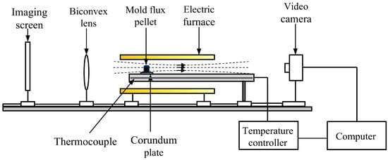
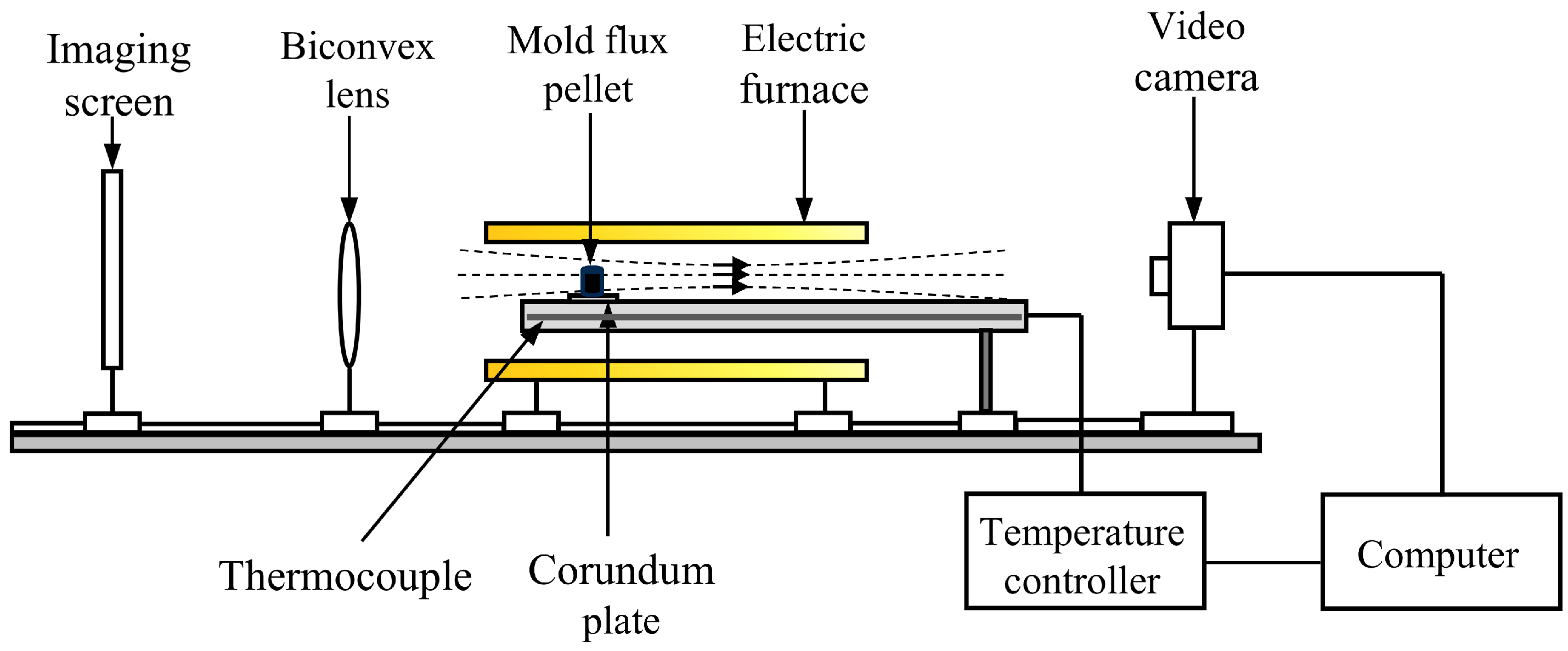
- The melting behavior of the mold flux was characterized using an LZ-III automatic slag melting characteristics tester, as illustrated in Figure 1. The mold flux was ground to 200 mesh and pressed into cylindrical pellets (φ3 mm × 3 mm). The pellets were heated at a rate of 15 °C/min, and morphological evolution was recorded using a high-temperature microscope. Using the deformation method, the temperatures corresponding to decreases in sample height to 75%, 50%, and 25% of the initial height were defined as the start-of-melting temperature (Ts), melting temperature (Th), and flow temperature (Tf), respectively. The melting time was defined as the time required for the pellet to change from the onset of softening to complete spreading on a corundum plate preheated to 1350 °C. Each test was repeated three times, and the average values of Th and the melting time were reported.Figure 1. Schematic diagram of the automatic tester for mold flux melting temperature and melting time.
- (2)
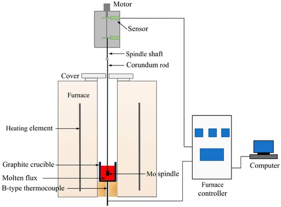
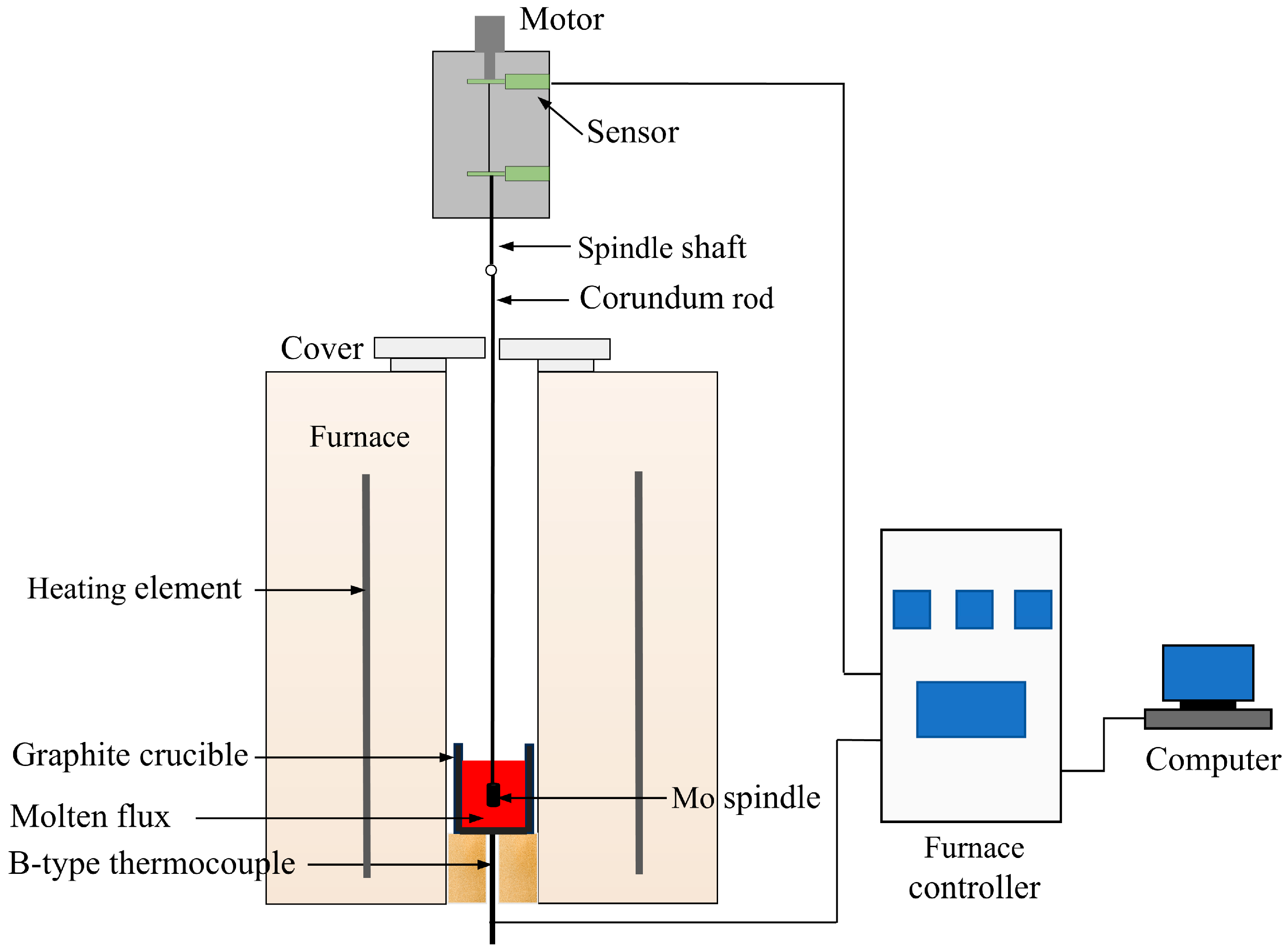
- A Brookfield high-temperature rotational viscometer was employed to obtain the viscosity–temperature curve and the break temperature of the mold flux, as schematically shown in Figure 2. Approximately 300 g of the decarburized mold flux was charged into a graphite crucible. The sample was heated in a MoSi2 furnace under high-purity argon (purity > 99.999%, 1.5 L/min) at 3 °C/min to 1400 °C and held for 10 min to ensure chemical homogeneity of the molten slag. A Mo spindle was then immersed along the central axis of the graphite crucible, with the spindle tip positioned 10 mm above the crucible bottom. Viscosity was measured at a constant rotational speed of 200 rpm while continuously cooling at 5 °C/min to obtain the viscosity–temperature curve. The break temperature (Tbr) was defined as the temperature at the inflection point on the viscosity–temperature curve where viscosity began to increase sharply with decreasing temperature. Measurements were terminated when the viscosity approached 3.5 Pa·s.Figure 2. Schematic of the high-temperature rotational viscometer setup.
- (3)
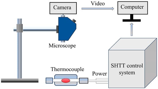
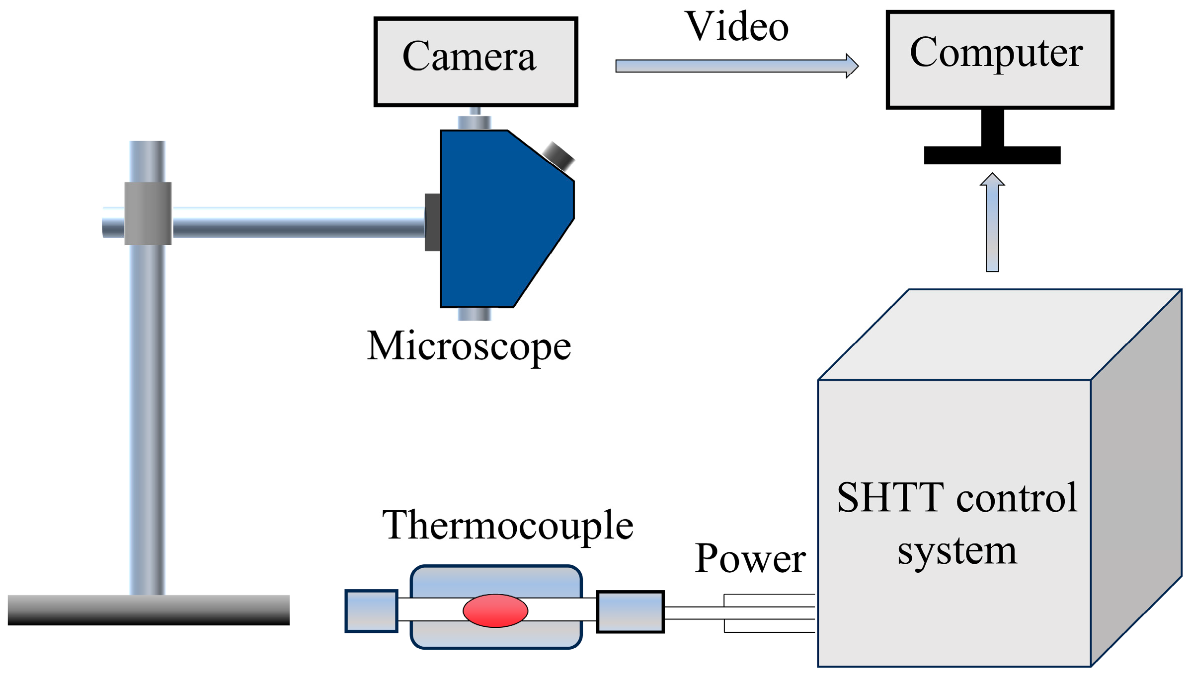
- The crystallization behavior of the mold flux was investigated using a single hot thermocouple technique (SHTT) apparatus (Model SHTT-II), as illustrated in Figure 3. Sample preparation was conducted as follows. First, the decarburized mold flux was ground to 200 mesh, mixed with anhydrous ethanol to form a paste, and uniformly coated onto the junction of a U-shaped Pt–Rh thermocouple. The sample was then heated to 1500 °C at 10 °C/s and held for 150 s to remove bubbles and ensure compositional homogenization of the molten slag. Subsequently, the melt was cooled at different cooling rates, and the area fraction of crystalline phases was quantified from recorded images using image-processing software. The temperature corresponding to a crystallization fraction of 5% was defined as the crystallization start temperature, whereas that corresponding to 95% crystallization was defined as the crystallization completion temperature. Each condition was tested three times, and the mean values were reported.Figure 3. Schematic of the SHTT apparatus.
2.4. Spray Drying Preparation of the Optimized Mold Flux and Industrial Trials
2.4.1. Spray Drying Preparation of the Optimized Mold Flux
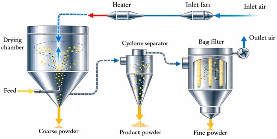
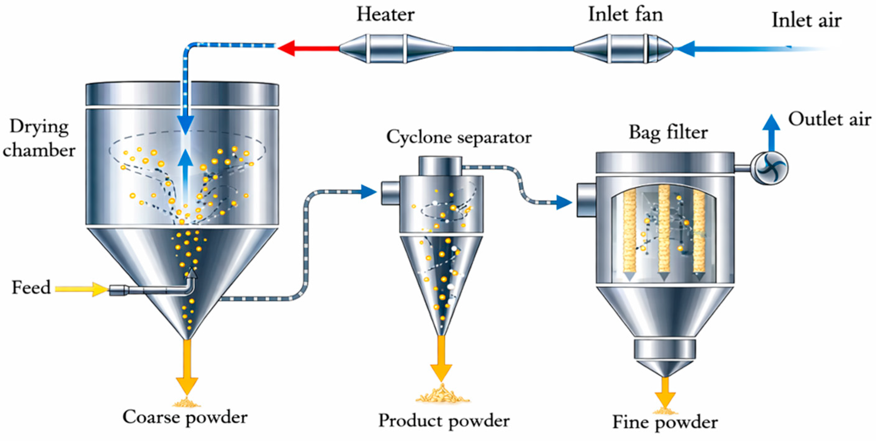
Based on the laboratory-optimized formulation (Flux B-Lab), the optimized mold flux was prepared in batches using an experimental spray-drying granulation process, as schematically shown in Figure 4. The main raw materials included limestone, wollastonite, bauxite, fluorite, carbon black, and graphite, which were weighed accurately to match the target chemical composition. The dry powders were mixed with deionized water, and a binder (yellow dextrin, 2 wt.%) and a dispersant (sodium methylnaphthalene sulfonate, MF, 0.5 wt.%) were added while stirring. The mixture was then ball-milled in a roller ball mill for 4 h to obtain a homogeneous slurry with a solid content of approximately 40–45%. The slurry was pressurized to 0.15 MPa by a plunger pump and fed into the drying tower through a pressure-atomizing nozzle. Hot air (inlet temperature: 300 °C) entered through a top distributor and contacted the atomized droplets in the drying chamber, thereby enabling rapid drying and the formation of mold flux granules. The dried granules were collected using a cyclone separator, with an outlet temperature of 120 °C. After drying, the granulated powders were classified according to particle size. Granules within the target particle-size fraction were collected as product powder, whereas oversized coarse powder and undersized fine powder were returned to the slurry preparation step for further processing.
Figure 4.
Schematic diagram of the spray-drying granulation process for mold flux.
2.4.2. Industrial Trials and Evaluation
To verify the industrial applicability of the optimized mold flux (Flux B), a twin-strand comparative casting trial was conducted at the plant’s No. 2 continuous caster. The trial was performed during Heats 2 and 3. Strand 1 was cast using Flux B, whereas Strand 2 continued to use the original Flux A as the reference. Manual flux feeding was adopted for both strands. The trial primarily evaluated the thickness of the liquid slag layer in the mold, slag consumption, and bloom surface quality.
3. Results and Discussion
3.1. Analysis of Bloom Surface Defects
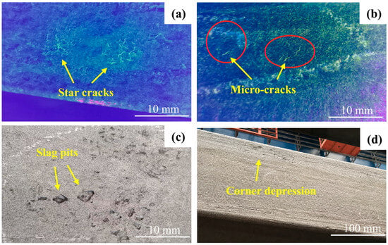
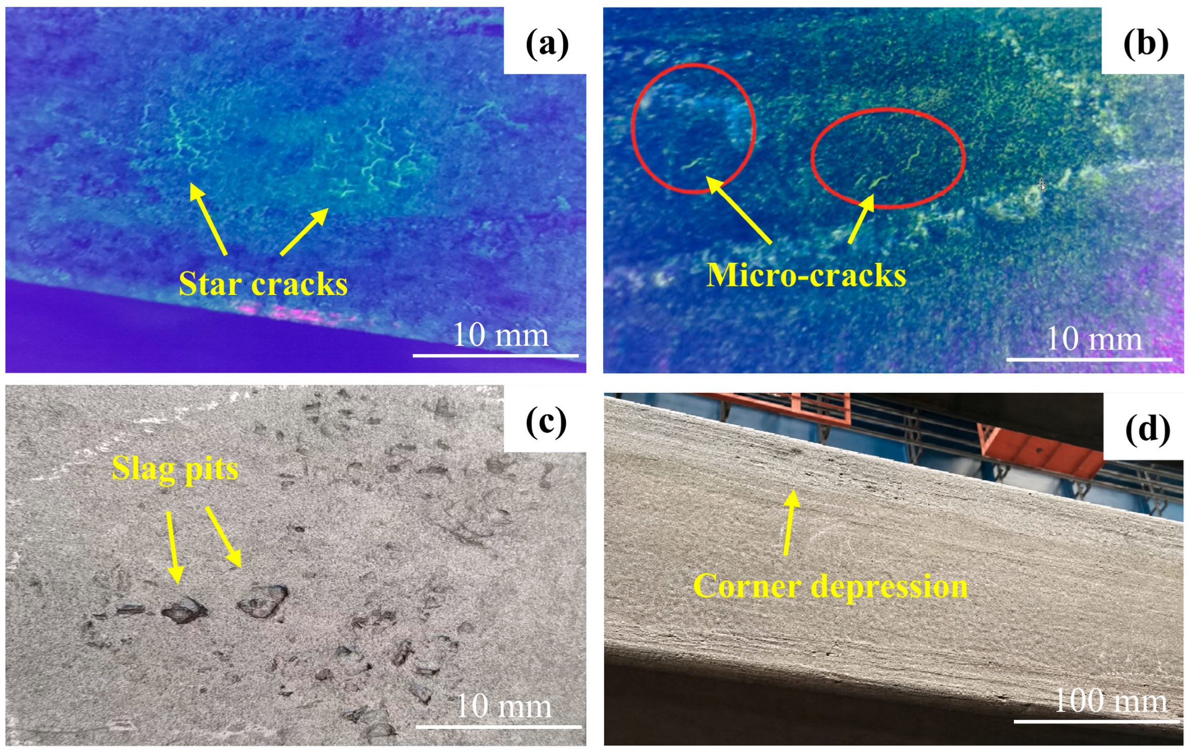
Pickling and magnetic particle inspection revealed numerous defects in the corner region of the bloom surface, as shown in Figure 5. Representative bloom samples with typical surface defects were collected from the industrial production line before mold flux optimization. Figure 5a,b show star cracks and transverse microcracks, respectively, in the bloom corner, and their distribution is highly irregular. Figure 5c shows slag pits in the corner region, with depths of approximately 1.3–1.5 mm and widths of approximately 2–3 mm. Figure 5d shows corner depression and blurred oscillation marks on the bloom surface.
Figure 5.
Macroscopic appearance of typical surface defects on the bloom surface: (a) star cracks; (b) micro-cracks; (c) slag pits; (d) corner depression.
Previous studies have shown that, because of the intensified two-dimensional cooling in the corner region, an air gap tends to form earlier, resulting in a relatively higher shell temperature there and promoting abnormal coarsening of austenite grains [37,38,39]. Coarse austenite grains can markedly reduce the high-temperature ductility and grain-boundary cohesion of steel, constituting a key factor for the initiation of microcracks. In addition, defects such as depressions and blurred oscillation marks are often observed around cracks, indicating inadequate mold lubrication. The thickness of the liquid slag layer was measured using the steel-wire method and found to be less than 5 mm. An excessively thin and unstable liquid slag layer can lead to an uneven distribution, or even local loss, of the liquid slag film, thereby causing intermittent lubrication, sticking, and non-uniform heat transfer. Consequently, the resulting frictional and thermal stresses concentrate at weak regions of the thin shell, ultimately promoting crack initiation and propagation.
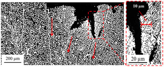
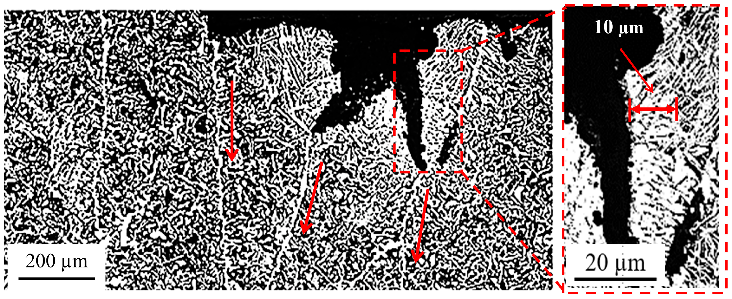
A representative crack was selected for detailed metallographic examination, and the results are presented in Figure 6. The crack extends approximately 0.6–0.8 mm from the bloom surface into the matrix and bifurcates at a depth of ~0.2 mm. Relative to the unaffected matrix, the region adjacent to the crack exhibits a markedly elevated fraction of proeutectoid ferrite and a corresponding reduction in pearlite, resulting in a pronounced decarburized layer along both crack flanks. The decarburized layer is approximately 10 μm thick and can locally reach up to 30 μm along the crack flanks, indicating that the crack most likely formed during the high-temperature stage within the mold. Moreover, the crack propagation path follows the proeutectoid ferrite network decorating the prior austenite grain boundaries (indicated by red arrows in Figure 6), exhibiting the classic metallographic signature of intergranular cracking. This intergranular cracking behavior is consistent with the mechanism of grain-boundary weakening caused by the precipitation of MnS and TiN–MnS complex inclusions along prior austenite grain boundaries, which has been experimentally documented for the same steel grade [19,40]. Together, these findings indicate that grain-boundary weakening played a critical role in both crack initiation and propagation.
Figure 6.
Microstructural characteristics of a surface crack on the bloom.
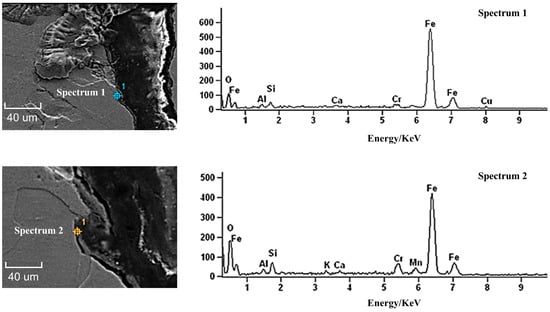
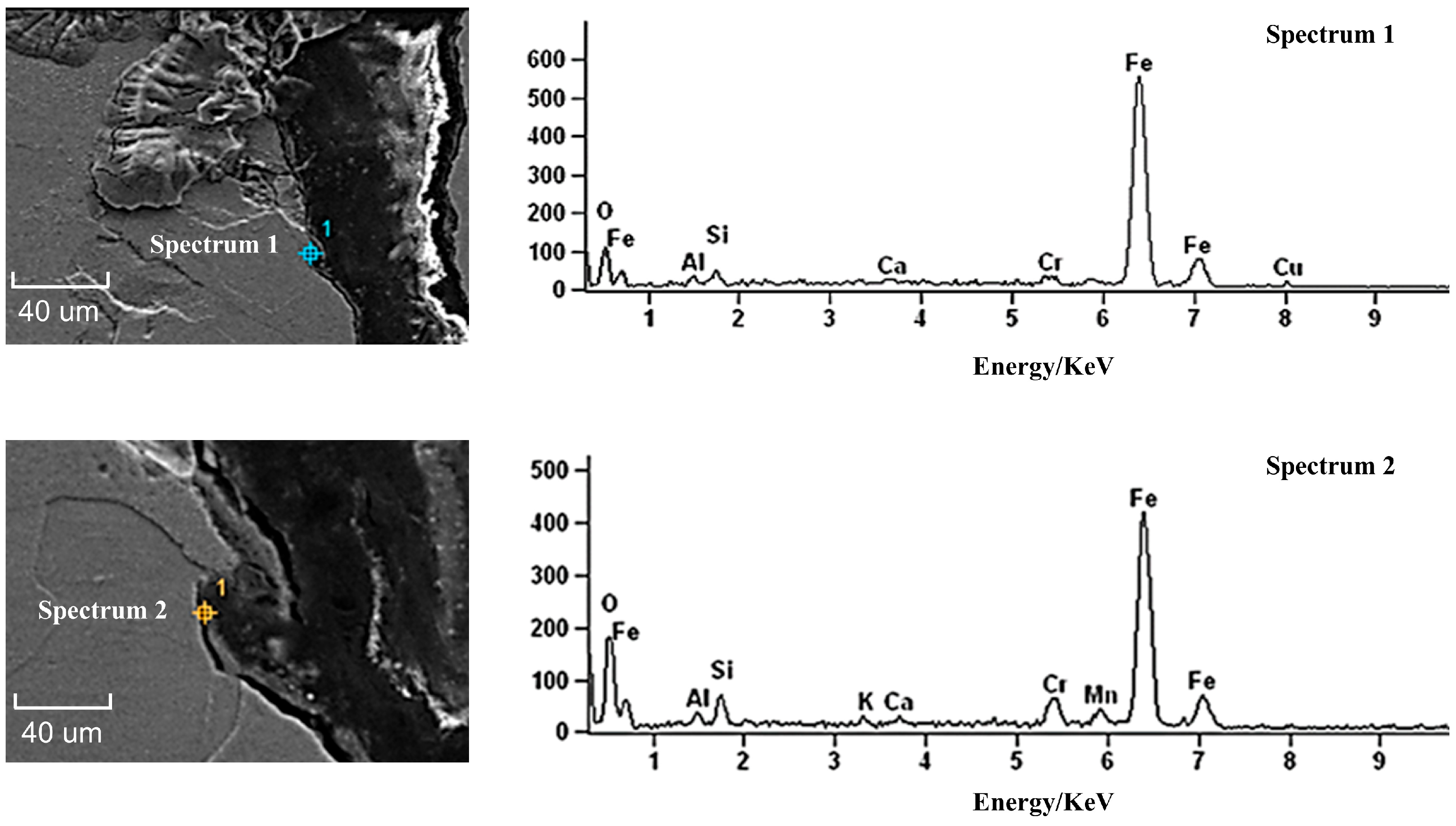
Energy-dispersive X-ray spectroscopy (EDS) was employed to analyze the elemental composition in the vicinity of the crack, as shown in Figure 7. The point EDS results revealed pronounced enrichment of Ca, Si, Al, and K in the crack region, indicating that the crack most likely formed in the mold and was accompanied by local infiltration of liquid mold flux [41,42].
Figure 7.
EDS spectral analysis in the vicinity of the crack.
3.2. Solidification Characteristics and Crack Sensitivity of the Sulfur-Containing Medium-Carbon Microalloyed Steel
3.2.1. Thermodynamic Analysis of Solidification Phase Transformations and Inclusion Precipitation
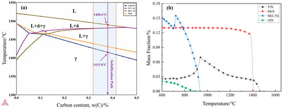
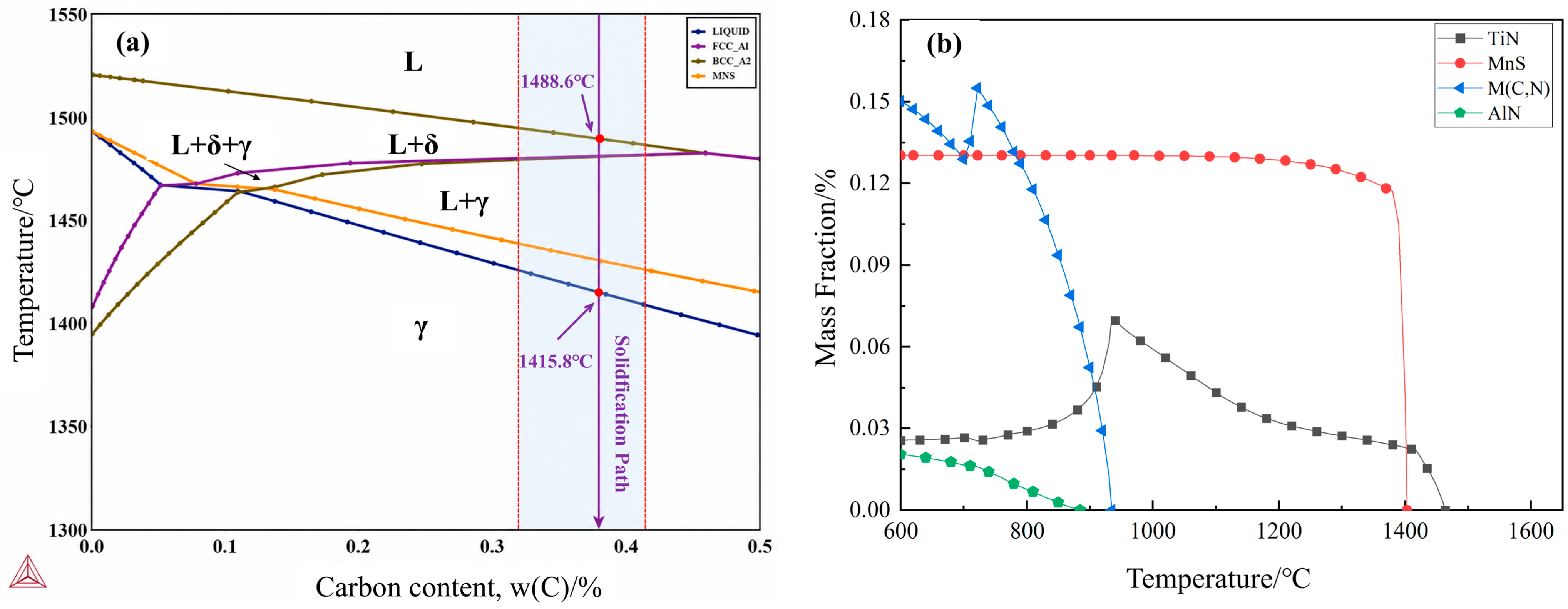
Thermo-Calc was employed to analyze the equilibrium solidification path and the inclusion precipitation sequence of the sulfur-containing medium-carbon microalloyed steel, as shown in Figure 8. The precipitation calculation was performed down to 600 °C, while the discussion focuses on precipitation above 1000 °C, which is more relevant to bloom solidification and crack formation in the mold.
Figure 8.
Equilibrium solidification path and inclusion precipitation sequence of the sulfur-containing medium-carbon microalloyed steel: (a) Equilibrium solidification path; (b) Inclusion precipitation sequence.
As shown in Figure 8a, the solidification path of the sulfur-containing medium-carbon microalloyed steel follows L → L + δ → L + γ + δ → L + γ → γ, with a liquidus temperature of approximately 1489 °C and a solidus temperature of approximately 1416 °C, yielding a solidification interval of about 73 °C. Based on the Fe–C phase diagram, the steel’s carbon content (0.38 wt.%) falls within the hyperperitectic range, characteristic of hyperperitectic solidification. δ-ferrite precipitates over a narrow temperature interval of approximately 6 °C (from ~1489 °C to ~1483 °C), indicating that only a limited fraction of δ-ferrite forms. Moreover, the peritectic reaction (L + δ → γ) occurs at a relatively low solid-fraction stage, where sufficient liquid remains; thus, liquid feeding can partially compensate for the volumetric shrinkage associated with the phase transformation [43,44].
Non-metallic inclusions in molten steel tend to undergo morphological evolution during solidification, thereby exerting a critical influence on the surface quality of continuously cast products. As shown in Figure 8b, TiN first precipitates at approximately 1455 °C during solidification. Fine TiN particles can serve as heterogeneous nucleation sites for subsequent MnS precipitation, leading to the formation of core–shell TiN–MnS composite inclusions through overgrowth. According to the literature, the overall size of TiN–MnS composite inclusions can reach 3–5 μm. In interdendritic regions with severe sulfur segregation, these inclusions may further coarsen to >10 μm, thereby increasing the risk of grain-boundary embrittlement and crack sensitivity [40].
More importantly, the precipitation behavior of MnS is critical. MnS starts to precipitate at approximately 1430 °C; once nucleation occurs, its mass fraction increases rapidly and then approaches a stable level (≈0.13%), indicating a strong MnS precipitation tendency in this steel. The morphology and distribution of MnS can markedly affect crack sensitivity. First, an elevated sulfur content promotes the formation of chain-like or elongated MnS along austenite grain boundaries; such morphologies directly disrupt grain-boundary continuity and reduce the high-temperature ductility of steel [45]. Second, the interfacial bonding strength between MnS and the steel matrix is relatively weak, and interfacial debonding can readily occur under thermal or mechanical stresses, leading to the formation of microvoids [46,47]. Third, MnS precipitation may induce the formation of manganese-depleted zones (MDZs) on both sides of grain boundaries, where the local strength is significantly lower than that of the matrix; the resulting plastic mismatch tends to cause local stress concentration, thereby promoting the coalescence of these microvoids along embrittled grain boundaries into microcracks [48,49]. Finally, because of the pronounced difference in thermal expansion coefficients between MnS and the steel matrix, additional tensile stresses can be generated at the inclusion–matrix interface during continuous-casting cooling, which facilitates microcrack initiation and propagation [50].
In addition, thermodynamic calculations predict that V/Ti carbonitrides, denoted as M(C,N), precipitate mainly from approximately 1075 to 600 °C, reaching a maximum mass fraction of about 0.15%. AlN is predicted to precipitate progressively after ~1000 °C, with its mass fraction increasing slowly to approximately 0.02% as the temperature decreases. Because nitrogen is preferentially consumed by TiN, the overall amount of AlN precipitation is relatively limited.
In summary, the thermodynamic results indicate that this steel exhibits a strong tendency for MnS precipitation during solidification and may form composite inclusions such as TiN–MnS, which can significantly reduce austenite grain-boundary strength and high-temperature ductility. As a result, the cast bloom, particularly stress-concentrated regions such as corners, becomes highly sensitive to thermal and mechanical stresses, thereby increasing the likelihood of intergranular microcrack formation. Therefore, adequate mold lubrication and uniform heat transfer in the mold are critical external conditions for controlling surface defects in this steel.
3.2.2. Analysis of the Solidification-Related Thermophysical Properties of the Sulfur-Containing Medium-Carbon Microalloyed Steel
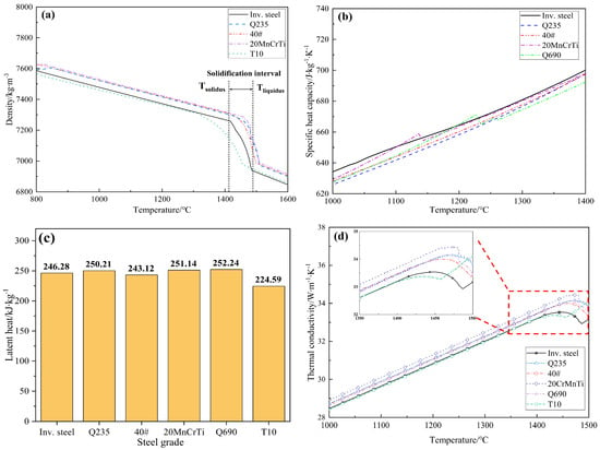
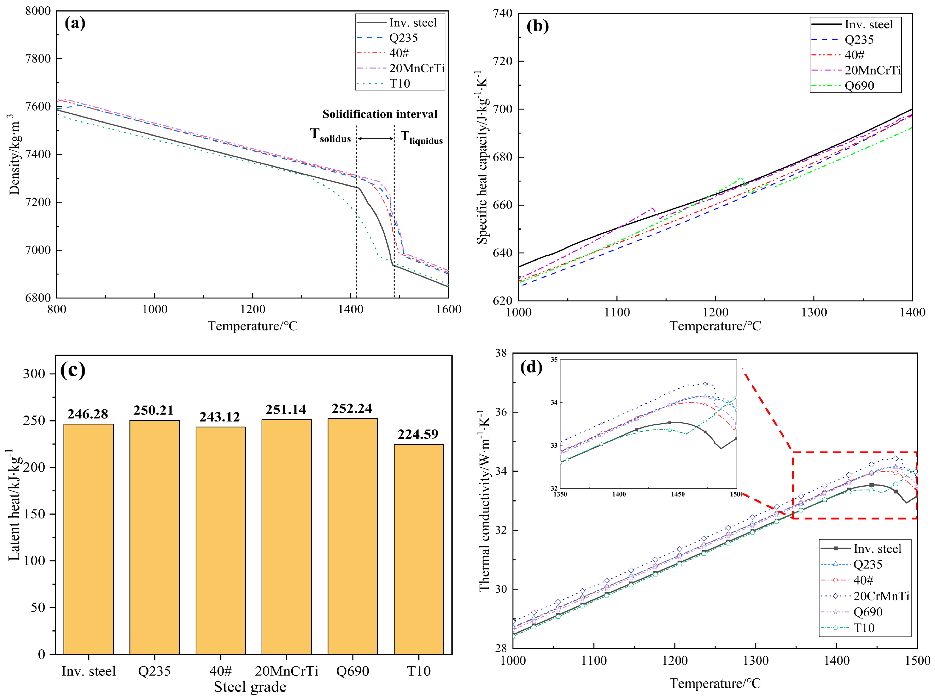
To elucidate the surface crack susceptibility of the sulfur-containing medium-carbon microalloyed steel, JMatPro was employed to analyze the key high-temperature thermophysical properties of the investigated steel and several reference grades (Q235, 40#, Q690, T10, and 20CrMnTi), including density, specific heat capacity, latent heat of solidification, and thermal conductivity, as shown in Figure 9.
Figure 9.
Comparison of thermophysical properties: (a) Density; (b) Specific heat capacity; (c) Latent heat of solidification; (d) Thermal conductivity.
As shown in Figure 9a, within the solidification temperature interval, the absolute value of the density–temperature slope for the investigated steel (|dρ/dT|) is 4.69 kg·m−3·K−1, which is higher than that of all the reference steels except 20CrMnTi. This indicates a stronger tendency for volumetric shrinkage under identical cooling conditions, thereby increasing the risk of non-uniform shell contraction and stress concentration.
Figure 9b shows that the investigated steel exhibits a generally higher specific heat capacity in the high-temperature range than the reference steels. Under identical mold cooling conditions, a higher specific heat capacity implies a slower cooling rate of the strand and a steeper temperature gradient at the solidification front, which can aggravate non-uniform shell growth and thermal stress concentration.
Although the latent heat of solidification of the investigated steel is comparable to that of the reference steels (Figure 9c), its thermal conductivity is markedly lower (Figure 9d), close to that of the high-carbon steel T10, which is known for its low thermal conductivity. The reduced thermal conductivity impedes rapid heat transfer and is unfavorable for homogenizing the shell temperature field.
In summary, the sulfur-containing medium-carbon microalloyed steel is prone to non-uniform shell growth, large local temperature gradients, and thermal stress concentration in the mold. Together with the aforementioned grain-boundary embrittlement caused by intergranular precipitation of MnS/TiN–MnS, these thermophysical characteristics contribute to the high surface crack susceptibility of the continuously cast bloom.
3.3. Process Characteristics of Bloom Continuous Casting
As summarized in Table 2, the investigated steel was produced by bloom continuous casting. Compared with high-speed slab or small-billet casting, bloom casting exhibits distinct characteristics in molten-steel flow, heat transfer, and lubrication, placing greater demands on mold flux performance. Therefore, this section identifies the mold-flux performance requirements imposed by these process characteristics and provides the basis for evaluating Flux A and optimizing Flux B in the following sections.
First, as listed in Table 2, bloom casting of the sulfur-containing medium-carbon microalloyed steel employs a straight-bore SEN with an immersion depth of 90–120 mm, which causes deep jet penetration, weak upper recirculation, and sluggish molten-steel renewal in the meniscus region, resulting in insufficient heat input. This flow pattern is unfavorable for rapid melting and uniform spreading of the mold flux, and it tends to produce a thin, non-uniform liquid slag layer. Based on the cooling-water temperature-rise method (i.e., estimating the average mold heat flux from the measured cooling-water flow rate and the temperature difference between the outlet and inlet water, ΔT_water), the average mold heat-flux density was estimated to be only 0.9 MW·m−2, which is not only close to the lower bound of conventional continuous casting (approximately 0.8–1.6 MW·m−2) but also slightly lower than that reported for wide-and-thick slab casting (approximately 1.1 MW·m−2) [51,52]. Such a low heat-flux density not only weakens the thermal driving force for flux melting but may also destabilize the liquid slag film at the shell–mold interface. Therefore, the mold flux is required to exhibit a higher melting rate so as to rapidly form and maintain a sufficiently thick liquid slag layer.
Second, owing to the large bloom cross-section (300 × 340 mm, Table 2), the temperature gradient between the surface and interior of the strand is more pronounced, and the initial shell is prone to higher thermal stresses [53]. In addition, the relatively high Si content reduces the thermal conductivity of the steel, while the elevated S content lowers high-temperature ductility by promoting MnS precipitation. These combined effects make thermal stresses more likely to concentrate at weakened grain boundaries, particularly in the corner region where the cooling intensity is higher. Consequently, the mold flux should possess an appropriate crystallization tendency to establish a stable and uniform thermal resistance in the middle and lower parts of the mold, thereby mitigating heat-flux fluctuations and suppressing thermal-stress concentration.
Third, the casting speed for this steel is 0.5–0.6 m·min−1, and the effective mold length is 800 mm (Table 2), corresponding to a residence time in the mold of approximately 80–96 s. Compared with high-speed slab or thin-slab casting, the mold flux remains in contact with the shell for a longer period. Therefore, inadequate lubrication or non-uniform heat transfer can persist over an extended duration, increasing the likelihood of surface defect formation.
Fourth, for the large bloom section of 300 mm × 340 mm (Table 2), maintaining a continuous and uniform liquid slag film over the shell–mold interface becomes more demanding, especially in the middle and lower parts of the mold. Therefore, the mold flux must have sufficient liquid slag supply capacity and should not have an excessively high break temperature. This ensures that the liquid slag maintains adequate fluidity in the lower part of the mold, thereby achieving full lubrication throughout the mold [27,54]. These requirements provide the basis for evaluating the limitations of Flux A and designing the optimized Flux B in the following sections.
3.4. Performance of the Original Mold Flux and Analysis of Surface Defect Formation
The chemical composition of the originally used mold flux (Flux A) for the continuous casting of sulfur-containing medium-carbon microalloyed steel blooms is listed in Table 5.
Table 5.
Chemical composition of Flux A (wt.%).
The measured properties of Flux A are summarized in Table 6. The crystallization behavior of Flux A was evaluated by SHTT. No crystalline phase was observed at different cooling rates (10, 1, 0.5, 0.1 °C/s), indicating a weak crystallization tendency.
Table 6.
Key performance parameters of Flux A.
As discussed in Section 3.2 and Section 3.3, the inherent solidification characteristics of the sulfur-containing medium-carbon microalloyed steel, together with the features of bloom continuous casting, render this steel highly susceptible to cracking. However, this intrinsic crack susceptibility still requires external triggering conditions. Deficiencies of Flux A in lubrication and heat-transfer control are the direct cause of frequent surface defects on the bloom, including star cracks, depressions, and slag pits.
First, the powder melting behavior and liquid slag supply capacity of Flux A are inadequate. The high melting temperature (1189 °C) and long melting time (106 s) of Flux A lead to a persistently thin liquid slag layer (≤5 mm), which is well below the recommended safe range of 8–15 mm for bloom continuous casting. An excessively thin and unstable liquid slag layer makes it difficult to form a uniform and continuous liquid slag film, and local interruption of lubrication may even occur, leading to direct friction between the shell and the mold and thereby inducing star cracks [55]. In addition, the high melting temperature and long melting time may be associated with the presence of high-melting-point particles in the mold flux; these particles can adhere to the initial shell and then be washed away by cooling water after the strand exits the mold, thereby directly forming slag pits on the bloom surface.
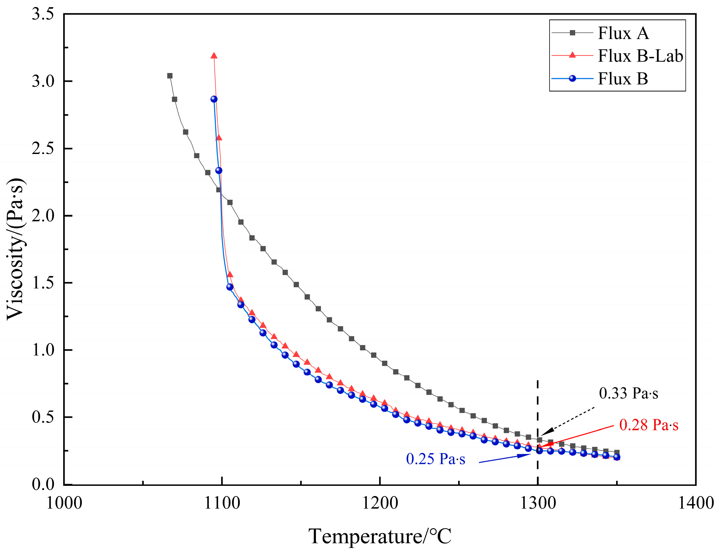
Second, the rheological properties of Flux A are unsatisfactory, resulting in poor lubrication performance. Under conditions of a thin liquid slag layer, the viscosity of Flux A (0.33 Pa·s) is relatively high, which is unfavorable for maintaining the uniformity of the liquid slag film. In addition, its high break temperature (1170 °C) means that the liquid slag film loses fluidity at relatively high temperatures, causing the middle and lower parts of the mold to enter a solid-friction-dominated regime prematurely. These combined effects impair the stability and continuity of lubrication in the middle and lower parts of the mold, thereby aggravating frictional stress concentration and increasing the likelihood of star crack formation.
Finally, the heat-transfer control capability of Flux A is insufficient. Flux A exhibits predominantly glassy solidification behavior, making it difficult to form a crystalline slag layer with stable thermal resistance in the middle and lower parts of the mold and thereby failing to stabilize heat flow. When the liquid slag film is thin and uneven, heat-flux non-uniformity and fluctuation become more pronounced, aggravating non-uniform shell growth and promoting local thermal stress concentration. Therefore, for such crack-sensitive steel grades, the crystallization behavior of the slag film is crucial for controlling mold heat flux and inhibiting non-uniform shell growth [56,57,58,59].
In summary, Flux A exhibits significant deficiencies in three key aspects, namely powder melting/liquid slag supply, lubrication stability, and crystallization-assisted heat-transfer control, making it difficult to provide a uniform and stable environment for shell lubrication and heat transfer. As a result, local frictional and thermal stresses become superimposed and act on brittle grain-boundary regions, thereby becoming the key external trigger for a series of surface defects, including star cracks, depressions, and slag pits.
3.5. Optimization Design and Spray Drying Preparation of the Mold Flux
3.5.1. Optimization Design Rationale
Based on the analyses in Section 3.2, Section 3.3 and Section 3.4 of the steel’s solidification characteristics, the process features of bloom continuous casting, and the performance of the currently used mold flux, the surface defects discussed above are mainly attributable to a mismatch between mold flux properties and process requirements. Therefore, to mitigate these defects in a systematic manner, the key properties of the mold flux must be optimized in a coordinated manner.
- (1)
- To rapidly establish a sufficiently thick and stable liquid slag layer, the melting temperature of the mold flux should be appropriately reduced, and its melting rate increased, such that the liquid slag layer thickness can be raised to more than 8 mm.
- (2)
- To enhance the fluidity of the liquid slag and the uniform distribution of the slag film, thereby reducing friction between the shell and the mold, the viscosity of the mold flux should be appropriately reduced.
- (3)
- To inhibit non-uniform shell growth and alleviate thermal stress concentration, the crystallization tendency of the mold flux should be appropriately enhanced so as to form a relatively stable thermal resistance structure in the middle and lower parts of the mold, thereby reducing heat-flux fluctuations.
3.5.2. Laboratory Preparation and Property Evaluation of Flux B-Lab
To achieve the target properties described above, Flux B-Lab was prepared in the laboratory from analytical-grade reagents. The mixed batch was pre-melted at 1500 °C for 5 min to ensure compositional homogeneity, followed by water quenching, drying, and grinding to below 200 mesh to obtain a homogeneous premelted slag sample. The chemical composition of Flux B-Lab is listed in Table 7.
Table 7.
Chemical composition of the Flux B-Lab (wt.%).
The key compositional design strategy was to simultaneously regulate the melting behavior, rheological properties, and crystallization tendency by adjusting the basicity and the contents of F, Al2O3, and C. Compared with Flux A (Table 5), the basicity of Flux B-Lab was increased from 0.95 to 1.10 to promote cuspidine crystallization and establish a stable thermal barrier in the mold [26,33]; the F content was increased from 4.93% to 5.58%. As a network modifier, F can depolymerize the silicate network by breaking Si–O–Si bonds and promoting the formation of smaller silicate structural units, which is beneficial for lowering the melting temperature of the mold flux. Meanwhile, F is also a key constituent for the formation of fluorine-containing crystalline phases such as cuspidine (Ca4Si2O7F2) [35]. In addition, the Al2O3 content was increased from 9.48% to 11.16%. As a typical network former in silicate slags, Al2O3 can offset the excessive viscosity reduction caused by the increase in F and help stabilize viscosity. Finally, the C content was reduced from 13.85% to 6.97%, thereby weakening the separating effect of the carbon skeleton between flux particles and shortening the melting time.
The key performance parameters of Flux B-Lab are summarized in Table 8. Compared with Flux A, the melting temperature of Flux B-Lab decreases from 1189 °C to 1129 °C, and the melting time is shortened from 106 s to 53 s, thereby facilitating the rapid formation of a sufficient and stable liquid slag layer and providing a basis for adequate lubrication. The viscosity at 1300 °C decreases from 0.33 Pa·s to 0.28 Pa·s, indicating enhanced fluidity and promoting the formation of a more uniform liquid slag film. The break temperature decreases from 1170 °C to 1106 °C, thereby extending the effective lubrication range of the liquid slag and improving lubrication in the middle and lower parts of the mold. In addition, the crystallization behavior of the mold flux is also markedly altered by the compositional adjustment. The crystallization start temperature of Flux B-Lab is 1194 °C, and the incubation time is 67 s, indicating a moderate crystallization tendency. This is conducive to the formation of a stable crystalline slag film in the middle and lower parts of the mold and thus promotes uniform shell growth.
Table 8.
Key performance parameters of the Flux B-Lab.
Taken together, Table 8 shows that the melting behavior, rheological properties, and crystallization characteristics of Flux B-Lab are markedly improved relative to those of Flux A. These property changes are consistent with the design rationale and provide the laboratory basis for preparing the industrial product Flux B in the following section.
3.5.3. Spray-Drying Preparation and Property Verification of Flux B
Based on the formulation of Flux B-Lab, Flux B was prepared in batches using the spray-drying granulation system described in Section 2.4.1.
Chemical composition analysis (Table 9) showed that the contents of the individual components in Flux B closely matched those in Flux B-Lab, indicating that the spray-drying process could reliably reproduce the target composition.
Table 9.
Chemical composition of Flux B (wt.%).
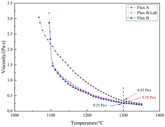
The key performance parameters of Flux B, prepared from industrial-grade raw materials via the spray-drying granulation system described in Section 2.4.1, are summarized in Table 10. The performance of Flux B is closely comparable to that of Flux B-Lab, and the small differences between the two are consistent with the typical variability associated with high-temperature mold-flux property measurements. As shown in Figure 10, both Flux B-Lab and Flux B exhibit lower viscosity and lower break temperatures than Flux A, which is beneficial for maintaining liquid slag fluidity and improving lubrication in the middle and lower parts of the mold. Moreover, the viscosity–temperature curve of Flux B is close to that of Flux B-Lab, indicating that the spray-drying granulation process effectively reproduced the rheological behavior of the laboratory-optimized formulation.
Table 10.
Key performance parameters of Flux B.
Figure 10.
Viscosity-temperature curves before and after mold flux optimization.
3.6. Industrial Trials
The industrial comparative trial was carried out using the twin-strand comparison method described in Section 2.4.2. Strand 1 employed Flux B, whereas Strand 2 continued to use Flux A as the reference. The casting speed, superheat, and secondary-cooling conditions were kept constant.
3.6.1. Liquid Slag Layer Thickness and Slag Consumption
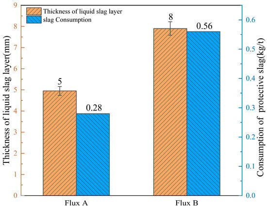
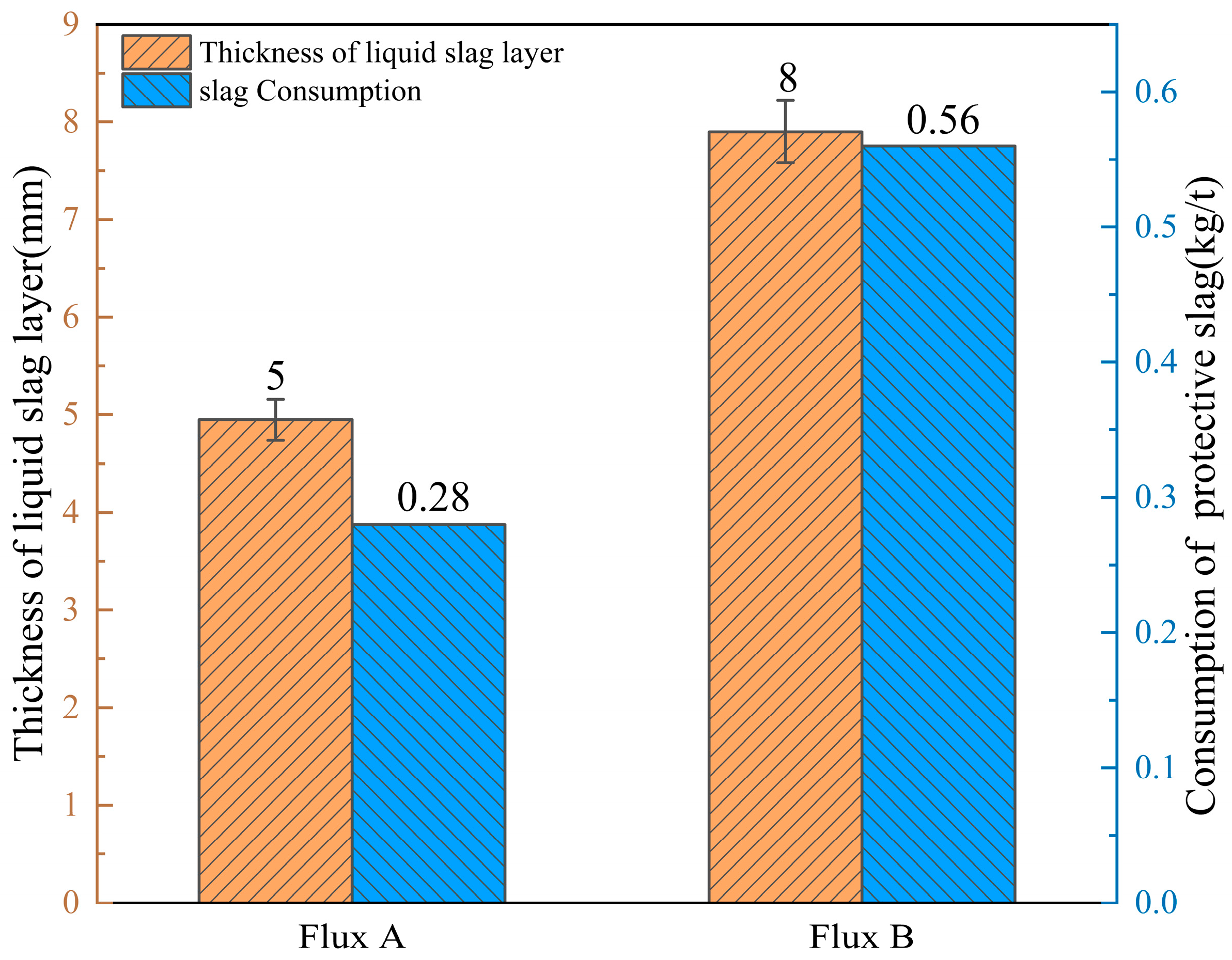
Figure 11 compares the liquid slag layer thickness and slag consumption of the two mold fluxes. Flux B maintained a stable liquid slag layer of approximately 8 mm, a marked improvement over Flux A (approximately 5 mm). Meanwhile, slag consumption increased from 0.28 kg/t with Flux A to 0.56 kg/t with Flux B, more than doubling the original value. The simultaneous increase in liquid slag layer thickness and slag consumption demonstrates that the optimized mold flux possesses superior liquid slag supply capacity and substantially improved lubrication performance.
Figure 11.
Comparison of liquid slag layer thickness and slag consumption. Error bars for liquid slag layer thickness indicate ±1 SD from four on-site measurements.
3.6.2. Bloom Surface Quality and Ultrasonic Testing Acceptance Rate
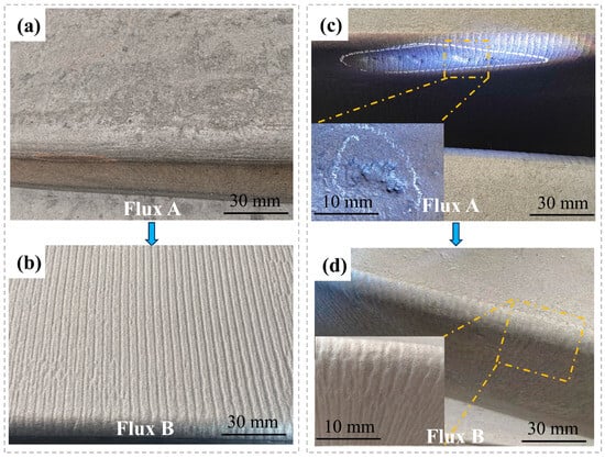
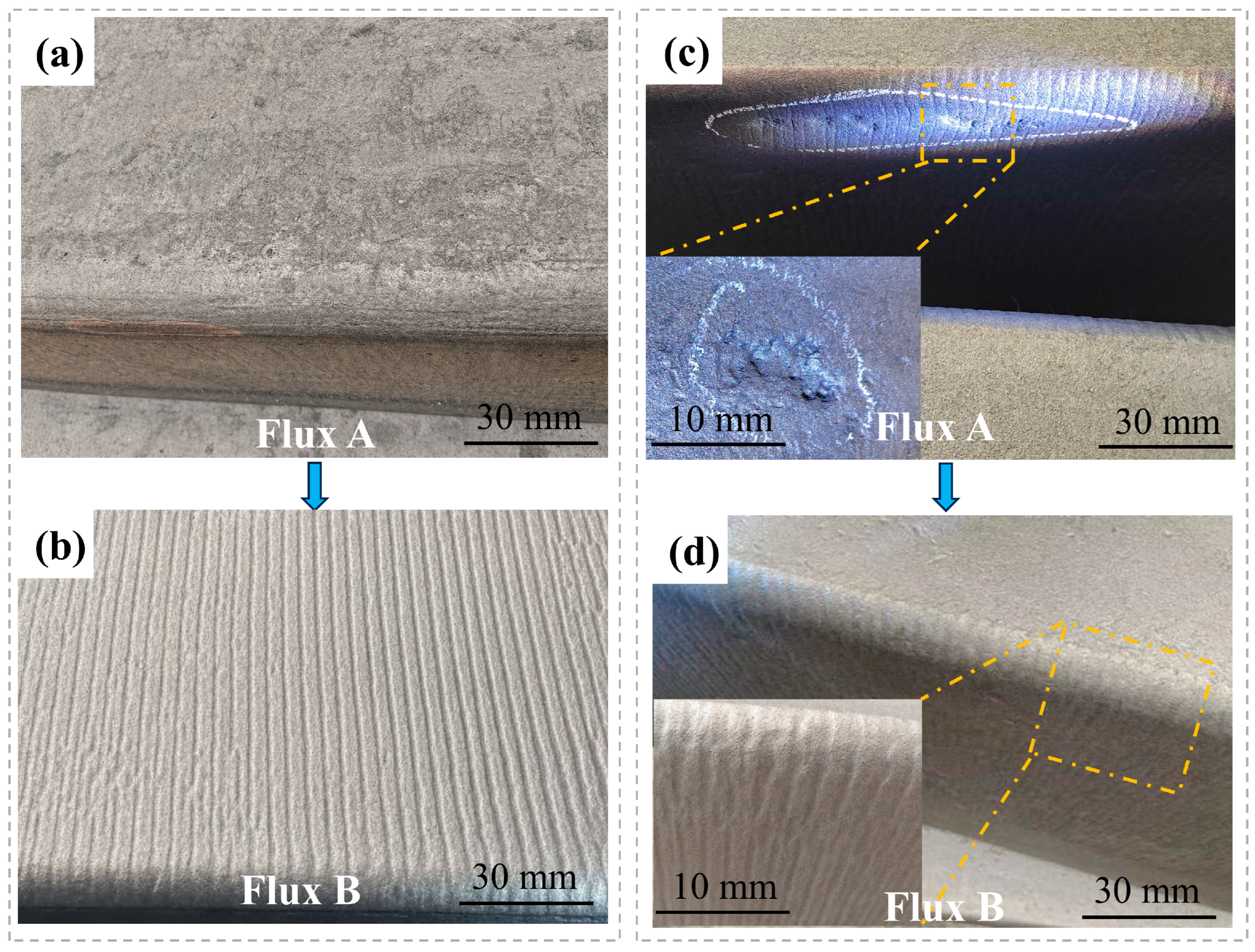
Figure 12 compares the surface quality of blooms cast with Flux A and Flux B. As shown in Figure 12a,b, the oscillation marks on blooms cast with Flux A are indistinct and irregular, whereas those on blooms cast with Flux B are clearly visible, uniform, and moderate in depth. Figure 12c,d show that blooms cast with Flux A exhibit numerous large slag pits at the corners. In contrast, blooms cast with Flux B show distinctly smoother corners, and although slag pits are not completely eliminated, their number, size, and depth are all substantially reduced. Overall, the use of Flux B leads to a marked decrease in surface depressions and cracks, indicating its superior lubrication and heat-transfer control capabilities, which promote uniform shell growth and significantly reduce the risk of surface crack formation.
Figure 12.
Effect of mold flux type on bloom surface quality: (a,b) comparison of oscillation mark morphology; (c,d) comparison of corner slag pits.
Surface defects on blooms are inherited by downstream rolled products, and their severity is ultimately reflected in the acceptance rate of the rolled products. In the industrial comparative trial, Flux B was applied over two consecutive heats, producing 40 blooms with a section size of 300 mm × 340 mm. The blooms were rolled into bars with diameters of 60–180 mm and subjected to ultrasonic testing. Compared with the rate before optimization, the acceptance rate increased from 88.5% to 98.6%. This result indicates that Flux B effectively controls bloom surface defects, achieves the intended optimization objectives, and meets the stringent production requirements for the high-quality continuous casting of sulfur-containing medium-carbon microalloyed steel blooms.
4. Conclusions
- (1)
- The relatively high contents of S, Mn, and Ti/N in the sulfur-containing medium-carbon microalloyed steel promote the precipitation of MnS and TiN–MnS complex inclusions along austenite grain boundaries, leading to grain-boundary embrittlement and reduced hot ductility. Meanwhile, the low thermal conductivity and high specific heat capacity of the steel intensify the temperature gradient between the bloom surface and interior, thereby exacerbating local thermal stress concentration in the solidifying shell. Together, these factors render the steel highly susceptible to cracking.
- (2)
- The originally used mold flux (Flux A) exhibits several performance deficiencies, including a high melting temperature, a long melting time, a high break temperature, and insufficient crystallization tendency. Consequently, it forms an excessively thin liquid slag layer (≤5 mm) within the mold, with poor coverage and even local discontinuity of the slag film. As a result, Flux A cannot provide continuous and stable liquid lubrication or homogenize heat transfer through a crystalline layer. This subjects the local shell to combined frictional and thermal stresses, ultimately promoting surface crack initiation.
- (3)
- To address these issues, an optimized mold flux design strategy was proposed to enhance crystallization performance while maintaining adequate lubrication, and Flux B was prepared using a spray-drying granulation system. In terms of composition, the basicity was increased from 0.95 to 1.1, the Al2O3 content from 9.48% to 11.16%, the F content from 4.93% to 5.58%, and the carbon content was reduced from 13.85% to 6.97%. In terms of performance, Flux B exhibited a lower melting temperature, a faster melting rate, and improved crystallization behavior, thereby achieving a balance between lubrication and heat transfer. Industrial trials demonstrated that Flux B effectively increased liquid slag layer thickness from approximately 5 mm to 8 mm and slag consumption from 0.28 kg/t to 0.56 kg/t, significantly suppressed bloom surface defects, and improved the ultrasonic testing acceptance rate of rolled products from 88.5% to 98.6%. These improvements confirm that Flux B meets the lubrication and heat-transfer requirements imposed by the steel’s solidification characteristics and the bloom casting process, demonstrating favorable industrial applicability and meeting the production requirements for the continuous casting of sulfur-containing medium-carbon microalloyed steel blooms. Overall, these results demonstrate that linking steel-specific solidification behavior with mold-flux property design provides a scientifically grounded and practically applicable route for improving bloom surface quality.
Author Contributions
Conceptualization, L.Z. and X.W.; Methodology, X.W. and Y.H.; Software, X.W.; Validation, X.W. and Y.H.; Formal Analysis, Y.H. and X.W.; Investigation, X.W.; Resources, L.Z. and Y.H.; Data Curation, X.W.; Writing—Original Draft Preparation, X.W.; Writing—Review and Editing, L.Z. and Y.H.; Visualization, X.W.; Supervision, L.Z.; Project Administration, L.Z.; Funding Acquisition, L.Z. All authors have read and agreed to the published version of the manuscript.
Funding
This research was funded by the Key Project of the National Natural Science Foundation of China—Joint Fund for Regional Innovation and Development: U21A20114; Hebei Province Innovation Capacity Enhancement Program: 24461002D; Hebei Provincial Science and Technology Programme of China: 23561007D; Key Project of the Natural Science Foundation of Hebei Province: E2022208019.
Data Availability Statement
The raw data supporting the conclusions of this article will be made available by the authors on request.
Acknowledgments
The authors acknowledge HBIS Company Limited and the Hebei High Quality Steel Continuous Casting Technology Innovation Center for their support of this study. Their generous sponsorship and technical assistance provided crucial resources for the experiments and significantly advanced the progress and outcomes of the research.
Conflicts of Interest
The authors declare no conflicts of interest.
References
- Xie, Y.; Meng, X.; Deng, X.; Li, S. Large (Ti, V) carbonitride in nonquenched and tempered steel 38MnVS6. Adv. Mater. Sci. Eng. 2022, 2022, 7281399. [Google Scholar] [CrossRef] [Scilit]
- Liu, Z.; Li, J.; Shen, W.; Fu, J. Industrial practice of tellurium-modified sulfides in non-quenched and tempered steel 38MnVS6. Iron Steel Vanadium Titan. 2023, 44, 200–204. [Google Scholar]
- Liu, Y.; Zhang, L.; Duan, H.; Zhang, Y.; Luo, Y.; Conejo, A.N. Extraction, Thermodynamic Analysis, and Precipitation Mechanism of MnS-TiN Complex Inclusions in Low-Sulfur Steels. Metall. Mater. Trans. A 2016, 47, 3015–3025. [Google Scholar] [CrossRef] [Scilit]
- Mintz, B.; Yue, S.; Jonas, J.J. Hot ductility of steels and its relationship to the problem of transverse cracking during continuous casting. Metall. Rev. 1991, 36, 187–220. [Google Scholar] [CrossRef] [Scilit]
- Ren, W.-Q.; Wang, L.; Xue, Z.-L.; Li, C.-Z.; Zhu, H.-Y.; Huang, A.; Li, C. A thermodynamic assessment of precipitation, growth, and control of MnS inclusion in U75V heavy rail steel. High Temp. Mater. Proc. 2021, 40, 178–192. [Google Scholar] [CrossRef] [Scilit]
- Meng, X.; Gao, X.; Huang, S.; Zhu, M. Cross-Scale Modeling of MnS Precipitation for Steel Solidification. Metals 2018, 8, 529. [Google Scholar] [CrossRef] [Scilit]
- Zhang, H.; Feng, G.; Liu, X.; Wang, B.; Liu, X. Effect of sulfur content on the composition of inclusions and MnS precipitation behavior in bearing steel. Metals 2020, 10, 570. [Google Scholar] [CrossRef] [Scilit]
- Tanaka, Y.; Pahlevani, F.; Moon, S.-C.; Dippenaar, R.; Sahajwalla, V. In situ characterisation of MnS precipitation in high carbon steel. Sci. Rep. 2019, 9, 10096. [Google Scholar] [CrossRef] [Scilit]
- Kim, K.H.; Yeo, T.J.; Oh, K.H.; Lee, D.N. Effect of Carbon and Sulfur in Continuously Cast Strand on Longitudinal Surface Cracks. ISIJ Int. 1996, 36, 284–289. [Google Scholar] [CrossRef] [Scilit]
- Zaitsev, A.; Arutyunyan, N.; Koldaev, A. Hot Ductility, Homogeneity of the Composition, Structure, and Properties of High-Strength Microalloyed Steels: A Critical Review. Metals 2023, 13, 1066. [Google Scholar] [CrossRef] [Scilit]
- Krobath, R.; Bernhard, C. Experimental Quantification of Critical Parameters for Prediction of Surface Crack Formation in Continuous Casting. Steel Res. Int. 2020, 91, 2000234. [Google Scholar] [CrossRef] [Scilit]
- Liu, P.; Cai, Z.; Zhu, M. Effects of sulphur content and cooling rate on the precipitation characteristics of MnS in high-sulphur peritectic steel. Ironmak. Steelmak. 2024, 51, 251–264. [Google Scholar] [CrossRef] [Scilit]
- Xing, L.; Fan, X.; Wang, M.; Zhao, L.; Bao, Y. The Formation Mechanism of Proeutectoid Ferrite on Medium-Carbon Sulfur-Containing Bloom. Metall. Mater. Trans. B 2021, 52, 3208–3219. [Google Scholar] [CrossRef] [Scilit]
- Li, M. Studies on the Control of Internal Quality and Surface Crack of Non-Quenched and Tempered Steel for Automobile Crankshaft. Ph.D. Thesis, University of Science and Technology Beijing, Beijing, China, 2024. [Google Scholar]
- Xing, L.; Zhang, Z.; Bao, Y. Hot ductility behavior of medium carbon sulfur-containing alloy steel. J. Mater. Res. Technol. 2022, 19, 1367–1378. [Google Scholar] [CrossRef] [Scilit]
- Cowley, A.; Mintz, B. Relative importance of transformation temperatures and sulphur content on hot ductility of steels. Mater. Sci. Technol. 2004, 20, 1431–1439. [Google Scholar] [CrossRef] [Scilit]
- de Toledo, G.A.; Campo, O.; Lainez, E. Influence of sulfur and Mn/S ratio on the hot ductility of steels during continuous casting. Steel Res. 1993, 64, 292–299. [Google Scholar] [CrossRef] [Scilit]
- Xing, L.; Zhang, Z.; Zhao, L.; Bao, Y. Effects of Sulfur on the Surface Crack in Medium Carbon Bloom. Steel Res. Int. 2022, 93, 3208–3219. [Google Scholar] [CrossRef] [Scilit]
- Xing, L.D. Study on Formation Mechanism and Control of Surface Micro-Cracks in Sulfur-Containing Bloom. Ph.D. Thesis, University of Science and Technology Beijing, Beijing, China, 2022. [Google Scholar]
- Xia, Y.L.; Wang, L.; Tie, Z.P.; Lan, P.; Tang, H.Y.; Zhang, J.Q. As-cast microstructure of continuously cast bloom of high-carbon microalloyed steel for fracture-split connecting rods. Chin. J. Eng. 2022, 44, 189–197. [Google Scholar] [CrossRef]
- Xiao, C.; Zhang, J.M.; Luo, Y.Z.; Hu, Z.F. Solidification behavior during bloom continuous casting. J. Univ. Sci. Technol. Beijing 2012, 34, 1011–1016. [Google Scholar] [CrossRef]
- Chaudhary, R.; Ji, C.; Thomas, B.G.; Vanka, S.P. Transient Turbulent Flow in a Liquid-Metal Model of Continuous Casting, Including Comparison of Six Different Methods. Metall. Mater. Trans. B 2011, 42, 987–1007. [Google Scholar] [CrossRef] [Scilit]
- Zhu, L.L.; He, S.P.; Mao, J.H. Series planning of mold fluxes for continuous casting of extra-thick slabs. Iron Steel 2016, 51, 44–48. [Google Scholar] [CrossRef]
- Zhang, L.; Thomas, B.G. State of the Art in Evaluation and Control of Steel Cleanliness. ISIJ Int. 2003, 43, 271–291. [Google Scholar] [CrossRef] [Scilit]
- He, Y.M.; Wang, Q.; Hu, B.; Zhu, L.L.; Chen, W.M.; He, S.P. Application of high-basicity mould fluxes for continuous casting of large steel slabs. Ironmak. Steelmak. 2016, 43, 588–593. [Google Scholar] [CrossRef] [Scilit]
- Hanao, M. Influence of Basicity of Mold Flux on its Crystallization Rate. ISIJ Int. 2013, 53, 648–654. [Google Scholar] [CrossRef] [Scilit]
- Mills, K.C. Structure and properties of slags used in the continuous casting of steel: Part 2 specialist mould powders. ISIJ Int. 2016, 56, 14–23. [Google Scholar] [CrossRef] [Scilit]
- Wang, Z.; Sohn, I. Review on the high-temperature thermophysical properties of continuous casting mold fluxes for highly alloyed steels. ISIJ Int. 2020, 60, 2705–2716. [Google Scholar] [CrossRef] [Scilit]
- Sarkar, R.; Li, Z. Isothermal and non-isothermal crystallization kinetics of mold fluxes used in continuous casting of steel: A review. Metall. Mater. Trans. B 2021, 52, 1357–1378. [Google Scholar] [CrossRef] [Scilit]
- Wang, W.L.; Cai, Z.Z.; Zhu, M.Y. Heat flux and thermal behavior of wide-thick slab continuous casting molds for peritectic steel. Chin. J. Eng. 2013, 35, 510–516. [Google Scholar] [CrossRef]
- Stulov, V.V. Cooling a slab continuous-casting mold. J. Mach. Manuf. Reliab. 2012, 41, 163–167. [Google Scholar] [CrossRef] [Scilit]
- Gruber, N. Effect of carbon on the melting behavior of a mold powder under high heating rates. BHM Berg Hüttenmänn. Monatshefte 2023, 168, 521–526. [Google Scholar] [CrossRef] [Scilit]
- Mills, K.C.; Fox, A.B. The Role of Mould Fluxes in Continuous Casting-So Simple Yet So Complex. ISIJ Int. 2003, 43, 1479–1486. [Google Scholar] [CrossRef] [Scilit]
- Wang, X.; Jin, H.; Zhu, L.; Xu, Y.; Liu, R.; Piao, Z.; Qu, S. Effect of CaF2 on the viscosity and microstructure of CaO–SiO2–Al2O3 based continuous casting mold flux. Metals 2019, 9, 871. [Google Scholar] [CrossRef] [Scilit]
- Yuan, Z.; Zhu, L.; Wang, X.; Zhang, K. Analysis of longitudinal cracking and mold flux optimization in high-speed continuous casting of hyper-peritectic steel thin slabs. Metals 2024, 14, 909. [Google Scholar] [CrossRef] [Scilit]
- Ding, Z.; Wang, C.; Wang, X.; Xiao, P.; Zhu, L.; Wang, S. The Influence of Process and Slag Parameters on the Liquid Slag Layer in Continuous Casting Mold for Large Billets. Crystals 2025, 15, 388. [Google Scholar] [CrossRef] [Scilit]
- Sun, R.Z.; Li, T.T. Causes and evolution of network cracks on the surface of steel plates. Hebei Metall. 2023, 52, 30–35. [Google Scholar] [CrossRef]
- Liu, J.; Wen, G.; Li, Y.; Tang, P. A Model Estimating the Slab Corner Transverse Cracking Susceptibility of Microalloyed Steel Based on Microstructure. Mater. Trans. 2015, 57, 20–24. [Google Scholar] [CrossRef] [Scilit]
- Cheng, P.; Wang, G.H.; Li, Q.P.; Chen, Y.Q.; Li, C.B.; Liu, Y. Effect of mold liquid slag layer thickness on the surface quality of large blooms. Steelmaking 2025, 41, 85–91. [Google Scholar]
- Wu, H.; Li, X.; Wang, Z.; Liu, W. Effect of TiN on Sulfide Morphology of Non-Quenched and Tempered Steel. Metals 2022, 12, 1402. [Google Scholar] [CrossRef] [Scilit]
- Chen, W.; Yang, G.; Zhu, L.; Wang, X.; He, B. Reducing Surface Cracks and Improving Cleanliness of H-Beam Blanks in Continuous Casting—Improving continuous casting of H-beam blanks. High Temp. Mater. Proc. 2019, 38, 612–620. [Google Scholar] [CrossRef] [Scilit]
- Xu, J.F.; He, S.P.; Jiang, X.P.; Wu, T.; Wang, Q. Formation of Surface Depression during Continuous Casting of High-Al TRIP Steel. Metals 2019, 9, 204. [Google Scholar] [CrossRef] [Scilit]
- Xu, J.F.; He, S.P.; Jiang, X.; Wu, T.; Wang, Q. Analysis of Crack Susceptibility of Regular Carbon Steel Slabs Using Volume Based Shrinkage Index. ISIJ Int. 2013, 53, 1812–1817. [Google Scholar] [CrossRef] [Scilit]
- Feng, Y.; Zalonik, M.; Thomas, B.G.; Phillion, A.B. Meso-scale simulation of liquid feeding in an equiaxed dendritic mushy zone. Materialia 2020, 9, 100612. [Google Scholar] [CrossRef] [Scilit]
- Takada, H.; Bessho, I.; Ito, T. Effect of sulfur content and solidification variables on morphology and distribution of sulfide in steel ingots. Tetsu-to-Hagané 1976, 62, 1319–1328. [Google Scholar] [CrossRef] [Scilit]
- Fan, Y.; Kameda, K.; Hu, X.; Matsuura, H. Precipitation Behavior of MnS Inclusion in Unidirectionally-Solidified Fe-18Mn-1Al-0.3C Steels. ISIJ Int. 2024, 64, 920–927. [Google Scholar] [CrossRef] [Scilit]
- Mintz, B.; Qaban, A.; Kang, S.E. The Influence of Small Additions of Alloying Elements on the Hot Ductility of AHSS Steels: A Critical Review Part 2. Metals 2023, 13, 406. [Google Scholar] [CrossRef] [Scilit]
- Li, Y.; Xing, W.; Li, X.; Chen, B.; Ma, Y.; Liu, K.; Min, Y. Effect of Mg Addition on the Microstructure and Properties of a Heat-Affected Zone in Submerged Arc Welding of an Al-Killed Low Carbon Steel. Materials 2021, 14, 2445. [Google Scholar] [CrossRef] [Scilit]
- Song, F.; Yin, C.; Hu, F.; Wu, K. Effects of Mn-depleted zone formation on acicular ferrite transformation in weld metals under high heat input welding. Materials 2022, 15, 8477. [Google Scholar] [CrossRef] [Scilit]
- Zhou, X.; Shao, Z.; Tian, F.; Hopper, C.; Jiang, J. Microstructural effects on central crack formation in hot cross-wedge-rolled high-strength steel parts. J. Mater. Sci. 2020, 55, 9608–9622. [Google Scholar] [CrossRef] [Scilit]
- Duwuri, P.; Petrus, B.; Thomas, B.G. Correlation for Mold Heat Flux Measured in a Thin-Slab Casting Mold. In Proceedings of the AISTech-Iron and Steel Technology Conference, Indianapolis, IN, USA, 5–8 May 2014; pp. 2881–2893. [Google Scholar]
- Meng, Y.; Thomas, B.G. Heat-transfer and solidification model of continuous slab casting: CON1D. Metall. Mater. Trans. B 2003, 34, 685–705. [Google Scholar] [CrossRef] [Scilit]
- Li, J.Q.; Wang, G.R.; Dai, Y.Z. Study on reducing longitudinal surface cracks of carbon–manganese steel blooms during large-section bloom continuous casting. Contin. Cast. 2016, 41, 41–46. [Google Scholar] [CrossRef]
- Meng, Y.; Thomas, B.G. Interfacial friction related phenomena in continuous casting with mold slags. In Proceedings of the ISSTECH-Conference Proceedings, Indianapolis, IN, USA, 27–30 April 2003; pp. 589–608. [Google Scholar]
- Stone, D.T.; Thomas, B.G. Measurement and Modeling of Heat Transfer Across Interfacial Mold Flux Layers. Can. Metall. Q. 1999, 38, 363–375. [Google Scholar] [CrossRef]
- Nakada, H.; Susa, M.; Seko, Y.; Hayashi, M.; Nagata, K. Mechanism of Heat Transfer Reduction by Crystallization of Mold Flux for Continuous Casting. ISIJ Int. 2008, 48, 446–453. [Google Scholar] [CrossRef] [Scilit]
- Susa, M.; Kushimoto, A.; Toyota, H.; Hayashi, M.; Endo, R.; Kobayashi, Y. Effects of both crystallisation and iron oxides on the radiative heat transfer in mould fluxes. ISIJ Int. 2009, 49, 1722–1729. [Google Scholar] [CrossRef] [Scilit]
- Gu, K.; Wang, W.; Wei, J.; Matsuura, H.; Tsukihashi, F.; Sohn, I.; Min, D.J. Heat-transfer phenomena across mold flux by using the inferred emitter technique. Metall. Mater. Trans. B 2012, 43, 1393–1404. [Google Scholar] [CrossRef] [Scilit]
- Zhou, L.; Wang, W.; Ma, F.; Li, J.; Wei, J.; Matsuura, H.; Tsukihashi, F. A Kinetic Study of the Effect of Basicity on the Mold Fluxes Crystallization. Metall. Mater. Trans. B 2012, 43, 354–362. [Google Scholar] [CrossRef] [Scilit]

Disclaimer/Publisher’s Note: The statements, opinions and data contained in all publications are solely those of the individual author(s) and contributor(s) and not of MDPI and/or the editor(s). MDPI and/or the editor(s) disclaim responsibility for any injury to people or property resulting from any ideas, methods, instructions or products referred to in the content. |
© 2026 by the authors. Licensee MDPI, Basel, Switzerland. This article is an open access article distributed under the terms and conditions of the Creative Commons Attribution (CC BY) license.