


Abstract
We designed a specialized structure for friction stir-welded hollow extrusions for high-speed trains in order to fulfill security and economic requirements. A sequentially coupled thermo-mechanical model was used to investigate the thermal stress distribution in the designed structure. The results show that stress concentration was the most important factor in high calculated stress and that increasing the supporting rib width and the arc radius on the advancing side of the supporting rib can effectively improve structural security. Finally, an optimized structure was obtained, and friction stir welding experiments were carried out to verify the simulation’s precision.
1. Introduction
Aluminum hollow extrusions have been extensively used in the railway car-body manufacturing industry for two reasons: First, the use of an aluminum alloy will reduce the vehicle’s weight, meaning that fuel consumption, which accounts for more than 99% of a vehicle’s life cycle energy, can be reduced significantly [1,2]. Furthermore, 6000 series aluminum alloys are used most extensively on account of their high strength/weight ratio, good ductility and formability, and strong corrosion resistance [3,4]. Second, the hollow extrusions can integrate the functions of the beams and plates because of their high rigidity, thus decreasing the number of components to be welded and shortening the welding line considerably [1,5].
Friction stir welding (FSW), as a solid-state joining technique, can eliminate the typical defects caused by conventional fusion welding and is a promising method in welding hollow extrusions [6,7]. The technological characteristics of FSW mean that the welding force plays a key role in the welding process. Trimble et al. [8] recorded the forces in a three-axis coordinate system when friction stir-welding AA 2024-T3 plates. The results showed that the vertical force Fz was much larger than the other two in-plane forces (Fx and Fy), and it would reach a peak value of 21 kN when the tool (with a pin length of 4.6 mm) reached the target depth of 4.8 mm. Astarita et al. [9] studied the influence of process parameters on the welding forces in friction stir-welded AA 2024-T3 sheets, and a maximal vertical force from 15 to 18 kN was required to achieve a defect-free weld. These investigations demonstrate that a considerably large welding force is needed to achieve a good weld. When the welding force is not large enough, it is easy for welding defects to form. Elangovan et al. [10] conducted friction stir welding on a 6 mm thick AA6061 aluminum alloy using a tool with a pin length of 5.5 mm and investigated the effect of axial force on weld formation and mechanical properties. They found that when the axial force was 6 kN, root flaws and even surface grooves occurred. When the axial forces were 7 kN and 8 kN, defect-free welds were achieved, and the welds produced with an axial force of 7 kN exhibited superior tensile properties. However, when FSW is applied to welding aluminum hollow extrusions, some practical difficulties will be encountered. This is because a sufficiently high welding force is needed to achieve a good weld with FSW, but the hollow extrusions have a lower bearing capacity due to a lack of supporting backing plates. So, developing a structural design for hollow extrusions to meet security requirements represents a key challenge.
Until now, the structural design of hollow extrusions has mainly been achieved through the empirical approach or the traditional trial-and-error method. In practical circumstances, some hollow extrusions with various cross-section shapes need to be machined, and the extrusion dies must be repaired or even remanufactured. Moreover, many welding tests are required to examine the security of the hollow extrusions. This is very time-consuming and extremely expensive; therefore, a solution is needed that will allow us to evaluate the structural safety in a short time at low cost. A few authors have attempted to solve this problem using numerical simulation methods. Kawasaki et al. [11] introduced a design for a joint for FSW-ed aluminum hollow extrusions according to material selection and welding conditions and built a numerical model using LS-DYNA to study the thermal stress distribution in the structures. The simulated data agreed well with the measured ones, all showing that the overall structure, including the joint, could sustain the welding load in the process and be safe enough for real-world application. Shahri et al. [12,13] tested the fatigue properties of hollow extrusions (no information was given about the structural design) welded via FSW and carried out a stress analysis on the profiles using the critical distance method. The authors found that the failures occurred at either interface notches in the weld or at stress concentrations in the base material, and their method was not able to predict the failure location and fatigue limit.
In summary, numerical simulations have been utilized to investigate the security of design profiles and guide structural designs. But previous investigations have only demonstrated the safety of current structures, and detailed methods for designing hollow extrusion structures have not yet been reported. Therefore, in this paper, we report on the design of specialized hollow extrusions for HSTs manufactured via friction stir welding according to security and economic concerns, establish a thermal–mechanical model to assess the security of structures with various cross-section shapes, and propose and friction stir-weld an optimized structure to verify the reliability of the structural design.
2. Experimental Procedures
2.1. Material Selection and Production of the Hollow Extrusions
The AA6005A aluminum alloy was extruded and then subjected to T6 heat treatment (solution + artificial aging) prior to welding. The nominal chemical compositions are listed in terms of weight percent and mechanical properties in Table 1.
Table 1.
Chemical compositions and mechanical properties of 6005A-T6 aluminum profile.
In the actual manufacturing process, a 6005A aluminum alloy ingot was first produced using the hot-top continuous casting method and then machined via a computer numerical control (CNC) (Heilongjiang Guangda CNC Machine Tool Co., Ltd., Harbin, China) lathe to remove surface impurities, including the loose layer, segregation layer, oil pollution, and oxide. Then, an induction heating furnace was used to heat the ingot. The allowable temperature range was 460–520 °C, which ensured that the ingot had a sufficient plastic flow capacity, averting some surface defects such as overburning and hot cracking [14]. This was followed by the most important stage, hot extrusion: the ingot was placed into the porthole extrusion die system, consisting of the upper die and lower die, and the extrusion process was performed at a constant isothermal temperature of 460–500 °C and an exit speed of 1.2–1.8 m/min. After this, press quenching in an aqueous medium, a method of combining solution treatment and extrusion, was performed to avoid the precipitation of Mg2Si and maintain the Mg and Si in the supersaturated solid solution. This technology can not only achieve the desired microstructure but also satisfy the requirement of modern industry for short production cycles and low costs. Finally, the hollow extrusions were subjected to artificial aging at 175 °C for 8 h for the purpose of improving their strength quickly.
2.2. Welding Experiments
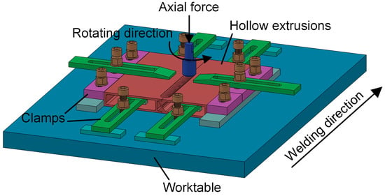
To investigate the structural safety of the hollow extrusions, we conducted friction stir welding experiments. The 6005A hollow extrusions were machined into welding samples with a length of 300 mm, a total width of approximately 250 mm, and a butt thickness of 4.7 mm. After mechanical abrading with steel brush and chemical cleaning with acetone, the samples were clamped onto the welding worktable; a backing plate was not needed. The welds were fabricated using an FSW machine (FSW-3LM-003, Beijing FSW Technology Co., Ltd, Beijing, China) along the longitudinal direction, which was parallel to the extrusion direction. The welding tool consisted of a 24 mm diameter shoulder and a conical right-hand screwed pin; the median diameter and length of the pin were 8.5 mm and 4.5 mm, respectively. Figure 1 shows the schematic view of the laboratory fixtures for producing an FSW joint. The specific FSW parameters are as follows: rotational speed of 1000 r/min, welding speed of 1000 mm/min, axial force of 17 kN, and tilt angle of 1.5°. The welding experiments were repeated three times to ensure reliable results. Specimen preparation and metallographic analysis were carried out according to the ASTM E3 [15] and ASTM E407 [16] standards, respectively.
Figure 1.
Schematic drawing of the fixtures for fabricating an FSW joint.
3. Structural Design of the Hollow Extrusions
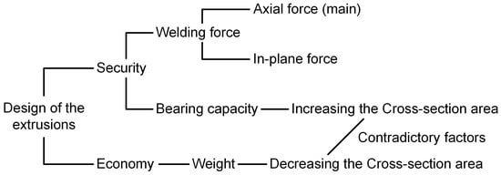
When it comes to the structural design of hollow extrusions, two main factors must be taken into consideration, security and economy, as shown in Figure 2.
Figure 2.
Important factors to be considered in the structural design of extrusions.
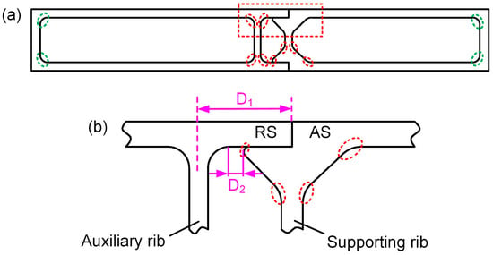
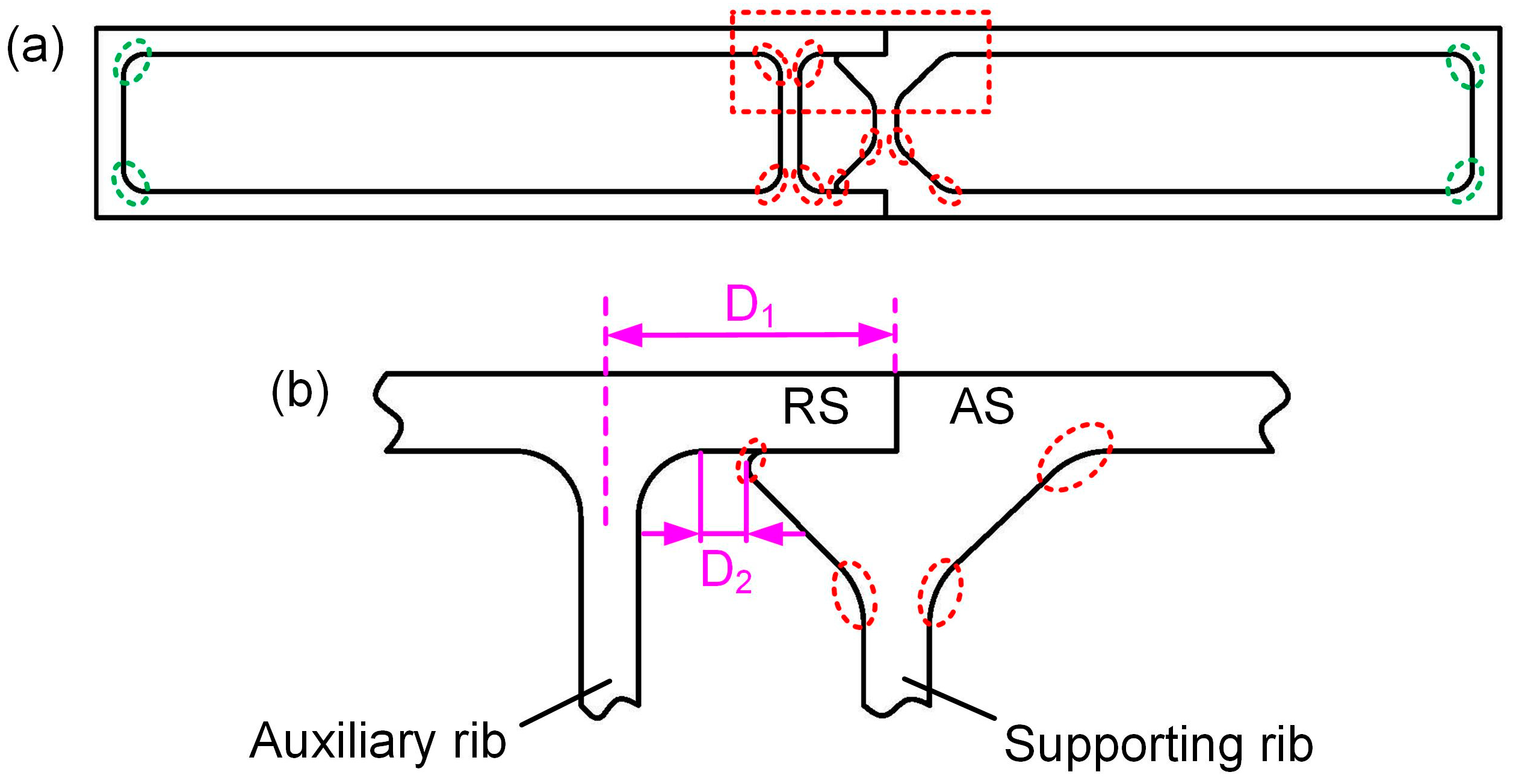
The first step is to assess the structural security from the angle of welding force and the bearing capacity of the hollow extrusions. Figure 3 shows the cross-section and local details of our hollow extrusions, determined based on several factors. Firstly, heat is generated by friction between the tool and matrix, as well as through plastic deformation, and the heat input in the FSW is much lower than that in conventional fusion methods. The maximum temperature ranges from 0.8 to 0.9 Tm (where Tm is the melting temperature of the material), which means that there is no melting during the FSW, and filler metal material is not needed. In addition, the introduction of a gap at the butting interface may lead to a reduction in the effective bearing area, which has a negative impact on the mechanical properties of the joint [17,18]. Therefore, the joint is designed as an I-shape that has no gaps when we ignore machining accuracy. Secondly, when a non-consumable rotating tool is inserted into the workpiece and rigidly fixed using clamps, welding forces, including vertical and in-plane forces, will be generated through deformed material, blocking the rotation and advancement of the tool, and the vertical force is the predominant force in achieving a defect-free weld. We must be mindful that the vertical force is not distributed uniformly on the shoulder. It is well known that the temperature distribution in the weld zone is asymmetric due to the difference in the flow velocity of the plastic material on the retreating side (RS) and advancing side (AS), and it has been proven via numerical simulations and experimental results that the temperature in the region on the RS is lower than the corresponding region on the AS [19]. Thus, the material on the RS will bear a larger vertical force Fz because the yield strength will increase monotonously with the decrease in temperature. Based on these considerations, the supporting rib is placed directly under the joint line, bearing most of the axial force, and an auxiliary rib is added on the RS to share part of the axial force. The distance of the auxiliary rib from the welding center D1 determines the extent to which it undertakes the welding force, and the function of the auxiliary rib is inversely proportional to D1. The value of D1 depends directly on the distance D2, shown in Figure 3b, and D2 cannot be very close to zero in terms of workpiece assembly. Thirdly, several filets marked by red and green ellipses are added to the corners; they can improve the “liquidity” of plasticized materials at the corners and prevent some defects in the extrusion process. Additionally, the filets located at the supporting and auxiliary rib (marked by red ellipses) allow a smooth transition and significantly reduce the degree of stress concentration. Fourthly, other non-critical measurements of the hollow extrusion, including the length, width, height, and wall thickness, can be obtained according to previous design experience.
Figure 3.
Cross-section shape of (a) the hollow extrusions and (b) local details taken from the red dotted box in (a).
The second step is to consider the economic aspects of manufacturing the hollow extrusions; the requirement is to reduce the weight as much as possible, i.e., to minimize the cross-sectional areas. Meanwhile, maximizing the cross-sectional areas within the acceptable range represents the best solution to ensure structural safety. Hence, a compromise needs to be put forward. In this work, initial structures are designed for hollow extrusions and a numerical simulation method is used to evaluate their structural safety. Through analysis of the simulated results, the “dangerous” locations can be found and modifications can be made by changing the dimensions of the corresponding locations. Finally, an optimized structure is proposed to simultaneously meet the safety criteria and economic requirements, allowing the local cross-sectional area of the extrusion to be reduced by approximately 5%.
4. Model Description
In order to maintain sufficient precision and remarkably improve computing efficiency, a sequentially coupled thermo-mechanical method including a transient heat transfer model and a static general model is used to investigate the thermal stress distribution in the hollow extrusions. That is, the thermal model is solved first (with a given moving heat source to calculate the temperature field), and then the temperature field is applied as a load to the mechanical model. In the mechanical model, material properties (yield strength, elastic modulus, etc.) are updated with the temperature, but the mechanical model does not affect the thermal model in return.
4.1. Meshing and Material Properties
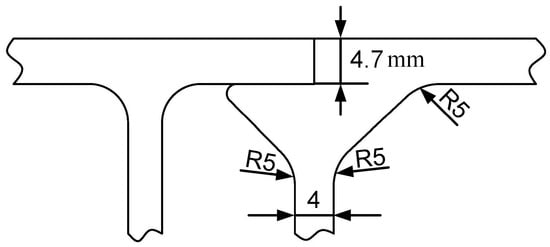
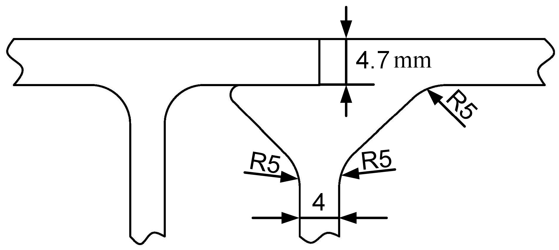
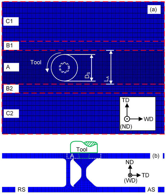
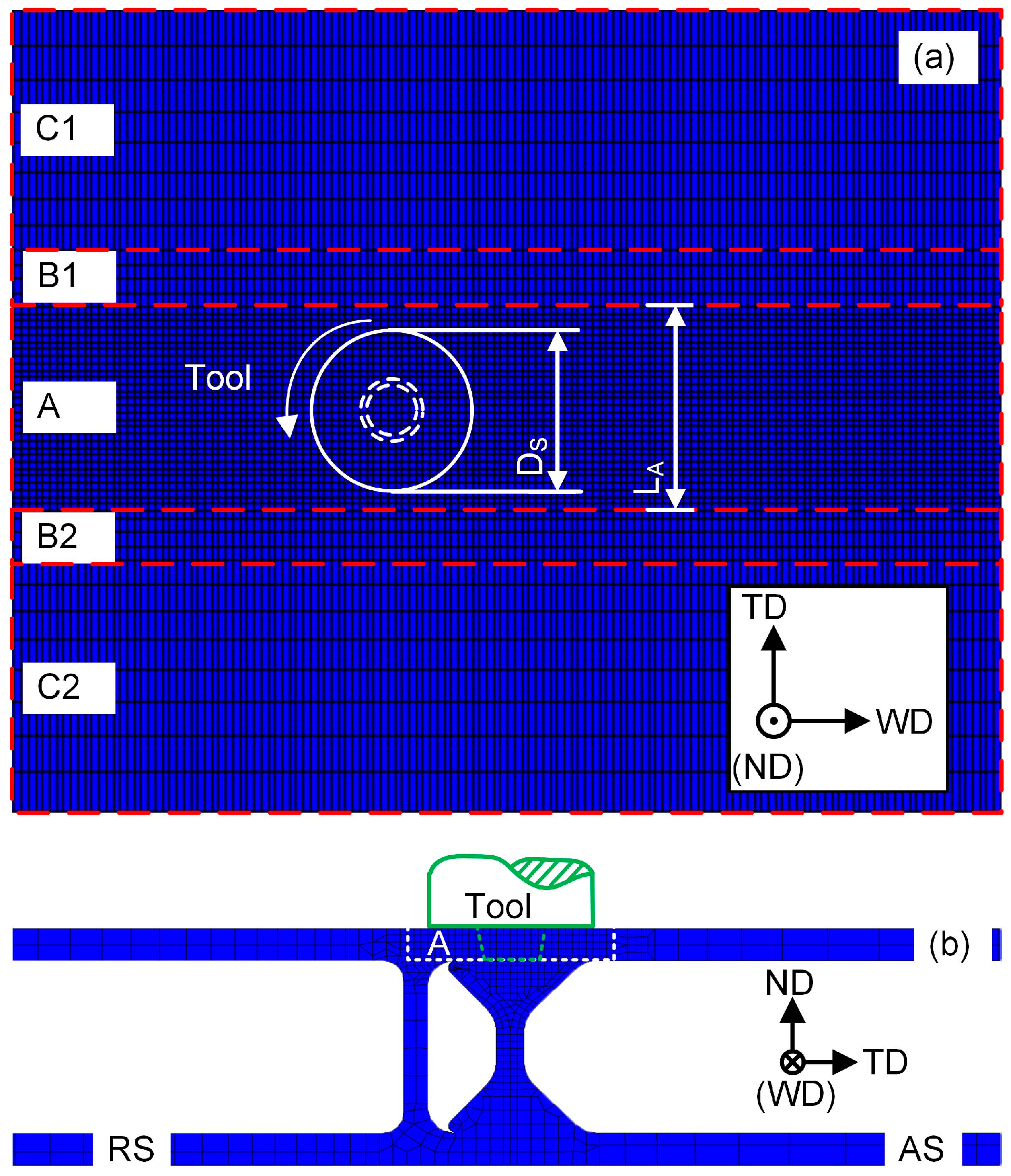
The dimensions of the initial structures for the hollow extrusions are shown in Figure 4. Two profiles must be meshed due to their structural asymmetry, and the detailed mesh generation is shown in Figure 5. The meshes with a dimension of 1 mm × 1 mm × 1 mm in the A zone are smaller than those in the B and C zone, and the length of the A zone LA is greater than the shoulder diameter DS, which can guarantee computational accuracy in thermal and stress fields in the weld zone. The meshes in the zones B (B1 and B2) and C (C1 and C2) will become coarser. In other words, the dimensions of the meshes change along the transverse direction (TD) and normal direction (ND), but not along the welding direction (WD). The finite element thermal model consists of 166, 428 nodes and 130, 400 elements.
Figure 4.
The dimensions of the initial structures designed for hollow extrusions (Unit: mm).
Figure 5.
Grid mesh of the established thermal model: (a) top view, (b) left view.
The values of different temperature-dependent physical parameters at elevated temperatures are listed in Table 2, and the values that cannot be obtained directly are deduced from the fitting curves. The density and Poisson ratio of the material vary slightly with temperature, and they can be taken as 2700 kg/m3 and 0.3, respectively.
Table 2.
Temperature-dependent physical properties of 6005A-T6 alloy. Adapted from ref. [20].
4.2. Thermal Model
In the thermal model, the face flux qshoulder is used to describe the surface heat from friction between the shoulder and workpiece, and the body flux qpin is used to describe the inner heat from plastic deformation and friction between the pin and workpiece. The specific formulae can be written as follows [21,22]:
where ω is the rotation speed, r is the distance from the integration point to the tool center, is the yield strength, which is updated according to the instantaneous temperature provided by the thermal model, R1 is the radius of the shoulder, R2 and R3 are the root and tip radius of the pin, respectively, and α is the semi-cone angle of the pin.
4.3. Mechanical Model
Then, the thermal histories predicted by the previous thermal model are applied to the mechanical model as the boundary condition. The backing plate and clamps are treated as rigid constraints. The force is caused by the thermal expansion of the extrusions, plus the downward force exerted by the tool. For the medium with a volume of V and surface boundary of S, the energy conservation equation can be expressed as
where ρ is the density, is the inner energy, U is the volume heat flux, σij is the Cauchy stress, νi is the velocity field, and H is the density of heat flux per unit area. According to the virtual work theory, the structural displacement ui satisfies the following formula:
where bi is the volume force.
In the MSC.MARC finite element analysis, the material is modeled as elastic–plastic with isotropic properties. The von Mises yield criterion is adopted, with isotropic hardening and strain rate sensitivity treated using a piecewise linear method. Material properties (Young’s modulus, yield strength, thermal expansion coefficient, etc.) are defined via tabular input as functions of the temperature. Under this setting, the yield stress is not a function of the temperature alone; it also depends on the equivalent plastic strain (hardening) and, through piecewise linear interpolation, on the equivalent plastic strain rate (rate sensitivity). The yield function is therefore written as
where Sij is the stress deviation, is the von Mises equivalent stress, and is the current yield strength, which is interpolated from user-defined tables as a function of the equivalent plastic strain , temperature T, and equivalent plastic strain rate . The hardening law is isotropic, meaning that the yield surface expands uniformly with increasing p.
The subsequent plastic deformation needs dF = 0; then, the Formula (5) can be presented as
The total thermo-elastic–plastic incremental strain in the model consists of elastic, plastic and thermal strain, and the total incremental strain can be expressed as
Further, the change rate of the elastic stress can be given as
where is the elastic stiffness matrix for a linear isotropic material that depends on the temperature and reflects the elastic constitutive relationship of the material.
5. Results and Discussion
It is well known that the tool suffers forces via a three-coordinate axis due to its rotational and linear movement, including the vertical axial force Fz in the ND, the longitudinal force Fx in the WD, and the transverse force Fy in the TD. The value of Fz is much higher than Fx and Fy, and it will reach its peak when the tool finishes plunging and is about to traverse along the joint line [23,24]. At the same moment, the temperature of the points directly under the tool will reach the highest temperature, which indicates the lowest bearing capacity in the hollow extrusions [25]. So, the moment the tool has finished plunging and is preparing to travel along the WD can be seen as the most “dangerous” moment.
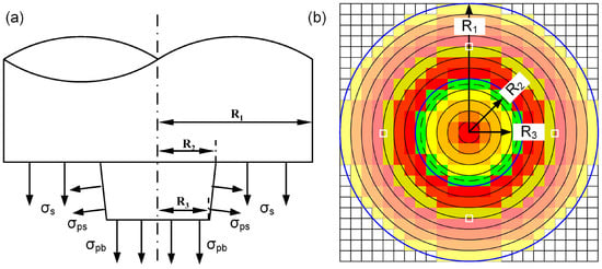
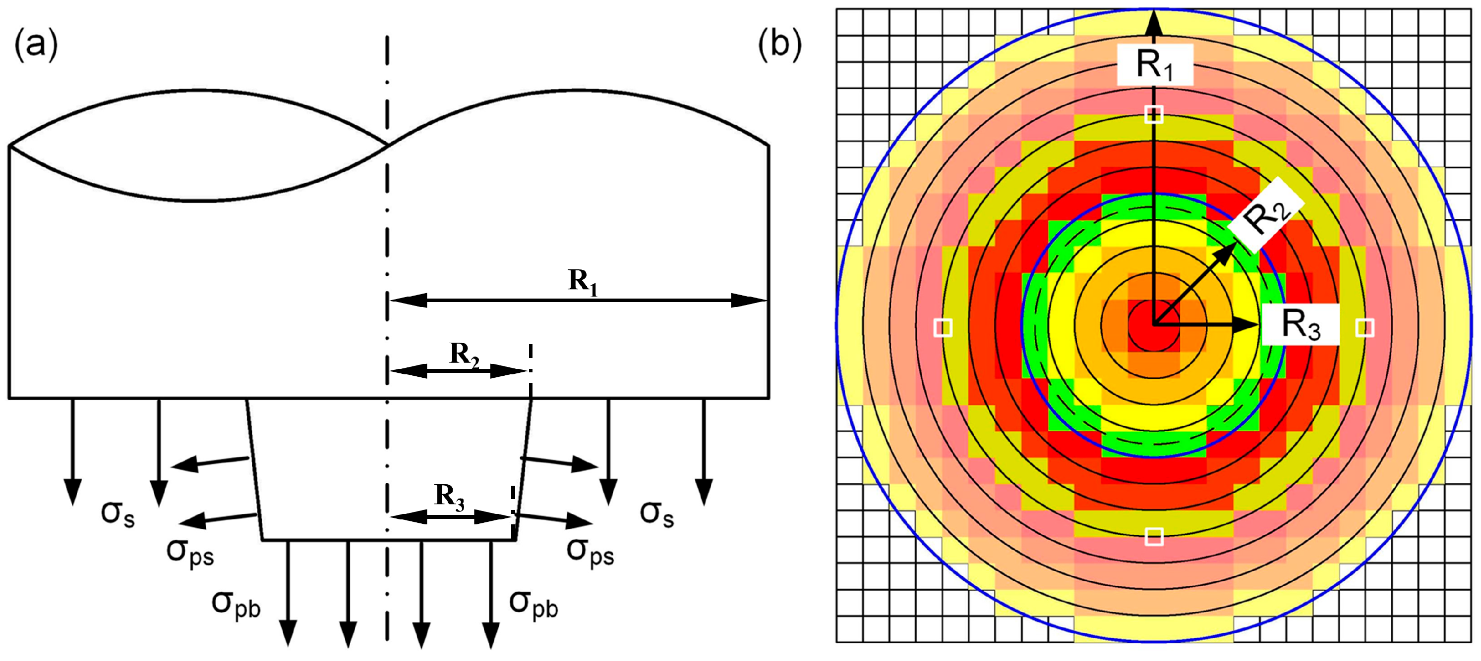
The welding force applied on the workpiece can be simply divided into three parts: σs from the shoulder, σps from the pin side, and σpb from the pin bottom, as illustrated in Figure 6a. The σps can be neglected when calculating the axial force because α is very small (sin α ≈ 0.1). In FSW, heat generation and transfer of any point on the shoulder or pin surface cannot be equal, and it is unreasonable to postulate that the stress from different parts will be distributed uniformly. In this work, the tool-acting area is segmented into 12 concentric circles, and the radius differences in the neighboring circles are all 1 mm. In each ring, the stress is selected as the yield strength at the average temperature of four nodes (white boxes), as shown in Figure 6b. Then, the forces are applied to the elements as the mechanical boundary condition, and the structural stress is calculated via the mechanical model. When evaluating the structural safety of the extrusions, the ratio of permissible stress to calculated stress should be greater than or equal to S1, and S1 should be 1.15 for each individual load case, according to European Standard EN 12263:2010 [26]. In accordance with fourth strength theory, the calculated stress (von Mises stress) of any point can be written as
where σc is the calculated stress, and σ1, σ2, and σ3 are the principle stresses along the x, y, and z directions, respectively. The permissible stress equals the yield strength σs,t at the actual temperature. So, the verification criteria for security can be described as
Figure 6.
Schematic view of (a) forces applied to the workpiece, (b) force distribution in the mechanical model.
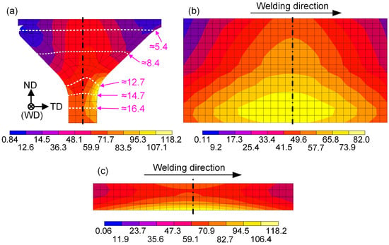
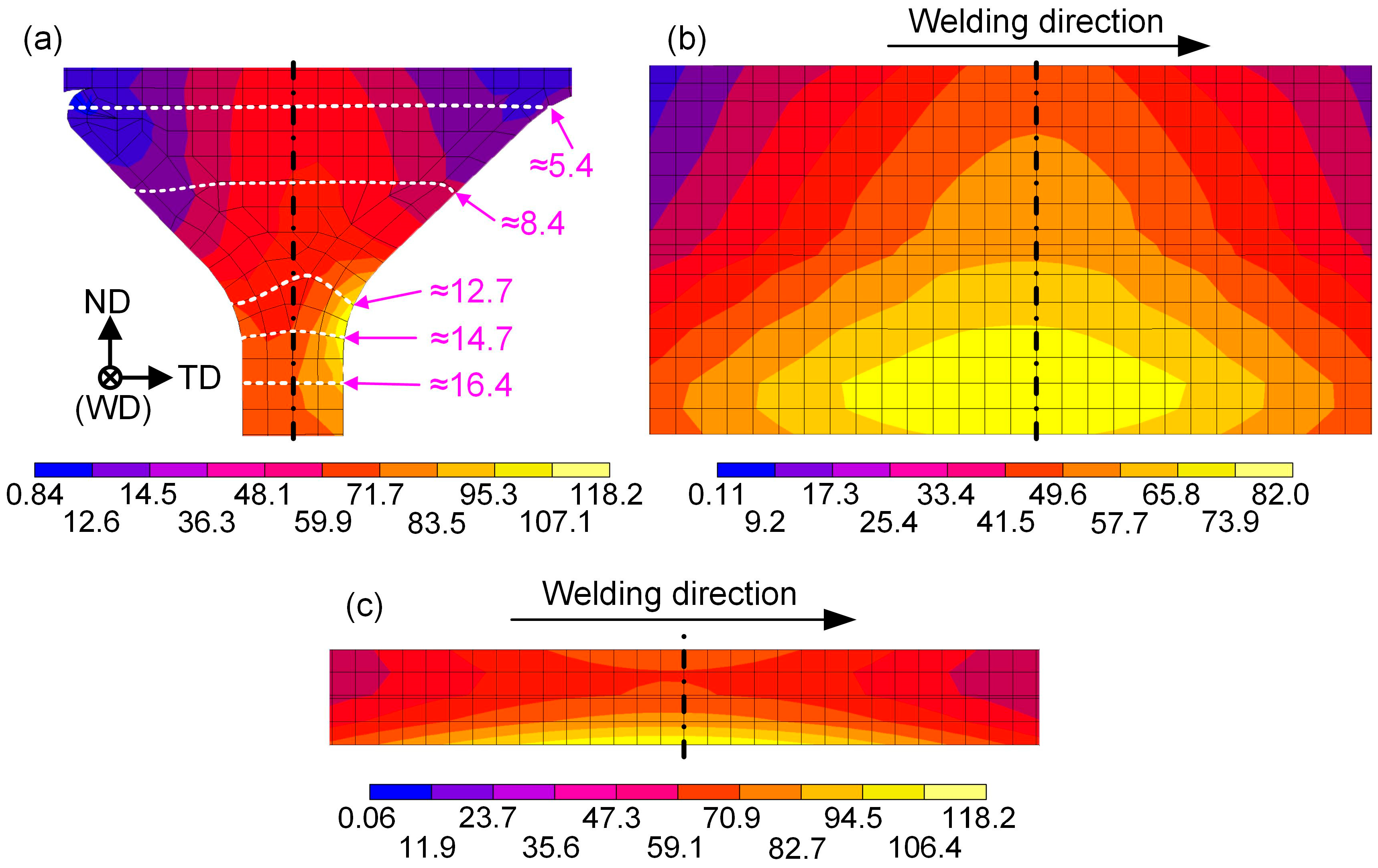
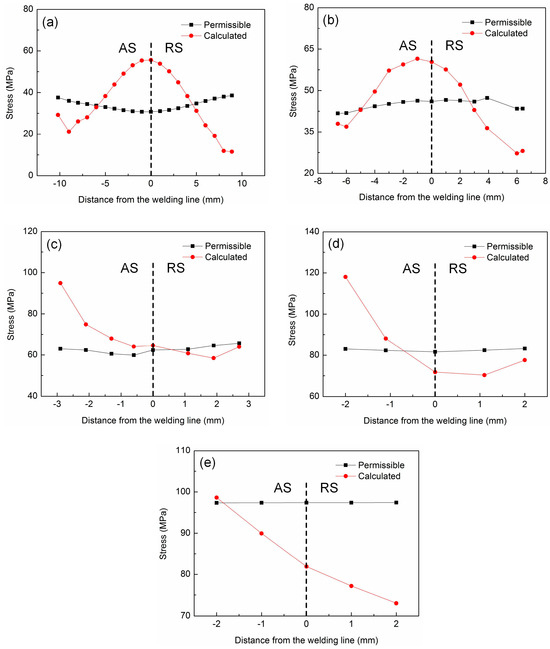
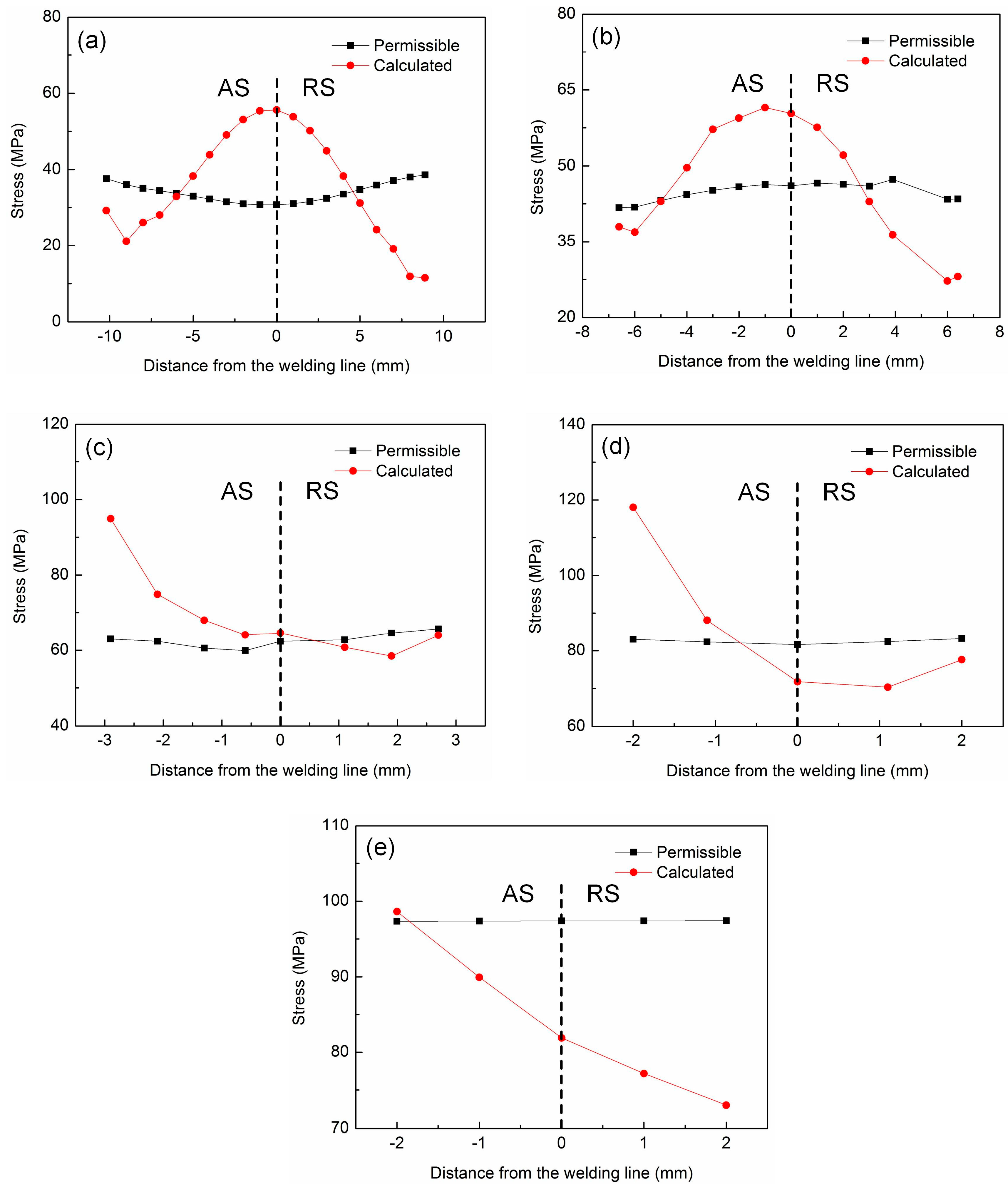
The distributions of calculated stress on various sections are displayed in Figure 7. It can be seen that the maximum calculated stress on the longitudinal section through the tool center is only 82.0 MPa. The high-stress zone is located at the arc transition region on the AS of the supporting rib, and the maximum value is about 118.2 MPa, which demonstrates that the existence of the arc causes a severe stress concentration. The auxiliary rib on the RS undertakes part of the applied welding force, and the calculated stress at the arc transition region on the RS of the supporting rib is reduced significantly. For purpose of performing a quantitative evaluation of the security of the current structure, the permissible and calculated stress of nodes versus the distance from the welding line at different depths from the top surface (shown in Figure 7a) are shown in Figure 8. At the same depth, the temperature difference among the nodes is small, and the permissible stress fluctuates within a very narrow range. With the increase in depth, the temperature of nodes with the same distance from the welding line apparently decreases due to the thermal diffusion and heat conduction, and there are obvious changes in the permissible stress. As for the calculated stress, the values of nodes near the welding line are higher than those far from the welding line before stress concentration occurs, while the values of nodes located at the arc transition region are much higher than those in other regions. As a result, at depths of 5.4 mm and 8.4 mm, the variation trends in permissible and calculated stress are opposite. The peak calculated stresses are all located at the center, and their values are 55.6 MPa and 61.5 MPa. The permissible stresses at the corresponding points are 30.7 MPa and 47.3 MPa. When the depth is 12.7 mm, the calculated stress begins to sharply increase due to the occurrence of stress concentration. The peak calculated stress reaches 94.9 MPa, and the corresponding permissible stress is 63.0 MPa. As the depth increases to 14.7 mm, the maximum stress is reached in the W4-R5 structure, calculated to have a value of 118.2 MPa, due to the most serious stress concentration, and it is located at the point of intersection between the arc and the line on the transverse section through the tool center. The permissible stress at this point is only 83.0 MPa, which is much lower than the calculated stress. At the depth of 16.4 mm, the peak calculated stress decreases to 98.6 MPa, and the permissible at the same point increases to 97.4 MPa. Overall, the calculated stresses for many nodes are higher than their permissible stresses, especially the nodes at a depth of 14.7 mm. This shows that the current structure cannot sustain the applied welding force, and some modifications should be made to increase the permissible stress and reduce the calculated stress of nodes. The former is required to lower the temperature of nodes, and the latter to enlarge the effective bearing area and weaken the stress concentration. Based on the above stress analysis, it can be seen that the width of the supporting rib W and the arc radius on the AS of the supporting rib R are the major factors that affect the permissible and calculated stress of nodes. So, increasing the dimension of W or R can not only directly enhance the bearing capacity of the structure but also increase the permissible stress of nodes because of the greater heat dissipation area. For convenience, the structure with a W of 4 mm and an R of 5 mm is denoted as the W4-R5 structure.
Figure 7.
Distribution of the calculated stress on various sections in the W4-R5 structure: (a) transverse section through the tool center, (b) horizontal section at a depth of 14.7 mm, (c) longitudinal section through the tool center.
Figure 8.
The permissible and calculated stresses versus distance from the welding line at various depths in the W4-R5 structure: (a) 5.4 mm, (b) 8.4 mm, (c) 12.7 mm, (d) 14.7 mm, and (e) 16.4 mm.
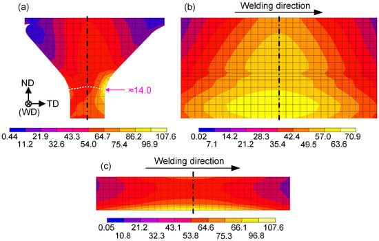
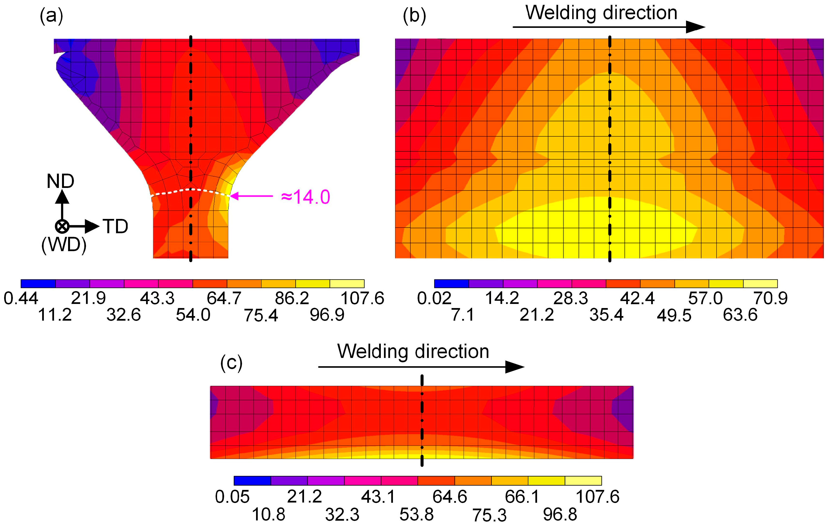
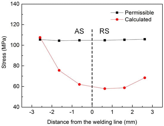
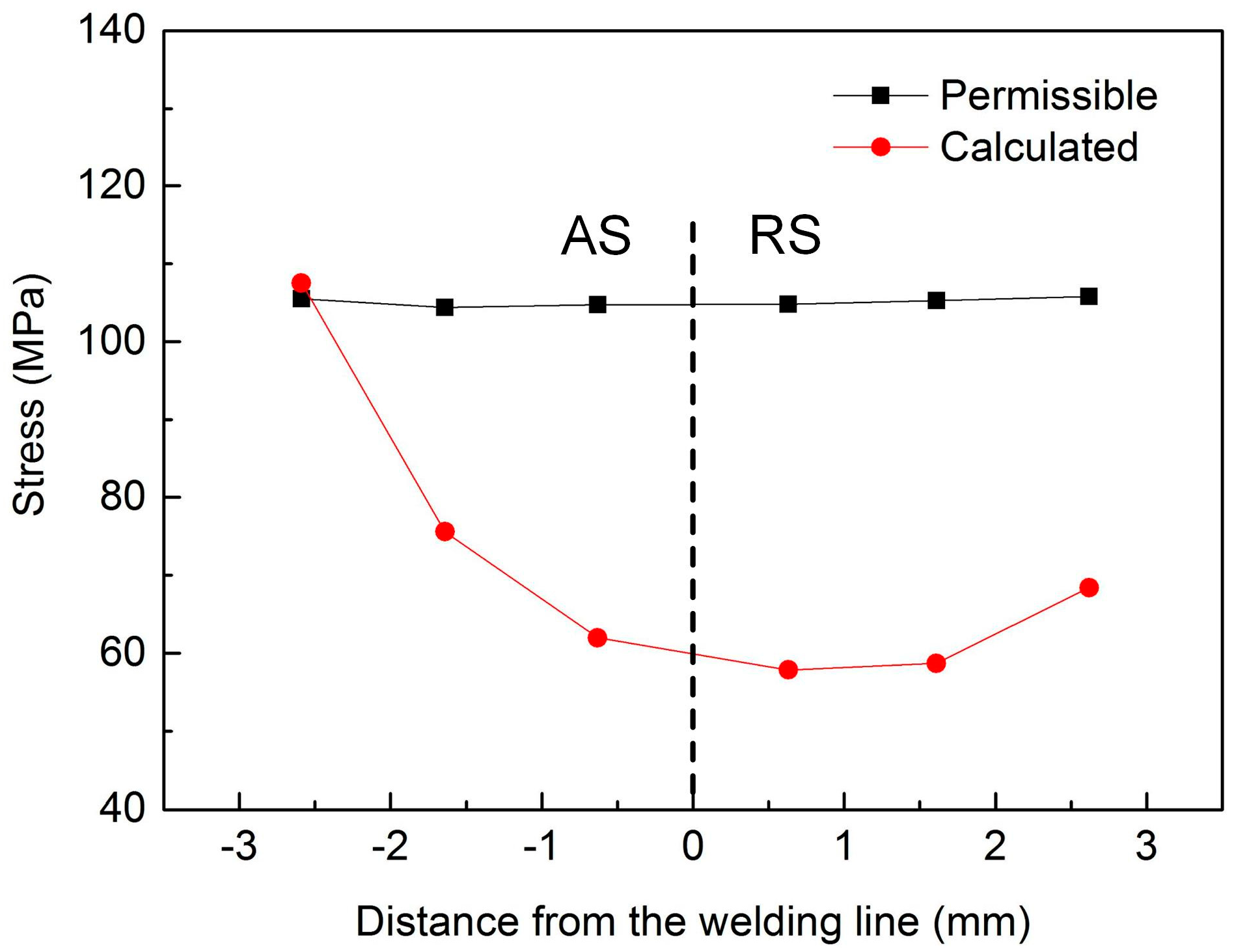
Figure 9 shows the distributions of calculated stresses on various sections in the W5-R5 structure. The most serious stress concentration in this structure is still at the point of intersection between the arc and line on the transverse section through the tool center, but the increase in W makes the point move outwards along the TD. The cross-sectional area of the initial overall structure is 3016 mm2, and that of W5-R5 is 3024 mm2. The increasing of the cross-sectional area reduces the maximal calculated stress from 118.2 MPa to 107.6 MPa. Figure 10 shows the permissible and calculated stresses of the nodes at a depth of 14.0 mm. The permissible stress of the node with a distance of −3 mm from the welding line increases to 105.5 MPa, which is almost equal to the maximal calculated stress. It is clear that increasing the W to 5 mm can improves the structural safety, but this modified structure is in a critical state, and it is hard to evaluate whether it is safe or not.
Figure 9.
Distribution of the calculated stress on various sections of the WR-R5 structure: (a) transverse section through the tool center, (b) horizontal section at a depth of 14.7 mm, (c) longitudinal section through the tool center.
Figure 10.
The permissible and calculated stresses versus distance from the welding line at a depth of 14.0 mm in the W5-R5 structure.
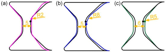
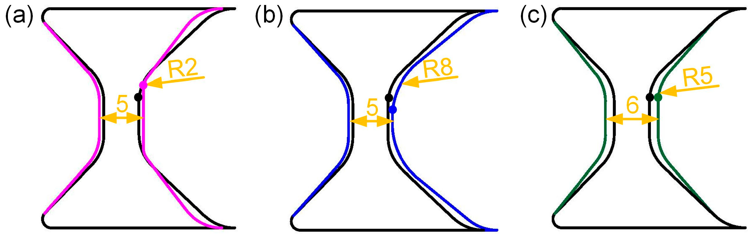
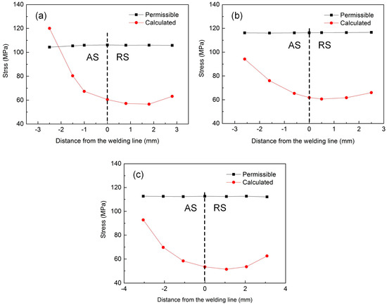
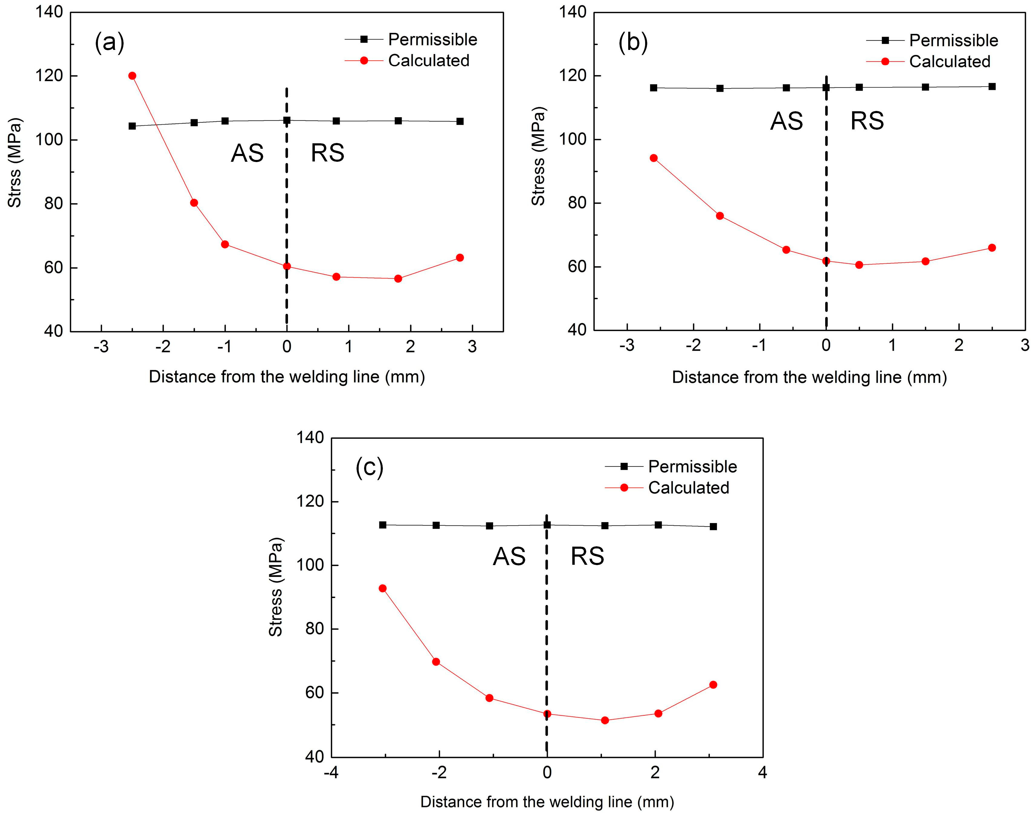
To study the influence of W and/or R on the permissible and calculated stress, three other modified structures, W5-R2, W5-R8, and W6-R5, are designed, and the local cross-section shapes of these modified structures and the initial structure are shown in Figure 11. The outline of the initial W4-R5 structure is shown with the black line, and lines with various colors are used to outline the modified structures. It is found that increasing W will make the maximal stress point move outwards along the TD, and increasing or decreasing R will make the maximal stress point move upwards or downwards along the ND. The cross-sectional areas of the W5-R2, W5-R8, and W6-R5 structures are 3024 mm2, 3048 mm2, and 3048 mm2, respectively. When the structural design changes, the depth of the point with the maximal calculated stress from the top surfaces also changes, and this depth is called depth 4. The nodal permissible and calculated stress of the modified structures at depth 4 in various modified structures are presented in Figure 12. It can be observed that the maximal calculated stress and the permissible stress at the same point in the W5-R2 structure are 120.1 MPa and 104.3 MPa, which demonstrates that the W5-R2 structure cannot meet the security requirement. With an increase in the W or R, the maximal calculated stress decreases dramatically. The maximal calculated stresses in W5-R8 and W6-R5 structures are only 94.2 MPa and 92.8 MPa, while the corresponding permissible stresses reach values of 116.2 MPa and 112.7 MPa. The results show that both the W5-R8 and W6-R5 structures can satisfy the security demand, and W6-R5 is finally selected as the optimal structure.
Figure 11.
The comparison of local cross-section shapes between the modified structures and initial W4-R5 structure: (a) W5-R2, (b) W5-R8, (c) W6-R5.
Figure 12.
The nodal permissible and calculated stresses versus distance from the welding line at depth 4 in different modified structures: (a) W5-R2, (b) W5-R8, (c) W6-R5.
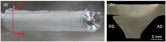
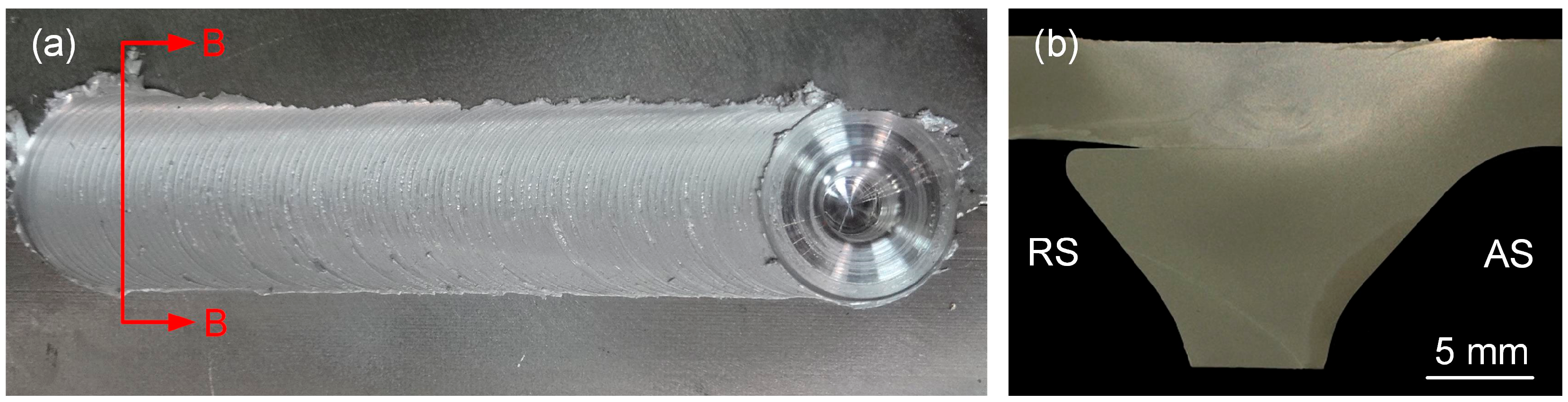
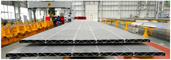
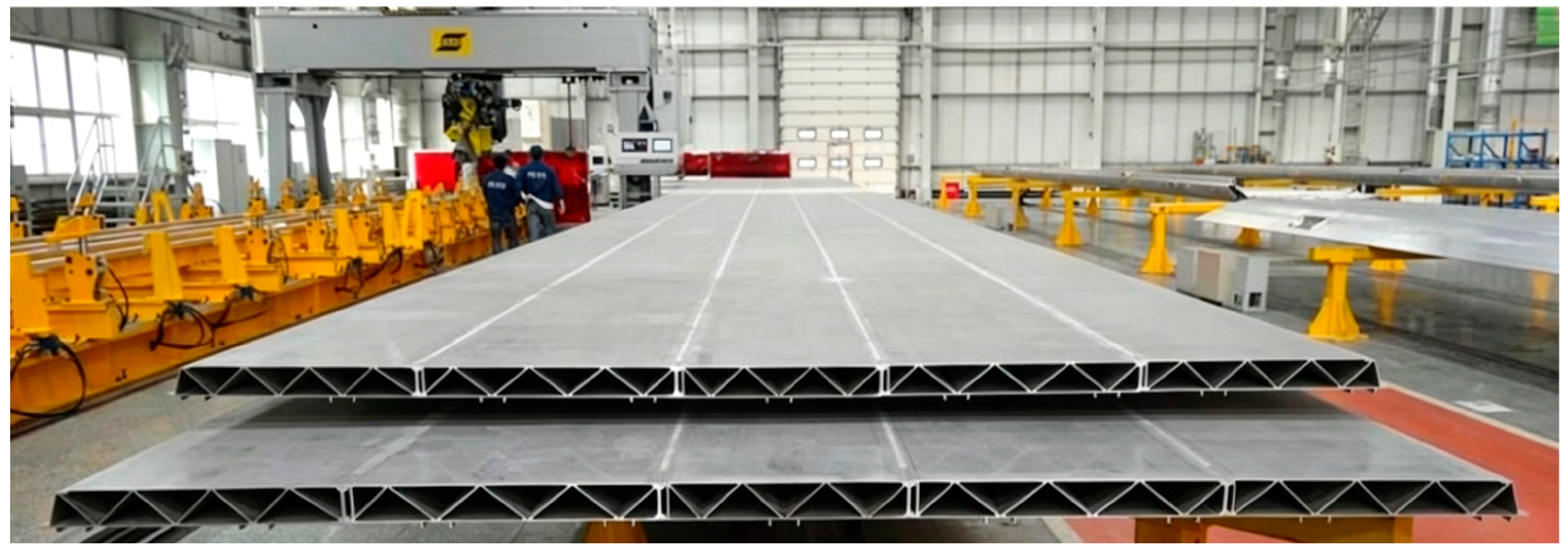
Then, the hollow extrusions were extruded and machined into welding samples, and the welding experiment was carried out to fabricate an FSW joint. The obtained joint was cross-sectioned perpendicular to the welding direction for metallographic analyses using an electrical-discharge cutting machine. The metallographic samples were polished using a diamond paste, etched with Keller’s reagent, and observed using an optical microscope. Figure 13 shows the surface appearance and macrostructure of transverse sections for the joint. Figure 13a shows that the weld is fine and uniform, and no surface defects or excessive welding flash can be observed. Figure 13b shows clearly that there are no internal defects such as voids or grooves in the joint. Furthermore, the supporting rib shows no macroscopic geometric deformation (e.g., bending, warping, or necking), indicating that the structure did not undergo global failure during the FSW process. It should also be noted that this structure has passed all necessary tests and has been used in the construction of a certain type of high-speed train, as shown in Figure 14.
Figure 13.
The obtained joint: (a) surface appearance, (b) cross-section of B-B in (a).
Figure 14.
The optimized structure applied to a certain type of high-speed train.
6. Conclusions
(1) Specialized structures for friction stir-welded hollow extrusions are designed in order to satisfy security and economy requirements.
(2) In the initial designed W4-R5 structure, the maximum calculated stress reaches a value of 118.2 MPa, and the corresponding permissible stress is only 83.0 MPa, which demonstrates that the initial structure cannot sustain the applied welding force.
(3) Four other modified structures, W5-R5, W5-R2, W5-R8, and W6-R5, are designed by changing the dimensions of W and/or R, and the W6-R5 structure is finally selected as the optimized structure through a comparison of the permissible and calculated stress and the cross-sectional area.
(4) Friction stir welding technology is successfully applied to 6005A-T6 hollow extrusions, and the obtained joints show a good surface and cross-sectional morphology.
Author Contributions
Conceptualization, X.L. and Y.L. (Yaozong Li); methodology, X.L., W.W. and Z.S.; software, Y.L. (Yanmo Li) and Y.L. (Yaozong Li); validation, X.L., P.L. and Y.L. (Yaozong Li); formal analysis, X.G.; investigation, X.L., Y.L. (Yanmo Li), X.G. and L.Z.; resources, W.W.; data curation, Y.L. (Yanmo Li), L.Z. and G.W.; writing—original draft preparation, X.L.; writing—review and editing, X.G., Z.S. and G.W.; visualization, P.L. and Z.S.; supervision, L.Z. and Z.S. All authors have read and agreed to the published version of the manuscript.
Funding
The work reported on in this paper was supported by the Xiamen Major Science and Technology Plan Projects (Future Industries): Research on Key Technologies of Lightweight Alloy Printed Circuit Heat Exchangers for Aviation Applications (Grant No. 3502Z20241034).
Data Availability Statement
The data presented in this study are available on request from the corresponding author due to data confidentiality.
Conflicts of Interest
Authors Xiangqian Liu, Wei Wang, Yanmo Li, Peiyue Li, Yaozong Li, Xiaoyi Guo, Linlin Zhang were employed by the company Luoyang Ship Material Research Institute. The remaining authors declare that the research was conducted in the absence of any commercial or financial relationships that could be construed as a potential conflict of interest.
References
- Yan, L.; Xu, H. Lightweight composite materials in automotive engineering: State-of-the-ar and future trends. Alex. Eng. J. 2025, 118, 1–10. [Google Scholar] [CrossRef] [Scilit]
- Wen, Z.; Jun, X. Advanced lightweight materials for Automobiles: A review. Mater. Des. 2022, 221, 110994. [Google Scholar] [CrossRef] [Scilit]
- Dubey, R.; Jayaganthan, R.; Ruan, D.; Gupta, N.K.; Jones, N.; Velmurugan, R. Energy absorption and dynamic behaviour of 6xxx series aluminium alloys: A review. Int. J. Impact Eng. 2023, 172, 104397. [Google Scholar] [CrossRef] [Scilit]
- Ren, S.; Wu, R.; Shi, X.; Liu, Z.; Cong, F.; Lu, L.; Han, Y.; Chen, Y.; Wang, Y.; Wang, G.; et al. Effect of different wire composition on microstructure and properties of welded joint of 6XXX extruded alloys. J. Mater. Res. Technol. 2024, 29, 872–880. [Google Scholar] [CrossRef] [Scilit]
- Ohba, H.; Ueda, C.; Agatsuma, K. Innovative vehicle-the “A-train”. Hitachi Rev. 2001, 50, 130–133. [Google Scholar]
- Du, C.; Wu, Y.; Xia, M.; Ren, X. Effect of welding speed on the microstructure, hardness, and fatigue performance of Al-Zn-Mg-Cu FSW joints. Mater. Charact. 2025, 230, 115684. [Google Scholar] [CrossRef] [Scilit]
- Koçar, O.; Anaç, N.; Adin, M.Ş.; Çavuş, E.C.; Akgül, I. Friction stir welding of dissimilar aluminum materials and investigation of surface quality. Mater. Today Commun. 2026, 51, 114739. [Google Scholar] [CrossRef] [Scilit]
- Trimble, D.; Monaghan, J.; O’Donnell, G.E. Force generation during friction stir welding of AA2024-T3. CIRP Ann.-Manuf. Techn. 2012, 61, 9–12. [Google Scholar] [CrossRef] [Scilit]
- Astarita, A.; Squillace, A.; Carrino, L. Experimental study of the forces acting on the tool in the friction-stir welding of AA 2024 T3 sheets. J. Mater. Eng. Perform. 2014, 23, 3754–3761. [Google Scholar] [CrossRef] [Scilit]
- Elangovan, K.; Balasubramanian, V.; Valliappan, M. Influences of tool pin profile and axial force on the formation of friction stir processing zone in AA6061 aluminium alloy. Int. J. Adv. Manuf. Technol. 2008, 38, 285–295. [Google Scholar] [CrossRef] [Scilit]
- Kawasaki, T.; Makino, T.; Todori, S.; Takai, H.; Ezumi, M.; Ina, Y. Application of friction stir welding to the manufacturing of next generation “A-train” type rolling stock. In Proceedings of the 2nd International Symposium on Friction Stir Welding, Gothenburg, Sweden, 27–29 June 2000. [Google Scholar]
- Shahri, M.M.; Sandström, R. Fatigue analysis of friction stir welded aluminium profile using critical distance. Int. J. Fatigue 2010, 32, 302–309. [Google Scholar] [CrossRef] [Scilit]
- Shahri, M.M.; Sandström, R.; Osikowicz, W. Critical distance method to estimate the fatigue life time of friction stir welded profiles. Int. J. Fatigue 2012, 37, 60–68. [Google Scholar] [CrossRef] [Scilit]
- Zhang, C.S.; Zhao, G.Q.; Chen, Z.R.; Chen, H.; Kou, F.-J. Effect of extrusion stem speed on extrusion process for a hollow aluminum profile. Mater. Sci. Eng. B 2012, 177, 1691–1697. [Google Scholar] [CrossRef] [Scilit]
- ASTM International. ASTM E3-11(2017); Standard Guide for Preparation of Metallographic Specimens. ASTM International: West Conshohocken, PA, USA, 2017.
- ASTM International. ASTM E407-07(2015); Standard Practice for Microetching Metals and Alloys. ASTM International: West Conshohocken, PA, USA, 2015.
- Wanjara, P.; Monsarrat, B.; Larose, S. Gap tolerance allowance and robotic operational window for friction stir butt welding of AA6061. J. Mater. Process. Technol. 2013, 213, 631–640. [Google Scholar] [CrossRef] [Scilit]
- Murakawa, H.; Sano, M.; Wang, J.C. Influence of root gap and tack weld on transverse shrinkage during welding. Trans. JWRI 2012, 41, 65–70. [Google Scholar]
- Wade, M.; Reynolds, A.P. Friction stir weld nugget temperature asymmetry. Sci. Technol. Weld. Join. 2010, 15, 64–69. [Google Scholar] [CrossRef] [Scilit]
- Zhang, T.Y.; Chen, H. Numerical simulation of laser welding for the unusual thickness aluminum alloy 6005A. J. Chang. Univ. Technol. 2011, 32, 173–177. [Google Scholar] [CrossRef]
- Schmidt, H.B.; Hattel, J.H.; Wert, J. An analytical model for the heat generation in friction stir welding. Model. Simul. Mater. Sci. Eng. 2004, 12, 143–157. [Google Scholar] [CrossRef] [Scilit]
- Schmidt, H.B.; Hattel, J.H. Thermal modelling of friction stir welding. Scr. Mater. 2008, 58, 332–337. [Google Scholar] [CrossRef] [Scilit]
- Vukčević, M.; Savičević, S.; Janjić, M.; Šibalić, N. Measurement in friction stir welding process. In Proceedings of the 15th TMT Conference, Prague, Czech Republic, 12–18 September 2011. [Google Scholar]
- Atharifar, H.; Lin, D.C.; Kovacevic, R. Numerical and experimental investigations on the loads carried by the tool during friction stir welding. J. Mater. Eng. Perform. 2009, 18, 339–350. [Google Scholar] [CrossRef] [Scilit]
- Hussein, A.S.; Thiru, S.; Izamshah, R.; Tahir, A.S.M. Unstable Temperature Distribution in Friction Stir Welding. Adv. Mater. Sci. Eng. 2014, 2014, 1–8. [Google Scholar] [CrossRef] [Scilit]
- European Committee for Standardization (CEN). EN 12263:1998; Steel—Determination of Retained Austenite—Magnetic Method. CEN: Brussels, Belgium, 1998.

Disclaimer/Publisher’s Note: The statements, opinions and data contained in all publications are solely those of the individual author(s) and contributor(s) and not of MDPI and/or the editor(s). MDPI and/or the editor(s) disclaim responsibility for any injury to people or property resulting from any ideas, methods, instructions or products referred to in the content. |
© 2026 by the authors. Licensee MDPI, Basel, Switzerland. This article is an open access article distributed under the terms and conditions of the Creative Commons Attribution (CC BY) license.