Article

Microstructure and Mechanical Properties of Al-Mg-Zn-Er-Zr Alloy via Multi-Pass Metal Inert Gas (MIG) Welding

1
State Key Laboratory of Materials Low-Carbon Recycling, Beijing University of Technology, Beijing 100124, China
2
Northeast Light Alloy Co., Ltd., Harbin 150060, China
*
Authors to whom correspondence should be addressed.
Metals 2026, 16(3), 286; https://doi.org/10.3390/met16030286
Submission received: 6 January 2026 / Revised: 18 February 2026 / Accepted: 24 February 2026 / Published: 3 March 2026
(This article belongs to the Special Issue Advances in Welding of Metallic Materials)

Abstract

The microstructure and mechanical properties of the joint of a novel Al-Mg-Zn-Er-Zr alloy fabricated by multi-pass MIG welding using ER5E61 filler wire were investigated first. The results show that multi-pass MIG welding induces heterogeneous grains in the weld metal: equiaxed grains, columnar grains, and cover-pass feather-like grains. The weld metal exhibits coarse grains (45.81 ± 19.68 μm), a high proportion of high-angle grain boundaries (83.3%), and a low dislocation density compared with the base metal. The joint achieves 316 MPa ultimate tensile strength, 10.5% elongation, and 0.80 joint efficiency with minimum hardness (77.2 HV) in the weld metal. Strengthening mechanism analysis reveals that joint softening mainly stems from the disappearance of deformed structure, reduced dislocation density, and the coarsening and reduction in Al3(Er, Zr) nanophases. Diffuse precipitation of the Al3(Er, Zr) nanophases (19.61 nm, 0.53%) under multi-pass MIG welding compensates for the softening of the welded joint, leading to the retention of high tensile strength despite marked hardness loss, thus demonstrating effective strength preservation.

1. Introduction

Al-Mg alloys have been widely applied in automotive manufacturing, aerospace, and shipbuilding industries owing to their low density, corrosion resistance, and excellent weldability—their application as structural materials in corrosive marine environments is particularly prominent [1,2,3]. Al-Mg alloys cannot be strengthened via heat treatment, since the main alloying element, Mg, cannot be dispersed. The main methods of strengthening are solid solution strengthening [4,5] and deformation strengthening [6,7].
Over the past three decades, researchers have been dedicated to developing high-strength Al-Mg alloys to address the growing application demands. Nie et al. [8] obtained novel Al-Mg-Er-Zr alloys with tensile strengths exceeding 400 MPa by adding trace Er and Zr elements to introduce Al3(Er, Zr) second phases with an L12 structure that exhibited coherent with the Al matrix. Recently, Gao et al. [9] incorporated Zn into Al-Mg-Er-Zr alloys, triggering the formation of a stable Al-Mg-Zn ternary phase replacing the β phase in the novel Al-Mg-Zn-Er-Zr alloy, which improved corrosion resistance while increasing alloy strength. This novel Al-Mg-Zn-Er-Zr alloy overcomes the long-standing trade-off between high strength and excellent corrosion resistance that constrains conventional Al-Mg alloys.
Welding is a critical manufacturing process for applying Al-Mg-Zn-Er-Zr alloys, especially in large-scale ship hull structural components, where thick-plate welding technology is of particular importance. Conventional welding techniques for aluminum alloys mainly include metal inert gas (MIG) welding [10,11], laser welding [12], and friction stir welding (FSW) [13,14]. Among these, MIG welding is widely used for its excellent quality, high efficiency, and low cost [15], but it faces a key challenge in Al-Mg alloy welding: joint softening.
This softening is primarily attributed to the weakening in overall grain boundary strengthening (Hall–Petch effect) caused by grain coarsening, a reduction in solid solution strengthening from element Mg volatilization, and the loss of the dispersion strengthening due to the dissolution of the second phase during welding [16,17,18]. To address the above issues, incorporating microalloying elements (Er, Zr, and Sc) to metal fillers has proven effective [19,20]. Yang et al. [21] refined the grain size from 117 μm to 33 μm and increased fusion zone microhardness by 10 HV via Er/Zr addition. Wang et al. [17] used high-Mg ER5E61 wire for MIG welding of Al-Mg-Er-Zr alloys, achieving a welded joint with an ultimate tensile strength (UTS) of 337.5 MPa and a joint efficiency of 0.81, compensating for the strength loss caused by Mg burn-off. However, strength degradation caused by the dissolution of second phases, such as Al3(Er, Zr) in the WM during the rapid solidification process, remains an unavoidable issue in numerous studies on Al-Mg-Er-Zr alloy welding [17,22].
Compared with thin plates, thick plates are more prone to defects like porosity, incomplete fusion, and joint softening during welding. Thus, thick-plate welding requires careful consideration of welding heat input, groove design, pass design, etc. Gao et al. [23] mitigated welding defects and improved joint quality by preheating before welding and adjusting heat input, increasing tensile performance by 57.6%. Jiang et al. [24] found that multiple welding thermal cycles increased the precipitation of strengthening phases from 0.43% to 0.93% and improved tensile strength by 11.3 MPa and elongation by 1.7%.
Thus, it is anticipated that multiple thermal cycles in MIG welding may promote nanophase precipitation to compensate for joint softening in Al-Mg-Zn-Er-Zr alloys. This hypothesis is particularly relevant when contrasting with single-pass welding. According to recent literature reviews [17,18,22], the rapid cooling feature of single-pass welding inhibits the reprecipitation of Al3(Er, Zr) phases, thereby impeding the full exertion of the dispersion-strengthening effect. However, there have been no reports on multi-pass MIG welding of thick-plate Al-Mg-Zn-Er-Zr alloys, and the complex microstructural evolution of such joints, especially softening mechanisms induced by strengthening phase dissolution, remains unclarified.
This study focuses on multi-pass MIG welding of 20 mm-thick Al-5.83Mg-0.84Zn-0.17Er-0.12Zr alloy plates using ER5E61 filler wire. It employs techniques including electron back-scattered diffraction (EBSD) and transmission electron microscopy (TEM) to investigate the effects of multi-pass MIG welding on the microstructure and mechanical properties of welded joints, while clarifying the underlying joint-softening mechanism.

2. Materials and Methods

2.1. Materials and MIG Welding Experiment

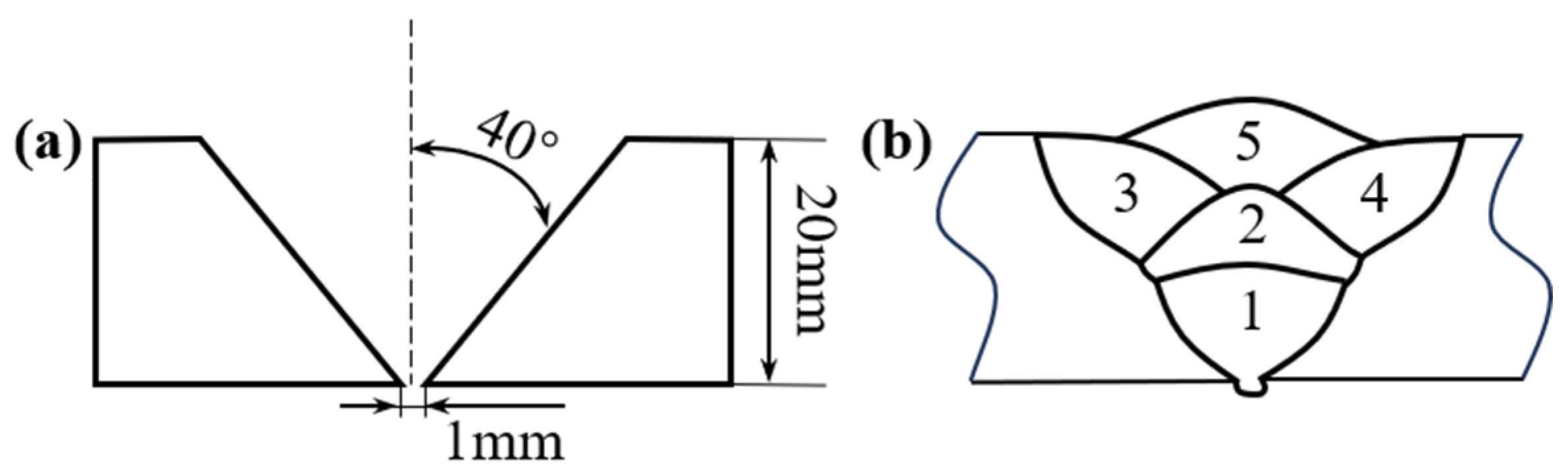
The 200 mm × 100 mm × 20 mm rolled plates of Al-5.83Mg-0.84Zn-0.17Er-0.12Zr alloy in H112 temper were applied as the base metal (BM), and Ø1.6 mm ER5E61 filler wire was selected as the filler material for multi-pass MIG welding. The chemical composition of the BM and filler wire is shown in Table 1. The surface of the BM samples was mechanically ground and chemically cleaned to remove oxide films and impurities before welding. Butt joints were achieved by combining Fronius TPS/TS-5000 MIG equipment with ABB IRB1400 robots. The schematic of the MIG welding device is illustrated in Figure 1, with the welding direction perpendicular to the rolling direction (RD). The groove design and build-up welding design are shown in Figure 2. A groove angle of 40° was adopted with a 1 mm root gap, and the welding process consisted of one root pass, three filling passes, and one capping pass. Pre-welding temperature and interpass temperature were maintained between 60 and 100 °C. Based on preliminary welding tests, the optimized welding parameters are as follows: root pass current of 220 A, fill pass current of 240 A, capping pass current of 230 A, welding voltage of 21.6 V, and welding speed of 6.0 mm/s. And 25 L/min of 99.999% ultra-high purity argon was used as a shielding gas during welding.

2.2. Microstructural Observation and Mechanical Testing

In this experiment, a BX51M metallographic microscope (Olympus Corporation, Tokyo, Japan) was employed to observe the grain size and microstructure morphology of the joint. The metallographic sample was ground successively with 800-, 2000-, and 5000-grit sandpaper, then polished with 1.5 μm diamond paste to achieve a scratch-free mirror surface. After installation and mechanical polishing, the cross-sectional samples were anodically etched with a solution (5 mL H3BO3 + 20 mL HF + 475 mL H2O) at a voltage of 15 V, a current of 0.6 A, and a time of 70 s. And grain size statistics were calculated using Image J 1.52p software.
Phases and elemental distribution studies of MIG-welded joints were characterized with a SU8020 scanning electron microscope (SEM, Hitachi High-Tech Corporation, Tokyo, Japan) equipped with an energy dispersive spectrometer (EDS). A Bruker D8 Advance X-ray Diffractometer (XRD, Bruker AXS GmbH, Karlsruhe, Germany) was also employed to analyze phase composition. Electron back-scattered diffraction (EBSD) analysis was carried out in a Quanta 650 FEG SEM (FEI Company, Hillsboro, OR, USA) equipped with a Nordlys Nano EBSD system. The EBSD samples were mechanically ground and polished, then electrolytically polished for 15–17 s in an electrolyte solution (HClO4:C2H5OH = 1:9) at 20 V and 0.6 A. Scanning step size is 2 μm. EBSD data were evaluated by the OIM Analysis 7.2 software. The morphology of the nanoprecipitates was observed with a FEI Talos F200X-G2 transmission electron microscope (TEM, Thermo Fisher Scientific, Hillsboro, OR, USA). Image J software was employed to analyze at least eight non-overlapping, representative TEM images, measuring the average diameter of precipitates and calculating their volume fraction using the area fraction method.
The microhardness of the joint was measured by a HVS-1000 microhardness tester (Laizhou Huayin Testing Instrument Co., Ltd., Laizhou, Shandong, China) under a 100 gf load applied for 10 s. Hardness distribution profiles were obtained by linear (or grid) point arrangement on the joint cross-section. The test point spacing was 0.5 mm, and the test results were averaged from three parallel specimens to ensure data reliability. Tensile tests of the joints were conducted on an MTS-SANSCMT5000 microcomputer-controlled electronic universal testing machine (MTS Systems (China) Co., Ltd., Jinan, Shandong, China) with a load speed of 1.0 mm/min at room temperature, following GB/T 228.1-2021 and GB/T 2651-2023 standards [25,26]. Three standard samples were prepared for the BM and welded joints, and the average value was calculated as the result of the tensile properties.

3. Results

3.1. Weld Appearance of the Welded Joint

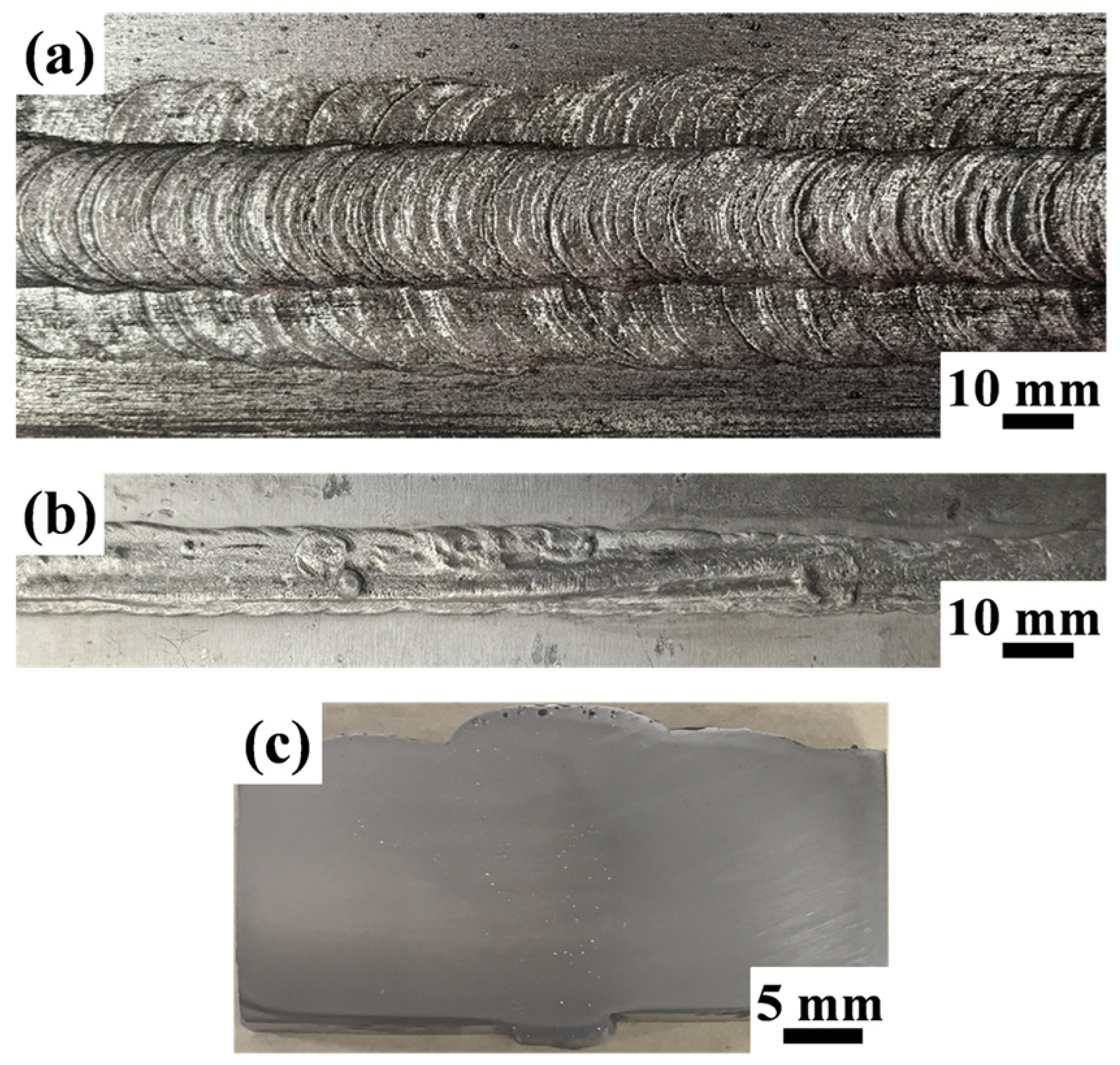
Figure 3 shows the weld bead formation of the Al-5.83Mg-0.84Zn-0.17Er-0.12Zr alloy in multi-pass MIG welding. A fully penetrated joint was obtained, with good weld formation and a uniform surface, displaying obvious fish-scale patterns and metallic luster. This indicated a stable welding process and effective shielding gas protection. And the weld seam exhibited no obvious cracks, lack of fusion, or other defects.

3.2. Optical Microstructure

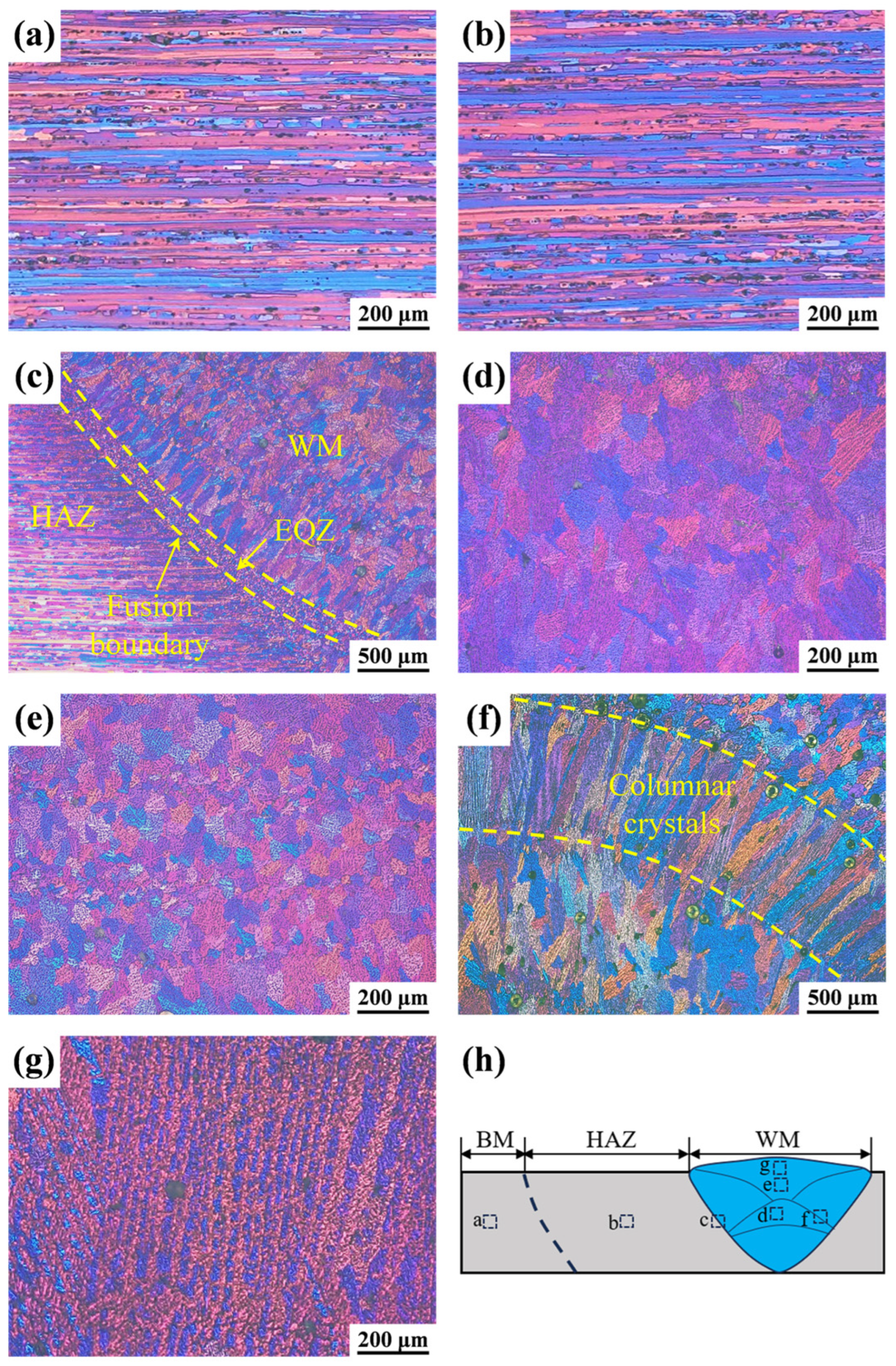
Figure 4 illustrates the microstructure of different regions of the multi-pass MIG-welded joint of the Al-5.83Mg-0.84Zn-0.17Er-0.12Zr alloys after anodic etching. The metallographic observation location is shown in Figure 4h. Based on the microstructural differences, the welded joint can be divided into three regions of the BM, the heat-affected zone (HAZ), and the weld metal (WM). Due to the rolling process of the aluminum alloy base material, elongated grains along the rolling direction (RD) with fine recrystallized equiaxed grains were observed in the BM (Figure 4a). Average grain width was 15.8 μm, with an average aspect ratio of 5.9. Figure 4b shows the grain structure in the HAZ. Under the influence of the welding thermal cycle, grains coarsened compared to the BM. Average grain width increased to 18.4 μm, while the aspect ratio decreased to 4.5. Figure 4c reveals that a 100 μm-wide equiaxed grain zone (EQZ) formed along the fusion line, where grain sizes ranged from 10 to 20 μm. The EQZ is primarily attributed to heterogeneous nucleation on unmelted grain surfaces of the BM. Columnar crystals formed adjacent to the EQZ and at weld bead boundaries, as depicted in Figure 4c,f. Columnar crystals at the weld bead boundaries exhibited larger dimensions, with a maximum length of approximately 1 mm. Figure 4d reveals equiaxed grains were evenly distributed with an average size of 45 μm in the WM. The equiaxed grains at the cover weld were rather fine, with a minimum size of 20 μm in Figure 4e. And feather-like crystals were only observed on the surface of the cover weld (Figure 4g), which were remelted and disappeared in the internal passes.

3.3. Phase Composition

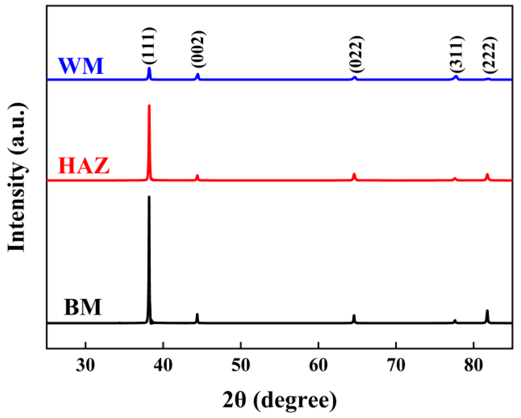
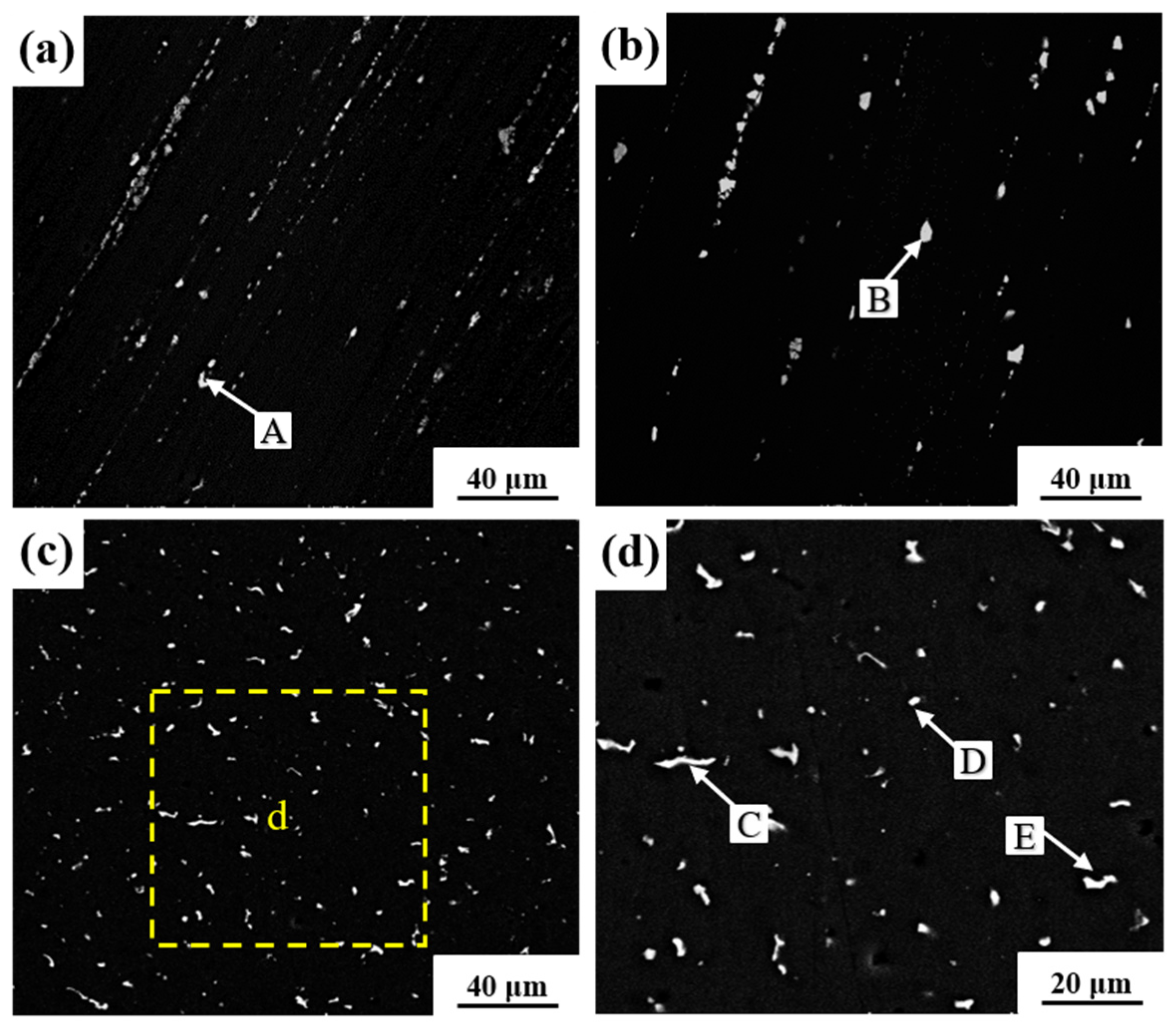
Back-scattered electron (BSE) images of the multi-pass MIG-welded joint regions for Al-5.83Mg-0.84Zn-0.17Er-0.12Zr alloy are shown in Figure 5, with semi-quantitative EDS analysis results (marked “A” to “E”) listed in Table 2. In the aluminum matrix (dark zone), numerous irregular white or gray precipitates were observed to be distributed in banded patterns along the grain boundaries. Some of these phases exhibited fracture features induced by rolling deformation, as evidenced in the BSE image of the BM (Figure 5a). Based on semi-quantitative EDS results of phase “A”, these phases were identified as ternary Al6(Mn, Fe) primary phases formed by Fe adsorption on Al6Mn, with the presence of the Al3Mg2 phase [27]. In the HAZ (Figure 5b), EDS analysis of phase “B” showed that its composition was essentially identical to the BM primary phases, with no apparent changes in morphology or distribution except for coarsening. In the WM, phases showed uniform distribution and smaller dimensions than those in the BM and HAZ due to the agitation of the fusion pool and rapid solidification. Figure 5d presented a local magnification of the WM in Figure 5c. EDS analysis of points “C”, “D”, and “E” indicated that these phases were mainly composed of Al, Mg, Mn, Fe, and Er. It was proposed that these phases contained Al3Er and Al3Mg2 phases in addition to ternary Al6(Mn, Fe) phases [18,21]. Al3Er phases may adsorb some Mg atoms during their formation and growth, eventually forming multi-eutectic phases [28]. The diffraction patterns (Figure 6) consisted of five distinct Bragg reflection peaks, corresponding to the Miller indices (111), (002), (022), (311), and (222), indexing to the face-centered cubic (fcc) α-Al matrix. The BM and HAZ exhibited a stronger (111) peak, indicating that the rolling process induced a (111) crystallographic preferred orientation. The WM exhibited a uniform weak peak, stemming from as-cast non-oriented grains. Precipitates such as Al3(Er, Zr) exhibit weak diffraction signals owing to their low volume fractions and nanoscale sizes, which are masked by the intense α-Al matrix peaks.
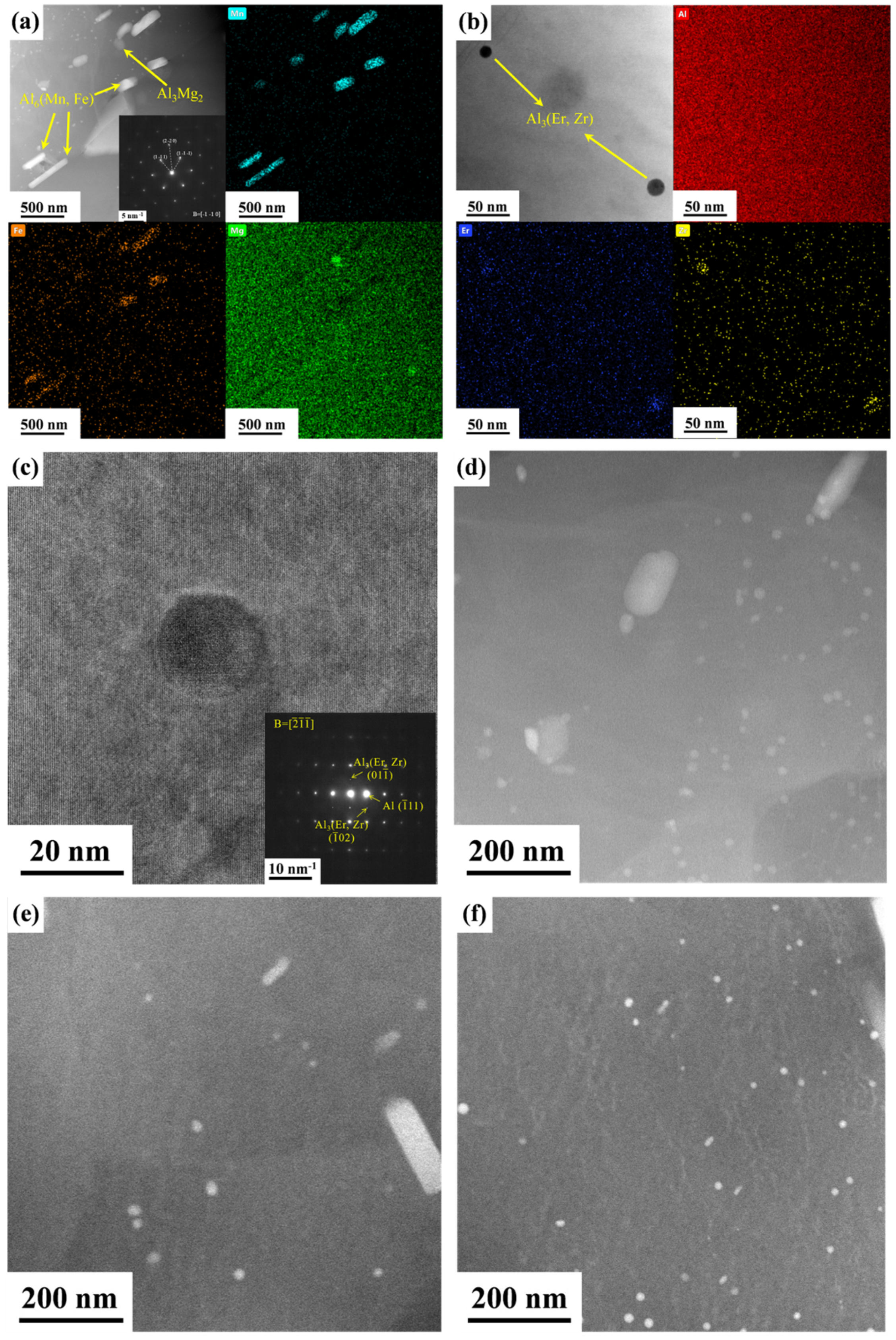
The existence of second phases is further confirmed by TEM observations and EDS analysis in Figure 7. The bright field image (Figure 7a) reveals numerous rod-like or blocky precipitates. Based on EDS surface scanning analysis, these phases were primarily rich in Mn and Fe, constituting Al6(Mn, Fe) phases with a maximum length of 400 nm. Additionally, spherical phases enriched in Mg were identified as Al3Mg2 phases, with an approximate size of 60 nm. The hindrance of secondary dislocation motion contributes to the enhancement of material strength and hardness [29]. These precipitates were coarsened in size and sparsely distributed, exerting a negligible strengthening contribution. A large number of small, dispersed spherical phases were also discovered. After magnification and EDS analysis (Figure 7b), these phases were enriched in Er and Zr. Combined with HRTEM image and corresponding electron-diffraction pattern (Figure 7c), it was confirmed that these spherical nanoprecipitates were secondary Al3(Er, Zr) phases, with sizes ranging from 10 to 20 nm. These phases contribute to the dispersion strengthening of the welded joint [20,21,30]. Figure 7d–f show the distribution of Al3(Er, Zr) nanophases in different areas of the welded joint. Compared to the cover weld pass (WM-2), the second weld pass (WM-1) exhibits a significantly increased precipitation of Al3(Er, Zr). The Al3(Er, Zr) phases in the BM exhibit a finer dispersion. Previous study has demonstrated that a few primary Al3(Er, Zr) nanophases are formed in the WM during single-pass welding, with more Er and Zr atoms solid-solving into the matrix [22], which is consistent with the precipitation of Al3(Er, Zr) phases observed in the final pass. The average diameters of the Al3(Er, Zr) nanophases in the BM and WM were determined to be 15.74 nm and 19.61 nm, with volume fractions of 0.77% and 0.53% respectively.

3.4. Grain Size and Misorientation Angle Distribution

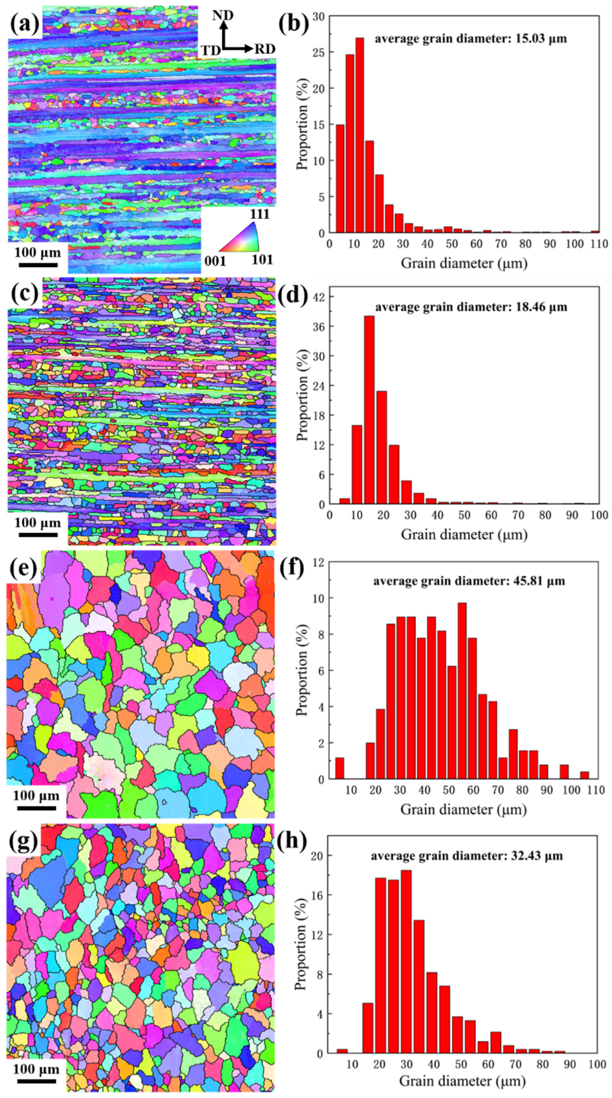
Figure 8a,b presents the inverse pole figures (IPFs) map and grain size distribution of the BM. The BM mainly consisted of elongated grains with distinct preferred orientation, interspersed with a small amount of recrystallized grains. The average grain width was 15.03 ± 3.21 μm. Compared with the BM, the HAZ exhibited a significant increase in recrystallized grains and a weakening of preferred orientation, though a striped distribution remains in Figure 8c. The grain width coarsened to 18.46 ± 4.57 μm. Figure 8e,g shows the microstructure of the second weld pass (WM-1) and the cover weld pass (WM-2) respectively, featuring randomly oriented equiaxed grains with no obvious preferred orientation. The grain size distribution of the second weld pass was more uneven, with the vast majority of grains (97.67% of the total) ranging in size from 17.85 μm to 88.73 μm. The average grain size was 45.81 ± 19.68 μm, with a maximum grain size of 105.4 μm. The equiaxed grain size and shape at the center of the cover weld were more uniform than those in the second weld pass, with grains smaller than 42.87 μm accounting for 91.24%, as shown in Figure 8h. And the average grain size was 32.43 ± 11.73 μm. This refinement can be attributed to the absence of subsequent thermal cycles and the enhanced heat dissipation at the weld surface, thereby suppressing grain growth. And the intermediate weld passes experience coarsening due to multiple thermal cycles [31].
Table 3 illustrates the misorientation angle distribution and recrystallized area fraction of the BM, HAZ, and WM. Conventionally, grain boundaries with misorientation angles between 2° and 15° are defined as low-angle grain boundaries (LAGBs), while those exceeding 15° are categorized as high-angle grain boundaries (HAGBs). The recrystallized area fraction is determined via grain orientation spread (GOS) analysis. In the BM, LAGBs constituted 71.0% of the total grain boundaries, serving as the dominant type. This is closely associated with the extremely low recrystallized area fraction (only 10.4%). By contrast, the proportion of HAGBs gradually increased in the HAZ and WM, reaching 83.3% and 87.4% in the latter, respectively. And the recrystallized area fraction of the WM exceeds 90%, indicating almost complete recrystallization. The increase in HAGBs is the result of fine recrystallized grains, whose nucleation and growth occur through the consumption of dislocations during the migration from LAGBs to HAGBs [32]. High HAGB content in welds primarily resulted from the equiaxed grain structure of the WM, which provided higher interface energy and promoted precipitate precipitation [33].

3.5. KAM and GND

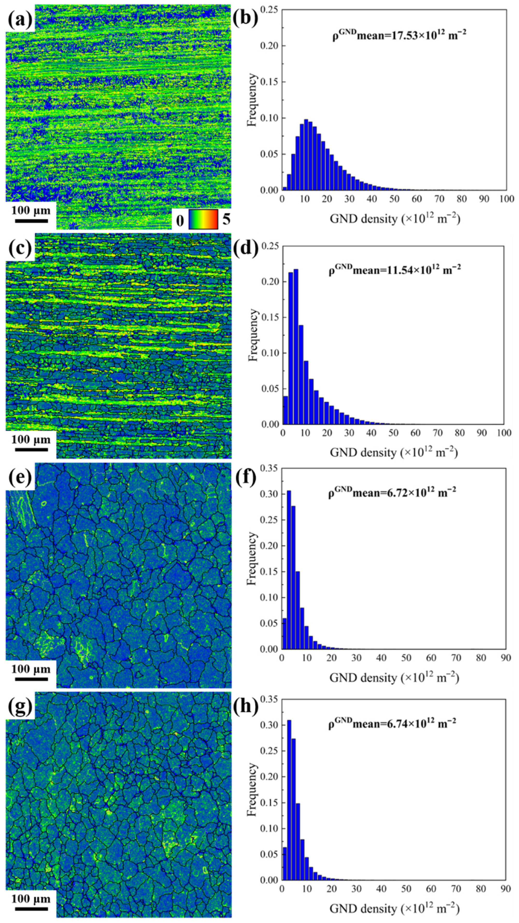
Kernel Average Misorientation (KAM) effectively reflects the local strain distribution in crystalline materials. Dislocation pile-up-induced lattice distortion intensifies with increasing dislocation density, and a larger orientation difference between adjacent regions corresponds to a higher KAM value [34]. The KAM value shows a strong correlation with the geometric necessary dislocation (GND) density in deformed grains. GNDs accumulate to maintain strain compatibility during deformation [35]. The BM was primarily composed of deformed grains (Figure 9a), exhibiting high KAM values. These deformed grains featured high strain and GND density, with an average GND density of 17.53 × 10¹² m−2 (Figure 9b). In Figure 9c, KAM green regions (representing high-strain areas) decreased significantly, which was attributed to recrystallization induced by welding thermal cycles. And the average GND density dropped to 11.54 × 10¹² m−2 (Figure 9d), with the reduction in dislocation density further driving the recrystallization process. For WM-1 and WM-2, KAM maps were almost entirely blue, a feature corresponding to the low local strain and GND density of equiaxed grains formed during solidification. Average GND densities of WM-1 and WM-2 show no statistically significant difference, measuring 6.72 × 10¹² m−2 and 6.74 × 10¹² m−2 respectively, as shown in Figure 9f,h. These results suggested that recrystallization weakened the dislocation strengthening of the WM, whereas the BM retained a stronger dislocation-strengthening effect due to its deformed structure.

3.6. Hardness Profile

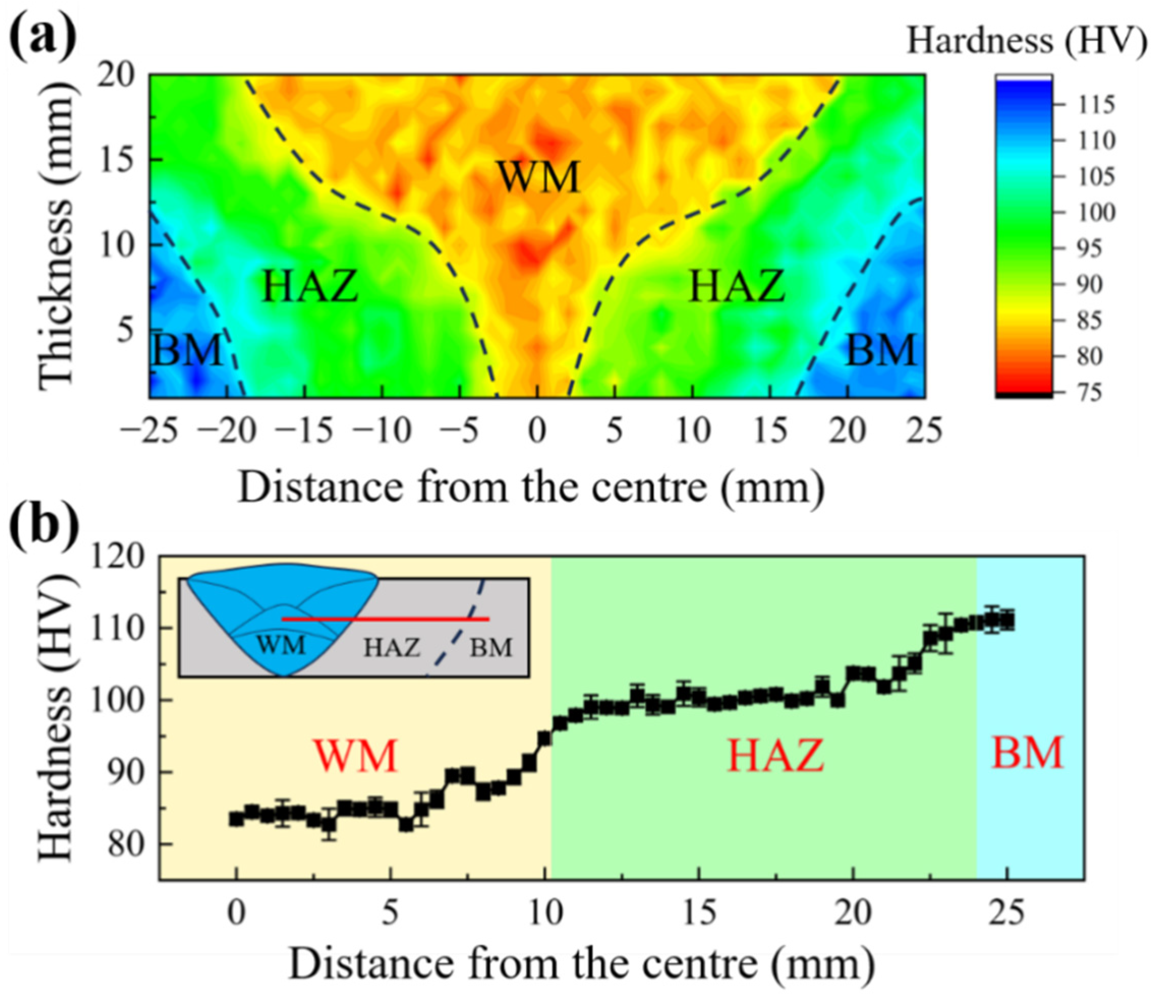
The hardness distribution at the cross-section of the multi-pass MIG-welded joint of Al-5.83Mg-0.84Zn-0.17Er-0.12Zr alloy is depicted in Figure 10. The microhardness correlates closely with grain refinement, following the Hall–Petch strengthening mechanism: finer grains enhance hardness by increasing grain boundary density to impede dislocation motion. In contrast, the microhardness of the BM is more significantly affected by work hardening during the rolling process, resulting in a microhardness range of 110.2–118.0 HV. After multi-pass MIG welding, the microhardness gradually decreased from the BM to the WM. The WM and HAZ of the welded joint softened. The HAZ showed intermediate hardness (95.4–109.3 HV), with softening linked to grain coarsening alongside secondary phase coarsening (Al6(Mn, Fe), Al3(Er, Zr)) and reduced dislocation density. The WM exhibited the lowest hardness (77.2–94.9 HV) in the welded joint. This can be attributed to the rapid melting and cooling of the WM under welding thermal input, resulting in the formation of a coarse-grained structure (Figure 8), the coarsening and dissolution of precipitated phases (Figure 7), and dislocation annihilation (low KAM values in Figure 9). These factors collectively led to the complete loss of the work-hardening effect. This is consistent with previous studies [18,36].

3.7. Tensile Properties and Fracture Behavior

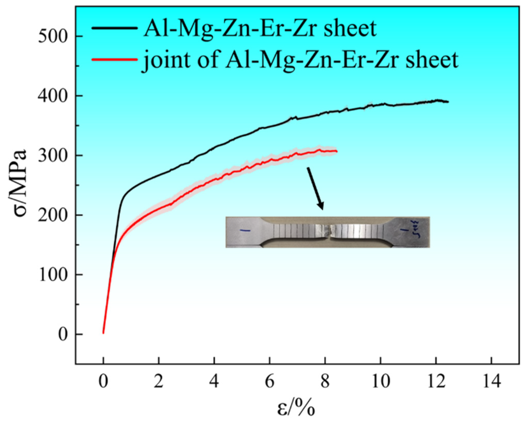
The tensile properties of the base material and the welded joint are presented in Table 4, and the engineering stress–strain curves are shown in Figure 11. The welded joint fractured in the WM, with no initiation or propagation observed in the BM or the HAZ. This indicates that the WM is the weakest area of the welded joint, which aligns with the joint-softening phenomenon discussed above. The BM exhibits an average tensile strength of 394 MPa and a post-fracture elongation of 14.0%. In contrast, the welded joint shows a slight reduction in average tensile strength to 316 MPa, accompanied by a post-fracture elongation of 10.5%. The joint efficiency of the welded joint (the ratio of the tensile strength of the welded joint to that of the base material) reaches 80%, which is comparable to the 81% obtained via single-pass welding. Coarse as-cast grains from weld remelting and solidification during welding cause joint property degradation, while the dispersion strengthening of Al3(Er, Zr) nanophases in the WM ensures a relatively high tensile strength of the joint. These nanophases enhance the WM work-hardening rate via the Orowan mechanism and delay tensile plastic instability. Nevertheless, when deformation reaches a certain degree, microvoid coalescence dominated by coarse grain boundaries prevails in the WM and ultimately induces fracture.
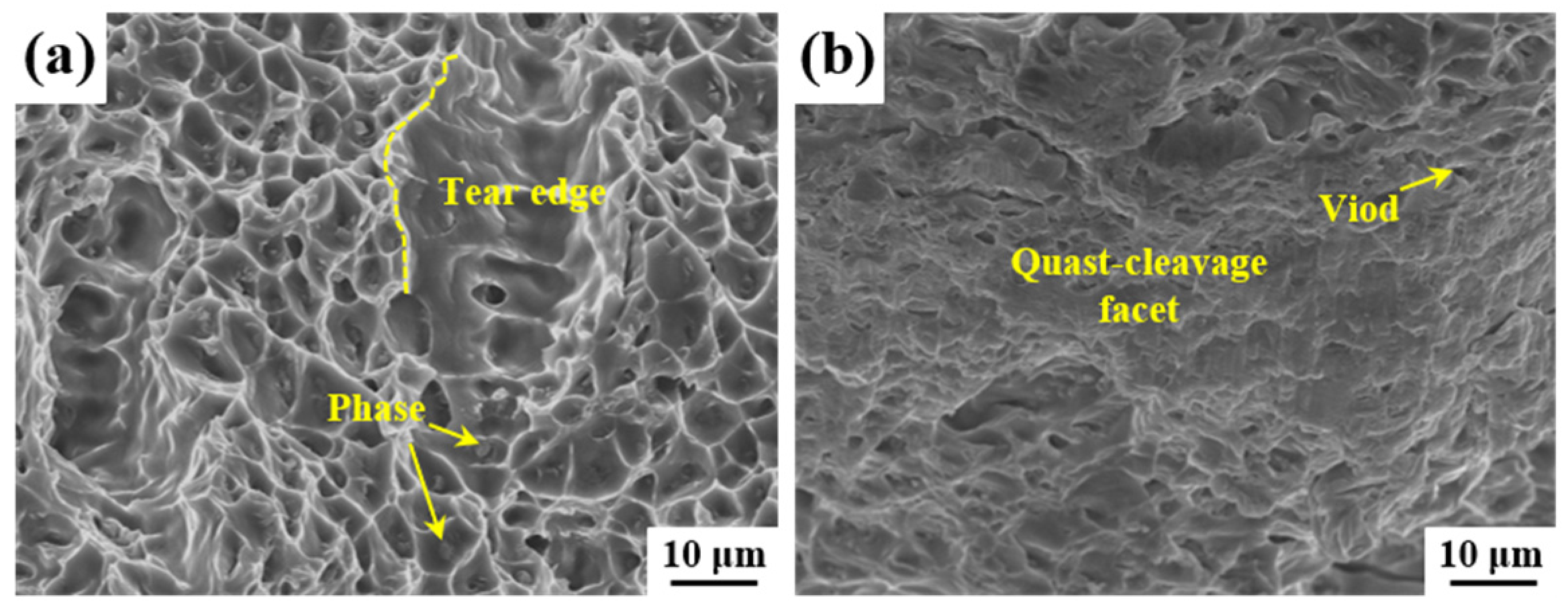
The fracture surface of the welded joint exhibits distinct ductile fracture characteristics, characterized by numerous ductile dimples with a diameter range of 3–7 μm (average ~5 μm), prominent tear edges, and the presence of second phases within the dimples, as shown in Figure 12a. At another location on the fracture surface in Figure 12b, quasi-cleavage facets and voids were observed, indicating brittle fracture characteristics. The brittle region accounts for 15–20% of the entire fracture surface. The presence of pores causes stress concentration points, promoting crack initiation and accelerating specimen fracture. Consequently, the welded joint exhibits a mixed ductile–brittle fracture mode.

4. Discussion

4.1. Microstructural Evolution

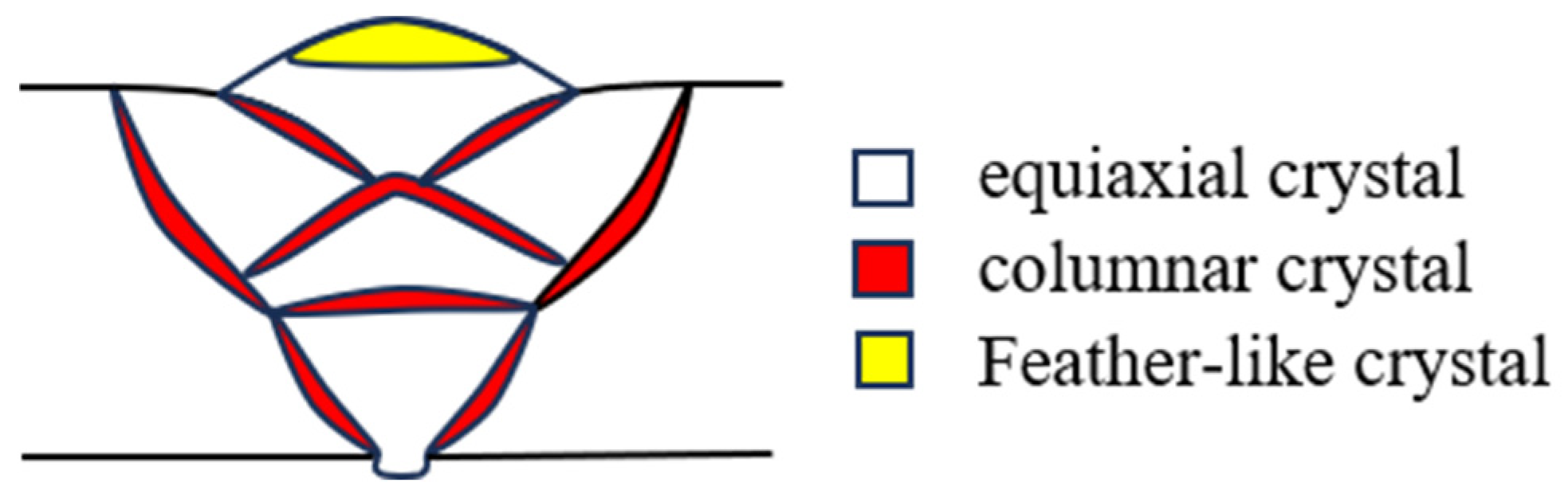
Microstructural observations reveal that the WM exhibits heterogeneous grain morphology: equiaxed grains, coarse columnar grains, and feather-like grains, as illustrated in Figure 13. Rapid cooling and solidification at the melt pool edge, combined with Mg and Zn segregation, cause compositional undercooling that promotes nucleation. Concurrently, stored energy from rolling deformation of the parent material accelerates dynamic recrystallization, forming an EQZ (width of ~100 μm and grain size of 10–20 μm) along the fusion line [37]. In previous studies, the EQZ in aluminum alloy welds containing Er and Zr showed negligible epitaxial growth owing to the limited compositional undercooling and the promotion of heterogeneous nucleation by Al3(Er, Zr) nanophases [38,39]. The presence of coarse columnar grains (a maximum length of approximately 1 mm) between weld passes is caused by the heat input from subsequent passes, which enabled the tips of previously solidified columnar grains to continue growing along their original orientation. High temperatures also cause partial dissolution of dispersed phases like Al3(Er, Zr), allowing columnar grains to break through the pinning effect and extend, eventually growing epitaxially [40]. Meanwhile, the melt pool flow and the presence of high-melting-point inclusions facilitate the fragmentation of dendrites and act as heterogeneous nucleation sites, contributing to the formation of equiaxed grains in the WM. The formation of feather-like grains in the surface layer of the cover weld is related to high Mg concentrations [41]. During solidification, the Mg content in the remaining liquid metal of the molten pool gradually increases, leading to the formation of feather-like grains.
TEM-EDS confirmation revealed the presence of Al3(Er, Zr) nanophases not only in the BM (volume fraction of 0.77%) but also diffusely precipitated within the WM (volume fraction of 0.53%). During the previous weld pass, elements like Er and Zr were fully dissolved in the aluminum matrix for thermal input. And since the rapid cooling rate, these elements lacked sufficient time to diffuse and precipitate. The solute elements in the pre-welded joint achieve multiple cycles of diffusion, segregation, and precipitation under the influence of successive thermal cycles from subsequent weld passes, ultimately leading to an increase in the number of Al3(Er, Zr) nanophases [24]. Furthermore, the short-term high temperatures generated by multi-pass welding effectively suppress the coarsening of the precipitates. Al3(Er, Zr) exhibits an L12 ordered structure, in which the Er and Zr atoms preferentially occupy the corner sites of the cubic lattice, while Al atoms occupy the face-centered positions. This configuration results in a coherent interface with the α-Al matrix due to the extremely low lattice misfit (<5%), which effectively minimizes lattice distortion, significantly reduces nucleation energy, and thus facilitates the formation and growth of a new crystal nucleus in the weld during thermal cycling [42]. And Al3(Er, Zr) nanoparticles enhance the strength of welded joints by pinning dislocations and interacting with grain boundaries to increase the resistance to grain boundary migration [20,21].

4.2. Strengthening Mechanism

According to the research results presented, the joint has softened relative to the BM. To clarify the softening behavior of the joint, an analysis is performed on the strengthening mechanisms of the BM and WM based on the microstructural characteristics of the material. The primary strengthening mechanisms include solid solution strengthening, dislocation strengthening, grain refinement strengthening, and precipitation strengthening.
Solid solution strengthening is a critical strengthening method for Al-Mg alloys. The solid solution causes lattice distortion, increasing resistance to dislocation movement and impeding slip, thereby enhancing the strength and hardness of the alloy. The primary solution atoms in both the BM and WM are Mg and Mn. The difference in solubility of the two solid solution elements between the BM and WM is negligible, and thus their solid solution strengthening effects are comparable.
In addition, grain boundaries hinder dislocation movement during the deformation process of polycrystalline materials, impeding slip and climb of dislocations across grain interfaces. Therefore, a higher applied stress is required to promote dislocation motion. The high density of dislocations could form dislocation entanglement, which hinders the movement of dislocations. As indicated by the preceding analysis of KAM and GND images, the WM exhibits a significantly lower dislocation density than the BM. Consequently, the dislocation-strengthening effect of WM is considerably less pronounced than that of BM.
Grain refinement strengthening is also one of the important strengthening methods. The microstructure of deformation at the WM has disappeared, replaced by coarse equiaxed grains. Larger grain sizes are not beneficial for hindering dislocation slip, which is not conducive to improving the strength and hardness of materials. The contribution of grain size strengthening Δσgb can typically be calculated by the Hall–Petch equation [43]:
σ g b = σ 0 + K d 1 / 2
Among these, σ0 is a constant related to lattice resistance. Since aluminum alloy is a face-centered cube, lattice resistance is almost zero, so σ0 = 0; K is the Hall–Page slope, with a value of 0.12 MPa·m1/2; d is the average grain size. Therefore, the calculated grain-strengthening contribution values of the BM and the joint are 30.95 MPa and 17.73 MPa.
Finally, the composite addition of Er and Zr exhibits precipitation hardening in traditional Al-Mg alloys. Al3(Er, Zr) nanophases were observed at both the BM and WM. Under the influence of welding thermal cycling, Al3(Er, Zr) nanophases also precipitate extensively in the WM. The contribution of precipitation hardening Δσp is typically calculated as follows [22]:
σ P = 0.84 M G b 2 π ( 1 v ) 1 / 2 λ ln ( r b )
λ = r ( 2 π 3 V f ) 1 / 2
In this model, M represents the Taylor factor, G denotes the shear modulus, b is the Boltzmann vector, v is Poisson’s ratio, λ is the effective particle spacing, and r and Vf represent the size and volume fraction of the precipitate phase, respectively. The values for these parameters are as follows: M = 3.06, G = 27.4 GPa, b = 0.286 nm, and v = 0.33. The calculated precipitation strengthening contributions for BM and WM are 60.47 MPa and 42.48 MPa, respectively.
For the softening of welded joints, among the four strengthening mechanisms, the WM shows weaker effects than the BM in three mechanisms, except for solid solution strengthening. The main reason lies in the disappearance of the deformed microstructure, the decrease in dislocation density, and the coarsening and reduction in the second phase Al3(Er, Zr) in the WM compared to the BM. In contrast to single-pass welding, which attains a high joint efficiency via the solid solution strengthening effect imparted by the relatively high Mg content in the filler wire, the thermal cycles induced by multi-pass welding can mitigate the depletion and coarsening propensity of Al3(Er, Zr) phases, which, in turn, compensates for the softening of the welded joint. All quantitative calculations were based on classic models: the Hall–Petch equation for grain boundary strengthening and the Orowan equation for Al3(Er, Zr) precipitation strengthening, with their derivations and parameter settings referenced from the relevant literature [22,43]. Notably, deviations between theoretical model assumptions and actual microstates, along with the coupling effects of multiple strengthening mechanisms, introduce an approximate 10% error in strengthening contribution calculations [43]. Nevertheless, the overall trend remains valid for reflecting the core law of weakened WM strengthening.

5. Conclusions

Based on the above analysis and discussion, the following conclusions can be made from this study.
(1)
Multi-pass MIG welding of 20 mm-thick Al-Mg-Zn-Er-Zr alloy with ER5E61 wire results in heterogeneous microstructures: the WM consists of equiaxed (45.81 ± 19.68 μm), coarse columnar (max length ~1 mm), and cover-pass surface feather-like grains; the HAZ shows grain and second-phase coarsening, while the BM retains fine rolled grains (15.03 ± 3.21 μm).
(2)
Owing to the welding heat cycle, the WM exhibits coarse grains, a high proportion of HAGBs (83.3%), and a reduction in dislocation density compared with the BM. And the Al3(Er, Zr) nanophases precipitate in the WM (volume fraction of 0.53%), leading to the joint strengthening.
(3)
The HAZ and WM of the MIG-welded joint soften, with the lowest hardness occurring in the WM at 77.2 HV. The welded joint has a tensile strength of 316 MPa, an elongation of 10.5%, a joint efficiency of 0.80, and a mixed ductile–brittle fracture mode.
(4)
The four strengthening mechanisms in the BM and WM were compared. Except for solid solution strengthening, the other strengthening mechanisms in the WM are weaker than those in the BM. The decrease in the WM strength is mainly attributed to the disappearance of the deformed structure, the decrease in dislocation density, and the coarsening and reduction in the Al3(Er, Zr) nanophases.
This study provides practical engineering guidance for optimizing thick aluminum alloy welding processes for marine structures by multi-pass MIG welding, while it has limitations, including unaddressed residual stress and fatigue performance; future research may correlate welding thermal cycles through numerical simulation to deepen process–property insights.

Author Contributions

H.C.: Data curation, formal analysis, investigation, methodology, writing—original draft, and writing—review and editing. W.W.: Formal analysis, funding acquisition, methodology, supervision, and writing—review and editing. F.Z.: Investigation and validation. J.G.: Investigation. L.C.: Methodology, supervision, and validation. Y.H.: Resources and supervision. T.L.: Writing—original draft (supplementary) and validation. H.H.: Funding acquisition, project administration, and supervision. S.W.: Conceptualization, methodology, and supervision. W.S.: Supervision. Z.N.: Conceptualization, funding acquisition, and supervision. All authors have read and agreed to the published version of the manuscript.

Funding

This research was funded by the Advanced Materials-National Science and Technology Major Project (2025ZD0611900).

Data Availability Statement

The original contributions presented in this study are included in the article. Further inquiries can be directed to the corresponding authors.

Conflicts of Interest

Author Ying Han and Ting Li were employed by the company Northeast Light Alloy Co., Ltd. The remaining authors declare that the research was conducted in the absence of any commercial or financial relationships that could be construed as a potential conflict of interest.

References

  1. Toros, S.; Ozturk, F.; Kacar, I. Review of warm forming of aluminum–magnesium alloys. J. Mater. Process. Technol. 2008, 207, 1–12. [Google Scholar] [CrossRef]
  2. Song, C.-R.; Dong, B.-X.; Zhang, S.-Y.; Yang, H.-Y.; Liu, L.; Kang, J.; Meng, J.; Luo, C.-J.; Wang, C.-G.; Cao, K.; et al. Recent progress of Al–Mg alloys: Forming and preparation process, microstructure manipulation and application. J. Mater. Res. Technol. 2024, 31, 3255–3286. [Google Scholar] [CrossRef]
  3. Coşkun, M.; Dizdar, K.C.; Tarakçi, G.; Özer, G.; Dispinar, D. Recycling of additive manufactured AlSi10Mg and its effect on mechanical properties. Mater. Chem. Phys. 2022, 289, 126411. [Google Scholar] [CrossRef]
  4. Huskins, E.L.; Cao, B.; Ramesh, K.T. Strengthening mechanisms in an Al–Mg alloy. Mater. Sci. Eng. A 2010, 527, 1292–1298. [Google Scholar] [CrossRef]
  5. Marthinsen, K.; Nes, E. Modelling strain hardening and steady state deformation of Al–Mg alloys. Mater. Sci. Technol. 2001, 17, 376–388. [Google Scholar] [CrossRef]
  6. He, L.; Li, X.; Liu, X.; Wang, X.; Zhang, H.; Cui, J. Effects of homogenization on microstructures and properties of a new type Al–Mg–Mn–Zr–Ti–Er alloy. Mater. Sci. Eng. A 2010, 527, 7510–7518. [Google Scholar] [CrossRef]
  7. Kendig, K.L.; Miracle, D.B. Strengthening mechanisms of an Al-Mg-Sc-Zr alloy. Acta Mater. 2002, 50, 4165–4175. [Google Scholar] [CrossRef]
  8. Wen, S.; Xing, Z.; Huang, H.; Li, B.; Wang, W.; Nie, Z. The effect of erbium on the microstructure and mechanical properties of Al–Mg–Mn–Zr alloy. Mater. Sci. Eng. A 2009, 516, 42–49. [Google Scholar] [CrossRef]
  9. Gao, J.; Wei, W.; Huang, H.; Shi, W.; Zhou, X.; Nie, Z. Effect of Annealing on the Microstructure, Mechanical Properties, and Intergranular Corrosion of a Novel Al–Mg–Zn Alloy. Adv. Eng. Mater. 2024, 26, 202400668. [Google Scholar] [CrossRef]
  10. Mercan, E.; Ayan, Y.; Kahraman, N. Investigation on joint properties of AA5754 and AA6013 dissimilar aluminum alloys welded using automatic GMAW. Eng. Sci. Technol. Int. J. 2020, 23, 723–731. [Google Scholar] [CrossRef]
  11. Qi, G.; Dong, H.; Yang, J.; Guo, B.; Hao, X.; Xu, C. Texture and mechanical properties of metal inert gas welded 6082-T651 aluminum alloy joints. China Weld. 2021, 30, 1–12. [Google Scholar] [CrossRef]
  12. Yan, S.; Xing, B.; Zhou, H.; Xiao, Y.; Qin, Q.-H.; Chen, H. Effect of filling materials on the microstructure and properties of hybrid laser welded Al-Mg-Si alloys joints. Mater. Charact. 2018, 144, 205–218. [Google Scholar] [CrossRef]
  13. Wu, M.; Li, B. Microstructure, MAO performance, interfacial characteristics and corrosion behavior of FSW joint of Al–Mg-Sc alloy. Mater. Chem. Phys. 2025, 329, 130046. [Google Scholar] [CrossRef]
  14. Wang, N.; Zhang, C.; Zhang, D.; Zhao, S.; Liu, Q.; Zhang, L. Softening suppression and property improvement by laser pretreatment of FSW AA6061 aluminum alloy. J. Mater. Res. Technol. 2025, 36, 1124–1129. [Google Scholar] [CrossRef]
  15. Ramaswamy, A.; Malarvizhi, S.; Balasubramanian, V. Effect of variants of gas metal arc welding process on tensile properties of AA6061-T6 aluminium alloy joints. Int. J. Adv. Manuf. Technol. 2020, 108, 2967–2983. [Google Scholar] [CrossRef]
  16. Guo, H.Z.; Cui, L.; Huang, H.; Guo, X.; He, D.Y. Microstructure and Mechanical Properties of GMAW Welded Joints Er-Containing Aluminum Alloy. Mater. Sci. Forum 2020, 993, 92–99. [Google Scholar] [CrossRef]
  17. Wang, P.; Cui, L.; Wang, J.; Gao, K.; Wei, W.; Huang, H.; He, D. Achieving high strength joints in a novel Al-Mg-Zn-Er-Zr alloy through metal inert gas welding with ER5E61 wire. Mater. Today Commun. 2025, 45, 112250. [Google Scholar] [CrossRef]
  18. Wang, P.; Cui, L.; Wei, W.; Huang, H.; He, D. Effect of gas metal arc welding on microstructure, microtexture, and mechanical properties of a new type Al–Mg-Er-Zr alloy. Weld. World 2024, 68, 1591–1609. [Google Scholar] [CrossRef]
  19. Knipling, K.E.; Seidman, D.N.; Dunand, D.C. Ambient- and high-temperature mechanical properties of isochronally aged Al–0.06Sc, Al–0.06Zr and Al–0.06Sc–0.06Zr (at.%) alloys. Acta Mater. 2011, 59, 943–954. [Google Scholar] [CrossRef]
  20. Wen, S.; Gao, K.; Li, Y.; Huang, H.; Nie, Z. Synergetic effect of Er and Zr on the precipitation hardening of Al–Er–Zr alloy. Scr. Mater. 2011, 65, 592–595. [Google Scholar] [CrossRef]
  21. Dongxia, Y.; Xiaoyan, L.; Dingyong, H.; Hui, H. Effect of minor Er and Zr on microstructure and mechanical properties of Al–Mg–Mn alloy (5083) welded joints. Mater. Sci. Eng. A 2013, 561, 226–231. [Google Scholar] [CrossRef]
  22. Wang, P.; Cui, L.; Wei, W.; Huang, H.; He, D. Microstructure and properties of metal inert gas welded joints in a novel Al–Mg–Zn–Er–Zr alloy. J. Mater. Res. Technol. 2024, 31, 2846–2863. [Google Scholar] [CrossRef]
  23. Gao, X.; Xu, X.; Liu, Z.; Liu, K.; Zou, J. Research on MIG welding process and performance of thickplate 5083 aluminum. J. Jiangsu Univ. Sci. Technol. (Nat. Sci. Ed.) 2024, 38, 36–42. [Google Scholar] [CrossRef]
  24. Jiang, Z.; Hua, X.; Huang, L.; Wu, D.; Li, F. Effect of multiple thermal cycles on metallurgical and mechanical properties during multi-pass gas metal arc welding of Al 5083 alloy. Int. J. Adv. Manuf. Technol. 2017, 93, 3799–3811. [Google Scholar] [CrossRef]
  25. GB/T 228.1-2021; Metallic Materials—Tensile Testing—Part 1: Method of Test at Room Temperature. China Standards Press: Beijing, China, 2021.
  26. GB/T 2651-2023; Destructive Tests on Welds in Metallic Materials—Transverse Tensile Test. China Standards Press: Beijing, China, 2023.
  27. Li, Y.; Zhang, W.; Marthinsen, K. Precipitation crystallography of plate-shaped Al6(Mn,Fe) dispersoids in AA5182 alloy. Acta Mater. 2012, 60, 5963–5974. [Google Scholar] [CrossRef]
  28. Zhou, H.; Qian, Z.; Zhou, M.; Liu, X.; Li, Y.; Zhang, X. Synergistic Balance of Strength and Corrosion Resistance in Al–Mg–Er Alloys. Acta Met. Sin. (Engl. Lett.) 2020, 33, 659–670. [Google Scholar] [CrossRef]
  29. Shang, A.; Stegman, B.; Choy, K.; Niu, T.; Shen, C.; Shang, Z.; Sheng, X.; Lopez, J.; Hoppenrath, L.; Zhang, B.P.; et al. Additive manufacturing of an ultrastrong, deformable Al alloy with nanoscale intermetallics. Nat. Commun. 2024, 15, 5122. [Google Scholar] [CrossRef]
  30. Gan, Y.; Li, D.; Liu, J.; Long, J.; Chen, C.; Zhou, K. Gradient structure formation and strengthening mechanisms in laser-remelted Er/Zr micro-alloyed Al-6Ni alloys. Mater. Sci. Eng. A 2025, 947, 149293. [Google Scholar] [CrossRef]
  31. Wu, L.-J.; Han, X.-H.; Ma, G.-L.; Yang, B.; Bian, H.; Song, X.-G.; Tan, C.-W. Effects of welding layer arrangement on microstructure and mechanical properties of gas metal arc welded 5083/6005A aluminium alloy butt joints. Trans. Nonferrous Met. Soc. China 2023, 33, 1665–1676. [Google Scholar] [CrossRef]
  32. Chokshi, A.; Mukherjee, A.; Langdon, T. Superplasticity in advanced materials. Mater. Sci. Eng. R Rep. 1993, 10, 237–274. [Google Scholar] [CrossRef]
  33. Huang, Y.; Humphreys, F. Measurements of subgrain growth in a single-phase aluminum alloy by high-resolution EBSD. Mater. Charact. 2001, 47, 235–240. [Google Scholar] [CrossRef]
  34. Hryhorova, T.; Isaev, N.; Shumilin, S.; Zabrodin, P.; Drozdenko, D.; Fekete, K.; Davydenko, O. Low temperature plasticity of microcrystalline Al–Li alloy. Mater. Sci. Eng. A 2023, 864, 144586. [Google Scholar] [CrossRef]
  35. Muránsky, O.; Balogh, L.; Tran, M.; Hamelin, C.; Park, J.-S.; Daymond, M. On the measurement of dislocations and dislocation substructures using EBSD and HRSD techniques. Acta Mater. 2019, 175, 297–313. [Google Scholar] [CrossRef]
  36. Yang, D.; Li, X.; He, D.; Nie, Z.; Huang, H. Microstructural and mechanical property characterization of Er modified Al–Mg–Mn alloy Tungsten Inert Gas welds. Mater. Des. 2012, 34, 655–659. [Google Scholar] [CrossRef]
  37. Rajeshkumar, R.; Niranjani, V.; Devakumaran, K.; Banerjee, K. Fusion boundary microstructure evolution and mechanical properties of cold metal transfer welded dissimilar A5754 and A5083 joint. Mater. Lett. 2021, 284, 128877. [Google Scholar] [CrossRef]
  38. Zhang, Z.; Dong, S.; Wang, Y.; Xu, B.; Fang, J.; He, P. Microstructure characteristics of thick aluminum alloy plate joints welded by fiber laser. Mater. Des. 2015, 84, 173–177. [Google Scholar] [CrossRef]
  39. Huang, X.; Pan, Q.; Li, B.; Liu, Z.; Huang, Z.; Yin, Z. Effect of minor Sc on microstructure and mechanical properties of Al–Zn–Mg–Zr alloy metal–inert gas welds. J. Alloys Compd. 2015, 629, 197–207. [Google Scholar] [CrossRef]
  40. Jian, H.; Wang, Y.; Yang, X.; Lei, X.; Mi, C. Effect of Multilayer and Multi-pass Welding on Microstructure and Properties of Al–Mg Alloy Welding Joint. Met. Microstruct. Anal. 2020, 9, 428–437. [Google Scholar] [CrossRef]
  41. Henry, S.; Minghetti, T.; Rappaz, M. Dendrite growth morphologies in aluminium alloys. Acta Mater. 1998, 46, 6431–6443. [Google Scholar] [CrossRef]
  42. Mochugovskiy, A.G.; Mikhaylovskaya, A.V.; Tabachkova, N.Y.; Portnoy, V.K. The mechanism of L12 phase precipitation, microstructure and tensile properties of Al-Mg-Er-Zr alloy. Mater. Sci. Eng. A 2019, 744, 195–205. [Google Scholar] [CrossRef]
  43. Zhou, D.; Wang, H.; Saxey, D.W.; Muránsky, O.; Geng, H.; Rickard, W.D.A.; Quadir, Z.; Yang, C.; Reddy, S.M.; Zhang, D. Hall–Petch Slope in Ultrafine Grained Al-Mg Alloys. Met. Mater. Trans. A 2019, 50, 4047–4057. [Google Scholar] [CrossRef]
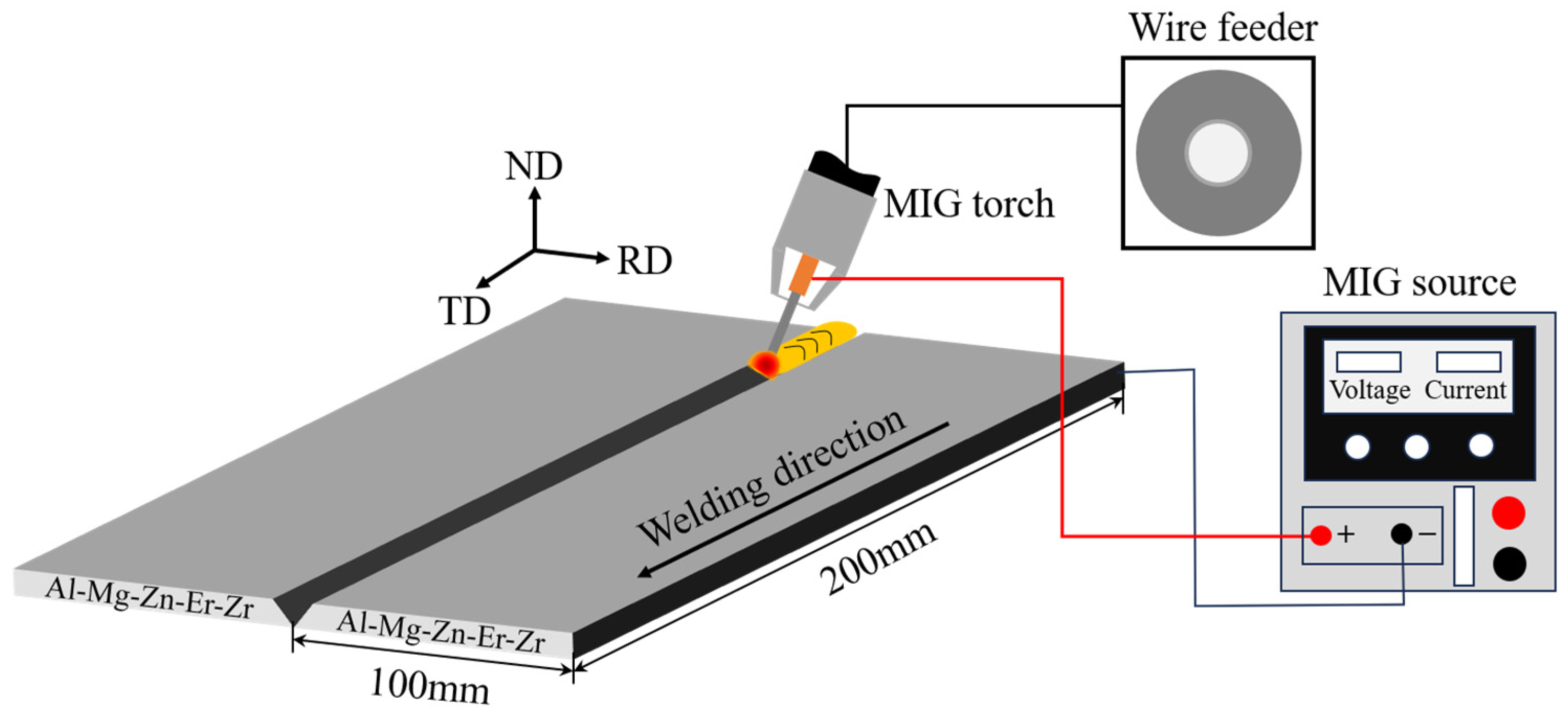
Figure 1. Schematic of multi-pass MIG welding of Al-5.83Mg-0.84Zn-0.17Er-0.12Zr alloys.
Metals 16 00286 g001
Figure 2. (a) Groove design; (b) build-up welding pass design.
Metals 16 00286 g002
Figure 3. (a) Weld appearance of multi-pass MIG-welded joint of Al-5.83Mg-0.84Zn-0.17Er-0.12Zr alloy; (b) underside; (c) the cross-section.
Metals 16 00286 g003
Figure 4. Microstructure of the multi-pass MIG-welded joint of the Al-5.83Mg-0.84Zn-0.17Er-0.12Zr alloys: (a) BM; (b) HAZ; (c) EQZ; (dg) WM; and (h) schematic of observed locations.
Metals 16 00286 g004
Figure 5. BSE photographs of the welded joint: (a) BM; (b) HAZ; (c) WM; and (d) WM magnified.
Metals 16 00286 g005
Figure 6. X-ray diffractometer (XRD) analysis showing crystallographic orientation of the BM, HAZ, and WM of the welded joint.
Metals 16 00286 g006
Figure 7. TEM image of the BM and the WM of the MIG-welded joint. (a) Al6(Mn, Fe) and Al3Mg2 with EDS maps; (b) Al3(Er, Zr) with EDS maps; (c) HRTEM image and corresponding electron-diffraction pattern of Al3(Er, Zr); (d) Al3(Er, Zr) in WM-1; (e) Al3(Er, Zr) in WM-2; (f) Al3(Er, Zr) in the BM.
Metals 16 00286 g007
Figure 8. IPF maps and grain size distributions of the welded joint. (a,b) BM; (c,d) HAZ; (e,f) WM-1; (g,h) WM-2.
Metals 16 00286 g008
Figure 9. KAM maps and GND density distribution of the welded joint. (a,b) BM; (c,d) HAZ; (e,f) WM-1; (g,h) WM-2.
Metals 16 00286 g009
Figure 10. Microhardness map of the welded joint. (a) The cross-section, and (b) along the midline of the cross-section.
Metals 16 00286 g010
Figure 11. Stress–strain curve of the BM and the MIG-welded joint.
Metals 16 00286 g011
Figure 12. Fracture appearance of the welded joint. (a) ductile dimples; (b) quasi-cleavage facet.
Metals 16 00286 g012
Figure 13. Distribution of different crystal types of the MIG-welded joint.
Metals 16 00286 g013
Table 1. The chemical composition of the BM and filler wire (wt.%).
MaterialMgMnZnFeSiErZrAl
BM5.830.700.840.130.060.170.12Bal.
filler wire6.201.060.010.100.200.410.09Bal.
Table 2. EDS position scanning results for the second phase (at.%).
SpectrumMgMnFeZnErZrAlPhases
A5.2113.819.340.23//Bal.Al3Mg2, Al6(Mn, Zn)
B0.7812.6512.470.440.12/Bal.Al6(Mn, Zn)
C5.334.014.10/7.880.03Bal.Al3Mg2, Al6(Mn, Zn), Al3Er
D9.971.741.460.271.95/Bal.Al3Mg2
E9.082.782.50/11.330.05Bal.Al3Mg2, Al3Er
Table 3. Misorientation angle distribution and recrystallized area fraction of the BM, HAZ, and WM (%).
HAGBsLAGBsRecrystallization
BM29.071.010.4
HAZ59.940.159.3
WM-183.316.791.1
WM-287.412.692.9
Table 4. Tensile properties of the BM and the welded joint.
UTS/MPaYS/MPaEI/%Joint Efficiency
BM394 ± 3246 ± 114.0 ± 1.0/
The Joint316 ± 8181 ± 310.5 ± 2.00.80
Single-pass joint [17]337.5/8.50.81
Disclaimer/Publisher’s Note: The statements, opinions and data contained in all publications are solely those of the individual author(s) and contributor(s) and not of MDPI and/or the editor(s). MDPI and/or the editor(s) disclaim responsibility for any injury to people or property resulting from any ideas, methods, instructions or products referred to in the content.