


Abstract
The black streak defect on the surface of 304 stainless steel is one of the key issues affecting the quality of stainless-steel products and the economic benefits of the industry. Cold-rolled plates were selected, and the microscopic images and composition of the sample surface were analyzed using a super-depth optical microscope, SEM, and EDS for the areas without black streaks and black stripe defects. There are significant differences in morphology and composition between areas without black streaks and areas with black streak defects. The mold flux particles will form uneven protrusions and pits on the surface of stainless steel. The height difference between the protrusion and the stainless-steel surface is greater than 20 μm. The black streak defect area on the surface of stainless steel clearly contains elements such as C, O, Si, Na, and Al, which are related to the composition of the mold flux particles. Therefore, the reasons and mechanisms for the formation of black streak defects were analyzed. The root cause of black streak defects is the inclusion of carbonaceous mold flux particles in the molten steel during the continuous casting process. In the continuous casting process and equipment, by adjusting the mold taper, controlling the insertion depth of the submerged entry nozzle, selecting the mold flux suitable for melting characteristics, stabilizing the casting speed, and other measures, the liquid level in the mold during the molten steel casting process was stabilized, and the production conditions were effectively improved for the working condition with a casting speed of 1.45 m/min. The occurrence rate of black streak and degradation rate continued to decrease and were stabilized below 3% and 1%, respectively.
1. Introduction
304 stainless steel is an important type of austenitic stainless steel. It has excellent corrosion resistance, as well as superior mechanical processing performance and good weldability [1,2]. Its applications mainly cover fields such as industrial equipment, architectural decoration, household goods, medical devices, food processing, ships, and nuclear energy [3,4,5,6]. As a special steel, it has relatively high added value, so there are also higher requirements for its internal and surface quality [7,8,9,10,11].
Due to its composition and different solidification characteristics, 304 stainless steel has a wide temperature range for liquidus and solidus. In the actual production process, due to factors such as fluctuations in equipment operation, unreasonable process control, and unstable performance of mold flux, black streak defects may appear on the surface of rolled plates, resulting in a downgrade of product grades. It is known that defects of rolled metal are standardized; the black streaks is one of the standard GOST 21014-88 describes and illustrates 64 types of defects of black (steel) rolled metal. [12] In particular, the long strip-shaped “black streak” defect is a frequent problem on the surface of stainless-steel products and thus has received close attention from industry.
Lu Haifei et al. [10,11] analyzed the black streak defect on the surface of 304 austenitic stainless steel and, in combination with the flow field behavior within the mold, identified the source of the defect as the coiling of slag steel. By controlling the continuous casting process and stabilizing the billet casting speed and other measures, the probability of slag curling has been effectively reduced. They analyzed the morphology and composition of the black streak defects that appeared on the surface of 304 stainless steel hot-rolled coils after annealing and pickling by SEM and EDS. It is believed that the black streak defect is caused by the deformation of the continuous casting mold flux after rolling. Measures such as adjusting the carbon content in the mold flux, reducing the casting speed, and fully grinding the upper and lower surfaces of the slab are proposed, all of which can effectively reduce the occurrence rate of black streak defects. Li Jingyu et al. [13] sampled hot-rolled and cold-rolled plates, observed the surface of line defects, discovered many large-sized carbonaceous particles, and analyzed the causes of line defects. It is proposed that the carbonaceous particles originate from the enrolling of the mold flux of the mold. The carbonaceous particles on the surface of the billet can cause surface line defects of the hot-rolled plate.
Huang Lei [14] et al. studied the black linear defects on the surface of 304 hot-rolled pickled steel coils and believed that their formation was mainly related to carbon-containing substances. The black linear defect is the result of the evolution of carbon-rich impurities trapped under the surface of the billet due to the fluctuation of the liquid level during the continuous casting process after rolling. Ren Lei believes that the severe fluctuation of the liquid level in the mold is an important reason for the formation of curled slag in the cast billet, which affects the quality of the cast billet [15]. Wang Wei et al. [16,17,18,19,20] studied the black streak defects on the upper and lower surfaces of 304 stainless steel cold-rolled coils and believed that during the continuous casting process of stainless steel, when the free carbon content in the mold flux is too high, it causes the melting rate to be too slow, resulting in insufficient replenishment of liquid slag, and the stainless steel billet directly contacts the carbon-rich layer of the mold flux or is drawn into the sintering layer.
The black streak problem produced after the rolling of 304 stainless steel has always been a major constraint on the efficiency and quality improvement of special steel enterprises. Through the unremitting efforts of metallurgical workers, the occurrence rate of black streaks has decreased from 15% ten years ago to less than 3% at present. With the continuous improvement of the technical and equipment levels of domestic stainless steel manufacturing enterprises, higher production efficiency has been achieved. Many enterprises have increased the continuous casting speed from 1.2 m/min to 1.45 m/min, which has led to an increase in the occurrence rate of black streak defects on the surface of 304 stainless steel, reaching over 10% at times. Previous studies have reported measures involving continuous casting control and mold flux composition. However, the coordinated adjustment of casting conditions and mold flux melting behavior remains important when increasing the plant casting speed from 1.2 to 1.45 m/min. The present work addresses this production challenge by combining defect characterization, mold taper and submerged entry nozzle adjustments, and optimization of mold flux properties. Its contribution is the integrated application of these measures to reduce black streak defects under the higher-speed production conditions investigated here.
This thesis takes the surface black streak defect as the research object. The defect is analyzed using an ultra-depth-of-field optical microscope, a scanning electron microscope, and an energy spectrometer, and the types of inclusions and their formation mechanisms are analyzed. By adjusting the composition and performance of the mold flux and improving the continuous casting process, the continuous casting environment in the mold has been effectively improved, production has been stabilized, and the occurrence rate of black streak defects has been reduced to less than 3%. This can provide theoretical and practical references for solving black streak defects on the surface of 304 stainless steel.
2. Sample and Test Characterization
2.1. Selection and Characterization of Black Streak Samples
Select 304 stainless steel cold plates with black streak defects from a domestic factory, and cut them into 15 mm × 15 mm square samples. An ultrasonic cleaning machine is used for sample cleaning. After drying, they were used for subsequent tests.
The original surface of the selected sample was observed using the Kathmatic of China ultra-depth-of-field digital microscope in reflective mode. The surface morphology of the sample was characterized using the Zeiss Ultra Plus field emission scanning electron microscope produced by Zeiss of Germany; the testing conditions are as follows: Pt is sprayed onto the tested surface to enhance its conductivity, and the accelerating voltage is set at 5 KV. Meanwhile, the characteristic X-rays generated by the interaction between electrons and the sample were collected by combining the energy-dispersive spectrometer (EDS), and the elemental composition and content of the sample were determined by analyzing their energy distribution.
2.2. Mold Flux Materials and Their Performance Characterization
Table 1 presents the main chemical compositions of two mold fluxes: M is used for continuous casting at a casting speed of 1.2 m/min, and N is used at 1.45 m/min. For mold flux N, its oxide composition adjustment mainly involves increasing the contents of Li2O, Na2O, and F- (or CaF2), while reducing the content of Al2O3. This adjustment lowers the alkalinity R of the mold flux from 1.15 to 1.12.
Table 1.
Chemical compositions of mold flux (wt%).
The viscosity-temperature curve of the mold flux was determined using the RTW-10 high-temperature rotational viscometer produced by Northeastern University of China. A crucible containing 200 g of decarburization mold flux was placed in a viscosity testing instrument, and the mold flux was heated to 1300 °C and held for 5 min to ensure that the mold flux was completely melted and homogenized. Then, the measuring rod was lowered to a height of 10 mm from the bottom of the crucible. After reaching a constant temperature, start the rotation at a speed of 200 r/min. The cooling rate was set at 3 °C/min to obtain the viscosity-temperature curve.
The prepared mold flux (200 mesh) was added to the mold and pressed into a small cylinder with a diameter of 3 mm and a height of 3 mm. The sample was placed on an Al2O3 ceramic slide and sent into the GX-III high-temperature microscope at a heating rate of 15 °C/min. According to the contour changes of the cylinder, its characteristic temperature is recorded. The melting temperature is the temperature at which the height of the mold flux small cylinder drops to half, which is called the “hemispherical point temperature”. The temperature at which the sample height drops to 25% of the original is defined as the flow temperature.
3. Results and Discussion
3.1. The Black Streak Phenomenon on the Surface of Stainless Steel
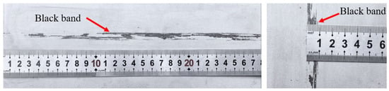
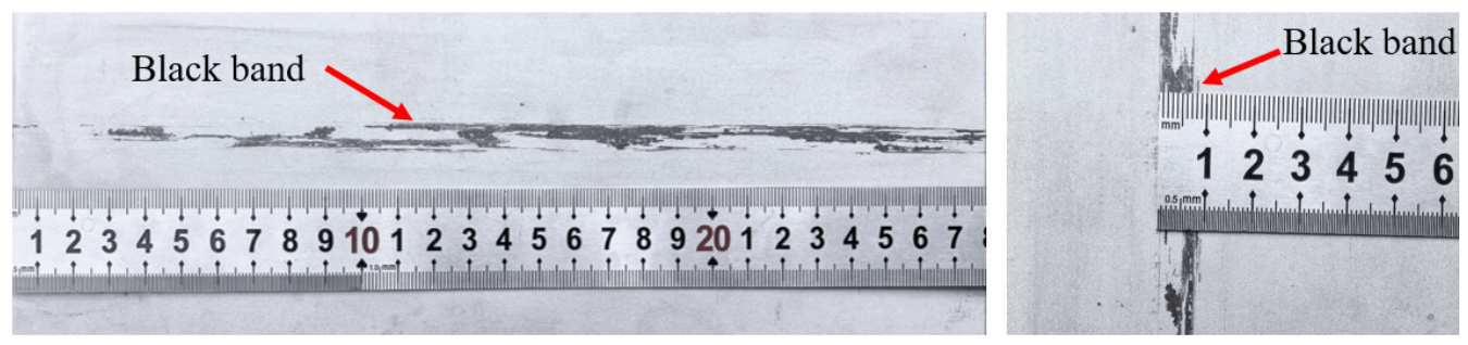
Figure 1 shows a photograph of a 304 stainless steel sheet produced by a specific factory, with black band defects on its surface. These black band defects extend along the rolling direction of the steel strip, appearing as rough long strips with a width of approximately 2.0–8.0 mm and lengths ranging from tens of centimeters to several meters. Their color is uneven, black or grey; the surface is rough and uneven, and a granular texture can be felt by touch.
Figure 1.
Photo of 304 stainless steel.
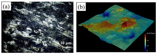
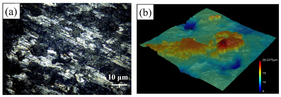
Figure 2 shows the surface of the 304 stainless steel sample under a super depth-of-field digital microscope, where (a) denotes the defect location and (b) denotes the three-dimensional super depth-of-field scanning image. It can be found that the parts of the steel strip with an uneven surface, light color, and metallic luster are the stainless-steel surface. In the area with almost no metallic luster, there are large patches of dark substances resembling rocks, and almost no complete grains can be seen. It can be inferred that the black streak defect may be caused by foreign substances and affect the normal grain structure on the surface of the steel strip.
Figure 2.
Photo of the surface of 304 stainless steel specimen under a super depth digital microscope. (a) defect position; (b) 3D super depth scanning image.
The reason for this phenomenon is directly related to the material properties of the normal position and the defect position. The reason is that the free electrons on the metal surface strongly reflect light waves, making its surface have a very high reflectivity [17], especially presenting a bright metallic luster after polishing. The surface of inorganic non-metals has no free electrons, and light is scattered or absorbed, presenting a dull or mottled color.
A 3D ultra-depth-of-field scan was conducted on the black streak area. The relatively flat green area in the picture represents the surface of stainless steel. The brownish-red area represents the mold flux particles adhering to the surface of the stainless steel and being taller than it. The height difference between the highest point and the plane is already greater than 20 μm. The blue area indicates pits below the surface of the stainless steel, which may be related to the shedding of mold flux particles that have been deposited on the surface of the stainless steel.
3.2. SEM/EDS Analysis of Stainless-Steel Surfaces
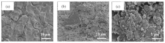
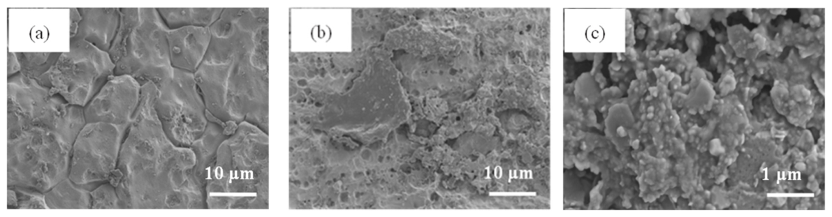
Figure 3 presents the field emission scanning electron microscopy image of the black streak sample, where Figure 3a depicts the normal region, Figure 3b illustrates the defect location, and Figure 3c shows the magnified view of the defect. The ecchymosis at the normal position develops normally, with clear grain boundaries, while at the location of the black streak defect, there is a layer of irregularly shaped substances either covering or mixed on the surface of the steel band.
Figure 3.
Microscopic morphology of lamination defects: (a) normal region; (b) defect position; (c) magnified image of the defect.
Together with the macroscopic observations in Section 3.1, these images provide a multiscale description: Figure 1 shows the longitudinal streak morphology, Figure 2 resolves local surface relief, and Figure 3 compares the normal and defective regions at the 10 μm scale and resolves the deposits at the 1 μm scale. The SEM/EDS observations in Figure 4 and Figure 5 further relate these local features to their elemental composition.
Figure 4.
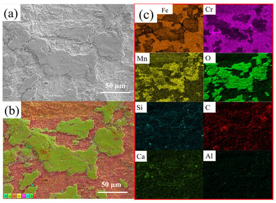
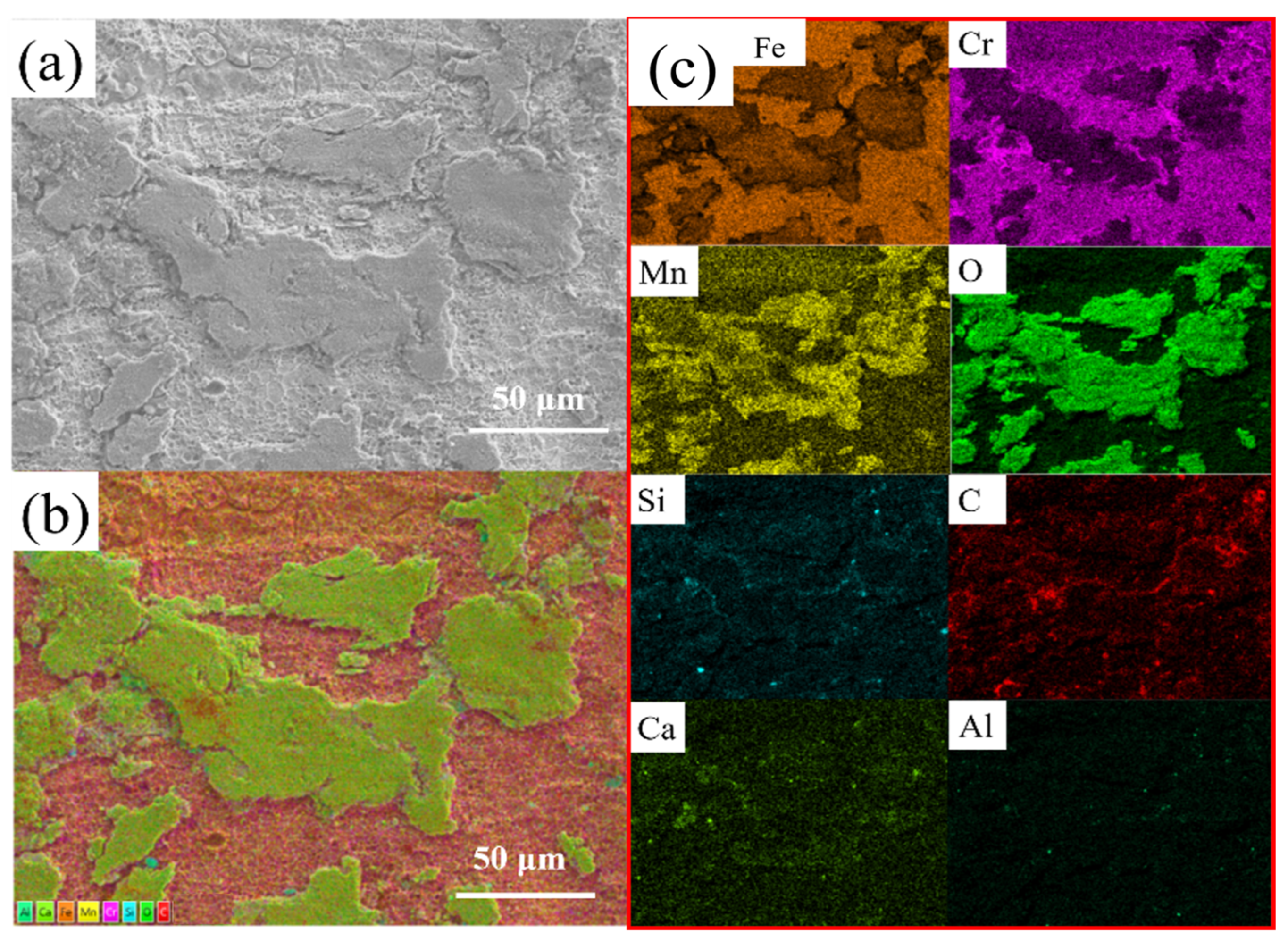
Microscopic morphology and energy spectrum of black streak defect area. (a) Select electronic images; (b) EDS layered images; (c) Distribution image of each element.
Figure 5.
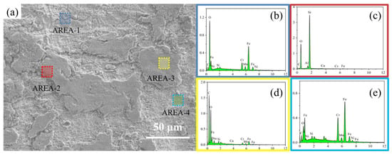
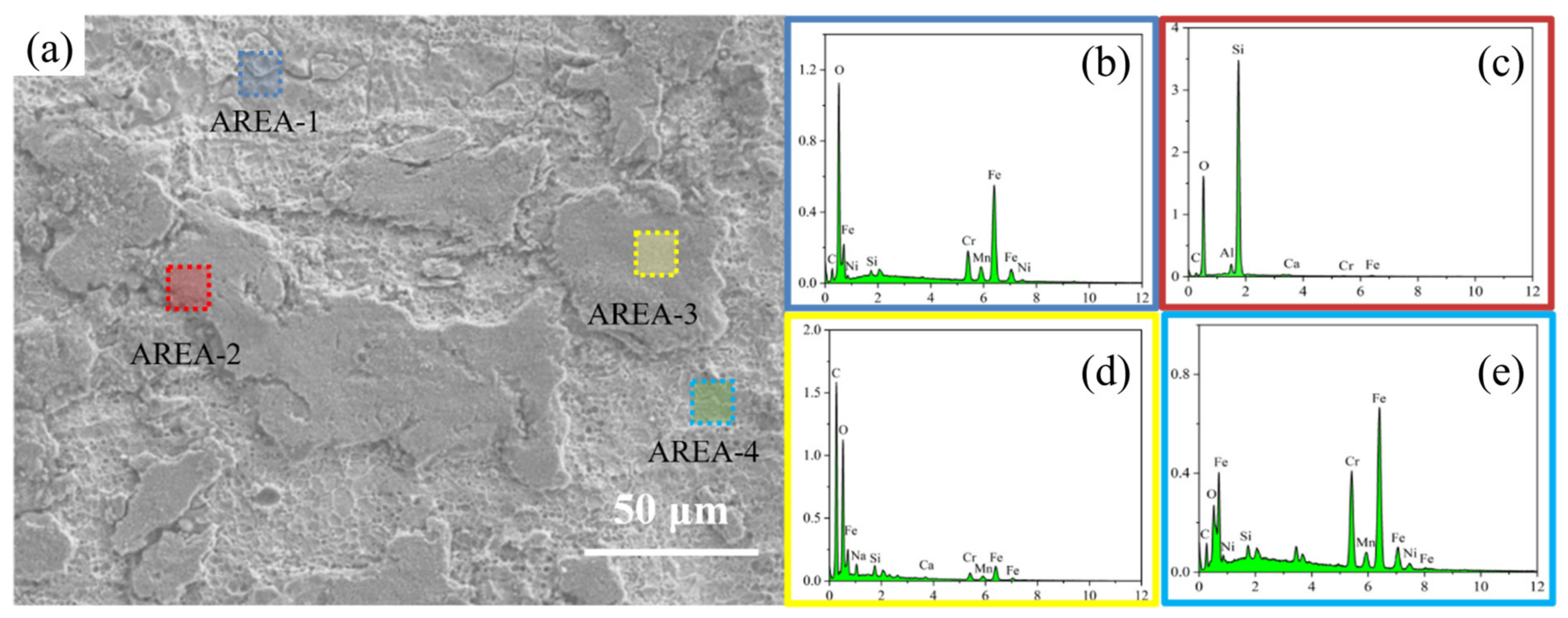
Representative selection area and its small-scale EDS point scan analysis chart. (a) Microscopic morphology of the defect area in the sample; (b) Energy spectra of marked areas (c–e).
Of course, by observing the normal-position SEM image in Figure 3a, it can be found that on the surface of the crystalline grains, there are many small particles of substances attached, which are inseparable from the continuous casting process. In the mold, the surface of the cast billet will encounter a uniform mold flux layer. Under the effect of high temperature and surface tension, the components of the mold flux will adhere to a small amount to the cast billet, resulting in relatively uniform adhesion to the surface of the cast billet. However, for the defect location in Figure 3b, apart from a small amount of adhesion between the billet and the mold flux, the more important reason is that, due to various causes, the billet generates curled slag, which wraps a large amount of mold flux around the surface of the billet, resulting in black streak defects through rolling. In the black streak defect area, almost no complete grain can be seen. Therefore, there are sufficient reasons to infer that the black streak defect may originate from substances other than the billet and affect the normal grain structure on the surface of the steel strip. Figure 3c shows the magnified morphology of the defect area. The defect region is composed of large and small sheet-like and granular substances agglomerated.
To further investigate the chemical composition of black streak defects, the microscopic morphology of the defect surface was selected to obtain electronic images, and EDS analysis was conducted on the chemical composition of the selected area. Figure 4 shows the microscopic morphology and surface scan energy spectrum. Among these, Figure 4a corresponds to the selected electron micrograph, Figure 4b denotes the EDS layered mapping image, and Figure 4c represents the elemental distribution map. As shown in Figure 4a, the surface of the defect is sparsely covered with a layer of irregularly shaped material, and there is a distinct delamination phenomenon between this material layer and the substrate. Figure 4b shows the EDS stratified image. There are significant differences in the elemental distribution between the matrix and the covering material. The electron images mainly include elements such as Fe, Cr, Mn, O, C, Si, Al, and Ca.
To gain a more in-depth analysis of the distribution of chemical components in different regions, representative areas were selected for small-scale EDS spot scanning, as shown in Figure 5. By measuring the energy spectrum of the marked area, the chemical composition of the scanned area can be determined. It can be seen from Figure 5 that there are obvious differences in the point-scan energy spectra of the selected area. Figure 5b shows the stainless-steel substrate at the defect position in AREA-1. The surface is rough and like a honeycomb structure, with the main elements being Fe, Cr, Mn, O, C, and Si. In the same AREA-2, the stainless-steel substrate was selected, as shown in Figure 5c, and the main elements were still Fe, Cr, Mn, O, C, and Si. However, there are certain differences in the signal counts of each element between the two. Figure 5d shows the patch at the defect position in AREA-3. Its surface is significantly higher than that of the stainless-steel substrate. The main elements are Si, O, Al, C, and Ca. It is obvious that it belongs to a non-metallic substance. Figure 5e shows the patch at the defect location in AREA-4, with the main elements being C, O, Fe, Si, and Na, which still belong to non-metallic substances.
Table 2 shows the main components (atomic fractions) of the EDS spot scan in the selected area. It can be seen from Table 2 that the three elements with the highest content from AREA 1 to AREA 4 in the spectra are O, Fe, and C in AREA 1; Fe, C, and Cr in AREA 2; O, Si, and C in AREA 3; and C, O, and Fe in AREA 4. From this, it can be judged that the changes in the chemical composition of the black streak defects caused during the continuous casting process are quite significant.
Table 2.
The main components of EDS in the selected area (Atomic number fraction %).
AREA-1 and AREA-2 differ substantially: their C atomic fractions are 16.91% and 29.05%, their O fractions are 41.20% and 9.68%, and their Cr fractions are 5.80% and 15.07%, respectively. The higher O fraction and lower Fe and Cr fractions in AREA-1 are consistent with a greater contribution from oxygen-containing surface material than in AREA-2. These areas are steel-associated regions within the defect rather than clean bulk-substrate measurements. Their differences reflect heterogeneous surface coverage and the varying contributions of deposits and steel to the normalized EDS composition. The higher C fraction in AREA-2 cannot be explained by oxide coverage alone; carbon-containing surface material or contamination may also contribute.
3.3. The Formation Mechanism of Black Streak Defects
Through the above test analysis and related research [10,12], it can be clearly determined that the black streak defect on the surface of 304 stainless steel belongs to substances other than the iron matrix. The reason for its formation lies in the combined effect of factors such as the continuous casting process control, the structure and flow field of the mold, and the performance of the mold flux during the continuous casting process. The above factors can cause overly intense fluctuations on the surface of the molten steel inside the mold [19,20], leading to overly intense scouring of the mold flux layer. Under the influence of the shear force on the surface of the molten steel, the mold flux droplets are detached from the liquid slag layer and drawn into the area below the interface of the molten steel, resulting in the behavior of the molten steel carrying and mixing the mold flux. The problem of slag entrapment in production is the root cause of black streak defects. The location and quantity of mold flux entrapment determine the morphological characteristics of surface line defects in the plate and coil. Once the slag appears on the surface of the molten steel, point and line defects will form on both hot-rolled and cold-rolled plates, although the formation mechanisms of the two are slightly different.
For hot-rolled plates, before the continuous casting billet is rolled, it needs to be heated to above 1200 °C in a heating furnace. When the mold flux is drawn into the surface of the continuous casting billet, the surface of the billet will be oxidized, forming oxide layers such as Fe2O3 and Cr2O3. The carbonaceous particles trapped in the mold flux on the surface of the continuous casting billet will react with the oxide film layer. The CO gas produced by the reaction will destroy the compactness of the oxide film. The channels and holes formed by the gas escape will cause oxygen to react with the inner steel substrate [21], and form pits and honeycomb-like morphology on the surface of the steel billet. The stainless-steel oxide scale has a strong adhesion to the substrate. The surface carbonaceous particles and inorganic oxides in the mold flux will be firmly connected through M-O bonds, which causes surface defects in hot-rolled plates and brings great difficulties to the subsequent pickling and slag removal.
For cold-rolled plates, when the liquid level in the mold fluctuates greatly and the mold flux is drawn into the interior of the continuous casting billet, line defects may not occur on the surface of the hot-rolled plate during the hot rolling process. After entering the cold rolling process, as the cold rolling proceeds, the slab becomes thinner, and the mold flux that is not visible in the steel matrix gradually approaches the surface of the slab and is exposed. Hard inorganic substances and carbon particles can scratch the surface of cold-rolled steel plates, thus forming obvious black streak line defects.
To sum up, there are mainly three reasons for the formation of black streaks. The first one is that the mold flux liquid remains on the surface of the steel billet, and the carbon fixation particles form defects during rolling. The macroscopic morphology of this defect is manifested as relatively shallow and fine black streaks without scratches. The second is that the mold flux particles are rolled into the molten steel, causing the slag to roll. The macroscopic morphology of this defect is characterized by deep and wide black streaks in the form of scratches. Thirdly, the poor performance in protecting slag particles leads to a well-developed sintering layer, causing the oxide scale to be difficult to remove and forming defects. The macroscopic morphology of this defect is manifested as short, extremely wide, and irregular black streaks in the form of scratches. From the above analysis, the appearance of black streak defects on the surface of stainless steel is caused by a variety of combined factors during the continuous casting process. The relatively intense fluctuations on the surface of the molten steel during the continuous casting process are the inducement of black streak defects, and targeted improvements and adjustments are needed to ensure the stability of the surface of the molten steel.
4. Improvement Measures and Effects
4.1. Taper Adjustment of the Mold
The shrinkage behavior of 304 stainless steel liquid in the continuous casting mold is a dynamic, complex process influenced by multiple factors. The most significant shrinkage that occurs when changing from liquid to solid is the solidification shrinkage of austenitic stainless steel, with a shrinkage rate typically ranging from 3% to 5%, slightly higher than that of carbon steel. While considering the solidification shrinkage, as the casting speed increases from 1.2 m/min to 1.45 m/min, it will lead to a decline in the stability of the continuous casting mold operation, especially the fluctuation at the steel liquid level will be intensified. Therefore, adjustments need to be made in the design of the mold taper.
The conical design of the narrow surface of the mold can effectively compensate for the thermal shrinkage of the solidified shell and reduce the formation of air gaps. For austenitic 304 austenitic stainless steel, its solidification shrinkage ratio is relatively higher, which is prone to cracks and depressions. Appropriate taper adjustment to compensate for the shrinkage of the solidified shell can form sufficient air gaps to facilitate the inflow of liquid mold flux, which is beneficial for controlling heat transfer and lubricating the cast billet. If the taper of the mold is too large, it will increase the wear of the copper plate of the mold, especially the wear at the lower mouth of the mold. While reducing the service life of the equipment, it will induce network cracks on the surface of the cast billet, and in severe cases, transverse cracks may occur. Based on our actual production experience in a domestic enterprise, when the casting speed is increased from 1.2 m/min to 1.45 m/min, by improving the process parameters and increasing the taper of the mold from 1.02% to 1.1%, the thickness of the liquid slag layer near the narrow edge of the mold can be increased, reducing the impact of the steel liquid upwelling on the slag, preventing the entrapment of mold flux, reducing the incidence of black streak, and achieving good metallurgical results.
4.2. Submerged Entry Nozzle Adjustment
In the continuous casting process, molten steel is injected into the mold through an immersion nozzle. Through long-term research and production practice [22,23], the depth at which the nozzle is inserted into the molten steel surface is approximately 150 mm, which is very close to the molten steel surface and the mold flux layer. During the continuous casting process, when the molten steel flows into the mold through the depth adjustment of the submerged entry nozzle immersion was carried out on machine No. 3 of a certain factory, it is directly directed towards the narrow surface by the side hole jet. During this process, the cross-section of the molten steel flow widens, and the flow rate gradually decreases, forming a certain liquid flow field within the mold [23]. The stability of the molten steel flow field directly affects the incidence of black streak defects. The slag layer is formed due to the high-temperature molten steel flow impacting the mold flux, constantly transmitting heat and causing it to melt. If the slag is drawn into the interior of the molten pool, black streak defects closely related to the mold flux will be formed. The occurrence of slag rolling is closely related to the flow behavior of molten steel in the mold [24].
The depth adjustment of the submerged entry nozzle immersion was carried out on machine No. 3 of a certain factory. During the trial production process, the casting speed was stabilized at 1.45 m/min. The shape of the side hole of the immersion submerged entry nozzle was elliptical, and the angle was horizontal. When the immersion depth of the submerged entry nozzle increases from 140 mm to 160 mm, the fluctuation of the steel-slag liquid level at the narrow surface of the mold gradually decreases, and the coverage of the entire slag layer is improved. This is because when the immersion depth of the submerged entry nozzle increases, due to the effect of the potential energy of the upper molten steel liquid level and the resistance of the molten steel liquid flow, the lifting effect of the upward reflux on the liquid surface decreases, the impact on the steel slag interface weakens, and the fluctuation amplitude of the liquid surface decreases accordingly. Similarly, the fluctuation amplitude of the liquid surface at the meniscus will also decrease accordingly, which is conducive to improving the stability of the steel slag interface. The overall evaluation shows that the stability of the steel slag interface is the best when the immersion depth of the submerged entry nozzle on machine No. 3 is 150 mm, and the probability of defects in the cast billet is relatively low.
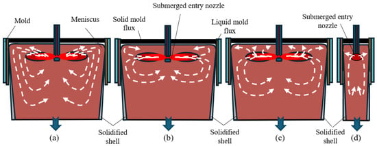
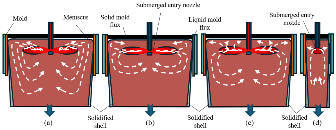
Due to the jet effect of the immersion nozzle, the molten steel will form three regional flow fields in the mold: the jet zone, the upper circulation zone, and the lower circulation zone. The schematic diagram of the liquid flow field pattern in a common mold is shown in Figure 6. Depending on the angle of the side hole of the immersion submerged entry nozzle, the liquid flow field on the wide end face inside the mold may exist in three forms: single circulation flow (a), double circulation flow (b), unstable flow (c), and molten steel flow at the narrow face [25,26].
Figure 6.
Schematic diagram of liquid flow field morphology in crystallizer adapted with permission from Steelmaking. [25]. single circulation flow (a), double circulation flow (b), unstable flow (c), and molten steel flow at the narrow face (d).
There are also different opinions on the inclination angle of the side hole of the submerged entry nozzle [27,28,29,30]. Most studies suggest that a horizontal side hole of the The depth adjustment of the submerged entry nozzle immersion was carried out on machine No. 3 of a certain factory. A downward inclination angle is more conducive to a more stable liquid surface at the submerged entry nozzle, and the meniscus of the mold fluctuates less. Compared with the double circulation flow, the single circulation flow and unstable flow are more prone to defects. This is because the impact depth of the double circulation flow is deeper, which is conducive to weakening the kinetic energy of the steel liquid jet, reducing the liquid surface fluctuation, and reducing the flow velocity on the surface of the mold, thereby suppressing the occurrence of slag curling. Due to the influence of factors such as the size limitation of the mold and the squeezing of the liquid flow, the fluctuation degree of the liquid flow on the narrow end face inside the mold is less than that on the wide end face of the liquid flow field.
4.3. Performance Optimization of Mold Flux
In the continuous casting process of stainless steel, the protective casting method is always adopted [31,32]. The mold flux of the mold mainly serves to insulate, keep warm, absorb inclusions, lubricate, and conduct heat [33]. The mold flux on the surface of the molten steel melts, forming a powder slag layer, a sintered layer, a carbon-rich layer, and a molten slag layer from top to bottom in sequence [34]. Mold flux can also play a unique role in improving the control of black streak defects on the surface of stainless steel. The chemical environment and liquid flow field in the mold will cause some unburned carbon, inorganic mold flux, and the semi-molten layer where solid and liquid coexist to move down together. The carbon in the mold flux here has been isolated from the air and has not been oxidized. This point can be proved by the fact that each test point in Figure 5 contains element C. In response to quality issues such as black streaks on the surface of 304 stainless steel, engineering and technical personnel have conducted some research [33,34], proving that there is a direct correlation between black streaks and mold flux.
During the commissioning process of Machine No. 3 in a certain factory, the casting speed was increased from 1.2 m/min to 1.45 m/min. The liquid level fluctuation in the mold intensified, and it was required that the melting speed of the mold flux be accelerated. Otherwise, if the melting speed is too slow, it will lead to insufficient replenishment of the slag layer in the mold flux and fail to play a good isolation role. The mold flux and carbon-rich layer in the unmelted state of sintering encounter the molten steel and the surface of the cast billet, causing carbon coating or slag entrapment on the surface of the cast billet, and forming black streak defects in the subsequent rolling process.
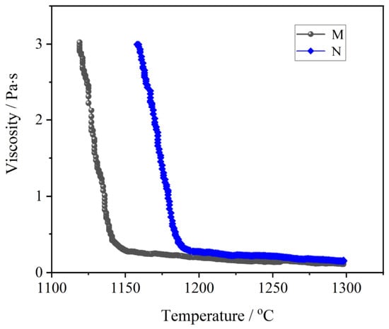
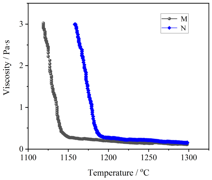
During the debugging process, two types of mold flux (M and N) were designed and used. Figure 7 shows the viscosity and temperature curves of the two types of mold flux, M and N. Both curves show a temperature transition phenomenon, indicating that the structure of the mold flux has undergone significant changes during the cooling process. The reason for this is that crystallization occurred in the mold flux melt during the cooling process. As can be seen from Figure 7, the viscosity of M mold flux at 1300 °C is 0.14 Pa·s, the viscosity at the turning point is 0.41 Pa·s, the temperature at the turning point is 1185 °C, and the viscosity of 3 Pa·s corresponds to a temperature of 1159 °C. The viscosity of N mold flux at 1300 °C is 0.12 Pa·s, and the viscosity at the turning point is 0.42 Pa·s. The turning point temperature is 1141 °C, and the viscosity of 3 Pa·s corresponds to a temperature of 1118 °C. By comparing the turning point temperatures of M and N mold fluxes, the difference between the two is approximately 44 °C, and the melting performance of N mold flux is better. It can also be indicated that the M mold flux will crystallize at a higher temperature during the cooling process, and its crystallization ability is stronger.
Figure 7.
Viscosity and temperature curve of M and N mold flux.
When the continuous casting speed increases, the residence time of the solidified blank shell in the mold is significantly shortened, resulting in a relatively weakened cooling intensity it receives. Under the continuous action of the static pressure of the molten steel, the gap between the copper plate of the mold and the solidified blank shell gradually decreases. This change puts forward higher requirements for the lubrication effect of the mold flux. To ensure that the mold flux can fully penetrate the gaps and form an effective lubricating film, it is necessary to specifically reduce the viscosity of the mold flux and appropriately increase its dosage, thereby avoiding the risk of bonding defects caused by insufficient lubrication of the cast billet. Meanwhile, the structure of the initially solidified shell is relatively weak. If the solid slag film is not adequately lubricated, it is very likely to cause scratches on the surface of the shell. To solve this problem, it is necessary to increase the effective lubrication distance of the solidified shell. Therefore, the alkalinity and turning temperature of the mold flux need to be reduced to lower the crystallization rate, so that the solidified shell can still maintain a good lubrication state in the middle and lower parts of the mold. By increasing the content of sodium oxide and lithium oxide in the chemical composition of the mold flux and reducing its alkalinity, the turning temperature and viscosity can be regulated, and the lubrication performance with the billet shell can be improved. This not only ensures the stability of the high-speed continuous casting process but also significantly enhances the surface quality of the billet.
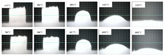
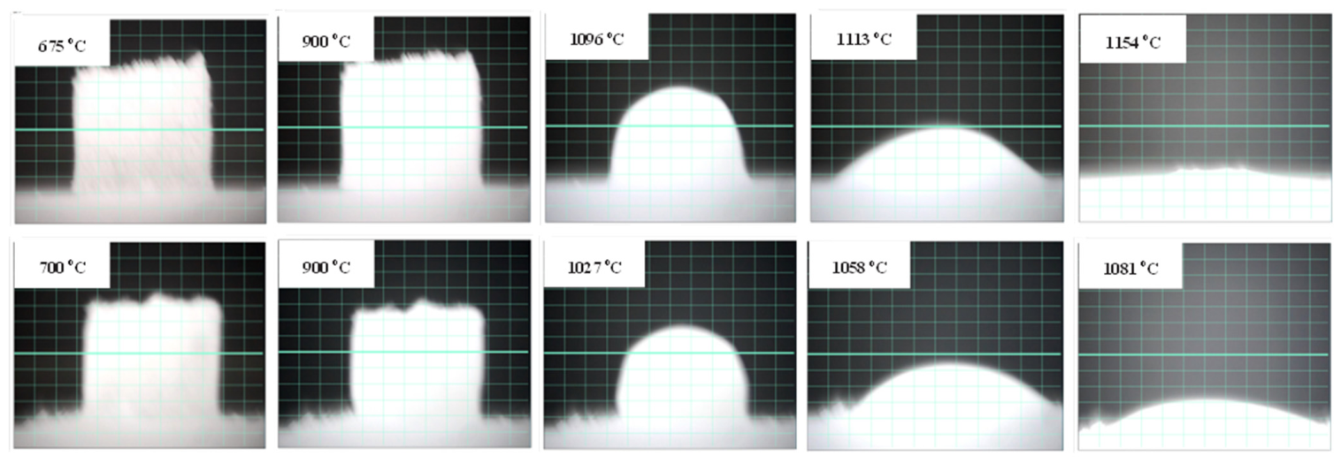
Figure 8 shows the sintering and melting images of two types of mold flux, M and N. There are significant differences in the sintering and melting properties of the two types of mold flux. Table 3 shows the specific heights of cylindrical specimens and the corresponding temperatures.
Figure 8.
Sintering and melting images of M and N mold flux.
Table 3.
Specific heights and corresponding temperatures of cylindrical specimens.
As can be seen from Figure 8 and Table 3, when the temperature reaches the softening temperature, the edges and corners at the upper part of the cylindrical sample disappear, indicating that a large amount of melt is produced. Currently, the surface tension of the melt plays an important role in making the sample approximately hemispherical. As the temperature continues to rise, under the combined effect of gravity and surface tension, the height of the sample gradually decreases from the original cylindrical height to 50% and 25%. At this point, the mold flux has very good fluidity, and the reason for this is consistent with the description of viscosity. The hemispherical temperature and flow temperature of M and N mold fluxes were compared. The characteristic temperature corresponding to N mold flux is approximately 60~70 °C lower, and the melting rate of N mold flux is faster. Accelerating the combustion of carbon and increasing the thickness of the liquid slag layer of the protective slag to isolate the unmelted protective slag and prevent the carbon-containing protective slag from being rolled in, this point can significantly accelerate the melting of the mold flux and is more effective in reducing surface black streak defects when the casting billet casting speed is 1.45 m/min.
4.4. Statistics of the Effects of Industrial Trials
The trial production was carried out on Machine No. 3 of a certain factory. The basic equipment and process parameters were as follows: the cross-sectional size of the cast billet was −1245 × 210 mm, the depth of the spout inserted into the steel liquid surface was approximately 150 mm, the shape of the spout side hole was elliptical, the angle was horizontal (0°), and the casting speed of the continuous casting machine was 1.45 m/min. The mold flux gradually transitioned from M mold flux to N mold flux. The test was conducted in 76 casting batches, using 133 tons of continuous casting mold flux, and lasted for five months.
During the test, relevant parameters were monitored. The continuous casting mold flux had good spreading and flowability in the mold, with a total slag layer of 50–60 mm. The thickness of the liquid slag increased from 11–12 mm when using M mold flux to 16–18 mm when using N mold flux. This change can effectively ensure the melting rate of the mold flux, stabilize the liquid level of the molten steel, isolate the molten steel from the powder slag layer, and achieve the purpose of preventing slag curling. At the same time, stable and uniform slag forms a better lubrication and heat transfer effect between the mold and the cast billet. In addition, the surface of the mold flux at the upper part of the mold is a light blue flame with a moderate height. The average consumption of mold flux is 0.35–0.4 kg/t of steel, ensuring the smooth operation of the process. During the test, no alarm occurred in the mold.
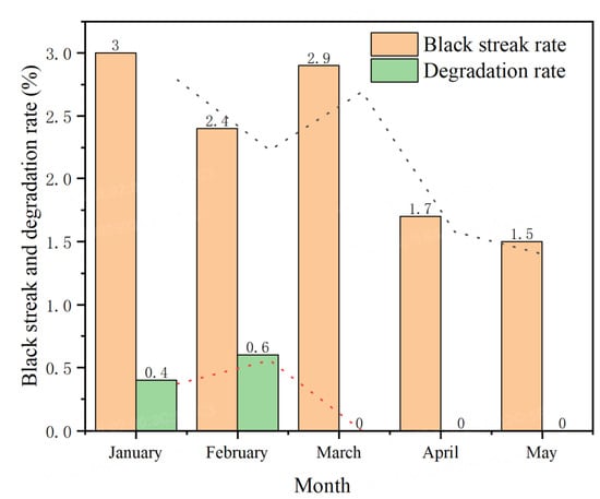
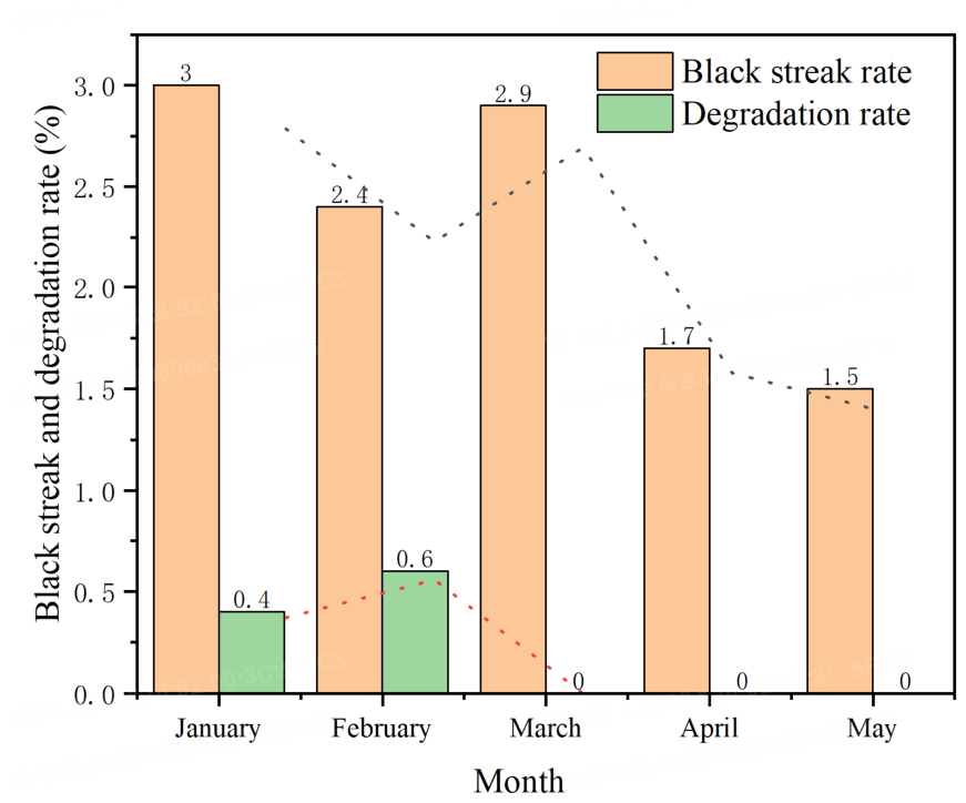
Figure 9 shows the statistics of the occurrence rate and degradation rate of black stripes on the rolling surface of continuous casting billets monthly based on experimental batches after stable production of Unit 3 in a certain factory. The surface of the continuous casting billet no longer has the longer type of black belt as mentioned earlier, and the occurrence rate and degradation rate of black belt remain stable below 3% and 1%, respectively.
Figure 9.
Statistics of the occurrence rate and degradation rate of black stripes on the surface of rolled plates after stable production of Unit 3 in a certain factory.
5. Conclusions
This article conducted a microscopic morphology and composition analysis of the non-black streak area and black streak defect area on the surface of 304 stainless steel samples using a super-depth optical microscope, SEM, and EDS. It was determined that the black streak defect area on the surface of the cold-rolled plate clearly contained elements such as C, O, Si, Na, and Al, which are related to the composition of the mold flux. This proves that the main cause of the formation of the black streak defect is the mold flux.
Through multi-dimensional measures, such as adjusting the mold taper, controlling the insertion depth of the submerged entry nozzle, and selecting mold fluxes suitable for the melting characteristics, the production conditions can be effectively improved. The occurrence rate and degradation rate of black stripes continue to decrease and stabilize below 3% and 1%, respectively. This provides new ideas for reducing the occurrence rate and degradation rate of black stripes in the production process of 304 stainless steel continuous casting at high casting speeds of 1.2–1.45 m/min.
Author Contributions
Conceptualization, C.Z. and X.L.; methodology, X.L., F.H. and C.Z.; software, J.X.; validation, Y.C. and P.X.; formal analysis, X.W., J.Y. and Y.C.; investigation, C.Z. and J.Y.; data curation, C.Z., J.Y. and J.X.; writing—original draft preparation, C.Z. and F.H.; writing—review and editing, C.Z.; visualization, C.Z. and J.Y.; supervision, X.W. and P.X.; project administration, P.X. All authors have read and agreed to the published version of the manuscript.
Funding
This research was funded by from the Young Elite Scientists Sponsorship Program by HAST (2025OEFP017) and the Research Funding Project Supported by the Industrial Joint Fund of Henan Province (251114010003).
Data Availability Statement
The original contributions presented in this study are included in the article. Further inquiries can be directed to the corresponding author.
Conflicts of Interest
Xiaoyang Li, Chunbao Zhao, and Yongyan Chen were employed by the Xixia Longcheng Metallurgical Materials Co., Ltd., Nanyang 474500, China. The remaining authors declare that the research was conducted in the absence of any commercial or financial relationships that could be construed as a potential conflict of interest.
References
- Yang, R.; Wang, P.; Hu, J.; Zhou, H.; Wang, J.; Li, H.; Han, K. Process parameter analysis and microstructural evolution in underwater oscillating laser welded 304 stainless steel. Metals 2026, 16, 1022. [Google Scholar] [CrossRef] [Scilit]
- Tomoyuki, F.; Hikaru, S.; Yoshinobu, S. Stress dependence of electrochemical reactivation and groove development in intergranular corrosion of sensitized type 304 stainless steel. Corros. Sci. 2026, 273, 114320. [Google Scholar] [CrossRef] [Scilit]
- Song, X.; Zhong, X.; Wang, W.; Dou, K. Mitigation of Black Streak Defects in AISI 304 Stainless Steel via Numerical Simulation and Reverse Optimization Algorithm. Materials 2025, 18, 3414. [Google Scholar] [CrossRef] [Scilit] [PubMed]
- Ivanova, T.; Kořenek, M.; Mashlan, M.; Fryšák, M. Investigation of Surface Oxidation of Cast Austenitic 304 Stainless Steel at High Temperatures. Metals 2025, 15, 748. [Google Scholar] [CrossRef] [Scilit]
- Yang, J.K.; Chen, X.Q.; Wang, S.Q.; Jiang, Y.W.; Zhang, T.; Lu, J.Q.; Cui, Y.G.; Ni, M.Y. Microstructural evolution and deuterium permeation resistance of an Al2O3/SiO2/Cr2O3/CaO composite coating on 304 stainless steel under high-temperature permeation conditions. Int. J. Hydrogen Energy 2026, 282, 157789. [Google Scholar] [CrossRef] [Scilit]
- Chen, B.; Ma, X. In-situ investigation on deformation and fracture mechanism of 304/Q235 clad plate produced by hot roll bonding. Vacuum 2025, 233, 113916. [Google Scholar] [CrossRef] [Scilit]
- Li, S.H.; Lan, P.; Lu, Y.F.; An, G.; Shi, Y.; Zhang, L.; Tan, Q.; Jia, H. Inheritance and control of the defect in hot rolled seamless tube by continuously cast billet for austenite stainless steel. Contin. Cast. 2024, 43, 71–79. [Google Scholar] [CrossRef]
- Malandruccolo, A. An Introduction to Stainless Steels. In Superaustenitic Stainless Steels; Engineering Materials; Springer: Cham, Switzerland, 2024. [Google Scholar] [CrossRef] [Scilit]
- Xu, J.L.; Lu, H.F.; Tian, W.G.; Jiang, F.L. Improvement practice of line scale defect of 304 stainless steel cold rolled plate. Steelmaking 2020, 36, 70–77. Available online: http://www.bwjournal.com/lg/CN/Y2020/V36/I2/70 (accessed on 21 October 2026).
- Lu, H.F.; Jiang, F.L.; Xu, J.L. Analysis of black strip defect of 304 stainless steel hot rolled strip. Contin. Cast. 2019, 44, 55–60. [Google Scholar]
- Shan, Q.L.; Jia, L.B.; Peng, G.Z.; Zhang, B.-L.; Liang, Y.; An, Z.-Q. Research of slag defects in hot-rolled plate of ultra-low carbon steel. Contin. Cast. 2016, 41, 54–58. [Google Scholar]
- Konovalenko, I.; Maruschak, P.; Brezinová, J. Steel surface defect classification using deep residual neural network. Metals 2020, 10, 846. [Google Scholar] [CrossRef] [Scilit]
- Li, J.Y.; Cheng, G.G.; Qian, G.Y.; Li, L.; Hu, B.; Wang, G. Line defect on surface of hot(cold)-rolled 304 stainless steel sheets. China Metall. 2017, 27, 29–35. [Google Scholar] [CrossRef]
- Huang, L. Analysis of black linear defects on 304 stainless steel surfaces. Introd. Technol. Innov. 2017, 16, 71–72. [Google Scholar]
- Ren, L.; Zhang, L.F.; Wang, Q.Q.; Zhao, X. Study on fluid flow in a continuous casting slab mold using particle image velocimetry. Chin. J. Eng. 2016, 38, 13931403. [Google Scholar] [CrossRef]
- Wang, W.; Zhang, Z.; Zhang, L.P.; Duan, C.; Shang, G.; Zhang, J. Characteristics and formation mechanism of surface peeling defects on rolled plates of a nickel—Saving austenitic stainless steel. China Metall. 2022, 32, 139–148. [Google Scholar] [CrossRef]
- Ma, Q.Q.; Wu, C.C.; Cheng, G.G.; Li, F.W. Characteristic and formation mechanism of inclusions in 2205 duplex stainless steel containing rare earth elements. Mater. Today Proc. 2015, 2, S300–S305. [Google Scholar] [CrossRef] [Scilit]
- Jiang, C.H.; Tang, D.; Zhang, C.; Zhang, Y.; Zhao, A.M. Morphology and metallurgical factors of line defects on surface of cold rolled 304 austenitic stainless steel. Mater. Res. Innov. 2014, 18, 281–289. [Google Scholar] [CrossRef] [Scilit]
- Wu, Y.D.; Liu, Z.Q.; Quan, M.J.; Li, B. Experimental study on the mechanism of slag entrainment at the slag/metal interface in continuous casting. J. Mater. Metall. 2020, 19, 13–19+64. [Google Scholar] [CrossRef]
- Jin, Y.L.; Bao, Y.P.; Liu, J.H.; An, H. Simulation on steel/slag interfacial behavior and analysis of slag entrapment in a stainless-steel slab continuous casting mold. J. Univ. Sci. Technol. Beijing 2009, 31, 618–624. [Google Scholar] [CrossRef]
- Singh, D.; Cemin, F. High-temperature oxidation behaviour of nanostructure surface layered austenitic stainless steel. Appl. Surf. Sci. 2022, 581, 152437. [Google Scholar] [CrossRef] [Scilit]
- Miranda, R.; Barron, M.A.; Barreto, J.; Hoyos, L.; Gonzalez, J. Experimental and numerical analysis of the free surface in a water model of a slab continuous casting mold. ISIJ Int. 2005, 45, 1626–1635. [Google Scholar] [CrossRef] [Scilit]
- Lei, L.L.; Chang, Y.H.; Luo, Y.Z.; Ji, C.X.; Zhu, J.L.; Xiao, H.; Zhang, J.Q. Submerged entry nozzle and its effect on mold flow behavior of slab casting. Contin. Cast. 2023, 48, 1–16+40. [Google Scholar] [CrossRef]
- Ning, Z.; Hong, L.; Cheng-Jun, L. Physical Model Research on Slag Entrapment and Surface Disturbance in the Continuous Casting Mold. Contin. Cast. 2010, 34, 30. [Google Scholar]
- Zhao, Y.H.; Yang, J.; Zhang, T.S. Latest progress in physical simulation of flow field, slag entrapment, and unsteady processes in slab continuous casting mold. Steelmaking 2025, 41, 1. [Google Scholar]
- Dauby, P.H.; Assar, M.B.; Lawson, G.D. PIV and MFC measurements in a continuous caster mold. New tools to penetrate the black caster box. Rev. Métallurgie 2001, 98, 353–366. [Google Scholar] [CrossRef] [Scilit]
- Kumar, M.; Mishra, P.; Roy, A.K. Analysis of different mould section sizes to optimize the submerged entry nozzle to measure the meniscus fluctuation in a continuous casting mould. Crystals 2021, 11, 564. [Google Scholar] [CrossRef] [Scilit]
- Liu, Y.B.; Tang, H.Y.; Wang, K.M.; Ma, Y.; Shang, G.; Zhang, L.; Zhang, J. Effect of submerged entry nozzle structures on liquid surface flow behavior of slab continuous casting mold. Contin. Cast. 2022, 47, 1–10+17. [Google Scholar] [CrossRef]
- He, Y.; He, M. Analysis of lubrication and heat transfer function of mold flux. Contin. Cast. 2021, 40, 2–6. [Google Scholar] [CrossRef]
- Han, X.; Yan, X.; Liu, L.; Zhao, K.; Wang, C.; Du, L. Research shows progress on heat transfer characteristics of mold flux film in continuous casting mold. Spec. Steel 2021, 42, 6–13. [Google Scholar]
- Zhao, C.B.; He, F.; Li, X.Y.; Chen, Y.; Xie, J. Preparation of hollow particle mold flux for continuous casting by spray drying. China Metall. 2024, 34, 110–117. [Google Scholar] [CrossRef]
- Wang, W.X.; Wang, Y.; Chi, J.H. Surface defects on stain less steel billet and selection of mold flux properties. Contin. Cast. 2006, 30, 28–31. [Google Scholar]
- Ma, J.; Chen, X. Improvement practice for the line scales on surface of 304 stainless steel 2B plate. China Metall. 2015, 25, 54–58. [Google Scholar] [CrossRef]
- Zhao, C.B.; Li, X.Y.; Xu, J.Y.; Chen, Y.Y.; Wang, Y. Improvement of surface cracks and inclusions defect in low carbon steel. Steelmaking 2018, 34, 69–73. Available online: http://www.bwjournal.com/lg/CN/abstract/abstract7134.shtml (accessed on 21 October 2026).

Disclaimer/Publisher’s Note: The statements, opinions and data contained in all publications are solely those of the individual author(s) and contributor(s) and not of MDPI and/or the editor(s). MDPI and/or the editor(s) disclaim responsibility for any injury to people or property resulting from any ideas, methods, instructions or products referred to in the content. |
© 2026 by the authors. Licensee MDPI, Basel, Switzerland. This article is an open access article distributed under the terms and conditions of the Creative Commons Attribution (CC BY) license.