


Abstract
Ironing is an effective process for precisely finishing a formed product at the final stage of a series of forming processes. Generally, a high-performance lubricant oil with high viscosity is used to prevent galling under severe forming conditions, but high-viscosity oil is difficult to remove from the workpiece after the forming process. Residual oil can interfere with subsequent processes such as welding, heat treatment, and painting. Therefore, low-viscosity oils with excellent cleanability are desirable under severe ironing conditions. In this study, differential lubrication was applied to ironing to enable the use of low-viscosity lubricant oil. The results showed that severe galling occurred on the inner surface of the workpiece when a low-viscosity oil was used. However, no galling was observed when low- and high-viscosity oils were applied to the inner and outer surfaces of the workpiece, respectively. These results indicate that differential lubrication enables the use of a low-viscosity lubricant oil without galling while maintaining high surface quality.
1. Introduction
The growing electrification of automobiles has required each component, except for batteries, to be smaller and lighter, because batteries are indispensable components for electric vehicles but are large and heavy. Furthermore, wasted space, including excessive clearance between parts, increases the total size of the component after assembly. Each part is eventually required to achieve higher dimensional accuracy and smoother surfaces. Therefore, ironing is used as a finishing process to manufacture precise and smooth parts.
To utilize the friction force between the tool and the workpiece in bulk forming, Kunogi and Nakamura et al. proposed backward extrusion methods that utilize the frictional force between the die and the workpiece. Reductions in forming force or improvements in the dimensional accuracy of the products were reportedly achieved using these methods [1,2]. However, this research has been limited to extrusion forming. On the other hand, in sheet metal forming, improvement in forming performance has been investigated under different lubrication conditions. Kasuga et al., Atala, and Hassan et al. investigated the improvements in deep-drawing performance using different lubricants between the tools and the workpiece during the deep-drawing process [3,4,5,6,7]. However, this research has been limited to deep drawing. Another line of research has focused on improving surface quality through optimization of forming conditions, lubrication, and numerical simulations. I. Celik et al. reported optimizing forming conditions to improve forming quality in the deep-drawing process of DD13 sheet metal [8]. A. Matras reported an improvement in the quality of polylactic acid by optimizing forming conditions for the material extrusion (MEX), 3D printing, and ironing [9]. X. Zuo et al. reported an improvement in the forming quality of aluminum foil and a reduction in wrinkling during the winding process by optimizing the forming conditions [10]. Abe et al. investigated whether the TiCN-based cermet die with fine lubricant pockets was effective in preventing seizure during the ironing of stainless steel cups using a mineral oil lubricant with a chlorine additive [11]. The effects of the die material, the diameter and material of the particles on the ironing limit were also estimated using lubricants containing nanoparticles [12]. CJ. Tan investigated the effects of the concentration of micro-particles and viscosity of the base oil on the ironing limit of an aluminum alloy cup using lubricants with SiO2 nanoparticles [13]. Wang et al. simulated surface smoothing in the ironing process using FEM, considering the elastic-plastic deformation of the workpiece [14]. Stone et al. investigated the influence of the surface finish and the micro-geometries under different ironing conditions after forging. Additionally, environmentally friendly lubricant oil has also been required in metal forming [15]. Takaki et al. evaluated the anti-galling property of sulfurized olefins with overbased calcium sulfonates on stainless steel to develop a high-performance chloride-free oil [16]. Kawai et al. investigated a surface flattening mechanism during the ironing of an aluminum cup to manufacture a mirror-surfaced cup [17]. Wu et al. investigated the prediction of the effect of surface roughing based on the material data of the sheet metal in its as-received state. They also investigated the friction behavior after pre-straining in strip drawing tests [18]. Trzepieciñski et al. investigated changes in the surface roughness of DC03 steel sheets using strip drawing tests under forced oil pressure lubrication [19]. Although differential lubrication has been investigated mainly for deep drawing, its application to the ironing process has not yet been reported. Furthermore, previous studies often required complicated friction control mechanisms. Therefore, the applicability of a simple lubrication strategy using lubricants with different viscosities remains unclear. In ironing as the final forming process, the following three requirements must be satisfied:
- (1)
- Improvement of product quality with high dimensional accuracy and small surface roughness;
- (2)
- Reduction in the forming load;
- (3)
- Easy removal of the residual lubricant to enable subsequent processes to proceed smoothly (e.g., welding, heat treatment, painting, and plating).
Some solutions for these needs contribute to high productivity as well as environmental sustainability. In the ironing process, a high-performance lubricant oil with high viscosity has been used to prevent galling and reduce the excessive forming load because a thick and tough lubricant film is formed between the tool and the workpiece. The thick lubricant film, however, tends to roughen the product surface due to a free-surface roughening effect. Conversely, the thin lubricant film often breaks down before galling occurs, and the forming load increases. Tool wear is accelerated if high friction is maintained between the tool and the workpiece during a continuous forming process. Thus, conditions for applying a lower-viscosity oil for lubrication during ironing were investigated.
This study aims to expand the applicability of low-viscosity lubricant oil with good removability under severe conditions. A suitable condition was found under which galling was prevented, and the ironing load was reduced, even when a low-viscosity lubricant oil was applied to the surface to be ironed under differential lubrication.
2. Effect of Different Lubricated Conditions for Ironing Using Ball Penetration Operation
2.1. Experimental Method and Conditions
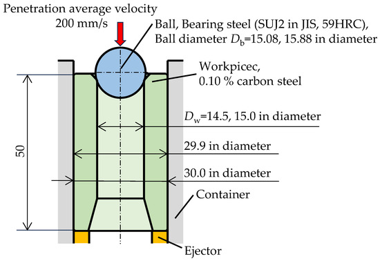
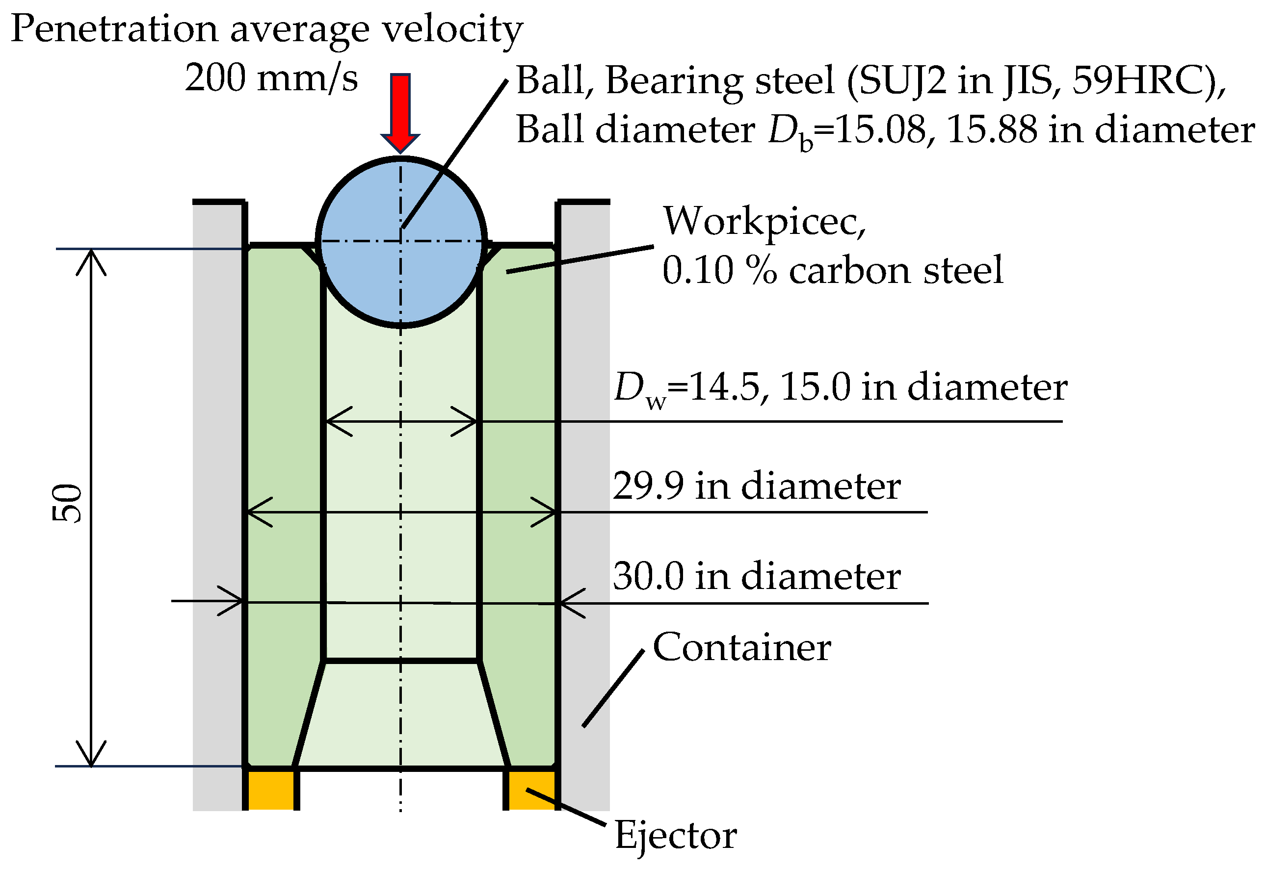
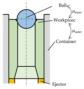
Figure 1 schematically illustrates a ball penetration operation [20]. A ball made of high-carbon and high-chromium bearing steel, SUJ2 in JIS, was used as a tool in this experiment. The ball was pushed into the hollow workpiece using a hydraulic press with a specially designated N2 gas accumulator. The average penetration speed was approximately 200 mm/s, which was calculated from the measured stroke-time data. The ball was hard, precisely the same size as the workpiece, had an extremely smooth surface, and had diameters Db of 15.08 and 15.88 mm. The workpiece was made of 0.10% carbon steel. It had an outer diameter of 29.9 mm and a height of 50.0 mm. The container had a hole with a diameter of 30.0 mm.
Figure 1.
Outline of ball penetration operation.
Table 1 shows the combination of the ball diameter and the initial hole diameter of the workpiece. A Coulomb friction coefficient was used in a friction model between the ball and the workpiece and between the container and the workpiece. Initial hole diameters Dw of 14.5 and 15.0 mm were used. The reduction in cross-sectional area Re is 0.36, 2.5%, 4.0, and 6.0%. where Re = (π/4) (Db2 − Dw2)/(π/4) (302 − Dw2), Db is the ball diameter, and Dw is the initial hole diameter of the workpiece. Re is defined as the ratio of the reduction in the workpiece’s cross-sectional area to the initial cross-sectional area.
Table 1.
Combination of ball diameter and initial hole diameter of workpiece.
Table 2 shows the lubrication conditions in the ball penetration operation. The lubricant oil, VG2, is a pure mineral oil with a low viscosity of 2 mm2/s. Beef fat is a viscous lubricant with a large amount of fatty acids, providing high lubricity. According to preliminary results obtained from ring compression tests using 0.10% carbon steel at a compression speed of 0.1 mm/s and a reduction in height of 35–40%, Coulomb friction coefficients μ of 0.05, 0.08, and 0.11 were measured between the workpiece and the dies under lubricating conditions with beef fat, VG2, and no lubrication, respectively.
Table 2.
Lubrication conditions.
2.2. FEM Analysis Conditions
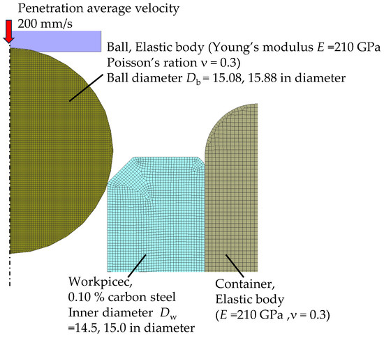
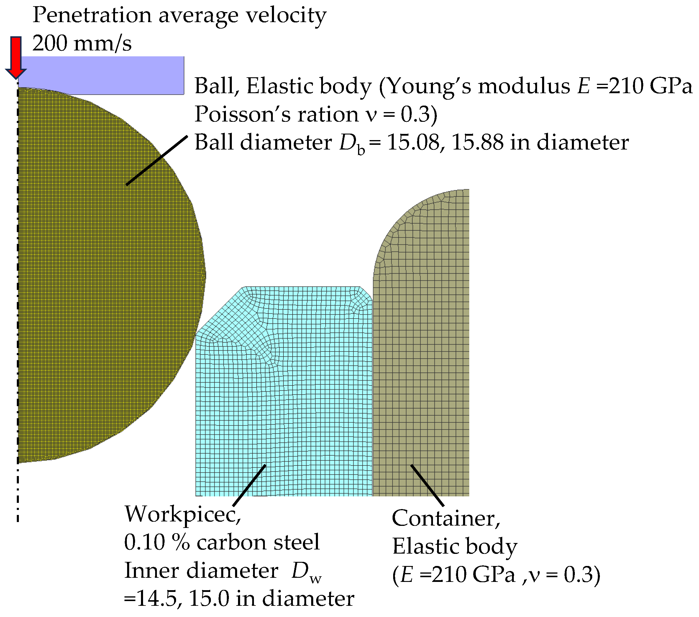
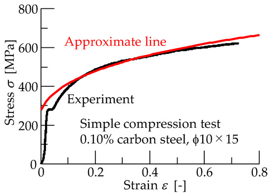
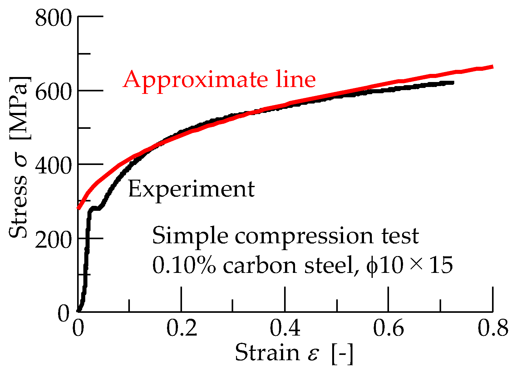
Figure 2 shows the FEM analysis conditions of the ball penetration operation. The ironing load and the plastic deformation of the workpiece were analyzed using a two-dimensional finite element method with commercial code ®simufact.forming 2023. The ball and the container were modeled as elastic bodies, and the workpiece was modeled as an elastic–plastic body. Figure 3 shows the strain–stress curve obtained from a simple compression test at the strain ratio of 0.007 from 0.013.
Figure 2.
FEM analysis conditions of ball penetration method.
Figure 3.
Strain-stress curve of 0.10% carbon steel by a simple compression test.
2.3. Frictional Conditions Between Tools and Workpiece for FEM Analysis
A numerical FEM analysis investigated how the different frictional conditions affected the load and the deformation of the workpiece to interpret the experimental results. The analysis was carried out under the following frictional assumptions:
- (1)
- The setting frictional coefficient remained constant during the calculation.
- (2)
- A Coulomb friction coefficient μ of 0.10 represented poor lubrication, because the Coulomb friction coefficients were 0.11 and 0.08, as determined by the ring compression test under no lubrication and with VG2, respectively.
- (3)
- Under excellent lubrication conditions, a μ value of 0.01 was selected. This lubrication condition includes hydrodynamic lubrication. Under well-lubricated conditions, a μ value of 0.05 was also selected. According to the ring compression test, a μ value of 0.05 was measured when beef fat was used. In cold forging, a zinc phosphate coating combined with soap or a soap–phosphate coating has been widely used, providing well-lubricated conditions. Various tribological tests for metal forming, including extrusion and ring compression, reported μ values ranging from 0.02 to 0.08 [21]. The tests were conducted at room temperature and 200 °C, assuming an increase in temperature during cold forging with large plastic deformation and friction between the tool and the workpiece. The friction decreases with increasing testing temperature because the soap is softened and melted at about 200–300 °C. The effect of frictional conditions between the ball and the workpiece and between the container and the workpiece on the deformation of the workpiece was analyzed by FEM. The frictional conditions for FEM analysis are shown in Table 3. Both (A) and (B) include the following frictional conditions:Table 3. Frictional conditions for FEM-analysis.
(A): the combinations of various μinner = 0.01–0.10 and specific μouter = 0.10
(B): the combinations of specific μinner = 0.10 and various μouter = 0.01–0.10
3. Experimental and Numerical Results of the Ball Penetration Operation Under Differential Lubrication
3.1. Estimation of Galling Prevention Property of Lubricants in the Ball Penetration Operation
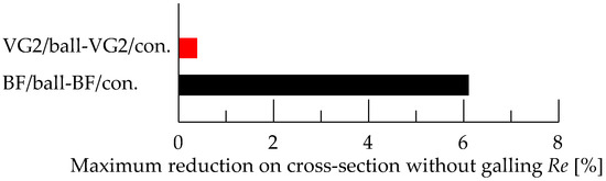
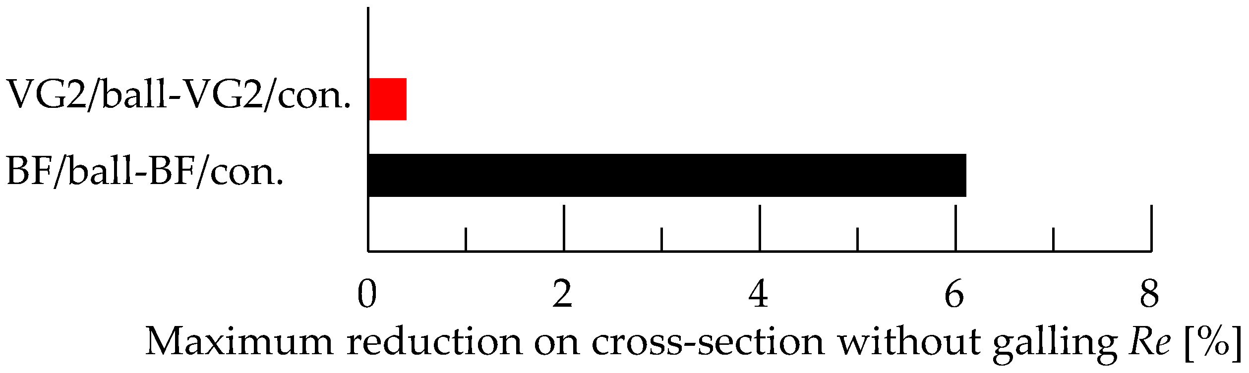
Each workpiece was observed after the ball penetration operation. Galling was found on the inner surface of the workpiece at high Re when the workpiece or the tools were lubricated with the same lubricant, as in normal lubrication in the general ironing process. Figure 4 shows the maximum reduction in cross-sectional area without galling, max Re. Beef fat showed a max Re of 6%, and VG2 showed a max Re of 0.36%. Considering the removability of the residual oil after ironing, a low-viscosity oil, such as VG2, is easy to remove, but it shows poor performance, as shown in Figure 4.
Figure 4.
Estimation of the anti-galling property in hard ironing by ball penetration operation.
3.2. Observation of Typical Inner Surface of Workpiece After Ball Penetration
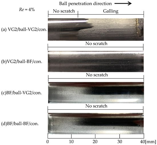
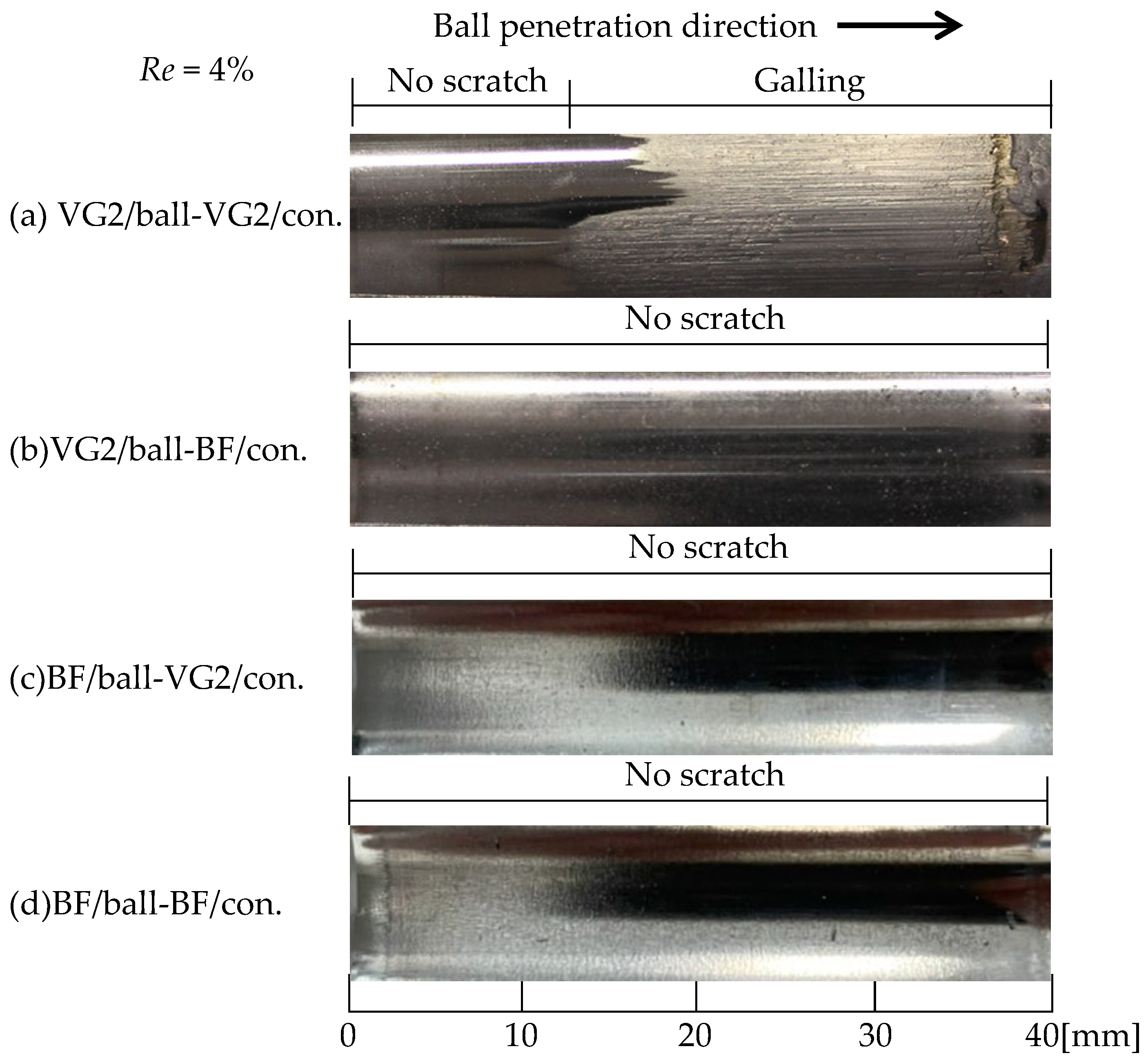
Differential lubrication was used for the ball penetration operation. Figure 5 shows the observation of the typical inner surface of the workpiece after the ball penetration. Severe galling occurred on the inner surface of the workpiece at a stroke of nearly 13 mm under condition (a). It was estimated that the low-viscosity VG2 lubricant could not maintain the necessary thickness of the oil film between the ball and the workpiece even at an early stroke. However, under conditions (b), (c), and (d), no galling was observed on the inner surface of the workpiece, and the forming load was neither high nor unstable. Although each ball was lubricated with VG2 under conditions (a) and (b), a better inner surface was obtained when at least the container was lubricated with the high-performance lubricant, beef fat. However, a smooth and fine surface without galling was observed on the outer surface of the workpiece under conditions (a)–(d). The ball was more difficult to lubricate than the container, because the ball was used for ironing, and the container was used to constrain the outer diameter of the workpiece. Unexpectedly, it was found that lubricating the container was important for achieving the desired ironing.
Figure 5.
Observation of typical inner surface of workpiece after experiment at Re of 4.0%.
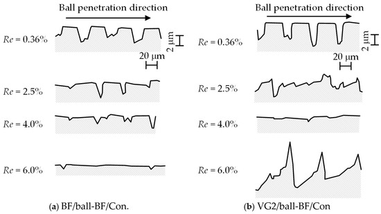
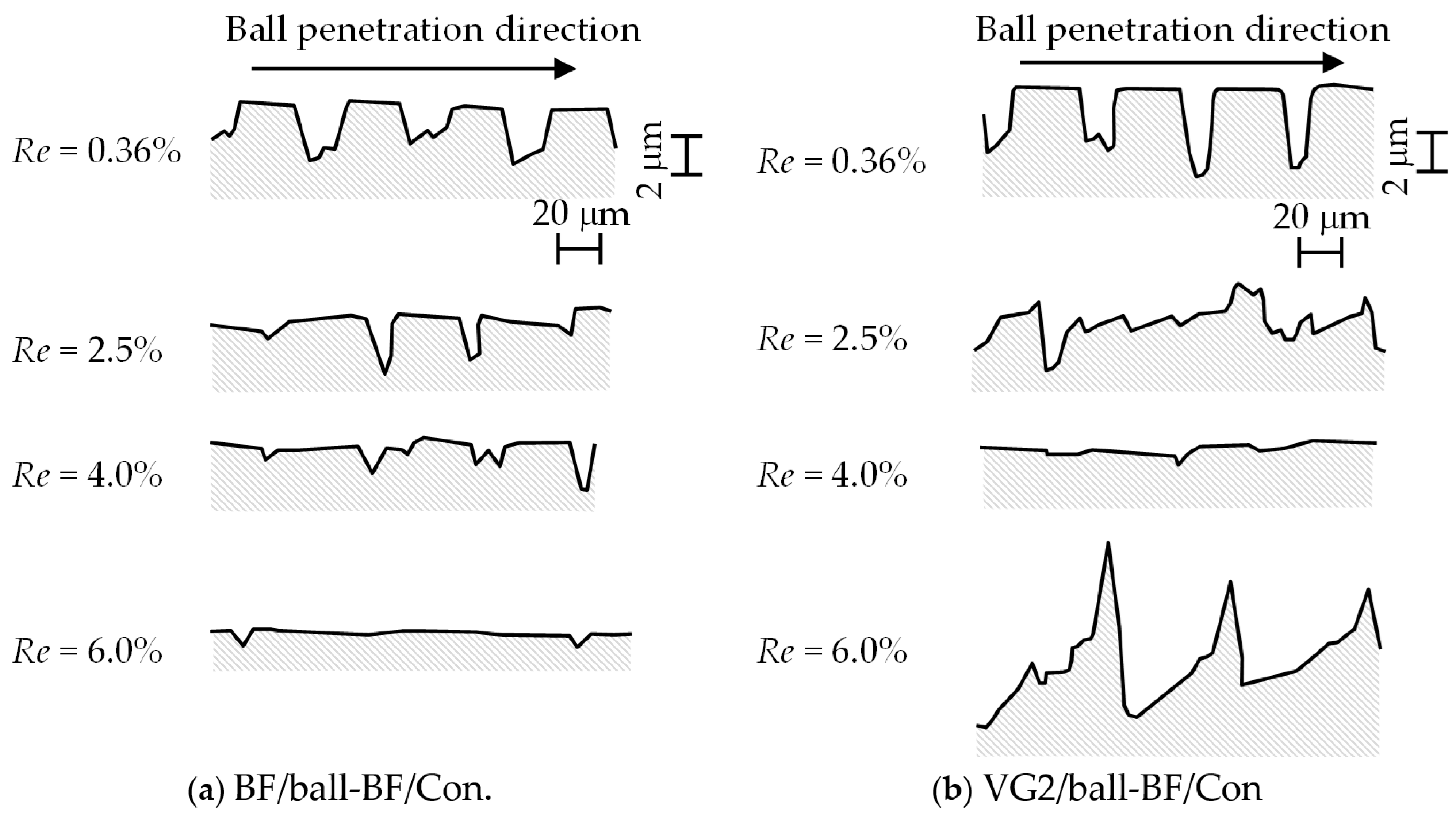
Figure 6 shows the surface roughness profiles measured on the inner surface of the workpiece at a position 30 mm from the entrance after the experiment. These profiles were measured parallel to the penetration direction. The initial roughness of the inner surface was approximately 7.6 μ mRz before the experiment. Figure 6a shows the surface profiles when beef fat was applied to the inner and outer surfaces of the workpiece. The flattened area increases with increasing reduction in cross-sectional area. In this experiment, the forming conditions become more severe as the reduction in cross-sectional area increases. The surface material flow is restricted by the tool under poor lubricant conditions. Consequently, the flattened area on the inner surface increases as the lubricant film becomes thinner. Figure 6b shows the surface profiles when VG2 was applied to the inner surface of the workpiece and beef fat was applied to the outer surface of the workpiece. Adhesion was observed at reductions in cross-sectional area of 2.5% and 6%. At a reduction in cross-sectional area of 2.5%, the lubricant film probably broke down during the experiment. A smaller amount of the lubricant was probably applied than under the other test conditions. A flattened area was observed on the surface at a reduction in cross-sectional area of 4%. A thin lubricant film was maintained between the tool and the workpiece during the experiment.
Figure 6.
Inner surface profile of workpiece at a position 30 mm from entrance after the experiment.
3.3. Typical Ball Penetration Load
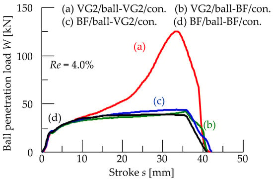
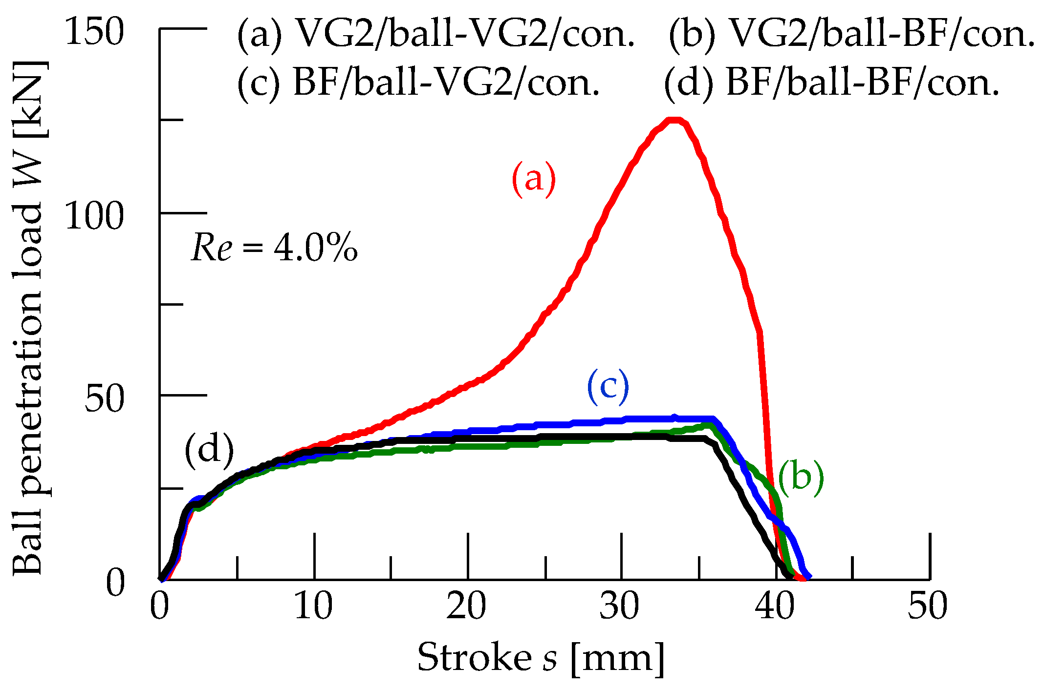
Figure 7 shows typical load–stroke curves during ball penetration when Re = 4.0%. A low and stable load could not be maintained before reaching the highest value of 125 kN under the lubrication condition of (a) VG2/ball-VG2/con., as shown in Table 2. The maximum loads were 125, 44, 42, and 38 kN under the lubrication conditions of (a) VG2/ball-VG2/con., (c) BF/ball-VG2/con., (b) VG2/ball-BF/con., and (d) BF/ball-BF/con., respectively. There were no large differences in loads under conditions (c), (b), and (d), and no galling occurred under these conditions. The most stable load among all the conditions was observed under the well-lubricated condition of (d), where beef fat (BF) containing a large amount of fatty acids was used. Applying BF to both the ball and the container was most effective for lubrication here. However, the viscous BF was difficult to remove from the inner side of the hollow product. The low-viscosity VG2 was easier to remove than the viscous BF, but it was insufficient for lubrication in severe ironing. The previous example under condition (a) clearly showed that VG2 is not a high-performance lubricant oil. Thus, the combination of VG2 and BF was a compromise. The adoption of condition (c) BF/ball-VG2/con. was reasonable because the ball was subjected to higher pressure than the container. Unexpectedly, under condition (b) VG2/ball-BF/con., the load was also low and stable. It is an industrial advantage that the low-viscosity VG2 oil is easy to clean even from the inner side of the product, because the residual oil often causes trouble in subsequent processes such as welding, heat treatment, painting, and plating, etc.
Figure 7.
Typical ball penetration load curves at Re of 4.0%.
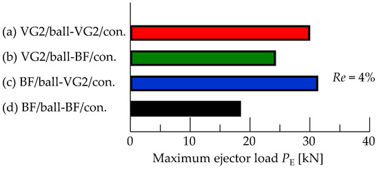
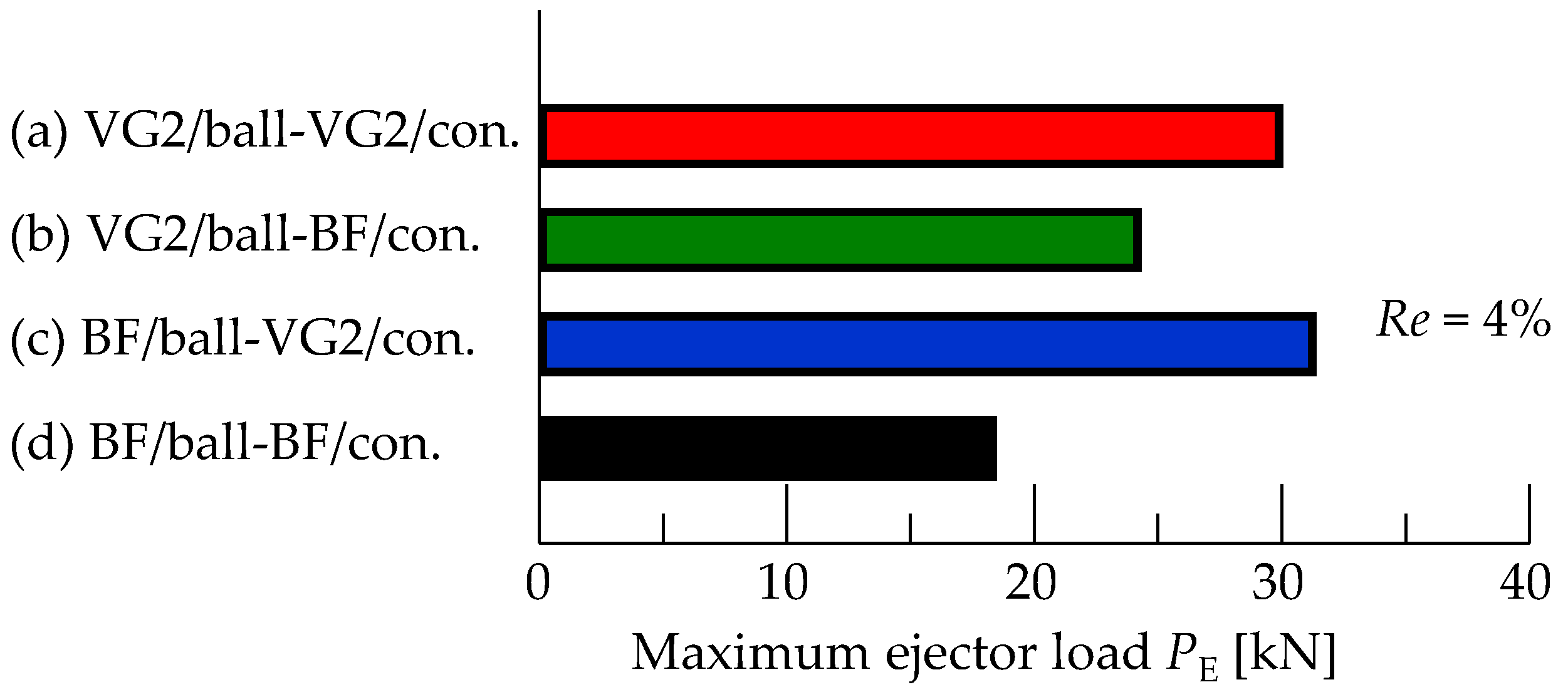
Figure 8 shows the maximum ejection force PE during ejection of the workpiece under different conditions. The workpiece was ejected from the container after the ball penetration operation. The ejection force was measured as the frictional force between the deformed workpiece and the elastically shrinking container immediately after the ball penetration. A large ejection force indicates high friction between the workpiece and the container due to high pressure or a high coefficient of friction. When VG2 is applied to the container, i.e., under conditions (a) VG2/ball-VG2/con. or (c) BF/ball-VG2/con., both conditions show the largest PE of about 30 kN. This means that lubricating the container with VG2 is not sufficient to reduce the friction between the workpiece and the container even if the ball is lubricated with beef fat, which possesses high lubricity. When beef fat (BF) is applied to the container, i.e., under conditions (b) VG2/ball-BF/con. or (d) BF/ball-BF/con., beef fat applied to the ball is more effective than VG2 in reducing PE. Based on the estimated pressure between the ball and the workpiece, the higher pressure elastically expands the container hole during the ball penetration. This elastic deformation of the container induces higher pressure between the workpiece and the container at the ejection stage. Beef fat is more effective in reducing the friction between the workpiece and the container than VG2 because of its direct lubrication performance during the workpiece ejection, as well as the indirect pressure effect during the ball penetration.
Figure 8.
Ejection forces after ball penetration.
3.4. Distribution of Equivalent Strain in the Workpiece by FEM Analysis
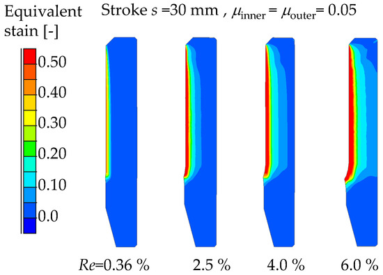
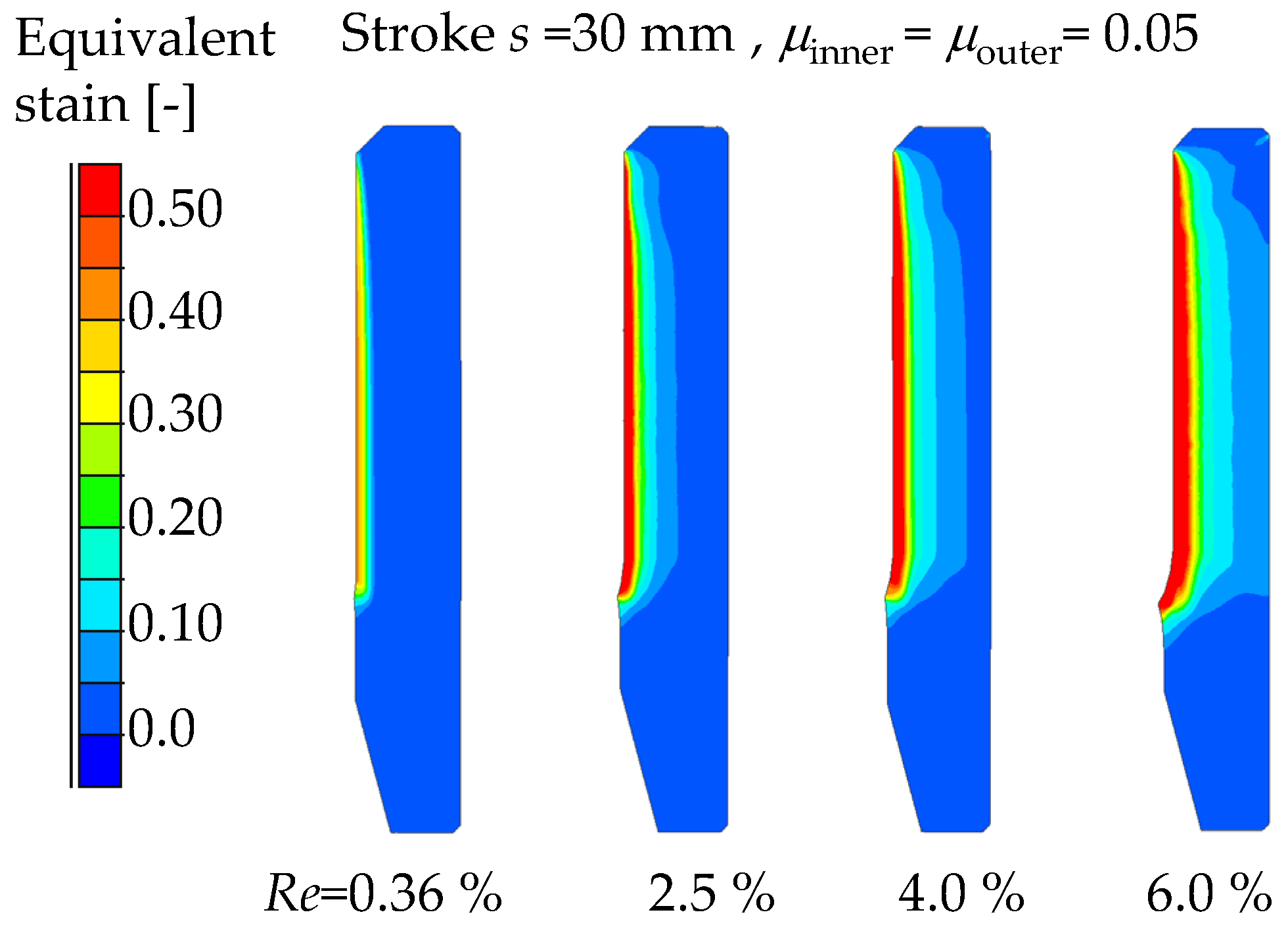
Figure 9 shows the typical distribution of the equivalent strain at a stroke of 30 mm. According to the results in Figure 7, the loads show large differences under the different lubrication conditions. The frictional coefficient μinner is assumed for the contact between the workpiece and the ball. Another frictional coefficient, μouter, is assumed between the workpiece and the container. The first example is analyzed under a well-lubricated condition using μinner = μouter = 0.05 based on the result of the ring compression test using beef fat. The strain is almost equal to zero near the outer surface of the workpiece when the cross-sectional reduction Re = 0.36%. This means that the workpiece does not contact the container during ball penetration at the small Re of 0.36%. Therefore, friction does not occur between the workpiece and the container during this operation. The strain is so small that plastic deformation occurs only near the inner surface. Thus, the workpiece holds its initial length and outer diameter. The strain area expands toward the outer side with increasing Re. Therefore, the workpiece contacts the container when Re > 2.5%, and friction occurs between the workpiece and the container. The workpiece easily elongates under well-lubricated conditions when Re > 2.5%. In addition, the workpiece expands in the radial direction. The diameter of the workpiece is larger than the inner diameter of the container after ejection. These results mean that plastic deformation extends throughout the workpiece from the inner surface to the outer surface under a well-lubricated condition when Re > 2.5%.
Figure 9.
Distribution of equivalent strain at stroke of 30 mm under different experimental conditions.
3.5. Inner Plastic Deformation of the Workpiece in the Experiment and FEM Analysis
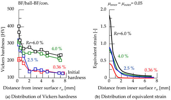
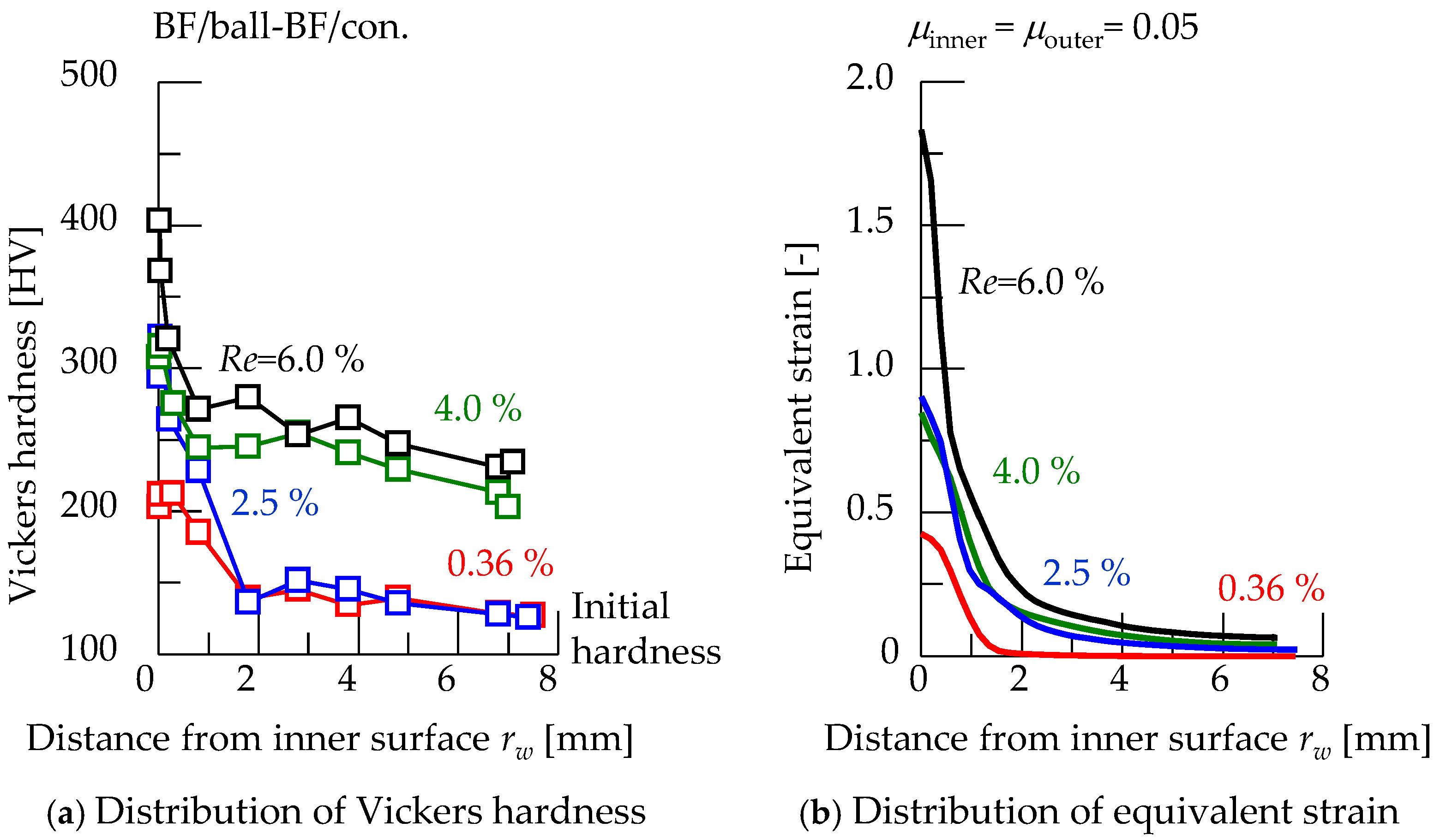
After ball penetration, the difference in plastic deformation in the workpiece is estimated by measuring the hardness distribution. Figure 10a shows the distribution of Vickers hardness in the radial direction. The hardness is measured on a typical 17 mm lower cross-sectional plane from the top end of the workpiece. Higher hardness is indicated near the inner surface after ball penetration, and it increases as Re increases. When Re = 4.0% and 6.0%, the hardness also increases near the outer side. However, when Re = 0.36% and 2.5%, the hardness is lower and close to the initial hardness. The plastic deformation expands sufficiently to the outer side at high Re, but no plastic deformation reaches the outer side at low Re. Figure 10b shows the distribution of the equivalent strain in the radial direction analyzed by FEM. The distribution of the hardness qualitatively corresponds to the distribution of the equivalent strain. Both the hardness and the equivalent strain are extremely large near the inner surface of the workpiece. These values increase with increasing Re due to work hardening. This is an effect of additional shear strain near the inner surface caused by the friction between the ball and the workpiece.
Figure 10.
Inner plastic deformation of the workpiece after ball penetration.
3.6. Relationship Between Bulge Height and Ball Penetration Load
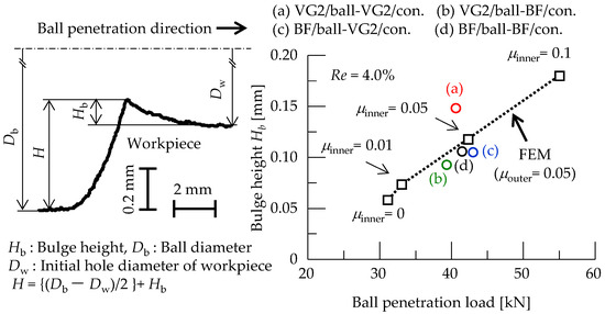
During ball penetration, the workpiece is basically elongated in the axial direction while its thickness is reduced under well-lubricated or low-friction conditions. However, under high-friction conditions, the length of the workpiece does not increase, and the bulge height increases. High friction causes the bulge to grow near the region where the ball contacts the workpiece. The bulge height, Hb, is determined as shown in Figure 11. The bulge height is defined as follows:
where Hb is the bulge height, H is a measured value, Db is the ball diameter, and Dw is the initial hole diameter of the workpiece. Figure 11 shows the relationship between the bulge height and the ball penetration load at a stroke of 28 mm. The ball was pushed to a stroke of 28 mm under the lubrication conditions in Table 2. The FEM analysis results are also shown for reference. In the FEM analysis, μouter was fixed at 0.05, and four values of μinner were used: 0, 0.01, 0.05, and 0.10, where μouter is the frictional coefficient between the container and the workpiece, and μinner is the frictional coefficient between the ball and the workpiece. According to the results of the FEM analysis, the penetration load at a stroke of 28 mm increases with increasing μinner, and the bulge height increases with increasing load, as shown in Figure 11. The experimental results under lubrication conditions (b), (c), and (d), as shown in Table 2, are consistent with the numerical estimation except for condition (a). The growing bulge causes a larger contact angle, so that the lubricant oil is difficult to supply to the hydrodynamic clearance between the ball and the workpiece. The thickness of the lubricant oil film rapidly decreases. Thus, the tribological condition becomes worse.
Hb = H – {(Db – Dw)/2},
Figure 11.
Relationship between ball penetration load and bulge height at stroke of 28 mm.
3.7. Ball Penetration Load by FEM-Analysis
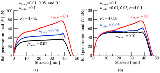
Figure 12 shows the load–stroke curves obtained by FEM analysis during the ball penetration under the frictional condition (a), as shown in Table 3. This condition consists of combinations of various μinner values ranging from 0.01 to 0.10 and a specific value of 0.10. This specific μouter of 0.10 represents the case of applying VG2 to the ball, which produces the poorly lubricated condition shown in Figure 4, Figure 5 and Figure 7. The penetration load decreases as μinner decreases. It is natural that μinner directly influences the penetration load under these frictional conditions, but the load is too low when μinner = 0.01. However, in the ball penetration operation, a μinner value of 0.01 is difficult to achieve because this operation generates more severe lubrication conditions than simple upsetting, such as in the ring compression test. Therefore, the result for a μinner value of 0.01 is not practicable, but the μinner values of 0.05 and 0.10 can be used to estimate experimental data. Condition (b), as shown in Table 3, is the combination of specific μinner = 0.10 and various μouter = 0.01–0.10. This specific μinner value represents the case of applying VG2 to the ball. The ball penetration load, however, increases mildly and remains at 50 kN stably when μouter = 0.01 is input. This μouter value of 0.01 represents well-lubricated conditions, such as when beef fat is used. Under the same condition of μinner = 0.10, the μouter values of 0.01 and 0.05 show smaller loads than the μouter value of 0.10. Therefore, applying high-performance oil to the ball as well as the container is effective for reducing the ball penetration load. Using a well-lubricated ball is reasonable, but it is surprising that using a well-lubricated container is also helpful for ironing. As the outer side of the workpiece is not under severe frictional conditions, this effect might sometimes be overlooked.
Figure 12.
Ball penetration load curves under frictional conditions of (a,b).
3.8. Change in Bulge Height and Ball Penetration Load Under Different Frictional Conditions
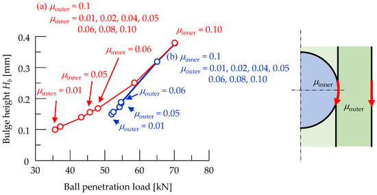
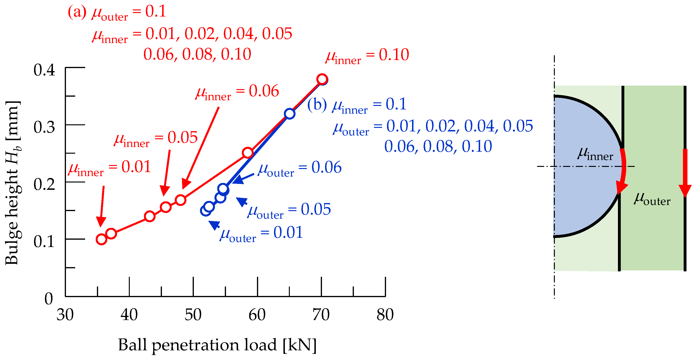
Figure 13 shows the relationship between the ball penetration load and the bulge height at a stroke of 30 mm. The workpiece flows upward relative to the die and the container. Thus, the direction of the frictional force acting on the ball and the container is downward. Condition (a) indicates the results of the combinations of various μinner values ranging from 0.01 to 0.10 and a specific μouter value of 0.10. The bulge height is 0.10–0.17 mm, and the ball penetration load is 36–48 kN when the value of μinner is 0–0.06. Condition (b) indicates the results of the combinations of various μouter values ranging from 0.01 to0.10 and a specific μ inner value of 0.10. The bulge height is 0.15–0.19 mm, and the ball penetration load is 52–55 kN when the value of μouter is 0–0.06. The bulge height and the ball penetration load increase rapidly when μouter is larger than 0.06. During the ball penetration test, material flows in front of and behind the ball. The flow of material toward the rear of the ball is prevented, while the flow of material toward the front of the ball improves under high friction between the container and the workpiece. Thus, material moves toward the center of the penetration axis. Near the container, it settles axially. Compression of the front section of the ball increases its cross-sectional area, causing the penetration load to rapidly increase. On the other hand, the flow of material toward the rear of the ball improves, while the flow of material toward the front section of the ball is prevented under low friction between the container and the workpiece. This prevents bulge deformation and an increase in the cross-sectional area, and a steady, low ball penetration load is obtained. Therefore, reducing μouter is effective in reducing both the growth of the bulge and the load.
Figure 13.
Between ball penetration load and bulge height at stroke of 30 mm.
4. Conclusions
Differential lubrication was tentatively applied to the ironing process to enable the use of possibly lower-viscosity oil, which can be helpful in reducing environmental impact and process problems. The results are summarized as follows:
- Beef fat showed high performance in inner-surface ironing using the ball penetration operation. The low-viscosity pure mineral oil, VG2, however, could not achieve favorable ironing. Using regional lubrication, in which the ball and the container were lubricated with VG2 and beef fat, respectively, a low ironing load was achieved, and a fine surface of the workpiece was obtained. In addition, by applying differential lubrication, the applicability of the low-viscosity lubricant oil was expanded from a reduction in cross-sectional area of 0.36% to 4%.
- In the inner-surface ironing with a constrained outer surface, a high resistance force was generated by the friction between the workpiece and the container during ironing. Reducing the frictional resistance contributes to easier material flow in the backward direction and controls an increase in load. Applying beef fat to the container helps reduce the frictional resistance between the workpiece and the container.
- Applying high-performance beef fat to the container is effective in reducing friction, promoting the elongation of the workpiece, and controlling the development of bulging, even if the low-viscosity oil VG2 is applied to the ball as an ironing tool. Finally, a precise product can be formed by ironing under a more ecological lubrication condition.
Author Contributions
Conceptualization, K.A. and K.K.; methodology, K.A. and K.K.; software, K.A.; validation, K.A., K.K. and T.N.; formal analysis, K.A., K.K. and T.N.; investigation, K.A., K.K. and T.N.; resources, K.A. and K.K. data curation, K.A., K.K. and T.N.; writing—original draft preparation, K.A.; writing—review and editing, K.K.; visualization, K.A.; supervision, K.K. All authors have read and agreed to the published version of the manuscript.
Funding
This research received no external funding.
Data Availability Statement
The original contributions presented in this study are included in the article. Further inquiries can be directed to the corresponding author.
Conflicts of Interest
The authors declare no conflicts of interest.
References
- Kunogi, M. Extrusion Die with Movable Wall. Trans. Jpn. Soc. Mech. Eng. 1957, 23, 757–763. [Google Scholar] [CrossRef] [Scilit]
- Nakamura, T. Research on Extrusion Process with Effective Sttick Frcition (1st Reprt, Theoritical Analsys on Forming of Thin-Wall Cup). Trans. Jpn. Soc. Mech. Eng. C 1987, 53–486, 482–487. [Google Scholar] [CrossRef] [Scilit]
- Kasuga, Y.; Nozaki, N.; Kondo, K. Pressure Lubricated Deep Drawing. Bull. JSME 1961, 4, 394–405. [Google Scholar] [CrossRef] [Scilit]
- Atala, H. Effect of Differential Lubrication on the Cup Drawing of Mild Steel Blanks. Wear 1990, 139, 171–176. [Google Scholar] [CrossRef] [Scilit]
- Hassan, M.A.; Takakura, N.; Yamaguchi, K. Friction aided deep drawing of sheet metals using polyurethane ring and auxiliary metal punch. Part 1: Experimental observations on the deep drawing of aluminium thin sheets and foils. Int. J. Mach. Tools Manuf. 2002, 42, 625–631. [Google Scholar] [CrossRef] [Scilit]
- Hassan, M.A.; Hino, K.; Takakura, N.; Yamaguchi, K. Friction aided deep drawing of sheet metals using polyurethane ring and auxiliary metal punch. Part 2: Analysis of the drawing mechanism and process parameters. Int. J. Mach. Tools Manuf. 2002, 42, 633–642. [Google Scholar] [CrossRef] [Scilit]
- Hassan, M.A.; Takakura, N.; Yamaguchi, K. Friction aided deep drawing using newly developed blank-holder divided into eight segments. Int. J. Mach. Tools Manuf. 2003, 43, 637–646. [Google Scholar] [CrossRef] [Scilit]
- Celik, I.; Sensoy, A.T.; Seven, G.; Cicek, D. Improving Deep Drawing Quality of DD13 Sheet Metal: Optimization of Process Parameters Using Box–Behnken Design. Materials 2025, 18, 1424. [Google Scholar] [CrossRef] [Scilit] [PubMed]
- Matras, A. Application of Response Surface Methodology for Modeling and Optimization of the Top Surface Ironing Process in Parts Produced by MEX 3D Printing. Materials 2025, 18, 5248. [Google Scholar] [CrossRef] [Scilit] [PubMed]
- Zuo, X.; Lv, Z. Influence of Ironing Roller on the Wrinkling of a 4N6 Aluminum Foil during the Coiling Process of Cleaning Line. Metals 2024, 14, 1073. [Google Scholar] [CrossRef] [Scilit]
- Abe, Y.; Mori, K.; Hatashita, F.; Shiba, T.; Daodon, W.; Osakada, K. Improvement of seizure resistance in ironing of stainless steel cup with cermet die having fine lubricant pockets. J. Mater. Process. Technol. 2016, 234, 195–207. [Google Scholar] [CrossRef] [Scilit]
- Abe, Y.; Sugiura, K.; Mori, K. Ironing limit of aluminium alloy cups with lubricants containing nanoparticles and tool steel die. Procedia Manuf. 2020, 50, 114–118. [Google Scholar] [CrossRef] [Scilit]
- Tan, C.J.; Abe, Y.; Daodon, W.; Takahashi, N.; Mori, K.; Purbolaksono, J. Increase in ironing limit of aluminium alloy cups with lubricants containing nanoparticles. J. Mater. Process. Technol. 2016, 2, 804–813. [Google Scholar] [CrossRef] [Scilit]
- Wang, Z.; Dohda, K.; Jeong, Y. FEM simulation of surface smoothing in the ironing process. J. Mater. Process. Technol. 2001, 113, 705–709. [Google Scholar] [CrossRef] [Scilit]
- Stone, E.R.H.; Caia, J.; Hu, Z.M.; Dean, T.A. An exercise in cold ironing as the post-forging operation for net-shape manufacture. J. Mater. Process. Technol. 2003, 135, 278–283. [Google Scholar] [CrossRef] [Scilit]
- Takaki, T.; Ito, S.; Kitamura, K.; Yagishita, K.; Shimata, J. Evaluation of anti-galling property of sulfurized olefins with overbased calcium sulfonates on stainless steel by cup internal ironing test. Procedia Eng. 2017, 207, 2292–2297. [Google Scholar] [CrossRef] [Scilit]
- Kawai, N.; Dohda, K.; Saito, M.; Hayashi, N.; Wan, Z. Friction Behavior in the Cup Ironing Process of Aluminum Sheets. J. Eng. Ind. 1992, 114, 175–180. [Google Scholar] [CrossRef] [Scilit]
- Wu, Y.; Recklin, V.; Groche, P. Strain Induced Surface Change in Sheet Metal Forming: Numerical Prediction, Influence on Friction and Tool Wear. J. Manuf. Mater. Process. 2021, 5, 29. [Google Scholar] [CrossRef] [Scilit]
- Trzepieciñski, T.; Szwajka, K.; Szewczyk, M. Analysis of Surface Topography Changes during Friction Testing in Cold Metal Forming of DC03 Steel Samples. Coatings 2023, 13, 1738. [Google Scholar] [CrossRef] [Scilit]
- Kitamura, K.; Ohmori, T.; Kawamura, M.; Danno, A. A New Cold Forging Oil and its Galling Prevention Property. Adv. Technol. Plast. 1990, 1, 41–46. [Google Scholar]
- Groche, P.; Kramer, P.; Bay, N.; Christiansen, P.; Dubar, L.; Hayakawa, K.; Hu, C.; Kitamura, K.; Moreau, P. Friction coefficients in cold forging: A global perspective. CIRP Ann. 2018, 67, 261–264. [Google Scholar] [CrossRef] [Scilit]

Disclaimer/Publisher’s Note: The statements, opinions and data contained in all publications are solely those of the individual author(s) and contributor(s) and not of MDPI and/or the editor(s). MDPI and/or the editor(s) disclaim responsibility for any injury to people or property resulting from any ideas, methods, instructions or products referred to in the content. |
© 2026 by the authors. Licensee MDPI, Basel, Switzerland. This article is an open access article distributed under the terms and conditions of the Creative Commons Attribution (CC BY) license.