Article

Impact of Mixed Convection and Lubricated Surface on Ellis Fluid Flow in a Periciliary Layer


by
Abdul Majeed Siddiqui
1,
Mehwish Ahmed
2,
Muhammad Israr Siddiqui
3 and
Khadija Maqbool
2,*
1
Department of Mathematics, Pennsylvania State University, York Campus, 1031 Edgecomb Avenue, York, PA 17403, USA
2
Department of Mathematics and Statistics, International Islamic University, Islamabad 44000, Pakistan
3
NUST Institute of Civil Engineering, National University of Sciences and Technology, Islamabad 44000, Pakistan
*
Author to whom correspondence should be addressed.
Lubricants 2026, 14(8), 309; https://doi.org/10.3390/lubricants14080309
Submission received: 29 May 2026 / Revised: 4 August 2026 / Accepted: 10 August 2026 / Published: 12 August 2026

Abstract

Ciliary-driven flow refers to the movement of fluid by the rhythmic and coordinated beating cilia and finds applications in the respiratory tract, fallopian tube, embryonic node, brain ventricles, paranasal sinuses, and understanding flows in the auditory tube. Previous research on cilia-driven flow has demonstrated forced convective flow with no-slip boundary conditions, which is crucial in mucus clearance and is not firmly stuck to the periciliary layer. This paper develops the mixed convective flow of Ellis fluid near the periciliary layer with a lubricated surface. The partial slip boundary condition provides reduced friction near the periciliary layer for the Ellis fluid flow. The momentum and energy equations are simplified by the lubrication approach, and the resulting problem is solved analytically. This research achieves the exact solutions for the temperature and velocity profiles for the consistency index 3. The findings show that the mucus flow along the lubricated surface is enhanced by the slip parameter and viscosity (shear-thinning fluid) parameter beta, but the flow across the trachea decays due to the slip and viscosity parameters. The mucus temperature rises due to the radiation and Prandtl number, which also help to reduce the frictional forces near the periciliary layer and facilitate faster mucociliary clearance.

1. Introduction

Mucus in the respiratory tract has an essential protective function by trapping inhaled dust, particulate matter, and microorganisms. Biologically, mucus is a complex fluid composed of glycoproteins (mucins) and is classified as a non-Newtonian shear thinning/ thickening fluid that can flow by ciliary movement using the no-slip condition. But the no-slip condition does not work for the complex fluid model due to high and strain-rate-dependent viscosity; therefore, few studies have used Navier slip boundary conditions in theoretical and computational models [1,2,3,4] of non-Newtonian fluids, such as blood and certain types of mucus where lubrication might be more pronounced at boundaries. The Navier slip conditions involve both velocity and its derivative in the normal direction and are useful for predicting flow near a ciliated surface. This condition permits partial slip at the boundary, and it allows a tangential velocity difference between the cilia tip and complex fluid flow. This condition is more practical for biological systems where fluid layers or porous tissues reduce surface adhesion. The impact of the slip condition on ciliary flows has been studied by a number of researchers, who have shown significant variations in temperature, pressure, and velocity distributions [5,6,7,8] and found that slip parameters control the flow and pressure in the fluid. The physiological basis for this partial-slip assumption lies in the structure of the periciliary layer (PCL), the low-viscosity fluid layer that lies beneath the mucus and lubricates ciliary beating. Cilia tips do not maintain continuous, rigid contact with the overlying mucus layer during each beat cycle [9,10]. The slip parameter in the present model is consistent with the physiologically low viscosity nature of the periciliary layer relative to the mucus above it.
In this study, the Ellis fluid model is considered as an effective and realistic representation of biological fluid (mucus) that exhibits shear-thinning behavior. Since ciliary motion naturally occurs in shear-thinning types of fluids, the Ellis fluid model serves as an appropriate framework for analyzing cilia-driven transport phenomena. The non-Newtonian characteristics of Ellis fluid, in which viscosity decreases with increasing shear rate, closely mimic the rheological behavior of biological secretions found in respiratory and reproductive systems [11,12]. In recent years, numerous researchers have investigated Ellis fluid flow in the context of wavy motion, exploring the effects of heat and mass transfer, surface roughness, and magnetic influences on fluid behavior. For example, Zafar et al. [13] compared the effects of heat radiation and viscous dissipation on wavy and straight boundaries in a two-phase Ellis fluid flow via a horizontal tube. The combined impacts of thermal radiation, bio-heat transfer, and wavy motion under convective boundary conditions have also been examined in the context of Ellis fluid flow in a ciliated tube by Channakote et al. [14]. Abbasi et al. [15] analyzed the peristaltic motion of Ellis fluid in an asymmetric channel, under the effects of chemical reactions within a confined flow regime. Furthermore, the Ellis model has been extended to multi-layer (bi-layer and tri-layer) fluid structures to represent interactions between dissimilar biofluids, such as mucus-based layering in respiratory tracts or separated secretions in reproductive channels. Thus, including the multi-layer Ellis formulation gives a more complete and physiologically consistent framework for modeling actual biofluid movement [16].
In free convection, fluid motion is driven purely by density differences created by temperature gradients with no external source, while in forced convection, flow is imposed externally (like ciliary beating itself, or airflow from breathing); also, both free and forced convective flow produce mixed convective flow. Mucus is transported mainly by metachronal beating of cilia, and its viscosity is sensitive to temperature. Convective heat transfer that dries or cools the mucus layer increases its viscosity, making it harder for cilia to propel and reducing mucociliary clearance efficiency. Also, there is a thin periciliary liquid (PCL) layer and an overlying mucus layer, both maintained by water transport. The heat exchanged between the PCL and mucus layer creates a thermal gradient across the trachea, which generates the buoyancy-driven flow on ciliary-driven mucus transport. Besides the fluid viscosity, ciliary activity also depends on temperature, and its beat frequency (CBF) is highly temperature sensitive. Experimental studies [17] have shown that CBF in respiratory cilia increases linearly when temperature rises from 20 °C to 37 °C, and it decreases when temperature decreases from 37 °C to 32 °C. Also, CBF decays when the temperature in the respiratory tract becomes high, i.e., beyond 40–45 °C. For better performance of mucus clearance, CBF must work in optimum conditions that can be availed when the temperature is 35–37 °C; therefore, temperature change is compulsory in mucus flow. Shaheen et al. [18] observed the mucus flow with forced convective heat transfer using mucus as a Maxwell fluid with no-slip boundary condition near the ciliated surface and found that the inertial forces accelerate the flow along the trachea length. Maqbool et al. [19] observed the heat and magnetic effects on the mucus clearance using the Carreau fluid model and observed that mucus flow is highly influenced by the temperature gradient and magnetic field. Two-layer ciliary flow with heat and mass transfer has been discussed by Shaheen et al. [20] for the Ellis fluid model but observed the forced convective flow using no-slip boundary conditions. Recently, Maqbool et al. [21] studied the bilayer diffusive convective flow using the Williamson fluid model and observed the temperature gradient by the ciliary activity. Tanveer et al. [22] illustrated the magnetohydrodynamic Carreau fluid flow and heat transfer in a fallopian tube due to the metachronal wave of cilia. A recent study on the peristaltic flow of Rabinowitsch nanofluid through a ciliated tube highlighted the influence of heat and mass transfer on biofluid flow [23]. Numerous researchers have explored heat transfer characteristics in non-Newtonian biological fluid models and examined the combined effects of thermal radiation and convective boundary conditions to better understand the temperature distribution in ciliary flows [24,25,26,27,28]. A few more studies in the literature have examined cilia-driven flows of forced and free convection, highlighting the significant role of buoyancy and thermal effects on biofluid dynamics [29,30].
Building on previous studies of cilia-driven bio-fluid flow it is noticed that mixed convection for Carreau, Ellis and Bingham plastic fluid has been ignored with no slip condition only Bingham plastic study is available with slip boundary condition but ignoring the mixed convection as mentioned in Table 1, the present work develops an analytical model for the flow of Ellis fluid in a ciliated trachea that includes the effects of mixed convection and Navier-slip boundary conditions. This model explains how slip conditions, shear-thinning behavior, and temperature differences together influence mucus flow. Exact solutions are obtained for the mucus flow measured by velocity field, pressure gradient, volumetric flow rate, and stream function. The graphical results display how the Ellis fluid and slip parameters affect the velocity profiles, pressure distribution, and streamline patterns of mucus, giving a better understanding of heat and fluid transport in biological and microfluidic systems.

2. Formulation of the Problem

Assume that a two-dimensional channel in the ( X ∗ , Y ∗ ) coordinate system resembles a trachea which is filled with mucus (Ellis Fluid) and anchored with the cilia as mentioned in Figure 1. The back-and-forth motion of the ciliary tip due to backward and forward strokes forms a wavy motion along the channel length. For ciliary propulsion, different approaches are available in the literature [32], but in this study, the envelope model approach is used for the locomotion of bio-fluid near the ciliary surface. The ciliary tip is located at ( X 0 ∗ , a) and follows an elliptical path and satisfies the following parametric equations as mentioned by Saleigh et al. [32].
X ∗ = f ( X ∗ , t ∗ ) = X 0 ∗ + a ε α 1 sin 2 π X ∗ − c t ∗ λ ,
Y ∗ = h X ∗ , t ∗ = a + a ε c o s 2 π X ∗ − c t ∗ λ ,            
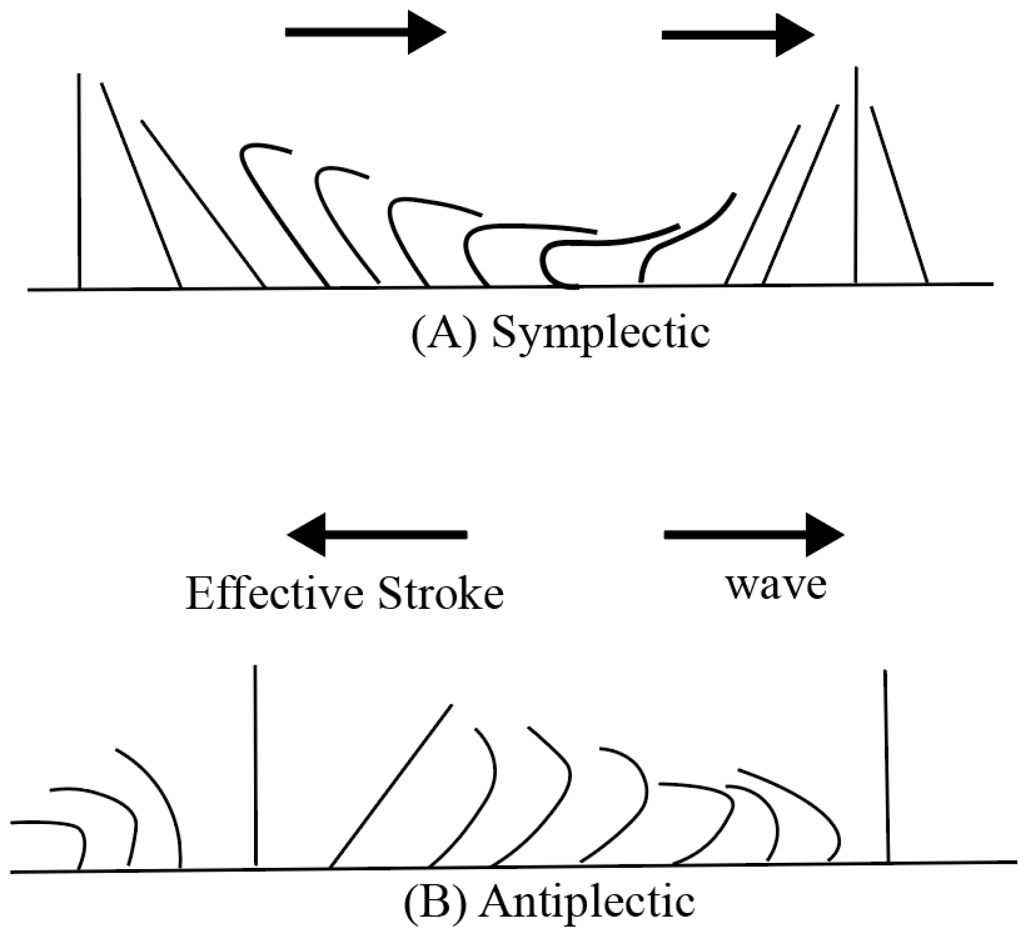
where ε is a non-dimensional cilia length parameter,   α 1 is the eccentricity of the elliptical path, λ and c are the wavelength and wave speed of the metachronal wave, respectively, and 2 π X ∗ λ is the phase shift and produces the symplectic wave if − π < 2 π X ∗ λ < 0 and antiplectic wave if 0 < 2 π X ∗ λ < π as displayed in Figure 2.
The mucus flow in a trachea suggests the following velocity profile:
V ∗ = U ∗ X ∗ , Y ∗ , t ∗ , V ∗   X ∗ , Y ∗ , t ∗ , 0 ,
where U ∗ and V ∗ are mucus velocities along and across the channel, respectively.
The mixed convective flow of mucus (Ellis fluid) through a trachea anchored with cilia can be observed by the following laws of fluid mechanics:
∇ . V ∗ = 0 ,
ρ ∗ d V ∗ d t ∗ = d i v τ   +   ρ ∗ b ,
ρ ∗ c p d T d t ∗ = K ∇ 2 T + Q 0 ,
where ρ ∗   denotes mucus density, b is the buoyancy force due to temperature difference, c p is the specific heat of mucus, K is the thermal conductivity of the mucus and considered to be constant, Q 0 is the heat source, and τ   is the stress tensor for Ellis fluid [12,13,14] and is given as follows:
τ = − P ∗ I + S ,
S = μ 1 + L s S 0 α − 1 A 1 ,
where
A 1 = grad V ∗ + g r a d V ∗ t ,
S 0 = μ 2 ,
L s = 1 2 t r A 1 2 ,
P ∗ is the pressure, I represents the identity tensor,   S is the extra stress tensor for an Ellis fluid, μ is the dynamic viscosity, α is the consistency index, L s is a second-order invariant tensor, and A 1 is the first Rivlin-Erickson tensor.
The mucus near the cilia tip can be traced by the following axial and transverse velocities:
U ∗ = ∂ f ∂ t ∗ + ∂ f ∂ X ∗ ∂ X ∗ ∂ t ∗ = ∂ f ∂ t ∗ + ∂ f ∂ X ∗ U ∗ ,
    V ∗ = ∂ h ∂ t ∗ + ∂ h ∂ X ∗ ∂ X ∗ ∂ t ∗ = ∂ h ∂ t ∗ + ∂ h ∂ X ∗ U ∗ ,
In view of Equations (1) and (2), the above equations can be reduced into the following form:
U ∗ = − 2 π λ ϵ   α 1 a c c o s 2 π X ∗ − c t ∗ λ , 1 − 2 π λ ϵ   α a c c o s 2 π X ∗ − c t ∗ λ ,
V ∗ = 2 π λ ϵ a c s i n 2 π X ∗ − c t ∗ λ 1 − 2 π λ ϵ α 1 a c o s 2 π X ∗ − c t ∗ λ                     .
Since the cilia tip forms a wavy surface, the boundary ( − h ≤ y ≤ h ) is just like a cosine or sine wave and is represented by the following expression:
h =       a 1 + ϵ   cos 2 π X ∗ − c t ∗ λ ,
To solve the above mathematical problem, we will transform the fixed frame into the wave frame, which satisfies the following transformations:
p ∗ ( x ∗ , y ∗ ) = P ∗ X ∗ , Y ∗ , t ∗ , y ∗ = Y ∗ , x ∗ = X ∗ − c t ∗ , v ∗ = V ∗ , u ∗ = U ∗ − c                            
After using the above transformation in Equations (4)–(16), the continuity, momentum and energy equations reduce to the following form:
∂ u ∗ ∂ x ∗ + ∂ v ∗ ∂ y ∗ = 0 ,  
ρ ∗ u ∗ + c ∂ u ∗ ∂ x ∗ + v ∗ ∂ u ∗ ∂ y ∗ = − ∂ p ∗ ∂ x ∗ + ∂ τ x x ∗ ∂ x ∗ + ∂ τ x y ∗ ∂ y ∗ + ρ g β T T ∗ − T 0 ∗ ,
ρ ∗ u ∗ + c ∂ v ∗ ∂ x ∗ + v ∗ ∂ v ∗ ∂ y ∗ = − ∂ p ∗ ∂ y ∗ + ∂ τ y x ∗ ∂ x ∗ + ∂ τ y y ∗ ∂ y ∗ ,  
ρ ∗ c p u ∗ + c ∂ T ∗ ∂ x ∗ + v ∗ ∂ T ∗ ∂ y ∗ = K ∂ 2 T ∗ ∂ x ∗ 2 + ∂ 2 T ∗ ∂ y ∗ 2 + Q 0 ,
where
τ x y ∗ = μ ∗ R ∗ ∂ v ∗ ∂ x ∗ + ∂ u ∗ ∂ y ∗ ,
τ x x ∗ = 2 μ ∗ R ∗ ∂ u ∗ ∂ x ∗ ,
τ y y ∗ = 2 μ ∗ R ∗ ∂ v ∗ ∂ y ∗ ,        
R ∗ = 1 + 2 ∂ u ∗ ∂ x ∗ 2 + ∂ v ∗ ∂ y ∗ 2 + ∂ u ∗ ∂ y ∗ + ∂ v ∗ ∂ x ∗ 2 μ ∗ 2 α − 1 ,
The axi-symmetric condition of the ciliated channel (trachea) states that the flow is shear-free and satisfies the following constraints:
τ x y ∗ = 0 ,                               a t           y ∗ = 0 ,
After the locomotion of the biofluid, mucus sticks to the cilia tip and can not follow the no-slip condition; the following Navier-slip boundary condition [2,3] is required at the wavy boundary:
u ∗ − φ ∂ u ∗ ∂ y = U ∗ ,                               a t       y ∗ = h ∗ ,
U ∗ + c = − 2 π λ ε   α 1 a c c o s 2 π x ∗ λ 1 − 2 π λ ε   α 1 a c c o s 2 π x ∗ λ ,   a t       y ∗ = h ∗
V ∗ = 2 π λ ε   a c s i n 2 π x ∗ λ 1 − 2 π λ ε   α 1 a c o s 2 π x ∗ λ ,   a t       y ∗ = h ∗
The velocity gradient in the mucus at the center of the trachea is zero, and the mucus has constant temperature near the ciliated surface, which can be stated by the following constraints:
∂ T ∗ ∂ y ∗ = 0 ,                             a t         y ∗ = 0 ,
T ∗ = T 1 ,                                 a t     y ∗ = h ∗ ,
where
          h ∗ = ±       a + a   ε cos 2 π x ∗ λ ,  
It is also noted that the above problem will produce the results of mixed convection of the Newtonian fluid model with slip condition [22] when α   → 1 , and φ ≠ 0 , but for α   ≠ 1 ,   G r = 0 and φ = 0 , this model reduces to the ciliary flow of Ellis fluid under thermal effect that has already been discussed by Shaheen et al. [20].
For the physical discussion of the mathematical model, the following non-dimensional parameters are introduced:
x = x ∗ λ , y = y ∗ a , u = u ∗ c , v = v ∗ γ c , h = h ∗ a , p = a γ c μ p ∗ , γ = a λ ,   R e = ρ ∗ a c μ , P r = μ c p k ∗ ,
θ = T ∗ − T 0 ∗ T 1 ∗ − T 0 ∗ , G r = g a 3 β T T 1 ∗ − T 0 ∗ ν 2 , b = a 2 Q 0 T 1 ∗ − T 0 ∗ μ c p ,   G r t = G r R e ,
τ i j ∗ = a c μ τ i j ∗   ,           β = c a μ α − 1
Using the above parameters in Equations (18)–(32) , and after dropping primes, one can get the following form:
∂ u ∂ x + ∂ v ∂ y = 0 ,
R e γ u + 1 ∂ u ∂ x + v ∂ u ∂ y = − ∂ p ∂ x + γ ∂ τ x x ∂ x + ∂ τ x y ∂ y + G r t θ ,
R e γ 3 ( u + 1 ) ∂ v ∂ x + v ∂ v ∂ y = − ∂ p ∂ y + γ 2 ∂ τ y x ∂ x + γ ∂ τ y y ∂ y ,
P r R e γ u + 1 ∂ θ ∂ x + v ∂ θ ∂ y = γ 2 ∂ 2 θ ∂ x 2 + ∂ 2 θ ∂ y 2 + P r b ,
τ x x = 2 γ μ R ∂ u ∂ x ,
τ x y = μ R γ 2 ∂ v ∂ x + ∂ u ∂ y ,
τ y y = 2 γ μ R ∂ v ∂ y ,
Non-dimensional boundary conditions are mentioned below:
τ x y = 0 ,                               a t           y = 0 ,  
u − φ ∂ u ∂ y = u w ,                               a t           y = h ,
u w = − 2 π   ε   α 1 γ c o s 2 π x 1 − 2 π   ε   α 1 γ c o s 2 π x − 1     a t       y = h ,
v w = 2 π   ε   γ c s i n 2 π x 1 − 2 π   ε   α 1 γ c o s 2 π x ,   a t       y = h ,
Non-dimensional form of temperature distribution is as follows:
∂ θ ∂ y = 0 ,                             a t         y = 0
θ = 1                               a t     y = h ,
where
h = ±       1 + ε   cos 2 π x ,
The lubrication approach used in Refs. [21,22] reduces Equations (34)–(40) , into the following form:
− ∂ p ∂ x + ∂ τ x y ∂ y + G r t θ = 0 ,
− ∂ p ∂ y = 0 ,             p ≠ p y
∂ 2 θ ∂ y 2 + P r b = 0 ,
τ x x = 0 ,
τ x y = μ R ∂ u ∂ y ,
τ y y = 0 ,
where
R = 1 + β χ α − 1 ,
χ = 1 2 τ x x 2 + 2 τ x y 2 + τ y y 2        
with boundary conditions
τ x y = 0 ,                               a t           y = 0 ,
u − φ ∂ u ∂ y = U ,                               a t           y = h ,
U = − 2 π   ε   α 1 γ c o s 2 π x − 1 ,       a t       y = h ,    
V = 2 π   ε γ sin 2 π x + 2 π ε γ 2 α 1 sin 2 π x cos 2 π x ,   a t   y = h .
Temperature profile at the boundary is given by
∂ θ ∂ y = 0 ,                             a t         y = 0 ,
θ = 1                               a t     y = h ,

3. Solution Methodology

Solution of Equation (50) under the constraints defined in Equations (60) and (61) can be obtained by integration and is represented as follows:
θ = − P r b y 2 2 + C y + D ,
where C and D are constants of integration and are given in the following form:
C = 0 ,  
D = 1 + P r b h 2 2 ,  
After using Equations (63) and (64) in Equation (62), one can get the following parabolic temperature profile:
θ = 1 − P r b y 2 − h 2 2 .  
Now to get the velocity profile, we will rewrite Equation (48) in the light of Equation (65):
d p d x = ∂ τ x y ∂ y + G r t 1 − P r b y 2 − h 2 2 .
Upon integrating Equation (66) w.r.t y and using the boundary condition given in Equation (56), one can get the following expression for the stress component,
τ x y = d p d x y − G r t y − P r b 2 y 3 3 − h 2 y ,
Comparison of Equation (52) and Equation ( 67 ), yields the following form:
∂ u ∂ y = 1 μ F y + β α − 1 F y α  
where
F y = d p d x y − G r t y − P r b 2 y 3 3 − h 2 y .  
For a shear-thinning fluid, the consistency index can be chosen α = 3 , and for other values of α approximate solutions can be obtained, but an exact solution is not possible.
Th solution of Equation (68) together with the boundary conditions given in Equations (57) and (58) is represented as follows:
u = − d p d x 3 f 1 + d p d x 2 f 2 + d p d x f 3 + f 4  
where f 1 , f 2 , f 3 and f 4 are defined in Appendix A.
To get the transverse velocity, the following equation of continuity can be used:
∂ v ∂ y = − ∂ u ∂ x ,    
Integrating the above equation w.r.t to y and solving for v and using the boundary condition at y = 0, one can get the expression for transverse velocity v .
The following relation of velocity and stream function can be used to get the stream function ψ :
∂ ψ ∂ y = u  
∂ ψ ∂ x = − v  
After using axial and transverse velocity in Equations (71) and (72), one can get the following stream function:
ψ = ∫ v d x + y − h U + f 5 d p d x + f 6 d p d x 2 + f 7 d p d x 3
where f 5 , f 6 , f 7 are defined in Appendix A.
The volume flux across the channel can be found by the following formula:
Q = ∫ − h h u d y   ,
Q = h U + f 8 + f 9 d p d x + f 10 d p d x 2 + f 11 d p d x 3 .  
where f 8 , f 9 , f 10 and f 11   are defined in Appendix A.

4. Graphical Results

The exact solution of the model will help to visualize the impact of the viscoelastic property of the fluid by the Ellis fluid parameter   β , the lubrication effect by the slip parameter φ and thermal Grashof number G r t . for temperature and flow field. The impact of these features on the pressure gradient and stream function has also been explained for the fixed values of b = 0.3 ,   Q = 0.1 ,   α 1 = 0.4 ,   ε = 0.3 ,   μ = 0.1 ,   γ = 0.4   a n d   P r = 6.9 in the software Mathematica version 12. These values for mucus-like biological fluids are used in prior mucus-transport studies such as Shaheen et al. [20] and Maqbool et al. [19]. The cilia length ε and eccentricity parameters α1 are chosen within the physiologically realistic range used in envelope-model studies of ciliary beating, and the slip parameter range φ = 0.02–0.24 is consistent with the thin, micrometer-scale periciliary layer.

4.1. Velocity Profile

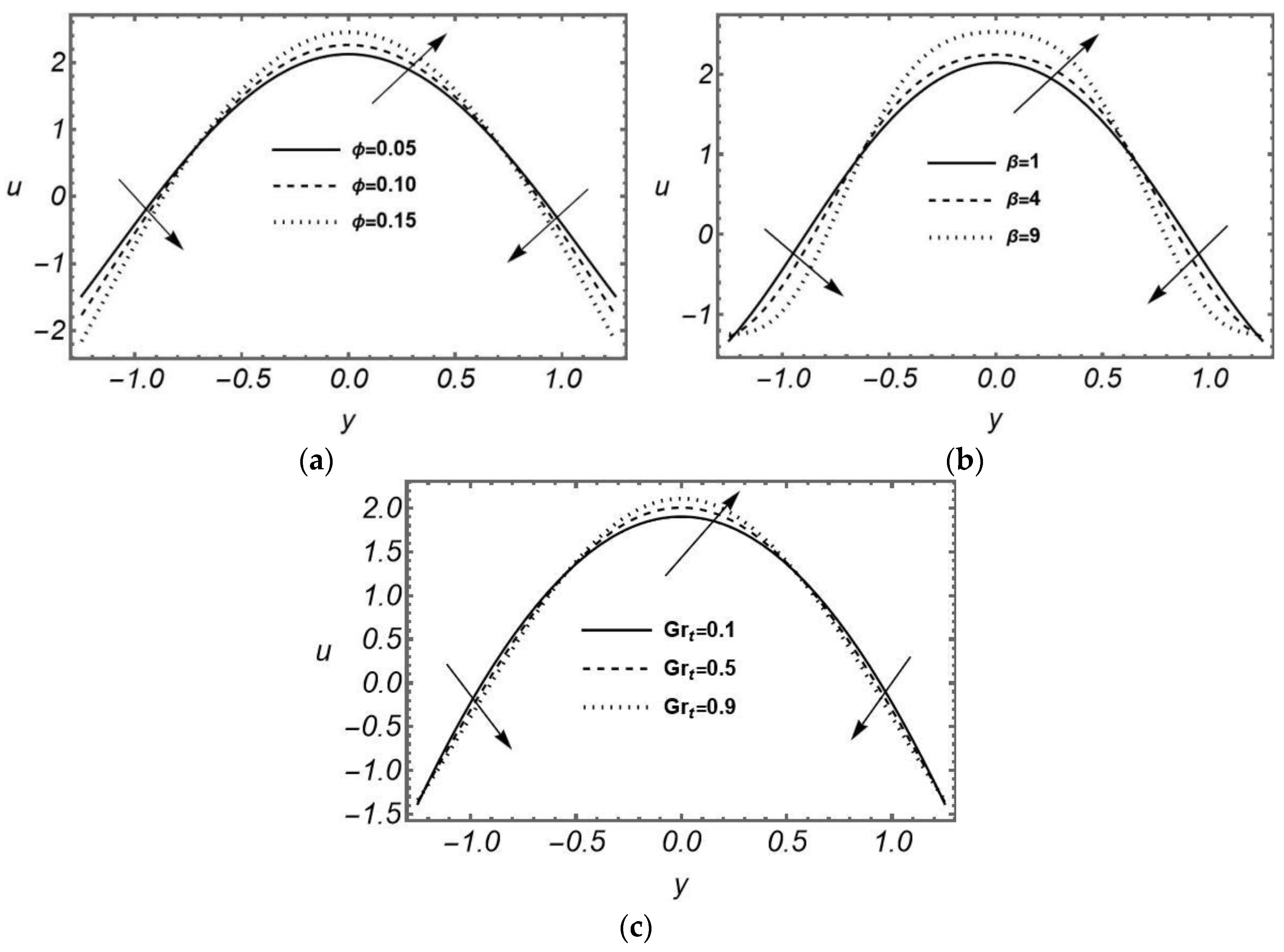
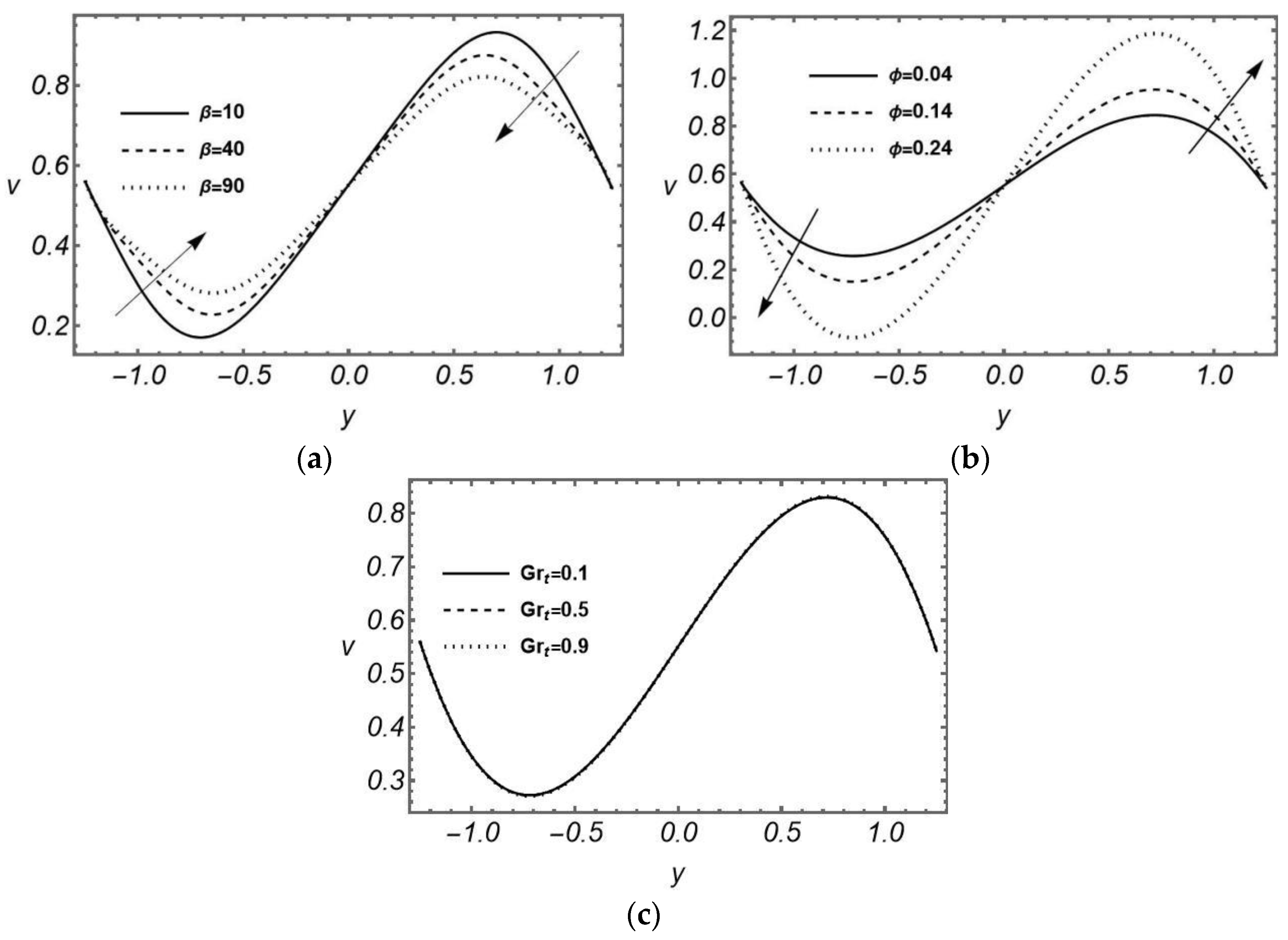
The effects of the shear-thinning parameter β of Ellis fluid, the slip parameter φ and thermal Grashof number G r t on the axial velocity u and transverse velocity v are displayed in Figure 3 and Figure 4, respectively. The mucus flow in the trachea is symmetric about the center line ( y = 0 ) , and it is noted that the mucus flow along the trachea length becomes maximum near the center of the trachea due to the least friction. Figure 3a shows lubrication near the ciliated surface due to the slip parameter (ϕ), which accelerates the mucus flow along the tracheal length shown by the upward arrow and flattens the velocity curve suggesting that the Navier-slip condition reduces the friction near the ciliated surface shown by the downward arrow. In Figure 3b, the viscosity parameter of the Ellis fluid (β) leads to accelerate the mucus flow because it reduces the effective viscosity and flow resistance through better shear-thinning action. Figure 4a illustrates the impact of the Ellis fluid parameter ( β ) on transverse velocity v which shows that the curves depict both upward and downward flow around the centerline of the trachea, and the viscosity of the mucus decelerates the flow across the trachea length due to strong resistance indicated by the downward arrow, resulting in reduced transverse motion. In Figure 4b, the impact of the slip parameter ϕ shows that flow along the tracheal width accelerates near the ciliated surface due to a lubricated surface mentioned by the upward arrow, which produces less shear resistance near the boundary. The temperature difference in mucus is measured as the buoyancy force ( G r t ) that affects the mucus flow along the trachea, as shown in Figure 3c. It displays that axial velocity increases moderately due to G r t , while the transverse velocity remains effectively unchanged across the same range in Figure 4c, indicating that the buoyancy force in the present model couples primarily to axial momentum rather than transverse momentum.

4.2. Pressure Gradient

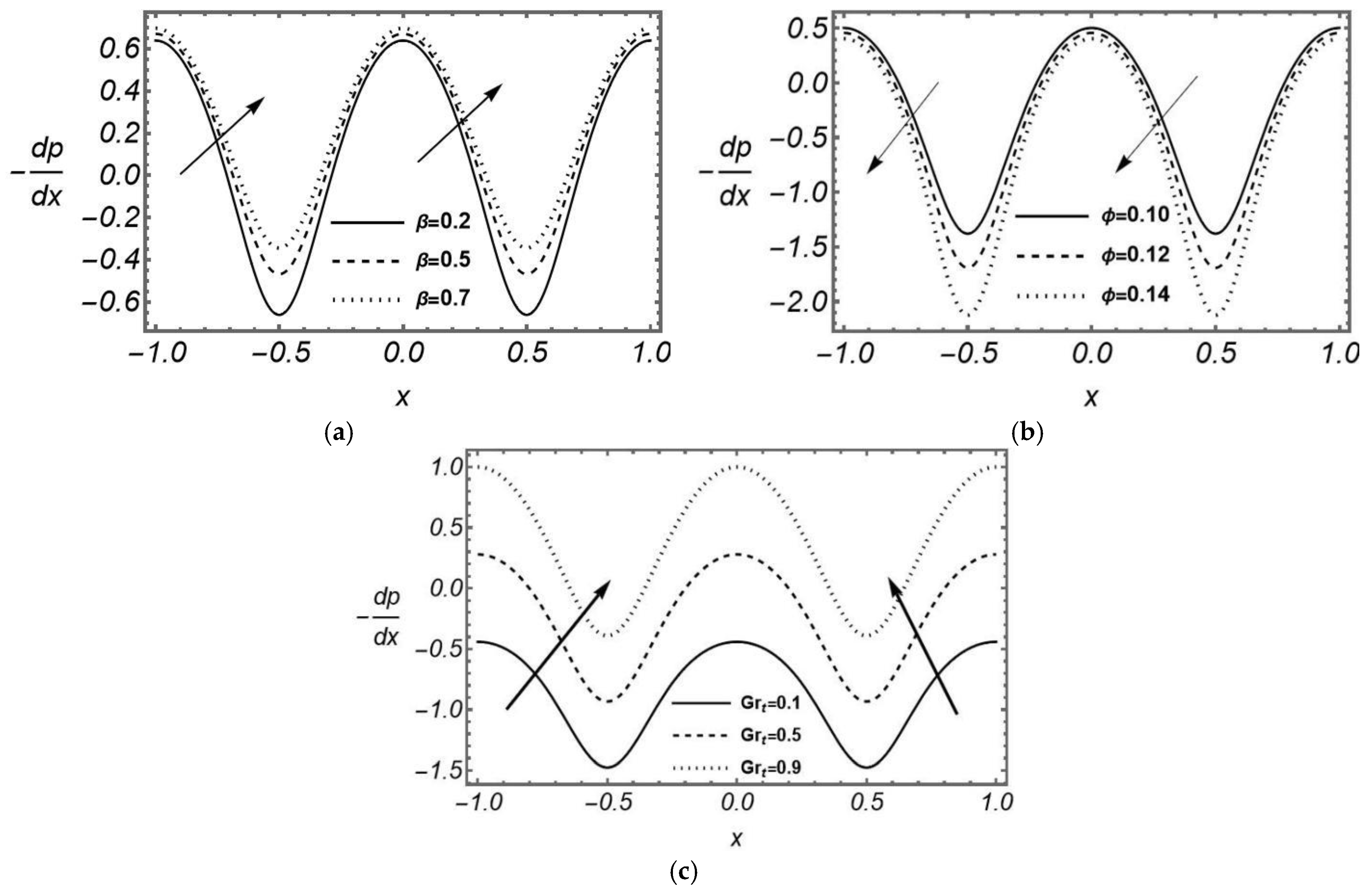
Figure 5a shows that the amplitude of the pressure gradient built up in mucus flow diminishes with the mucus viscosity represented by the parameter   β because the fast motion of mucus along the trachea length causes a small change in pressure due to the shear-thinning effect. From Figure 5b, it is observed that lubrication near the surface helps to reduce the pressure gradient as mentioned by the downward arrow, which is necessary to drive the mucus flow. Higher lubrication reduces the surface friction and permits more mucus to flow through the trachea. The increased slip amplifies pressure changes in the trachea and encourages faster mucus flow as shown by the upward arrow. Figure 5c shows the effect of buoyancy forces ( G r t ) due to temperature difference in mucus on the pressure gradient. The amplitude of the pressure gradient rises clearly and consistently with G r t , indicating that a larger driving pressure gradient is required to sustain the mucus flow as the buoyancy contribution grows.

4.3. Temperature Profile

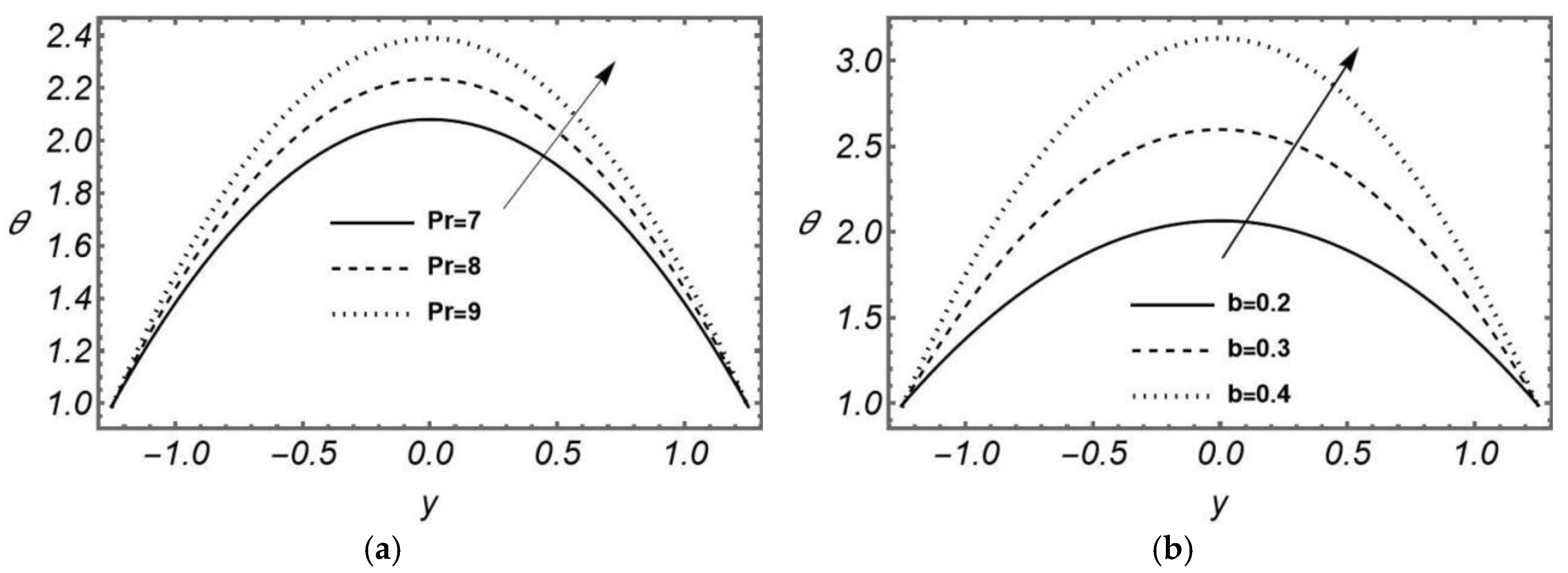
Figure 6a,b display that the temperature of the mucus in the trachea rises when the Prandtl number and radiation parameter grow as shown by the upward arrows. The kinematic viscosity is dominant over the thermal diffusivity, so the fluid particles are packed close to each other, and the transfer of heat in mucus becomes high, resulting in a rise in the temperature of mucus that causes a reduction in the resistance in mucus flow. The radiation parameter helps to increase the thermal diffusivity in the fluid; therefore, temperature rises in the mucus and supports the mucus flow.

4.4. Streamlines

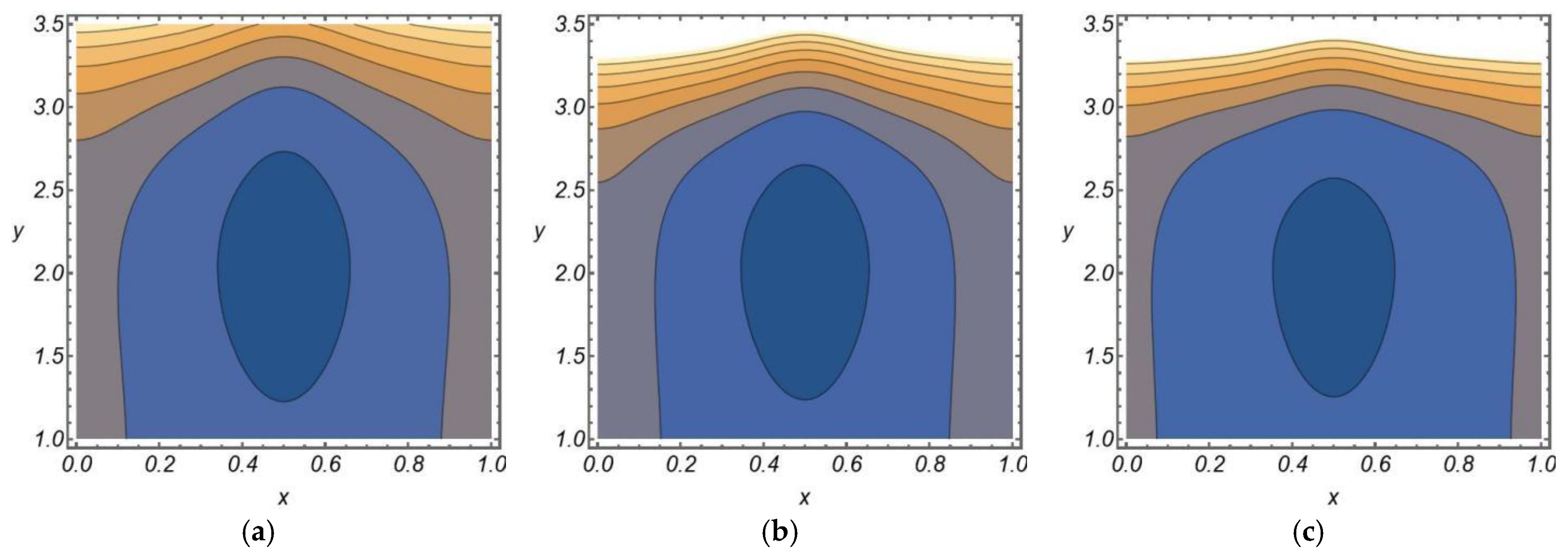
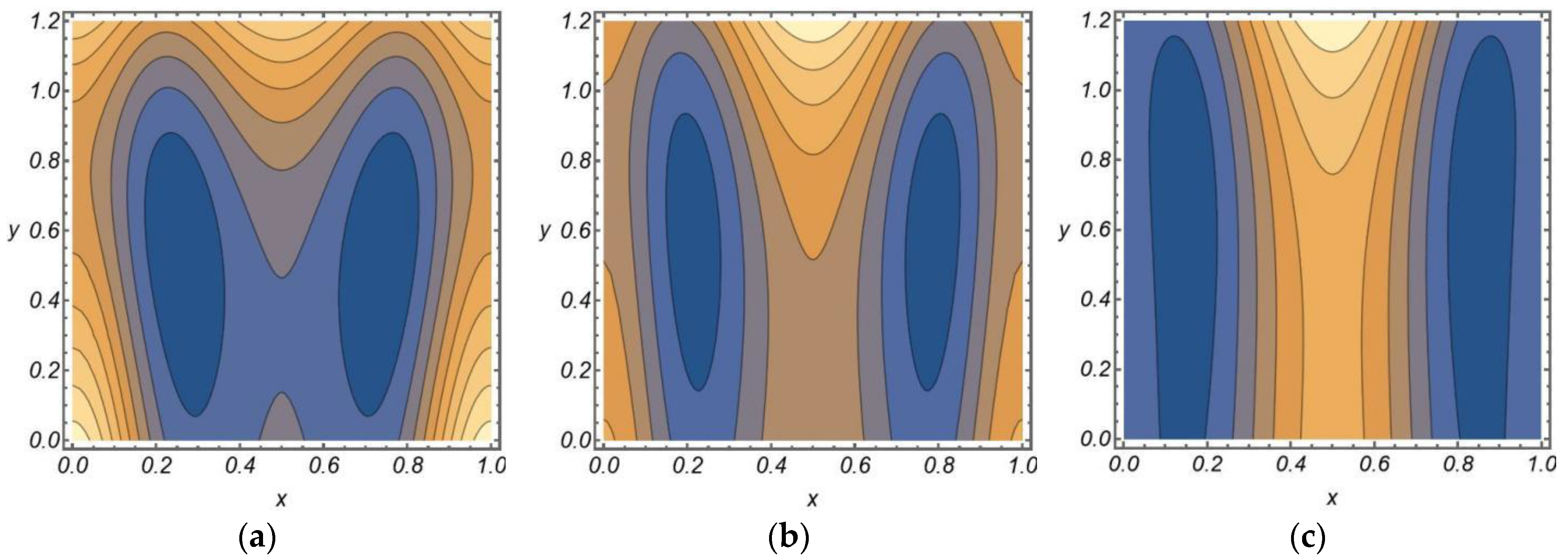
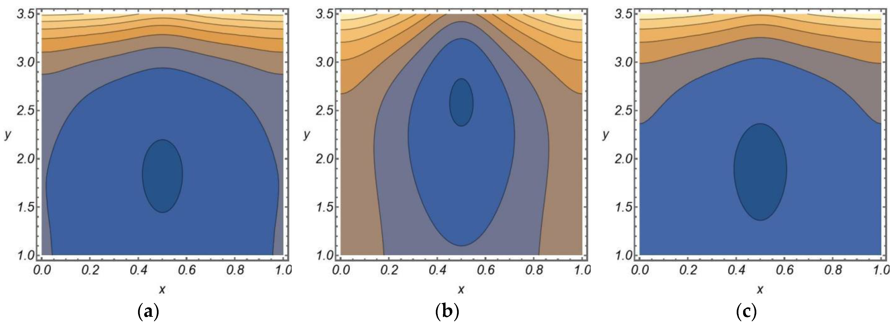
The results reveal three distinct parametric trends governing bolus formation and streamline behavior. For the mucus viscosity parameter β (Figure 7a–c), the relationship is monotonically inverse; as β increases, shear-thinning behavior weakens proportionally, causing bolus size to decrease steadily. However, at low β, high effective viscosity drives strong internal circulation, producing a large, elongated bolus with high-curvature streamlines, whereas at high β, the bolus shrinks and streamlines smooth out considerably. In contrast, the slip parameter φ (Figure 8a–c) shows a monotonically direct relationship with circulation strength. As φ increases, boundary resistance near the ciliated wall decreases, which strengthens internal circulation and increases bolus size proportionally, with streamlines spreading outward and convective flow increasing across the full range tested. The buoyancy parameter (Figure 9a–c); however, departs from this monotonic pattern entirely, bolus size is maximal at the lowest value tested, drops noticeably at the intermediate value (where the bolus also shifts spatially toward the upper boundary of the periciliary region), indicating that buoyancy’s influence on the re-circulation structure is non-linear and cannot be characterized by a simple proportional strengthening or weakening trend across its range.

4.5. Comparison of Symplectic and Antiplectic Waves

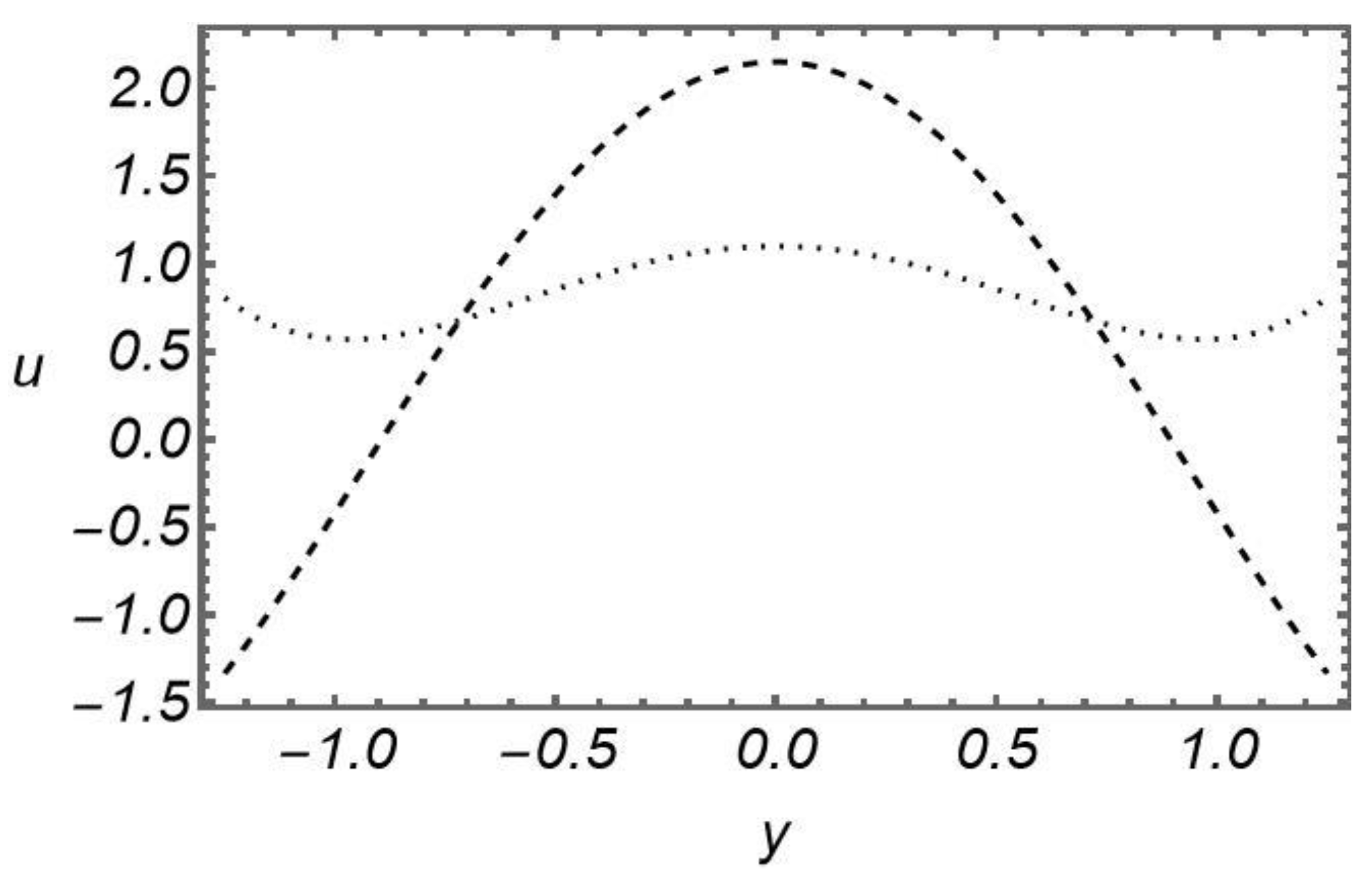
The axial velocity u along the channel is shown for both symplectic (dashed line) and antiplectic (dotted line) waves in Figure 10. The symplectic wave generates a stronger forward flow with a larger peak velocity in the channel’s center, whereas the antiplectic wave exhibits lesser transport. This study suggests that the direction of the ciliary wave has a considerable influence on the distribution of mucus flow in the trachea; therefore, for experimental purposes, the choice of the wave is very important.

4.6. Shear Stress vs. Strain Rate Graph

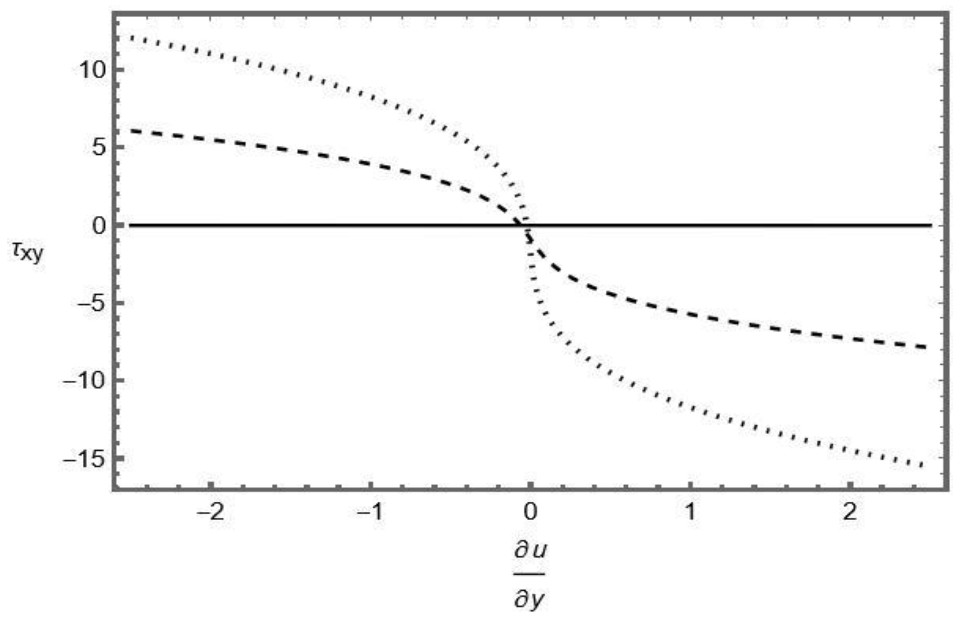
The relationship between shear stress τ x y and strain rate ∂ u ∂ y for the mucus in the trachea (Ellis fluid) is displayed in Figure 11. The fluid’s shear-thinning tendency is reflected in the graph’s nonlinear variation, where stress falls as strain rate increases. This behavior demonstrates that when the rate of deformation increases, the viscosity of Ellis fluid decays, which confirms the shear-thinning behavior of the fluid.

5. Conclusions

A mathematical model of mixed convective flow of Ellis fluid in the periciliary layer has been formulated. The resulting equations are simplified using small Reynolds number and long wavelength approximation. Exact solutions for velocity, temperature, and pressure gradient have been determined, which help to demonstrate the graphical results of flow properties against emerging parameters, and results are summarized as follows:
  • The axial flow accelerates due to the lubricated surface of the periciliary layer and shear-thinning effects of Ellis fluid.
  • The flow across the channel height shows dual behavior due to the lubricated surface and viscosity parameter of the Ellis fluid.
  • The viscosity of the Ellis fluid helps to accelerate the pressure gradient, but the lubricated surface reduces the pressure gradient.
  • The Contour size of the fluid becomes pronounced by the lubrication effect, but the viscosity of the fluid causes the bolus size to decay.
Limitations and future directions:
In this study, we have observed the mucus flow of Ellis fluid in a ciliated trachea under buoyancy force with slip boundary conditions that control the mucus flow along and across the trachea. To get the exact solution, we have assumed the consistency index to be 3, but for the other values of the consistency index, approximate solutions can be obtained in the future. In this research we have ignored the effect of energy loss due to the viscous dissipation term in the energy equation that reduce this research into a coupled problem and can not give exact solution so in future research we will provide the approximate solution for the coupled system of equation describing the coupled system of equation for the mucus flow.

Author Contributions

Conceptualization, K.M. and A.M.S.; methodology, M.A.; software, M.A.; formal analysis, M.I.S.; investigation, M.I.S.; writing—original draft preparation, M.A.; writing—review and editing, M.I.S.; visualization, M.A.; supervision, K.M.; project administration, A.M.S. All authors have read and agreed to the published version of the manuscript.

Funding

This research received no external funding.

Data Availability Statement

No new data were created or analyzed in this study. Data sharing is not applicable to this article.

Conflicts of Interest

The authors declare no conflicts of interest.

Nomenclature

The following abbreviations are used in this manuscript:
V   Velocity field ( c m / s )
u , v Axial and radial velocity in fixed frame ( c m / s )
ρ Density of fluid ( g / c m 3 )
μ Viscosity of fluid ( g   c m − 1 s − 1 )
P Pressure ( g   c m − 1 s − 1 )
ψ Stream function ( c m 2 / s )
S Extra stress tensor for Ellis Fluid ( g   c m − 1 s − 2 )
S 0 Material constant ( g   c m − 1 s − 2 )
L s Second-order invariant tensor ( g 2   c m − 2 s − 4 )
A 1 First Rivlin-Erickson tensor. ( s − 1 )
k Consistency index
c Wave speed ( c m / s )
a Mean half width of channel ( c m )
λ Wavelength ( c m )
ε Cilia length ( c m )
α 1 Eccentricity of elliptical path ( d i m e n s i o n l e s s )
c p Specific heat capacity ( g   c m 2 / ( s 2 K ))
K Thermal conductivity ( g   c m / ( s 3 K ))
R e Reynolds number (dimensionless)
P r Prandtl number (dimensionless)
T Temperature field ( K )
T 0 Temperature at the center of the tube ( K )
T 1 Temperature on the ciliated surface ( K )
ϕ Slip Parameter (dimensionless)
b Constant heat radiation factor (dimensionless)
γ Wave number ( d i m e n s i o n l e s s )
β Ellis Fluid parameter ( d i m e n s i o n l e s s )
G r t Thermal Buoyancy force (dimensionless)
Q Volume flow rate ( c m 3 s − 1 )
h Dimensionless surface of ciliary tip
β T Thermal expansion coefficient ( K − 1 )

Appendix A

f 1 = β 2 h 4 − y 4 − 4 h 3 ϕ 4 μ
f 2 = G r t β 2 18 h 4 + 7 b h 6 P r − 9 b h 2 P r y 4 + 2 y 4 − 9 + b P r y 2 − 72 h 3 ϕ − 24 b h 5 P r ϕ 24 μ
f 3 = 1 8640 μ − 4320 h 2 − y 2 − 2 h ϕ − 90 G r t 2 β 2 56 b h 6 P r + 11 b 2 h 8 P r 2 + 8 b h 2 P r y 4 − 9 + b P r y 2 − 18 h 4 − 4 + b 2 P r 2 y 4 − y 4 72 − 16 b P r y 2 + b 2 P r 2 y 4 − 288 h 3 ϕ − 192 b h 5 P r ϕ − 32 b 2 h 7 P r 2 ϕ
f 4 = 1 8640 μ 1800 b G r t h 4 P r + 360 G r t y 2 − 12 + b P r y 2 − 2160 G r t h 2 − 2 + b P r y 2 − 8640 G r t h ϕ − 2880 b G r t h 3 P r ϕ + G r t 3 β 2 990 b 2 h 8 P r 2 + 131 b 3 h 10 P r 3 − 45 b h 2 P r y 4 72 − 16 b P r y 2 + b 2 P r 2 y 4 − 90 b h 6 Pr − 28 + 3 b 2 P r 2 y 4 + 180 h 4 12 − 9 b 2 P r 2 y 4 + b 3 P r 3 y 6 + 2 y 4 − 1080 + 360 b P r y 2 − 45 b 2 P r 2 y 4 + 2 b 3 P r 3 y 6 − 8640 h 3 ϕ − 8640 b h 5 P r ϕ − 2880 b 2 h 7 P r 2 ϕ − 320 b 3 h 9 P r 3 ϕ + 8640 μ u w
f 5 = h 3 3 μ + y 3 6 μ + 3 G r t 2 h 5 β 2 5 μ + 16 b G r t 2 h 7 P r β 2 35 μ + 83 b 2 G r t 2 h 9 P r 2 β 2 945 μ + 3 G r t 2 2 + b h 2 P r 2 y 5 β 2 80 μ − b G r t 2 Pr 2 + b h 2 P r y 7 β 2 84 μ + b 2 G r t 2 P r 2 y 9 β 2 864 μ − h y h − 2 ϕ 2 μ − h 2 ϕ μ − 3 G r t 2 h 4 β 2 ϕ μ − 2 b G r t 2 h 6 P r β 2 ϕ μ − b 2 G r t 2 h 8 P r 2 β 2 ϕ 3 μ − G r t 2 h 3 y β 2 72 h + 56 b h 3 P r + 11 b 2 h 5 P r 2 − 288 ϕ − 192 b h 2 P r ϕ − 32 b 2 h 4 P r 2 ϕ 96 μ
f 6 = − 3 G r t h 5 β 2 5 μ − 8 b G r t h 7 P r β 2 35 μ − 3 G r t 2 + b h 2 P r y 5 β 2 40 μ + b G r t P r y 7 β 2 84 μ + 3 G r t h 4 β 2 ϕ μ + b G r t h 6 P r β 2 ϕ μ + G r t h 3 y β 2 18 h + 7 b h 3 P r − 72 ϕ − 24 b h 2 P r ϕ 24 μ
f 7 = h 5 β 2 5 μ + y 5 β 2 20 μ − h 3 y β 2 h − 4 ϕ 4 μ − h 4 β 2 ϕ μ
f 8 = G r t h 3 3 μ + 2 b G r t h 5 P r 15 μ + G r t 3 h 5 β 2 5 μ + 8 b G r t 3 h 7 P r β 2 35 μ + 83 b 2 G r t 3 h 9 P r 2 β 2 945 μ + 118 b 3 G r t 3 h 11 P r 3 β 2 10395 μ − G r t h 2 ϕ μ − b G r t h 4 P r ϕ 3 μ − G r t 3 h 4 β 2 ϕ μ − b G r t 3 h 6 P r β 2 ϕ μ − b 2 G r t 3 h 8 P r 2 β 2 ϕ 3 μ − b 3 G r t 3 h 10 P r 3 β 2 ϕ 27 μ
f 9 = − h 3 3 μ − 3 G r t 2 h 5 β 2 5 μ − 16 b G r t 2 h 7 P r β 2 35 μ − 83 b 2 G r t 2 h 9 P r 2 β 2 945 μ + h 2 ϕ μ + 3 G r t 2 h 4 β 2 ϕ μ + 2 b G r t 2 h 6 P r β 2 ϕ μ + b 2 G r t 2 h 8 P r 2 β 2 ϕ 3 μ
f 10 = 3 G r t h 5 β 2 5 μ + 8 b G r t h 7 P r β 2 35 μ − 3 G r t h 4 β 2 ϕ μ − b G r t h 6 P r β 2 ϕ μ
f 11 = − h 5 β 2 5 μ + h 4 β 2 ϕ μ

References

  1. Ma’in, F.; Abbas, Z.; Rafiq, M.Y.; Fayyaz, A. Influence of motility on couple stress fluid flow through a channel with slip constraints. Case Stud. Therm. Eng. 2025, 72, 106234. [Google Scholar] [CrossRef] [Scilit]
  2. Farooq, S.; Shoaib, T.; Ravikumar, S.; Alotaibi, H. Thermal and concentration analysis of peristaltically driven motion of micro-rotating materials in a curved conduit influenced by slip and buoyant forces. Sep. Sci. Technol. 2025, 60, 1920–1934. [Google Scholar] [CrossRef] [Scilit]
  3. Sadaf, H.; Nadeem, S. Influences of slip and Cu-blood nanofluid in a physiological study of cilia. Comput. Methods Programs Biomed. 2016, 131, 169–180. [Google Scholar] [CrossRef] [Scilit] [PubMed]
  4. Riaz, A.; Ayub, S.; Akram, S.; Khan, S.U.; Alhamzi, G. Ciliary Flow of Jeffery Nanofluid with Mixed Convection in a Curved Porous Channel: A Numerical Approach. J. Nonlinear Math. Phys. 2025, 32, 61. [Google Scholar] [CrossRef] [Scilit]
  5. Rafiq, M.Y.; Abbas, Z.; Tariq, A.; Durrani, A.; Khaliq, S. Viscous dissipation effects on the thermal radiatively induced micropolar fluid using the metachronal wave of cilia in the presence of slip constraints. Adv. Mech. Eng. 2024, 16, 16878132241308930. [Google Scholar] [CrossRef] [Scilit]
  6. Akbar, N.S.; Tripathi, D.; Bég, O.A.; Khan, Z.H. MHD dissipative flow and heat transfer of Casson fluids due to metachronal wave propulsion of beating cilia with thermal and velocity slip effects under an oblique magnetic field. Acta Astronaut. 2016, 128, 1–12. [Google Scholar] [CrossRef] [Scilit]
  7. Islam, T.U.; Bellouard, Y.; den Toonder, J.M. Highly motile nanoscale magnetic artificial cilia. Proc. Natl. Acad. Sci. USA 2021, 118, e2104930118. [Google Scholar] [CrossRef] [Scilit] [PubMed]
  8. Chen, Z.; Zhong, M.; Luo, Y.; Deng, L.; Hu, Z.; Song, Y. Determination of rheology and surface tension of airway surface liquid: A review of clinical relevance and measurement techniques. Respir. Res. 2019, 20, 274. [Google Scholar] [CrossRef] [Scilit] [PubMed]
  9. Song, Y.; Namkung, W.; Nielson, D.W.; Lee, J.W.; Finkbeiner, W.E.; Verkman, A.S. Airway surface liquid depth measured in ex vivo fragments of pig and human trachea: Dependence on Na+ and Cl− channel function. Am. J. Physiol.-Lung Cell. Mol. Physiol. 2009, 297, L1131–L1140. [Google Scholar] [CrossRef] [Scilit] [PubMed]
  10. Ashkenazi, A.; Boyko, E. Radial flow of shear-thinning fluids: Theoretical results, simulations and comparison with experiments. J. Fluid Mech. 2025, 1017, A25. [Google Scholar] [CrossRef] [Scilit]
  11. Ali, N.; Kazmi, H.R.; Ullah, K. A study on the bifurcation of the peristaltic driven flow of Ellis fluid. Waves Random Complex Media 2023, 36, 3619–3636. [Google Scholar] [CrossRef] [Scilit]
  12. Asghar, Z.; Shah, R.A.; Shatanawi, W.; Ali, N. A theoretical approach to mathematical modeling of sperm swimming in viscoelastic Ellis fluid in a passive canal. Arch. Appl. Mech. 2023, 93, 1525–1534. [Google Scholar] [CrossRef] [Scilit]
  13. Zafar, Z.; Ali, Z.; Nazeer, M. Comparative study of thermally intense cilia and non-cilia generated motion of Ellis’s fluid by using MATHEMATICA 14.1. Z. Naturforschung A 2025, 80, 501–517. [Google Scholar] [CrossRef] [Scilit]
  14. Channakote, M.M.; Siddabasappa, C.; Tripathi, D. Peristaltic mechanism of Ellis fluid with viscous dissipation and thermal radiation induced by cilia wave. Int. J. Comput. Mater. Sci. Eng. 2024, 14, 2450006. [Google Scholar] [CrossRef] [Scilit]
  15. Abbasi, A.; Khan, S.U.; Farooq, W.; Mughal, F.; Khan, M.I.; Prasannakumara, B.; El-Wakad, M.T.; Guedri, K.; Galal, A.M. Peristaltic flow of chemically reactive Ellis fluid through an asymmetric channel: Heat and mass transfer analysis. Ain Shams Eng. J. 2023, 14, 101832. [Google Scholar] [CrossRef] [Scilit]
  16. Ali, N.; Hussain, S.; Ullah, K.; Bég, O.A. Mathematical modelling of two-fluid electro-osmotic peristaltic pumping of an Ellis fluid in an axisymmetric tube. Eur. Phys. J. Plus 2019, 134, 141. [Google Scholar] [CrossRef] [Scilit]
  17. Clary-Meinesz, C.F.; Cosson, J.; Huitorel, P.; Blaive, B. Temperature effect on the ciliary beat frequency of human nasal and tracheal ciliated cells. Biol. Cell 1992, 76, 335–338. [Google Scholar] [CrossRef] [Scilit] [PubMed]
  18. Shaheen, S.; Maqbool, K.; Beg, O.A.; Gul, F. Thermal analysis of airway mucus clearance by ciliary activity in the presence of inertial forces. SN Appl. Sci. 2021, 3, 461. [Google Scholar] [CrossRef] [Scilit]
  19. Maqbool, K.; Manzoor, N.; Ellahi, R.; Sait, S.M. Influence of heat transfer on MHD Carreau fluid flow due to motile cilia in a channel. J. Therm. Anal. Calorim. 2021, 144, 2317–2326. [Google Scholar] [CrossRef] [Scilit]
  20. Shaheen, S.; Huang, H.; Al-Yarimi, F.A.; Arain, M.B. Theoretical analysis of Ellis fluid flow in two layers due to metachronal propulsion subject to heat and mass transfer: Application in biological function. Case Stud. Therm. Eng. 2024, 59, 104446. [Google Scholar] [CrossRef] [Scilit]
  21. Maqbool, K.; Mehboob, L.; Sadaf, H.; Poncet, S. Bilayer diffusive-convective transport in cilia-induced flow. Multiscale Multidiscip. Model. Exp. Des. 2026, 9, 63. [Google Scholar] [CrossRef] [Scilit]
  22. Tanveer, A.; Abidin, Z.U.; Duraihem, F.Z.; Saleem, S. Flow and heat transfer characteristics in fallopian tube with metachronal wave of cilia. J. Mech. 2023, 39, 385–394. [Google Scholar] [CrossRef] [Scilit]
  23. Abd-Alla, A.M.; Abo-Dahab, S.M.; Abdelhafez, M.A.; Elmhedy, Y. Effect of heat and mass transfer on the nanofluid of peristaltic flow in a ciliated tube. Sci. Rep. 2023, 13, 16008. [Google Scholar] [CrossRef] [Scilit] [PubMed]
  24. Ishtiaq, F.; Ellahi, R.; Bhatti, M.M.; Alamri, S.Z. Insight in thermally radiative cilia-driven flow of electrically conducting non-Newtonian Jeffrey fluid under the influence of induced magnetic field. Mathematics 2022, 10, 2007. [Google Scholar] [CrossRef] [Scilit]
  25. Shakib Arslan, M.; Abbas, Z.; Rafiq, M.Y. Biological flow of thermally intense cilia generated motion of non-Newtonian fluid in a curved channel. Adv. Mech. Eng. 2023, 15, 16878132231157179. [Google Scholar] [CrossRef] [Scilit]
  26. Ishtiaq, F.; Ellahi, R.; Bhatti, M.M.; Sait, S.M. Convective heat transfer with Hall current using magnetized non-Newtonian Carreau fluid model on the cilia-attenuated flow. Int. J. Numer. Methods Heat Fluid Flow 2024, 34, 3328–3354. [Google Scholar] [CrossRef] [Scilit]
  27. Alrashdi, A.M.A. Mixed convection and thermal radiation effects on non-Newtonian nanofluid flow with peristalsis and Ohmic heating. Front. Mater. 2023, 10, 1178518. [Google Scholar] [CrossRef] [Scilit]
  28. Sadaf, H.; Kiani, A.; Mir, N.A. Mixed convection analysis of cilia-driven flow of a Jeffrey fluid in a vertical tube. Can. J. Phys. 2020, 98, 111–118. [Google Scholar] [CrossRef] [Scilit]
  29. Allehiany, F.M.; Riaz, A.; Alfwzan, W.F.; Shaheen, S.; Muhammad, T. Cilia flow of magnetized Eyring-Powell nanofluid in a vertical thermal channel with viscous dissipation: An application of Adomian decomposition method. Ain Shams Eng. J. 2024, 15, 102699. [Google Scholar] [CrossRef] [Scilit]
  30. Arain, M.B.; Shaheen, S.; Nisar, K.S.; Hu, J.; Muhammad, T. Channel flow of Ellis fluid due to cilia motion. Nonlinear Eng. 2025, 14, 20240036. [Google Scholar] [CrossRef] [Scilit]
  31. Ibrahim, N.; Javed, M.; Imran, N.; Eressa, L.A. Cilia induced transport of microorganisms in Bingham plastic fluid with wall slip in asymmetric microchannel. Sci. Rep. 2025, 15, 43196. [Google Scholar] [CrossRef] [Scilit] [PubMed]
  32. Sleigh, M.A.; Blake, J.R.; Liron, N. The propulsion of mucus by cilia. Am. Rev. Respir. Dis. 1988, 137, 726–741. [Google Scholar] [CrossRef] [Scilit] [PubMed]
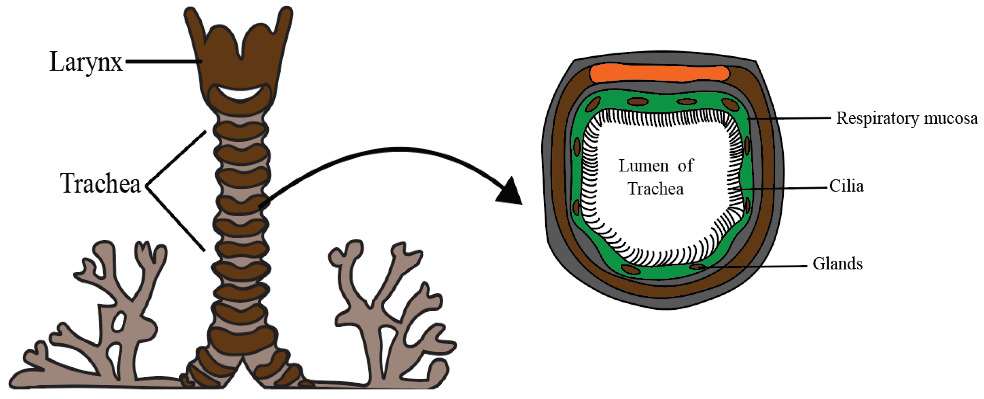
Figure 1. Anatomical and cross-sectional view of the human trachea.
Lubricants 14 00309 g001
Figure 2. Ciliary beating patterns showing (A) symplectic and (B) antiplectic metachronal waves relative to effective stroke and wave propagation direction.
Lubricants 14 00309 g002
Figure 3. (a–c) Variation in axial velocity for (a) slip parameter φ , (b) Ellis fluid parameter β and (c) thermal Grashof number G r t .
Lubricants 14 00309 g003
Figure 4. (a–c) Variation in transverse velocity for (a) Ellis fluid parameter β , (b) slip parameter φ and (c) thermal Grashof number G r t .
Lubricants 14 00309 g004
Figure 5. (a–c) Variation in axial pressure gradient for (a) Ellis fluid parameter β , (b) slip parameter φ and (c) thermal Grashof number G r t .
Lubricants 14 00309 g005
Figure 6. (a,b) Variation in temperature for (a) Prandtl number P r and (b) heat radiation factor.
Lubricants 14 00309 g006
Figure 7. (a–c) Influence of fluid parameter β on stream function ψ   w h e n   a   β =   0.2 ,   b     β = 0.3 ,   c   β = 0.4 .
Lubricants 14 00309 g007
Figure 8. (a–c) Influence of slip parameter φ on stream function ψ   w h e n   a   ϕ = 0.45 ,   b   ϕ = 0.50 ,   c   ϕ = 0.55 .
Lubricants 14 00309 g008
Figure 9. (a–c) Influence of thermal Grashof number G r t on stream function ψ   when   a   G r t = 0.1 ,   b   G r t = 0.5 ,   c   G r t = 0.9 .
Lubricants 14 00309 g009
Figure 10. Comparison of axial velocity for symplectic (dashed) and antiplectic (dotted) wave.
Lubricants 14 00309 g010
Figure 11. Relationship between shear stress τ x y and strain rate ∂ u ∂ y for the mucus in the trachea.
Lubricants 14 00309 g011
Table 1. Novelty of the present problem.
Maqbool et al. [19]
Carreau Fluid
Shaheen et al. [20]
Ellis Fluid
Ibrahim et al. [31] Bingham Plastic FluidPresent
Ellis Fluid
Free ConvectionYesNoYesYes
No Slip ConditionYesYesYesYes
Navier Slip ConditionNoNoYesYes
Exact solutionYesYesNoYes
Disclaimer/Publisher’s Note: The statements, opinions and data contained in all publications are solely those of the individual author(s) and contributor(s) and not of MDPI and/or the editor(s). MDPI and/or the editor(s) disclaim responsibility for any injury to people or property resulting from any ideas, methods, instructions or products referred to in the content.