


Abstract
The accessory gearbox of an aero-engine operates under high-speed and heavy-load conditions, where insufficient lubrication may lead to oil-film failure, increased frictional losses, and reduced transmission reliability. Therefore, understanding oil-jet injection and tooth surface oil-film spreading characteristics is essential for improving lubrication performance. In this study, a three-dimensional geometric model incorporating the meshing region and oil nozzles was established based on a typical accessory gear pair. The model employs the VOF multiphase flow approach and the standard k-ε turbulence model, coupled with dynamic mesh techniques to accurately capture the transient interactions between gear rotation and oil–air two-phase flow. Numerical simulations reveal the dynamic evolution of oil injection, impingement on the tooth surface, oil-film spreading, and transport into the meshing zone, while the effects of injection velocity and nozzle length on lubrication performance are quantitatively analyzed. Results indicate that an injection velocity of 45–55 m/s yields optimal oil-film coverage and uniformity, and a nozzle length of h = 30 mm minimizes jet energy decay and airflow interference, achieving uniform oil filling in the meshing zone. The optimal lubrication performance for accessory gears is obtained at an injection velocity of 45–55 m/s and a nozzle length of 30 mm. This study provides a reference for the design optimization of accessory gear lubrication systems.
1. Introduction
The accessory gearbox of an aero-engine serves as the core transmission unit driving critical components such as the lubricating oil pump and fuel pump, and operates under severe conditions characterized by high speed, heavy load, and high heat flux. During high-speed gear meshing, frictional heat, impact loads, and power losses can lead to oil-film rupture, local starvation, and tooth surface wear under insufficient lubrication. Compared with bath lubrication, oil-jet lubrication can deliver oil directionally at low supply rates while enhancing cooling; however, the process involves complex interactions among jet penetration through the air flow, oil-film formation, and transport into the meshing zone, exhibiting strong transient, multi-scale, and oil–air two-phase coupled characteristics.
Existing studies on high-speed gear oil-jet lubrication have primarily focused on oil-jet impingement and tooth surface wetting, lubricant transport into the meshing zone, optimization of injection parameters, and thermal-flow coupling characteristics. Fondelli et al. indicated that interactions between the oil jet and rotating tooth surfaces affect lubricant adhesion and spreading [1]. Keller et al. found that the injected lubricant undergoes impingement, spreading, breakup, and ejection, with high-speed airflow disturbances weakening jet penetration [2]. Massini et al. observed that increased gear speed reduces the effective oil reaching the tooth spaces [3]. Dai et al. analyzed the resistance torque, impingement depth, and wetted area of an oil jet on spur gears [4]. Gu et al. employed a transient multiphase model based on the VOF method and dynamic mesh techniques, revealing that oil-jet velocity has a nonlinear effect on oil-film formation and interface evolution, with moderate velocities favoring stable film formation [5]. Wang Y. et al. analyzed the effects of injection direction, position, and distance on the oil–air ratio in the meshing zone [6]. Wang et al. identified the ratio of pitch-line speed to injection velocity as a key parameter influencing gear lubrication [7]. Wang X. et al. examined how gear parameters, transmission conditions, and nozzle position affect impingement depth [8]. Liu et al. studied the effects of oil flow rate, lubricant viscosity, and gear speed on supply conditions and oil distribution [9]. Mastrone et al. combined CFD simulations with experimental validation to verify the predictive capability for oil quantity and torque variation [10,11]. Maccioni et al. indicated that existing CFD studies can analyze jet impingement, oil-film spreading, meshing-zone supply, heat dissipation, and no-load power losses, but the intrinsic relationships among jet penetration, oil-film coverage, meshing-zone filling, and tooth surface pressure remain unclear [12]. Zhang et al. investigated the effect of nozzle structure on jet diffusion angle [13]. Hu et al. showed that increasing injection velocity, reducing injection height, and adjusting nozzle deflection angle improve meshing-zone lubrication [14]. Tang et al. demonstrated that positioning the nozzle near the meshing entrance, with an appropriate deflection angle and increased velocity, enhances tooth surface oil coverage [15]. Zhang et al. examined the effects of gear speed and injection velocity on lubrication performance [16]. Zhou et al. reported that injection angle, distance, and velocity, under centrifugal force, oil splashing, and high-speed airflow, influence oil transport and exhibit an optimal parameter combination [17,18]. Xia et al. found that aligning the nozzle along the meshing airflow direction increases oil volume fraction and pressure [19]. Concli et al. suggested that axial injection is preferable, with droplet concentration and size distribution affecting oil suspension and power loss [20,21]. Li et al. indicated that gearbox housing and oil-drain design influence ventilation resistance and oil drainage [22]. Hildebrand et al. pointed out that oil wetting and circumferential velocity affect the convective heat transfer coefficient [23]. Yang et al. reported that nozzle layout alters impingement depth [24]. Dai et al. investigated the effects of injection angle, velocity, and transmission ratio on helical-gear lubrication and transient temperature fields [25]. Ouyang et al. highlighted that nozzle position significantly modifies the temperature field, with lateral placement near the tooth-width midpoint being optimal [26]. Wen et al. observed that increased gear pitch-line speed aggravates jet breakup and tooth surface temperature rise, while optimizing oil-pipe diameter, bends, and nozzle aspect ratio improves oil distribution and transmission efficiency [27,28]. Qiao et al. and Zhang et al. indicated that increasing injection velocity while accounting for lubricant properties enhances tooth surface heat transfer and improves predictions of oil–air two-phase flow [29,30].
Although previous studies have provided valuable insights into high-speed gear oil-jet lubrication, several limitations remain. Most investigations have focused on conventional transmission gears, while lubrication characteristics of aero-engine accessory gears under specific operating conditions remain insufficiently understood. Moreover, the coupled influence mechanism of injection parameters, jet impingement behavior, tooth surface wetting, and lubricant transport into the meshing zone requires further investigation.
Compared with experimental approaches, numerical simulation provides an effective method for investigating the transient oil–air two-phase flow characteristics inside aero-engine accessory gearboxes. The CFD approach allows detailed visualization of oil-jet penetration, interface evolution, and tooth surface wetting under different operating conditions, which is difficult to achieve experimentally due to the high-speed rotating environment and limited accessibility of the internal flow field. Based on this, the present study constructs a numerical model of the accessory gear meshing region with oil nozzles, analyzing the effects of injection velocity and nozzle length on oil-film formation, lubricant distribution in the meshing zone, and tooth surface pressure, providing a basis for optimizing accessory gear lubrication systems.
2. Theoretical Basis
This study involves oil–air two-phase flow under high-speed rotation, characterized by complex interfacial evolution and highly turbulent flow features. Therefore, the turbulence model and the VOF model are employed for numerical solutions.
2.1. Turbulence Model
Considering the characteristics of high-speed jet flow, strong shear flow, and oil–air mixing in the gear oil-jet lubrication flow field, the standard k-ε turbulence model is adopted to close the Reynolds-averaged Navier–Stokes (RANS) equations. The standard k-ε turbulence model was selected considering the characteristics of the present oil-jet lubrication process. The dominant flow phenomena include turbulent jet development, oil–air mixing, and lubricant transport under rotating gear conditions. Compared with models optimized for near-wall flow prediction, such as the SST k-ω model with curvature correction, the standard k-ε model provides better computational efficiency and robust convergence for transient multiphase simulations involving dynamic mesh motion. Since this study mainly focuses on macroscopic oil distribution and tooth surface wetting characteristics rather than detailed boundary-layer separation phenomena, the standard k-ε model is considered appropriate for the current investigation. Its core concept is to calculate the turbulent eddy viscosity μt by solving the transport equations of turbulent kinetic energy k and its dissipation rate ε:
where ρ denotes the fluid density and Cμ is an empirical constant, generally taken as 0.09. The transport equations for turbulent kinetic energy k and its dissipation rate ε are expressed as follows [15]:
where Gk is the turbulence production term induced by the mean velocity gradient. The model constants are C1ε = 1.44, C2ε = 1.92, σk = 1.0, and σε = 1.3.
2.2. VOF Model
To accurately track the complex and dynamic free interface between lubricating oil and air, the Volume of Fluid (VOF) model is adopted in this study. The VOF model tracks the interface between different phases by solving an additional volume fraction transport equation. Defining α2 as the volume fraction of the lubricating-oil phase, its transport equation can be expressed as:
When α2 = 1, the computational cell is fully occupied by lubricating oil; when α2 = 0, the cell is filled with air; and when 0 < α2 < 1, the cell contains the oil–air interface. The density ρ and dynamic viscosity μ of the mixture are obtained by volume-fraction-weighted averaging of the properties of each phase:
The effect of surface tension is considered in the momentum equation and implemented by introducing the source term Fs:
3. Numerical Model and Computational Method
3.1. Geometric Model and Computational Domain
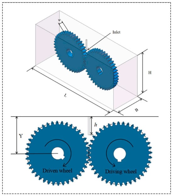
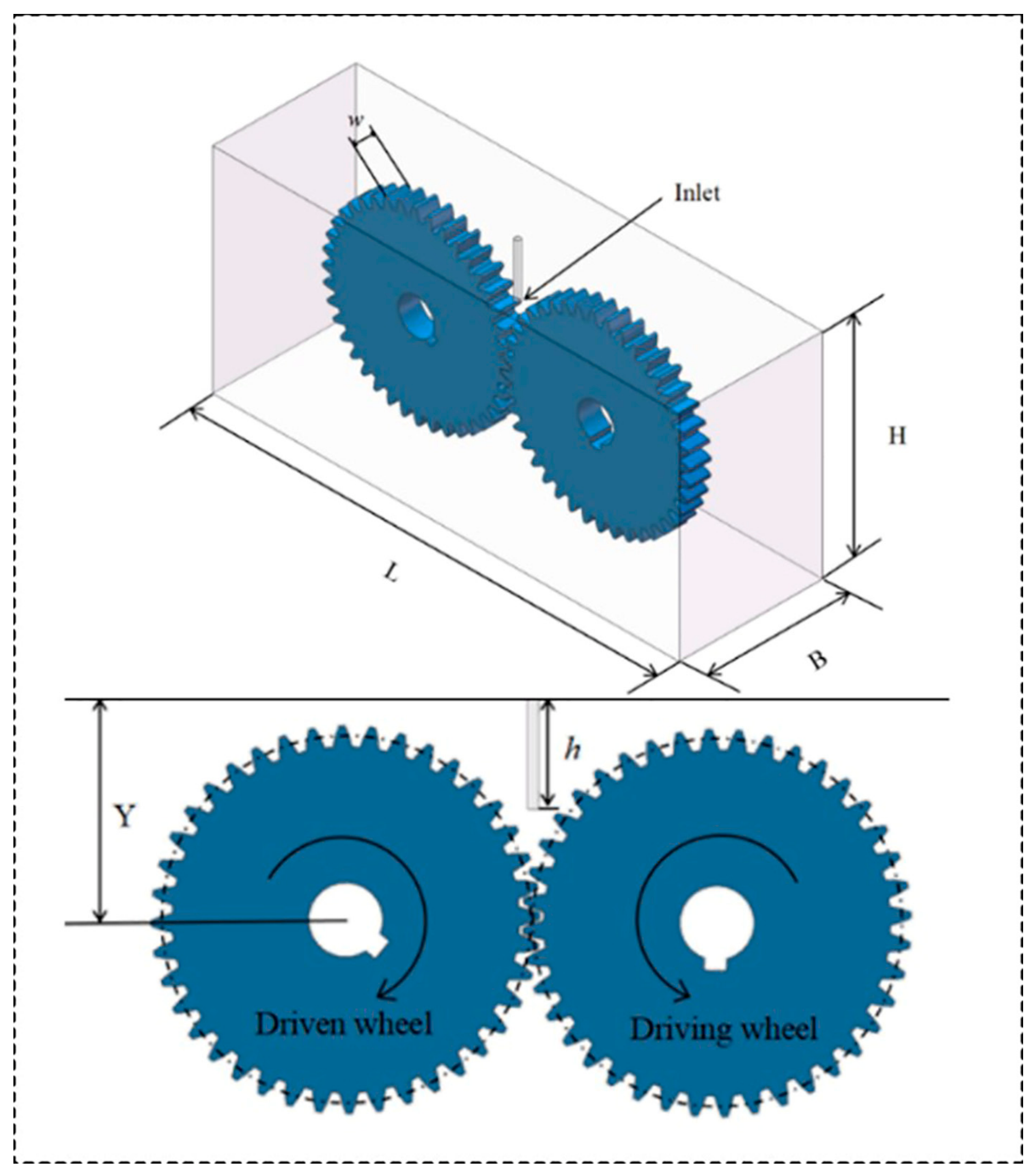
The geometric model used in this study is simplified from a typical aero-engine accessory gearbox, consisting of a driving gear, a driven gear, a gearbox housing, and an oil nozzle. The gears are spur gears with a module of 2.5 mm, a tooth number of 40, and a tooth width of 12 mm. The nozzle axis and the gear meshing point are arranged in the same plane. The computational domain is defined as the internal fluid region between the gearbox housing and the gears. The geometric model is shown in Figure 1, and the key geometric parameters are listed in Table 1.
Figure 1.
Geometric model.
Table 1.
Main geometric parameters of the computational model.
3.2. Mesh Generation and Independence Analysis
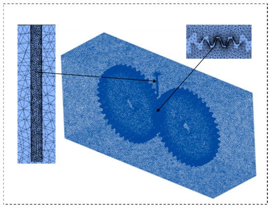
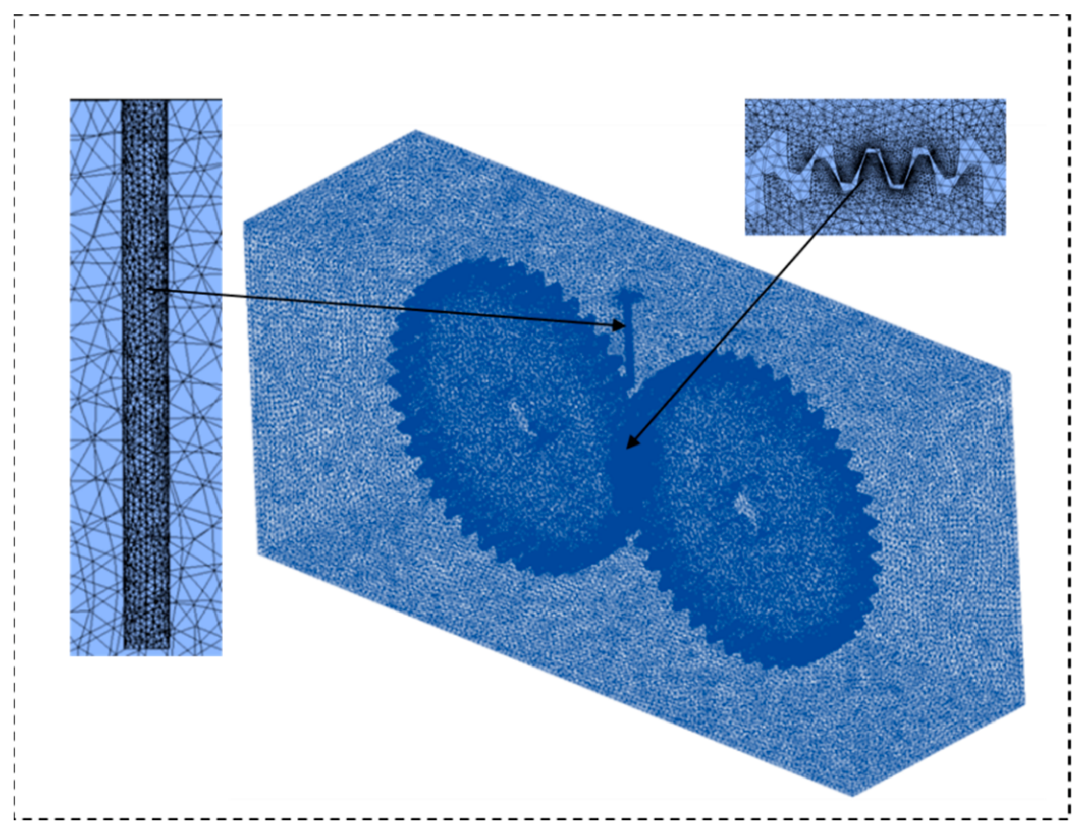
The computational domain was discretized using an unstructured tetrahedral mesh. Considering the strong interaction between the oil jet and rotating gears, local mesh refinement was performed around the nozzle outlet, gear meshing region, and tooth surface area. Prism layers were additionally generated near solid walls to improve the prediction of near-wall flow characteristics. The final mesh contained approximately 2.45 million cells, and the mesh quality was maintained above 0.8, ensuring numerical stability and accuracy. Figure 2 shows the mesh model for oil-jet lubrication of the accessory gears.
Figure 2.
Mesh model for oil-jet lubrication of the accessory gears.
A mesh independence study was conducted to evaluate the influence of mesh resolution on numerical accuracy in Table 2. Three mesh densities were investigated. The predicted maximum tooth surface impact pressure showed only a small variation when the mesh was refined from medium to fine resolution, with a relative difference below 2%. Therefore, the medium mesh containing approximately 2.45 million cells was adopted for subsequent simulations, providing a reasonable balance between computational accuracy and efficiency.
Table 2.
Mesh independence analysis of the computational model.
3.3. Dynamic Mesh and Boundary Conditions
To simulate the fixed-axis rotational motion of the gears, the dynamic mesh technique was adopted. The angular velocities of the driving gear and driven gear were defined as +30 rad/s and −30 rad/s, respectively, using user-defined functions (UDFs). Spring-based smoothing and local remeshing methods were employed to accommodate mesh deformation induced by gear rotation, thereby ensuring mesh quality and numerical stability.
The boundary conditions were specified as follows. The oil nozzle inlet was defined as a velocity inlet, with an injection velocity of v = 45 m/s and an oil-phase volume fraction of 1. The bottom surface of the housing was set as a pressure outlet, with a gauge pressure of 0 Pa. All walls were treated as no-slip and adiabatic boundaries, and the wall contact angle was set to 90°. The physical properties of air were obtained from the standard material database in ANSYS Fluent 2024 R1. The density and dynamic viscosity of the lubricating oil correspond to the measured properties of 4106 aviation lubricating oil under the operating conditions considered in this study. The lubricating oil and air was treated as an incompressible Newtonian fluid with constant viscosity. The physical properties of lubricating oil and air are listed in Table 3.
Table 3.
Physical properties of lubricating oil and air.
3.4. Solution Strategy
A pressure-based solver was employed, and the SIMPLE algorithm was used for pressure–velocity coupling because of its robust convergence characteristics in transient multiphase flow simulations with dynamic mesh motion. The pressure term was discretized using the PRESTO! scheme, while the momentum equations were discretized using a second-order upwind scheme. The volume fraction equation was solved using the Compressive scheme to sharpen the phase interface, and the turbulence equations were discretized using a first-order upwind scheme to ensure numerical convergence. For the transient calculation, the time step was set to 5 × 10⁻⁵ s, with 20 iterations performed within each time step. The total physical time was 0.2 s, corresponding to approximately one revolution of the gears.
4. Results and Discussion
4.1. Influence of Injection Velocity on Tooth Surface Lubrication
To investigate the effect of injection velocity, simulations were conducted with a nozzle length of h = 30 mm, considering injection velocities of 35, 45, 55, and 65 m/s for the accessory gears, analyzing the oil-jet behavior and tooth surface oil-film spreading.
4.1.1. Distribution of Oil Phase Volume Fraction on the Tooth Surface Under Different Injection Velocities
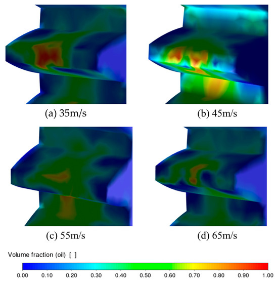
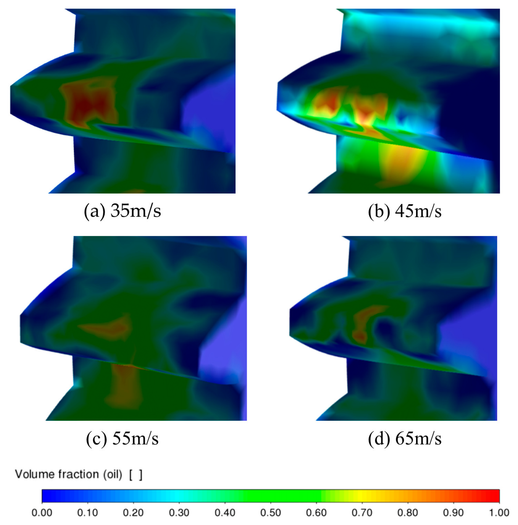
Figure 3 shows the distribution of oil phase volume fraction on the tooth surfaces under different injection velocities with a nozzle length of h = 30 mm. It can be seen that the injection velocity significantly affects both the spreading range and uniformity of oil on the tooth surfaces and in the meshing zone. At v = 35 m/s, the oil penetrates the gear meshing region and forms a high oil-phase volume fraction region near the jet impingement area, but the overall coverage is relatively limited. The oil is primarily concentrated in localized regions, indicating that the jet momentum is insufficient to achieve uniform spreading across the tooth surface. Increasing the velocity to 45 m/s significantly expands the high-concentration region. The oil effectively reaches the meshing zone and further spreads along the tooth surfaces and near the tooth root, forming a relatively continuous lubrication layer. This indicates improved jet penetration and adhesion at this velocity. At v = 55 m/s, the oil coverage remains extensive, but high-concentration areas begin to disperse. Locally, oil is redistributed by gear rotation, shear, and centrifugal effects, reducing the concentration uniformity on the tooth surface. At v = 65 m/s, oil distribution becomes more uneven. High-volume-fraction regions are mainly concentrated near localized impingement zones, and the continuous coverage weakens. This indicates that excessively high injection velocity can lead to oil rebound, splashing, and breakup, preventing stable adhesion on the tooth surface. The underlying mechanism is that increasing injection velocity raises the kinetic energy and momentum of the jet, which helps overcome airflow disturbances induced by high-speed gear rotation and facilitates oil penetration into the meshing zone. However, if the velocity is too high, excessive impingement causes splashing and secondary breakup of the oil, combined with shear, entrainment, and centrifugal effects due to gear rotation, reducing stable adhesion on the tooth surface. Conversely, too low a velocity results in insufficient supply, while excessive velocity weakens the continuity and stability of oil spreading.
Figure 3.
Distribution of oil phase volume fraction on the tooth surface at different injection velocities with a nozzle length of h = 30 mm.
In summary, an injection velocity of 45 m/s provides a relatively wide and continuous oil-film coverage, achieving good lubrication performance. At v = 55 m/s, the uniformity slightly decreases, and at 65 m/s, oil splashing and local concentration are evident. Overall, moderately increasing the injection velocity improves tooth surface supply, but excessive velocity should be avoided to prevent reduced oil utilization.
4.1.2. Tooth Surface Static Pressure Distribution Under Different Injection Velocities
Jet impingement plays a critical role in determining the initial distribution of lubricant on the tooth surface. A moderate impingement intensity enhances momentum transfer from the oil jet to the tooth surface, allowing the lubricant to overcome airflow disturbance and establish effective wetting. However, excessive impact intensity may increase oil rebound and secondary breakup, which reduces stable adhesion and deteriorates lubrication uniformity.
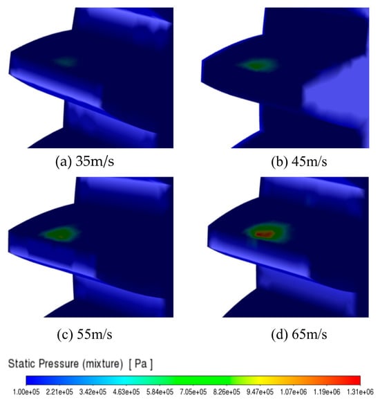
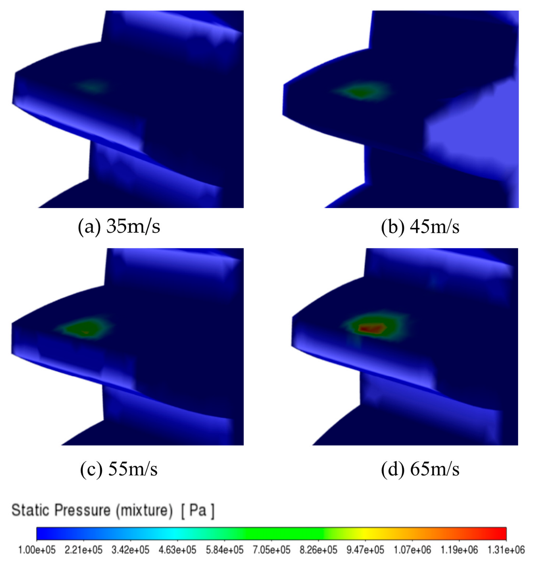
Figure 4 shows the tooth surface static pressure distribution under different injection velocities with a nozzle length of h = 30 mm. It can be observed that, in all cases, the high-pressure regions are primarily concentrated in localized areas where the oil jet directly impinges on the tooth surface, while the surrounding areas exhibit relatively low static pressure. As the injection velocity increases from 35 m/s to 65 m/s, the high-pressure regions gradually expand, and the pressure peaks rise significantly. In Figure 4a, at v = 35 m/s, only weak localized high-pressure areas appear, indicating that the jet impingement is relatively limited. Figure 4b,c show that when the velocity is increased to 45 m/s and 55 m/s, the jet momentum strengthens, resulting in significantly higher static pressure in the impingement region and further expansion of the high-pressure zones. At v = 65 m/s, more pronounced high-pressure concentration occurs in localized areas, indicating that the impact load on the tooth surfaces is further intensified by the high-speed jet. This behavior is attributed to the increase in kinetic energy and momentum of the oil jet at higher velocities. During impingement, stronger momentum exchange occurs, converting dynamic pressure into static pressure more effectively, thus increasing the local impact pressure on the tooth surface. While higher injection velocities enhance the jet’s ability to penetrate the surrounding airflow and improve oil delivery to the meshing zone and tooth surface adhesion, excessively high impact pressures can also lead to oil rebound, splashing, and increased risks of localized erosion and fatigue damage.
Figure 4.
Static pressure distribution on the tooth surface at different injection velocities with a nozzle length of h = 30 mm.
Combining these results with the previously discussed oil phase distribution, it can be concluded that an injection velocity within the 45–55 m/s range provides effective oil delivery and good lubrication coverage while avoiding adverse effects from excessive impact load on the tooth surfaces.
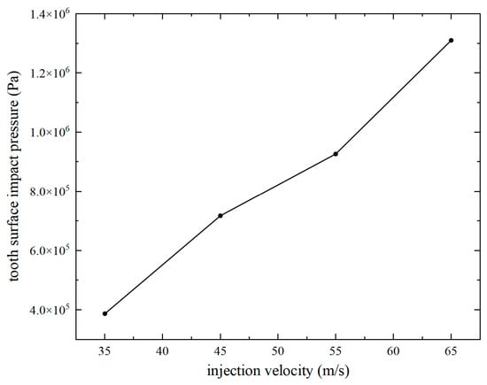
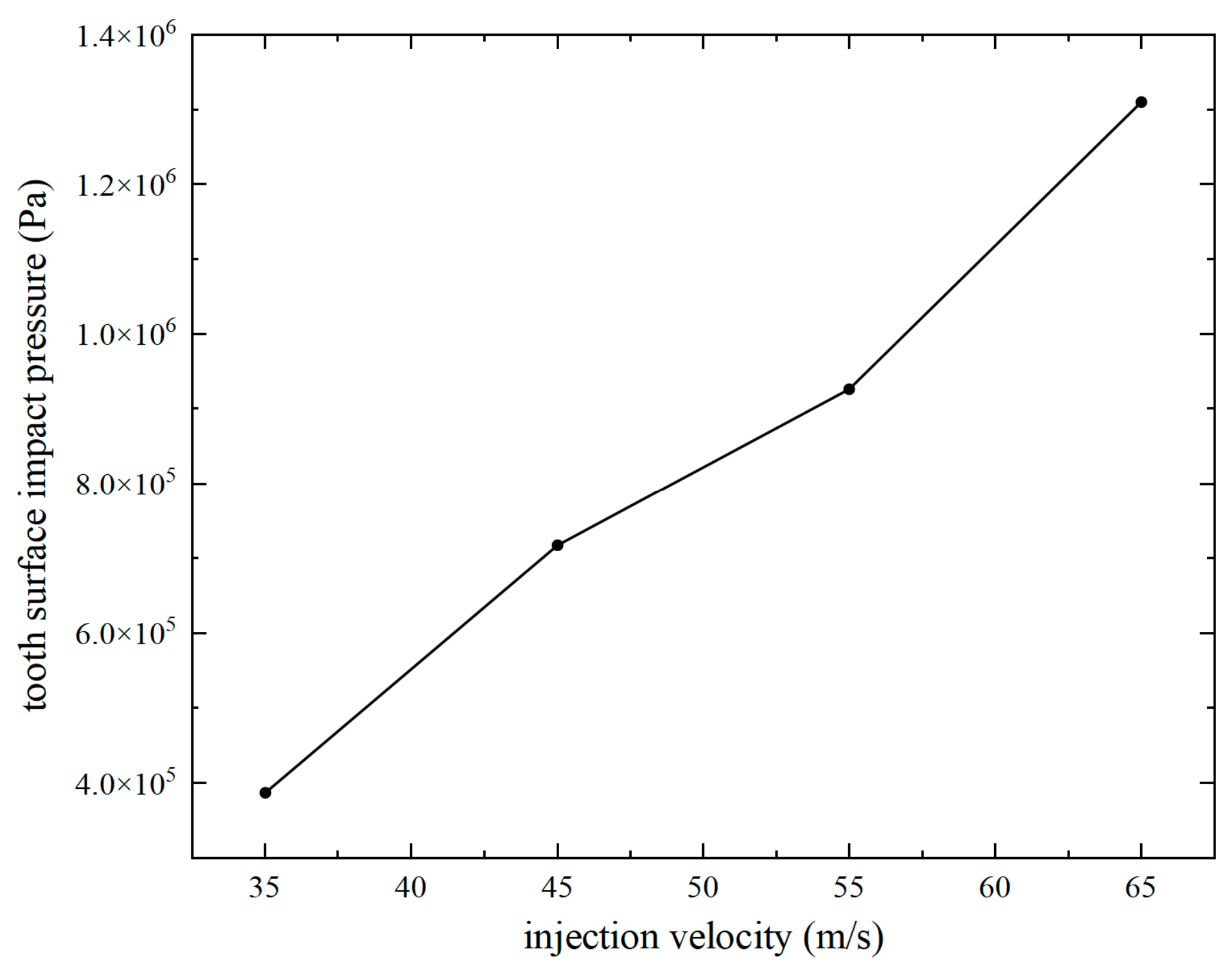
Figure 5 shows the maximum tooth surface impact pressure under different injection velocities with a nozzle length of h = 30 mm. It can be observed that the maximum impact pressure exhibits a nonlinear increase as the injection velocity rises. At v = 35 m/s, the maximum impact pressure is approximately 3.87 × 10⁵ Pa. Increasing the velocity to 45 m/s and 55 m/s raises the maximum impact pressure to 7.17 × 10⁵ Pa and 9.26 × 10⁵ Pa, respectively. When the velocity further increases to 65 m/s, the maximum impact pressure reaches 1.31 × 10⁶ Pa, indicating that higher injection velocity significantly enhances the jet impingement on the tooth surfaces. This behavior is attributed to the increased kinetic energy and momentum of the oil jet at higher velocities, which intensifies the momentum exchange during impingement and promotes the conversion of dynamic pressure into static pressure, thereby raising the local impact pressure. The nonlinear increase in maximum impact pressure can be explained by the nonlinear growth of jet kinetic energy and momentum with injection velocity. According to the relationship between dynamic pressure and velocity, the jet impact pressure is strongly related to the square of the injection velocity. Therefore, a moderate increase in injection velocity can result in a more significant enhancement of jet momentum and energy conversion during impingement. In addition, as the injection velocity increases, the oil jet maintains better coherence before reaching the tooth surface, reducing dispersion caused by surrounding airflow and increasing the local pressure concentration at the impact region. These combined effects lead to a nonlinear increase rather than a linear variation in the maximum impact pressure. While higher velocities improve the jet’s ability to penetrate the surrounding air layer and enhance lubrication coverage in the meshing zone, excessive impact pressure can lead to oil rebound and splashing, reducing the stability of oil adhesion and potentially increasing the risk of localized erosion and fatigue damage, while also affecting the stability of the oil supply system.
Figure 5.
Variation in tooth surface impact pressure with injection velocity.
Combining these results with the oil-phase distribution shown in Figure 4, it can be concluded that an injection velocity within the 45–55 m/s range ensures effective oil spreading and good lubrication coverage while keeping the impact load within a relatively reasonable range.
These findings are generally consistent with previous investigations on high-speed gear oil-jet lubrication [15,17]. Previous studies have reported that increasing injection velocity enhances jet momentum and improves the penetration capability of lubricant into the meshing region under the disturbance of rotating airflow. Similar behavior is observed in the present study, indicating that sufficient jet momentum is essential for maintaining effective lubricant transport and tooth surface wetting. However, unlike previous studies mainly focusing on conventional industrial gears, the present work further considers the complex oil–air interaction and transient oil-film spreading characteristics of aero-engine accessory gears.
4.2. Influence of Nozzle Length on Tooth Surface Lubrication Characteristics
In this section, the oil-jet injection and tooth surface oil-film spreading processes of the accessory gears were simulated at an injection velocity of v = 35 m/s, with the nozzle length h varied as 28 mm, 30 mm, and 32 mm to evaluate its influence on jet development and oil distribution.
4.2.1. Distribution of Oil Phase Volume Fraction on the Tooth Surface Under Different Nozzle Lengths
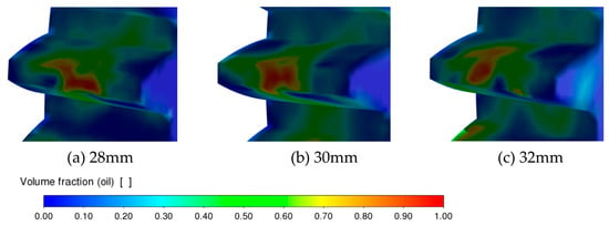
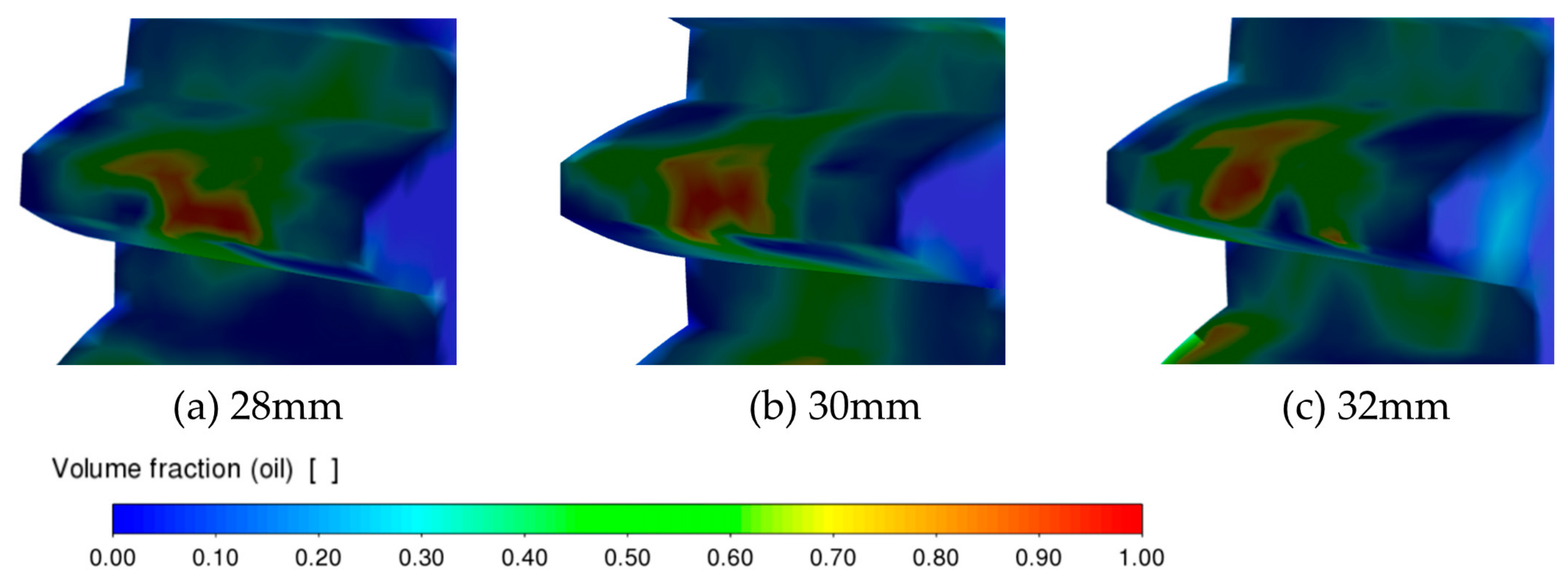
Figure 6 shows the distribution of oil phase volume fraction on the tooth surface under different nozzle lengths. It can be observed that the nozzle length has a significant influence on oil spreading over the tooth surface and within the meshing zone. When the nozzle length is h = 32 mm, the nozzle is relatively close to the tooth surface, and the jet directly impinges on the tooth surface before it is fully developed. Although a high oil-phase volume fraction appears in local regions, the strong impingement effect and airflow disturbance induced by gear rotation promote oil splashing and deviation, resulting in discontinuous oil distribution on the tooth surface. Consequently, the oil is mainly concentrated in localized high-concentration regions. When the nozzle length is h = 30 mm, the jet has an appropriate development distance before reaching the tooth surface. Under this condition, the jet can maintain sufficient momentum to penetrate the airflow field around the gears while avoiding oil rebound caused by excessive impingement. Therefore, the oil can enter the meshing zone more stably and form a relatively wide and uniformly distributed lubrication layer along the tooth surface, indicating improved oil supply performance. When the nozzle length is h = 28 mm, the jet propagation path becomes longer, and the oil is more strongly affected by air resistance and rotational airflow disturbances before reaching the tooth surface. The resulting momentum attenuation reduces the amount of effective oil entering the meshing zone, decreases the local oil-phase volume fraction, and narrows the lubrication coverage on the tooth surface.
Figure 6.
Distribution of oil phase volume fraction on the tooth surface under different nozzle lengths at an injection velocity of v = 35 m/s.
In summary, under a fixed injection velocity, an excessively large nozzle length leads to overly strong jet impingement and pronounced oil splashing, whereas an excessively small nozzle length causes jet momentum loss and insufficient oil supply. By comparison, a nozzle length of h = 30 mm achieves a better balance between jet penetration and stable oil adhesion, which is conducive to forming a more continuous and uniform oil film on the tooth surface.
4.2.2. Tooth Surface Static Pressure Distribution Under Different Nozzle Lengths
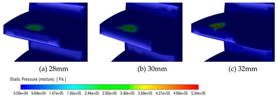
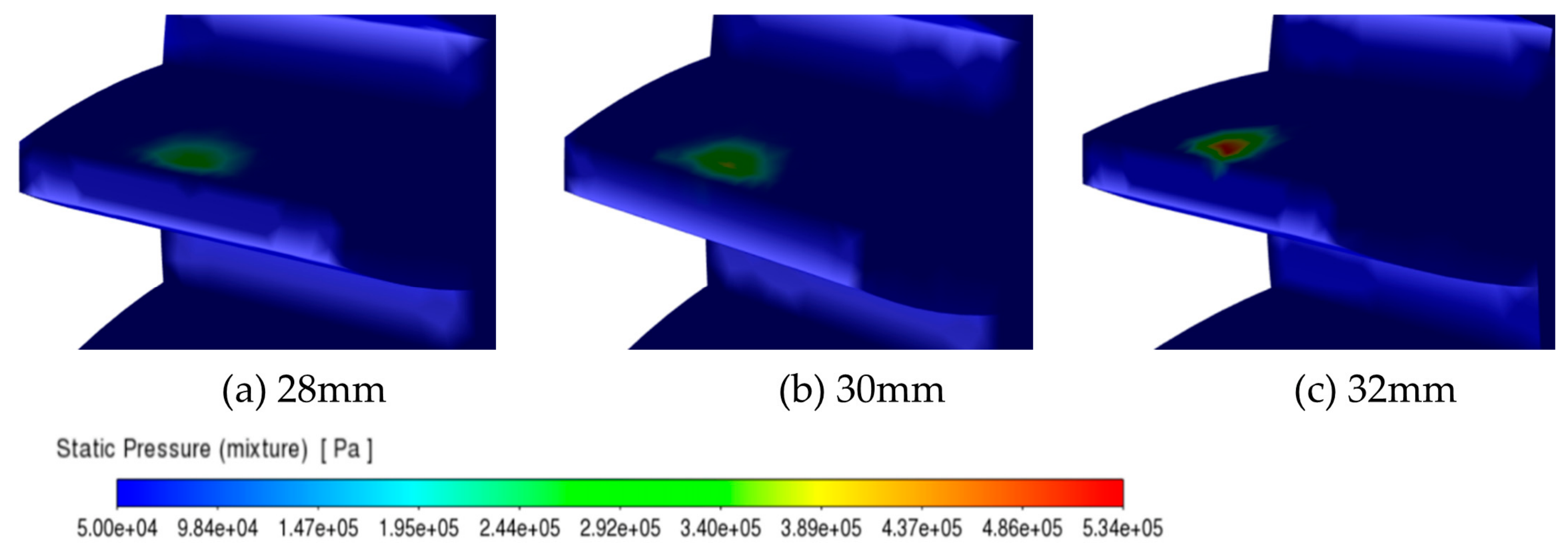
Figure 7 shows the tooth surface static pressure distribution under different nozzle lengths at an injection velocity of v = 35 m/s. It can be seen that, for all three nozzle lengths, the high-pressure regions are concentrated in the localized areas where the oil jet directly impinges on the tooth surfaces, while most of the surrounding tooth surfaces remain at relatively low static pressure, indicating that the jet exerts a strongly localized pressure effect. As the nozzle length increases from 28 mm to 32 mm, the high-pressure regions become more pronounced, and the local pressure peaks increase significantly. In Figure 7a, at h = 28 mm, the high-pressure area is relatively small, and the pressure concentration is weak. Figure 7b shows that when the nozzle length is h = 30 mm, the static pressure in the impingement region increases. Figure 7c indicates that at h = 32 mm, a more pronounced high-pressure concentration appears on the tooth surface, showing that the jet produces a stronger local impact upon reaching the tooth surface. This phenomenon is mainly attributed to the influence of nozzle length on the jet development and energy distribution before reaching the tooth surface. Properly increasing the nozzle length enhances the directionality and concentration of the jet, resulting in a more pronounced conversion of dynamic pressure into static pressure in the localized impingement zone, thereby increasing the local static pressure on the tooth surface.
Figure 7.
Static pressure distribution on the tooth surface under different nozzle lengths at an injection velocity of v = 35 m/s.
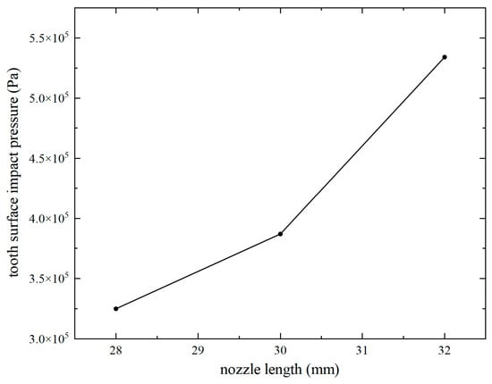
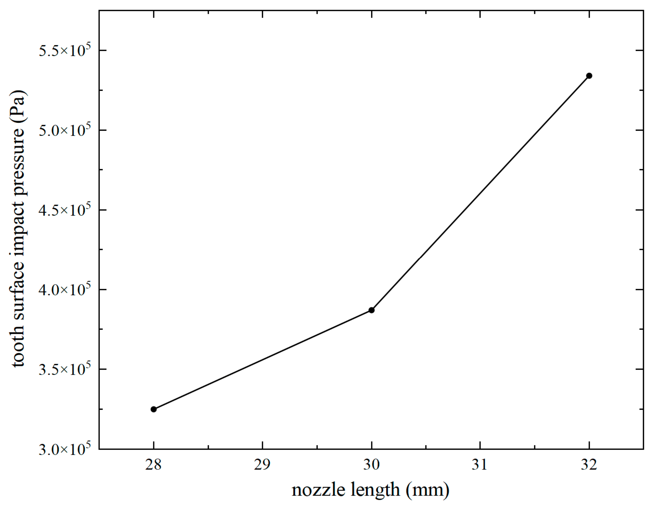
Figure 8 shows the variation in the tooth surface impact pressure with nozzle length. It can be observed that the impact pressure increases monotonically as the nozzle length increases from 28 mm to 32 mm. When the nozzle length is h = 28 mm, the impact pressure is approximately 3.25 × 10⁵ Pa. As the nozzle length increases to h = 30 mm, the impact pressure rises to approximately 3.87 × 10⁵ Pa. When the nozzle length further increases to h = 32 mm, the impact pressure reaches approximately 5.34 × 10⁵ Pa, showing the most pronounced increase. This result indicates that, under the present computational conditions, increasing the nozzle length enhances the localized impact load exerted by the oil jet on the tooth surface. However, higher impact pressure does not necessarily correspond to better lubrication performance. Combined with the oil phase volume fraction distribution on the tooth surface, the results show that at h = 32 mm, although the oil jet produces a relatively high local impact pressure, the stable spreading of the oil on the tooth surface deteriorates, and local concentration, splashing, or insufficient coverage may occur. By contrast, at h = 30 mm, the jet impingement intensity is moderate, allowing the oil to enter the meshing zone more stably and form a relatively continuous and uniform lubrication layer.
Figure 8.
Variation in maximum tooth surface impact pressure with nozzle length.
Therefore, a nozzle length of h = 30 mm achieves a better balance between impact load and oil-film spreading performance and is identified as the preferable nozzle length under the present operating condition.
4.3. Influence of Injection Velocity and Nozzle Length on Oil Distribution in the Gear Meshing Zone
4.3.1. Influence of Injection Velocity on Oil Distribution in the Gear Meshing Zone
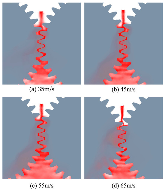
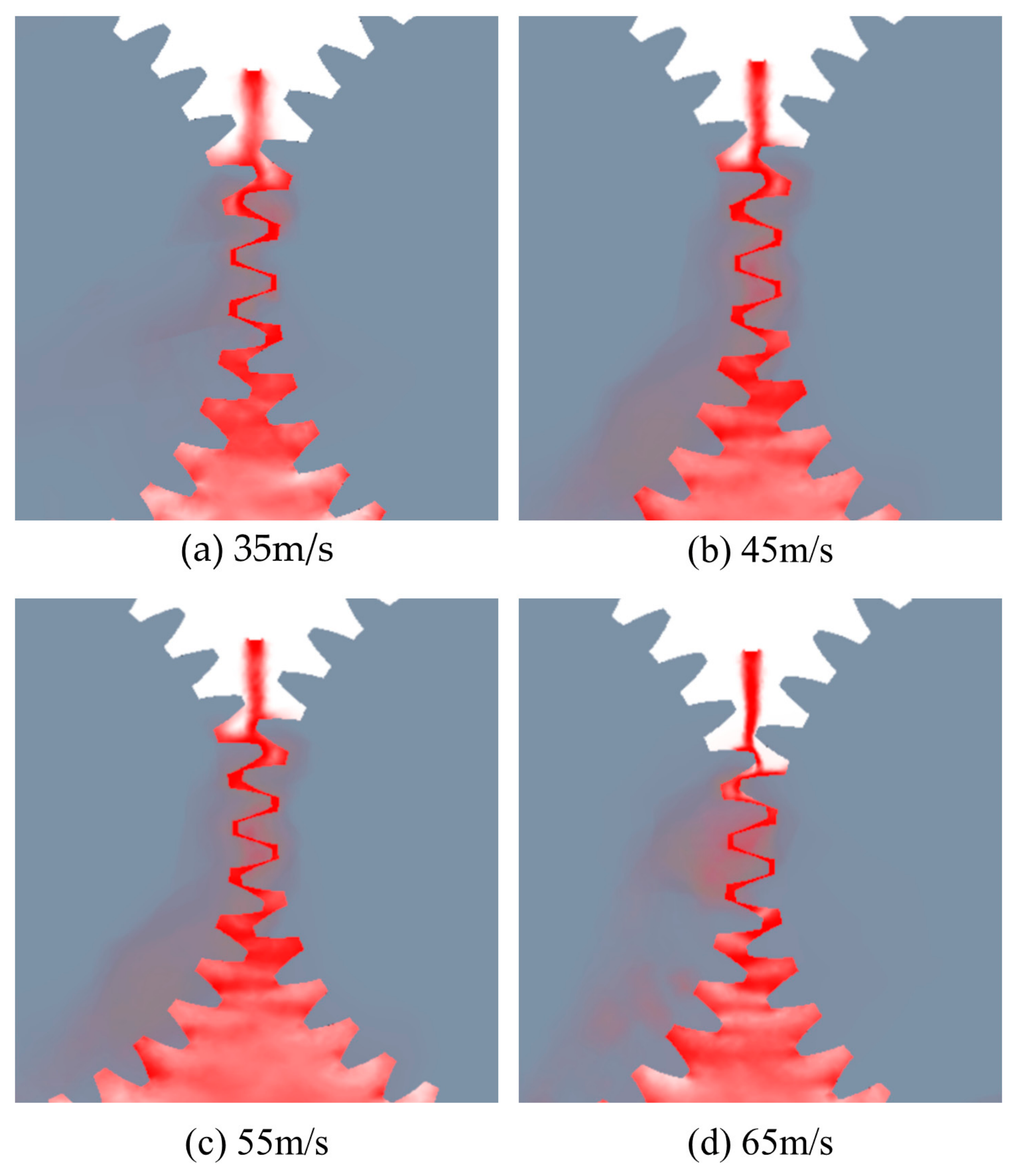
With the nozzle length fixed at h = 30 mm, the oil distribution in the gear meshing zone was calculated at injection velocities of 35 m/s, 45 m/s, 55 m/s, and 65 m/s. As shown in Figure 9, under different injection velocities, the oil distribution in the meshing zone exhibits distinct characteristics of jet impingement, entrainment by gear rotation, and subsequent diffusion. Figure 9a shows that when the injection velocity is v = 35 m/s, the oil is mainly concentrated in the region from the nozzle outlet to the vicinity of the meshing zone. The jet remains relatively continuous, but its diffusion toward both sides of the tooth surface and the tooth-root region is limited. As shown in Figure 9b,c, when the injection velocity increases to 45 m/s and 55 m/s, the amount of oil entering the meshing zone increases significantly. The oil coverage in the tooth contact region and near the tooth root expands, and a more pronounced oil-enriched region forms around the gear meshing band. When the injection velocity is further increased to 65 m/s, the oil can still effectively reach the meshing zone. However, under the combined effects of high-speed jet impingement and gear-rotation-induced disturbance, local oil distribution exhibits deviation and splashing, and the oil concentration near the meshing zone does not continue to increase significantly. This behavior can be explained by the increase in jet momentum with injection velocity. A higher jet momentum enhances the ability of the oil to overcome surrounding airflow disturbances and enter the tooth meshing zone, thereby increasing the oil coverage near the tooth surface. Meanwhile, high-speed gear rotation induces shear, entrainment, and centrifugal oil fling-off, causing part of the oil to diffuse along the tooth surface and tooth-root region. When the injection velocity becomes excessively high, the interaction between the oil jet and the rotating gears becomes more intense, and the oil is more likely to rebound, break up, and disperse, preventing part of the oil from stably adhering to the meshing-zone surface.
Figure 9.
Oil distribution in the gear meshing zone at different injection velocities with a nozzle length of h = 30 mm.
Therefore, an appropriate increase in injection velocity is beneficial for improving oil supply to the gear meshing zone. However, excessively high injection velocity may reduce oil utilization efficiency and affect the uniformity of oil distribution in the meshing zone.
4.3.2. Influence of Nozzle Length on Oil Distribution in the Gear Meshing Zone
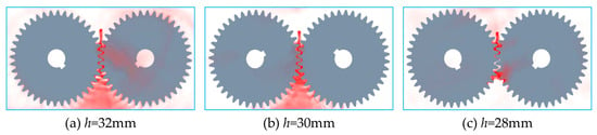
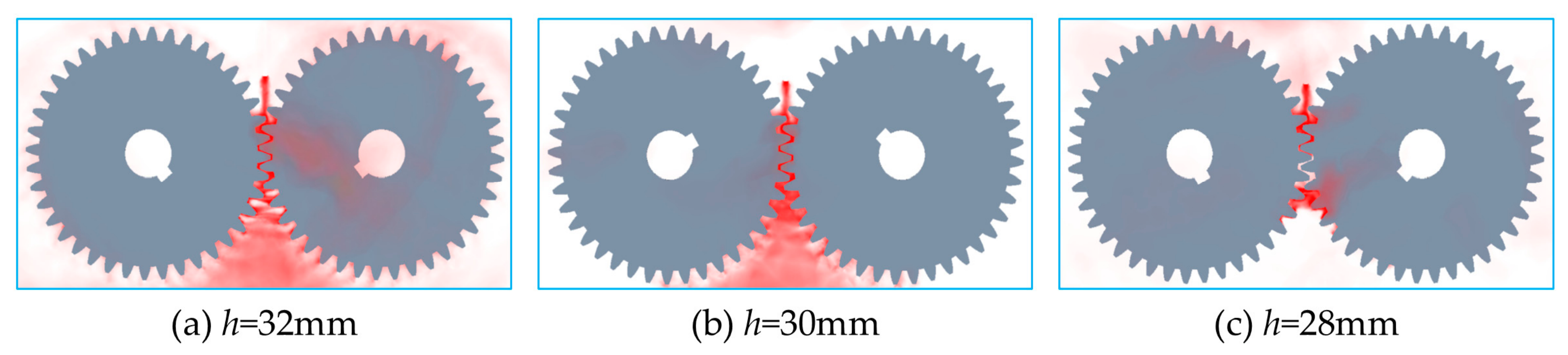
Under the condition of an injection velocity of v = 35 m/s, the oil distribution in the gear meshing zone was calculated for nozzle lengths of 28 mm, 30 mm, and 32 mm. As shown in Figure 10, at v = 35 m/s, the oil distribution in the gear meshing zone changes significantly as the nozzle length decreases from 32 mm to 28 mm. When the nozzle length is h = 32 mm, Figure 10a shows that the nozzle outlet is relatively close to the meshing zone, allowing the oil jet to enter the meshing region of the two gears more directly. A relatively pronounced oil-enriched region is formed near the meshing zone, and a certain range of oil coverage appears on both the tooth surface and the tooth-root region. However, due to the relatively short injection distance, the jet impingement effect becomes stronger, causing part of the oil to diffuse and splash near the meshing zone. When the nozzle length is h = 30 mm, Figure 10b shows that the oil jet can still reach the meshing zone stably. The oil is mainly concentrated near the meshing line of the two gears, with a relatively concentrated distribution, resulting in favorable lubrication coverage on the tooth surface. When the nozzle length is h = 28 mm, Figure 10c shows that before reaching the meshing zone, the oil is more significantly affected by air resistance and rotational airflow disturbances around the gears. As a result, the continuity of the jet weakens, the amount of oil entering the meshing zone decreases, the distribution range of the oil near the meshing zone becomes smaller, and part of the oil exhibits deviation and dispersion.
Figure 10.
Oil distribution in the gear meshing zone under different nozzle lengths at an injection velocity of v = 35 m/s.
The underlying reason is that when the nozzle length is relatively small, the jet experiences less momentum loss, allowing the oil to enter the tooth meshing zone rapidly. However, excessively short-distance injection enhances the impingement effect between the jet and the gear surface, making the oil more likely to be scattered by gear rotation. As the nozzle length is appropriately increased, the jet has a certain development distance before reaching the meshing zone, enabling the oil to enter the meshing zone more smoothly and thereby improving the lubrication distribution on the tooth surface. By contrast, when the nozzle length becomes excessively large, the jet undergoes more severe momentum attenuation during propagation and is more strongly subjected to entrainment and deflection by the surrounding airflow field, leading to a reduction in the effective oil reaching the meshing zone.
In summary, under the condition of v = 35 m/s, nozzle length has an important influence on lubrication performance in the gear meshing zone. Either an excessively large or an excessively small nozzle length is unfavorable for oil spreading in the meshing zone, thereby affecting the lubrication performance.
5. Conclusions
In this study, a three-dimensional transient numerical model for oil-jet lubrication of aero-engine accessory gears was established based on the CFD method, incorporating the VOF multiphase flow model and dynamic mesh technique. The effects of injection velocity and nozzle length on oil-jet injection and tooth surface oil-film spreading were investigated. The main conclusions are summarized as follows:
(1) An optimal range of injection velocity exists for accessory gear oil-jet lubrication. When the injection velocity is within the range of 45–55 m/s, the lubricating oil film spreads more uniformly and the lubrication performance is optimized. At an injection velocity of 35 m/s, the jet kinetic energy is insufficient to overcome the surrounding airflow barrier, resulting in inadequate oil-film spreading on the tooth surface. When the injection velocity reaches 65 m/s, severe oil splashing and atomization occur, making it difficult to form a stable and continuous oil film. Only within the range of 45–55 m/s can the oil jet achieve effective penetration and uniform spreading. Under this condition, the tooth surface impact pressure is maintained between 7.17 × 10⁵ Pa and 9.26 × 10⁵ Pa, corresponding to a favorable lubrication state.
(2) The preferred nozzle length is h = 30 mm. When the nozzle length is h = 28 mm, the jet experiences greater momentum attenuation and the oil distribution becomes more dispersed before reaching the meshing zone. When the nozzle length is h = 32 mm, strong local impingement induces pronounced splashing and rebound, leading to non-uniform oil coverage and potential lubrication-deficient regions. At h = 30 mm, a balance is achieved between jet energy retention and airflow disturbance, and the coverage range and uniformity of the oil film reach their optimal state.
(3) The best lubrication performance is obtained when the injection velocity is within 45–55 m/s and the nozzle length is h = 30 mm. Under this condition, the tooth surface oil film is relatively complete, and the oil distribution in the meshing zone is continuous and uniform. An effective hydrodynamic oil film can be formed, which helps reduce friction and wear while avoiding excessive impact load and energy consumption.
The simulation method established in this study and the quantitative conclusions obtained provide a reliable theoretical basis and technical support for the refined design and parameter optimization of oil-jet lubrication systems for aero-engine accessory gears.
Although the present study provides insight into the oil-jet injection and tooth surface oil-film spreading characteristics of aero-engine accessory gears, several limitations should be noted. First, the current model mainly focuses on the hydrodynamic behavior of oil–air two-phase flow, while thermal effects and temperature-dependent lubricant properties are not considered. Second, the lubricant is treated as a Newtonian fluid, and possible effects of lubricant additives and complex rheological behavior require further investigation. Third, although the numerical methodology has been compared with previous studies, further experimental validation under realistic aero-engine operating conditions is required. Future work will consider thermo-fluid coupling effects and experimental verification to further improve the predictive capability of the model.
Author Contributions
Conceptualization, J.L. and F.W.; methodology, J.L.; software, J.L.; formal analysis, F.W.; investigation, F.W.; resources, Z.G.; data curation, Z.G.; writing—original draft preparation, J.L.; writing—review and editing, M.H. and Z.G.; visualization, M.H.; supervision, F.W.; project administration, F.W. All authors have read and agreed to the published version of the manuscript.
Funding
This research received no external funding.
Data Availability Statement
The data that support the findings of this study are available upon reasonable request from the corresponding author.
Conflicts of Interest
The authors declare no conflicts of interest.
References
- Fondelli, T.; Andreini, A.; Da Soghe, R.; Facchini, B.; Cipolla, L. Numerical simulation of oil jet lubrication for high-speed gears. Int. J. Aerosp. Eng. 2015, 2015, 752457. [Google Scholar] [CrossRef] [Scilit]
- Keller, M.C.; Kromer, C.; Cordes, L.; Schwitzke, C.; Bauer, H.-J. CFD study of oil-jet gear interaction flow phenomena in spur gears. Aeronaut. J. 2020, 124, 1301–1317. [Google Scholar] [CrossRef] [Scilit]
- Massini, D.; Fondelli, T.; Facchini, B.; Tarchi, L.; Leonardi, F. High-speed visualizations of oil jet lubrication for aero-engine gearboxes. Energy Procedia 2016, 101, 1248–1255. [Google Scholar] [CrossRef] [Scilit]
- Dai, Y.; Liang, C.; Chen, X.; Zhu, X. Numerical analysis for wetting behaviors of an oil jet lubricated spur gear. Lubricants 2022, 10, 17. [Google Scholar] [CrossRef] [Scilit]
- Gu, Y.; Zhang, X.; Li, L.; Yan, Q. Investigation into the dynamic evolution characteristics of gear injection lubrication based on the CFD-VOF model. Processes 2025, 13, 2540. [Google Scholar] [CrossRef] [Scilit]
- Wang, Y.Z.; Niu, W.T.; Tang, W.; Guo, M.; Li, G.Q. Influence of spray orientation parameters on spray lubrication process of aero spur gears. J. Aerosp. Power 2015, 30, 1605–1610. [Google Scholar]
- Wang, Y.; Song, G.; Niu, W.; Chen, Y. Influence of oil injection methods on the lubrication process of high-speed spur gears. Tribol. Int. 2018, 121, 180–189. [Google Scholar] [CrossRef] [Scilit]
- Wang, X.; Liu, S.J.; Hu, Y. Analysis of influence factors on oil-jet lubrication impingement depth of aero spur gears. J. Mech. Transm. 2017, 41, 23–29. [Google Scholar]
- Liu, H.; Link, F.; Lohner, T.; Stahl, K. Computational fluid dynamics simulation of geared transmissions with injection lubrication. Proc. Inst. Mech. Eng. Part C 2019, 233, 7412–7422. [Google Scholar] [CrossRef] [Scilit]
- Mastrone, M.N.; Hartono, E.A.; Chernoray, V.; Concli, F. Oil distribution and churning losses of gearboxes: Experimental and numerical analysis. Tribol. Int. 2020, 151, 106496. [Google Scholar] [CrossRef] [Scilit]
- Mastrone, M.N.; Hildebrand, L.; Paschold, C.; Lohner, T.; Stahl, K.; Concli, F. Numerical and experimental analysis of the oil flow in a planetary gearbox. Appl. Sci. 2023, 13, 1014. [Google Scholar] [CrossRef] [Scilit]
- Maccioni, L.; Pagliari, L.; Concli, F. CFD insights into gear jet lubrication: Exploring objectives, challenges, and methodologies through a literature review. Latest Adv. Mech. Eng. 2024, 1124, 34–47. [Google Scholar] [CrossRef] [Scilit]
- Zhang, R.Q.; Liu, S.J.; Hu, X.Z. Studies on the effects of structural parameters on jet characteristics of nozzles in lubricating aviation gears. J. Aerosp. Power 2016, 31, 2021–2028. [Google Scholar]
- Hu, X.; Li, P.; Quan, C.; Wang, J. CFD investigation on oil injection lubrication of meshing spur gears via lattice Boltzmann method. Lubricants 2022, 10, 184. [Google Scholar] [CrossRef] [Scilit]
- Tang, P.; Li, Z.; Hou, X.; Li, L.; Xi, R.; Chen, Y. Influence of oil injection lubrication parameters of high-speed internal meshing gear based on computational fluid dynamics. Lubricants 2024, 12, 390. [Google Scholar] [CrossRef] [Scilit]
- Zhang, H.C.; Liu, Y.P.; Chen, Q. Analysis and research on oil injection lubrication of variable tooth thickness gear based on CFD method. Appl. Sci. 2025, 15, 297. [Google Scholar]
- Zhou, C.; Jiang, X.; Su, J.; Liu, Y.; Hou, S. Injection lubrication for high-speed helical gears using the overset mesh method and experimental verification. Tribol. Int. 2022, 173, 107642. [Google Scholar] [CrossRef] [Scilit]
- Jiang, X.; Zhou, C.; Su, J.; Jin, G.; Shen, R. Injection parameter design to improve high-speed gear heat dissipation: CFD simulation and regression orthogonal experiment. Simul. Model. Pract. Theory 2023, 128, 102795. [Google Scholar] [CrossRef] [Scilit]
- Xia, J.F.; Yao, H.; Chen, S.Y.; Wang, Z.W. Design of optimal nozzle angle for high-speed gears based on CFD method. Lubr. Eng. 2023, 48, 178–186. [Google Scholar]
- Concli, F.; Mastrone, M.N. Advanced lubrication simulations of an entire test rig: Optimization of the nozzle orientation to maximize the lubrication capability. Lubricants 2023, 11, 300. [Google Scholar] [CrossRef] [Scilit]
- Concli, F. The role of oil-suspension phenomenon in oil-jet lubricated gears and bearings: An innovative numerical approach. Forsch. Forsch Ingenieurwes 2025, 89, 12. [Google Scholar]
- Li, B.; Rong, K.; Zhang, X.; Wang, S.; Tan, U.-X.; Su, X.; Tao, L. Simulation and experiment of windage power loss of shrouded spiral bevel gears under oil injection lubrication. Chin. J. Mech. Eng. 2025, 38, 52. [Google Scholar] [CrossRef] [Scilit]
- Hildebrand, L.; Genuin, S.; Lohner, T.; Stahl, K. Numerical analysis of the heat transfer of gears under oil dip lubrication. Tribol. Int. 2024, 195, 109652. [Google Scholar] [CrossRef] [Scilit]
- Yang, D.; Liu, H.; Zhong, J.; Zhu, X.; Dai, Y. Influence of nozzle layouts on the heat-flow coupled characteristics for oil-jet lubricated spur gears. Lubricants 2023, 11, 25. [Google Scholar] [CrossRef] [Scilit]
- Dai, Y.; Jia, J.; Ouyang, B.; Bian, J. Determination of an optimal oil jet nozzle layout for helical gear lubrication: Mathematical modeling, numerical simulation, and experimental validation. Complexity 2020, 2020, 2187027. [Google Scholar] [CrossRef] [Scilit]
- Ouyang, B.; Ma, F.; Dai, Y.; Zhang, Y. Numerical analysis on heat-flow-coupled temperature field for orthogonal face gears with oil-jet lubrication. Eng. Appl. Comput. Fluid Mech. 2021, 15, 762–780. [Google Scholar] [CrossRef] [Scilit]
- Wen, W.Y.; Lin, Q.J.; Wang, Z.R.; Liu, H.J. Influence of the impact of velocity on oil injection lubrication flow field and temperature field in high-speed aeronautical bevel gears. Tribology 2025, 45, 525–536. [Google Scholar]
- Wen, W.Y.; Wang, Q.; Liu, H.J.; Lin, Q.J. Thermal-flow coupling analysis of a transmission system of accessory gearbox of an aero-engine under multi-branch lubrication state. J. Aerosp. Power 2025, 40, 497–507. [Google Scholar]
- Qiao, Z.; Zhou, C.; Su, J.; Jiang, X. A novel dynamic heat-flow coupled model under spray lubrication for high-speed gears: CFD simulation and experimental validation. Simul. Model. Pract. Theory 2024, 131, 102867. [Google Scholar] [CrossRef] [Scilit]
- Zhang, T.; Lin, T.J.; Xiang, Y.H. Analytical investigation of thermal-fluid iterative coupling and parametric influences in oil-jet lubricated double-helical planetary gear transmissions. Aerosp. Sci. Technol. 2026, 169, 111405. [Google Scholar] [CrossRef] [Scilit]

Disclaimer/Publisher’s Note: The statements, opinions and data contained in all publications are solely those of the individual author(s) and contributor(s) and not of MDPI and/or the editor(s). MDPI and/or the editor(s) disclaim responsibility for any injury to people or property resulting from any ideas, methods, instructions or products referred to in the content. |
© 2026 by the authors. Licensee MDPI, Basel, Switzerland. This article is an open access article distributed under the terms and conditions of the Creative Commons Attribution (CC BY) license.