Article

Effect of Oleic Acid Lubricating Performance on Yield Behavior of Magnetorheological Fluid


1
School of Mechatronics Engineering, Henan University of Science and Technology, Luoyang 471003, China
2
State Key Laboratory of Tribology, Department of Mechanical Engineering, Tsinghua University, Beijing 100084, China
3
School of Agricultural Equipment Engineering, Henan University of Science and Technology, Luoyang 471003, China
*
Authors to whom correspondence should be addressed.
Lubricants 2026, 14(7), 276; https://doi.org/10.3390/lubricants14070276
Submission received: 9 June 2026 / Revised: 13 July 2026 / Accepted: 17 July 2026 / Published: 18 July 2026

Abstract

The effect of different concentrations of oleic acid additive on the yield behavior of a magnetorheological fluid (MRF) was investigated from the perspective of tribology. Different concentrations of oleic acid (OA) influence the magnetorheological effect by altering the lubricating properties of the base carrier liquid. Good lubricity of the carrier fluids led to lower shear stresses. The friction between the particles and that between the particles and plates were a part of the shear stress. The structural evolution was promoted by both lubrication and shearing. The shearing thinning of the MRF was delayed under good lubricity, and the particles were easier to roll. The friction forces, along with Brownian forces, Stokes forces, and magnetic attraction, affect the structural evolution of MRF. This study provides a new theory for the formulation design of magnetorheological fluids, reducing design costs and improving production efficiency.

1. Introduction

Magnetorheological fluids (MRFs), which are usually used for brakes, clutches, dampers, mounts, and polishing [1,2,3,4,5] are smart materials that can change their viscosity reversibly under different magnetic fields [6]. The viscosity changes are usually similar to those of Bingham fluids with a shear yield stress. Therefore, studying the mechanism of yielding of MRFs is important.
MRFs are prepared by dispersing solid ferromagnetic micrometer-sized carbonyl iron particles in a continuous phase (carrier fluid). The particles are always micrometer-sized carbonyl iron particles, and the carrier fluids contain various minerals or synthetic oils with some additives. Although the influence of the magnetic properties of iron particles on the yield stress has been widely studied, the lubricating performance of carrier fluids has not received much attention. According to the most widely accepted particle magnetization model, particles are field-induced magnetized and form a chain-like structure by magnetostatic interactions between particles (which can transform into columnlike structures under high field strength or layered structures under shearing). These structures resist shear flow vertical to the chain [7,8]. In this model, the yield stress is considered to originate from the separation between particles when the chain breaks under shears vertical to the chain [9,10], where friction is absent in this model [4,8,9,10,11].
In recent years, researchers have found that friction forces should be part of the shear stress of the MRF. Shear stress can be reduced by “wall slip effect” [12], i.e., the friction between chain and electrode plates. Hu et al. found that, when the applied field strength increases, the main wear mode of the electrode changes from three-body abrasion to two-body abrasion, implying that the particles gather into a block and slide relative to the steel balls, indicating friction between the particles and the electrode [13]. Many researchers have reported that the wall slip effect influenced the yield stress of the MRF. In 1991, Bossis et al. found that the yield stress of MRF on glass was much lower than that on a stainless-steel electrode. The phenomenon was explained as follows: “the observations are obviously connected with the slipping of the fibers (iron particle chains).” Although their experiment did not control the permeability of the electrode, they were the first to propose a wall slip effect in MRF [14]. Gómez-Ramírez et al. found that increasing the surface roughness of an electrode resulted in a higher yield stress. They also reported a thickening phenomenon when increased exciting current (Iex). The explanation was that, under high applied magnetic field strength, the “slip layer” crashed [15]. Kieburg et al. found 16% [16], Wu et al. found at most 17% [17], and Peng et al. found only a 10–20% [18] increase in the yield stress increment when the plate became rougher. These results imply that the friction between the particles and plates is part of the shear stress. Friction between particles has been studied less, but it is also believed to contribute to shear stress. Shan et al. found that there was a “cross point” of the damping factor (tanδ)–Iex curves of MRF under different sweep frequencies. A spring–dashpot model was proposed to explain this phenomenon. This model consisted of one spring representing the attraction of particles and two dashpots representing the friction between particles and electrode plates and the friction between particles. Only the model consisting of the friction between particles could be explained [19]. The shear-stress–shear-rate curve was reported to show a Stribeck-curve-like relationship, implying that friction might sometimes be the dominant factor for the rheological behavior of MRF [20]. These results show that friction is an important part of shear force transmission; however, the influence of the lubricating performance of the carrier fluid on the yield stress has been less studied.
Friction should not only affect the shear stress, but also the particle structures. For structure formation, it was believed that Brownian forces, Stokes drag, and magnetic forces are three main forces to form a structure, and the λ parameter [21,22,23,24,25] and the Mason number (Mn) [26,27] were used to evaluates the determinate forces and, therefore, the structure of particles. Friction forces were also not considered. In recent years, many studies have suggested that friction influences particle structure, and these influenced structures exhibit various rheological behaviors that deviate from the Bingham model. Stick-slip, a typical friction behavior, has been observed in the magnetorheological effect [28]. Caballero-Hernandez et al. reported that the yield stress decreases at low shear rates when the applied magnetic field strength increases (shear unthickening) [29]. Tian et al. proposed shear thickening and unthickening phenomena of MRF [30,31,32]. When the shear rate or applied magnetic field strength increased, the shear stress increased suddenly. When the applied magnetic field strength was sufficiently high, the shear stress suddenly decreased, and the normal force suddenly increased. These phenomena were explained by the friction mode change within the MRF. Compared with the influence of friction on shear stress, the influence of friction on structural evolution has been less studied, but it affects the rheological behavior and yield stress of the MRF [33,34,35].
In this study, the effect of friction on yield stress and the manner in which it affects the particle structure in an MRF were investigated. This work attempts to study the effect of friction on the yield stress and the way it affects the particle structure in MRF. In this study, yield behaviors of MRFs with common and good lubricating performances were tested. Oleic acid (OA), an organic friction modifier, could reduce boundary friction with little change in viscosity. Therefore, the carrier fluids of PAO2 represented the “common lubricity”, and the carrier of PAO2 with OA represented the “good lubricity”. OA is always added in MRF as a surfactant to decline the settling of ferroparticle in MRF, and there were few reports that OA reduced yield stress. However, MRFs that worked under titanium–iron plates showed about 50% yield stress reduction after 0.1 wt% OA added, which was higher than most of the previous studies about friction to yield stress of MRF.
This suggested that friction, being along with magnetic forces, should be a main part as shear transfer. Rheological performances also showed complex changes. The shear thickening phenomenon was more difficult to happen that required higher applied magnetic field strength. “Better lubricating performances of carrier fluids” and “higher shear rate” (when the shear rate was not too high) often led to the same effect. There results suggested being along with Brownian forces, Stokes drag and magnetic forces, friction was a factor on structure evolution. By adding oleic acid in varying proportions to the base oil, it was discovered that oleic acid regulates the properties of magnetorheological fluids (MRFs) by affecting the lubrication performance of the base carrier liquid. This article further investigates the influence of friction on the magnetorheological effect. Therefore, the structural evolution process of MRFs is influenced by the combined effects of friction and Brownian forces, Stokes forces, and magnetic attraction at the particle–particle and particle–plate interfaces within the MRFs.

2. Experimental

2.1. Preparation of MRF

Different mass fractions of oleic acid, carbonyl iron powder and base oil were weighed using a precision balance and a pipette gun, and then added to the beaker one by one. Subsequently, they were dispersed using a high-speed shear disperser with a rotational speed of 15,000 r/min. Each dispersion lasted for 15 min, followed by a 2 min standing period. This process was repeated four times, resulting in a total dispersion time of 60 min. The obtained magnetic rheological liquid was then subjected to ultrasonic dispersion for 60 min, and finally, the required magnetic rheological liquid was obtained. Carrier fluids with different lubricating performances were prepared by adding OA into PAO2 by 0%, 0.02%, 0.05%, 0.1%, 0.5%, and 1% (wt). Carbonyl iron (CI) powder (Basf Corp., Ludwigshafen, Germany), with an average diameter of 3.6 μm, as determined from scanning electron microscopy (SEM) analysis and 7.8 g/cm3 in density, was chosen as the ferromagnetic particles. Synthetic base oil poly-α-olefin (PAO2, Chevron Lubricants Inc., San Ramon, CA, USA), 0.81 g/cm3 in density, was chosen as the carrier fluid. OA, (Macklin Biochemical Technology Co., Ltd., Shanghai, China) was used as a friction additive to modify the lubrication performances of the carrier fluids. The MRF was prepared by mixing the CI powder with different carrier fluids in a mass ratio of 81:19 (equivalent to 30% CI particles by volume within the MRF). The densities of PAO2 with different amounts of OA added changed little. The mixture was stirred using a high-speed shear emulsifier for 5 min and then tested within 12 h.

2.2. Tribological Tests and Sample Characterization

A ball-on-three-plates friction test apparatus (MCR301, Anton Paar, Graz, Austria) was used to conduct friction tests. An iron steel ball (12.7 mm in diameter) and three iron/titanium plates were chosen as the friction pairs. The antifriction performances of PAO2, PAO2 with different concentrations of OA, and MRFs produced using different carrier fluids with different concentrations were tested. All friction tests were performed at 25 °C, an applied pressure of 2.12 N (normal force on each plate of 1.00 N), and shear rate from 0.001 to 3000 rpm. All the friction tests were performed three times.

2.3. Rheological Tests

A rheometer (MCR 302, Anton Parr, Graz, Austria) was used to test the rheological behaviors of the MRFs. A rotor with a diameter of 20 mm, composed of titanium or iron, was selected as one plate. The other electrode plate was always iron.
At the beginning of the test, a sufficient amount of MRF sample was added between the two plates. The gap between the two plates (d) was set to 1 mm, and the spilled MRF was removed. In the field-changing experiment, the shear rate was fixed at 0.1 or 10 s−1, and Iex changed linearly from 0 to 3 A. Shear-stress–Iex curves were obtained. In the shear-rate-changing test, Iex was set to 0.1, 1, 2, 3, or 5 A, and the shear rate changed from 0.001 to 100 s−1 exponentially. During each test, the shear rate, Iex, shear stress (τ), and normal stress (N) toward the upper plate (rotor) was recorded. All the experiments were performed at 25 °C, and degaussing was done before each test to eliminate the influence of remanence. The Bingham model and power-law relationship were used for data fitting, to calculate the yield stress, and to fit the relationship between the exciting current and the normal stress of the shear stress.

3. Results and Discussion

3.1. Influence of Friction on Shear Stress in MR Effects

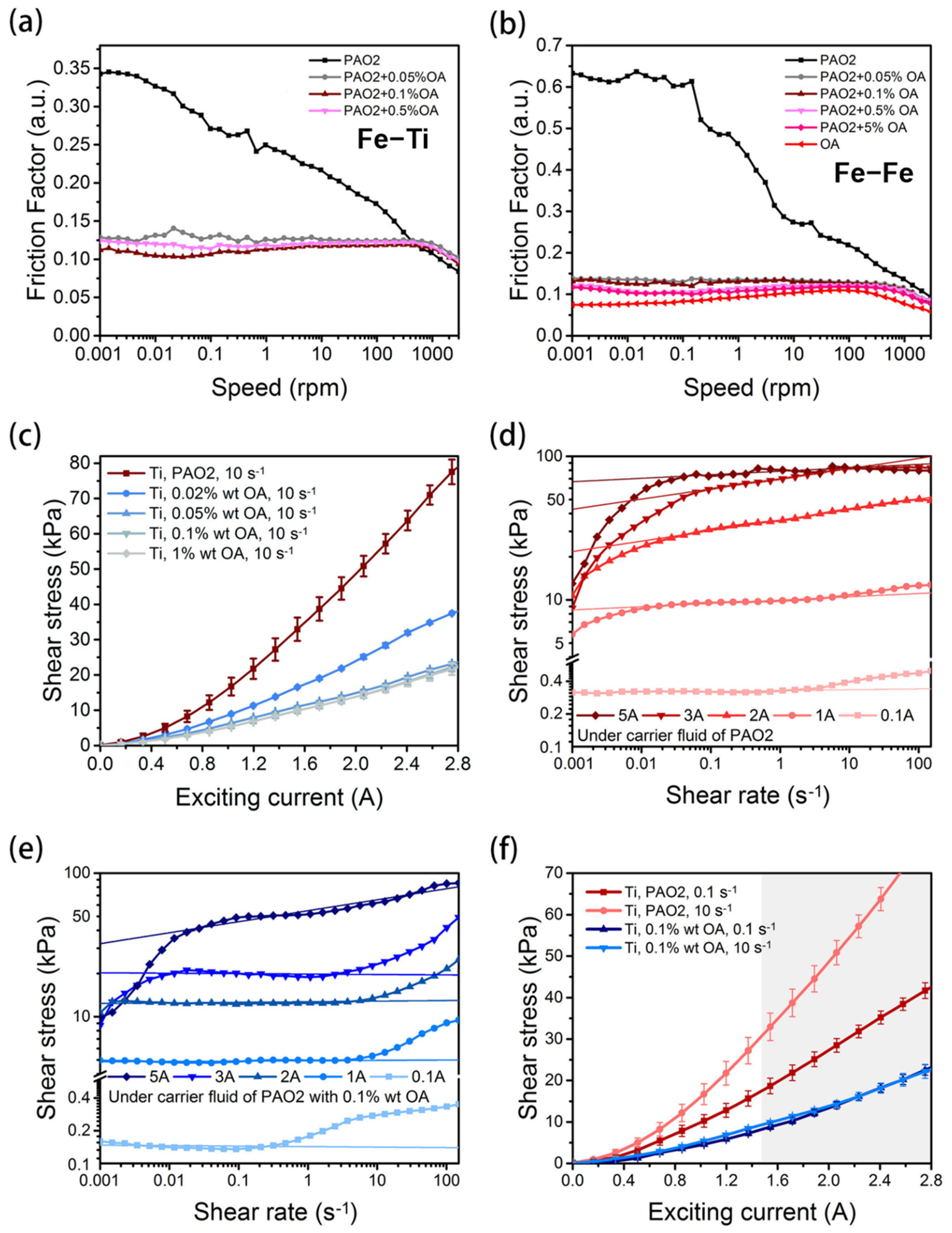
The lubricating performances of PAO2 and OA with added PAO2 are shown in Figure 1a,b. From Figure 1a, an iron steel ball (12.7 mm in diameter) and three titanium plates were chosen as the friction pairs. The addition of oleic acid significantly reduces the friction coefficient of the friction pair. At low rotational speeds, the friction coefficient decreases as the amount of oleic acid increases. However, at high rotational speeds, the difference in friction coefficients among different concentrations of oleic acid is not significant. From Figure 1b, an iron steel ball (12.7 mm in diameter) and three iron plates were chosen as the friction pairs. The addition of oleic acid significantly reduces the friction coefficient of the friction pair. The friction coefficient decreases as the amount of oleic acid increases. When the friction pair materials are all iron materials, different concentrations of oleic acid result in a more significant reduction in the friction coefficient of the friction pair. The COF under boundary lubrication decreased from approximately 0.35 to 0.12 for the Fe–Ti friction pair, and from approximately 0.6 to about 0.13 for the Fe–Fe friction pair when the concentration of OA reached 0.05 wt%. The rheological behavior also changed, and the shear stress decreased after OA was added. The reduction in shear stress reached the maximum when the concentration of OA in the carrier fluid was 0.05 wt% (Figure 1c), which corresponded to the lubricating performances of OFM that would reach its best level under a concentration of approximately 10−2 wt% [36] (Figure 1a,b). This indicated that the change in lubricating performance was the reason for the change in rheological performance. The rheological performances of MRF with a carrier fluid of pure PAO2 or PAO2 with PAO2 with 0.1 wt% OA are shown in Figure 1d,e.
As shown in Figure 1d, when 0.1%wt of oleic acid was added, the shear stress changed relatively smoothly under different excitation currents. This indicates that after adding oleic acid, the ferromagnetic particles in the magnetic fluid and the lubrication effect between the plates were better. No shear thickening phenomenon proposed by Tian et al. occurred at low shear rates [31,32,33,34]. This further demonstrates that the lubrication state between the particles and the plates of the magnetic fluid affect the force-magnetic response of the magnetic fluid.
As shown in Figure 1e, without adding oleic acid, different constant shear rates under the same excitation current will affect the shear stress of the magnetorheological fluid. When oleic acid is added, different constant shear rates have a relatively small impact on the shear stress of the magnetorheological fluid. This also indicates that when the lubrication state between the magnetic fluid particles and between the electrodes is changed, the shear stress can be significantly reduced. The lubrication state at the interface between the magnetic fluid and the electrode plate has a significant impact on the shear stress.
The yield stresses calculated using the Bingham model are listed in Table 1. The Bingham plastic model is one of the most widely employed constitutive equations for describing the flow behavior of viscoplastic materials, including cementitious pastes, drilling muds, and concentrated suspensions. In the context of steady-state shear flow, the model postulates a linear relationship between the shear stress τ and the shear rate γ ˙ once the applied stress exceeds a critical threshold, known as the yield stress [31,32]. The governing equation is expressed as:
τ = τ 0 + η 0 · γ ˙ .
where τ 0 k P a is the Bingham yield stress,  η 0   P a · s is the plastic viscosity, which corresponds to the slope of the post-yield linear region. This formulation inherently implies that the material behaves as a rigid solid when τ < τ 0 , and as a Newtonian fluid with an apparent viscosity η 0 when τ > τ 0 . It is imperative to note that the Bingham model is a two-parameter linear approximation; deviations from linearity at low shear rates are frequently observed in real systems, necessitating caution in its application. The yield stress of magnetorheological fluids based on carrier liquids with different lubricating capacities was calculated according to this equation.
The yield stress decreased by approximately 50% when OA was added under each exciting current, indicating the nonnegligible influence of OA on the yield stress. Shear stress under a test with a constant shear rate (0.1 or 10 s−1) and increasing exciting current also showed approximately 50% (shear rate = 0.1 s−1) and 70% (shear rate = 10 s−1) shear stress decreases after OA was added (Figure 1f).
Good lubricity causes a 50% or 70% loss of shear stress; however, the proportion of 50% or 70% should not be believed to be the ratio of friction to total shear stress. Good lubricity might not only reduce the friction forces but also affect the particle structures, leading to shear stress under different shear mechanisms. It is reasonable to believe that the friction between the particles and the electrode plate contributes to approximately 15% of the shear stress based on earlier studies [15,16,17,18], in which only the roughness of the electrode changed. However, the changes in lubricity varied under different experimental conditions. Although the proportion was not certain, there was evidence to show that, under good lubricity, shear would be dominated by friction behavior; under common lubricity, shear would be dominated by the breaking of the chain structure. Similar to Mn, the Stokes force and magnetic attraction were decisive, and friction and magnetic attraction also played leading roles in the shear stress transition under different conditions.
When the frictional forces were lower than the magnetic attraction when the two attached particles broke, the shear stress was dominated by the friction forces. A low shear rate and good lubrication would help in determining the friction. This might be because, under good lubrication, the friction forces were easily lower than the magnetic attraction. At high shear rates, the chain structure would inevitably be pulled apart against the magnetic attraction to provide a sufficient shear rate. Experimental evidence supports this hypothesis. When Iex < 1.5 A, simulation results showed that τ ∝ Iex1.46 at a low shear rate (0.1 s−1) and τ ∝ Iex1.69 under a high shear rate (10 s−1) (Table 2 and Table 3). The former one was explained in former studies as the “frictional yield stress” (friction forces dominated yield stress), and the latter one was called “Bingham yield stress” (magnetic attraction dominated yield stress) [37]. When OA was added, under both low and high shear rates, τ ∝ Iex1.51, which was close to 1.46 and acted like the frictional yield stress (Table 2 and Table 3). The influence of lubricity on particle structures is discussed further in the third section.
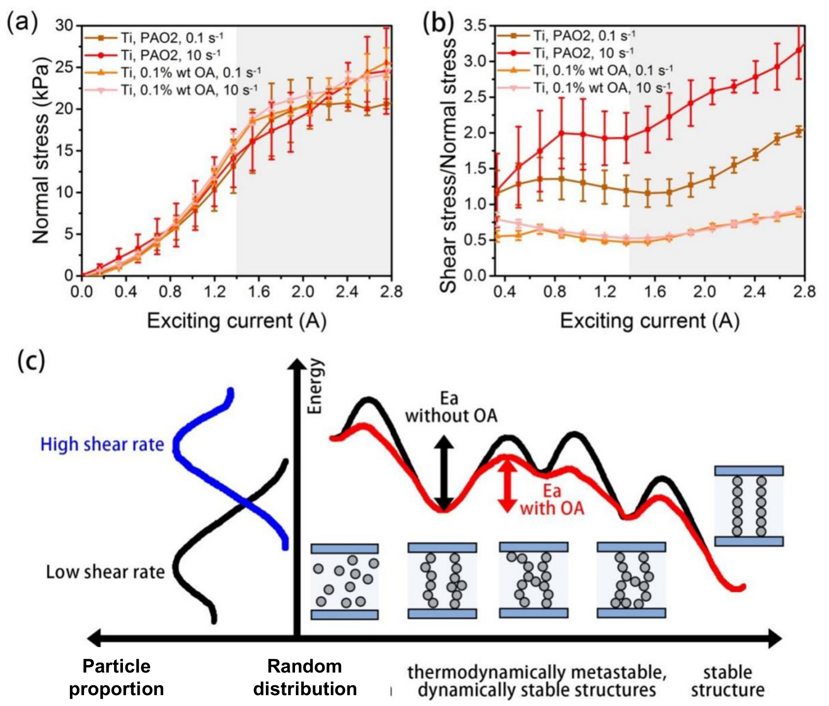
Figure 2 shows that the detailed rheological performances showed that lubricating and shearing affect the rheological performances in the same direction, and the affection of shearing became less obvious when lubricated. Figure 2a shows that in the magnetorheological experiment, when both the upper and lower plates are made of titanium material, the effect of adding oleic acid on the normal force of the MRF when the shear rate is constant. After adding oleic acid, the iron magnetic particles in the magnetorheological fluid show a decrease in normal force as the excitation current increases. This means that the excellent lubrication properties between particles and between particle plates will reduce the compression of the chain-like structure formed by ferromagnetic particles on the plates, thereby lowering their shear yield strength. Figure 2b shows the ratio of shear stress to normal stress. It is similar to the concept of the friction coefficient in tribology. It can be more intuitively observed that the ratio of shear stress to normal stress in the magnetorheological fluid after adding oleic acid has significantly decreased. And it has little correlation with the constant shear rate. This further indicates that the lubrication performance between particles and between particle plates has a significant impact on the force-magnetic response of the magnetic fluid. The normal stress (N) of the MRF worked represented by the normal pressure between particles or particles and plates, and changed in two stages with Iex. In the first stage (excitation current < 1.5 A), the positive pressure was roughly proportional to the square of the excitation current. In the second stage (excitation current > 1.5 A), the increase in normal pressure with increasing current slowed (Figure 2a,b).
The yield stress and magnetic field usually had a power-law relationship. Ferromagnetic materials have polarization saturation and the index was generally 1–2. The yield stress ( τ y ) and external magnetic induction (B) are usually described by the following equation [38]:
τ y = m · · ε · B δ .
where m was the internal characteristic parameter of the MRF, was the ferromagnetic particle volume fraction, ε was the magnetoconductivity,  δ was the internal magnetization of the MRF, and B was the magnetic induction intensity. Set m · · ε as the entirety λ , then
τ y = λ · B δ .
A theory based on the high COF hinders structural evolution was proposed. Based on previous studies [4,39], when the particle and the plate would not attract each other, the normal force of the MRF should be proportional to Iex.
Based on the above formula, the relationship between the shear stress of the magnetorheological fluid and the excitation current, as well as the relationship between the normal stress and the excitation current, were fitted.
Therefore, the τ–Iex curves before and after 1.5 A were also studied separately. The following power function was used to simulate the τ–Iex curves and the N–Iex curves:
τ = a(shear) × Iex b(shear)
N = a(normal) × Iex b(normal)
a(shear), a(normal) and b(shear), b(normal) are the fitting parameters of the shear stress, normal stress and excitation current.
The direction of the normal force is defined as positive when it is perpendicular to the upper plate and points upward. This indicates that the ferromagnetic particles of the magnetic fluid form a chain-like structure and squeeze the plate under the action of the excitation current.
The simulation results are shown in Table 2 and Table 3. Based on the previous experiments, τ and N both should be proportional to the square of the exciting current (b = 2), and the proportional coefficient, a, should not change with the lubricating performances of the carrier fluids. However, the simulation results indicate different rheological performances.
Detailed rheological performances show that lubricating and shearing affect the rheological performances in the same direction, and the effects of shearing become less obvious with lubrication.
Friction caused extra activation energy (Ea(friction)) for structure evolution, being like activation energy (Ea) in a tribochemical reaction [40,41]. Brownian forces were like the temperature, Stokes forces were like mechanical excitation, and friction modifiers were like the catalyst in tribochemical reactions. Friction might “lock” particles into a thermodynamically metastable, dynamically stable structure. Friction modifiers decreased the Ea(friction) and helped particles to form a thermodynamically stable structure state. Stokes forces excited particles and also helped particles form a thermodynamically stable structure state. Under the excitation of Stokes forces, the addition of OA has a smaller effect.
The shear-force-to-normal-force ratios were 0.5 when OA was added, which was a little higher than the COF of Fe–Ti or Fe–Fe lubricated by sufficient OA. In the absence of OA, this ratio was even higher (Figure 1c). This shows that, even with sufficient lubrication, friction and magnetic attraction contribute to the shear stress. The physical meaning of coefficient a(shear) obtained using Equation (1) is more complicated. After OA was added, the a(shear) under the Fe–Ti electrode plates decreased from approximately 10 (low shear rate) or 16 (high shear rate) to approximately 5 (Table 2 and Table 3). If the shear stress and normal stress roughly increased with the same power as the exciting current, a(shear) could represent the product of the friction coefficient and a(normal).

3.2. Friction Force as a Kind of Basic Force to Influence Rheological Performances of MRF

3.2.1. Friction Caused Evolution Activation Energy

The decrease in a(shear) can be understood as a decrease in the coefficient of friction, which results in a decrease in the shear stress. The effect of friction should not only be on shear stress, but also on the particle structures. (Figure 3a–f) As for structure formation, it was believed that Brownian forces, Stokes drag and magnetic forces are the three main forces to form a structure, and the λ parameter and the Mason number (Mn)were used to evaluate the determinate forces and therefore the structure of particles. The Mason number, Mn, is a dimensionless parameter that quantifies the relative importance of hydrodynamic viscous forces to magnetic interparticle forces in a magnetorheological fluid under shear [32]. It is defined as
M n = η γ ˙ μ 0 H 2 .
where η is the dynamic viscosity of the carrier liquid, γ ˙ is the applied shear rate, μ 0 is the vacuum permeability, and H is the external magnetic field strength. This definition follows the convention established in earlier works, in which friction forces were also not considered. In recent years, many studies suggested the influence of friction on particle structure, and these influenced structures would lead to various rheological behaviors that deviate from the Bingham model. Stick-slip as a typical friction behavior was found in MR effect. Caballero-Hernandez et al. reported that yield stress could sometimes decrease in low shear rate when applied magnetic field strength increases (shear unthickening). Tian et al. proposed the shear thickening and unthickening phenomenon of MRF [31,32]. When the shear rate or applied magnetic field strength increased, shear stress would suddenly “jump up”. When the applied magnetic field strength is high enough, the shear stress would suddenly decrease and the normal force suddenly increased. These phenomena were explained by the friction mode change within MRF. Compared with the influence of friction on shear stress, the influence of friction on structure evolutions was less studied, but it affects the rheological behavior and yield stress of MRF.
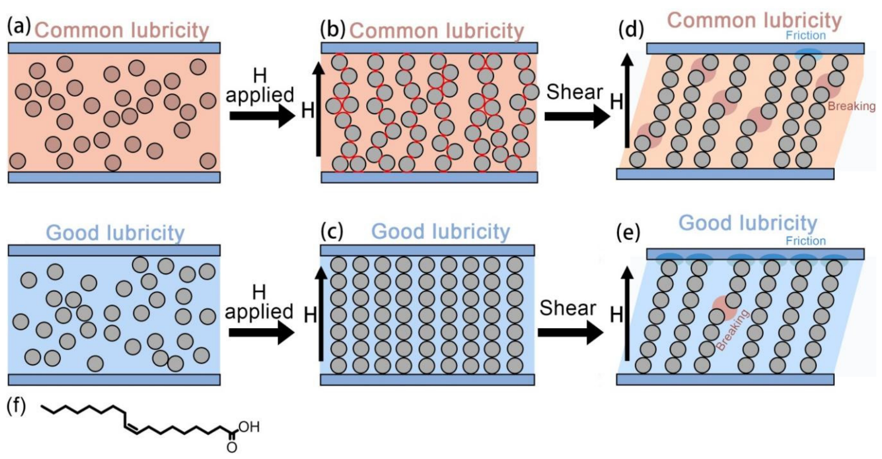
Figure 3a shows the friction between particles and electrode plates. Friction could be a part of shear force transfer. Figure 3b shows that, like Brownian forces, Stokes drag, and magnetic forces, friction forces are a kind of force within a magnetorheological system and could influence the structure evolution of particles. Friction might “lock” particles into a thermodynamically metastable, dynamically stable structure. Figure 3c shows that the friction modifiers decreased the Ea(friction) and helped particles to form thermodynamically stable structure state. Figure 3d,e, show that the friction between particles and electrode plates. Friction could be a part of shear force transfer. In the structural evolution, Stokes forces excited particles and also helped particles to form a thermodynamically stable structure state. Under the excitation of Stokes forces, the lubricating performances might have less effect on structure evolution. Figure 3f is Structure of OA.
This work attempts to study the effect of friction on the yield stress and the way it affects the particle structure in MRF. In this study, yield behaviors of MRFs with common and good lubricating performances were tested. Oleic acid (OA, Figure 3f), an organic friction modifier, could reduce boundary friction with little change in viscosity. Therefore, the carrier fluids of PAO2 represented the “common lubricity”, and the carrier of PAO2 with OA represented the “good lubricity”. OA is always added in MRF as a surfactant to decline the settling of ferroparticle in MRF, and there were few reports that OA reduced yield stress. However, MRFs worked under titanium–iron plates showed about 50% yield stress reduction after 0.1 wt% OA added, which was higher than most of the previous studies about friction to yield stress of MRF. The ratio of tangential force to normal force was also reduced, being closer but still higher to the coefficient of friction (COF) of Fe–Fe or Fe–Ti lubricated by its carrier fluids with OA. This suggested that friction, being along with magnetic forces, should be a main part as shear transfer. Rheological performances also showed complex changes. The shear thickening phenomenon was more difficult to happen and that required higher applied magnetic field strength. “Better lubricating performances of carrier fluids” and “higher shear rate” (when the shear rate was not too high) often led to the same effect. These results suggested that along with Brownian forces, Stokes drag and magnetic forces, friction was a factor on structure evolution.
Three rheological details require attention. First, there have been many previous studies on the influence of friction on the yield stress of MRF that reported that the shear stress change ratio was concentrated at approximately 15%. Kieburg et al. studied MRF under brass electrode plates, resulting in a 16% increase in yield stress when the plate became rougher [16]. Wu et al. found that an increase in shear stress of up to 17% was caused by a rougher sandpaper electrode plate [17]. Peng et al. found that 5 kPa (10–20%) differences in yield stress were caused when the COF between the electrode plate and the particle chain changed from 0.1 to 0.4 [18]. However, these ratios were much lower than that in this study (50% or 70% when OA was added). These previous studies changed the COF between the plate and the particles; however, in this study, the entire lubricating performances of the carrier fluids changed. This implies that, under good lubricity, not only is there a decrease in friction forces as a part of the shear stress, but also there are more structural changes.
Second, experimental results showed that, under a low shear rate (0.1 s−1), the normal force was Iex1.69. The addition of OA (N ∝ Iex1.95) or increase in shear rate (N ∝ Iex1.85 when shear rate = 10 s−1 and no OA is added) would both increase the power (Table 2). The power changed slightly with the addition of OA for the MRF under a high shear rate, where N was Iex1.84 (Table 3 and Figure 2a). High lubricating performance and a high shear rate influenced the rheological behavior in the same direction.
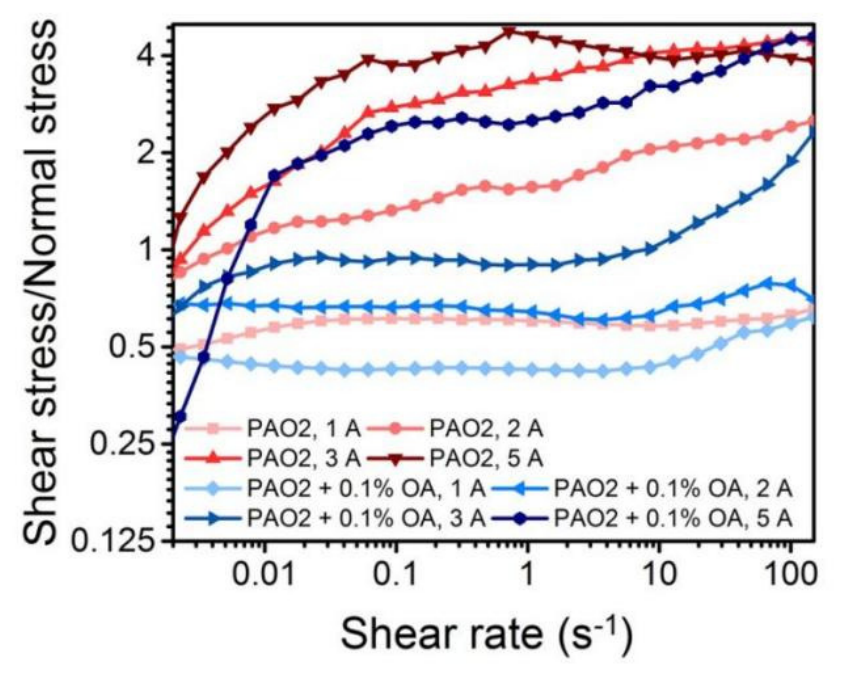
Moreover, in the shear-stress–Iex relationship, an increase in the lubrication effect implies a decrease in the influence of the shear rate. In the field-changing experiment, the shear stress varied under different constant shear rates for all Iex. However, this difference mostly decreased when OA was added (Figure 3e). The small change in the ratio of shear stress to normal stress (τ/N) when shear rate changed under OA lubrication (Figure 2a), (b) also supports this. Under low-lubrication conditions, τ/N under high or low shear rates differed greatly, and both were higher than one. Under good lubrication conditions, the difference in τ/N under high/low shear rates was very small (both approximately 0.5). Many previous studies have reported that the influence of the surface roughness becomes much less obvious when Iex increases. Gómez-Ramírez et al. found that increasing the surface roughness of the electrode resulted in a higher yield stress; however, when the applied magnetic field increased, the increment decreased [15,17]. However, when OA was added, under all magnetic field strengths, the MRF showed a decreased yield stress. This implies that not only the wall slip but also the friction between particles affects the yield stress, and friction may affect the structure of the MRF.
A theory based on the high COF that hinders structural evolution was proposed. Based on previous studies, when the particle and the plate do not attract each other, the normal force of the MRF should be proportional to Iex 2–2.4 [39,42,43]. However, this conclusion is based on the assumption that a chain35 or body-centered tetragonal (BCT) structure formed between the particles. Friction, similar to the Brownian motion, Stokes force, and magnetic force, also affects the structural evolution of the MRF [31,32]. Friction is part of the structural evolution activation energy (Ea(friction)), which slows down structural evolution and forces the formation of dynamically stable structures. In contrast, Stokes and Brownian forces break and reorganize the formed structures, making the structure thermodynamically stable. If Ea(friction) is compared to the activation energy in a tribochemical reaction [44,45], then Brownian forces should be thermal excitation, and Stokes forces should be mechanical excitation, which increase the energy of particles to help them “go across” Ea (Figure 2c).
At low shear rates and without lubrication, the Stokes force is not sufficiently strong, causing the particle structure to remain in a metastable state, which causes the normal force to deviate from the theoretical power with a change in Iex (Figure 3b,c). The shear stress is higher because the activation energy of the structural evolution is high. Therefore, in addition to dynamic friction and magnetic force, shear stress is also necessary to overcome the force that causes the structure to evolve, resulting in an increase in shear stress. After OA is added, Ea(friction) should decrease; therefore, the structure becomes the thermodynamically stable structure predicted by theory (Figure 3c).
Thus, friction modifiers act as catalysts in tribochemistry (Figure 3c). When the shear rate is high, the Stokes forces as a mechanical excitation also help to reduce Ea and bring the power closer to the theoretical value (Figure 3d,e). Similar to the tribochemical reaction of mechanical excitation, which is less sensitive to temperature or other catalysts, under high shear stress, the addition of OA causes little change in the power because Ea(friction) was already overcome by Stokes forces (Figure 3d). The power value of 1.85 < 1.95 may result from the thermodynamically stable changes from chain-like to partly layeredlike.
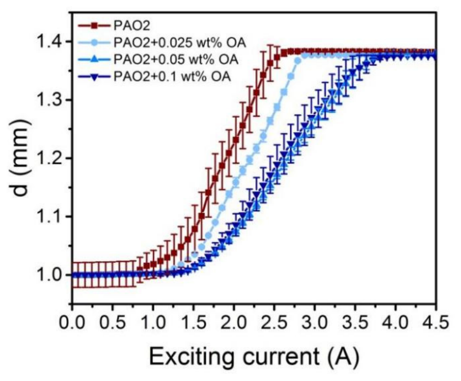
At the beginning of the experiment, the gap between the electrodes was set to 1 mm. As the magnetic field increases, the ferromagnetic particles gradually form a chain-column structure and compress the upper electrode plate. As a result, the gap between the electrodes changes and becomes larger than the initially set gap. The change in the gap between the two plates (d) when the MRF was operating was notable. An unstable d changes the volume of the MRF working space, affects the contact area of the MRF with the electrode plates, and ultimately affects the efficiency of torque transmission. The experiments showed that, when Iex exceeds a certain value, d increases as Iex increases. When the lubricating performance of the carrier fluid became better, the required “certain value of Iex that caused increasing d” increased, which meant d was stable in a wider Iex range (Figure 4).
This can also be explained by friction as an activation energy that hinders structural evolution. At a high COF, the particles may not squeeze smoothly into the chain structure. The particles attached to the side of the chain had a large static friction force, and the component in the direction normal to the pole plate was also large. Static friction also hinders the particles from undergoing other structural evolutions, such as falling off the attached chain to form a new chain (Figure 3b). When the exciting current increased so that the magnetic attraction force that drew the particles into the chain structure was greater than the static friction force, the particles were attracted to the chain structure, resulting in a longer chain length and a larger d. When the COF between particles was low, the activation energy of the chain structure evolution was also low (Figure 3c), and particles not squeezed into the formed chain could undergo structural evolution, such as reorganization into a new chain. Therefore, the increase in d with Iex was postponed.

3.2.2. Low Friction Caused More Rolling of Particles

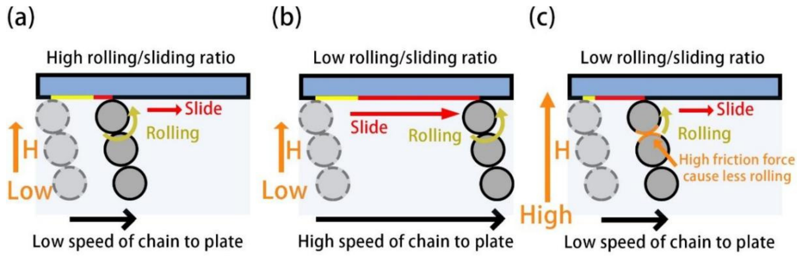
The rolling/sliding ratio of the particles was high at low speeds; therefore, it was not sensitive to the addition of OA (Figure 5a–c).The rolling of particles is believed to be universal in MR effects [33,34,35,36]. When a particle moves horizontally with a high rolling/slip ratio, τ is lower than for one that moved with a low rolling/slip ratio or underwent separation. Low friction and low shear rate are the basis for a high rolling/slip ratio. Under a high excitation current or high friction coefficient, the frictional forces between the particles or between the particles and polar plates are relatively large, which hinders the rolling of the particles. When the shear rate increases, rolling does not provide sufficient horizontal speed; therefore, the rolling/slide ratio also decreases. This is also considered to be the reason for the shear-thickening phenomenon of the MRF [31,32]. At low speed and OA lubrication, the rolling/slip ratio remains high; therefore, the power of τ to Iex should be lower than the predicted value of 2.0.
The shear thickening phenomenon when increasing the applied magnetic field forces or shear rate (when the shear rate was very low) in MR effects was reported and attributed to the rolling–slide ratio changes when the shear rate or applied magnetic field strength increased. As shown in Figure 6, OA had no effect on the inherent shear thickening under a high shear rate of solid dispersions with a high-volume fraction.
However, OA caused the shear thickening phenomenon (under low shear rate) of MRF to disappear under lower current. This might be because the low COF between particles and of particles to plates did not “lock” the rolling. When the exciting current became higher, the shear thickening phenomenon did not vanish but was delayed to approximately 0.01 s−1. This might be because a low COF makes the particles easier to roll.
The yield behaviors of MRFs with common and good lubricating performances were tested. Oleic acid (OA), as shown in Figure 1f, an organic friction modifier, can reduce boundary friction with little change in viscosity [35]. Therefore, the carrier fluids of PAO2 exhibited “common lubricity,” and the carrier of PAO2 with OA exhibited “good lubricity.” OA is always added to MRF as a surfactant to reduce the settling of ferroparticles, and there have been a few reports that OA reduced yield stress. However, MRFs working under titanium–iron plates showed an approximately 50% yield stress reduction after 0.1 wt% of OA was added, which was higher than reported in most previous studies on the friction to yield stress of MRF. The ratio of the tangential force to the normal force was also reduced, being closer to but still higher than the coefficient of friction (COF) of Fe–Fe or Fe–Ti lubricated by carrier fluids with OA. This suggests that friction, along with magnetic forces, is the main contributor to the shear transfer. The rheological performance also exhibited complex changes. Shear thickening was less likely to occur and required a higher applied magnetic field strength. “Better lubricating performances of carrier fluids” and higher shear rate [33]” (when the shear rate was not too high) often led to the same effect. These results suggest that, along with Brownian forces, Stokes drag, and magnetic forces, friction is a factor in structural evolution.

4. Conclusions

In this article, the main approach is to alter the proportion of oleic acid added, and under different friction pairs of materials and plate materials (fe–fe/fe–ti), to change the lubrication state between particles and the plates in the magnetic fluid. By regulating the key interface friction lubrication state within the MRF, the force/magnetic response phenomenon of the MRF is changed. The experimental results all demonstrate that the lubrication state of the key interface within the MR affects the shear stress and yield stress of the magnetic fluid, and can regulate the magnetic fluid effect. The specific conclusions obtained are as follows:
1. Friction forces are believed to be part of the shear stress. The higher lubricating performance of the carrier fluid results in lower friction forces between particles and particles with plates, always leading to a lower yield stress. Lower friction forces and shear stress cause the friction forces to have a higher ratio within the shear stress. In terms of rheological details, lubrication and a high shear rate often have the same effect on rheological performance. The added oleic acid affects the lubrication state between the ferromagnetic particles within the magnetic fluid as well as between the particles and the electrode plates, thereby influencing the shear stress and yield stress of the magnetic fluid. Moreover, the better the lubrication state, the smaller the shear stress and yield stress of the prepared magnetic fluid.
2. The normal force changes with an exciting current of lower power when the MRF works under a low shear rate and lower lubricating performance. Low friction caused more rolling of particles. When a magnetic fluid is subjected to an external magnetic field (with an excitation current), the ferromagnetic particles within it rapidly form a chain-like structure that squeezes the electrodes, thereby generating a normal stress. After adding OA, the chain column-like structure formed by the MRFs reduces the friction force between the electrodes. When the friction force is sufficiently low, the chain column-like structure and the electrode interface gradually undergo rolling motion as the shear rate increases. This can be attributed to the formation of thermodynamically metastable and dynamically stable structures. The friction is similar to the activation energy that hinders the structural evolution. Low friction and low applied field strength also make it easier for the particles to roll, causing a delay in shear thickening.
3. A critical value exists for the mass fraction of added OA. When the mass fraction is lower than the critical value, the higher the mass fraction, the better the lubrication performance of the base fluid, and the lower the shear stress of the MRFs. The optimal addition mass fraction of oleic acid in this study was 0.05%wt. Beyond this addition ratio, the impact on the mechanical properties of the magnetic fluid was not significantly different. This 0.05%wt of oleic acid may have been fully adsorbed between particles and the plates, and the change in lubrication performance has been the most significant. This research provides an effective theoretical basis for the formulation design and preparation of magnetic fluid. The magnetic fluid effect can be regulated by adjusting the lubrication performance of the base liquid. This provides a new design theory for the formulation of MRFs, thereby reducing design costs and improving production efficiency.

Author Contributions

Conceptualization, Y.Z. and B.J.; methodology, C.O.; validation, Y.M., Y.Z. and C.O.; formal analysis, B.J. and X.W.; investigation, H.W.; resources, Y.M.; data curation, C.O.; writing—original draft preparation, C.O. and Y.Z.; writing—review and editing, Y.Z.; visualization, H.W.; supervision, B.J.; project administration, C.O.; funding acquisition, H.W. All authors have read and agreed to the published version of the manuscript.

Funding

This work was supported by the National Natural Science Foundation of China (No. 52305190).

Data Availability Statement

The original contributions presented in the study are included in the article.

Acknowledgments

We thank all editors and reviewers for their suggestions and comments.

Conflicts of Interest

The authors declare no conflicts of interest.

Abbreviations

a(shear)Coefficient simulated by the formula τ = a(shear) × Iex b(shear)
a(normal)Coefficient simulated using the formula N = a(normal) × Iex b(normal)
b(shear)Coefficient simulated by the formula τ = a(shear) × Iex b(shear)
b(normal)Coefficient simulated using the formula N = a(normal) × Iex b(normal)
IexExciting current
MnMason number
MReffect Magnetorheological effect
MRFMagnetorheological fluid
NNormal stress
OFMOrganic friction modifiers
τShear stress

References

  1. Ahamed, R.; Choi, S.-B.; Ferdaus, M.M. A state of art on magneto-rheological materials and their potential applications. J. Intell. Mater. Syst. Struct. 2018, 29, 2051. [Google Scholar] [CrossRef]
  2. Phu, D.X.; Choi, S.-B. Magnetorheological fluid based devices reported in 2013–2018: Mini-review and comment on structural configurations. Front. Mater. 2019, 6, 19. [Google Scholar] [CrossRef]
  3. Klingenberg, D.J. Magnetorheology Applications and challenges. AIChE J. 2001, 47, 246. [Google Scholar] [CrossRef]
  4. de Vicente, J.; Klingenberg, D.J.; Hidalgo-Alvarez, R. Magnetorheological fluids: A review. Soft Matter 2011, 7, 3701. [Google Scholar] [CrossRef]
  5. Kordonski, W.G.; Golini, D. Multiple application of magnetorheological effect in high precision finishing. J. Intell. Mater. Syst. Struct. 2002, 13, 401. [Google Scholar] [CrossRef]
  6. Rabinow, J. The magnetic fluid clutch. Trans. Am. Inst. Electr. Eng. 1948, 67, 1308. [Google Scholar] [CrossRef]
  7. Chen, J.Z.; Liao, W.H. Design, testing and control of a magnetorheological actuator for assistive knee braces. Smart Mater. Struct. 2010, 19, 035029. [Google Scholar] [CrossRef]
  8. Klingenberg, D.J.; Zukoski, C.F. Studies on the steady-shear behavior of electrorheological suspensions. Langmuir 1990, 6, 15. [Google Scholar] [CrossRef]
  9. Bossis, G.L.; Lemaire, E.; Volkova, O.; Clercx, H. Yield stress in magnetorheological and electrorheological fluids: A comparison between microscopic and macroscopic structural models. J. Rheol. 1997, 41, 687. [Google Scholar] [CrossRef]
  10. Wu, J.; Kong, W.; Liu, Y. Structural development of magnetorheological fluid brakes/clutches as typical transmission devices: A review. J. Magn. Magn. Mater. 2025, 614, 172697. [Google Scholar]
  11. Gehin, C.; Persello, J.; Charraut, D.; Cabane, B. Electrorheological properties and microstructure of silica suspensions. J. Colloid Interface Sci. 2004, 273, 658. [Google Scholar] [CrossRef] [PubMed]
  12. Buscall, R. Letter to the Editor: Wall slip in dispersion rheometry. J. Rheol. 2010, 54, 1177. [Google Scholar] [CrossRef]
  13. Hu, Z.D.; Yan, H.; Qiu, H.Z.; Zhang, P.; Liu, Q. Friction and wear of magnetorheological fluid under magnetic field. Wear 2012, 278–279, 48–52. [Google Scholar] [CrossRef]
  14. Bossis, E.L.; Bossis, G. Yield stress and wall effects in magnetic colloidal suspensions. J. Phys. D Appl. Phys. 1991, 24, 1473. [Google Scholar] [CrossRef]
  15. Gómez-Ramírez, A.; López-López, M.T.; González-Caballero, F.; Durán, J.D.G. Wall slip phenomena in concentrated ionic liq-uid-based magnetorheological fluids. Rheol. Acta 2012, 51, 793. [Google Scholar] [CrossRef]
  16. Laun, H.M.; Gabriel, C.; Kieburg, C. Wall material and roughness effects on transmittable shear stresses of magnetorheological fluids in plate–plate magnetorheometry. Rheol. Acta 2011, 50, 141. [Google Scholar] [CrossRef]
  17. Wu, R.; Tang, H.; Fu, Y.; Zheng, J.; Lin, H.; Huang, H.; Chen, S. Study on wall-slip effect of magnetorheological fluid and its influencing factors. J. Intell. Mater. Syst. Struct. 2022, 33, 352–364. [Google Scholar]
  18. Peng, X.Q.; Shi, F.; Dai, Y.F. Magnetorheological fluids modelling: Without the no-slip boundary condition. Int. J. Mater. Prod. Technol. 2008, 31, 27. [Google Scholar] [CrossRef]
  19. Roupec, J.; Mazůrek, I.; Strecker, Z.; Klapka, M. The behavior of the MR fluid during durability test. J. Phys. Conf. 2013, 412, 012024. [Google Scholar] [CrossRef]
  20. Li, W.H.; Zhang, X.Z. The effect of friction on magnetorheological fluids. Korea-Aust. Rheol. J. 2008, 20, 45–50. [Google Scholar]
  21. Halsey, T.C.; Toor, W. Fluctuation-induced couplings between defect lines or particle chains. J. Stat. Phys. 1990, 61, 1257. [Google Scholar] [CrossRef]
  22. Halsey, T.C.; Toor, W. Structure of electrorheological fluids. Phys. Rev. Lett. 1990, 65, 2820. [Google Scholar] [CrossRef] [PubMed]
  23. Martin, J.E.; Odinek, J.; Halsey, T.C. Evolution of structure in a quiescent electrorheological fluid. Phys. Rev. Lett. 1992, 69, 1524. [Google Scholar] [CrossRef] [PubMed]
  24. Martin, J.E.; Odinek, J.; Halsey, T.C.; Kamien, R. Structure and dynamics of electrorheological fluids. Phys. Rev. E 1998, 57, 756. [Google Scholar] [CrossRef]
  25. Furst, E.M.; Gast, A.P. Micromechanics of magnetorheological suspensions. Phys. Rev. E 2000, 61, 6732. [Google Scholar] [CrossRef]
  26. Volkova, O.; Bossis, G.; Guyot, M.; Bashtovoi, V.; Reks, A. Magnetorheology of magnetic holes compared to magnetic particles. J. Rheol. 2000, 44, 91. [Google Scholar] [CrossRef]
  27. Klingenberg, D.J.; Ulicny, J.C.; Golden, M.A. Mason numbers for magnetorheology. J. Rheol. 2007, 51, 883. [Google Scholar] [CrossRef]
  28. Kumbhar, B.K.; Patil, S.R. A study on properties and selection criteria for magnetorheological (MR) fluid components. Int. J. ChemTech Res. 2014, 6, 3303–3306. [Google Scholar]
  29. Caballero-Hernandez, J.G.-R.; Duran, J.D.G.; Gonzalez-Caballero, F.; Zubarev, A.Y.; Lopez-Lopez, M.T. On the effect of wall slip on the determination of the yield stress of magnetorheological fluids. Appl. Rheol. 2017, 27, 15001. [Google Scholar]
  30. Tian, Y.; Zhu, X.; Jiang, J.; Meng, Y.; Wen, S. Structure factor of electrorheological fluids in compressive flow. Smart Mater. Struct. 2010, 19, 105024. [Google Scholar] [CrossRef]
  31. Tian, Y.; Jiang, J.; Meng, Y.; Wen, S. A shear thickening phenomenon in magnetic field controlled-dipolar suspensions. Appl. Phys. Lett. 2010, 97, 151904. [Google Scholar] [CrossRef]
  32. Tian, Y.; Zhang, M.; Jiang, J.; Pesika, N.; Zeng, H.; Israelachvili, J.; Meng, Y.; Wen, S. Reversible shear thickening at low shear rates of electrorheological fluids under electric fields. Phys. Rev. E Stat. Nonlinear Soft Matter Phys. 2011, 83, 011401. [Google Scholar] [CrossRef]
  33. Zhang, Y.; Jiang, J.; Ouyang, C.; Wen, G.; Meng, Y.; Tian, Y. Effect of nano-silica-particle additive on magnetorheological behavior. Rheol. Acta 2022, 61, 785. [Google Scholar] [CrossRef]
  34. Zhang, Y.; Jiang, J.; Wen, G.; Ouyang, C.; Meng, Y.; Jia, W.; Tian, Y. Influence of magnetic property of test plates on magnetorhe-ological behavior. Smart Mater. Struct. 2022, 31, 055015. [Google Scholar] [CrossRef]
  35. Spikes, H. Friction modifier additives. Tribol. Lett. 2015, 60, 5. [Google Scholar] [CrossRef]
  36. Zhang, Y.; Jiang, J.; Ouyang, C.; Meng, Y.; Jia, W.; Ma, L.; Tian, Y. Effect of base oil lubrication properties on magnetorheological fluids. Smart Mater. Struct. 2021, 30, 095011. [Google Scholar] [CrossRef]
  37. Bossis, G.; Khuzir, P.; Lacis, S.; Volkova, O. Yield behavior of magnetorheological suspensions. J. Magn. Magn. Mater. 2003, 258, 456. [Google Scholar] [CrossRef]
  38. Felicia, L.J.; Philip, J. Magnetorheological properties of a magnetic nanofluid with dispersed carbon nanotubes. Phys. Rev. E 2014, 89, 022310. [Google Scholar] [CrossRef]
  39. de Vicente, J.; González-Caballero, F.; Bossis, G.; Volkova, O. Normal force study in concentrated carbonyl iron magnetorhe-ological suspensions. J. Rheol. 2002, 46, 1295. [Google Scholar] [CrossRef]
  40. Kajdas, C.K.; Kulczycki, A.; Kurzydlowski, K.J.; Molina, G.J. Activation energy of tribochemical and heterogeneous catalytic reactions. Mater. Sci.-Pol. 2010, 28, 523–533. [Google Scholar]
  41. Molina, G.J.; Kajdas, C.; Furey, M.J.; Ritter, A.L. Importance of low-energy triboelectrons for the initiation of tribochemical reactions. Tribologia 2003, 1, 103–122. [Google Scholar]
  42. Das, M.; Jain, V.K.; Ghoshdastidar, P.S. Fluid flow analysis of magnetorheological abrasive flow finishing (MRAFF) process. Int. J. Mach. Tool. Manuf. 2008, 48, 415. [Google Scholar] [CrossRef]
  43. Laun, H.M.; Gabriel, C.; Schmidt, G. Primary and secondary normal stress differences of a magnetorheological fluid (MRF) up to magnetic flux densities of 1 T. J. Non-Newton. Fluid Mech. 2008, 148, 47. [Google Scholar] [CrossRef]
  44. Kajdas, C.; Kulczycki, A.; Ozimina, D. A new concept of the mechanism of tribocatalytic reactions induced by mechanical forces. Tribol. Int. 2017, 107, 144–151. [Google Scholar] [CrossRef]
  45. Kajdas, C.K.; Kulczycki, A. A new idea of the influence of solid materials on kinetics of chemical reactions. Mater. Sci.-Pol. 2008, 26, 787–796. [Google Scholar]
Figure 1. Better lubricating performances of a carrier would significantly decrease the shear force. (a,b) Lubricating performances of carrier fluids with different concentrations of OA under the friction pair of (a) Fe−Ti or (b) Fe−Fe. (c) Rheological performances of MRF with the carrier fluid of PAO2 or (d) PAO2 with PAO2 with 0.1 wt% OA. (e) Shear-stress−Iex curve of MRF under Fe−Ti plates under shear rates of 0.1 and 10 s−1. (f) Shear-stress−Iex curves under the different concentrations of OA.
Lubricants 14 00276 g001
Figure 2. The influence of oleic acid on the MR mechanical effect. (a) The N−Iex curve of MRF for Fe−Ti electrode plates. (b) The curve of the shear-stress–normal-stress ratio (τ/N) changing with Iex. (c) Proposed mechanism.
Lubricants 14 00276 g002
Figure 3. The tribological effects of OA on the internal particles of MRF. (a) Common lubricity. (b) After applying a magnetic field with common lubricity. (c) Good lubricity and apply a magnetic field. (d) Shear with common lubricity, (e) Good lubricity and apply a magnetic field by sheared. (f) Structure of OA.
Lubricants 14 00276 g003
Figure 4. The distance between two electrode plates changed with exciting current under carrier fluids with good or poor lubricating performances.
Lubricants 14 00276 g004
Figure 5. Rolling/slip ratio influenced by the frictional forces between particles and plates and the shear rate. (a) High rolling ratio under low speed; (b) High sliding ratio under high speed; (c) High sliding ratio under low speed with friction.
Lubricants 14 00276 g005
Figure 6. The τ/N-shear rate curve of MRF with or without OA (Fe−Ti electrode plate).
Lubricants 14 00276 g006
Table 1. Yield stress reduced proportion of yield stress and of MRF with carrier fluid of PAO2 and carrier fluid of PAO2 with 0.1 wt% OA.
Iex (A)Yield Stress (kPa)Reduced Proportion of Yield Stress
PAO2PAO2 with 0.1 wt% OA
0.10.320.1456%
18.54.943%
221.712.443%
342.920.253%
566.732.352%
Table 2. Parameters of the fitting equation for shear stress and normal stress of MRFs and excitation current under a constant shear rate of 0.1 s−1 under Fe–Fe plate and Ti–Fe plate.
Stress (kPa)Fe–Fe PlateTi–Fe Plate
0.1 s−10.1 s−1
a(shear)a(shear) with OAb(shear)b(shear) OAa(shear)a(shear) with OAb(shear)b(shear) OA
τ (Iex: 0A–1.4A)12.4 ± 0.213.0 ± 0.11.80 ± 0.021.72 ± 0.0210.1 ± 0.34.7 ± 0.21.46 ± 0.041.51 ± 0.07
τ (Iex: 1.4A–2.8A)10.4 ± 0.213.7 ± 0.82.17 ± 0.031.67 ± 0.0710.7 ± 0.24.3 ± 0.11.34 ± 0.021.62 ± 0.01
τ (Iex: 0A–2.8A)10.7 ± 0.512.9 ± 0.92.11 ± 0.051.66 ± 0.0611.1 ± 0.44.4 ± 0.11.33 ± 0.031.61 ± 0.02
Normal stress 2.41 ± 0.012.61 ± 0.011.69 ± 0.021.95 ± 0.01
Table 3. Parameters of the fitting equation for shear stress and normal stress of MRFs and excitation current under a constant shear rate of 10 s−1 under Fe–Fe plate and Ti–Fe plate.
Stress (kPa)Fe–Fe PlateTi–Fe Plate
10 s−110 s−1
aa Under OAbb Under OAaa Under OAbb Under OA
τ (Iex: 0A–1.4A)15.7 ± 0.314.0 ± 0.21.95 ± 0.041.64 ± 0.0315.9 ± 0.25.2 ± 0.11.69 ± 0.021.51 ± 0.02
τ (Iex: 1.4A–2.8A)17.2 ± 0.912.8 ± 0.71.92 ± 0.081.75 ± 0.0717.4 ± 0.15.2 ± 0.11.48 ± 0.011.43 ± 0.02
τ (Iex: 0A–2.8A)15.9 ± 0.712.6 ± 0.82.02 ± 0.101.74 ± 0.0617.7 ± 0.45.2 ± 0.11.48 ± 0.021.42 ± 0.01
Normal stress 2.67 ± 0.062.61 ± 0.021.85 ± 0.121.84 ± 0.03
Disclaimer/Publisher’s Note: The statements, opinions and data contained in all publications are solely those of the individual author(s) and contributor(s) and not of MDPI and/or the editor(s). MDPI and/or the editor(s) disclaim responsibility for any injury to people or property resulting from any ideas, methods, instructions or products referred to in the content.