


Abstract
The pantograph–catenary system (PCS) is a critical component through which electrified railway trains obtain electrical energy, and the current-carrying friction and wear behavior at the pantograph–catenary interface directly affect current collection quality and operational safety. Water environments, particularly icing conditions, may induce contact instability, arc ablation, and abnormal wear. Therefore, this paper provides a comprehensive review of research progress on the current-carrying friction and wear behavior of C/Cu contact pairs under water environments. It focuses on the interfacial evolution characteristics under three different phase states of water and analyzes their influence mechanisms on lubrication conditions, current transmission, and wear behavior. Typical protection strategies, including speed restriction, mechanical de-icing, thermal de-icing, and anti-icing measures, are summarized, and their applicability and current development status are discussed. Finally, it is suggested that future research should focus on the development of high-performance carbon strip materials, accurate monitoring of ice morphology and types, and efficient hybrid anti-/de-icing technologies, thereby ensuring the reliable operation of high-speed railways under icing conditions.
1. Introduction
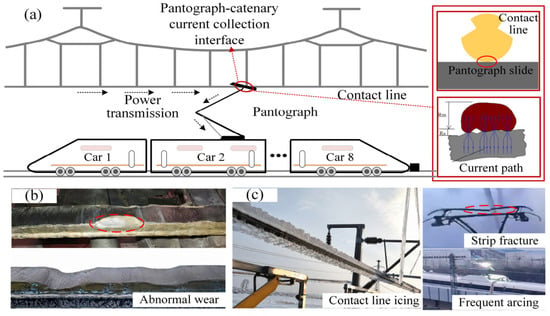
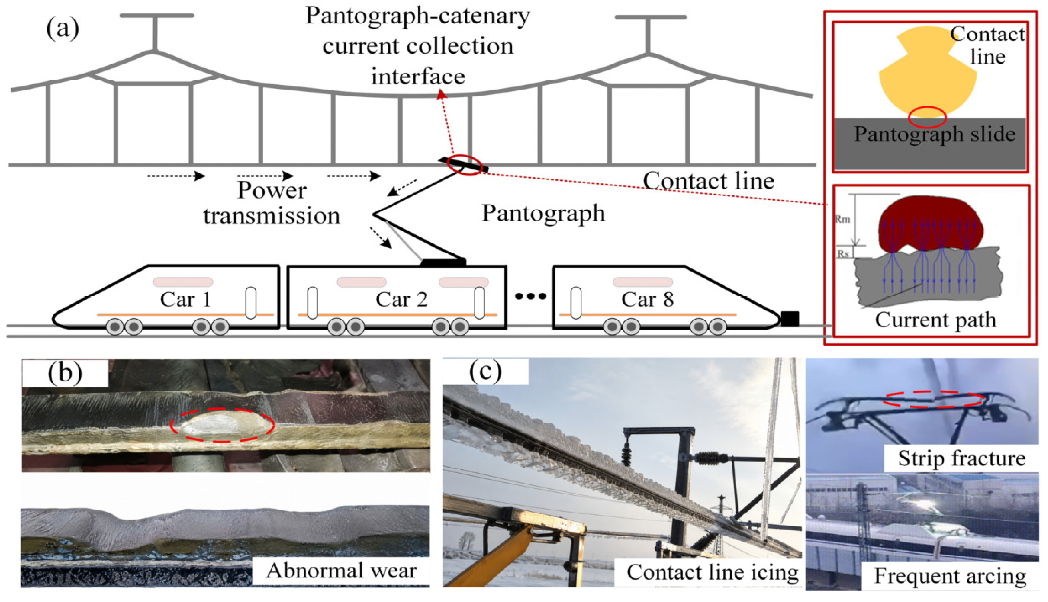
High-speed railways, as the main arteries of the national economy and a mass transportation mode, play an important role in socio-economic development [1]. As the core component for power transmission in high-speed railways, the PCS transmits electrical energy through C-Cu sliding electrical contacts, which is the only route for energy transmission in trains [2,3,4] (shown in Figure 1a). However, due to the long-term operation of the PCS in open and complex environments, abnormal wear phenomena such as spalling of the pantograph contact strip, dense arc ablation pits, and uneven wear frequently occur [5,6]. These issues lead to significant degradation in the service performance and lifespan of the strips [7,8]. Therefore, to ensure the safety and stability of energy transmission in high-speed railway systems, studying the friction and wear behavior of C–Cu materials has become an important topic [9,10].
Figure 1.
(a) High-speed railway PCSs; (b) abnormal wear in humid/rainy environments; (c) damage in icing environment.
At present, research on the current wear of C-Cu pairs mainly focuses on the effects of operating conditions such as current [11], load [12,13], and speed [14,15]. However, in recent years, the pantograph carbon strip has frequently exhibited seasonal abnormal wear. This indicates that dynamic changes in external service environments, such as temperature and humidity, have become a key factor affecting the current-carrying friction and wear characteristics of PCSs [16,17,18,19,20]. Additionally, during daily operations, high-speed railways often face alternating environmental conditions such as high temperatures, low temperatures, and rainfall. These factors directly or indirectly alter the contact conditions on the friction surfaces, ultimately impacting their tribological behavior.
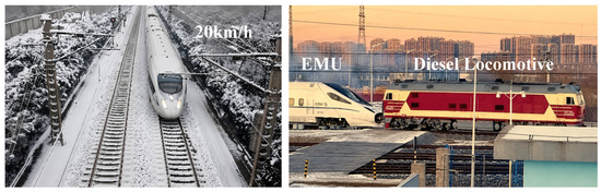
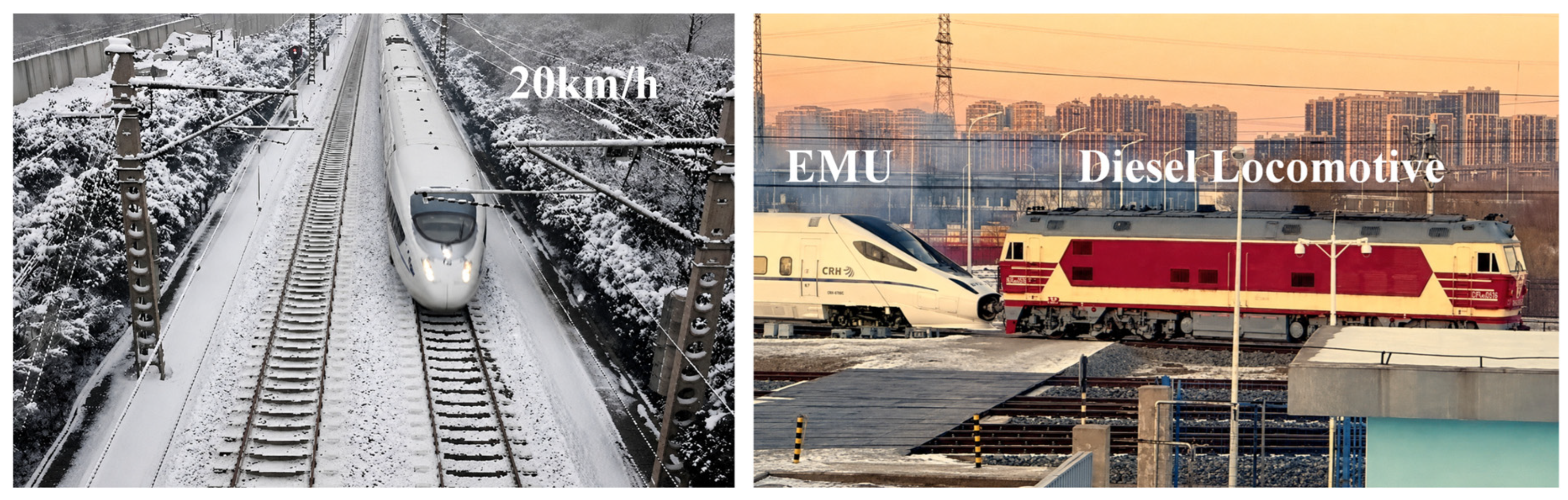
Distinct from other environmental factors, water can exist in three forms, gaseous, liquid, and solid, under different service conditions. It can also exist as a third-phase medium within the contact pair, thereby affecting current-carrying friction and wear characteristics [21,22,23]. In humid and rainy environments, due to the porous structure of the carbon contact strip material, water molecules adsorb onto the material’s surface and preferentially accumulate at surface asperities. This leads to a change in the lubrication state at the contact interface. Practical operating experience has shown that during rainfall, the carbon strip exhibits abnormal wear and frequent failures. Its wear rate can be several to dozens of times higher than under normal conditions. Wear at this accelerated rate may lead to increased replacement frequency and a sharp rise in maintenance costs [24] (shown in Figure 1b). However, compared to gaseous and liquid water environments, the hazards of icing conditions on the catenary system are more prominent, when the ambient temperature falls below 0 °C, water molecules undergo a phase change, and ice layers are prone to forming on the surface of the contact wire. As a third-phase medium on the contact interface, the ice layer significantly hinders current transmission, easily inducing electrical arcs, leading to deterioration of the pantograph–catenary electrical contact state [25]. In addition, during high-speed operation, irregular icing on the contact wire exerts a strong tangential impact on the pantograph strip. This impact causes severe pantograph–catenary vibration. In extreme cases, it can even lead to fracture of the carbon strip [26] (shown in Figure 1c). Such failures are highly destructive and pose a serious threat to the safe and stable operation of high-speed railways. Taking the Chinese Spring Festival travel rush from winter 2023 to 2024 as an example, 15 provinces including Northeast, North, Central, and East China experienced extreme icing weather such as ice, snow, and freezing rain. For example, freezing rain in Hubei caused severe icing of the overhead contact system, forcing a large number of trains to travel at a slow speed. Some areas even experienced power outages and were forced to use diesel locomotives to provide power (shown in Figure 2), which had a significant adverse impact on railway transport operations and passenger mobility.
Figure 2.
A typical situation of severe icing on the contact network in Hubei during the 2024 Spring Festival travel rush.
Against the backdrop of global climate change, extreme precipitation, freezing rain, and low-temperature icing events are becoming regionally more frequent and more intense, making the issues of rain/icing-induced disasters in high-speed railways increasingly prominent. Therefore, conducting research on the friction and wear behavior of PCSs under different phase states, revealing the inherent relationship between the damage of the third-phase medium and the current carrying friction pair materials, can help ensure the safe and stable operation of high-speed railways in water environments.
Based on the above research background, this paper conducts a literature review focusing on the “high-speed railway pantograph–catenary system—C/Cu contact pair—current-carrying friction and wear—icing/humidity/rainfall environments—response measures”. The research progress on current-carrying friction and wear of PCSs under icing conditions is comprehensively summarized. Taking water as a third-phase interfacial medium, this paper investigates the effects of water in different phase states on interfacial lubrication and arc ablation in pantograph–catenary systems and further reveals the interfacial damage mechanisms involving the participation of the third-phase medium. In view of the existing challenges, existing anti-icing and de-icing technologies are summarized, the current technical bottlenecks are identified, and future key research directions are discussed. This review provides theoretical guidance and technical support for further improving the wear resistance and safety of PCSs in icing environments.
2. Influence of Water Environments on Current-Carrying Friction for C/Cu Contact Pairs
2.1. Influence of Liquid Water (Rainfall) on Current-Carrying Friction for C/Cu Contact Pairs
Rainfall has a significant dual effect on C/Cu contact pairs. On the one hand, rainwater can reduce wear through cooling and lubrication, as well as by promoting the formation of oxide films. Matsuyama Shinsaku et al. simulated the operating conditions of a PCS in rainy weather by means of water spraying. They found that during current flow, the heat vaporizes the rainwater, carrying away a significant amount of Joule heat. This reduces the wear of the pantograph strip [27]. Jia Junhong et al. found that by dripping distilled water at a rate of 65–70 drops per minute onto the surface of copper graphite materials, the degree of material wear was reduced. This is due to the cooling effect of water, which leads to a decrease in surface temperature and is beneficial for reducing or inhibiting adhesion transfer [28].
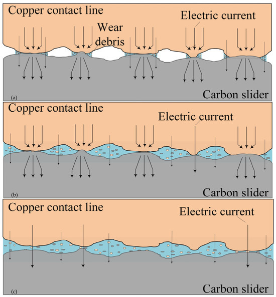
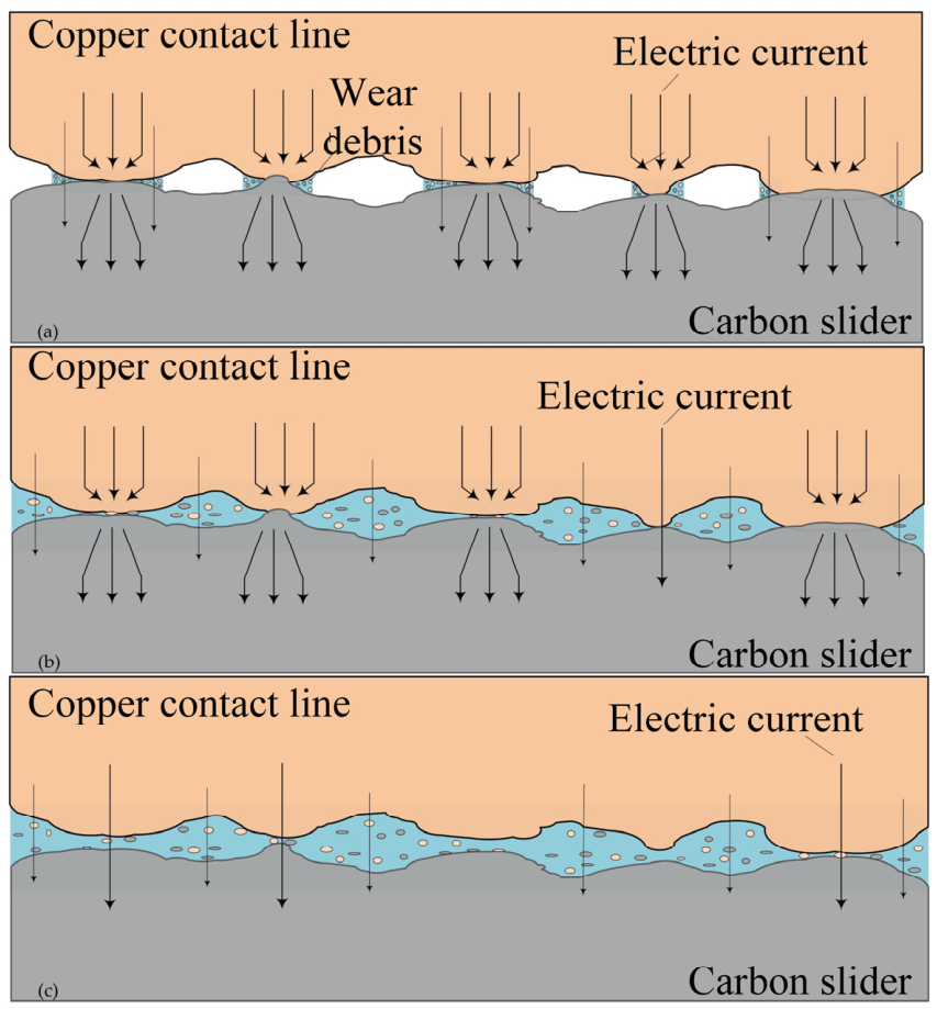
On the other hand, the water film formed by rainwater at the contact interface can reduce current collection stability, especially under high-current or high-rainfall conditions; the cooling and lubricating effects of rainwater are weakened, while arc ablation becomes more pronounced. Hu Daochun et al. pointed out that although water lubrication can reduce mechanical wear, it will increase arc ablation on the contact surface [29]. Wang et al. [30] used the immersion method and found that the addition of electric current would accelerate the failure of water lubrication and cooling effects, thereby exacerbating wear. Meanwhile, abnormal wear of the carbon strip occurs when the current exceeds 60 A, mainly due to the intensification of discharge erosion [31]. Gao et al. used the spray method to simulate actual rainfall conditions. The distribution of the interface water film with increasing rainfall levels is shown in Figure 3 [32]. They found that water preferentially accumulates on the roughness of the contact surface, forming a water film (shown in Figure 3a). When the rainfall is low, a very thin water film can be formed on the contact surface to protect the interface. At the same time, the number of current transmission channels increases, improving the current transmission capacity (shown in Figure 3b). However, when the water film is too thick, it will seriously hinder the conduction of current and deteriorate the quality of current collection (shown in Figure 3c). Especially under high-current conditions, the carbon strip experiences abnormal wear, accompanied by frequent arc discharge [33].
Figure 3.
Schematic diagram of interface water film distribution under different rainfall levels (a–c). Reproduced with permission from Ref. [31], Coatings 2022.
A rainfall environment can rapidly generate a visible water film or even localized water accumulation at the contact interface, thereby directly altering the real contact area, current conduction pathways, and interfacial thermal state. Under thin-water-film conditions, rainwater can provide certain cooling and lubricating effects, thus reducing mechanical wear. However, under thick-water-film and high-current conditions, the conductive pathways are prone to constriction, leading to increased contact resistance and arc energy, which further intensifies electrical discharge erosion and delamination wear. In addition, an increase in current further enhances the arc discharge effect.
2.2. Influence of Gaseous Water (Humidity) on Current-Carrying Friction for C/Cu Contact Pairs
The relative humidity method is mainly used to simulate high-humidity areas such as tunnels and coastal regions. The influence of humidity on strip wear is mainly reflected in the formation of surface oxide films and abrasive particles. As the number of water vapor molecules in the environment gradually increases, a more complete surface oxide film is formed, thereby lubricating and protecting the surface [34].
Zhou et al. found that under low humidity, the contact interface lacks sufficient adsorption of water molecules, causing the friction pair to approach a dry-friction state. As a result, the interfacial lubrication effect is weakened, while abrasive wear and arc ablation become more pronounced, leading to significant increases in both electrical and mechanical wear of the material and ultimately resulting in greater wear of the contact strip [35,36]. Moreover, the capillary force of water will cause the friction coefficient to increase with the increase in relative humidity and the contact resistance to increase with the increase in the spreading area of graphite on the contact surface [37].
Under moderate humidity conditions, water molecules in the air can lubricate contact surfaces, thereby reducing the friction coefficient between pairs and minimizing the detachment of strip materials [36]. Meanwhile, water vapor molecules help to reduce the surface energy of graphite, decrease the adhesion between contact areas, and reduce friction and wear. In addition, water molecules can act as a catalyst to facilitate the formation of a lubricating Cu2O protective layer, which protects the interface and reduces wear [38,39]. The water film attached to the contact pair improves the contact condition and enhances heat dissipation, resulting in lower arc energy and a smaller temperature rise in the pantograph strip compared to low-humidity environments. In light of the critical influence of humidity on wear, Zeng proposed optimizing operational parameters to mitigate strip wear. Specifically, to account for seasonal variations, pantograph pressure should be appropriately increased in high-humidity summer conditions, while train speed should be reduced during low-humidity winter periods [40].
When the humidity increases further, the effect of water molecules on the pantograph–catenary interface shifts from wear reduction to wear promotion. Ouyang et al. discovered that above 70% relative humidity, water molecules promote the formation of brittle compounds like Cu(OH)2 and Cu2(OH)2CO3. These compounds fracture readily, thereby hindering continuous lubricant film formation and accelerating abrasive wear [39]. In parallel, the passivation effect of water molecules enhances interlayer slip within the carbon, facilitating its delamination and transfer to the copper surface. This synergy causes a marked rise in carbon strip wear with increasing humidity [41]. Li et al. identified an optimal humidity of approximately 55% for minimizing adhesive wear in C/Cu friction pairs. Under this condition, the carbon contact strip also achieves stable electrical contact performance and low wear rates. However, under a high current, the influence of humidity on the friction coefficient weakens, and the increase in Joule heat and temperature makes it difficult to form a water film, disrupting the original balance and highlighting the wear phenomenon [42].
Additionally, the study by Li et al. shows that the cumulative arc energy and the average contact resistance are positively correlated with relative humidity [43]. Furthermore, due to arc ablation and splattered molten copper particles, the carbon surface is prone to the formation of ablation pits, exhibiting significant abrasive wear characteristics [44]. As the relative humidity increases, the duration of the arc will decrease. This is due to the increased thermal conductivity of air at higher relative humidity, which leads to increased cooling of the arc plasma and earlier arc collapse [45].
In summary, the effect of humidity can be summarized into three stages. First, under low-humidity conditions, insufficiently adsorbed water and protective surface films at the interface make adhesive wear and abrasive wear more likely to dominate. Second, under moderate-humidity conditions, an appropriate water film, carbon transfer film, and copper oxide film may act synergistically, thereby reducing mechanical damage and material delamination. Third, under excessively high-humidity or high-current conditions, a continuous water film may hinder the formation of stable conductive pathways and promote the generation of carbon layer peeling, causing arc ablation to become the dominant damage mode again.
In addition, the differences in humidity-dependent trends among different studies are not merely attributable to variations in the definitions of “high humidity” or “low humidity”. More importantly, factors such as material composition, sliding speed, contact pressure, and experimental geometry jointly alter the formation–breakdown equilibrium of the water film, thereby leading to transitions in the wear mechanisms.
2.3. Influence of Solid-Phase Water (Icing) on Current-Carrying Friction for C/Cu Contact Pairs
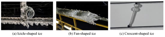
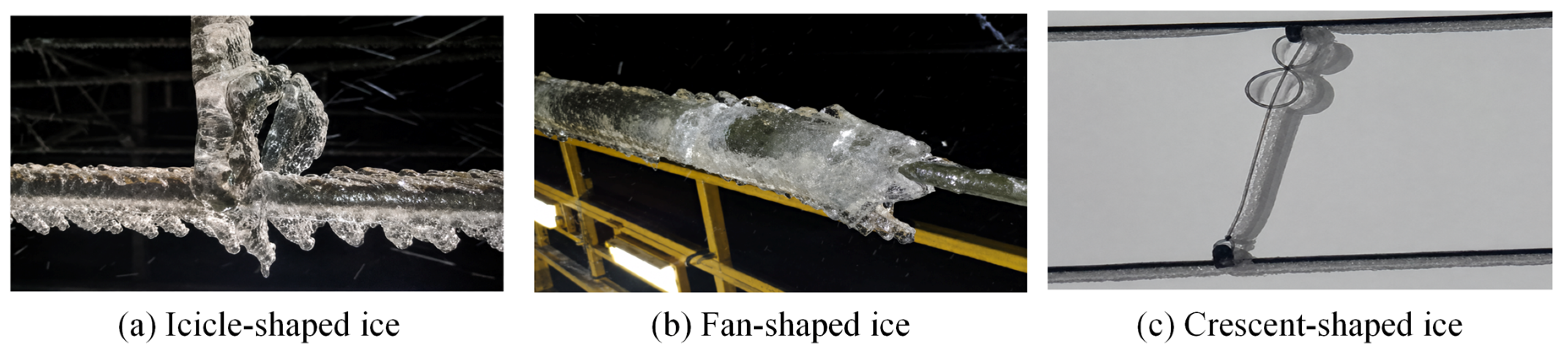
Icing is a natural physical phenomenon. It is highly dependent on ambient meteorological conditions, such as temperature, humidity, and wind speed. The main icing types include snow, hoarfrost, mixed rime, and glaze ice [46,47,48,49]. Table 1 presents the formation conditions and characteristics of different icing types. Among them, glaze ice cover is difficult to remove due to its high hardness and strong adhesion, making it the main type of ice cover that causes serious faults in overhead contact systems. Moreover, under the influence of environmental factors, ice accretion on overhead contact wires exhibits diverse morphologies, including irregular ice shapes such as crescent-shaped, icicle-shaped, and fan-shaped accretions (shown in Figure 4). These asymmetric icing morphologies can alter the local geometric profile of the contact wire, intensify impact and vibration during pantograph–catenary interaction, and further affect current collection stability.
Table 1.
Types and characteristics of catenary icing.
Figure 4.
Icing morphology of the overhead contact line.
According to a report by Bombardier in Sweden, the replacement number of carbon strips in winter is approximately 9–10 times that in summer [50]. At the same time, there is a significant seasonal difference in the proportion of mechanical wear and electrochemical wear of carbon strips. In winter, electrochemical wear is the main source, and the lower the temperature and the higher the humidity, the greater the proportion of electrochemical wear. In the Shenyang section of China, glaze ice accretion tends to form icicles on the contact wire, and electric locomotives often experience arc phenomena up to half a meter high when passing through. The wear of carbon strips far exceeds the annual cumulative wear under normal working conditions. Therefore, the PCS under icing conditions must be given high priority.
At present, there is relatively little research on the current-carrying friction and wear of PCSs under icing conditions. Existing studies have shown that icing on the catenary can alter its geometric morphology and stress state, thereby aggravating the wear of the contact strip and copper contact wire. Yao et al. pointed out that at low temperatures, the irregular ice layer formed on the surface of the contact wire will exacerbate the mechanical and electrical wear of the pantograph carbon strip. Especially at high train speeds, the thicker the ice layer, the lower the quality of current transmission in the PCS [51]. Li Zhihao found that low temperatures lead to decreased hardness in the contact materials. This reduction in hardness resulted in lamellar spalling on the carbon strip surface, accelerated wear, and the formation of severe ablation pits [52]. Shen et al. found that at low temperatures, the strong plowing action of copper on carbon materials reduces copper transfer, leading to increased wear of carbon materials. And the insulating effect of ice water at low temperatures slows down the occurrence of oxidation reactions [44]. Duan Fuchuan et al. found that when the thickness of the ice layer reaches 10 mm, the maximum contact pressure increases, making it easier to trigger fatigue damage along the contact line. This leads to excessive wear on the contact line and pantograph head, ultimately causing pantograph–catenary accidents [53].
At the same time, icing can reduce the stability of current transmission in the PCS, primarily because the electrical conductivity of ice is much lower than that of the copper contact wire. When the ice layer acts as a third-phase interfacial medium, it increases the contact resistance and induces pronounced fluctuations, thereby increasing the risk of contact loss and pantograph–catenary arcing. Related studies have shown that, under icing conditions, the hazards of pantograph–catenary arcs and their electromagnetic interference effects become more pronounced [54]. Li Yunda and Xing Licheng found that a thicker ice layer on the contact surface leads to a higher probability of pantograph–catenary arcing, with accompanying arc ablation to both the contact wire and carbon strip becoming increasingly severe [55,56]. Guo et al. studied the thermal effect of electric arcs on contact wire ice layers. They found that electric arcs cannot completely melt the ice layer, but under icing conditions, the thermal erosion of the contact wire by electric arcs is more severe [57].
The primary wear mechanisms and interfacial evolution behaviors of the C/Cu contact pair under dry, humid, rainfall, and icing conditions are summarized in Table 2.
Table 2.
Mechanisms of action under different water-phase environments.
3. Response Measures
In PCSs, good interfacial contact is essential for ensuring a stable energy supply to trains. However, as discussed in Section 2, water in different phase states, especially under icing conditions, can significantly deteriorate the interfacial state of C/Cu contact pairs. This may induce contact resistance fluctuations, contact loss and arcing, and mechanical impact damage, thereby threatening the safe and stable operation of high-speed railways. Therefore, to minimize the operational risks of high-speed railways in different water-phase environments, numerous scholars have conducted a series of studies. At present, the response measures mainly include speed limit operations and anti-icing/de-icing technologies. The ultimate goal is to restore and maintain a relatively “healthy” tribological interface of the PCS, thereby ensuring the safe and stable operation of trains.
3.1. Speed Limit
Rainfall will reduce visibility, especially when the hourly rainfall reaches the standard level of rainstorm, and the view outside the vehicle is severely limited, which seriously affects the normal operation. Therefore, based on the impact of rainfall on the operation of high-speed railways, China State Railway Group Co., Ltd. has established corresponding defense levels (shown in Table 3). And according to the regulations of Japan’s Shinkansen, when the hourly precipitation exceeds 25 mm, trains are required to enter a state of vigilance; when hourly precipitation reaches 40–45 mm, train speed must be limited to 170 km/h [58].
Table 3.
Classification of the impact of rainfall (1 h rainfall R) on the operation of high-speed railways.
The impact of freezing rain on high-speed railway operations is primarily assessed by the diameter of ice accumulation on power lines (with a bare wire diameter of 26.8 mm), as shown in Table 4 [59]. However, the applicable scope of this speed restriction standard remains insufficiently defined. Therefore, Yang et al. proposed a contact line icing system model and found that when the ice layer thickness is too large and the train speed is too high, the quality of current transmission will significantly decrease. Based on this, they also determined the maximum allowable ice thickness for the overhead contact system at different train speeds: when the train speed is 350 km/h, 330 km/h, 280 km/h, and 260 km/h, the maximum allowable ice thickness for the overhead contact system is 4 mm, 8 mm, 12 mm, and 16 mm, respectively [60].
Table 4.
Classification of impact of freezing rain (wire icing diameter D) on high-speed railway operation.
3.2. Anti-Icing/De-Icing Technology
Although speed-limited operation can alleviate icing-induced damage to the interface to some extent, it is a typical passive control measure and cannot fundamentally eliminate the influence of ice accretion on the PCS. Moreover, under extreme icing disasters, relying solely on speed-limited operation not only makes it difficult to ensure the rapid recovery of the catenary state, but also significantly reduces line transportation efficiency. Therefore, the development of efficient and reliable catenary anti-icing/de-icing technologies is an important approach to improving the safety and resilience of high-speed railway operation in winter. Existing catenary anti-icing/de-icing technologies can generally be classified into three categories: mechanical de-icing, electrothermal de-icing, and active anti-icing. To clarify the applicability boundaries and engineering limitations of different technologies, this section comprehensively reviews these technologies from three aspects: action mechanisms, engineering applicability, and key limitations.
- (1)
- Mechanical De-Icing
Mechanical de-icing is currently one of the most widely used and relatively straightforward de-icing methods in railway field applications. It mainly relies on external impact, scraping, or vibration to disrupt the adhesion between the ice layer and the contact wire, causing the ice layer to crack, detach, and fall off.
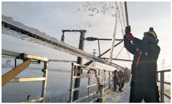
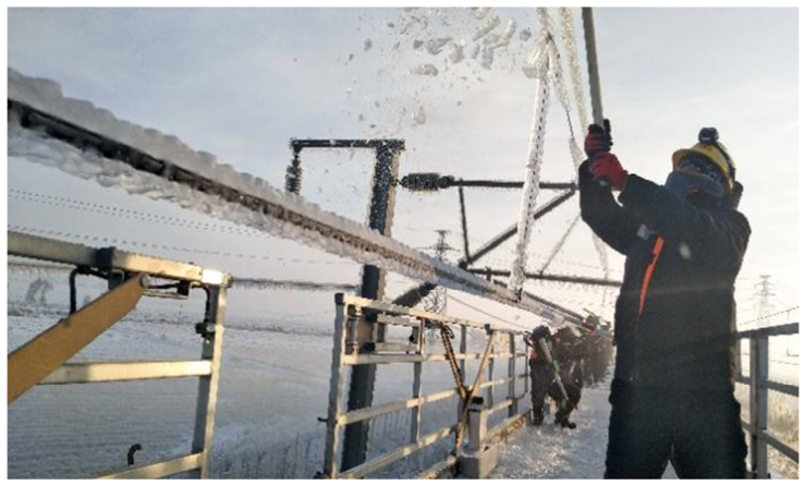
Currently, railway departments commonly adopt manual de-icing methods to address icing on contact lines [61,62] (shown in Figure 5). Workers apply impact and prying force to ice-covered sections using tools such as crowbars and hammers, causing the ice layer to fracture, detach, and fall off. Although this method is simple and direct, it requires a large amount of manpower, and the de-icing process is time-consuming, inefficient, and poses a high safety risk. Especially under extreme ice disasters, secondary icing on the catenary system evolves at an extremely rapid rate. Manual de-icing can hardly keep pace with ice accumulation, leading to a short-lived de-icing effect and exposing workers to high-risk operating conditions. Therefore, this method is only applicable to short-distance lines with light icing.
Figure 5.
Manual de-icing M = method.
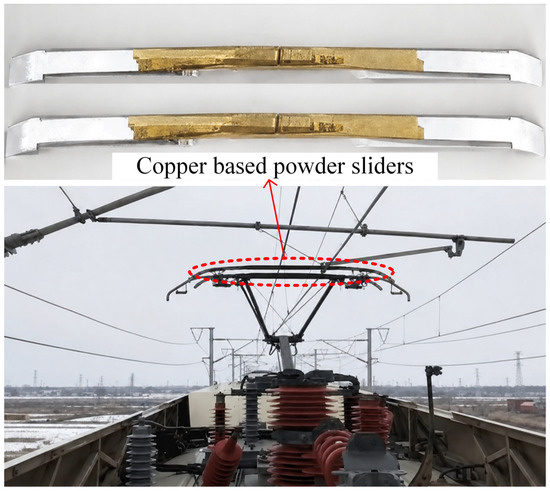
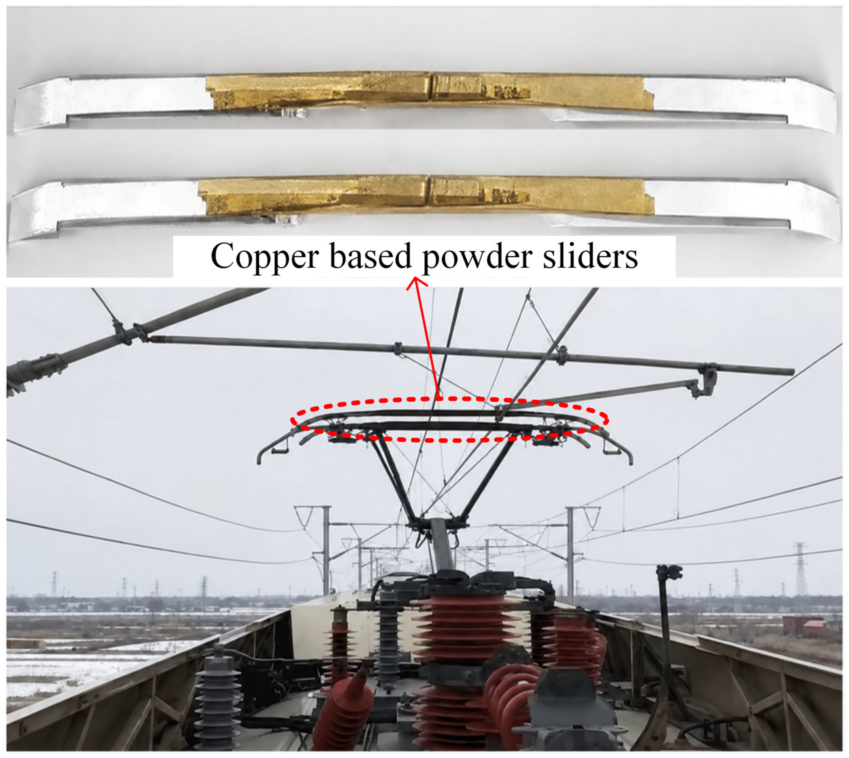
The hot-sliding de-icing method is another mechanical de-icing approach with practical engineering applications, typically used when ice accretion on the catenary reaches a certain thickness. This method uses copper-based pantograph strips (shown in Figure 6), fully utilizing their high mechanical strength and impact resistance. They slide along the contact network through an inertial operation mode, and use the friction between the pantograph strip and the contact wire to achieve mechanical scraping of icing [63]. At present, this method has been widely applied on multiple lines, such as the Hanyi Line and the Hewu Line. Field experience demonstrates that it has good de-icing effects under moderate-to-mild icing conditions. However, when encountering glazed icing with strong adhesion, its de-icing efficiency significantly decreases. Additionally, if parameters are not properly controlled, it may cause a certain degree of mechanical damage to the contact wire. Consequently, these drawbacks limit the engineering application of this technology in large-scale, strongly adhesive icing scenarios.
Figure 6.
Hot-sliding de-icing method.
In addition, to improve the de-icing efficiency and adaptability of mechanical de-icing technologies, recent studies have introduced vibration de-icing methods, which reduce the adhesion strength of the ice layer and promote its detachment by adjusting the vibration frequency, amplitude, and loading position. Based on an Ansys finite element model, Gao Xiaojie conducted a simulation of the de-icing process via contact network vibration under impact loading. The results revealed that applying a step load is more conducive to de-icing under identical conditions, thereby validating the effectiveness of mechanical vibration de-icing [64]. Wu Lei et al. further revealed the influence of vibration parameters on de-icing effectiveness. Their research found that the loading point, load magnitude, and ice thickness all impact the de-icing result, leading to the identification of the optimal loading pattern [65]. This further expands the applicability of mechanical de-icing.
- (2)
- Electrothermal De-Icing
Electrothermal de-icing technology uses Joule heating generated by current on the contact network impedance to heat the wire and melt the ice coating [66]. It can be specifically divided into DC de-icing and AC de-icing.
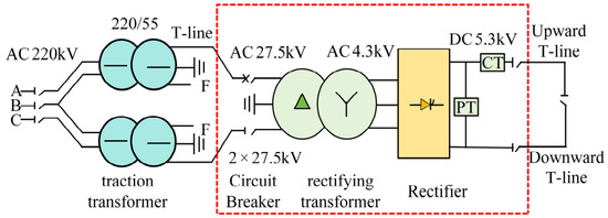
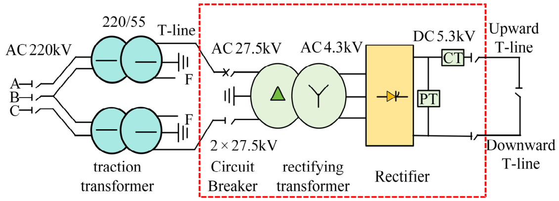
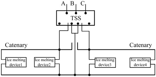
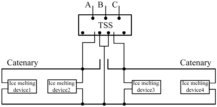
DC de-icing adopts the short-circuit method to connect the upstream and downstream power supply arms, forming a closed circuit (shown in Figure 7). Based on the 27.5 kV AC power output from the transformer in the traction substation, it is converted into DC power through a DC de-icing device to achieve de-icing [67]. However, traditional DC devices have problems such as a large volume, high harmonic content, and low utilization rate during operation. Therefore, Ban proposed a control method for a modular multilevel DC de-icing device based on SVG. This control method can not only achieve highly reliable DC de-icing for ice-covered lines but also provide dynamic reactive power compensation, stabilize grid voltage, and significantly improve the utilization rate of the device [68]. Jing Huabing proposed a method that employs cascaded power units to elevate the output voltage and utilizes IGBT-based multi-quadrant rectification. This enables effective rectification while enhancing the grid-side power quality. And the output voltage of the ice melting current is stable, the input harmonic content is low, and it has little impact on the power grid, which can be effectively applied to engineering practice [69].
Figure 7.
DC de-icing technology for overhead contact lines. Reproduced with permission from Ref. [66], J. China Railw. Soc. 2025.
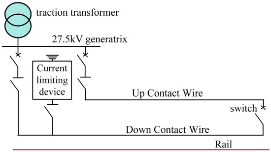
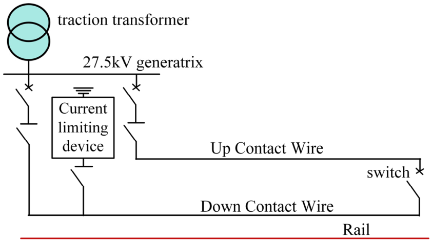
AC de-icing utilizes AC power sources with voltage levels below 35 kV in substations, and a melting circuit is formed by connecting upstream and downstream contact lines in series. We can adjust the impedance of the melting circuit as needed, control the short-circuit current on the contact wire within the allowable range, and make the ice melt and fall off (shown in Figure 8). Li Gang discovered that the resistor current-limiting solution can not only achieve offline ice melting but also enable online ice prevention while ensuring the safe operation of the locomotive, without reducing the power factor. It is an ideal ice melting solution [70]. In the late 20th century, McCurdy J D proposed the high-frequency ice melting method. This technique utilizes the dielectric heating effect of ice under a high-frequency alternating electric field to generate heat directly, while the strong skin effect causes the current to concentrate on the surface of the wire, preventing heat loss inside the wire. Xiong Qiang found that the high-frequency ice melting method has higher energy utilization efficiency than the traditional AC short-circuit method, and its critical current is relatively small and the ice melting time is short [71].
Figure 8.
AC de-icing technology for overhead contact lines. Reproduced with permission from Ref. [66], J. China Railw. Soc. 2025.
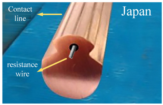
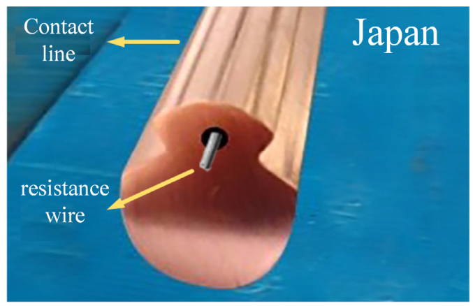
In addition, Japan proposed a method of embedding heating wires inside the contact wire for de-icing (shown in Figure 9). By leveraging the high-resistance characteristic of the built-in heating wires, heat is generated by applying current to them, thereby achieving the ice melting effect. However, this method faces challenges such as high manufacturing costs, limited practical effectiveness, and difficult maintenance.
Figure 9.
Japanese built-in resistance wire de-icing.
- (3)
- Anti-Icing Technology
Compared to de-icing techniques, the most ideal approach to solve the problem of icing on the overhead contact system is anti-icing. This method aims to prevent ice formation by disrupting the conditions required for ice accumulation, thereby achieving the goal of maintaining ice-free conditions. At present, effective anti-icing methods mainly include electric thermal anti-icing, chemical agents, and material coating anti-icing.
Electrothermal anti-icing can be regarded as an earlier-stage application of electrothermal de-icing technology in which a critical current is applied before or during the initial stage of ice accretion to keep the contact wire surface temperature above 0 °C. This disrupts the conditions required for ice formation on the catenary and thereby prevents icing [72] (shown in Figure 10). Li Qunzhan proposed a power-frequency online anti-icing scheme for the electrified railway based on SVG. By regulating the SVG, the current in the contact wire is increased to prevent ice formation. This system can provide sufficient anti-icing current without stopping and ensure the stability of the traction network voltage [73,74,75]. Fritjof et al. proposed an anti-icing method based on resistance heating. The heating coefficient can more accurately predict the temperature changes of the contact network, avoiding damage to the contact network components caused by excessive or insufficient current [76].
Figure 10.
Principle of anti-icing using reactive current. Reproduced with permission from Ref. [66], J. China Railw. Soc. 2025.
The Fraunhofer Institute in Germany has successfully implemented the chemical agent method on work vehicles. This technique primarily utilizes a spraying device installed on the pantograph to apply an anti-icing agent onto the contact wire, thereby preventing ice accumulation on it. However, due to frequent friction between the PCS, the anti-icing coating is easily damaged and has limited timeliness. At the same time, chemical agents can also cause pollution to the surrounding population and environment. Therefore, this method is more suitable as a localized, short-term auxiliary measure than as a primary solution for long-term catenary anti-icing [77].
Anti-icing technology mainly utilizes low-surface-energy or high-lubricity anti-icing materials to reduce the adhesion strength of the object surface, delay the icing time, and thus reduce the adhesion of ice layers. At present, most anti-icing coatings use hydrophobic materials, which usually do not have good conductivity. Therefore, they may seriously affect the energy transmission efficiency of the PCS and be difficult to apply. However, in recent years, carbon fibers and carbon nanomaterials have shown broad application prospects in the field of anti-icing due to their excellent conductivity, thermal conductivity, and good compatibility with composite materials [78]. Raji et al. developed an epoxy resin coating material filled with graphene nanoribbons and applied it to helicopter rotor blades. The study found that at −20 °C with a power density of 0.5 W/cm2, this coating could effectively remove ice layers with a thickness of 1 cm [79], and at the same time, an input power of 0.3 kW/m2 can achieve effective anti-icing at −15 °C [80]. Yao et al. prepared highly ordered carbon nanotube (CNT) mesh electrothermal components using a spinning method, conferring the advantages of rapid heating and uniform temperature distribution. In the de-icing test, a laminated board containing 40 layers of CNT mesh was able to remove surface ice within 15 s at an input power of 4.9 kW/m2 [81].
However, during train operation, the frequent sliding contact between the pantograph and the contact wire surface caused the anti-icing coating to be easily damaged, making it difficult to sustain the anti-icing effect. Therefore, we developed a composite strip material based on carbon fiber/carbon nanotubes, so that the carbon powder transferred during the friction process rapidly heats up when electrified, maintaining the contact wire surface temperature above 0 °C and achieving anti-icing. This phenomenon indicates that developing carbon-based composite contact strip materials with integrated electrical conductivity, wear resistance, and anti-icing functionality may be more engineering-feasible than directly applying anti-icing coatings to the contact wire. In numerous studies on carbon contact strip materials for high-speed railways, carbon fibers and carbon nanomaterials have been widely employed to enhance the electrical conductivity, thermal conductivity, mechanical strength, and wear resistance of carbon contact strips [82,83]. Although carbon fibers and carbon nanomaterials exhibit excellent properties, their smooth surfaces, chemical inertness, and the presence of organic binders in surface coatings may lead to poor interfacial bonding with the carbon matrix, thereby adversely affecting the performance of the resulting composites [84]. To solve the interface bonding problem, Li et al. introduced carbon nanotubes and nano carbon black into the carbon matrix through electrostatic self-assembly, forming a synergistic network. This not only improved the mechanical properties of the composite material, but also effectively enhanced its thermal conductivity [85]. Zhao Yang et al. investigated pre-oxidized carbon fiber (OPF)-reinforced pantograph carbon strip material and found that the incorporation of OPF enhanced the electrical conductivity, thermal conductivity, and mechanical properties of the strip material, with the thermal conductivity coefficient increasing by 21.22% [86]. Although this technology has not yet been applied on site, its potential in high-speed railway anti-icing systems is enormous and it is expected to become an important candidate direction for catenary anti-icing and contact strip material optimization in the future.
- (4)
- Hybrid De-Icing Methods
The aforementioned anti-icing/de-icing techniques can effectively address contact wire icing issues. But in emergency situations, especially when faced with high hardness and strong adhesion of glaze ice, standalone de-icing methods often struggle to meet the demand for efficient ice removal. Moreover, completely eliminating the ice layer typically requires significantly more energy consumption, which may lead to unnecessary damage. For example, although electrothermal de-icing can effectively melt ice, it has high energy consumption, a long melting time, and may lead to a loss of electrical connection components; mechanical de-icing can directly remove ice layers, but its efficiency is relatively low, and improper operation may damage the contact wire. In view of this, more and more scholars are exploring the combination of various de-icing technologies, fully leveraging their respective advantages to achieve efficient, fast, and reliable de-icing effects.
In the field of transmission lines, Zhou Chao proposed a hybrid de-icing technology combining thermal melting and mechanical de-icing. The results demonstrate that this technology reduces de-icing time to only 10–20% of that required by standalone thermal melting, while the critical impact force is merely about 40% of that needed in pure mechanical de-icing. This approach not only significantly shortens de-icing time but also effectively prevents conductor damage and residual ice accumulation [87]. In the field of wind turbine blades, Shen et al. proposed a hybrid de-icing method combining electro-thermal and ultrasonic technologies. The study found that this approach significantly reduces energy consumption and peak temperature while allowing for optimal de-icing efficiency under different working conditions by adjusting the power ratio [88]. In the field of road de-icing, Zhou et al. integrated hot-water jetting with mechanical grinding to develop a multifunctional hybrid de-icing system. The hot-water jetting cuts the ice layer into smaller sections, while the mechanical grinding rapidly removes the residual ice, significantly enhancing the overall de-icing efficiency [89].
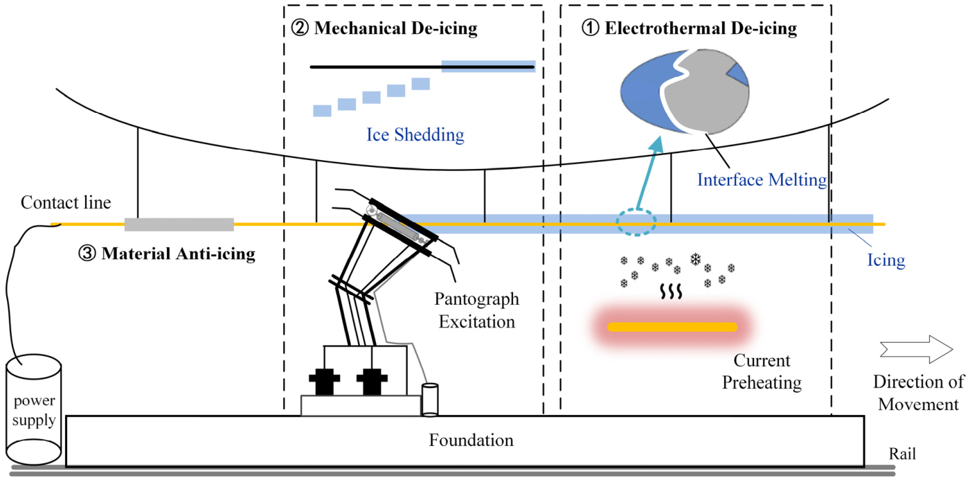
Drawing on successful experiences with hybrid de-icing technologies from other fields, future research on anti-icing/de-icing of high-speed railway catenaries could further develop efficient de-icing strategies based on the synergistic effects of electrical, mechanical, and material approaches. Through the sequential coordination of different physical mechanisms, the adhesion strength and failure threshold of ice layers can be reduced. The specific concept is as follows: ① Apply a de-icing current to effectively disrupt the strong adhesion between the conductor and the ice layer. ② Utilize a de-icing method with multi-frequency vibration excitation to achieve rapid detachment of the ice layer from the contact wire surface. ③ Spray an anti-icing coating onto the contact wire surface to prevent secondary adhesion of the ice layer. Through this synergistic de-icing technology, efficient de-icing of the contact wire is achieved, significantly saving time. This is the most ideal de-icing technology for the future (shown in Figure 11).
Figure 11.
Coupled de-icing design diagram.
- (5)
- Comparison of de-icing technologies
In summary, different anti-icing/de-icing technologies have distinct characteristics in terms of their mechanisms of action, energy utilization methods, engineering applicability, and operating conditions. To facilitate a comprehensive comparison of the technical features of these methods, the main advantages, limitations, and applicable scenarios of the aforementioned anti-icing/de-icing technologies are summarized in Table 5.
Table 5.
Performance comparison of different anti-icing/de-icing technologies.
4. Conclusions and Future Prospects
This paper reviews the current-carrying friction and wear behavior of C/Cu contact pairs in PCSs under water environments. The influences of three typical aqueous conditions (humidity, rainfall, and icing) on interfacial lubrication, current transmission, and arc ablation behavior are primarily analyzed, and existing anti-icing/de-icing technologies and their engineering applicability are summarized. The main conclusions are as follows:
- (1)
- The influence of humidity can be summarized into three stages. Under low-humidity conditions, insufficient interfacial lubrication leads to pronounced abrasive wear and arc ablation. Moderate humidity is conducive to the formation of adsorbed water films and oxide films, thereby reducing friction and wear. However, excessively high humidity may disrupt the stable oxide film and induce fluctuations in contact resistance, resulting in aggravated wear once again.
- (2)
- Under rainfall conditions, a relatively thin water film can provide certain cooling and lubrication effects, thereby reducing mechanical wear. However, when the water film becomes excessively thick, the conductive pathways tend to constrict, leading to increased contact resistance and arc energy, which further aggravates arc ablation and delamination wear. In addition, an increase in current further intensifies arc discharge.
- (3)
- Icing conditions pose the most prominent hazard to the PCS. The ice layer not only significantly accelerates the wear of the pantograph strip but also compromises the electrical conductivity of the contact pair, increasing the inter-electrode resistance, which leads to frequent arcing. Irregular ice layers can also introduce additional mechanical impacts, exacerbating pantograph–catenary vibrations. In severe cases, this may result in failure issues such as carbon strip fracture.
- (4)
- Existing countermeasures include speed limit operations, mechanical de-icing, electrothermal de-icing, chemical agent anti-icing, and material-based anti-icing. However, a single technology can hardly satisfy multiple requirements simultaneously, such as de-icing efficiency, energy consumption control, and protection against contact wire damage.
Although the aforementioned research findings have achieved certain results in engineering applications, the following issues still urgently need to be resolved: Traditional pantograph strip materials face difficulty in withstanding long-term service in this environment. In addition, under extreme ice cover disasters, manual de-icing methods are still mainly relied upon, making it difficult to meet the demand for large-scale and efficient de-icing. Therefore, based on the above content, the following prospects are proposed for as urgent research that needs to be carried out in this field in the future:
- (1)
- New carbon strip material: In response to problems such as insufficient wear resistance, weak resistance to arc ablation, and the poor impact resistance of carbon strips under complex aqueous environments, including humidity, rainfall, and low-temperature icing, future research should be conducted on novel carbon-based composite strip materials with high wear resistance, strong ablation resistance, and excellent low-temperature impact resistance. Particular attention should be paid to optimizing material composition, reinforcement distribution, and electrical and thermal conductivity. Meanwhile, predictive models for the service life of pantograph strips under aqueous environments should be established.
- (2)
- Ice monitoring technology: Considering the diverse types, complex states, and significant dynamic evolution of catenary icing, high-precision online monitoring technologies with strong anti-interference capability should be developed in the future. These technologies should enable the comprehensive sensing of icing type, thickness, mass, and contour morphology. By integrating meteorological information and pantograph–catenary dynamic response data, models for icing risk identification, severity assessment, and early warning should be established, thereby providing a basis for train speed-restricted operation, dispatching organization, and active anti-icing/de-icing decision-making.
- (3)
- Efficient de-icing technology: In view of the limitations of single de-icing technologies in terms of de-icing efficiency, energy consumption control, contact wire damage, and the prevention of secondary icing, a multi-mode synergistic anti-icing/de-icing technology system should be developed in the future. By leveraging the advantages of different de-icing technologies, integrated control of icing identification, active de-icing, effectiveness evaluation, and secondary icing prevention can be achieved, thereby enabling efficient ice removal and improving the operational reliability of PCSs under icing conditions.
Therefore, it is urgent to address these existing issues one by one to ensure the secure and stable operation of high-speed railways, thereby reducing potential operational risks and economic losses.
Author Contributions
Q.W.: writing—original draft. G.G. and H.W.: methodology, funding acquisition. Z.L.: data curation, supervision. J.C.: project administration. G.W.: investigation. T.L.: conceptualization. J.H. and G.H.: software, visualization. P.Q. and B.T.: investigation, validation. All authors have read and agreed to the published version of the manuscript.
Funding
This work was funded by the Innovation Research Group Project of Natural Science Foundation of Sichuan (2024NSFTD0009), the Youth Science and Technology Foundation of Gansu (No. 23JRRA828).
Data Availability Statement
Please add the corresponding content of this part.
Acknowledgments
This research was supported by the following the Science and Technology Project, The Innovation Research Group Project of Natural Science Foundation of Sichuan (2024NSFTD0009), and The Youth Science and Technology Foundation of Gansu (No. 23JRRA828).
Conflicts of Interest
The authors declare that they have no known competing financial interests or personal relationships that could have appeared to influence the work reported in this paper.
References
- Wu, G.N.; Dong, K.L.; Xu, Z.L.; Xiao, S.; Wei, W.; Chen, H.; Li, J.; Huang, Z.; Li, J.; Gao, G.; et al. Pantograph–catenary electrical contact system of high-speed railways: Recent progress, challenges, and outlooks. Railw. Eng. Sci. 2022, 30, 437–467. [Google Scholar] [CrossRef] [Scilit]
- Gao, G.Q.; Qian, P.Y.; Xu, Z.L.; Dong, K.; Wang, Q.; Peng, W.; Liu, Y.; Ma, Y.; Xiao, S.; Huang, G.; et al. The evolution law of the pantograph–catenary arc with the multi-stress coupled force analysis under the sub-atmospheric pressure strong-airflow condition. Phys. Plasmas 2022, 30, 437–467. [Google Scholar] [CrossRef] [Scilit]
- Gao, G.Q.; Wang, Q.S.; He, Z.J.; Wang, H. Influence of Interface Oxidation on the Electrical Contact Properties of C-Cu Contact Pairs. Proc. CSEE 2023, 43, 8502–8511. [Google Scholar] [CrossRef]
- Zuo, H.Z.; Wei, W.F.; Yang, Z.F.; Li, X.; Xie, W.; Liao, Q.; Xian, Y.; Ren, J.; Gao, G.; Wu, G. Synchronously improved mechanical strength and electrical conductivity of Carbon/Copper composites by forming Fe3C interlayer at C/Cu interface. Mater. Today Commun. 2021, 28, 102661. [Google Scholar] [CrossRef] [Scilit]
- Bucca, G.; Collina, A. A procedure for the wear prediction of collector strip and contact wire in pantograph-catenary system. Wear 2009, 266, 46–59. [Google Scholar] [CrossRef] [Scilit]
- Midya, S.; Bormann, D.; Schutte, T.; Thottappillil, R. Pantograph Arcing in Electrified Railways-Mechanism and Influ-ence of Various Parameters: Part II: With AC TractionPower Supply. IEEE Trans. Power Deliv. 2009, 24, 1940–1950. [Google Scholar] [CrossRef] [Scilit]
- Xu, Z.L.; Gao, G.Q.; Wei, W.F.; Yang, Z.; Xie, W.; Dong, K.; Ma, Y.; Yang, Y.; Wu, G. Characteristics of pantograph-catenary arc under low air pressure and strong airflow. High Volt. 2022, 7, 369–381. [Google Scholar] [CrossRef] [Scilit]
- Qian, P.Y.; Gao, G.Q.; Dong, K.L.; Wang, Q.; Peng, W.; Ma, Y.; Zhou, C.; Chen, S.; Yang, Z.; Xiao, S.; et al. Research on driving force and dynamic characteristics of pantograph–catenary arc. J. Phys. D Appl. Phys. 2023, 56, 412505. [Google Scholar] [CrossRef] [Scilit]
- Wang, H.; Gao, G.Q.; Wei, W.F.; Yang, Z.; Yin, G.; Xie, W.; He, Z.; Ni, Z.; Yang, Y.; Wu, G. Influence of the interface temperature on the damage morphology and material transfer of C–Cu sliding contact under different current amplitudes. Mater. Sci. 2022, 57, 5006–5021. [Google Scholar] [CrossRef] [Scilit]
- Wu, G.N.; Wu, J.; Wei, W.F.; Zhou, Y.; Yang, Z.; Gao, G. Characteristics of the sliding electric contact of pantograph/contact wire systems in electric railways. Energies 2017, 11, 17. [Google Scholar] [CrossRef] [Scilit]
- Yang, H.J.; Chen, G.X.; Gao, G.Q.; Wu, G.; Zhang, W. Experimental research on the friction and wear properties of a contact strip of a pantograph–catenary system at the sliding speed of 350 km/h with electric current. Wear 2015, 332, 949–955. [Google Scholar] [CrossRef] [Scilit]
- Yin, J.; Zhang, H.B.; Xiong, X.; Tao, H.; Wang, P.; Deng, C. Influence of applied load on wear behavior of C/C-Cu composites under electric current. Prog. Nat. Sci. Mater. Int. 2017, 27, 192–196. [Google Scholar] [CrossRef] [Scilit]
- Zheng, R.G.; Liu, X.M. Effect of load and velocity on wear behaviour of Cu based self-lubricating composite. Mater. Res. Innov. 2014, 18, S2-S12–S2-S15. [Google Scholar] [CrossRef] [Scilit]
- Ding, T.; Chen, G.X.; Wang, X.; Zhu, M.; Zhang, W.; Zhou, W. Friction and wear behavior of pure carbon strip sliding against copper contact wire under AC passage at high speeds. Tribol. Int. 2011, 44, 437–444. [Google Scholar] [CrossRef] [Scilit]
- Bouchoucha, A.; Chekroud, S.; Paulmier, D. Influence of the electrical sliding speed on friction and wear processes in an electrical contact copper-stainless steel. Appl. Surf. Sci. 2004, 223, 330–342. [Google Scholar] [CrossRef] [Scilit]
- Lancaster, J.K. A review of the influence of environmental humidity and water on friction, lubrication and wear. Tribol. Int. 1990, 23, 371–389. [Google Scholar] [CrossRef] [Scilit]
- Wang, H.; Gao, G.Q.; Lei, D.; Wang, Q.; Xiao, S.; Xie, Y.; Xu, Z.; Ma, Y.; Dong, K.; Chen, Q.; et al. Influence of interface temperature on the electric contact characteristics of a C-Cu sliding system. Coatings 2022, 127, 1713. [Google Scholar] [CrossRef] [Scilit]
- Zhan, H.; Wang, R.J.; Li, Z.D. Friction and Wear Properties of Functional Films on Ti Alloy Surface under Salt Spray Corrosion Conditions. Surf. Technol. 2018, 47, 109–115. [Google Scholar] [CrossRef]
- Wang, P.F.; Adachi, K. Effect of oxygen concentration in inert gas environments on friction and wear of carbon nitride coatings. Tribol. Online 2011, 6, 265–272. [Google Scholar] [CrossRef] [Scilit]
- Huang, S.Y.; Feng, Y.; Liu, H.J.; Ding, K.; Qian, G. Electrical Sliding Friction and Wear Properties of Cu-MoS2-graphite-WS2 Nanotubes Composites in Air and Vacuum Conditions. Mater. Sci. Eng. A 2013, 560, 685–692. [Google Scholar] [CrossRef] [Scilit]
- Sun, Y.X.; Song, C.F.; Liu, Z.L.; Li, J.; Sun, Y.; Shangguan, B.; Zhang, Y. Effect of relative humidity on the tribological/conductive properties of Cu/Cu rolling contact pairs. Wear 2019, 436, 203023. [Google Scholar] [CrossRef] [Scilit]
- Sun, Y.X.; Song, C.F.; Liu, Z.L.; Li, J.; Wang, L.; Sun, C.; Zhang, Y. Tribological and conductive behavior of Cu/Cu rolling current-carrying pairs in a water environment. Tribol. Int. 2020, 143, 106055. [Google Scholar] [CrossRef] [Scilit]
- Liu, X.L.; Li, Z.H.; Hu, M.J.; Zhou, C.W.; Xiao, Q.; Yang, W.B.; Chen, D.Y. Research on the wear properties of carbon strips and contact wires at frigid temperatures. Wear 2021, 486, 204122. [Google Scholar] [CrossRef] [Scilit]
- Wang, X. Study on the Effect of Water on the Friction and Wear Performance of the Carbon/Metal Contact Pair with Electric Current. Master’s Thesis, Southwest Jiaotong University, Chengdu, China, 2021. [Google Scholar] [CrossRef]
- Zhang, H.; Wei, W.F.; Pan, L.K.; Yang, Z.; Huang, G.; Liu, Y.; Chen, X.; Yang, Z.; Wu, G. Ice-covered environmental adaptability assessment for overhead contact system in high-speed railways. Chin. J. Electr. Eng. 2024, 10, 70–79. [Google Scholar] [CrossRef] [Scilit]
- Na, K.M.; Lee, K.; Shin, S.K.; Kim, H. Detecting deformation on pantograph contact strip of railway vehicle on image processing and deep learning. Appl. Sci. 2020, 10, 8509. [Google Scholar] [CrossRef] [Scilit]
- Matsuyama, S.; Li, C.Y. Tribology of Pantograph Current Collection. Control. Inf. Technol. 1997, 1, 52–60. [Google Scholar] [CrossRef]
- Jia, J.H.; Zhou, H.D.; Wang, J.B.; Zhou, H.; Chen, J.M. A Comparative lnvestigation of the Tribological Behavior and Wear Mechanism of Bronze-graphite Composite under Dry- and Water-lubricated Sliding against Steel. Tribology 2002, 1, 36–39. [Google Scholar] [CrossRef] [PubMed]
- Hu, D.C.; Sun, L.; Shangguan, B. Tribological Characteristics of T2/QCr0.5 Rubbing Pairs under Electric Current with and without Water. Lubr. Eng. 2007, 32, 105–107. [Google Scholar]
- Wang, X.; Yang, Z.F.; Gao, G.Q.; Wang, H.; Deng, L.; Wei, W.F. Effect of wet condition on the wear performance of carbon strip and metal contact wire with electric current. In Proceedings of the 2020 IEEE International Conference on High Voltage Engineering and Application (ICHVE), Beijing, China, 6–10 September 2020; pp. 1–4. [Google Scholar] [CrossRef] [Scilit]
- Wang, H.; Gao, G.Q.; Deng, L.; Li, X.; Wang, X.; Wang, Q.; Wu, G. Study on Current-Carrying Tribological Characteristics of C-Cu sliding electric contacts under different water content. Coatings 2022, 13, 42. [Google Scholar] [CrossRef] [Scilit]
- Gao, G.Q.; Wang, Q.S.; Wang, H.; Qian, P.; Peng, W.; Ma, Y.; Dong, D.; Wang, X.; He, S.; Yang, Z.; et al. Study on current-carrying tribological characteristics of C-Cu sliding electric contacts under water accumulation from rainfall condition. Phys. Scr. 2024, 99, 055970. [Google Scholar] [CrossRef] [Scilit]
- Wang, M.; Guo, F.Y.; Wang, Z.Y.; Chen, Z.H.; Xue, Y.M. Study on the Wear Characteristics of Slide PlateUnder Wet Conditions. High Volt. Appar. 2018, 54, 292–296. [Google Scholar] [CrossRef]
- Huang, M.; Yang, B.; Rong, Y.X.; Zhao, L.; Xiao, S. Study on friction and wear properties of copper-impregnated carbon slide plate under different humidity conditions. Tribol. Trans. 2023, 66, 953–964. [Google Scholar] [CrossRef] [Scilit]
- Zhi, X.S.; Zhou, N.; Cheng, Y.; Wang, X.; Wei, H.; Chen, G.; Zhang, W. Effect and behaviors of ambient humidity on the wear of metal-impregnated carbon strip in pantograph-catenary system. Tribol. Int. 2023, 188, 108864. [Google Scholar] [CrossRef] [Scilit]
- Hua, H.; Liu, S.N.; Chen, G.X.; Tang, Y.; Zhang, J.C.; Chang, Y. Experimental Study on Friction and Wear Properties of Pantograph-Catenary Systems under High and Low Humidity Conditions. Machinery 2024, 51, 30–36. [Google Scholar] [CrossRef]
- Wang, X.X.; Xin, S.; Wu, R.X.; Wang, Q.; Shao, X.H.; Tian, Z.Q.; Wu, X.; Song, C.F. Study on Current-carrying Tribological Properties of Copper/Carbon Pairs in Different Relative Humidity. J. Henan Univ. Sci. Technol. (Nat. Sci.) 2022, 43, 9–13+4–5. [Google Scholar] [CrossRef]
- Hu, Z.L.; Chen, Z.H.; Xia, J.T. Study on surface film in the wear of electrographite brushes against copper commutators for variable current and humidity. Wear 2008, 264, 11–17. [Google Scholar] [CrossRef] [Scilit]
- Ouyang, H.B.; Wang, P.; Li, C.Y.; Gao, R.; Shen, T.; Li, Y. Effect of humidity on the friction and wear behavior of C/C-CuNi composites. Diam. Relat. Mater. 2024, 146, 111144. [Google Scholar] [CrossRef] [Scilit]
- Zeng, Z.Y.; He, Q.X.; Chen, G.X.; Zhao, P.P.; Dong, B.J. Influence of Environment Humidity on Wear and Temperature Rise ofMetal-impregnated Carbon Strip. Lubr. Eng. 2024, 49, 98–105. [Google Scholar] [CrossRef]
- Wu, R.X.; Song, C.F.; Wu, H.H.; Lv, B.; Zhang, Y.; Zhang, Y. Effect of relative humidity on the current-carrying tribological properties of Cu–C sliding contact pairs. Wear 2022, 492, 204219. [Google Scholar] [CrossRef] [Scilit]
- He, K.X.; Guan, J.F.; Han, F.; Wu, J.Q. Effect of Air Humidity on Slide Plate Wear and Temperature Rise. Electr. Rail. 2023, 34, 61–63. [Google Scholar] [CrossRef]
- Li, H.X.; Ji, D.H.; Shen, M.X.; Xiao, Y.L.; Zhao, H.P.; Liu, X.L.; Xiong, G.Y. Effect of Environmental Humidity on Tribological Behavior of Carbon/Copper Current-Carrying Sliding Contact Pairs. Tribology 2022, 42, 709–718. [Google Scholar] [CrossRef]
- Shen, M.X.; Ji, D.H.; Hu, Q.; Xiao, L.; Li, Q. Current-carrying tribological behavior of C/Cu contact pairs in extreme temperature and humidity environments for railway catenary systems. Sci. China Technol. 2024, 67, 2537–2548. [Google Scholar] [CrossRef] [Scilit]
- Danny, S.; Mark, S.; David, T.W.P.; Greedy, S. The Effects of Relative Humidity on DC Series Arc Generation and Detection. In Proceedings of the 2023 IEEE Energy Conversion Congress and Exposition (ECCE), Nashville, TN, USA, 29 October–2 November 2023; pp. 5700–5707. [Google Scholar] [CrossRef] [Scilit]
- Li, Z.; Huang, G.Z.; Wu, G.N.; Gao, G.; Yang, Z.; Zhu, H.; Gan, G. Prediction model for icing growth characteristics of high-speed railway contact lines. Cold Reg. Sci. Technol. 2024, 227, 104306. [Google Scholar] [CrossRef] [Scilit]
- Makkonen, L. A Model of Hoarfrost Formation on a Cable. Cold Reg. Sci. Technol. 2013, 85, 256–260. [Google Scholar] [CrossRef] [Scilit]
- Makkonen, L. Models for the Growth of Rime, Glaze, Icicles and Wet Snow on Structures. Philos. Trans. R. Soc. Lond. Ser. A Math. Phys. Eng. Sci. 2000, 358, 2913–2939. [Google Scholar] [CrossRef] [Scilit]
- Karakose, E.; Gencoglu, M.; Karakose, M.; Aydin, I.; Akin, E. A new experimental approach using image processing based tracking for an efficient fault diagnosis in pantograph-catenary systems. IEEE Trans. Ind. Inform. 2016, 13, 635–643. [Google Scholar] [CrossRef] [Scilit]
- Rong, Y.X.; Huang, M.; Zhao, L.; Zhang, S.Q.; Lv, K.; Liao, Z.; Xiao, S.N.; Yang, B. Microscopic Study on Abnormal Wear Characteristics of Subway Pantograph Carbon Strip in Winter. Coatings 2023, 48, 7–14. [Google Scholar] [CrossRef]
- Yao, Y.M.; Zhou, N.; Mei, G.M.; Zhang, W. Dynamic Analysis of Pantograph-Catenary System considering Ice Coating. Shock. Vib. 2020, 2020, 8887609. [Google Scholar] [CrossRef] [Scilit]
- Li, Z.H. Research on the Wear Properties of Carbon Strips and Contact Wires at Frigid and Alternative Temperatures. Master’s Thesis, East China Jiaotong University, Nanchang, China, 2022. [Google Scholar] [CrossRef]
- Duan, F.C.; Liu, Z.G.; Song, Y.; Zhang, J. Influences of lce Load and Air Damping on Dynamic Current Collection of Pantograph-lced Catenary. J. Southwest Jiaotong Univ. 2016, 51, 177–187. [Google Scholar] [CrossRef]
- Surajit, M.; Dierk, B.; Thorsten, S.; Thottappillil, R. DC Component From Pantograph Arcing in AC Traction System-InfluencingParameters, Impact, and Mitigation Techniques. IEEE Trans. Electromagn. Compat. 2011, 53, 18–27. [Google Scholar] [CrossRef] [Scilit]
- Li, Y.L. Study on the Influence of Pantograph-Carenary Arc on Ice Cover Catenary. Master’s Thesis, Southwest Jiaotong University, Chengdu, China, 2017. [Google Scholar]
- Xing, L.C. Erosion Mechanism of Pantograph Arc and the Influence of Environmental Variables on Erosion. Master’s Thesis, Beijing Jiaotong University, Beijing, China, 2020. [Google Scholar] [CrossRef]
- Guo, L.; Li, Y.L.; Yang, J.; Yu, W. Thermal field analysis of icing contact line under the effect of pantograph-catenary system arc. In Proceedings of the 2016 IEEE International Conference on Power System Technology (POWERCON), Wollongong, Australia, 28 September–1 October 2016; pp. 1–6. [Google Scholar] [CrossRef] [Scilit]
- GB/T 28592-2012; Grade of Precipitation. China Standards Press: Beijing, China, 2012.
- QX/T 59-2007; Specifications for Surface Meteorological Observation Part15: Measurement of Wire Icing. China Meteorological Press: Beijing, China, 2007.
- Yang, Z.F.; Yang, Z.Q.; Huang, G.Z.; Chen, X.; Ma, T.; Zhang, H.; Wei, W.; Wu, G. Effect of ice-covered catenary on dynamic interactions of pantograph-catenary system and limited speed of trains. Cold Reg. Sci. Technol. 2024, 228, 104331. [Google Scholar] [CrossRef] [Scilit]
- Pohlman, J.C.; Landers, P. Present State-of-the-Art of Transmission Line Icing. IEEE Trans. Power Appar. Syst. 1982, PER-2, 2443–2450. [Google Scholar] [CrossRef] [Scilit]
- Li, Z.; Huang, G.Z.; Zhang, Z.J.; Liu, Y.; Gao, G.; Yang, G.; Yang, X.; Wu, G. Review of Catenary Icing on High-Speed Railways: Characteristics, Impact and Countermeasures. High Volt. 2026. [Google Scholar] [CrossRef] [Scilit]
- Chen, J.H.; Cheng, F.; Huang, G.Z.; He, S.H.; Li, Z.; Gao, G.Q. Research Progress on De-icing Technology for High-speed Railway Catenary Systems. J. Electr. Eng. 2025, 20, 452–464. [Google Scholar] [CrossRef]
- Gao, X.J. Study on Impact of Mechanical Vibration to Catenary Icing. Master’s Thesis, Southwest Jiaotong University, Chengdu, China, 2016. [Google Scholar]
- Wu, L.; Xu, M.N.; Zhang, H.P.; Wu, W.; Ding, J.M. Simulation Analysis of lmpact Vibration De-icing forOverhead Catenary of Electrified Railway. J. China Railw. Soc. 2025, 47, 47–53. [Google Scholar] [CrossRef]
- Wu, G.N.; Wang, M.; Guo, Y.J.; Xiao, G.; Zhang, X.Q. Ice Melting Mechanism and Key Technologies for High-speedRailway Contact Networks: A Systematic Review. J. China Railw. Soc. 2025, 47, 40–53. [Google Scholar] [CrossRef]
- Cinieri, E.; Fumi, A. Deicing of the contact lines of the high-speed electric railways: Deicing configurations. Experimental test results. IEEE Trans. Power Del. 2014, 29, 2580–2587. [Google Scholar] [CrossRef] [Scilit]
- Ban, G.B.; Niu, W.; Zhang, L.S.; Yang, W.Y.; Li, J.W.; Ma, X.T. SVG control function and realization of modular multi-level DC ice melting device. In Proceedings of the 2021 IEEE 16th Conference on Industrial Electronics and Applications (ICIEA), Chengdu, China, 1–4 August 2021; pp. 1261–1266. [Google Scholar] [CrossRef] [Scilit]
- Jing, H.B.; Nian, X.H. Catenary Dc lce-Melting Technology and Device Development of Electrified Railway. Trans. China Electrotech. Soc. 2012, 27, 277–284. [Google Scholar] [CrossRef]
- Huang, W.X. Research on Main Electromagnetic Characteristics of New Type Ice-Melting Method in Electrified Railway. Railw. Stand. Des. 2012, 4, 120–123. [Google Scholar] [CrossRef]
- Xiong, Q. Research on Transmission Line De-icing Based on Skin Effect and Dielectric loss. Master’s Thesis, Changsha University of Science & Technology, Changsha, China, 2018. [Google Scholar]
- Guo, L.; Zhou, L.J.; Chen, M.W.; Huang, W. Online catenary anti-icing technique for electric railways employing direct feeding systems. IET Gener. Transm. Distrib. 2016, 10, 1969–1975. [Google Scholar] [CrossRef] [Scilit]
- Li, Q.Z.; Guo, L.; Shu, Z.L.; Yi, D. Online Antiicing Technology for Catenary of Electrified Railway. J. China Railw. Soc. 2013, 35, 46–51. [Google Scholar] [CrossRef]
- Guo, L.; Gao, X.J.; Li, Q.Z.; Huang, W.; Shu, Z. Online antiicing technique for the catenary of the high-speed electric railway. IEEE Trans. Power Del. 2014, 30, 1569–1576. [Google Scholar] [CrossRef] [Scilit]
- Guo, L.; Li, Q.Z.; Xie, S.F.; Shu, Z.L. Temperature Field of Catenary for Electrified Railway during Online Anti-icing. J. Southwest Jiaotong Univ. 2013, 48, 230–235+242. [Google Scholar] [CrossRef]
- Nilsson, F.; Moyassari, A.; Bautista, A.; Castro, A.; Arbeloa, I.; Järn, M.; Lundgren, U.; Welinder, J.; Johansson, K. Modelling anti-icing of railway overhead catenary wires by resistive heating. Int. J. Heat Mass Transf. 2019, 143, 118505. [Google Scholar] [CrossRef] [Scilit]
- Wang, H.R.; Liu, Z.G.; Song, Y.; Lu, X.; Han, Z.; Zhang, J.; Wang, Y. Detection of contact wire irregularities using a quadratic time–frequency representation of the pantograph–catenary contact force. IEEE Trans. Instrum. Meas. 2016, 65, 1385–1397. [Google Scholar] [CrossRef] [Scilit]
- Ying, Y.X.; Lu, H.D.; Yang, Q.M.; Wang , Q.; Si, Y.; Feng, Y.; Wang, W.D.; Yao, X.D. Advances in electrothermal anti-icing and de-icing technigues for aircraft. Acta Mater. Compos. Sin. 2025, 1–23. [Google Scholar] [CrossRef]
- Raji, A.; Varadhachary, T.; Nan, K.W.; Wang, T.; Lin, J.; Ji, Y.; Genorio, B.; Zhu, Y.; Kittrell, C.; Tour, J.M. Composites of graphene nanoribbon stacks and epoxy for joule heating and deicing of surfaces. ACS Appl. Mater. Interfaces 2016, 8, 3551–3556. [Google Scholar] [CrossRef] [Scilit] [PubMed]
- Zhang, Q.Q.; Yu, Y.K.; Yang, K.C.; Zhang, B.; Zhao, K.; Xiong, G.; Zhang, X. Mechanically robust and electrically conductive graphene-paper/glass-fibers/epoxy composites for stimuli-responsive sensors and Joule heating deicers. Carbon 2017, 124, 296–307. [Google Scholar] [CrossRef] [Scilit]
- Ya, X.; Falzon, B.G.; Hawkins, S.C.; Tsantzalis, S. Aligned carbon nanotube webs embedded in a composite laminate: A route towards a highly tunable electro-thermal system. Carbon 2018, 129, 486–494. [Google Scholar] [CrossRef] [Scilit]
- Monfaerd, J.S.; Okan, B.S.; Menceloglu, Y.Z.; Yildiz, M. Nano-engineered design and manufacturing of high-performance epoxy matrix composites with carbon fiber/selectively integrated graphene as multi-scale reinforcements. RSC Adv. 2016, 6, 9495–9506. [Google Scholar] [CrossRef] [Scilit]
- Kubota, Y.; Peng, H.M. A basic study on the application of C/C composite pantograph contact strip to Shinkansen vehicle. Foreign Locomot. Roll. Stock Technol. 2018, 5, 21–26. [Google Scholar] [CrossRef] [Scilit]
- Li, Y.L.; Kinloch, I.; Windle, A. Direct spinning of carbon nanotube fibers from chemical vapor deposition synthesis. Science 2004, 304, 276–278. [Google Scholar] [CrossRef] [Scilit] [PubMed]
- Li, J.; Li, H.; Gao, G.Q.; Yang, Z.; Lin, J.; Huang, X.; Zhao, Y.; Chen, Q.; Wei, W.; Wu, G. Improving the performance of carbon/graphite composites through the synergistic effect of electrostatic self-assembled carbon nanotubes and nano carbon black. Ceram. Int. 2022, 48, 36029–36037. [Google Scholar] [CrossRef] [Scilit]
- Zhao, Y.; Li, J.; Yang, Z.F.; Gao, G.Q.; Wei, W.F.; Wu, G.N. Study on Pre-Oxidized Carbon Fiber Reinforced Pantograph Carbon Slide Plates. J. China Railw. Soc. 2024, 46, 56–64. [Google Scholar] [CrossRef]
- Zhou, C.; Ren, J.; Ji, K.P.; Li, J.H.; Li, L. Rapid de-icing method for transmission line combining initial ice melting and impaet de-icing. J. Tsinghua Univ. (Sci. Technol.) 2026, 66, 577–585. [Google Scholar] [CrossRef]
- Shen, H.; Zhang, F.P.; Guo, W.F.; Xu, Z.; Li, Y. An experimental study on surface de-icing of glass fiber-reinforced plastic plate by electrothermal and ultrasonic coupling method. Appl. Therm. Eng. 2025, 265, 125570. [Google Scholar] [CrossRef] [Scilit]
- Zhou, J.Z.; Xu, X.P.; Chu, W.J.; Dai, J.Y.; Chen, Y.H.; Zhu, Z.C.; Lai, S.W. R&D of a New De-Icing Device Based on Synthetically De-Icing Techniques. Appl. Mech. Mater. 2013, 372, 381–386. [Google Scholar] [CrossRef] [Scilit]

Disclaimer/Publisher’s Note: The statements, opinions and data contained in all publications are solely those of the individual author(s) and contributor(s) and not of MDPI and/or the editor(s). MDPI and/or the editor(s) disclaim responsibility for any injury to people or property resulting from any ideas, methods, instructions or products referred to in the content. |
© 2026 by the authors. Licensee MDPI, Basel, Switzerland. This article is an open access article distributed under the terms and conditions of the Creative Commons Attribution (CC BY) license.