


Abstract
Plain bearings are widely used in heavy-duty applications, e.g., wind turbine drivetrains or ship propulsion systems. Plain bearings offer high load-carrying capacity and good damping, but abnormal events such as oil supply failure (OSF) can rapidly damage the bearing and cause failure of the entire drivetrain. An adequate oil supply is essential for the operation of the plain bearing. A failure of the oil supply can cause fatal failure of the bearing due to adhesive wear within a matter of seconds. Existing condition monitoring systems (CMS) for plain bearings generally cannot detect OSF in time, or require costly and complex installation, limiting their practical applicability. This paper presents temperature field measurement (TFM) as a simple, low-cost CMS approach for early OSF detection. The results presented within this work demonstrate that TFM detects the onset of OSF within 30 s of oil supply interruption, at least 30 s before a rise in friction torque can be detected in the corresponding test bearing. The findings demonstrate that TFM is a valid, simple, and effective method for the timely detection of OSF, offering a practical alternative to existing CMS approaches for heavy-duty plain bearing applications.
1. Introduction
Unexpected bearing failures are a major root cause of machine downtimes. For example, in combustion engines of ship propulsion systems, main engine plain bearing failure causing crankshaft damage is the largest repair cost factor [1]. Investigations regarding main engine claims reveal that bearing-related damage to the crankshaft is the costliest failure. The cost of crankshaft damage in main engines of ship propulsion systems is an average of US $1.37 million per claim [2]. In automotive applications, hydrodynamic plain bearings also play an essential role. Insufficient lubrication of the crankshaft plain bearings can lead to a total failure of the internal combustion engine [3,4]. In order for plain bearings to perform their primary function of transmitting motion and forces, an adequate supply of lubricating oil is essential [5]. Spontaneous failure of bearings can be caused, for example, by failure of the oil supply. As the plain bearing gradually runs dry, the dominant wear mechanism shifts from abrasion to severe adhesion, eventually causing bearing failure [6]. The frictional heat generated causes thermal expansion of the shaft in contact with the plain bearing. The thermal expansion of the shaft can progress to the point where the bearing clearance ψ is completely eliminated [7]. Ultimately, localized adhesive bonds between the bearing and shaft surfaces accumulate and grow, progressively closing the running clearance until the bearing seizes, making further operation of the drive system impossible. The resulting damage pattern due to insufficient lubrication is characterized by blue and black discoloration on the bearing and shaft, as well as material transfer [8]. In the event of spontaneous failure, there is very little time to act between the initial onset of damage and the failure of the bearing [9].
Utilizing CMS can be a valid option to detect OSF in the operation of a plain bearing at an early stage. For hydrodynamic plain bearings, a variety of condition monitoring methods, such as lubricant outlet temperature, vibration, or oil condition monitoring, are well established [10]. However, these methods typically react too slowly to reliably detect oil supply failure (OSF) in time to prevent damage. Measurement principles suitable for plain bearings also include high-frequency acoustic methods (e.g., Acoustic Emission (AE) [11,12,13]) or inductive displacement sensors for determining the lubrication gap height [10]. For the detection of OSF in plain bearings, high-frequency acoustic methods were the primary focus of experimental investigations in research [14,15,16,17]. However, the aforementioned monitoring methods are associated with high costs and complex data analysis due to the large amount of measurement data generated [18]. Furthermore, available CMS are usually retrofitted to the plain bearings and require external wiring for data transmission as well as power supply [18,19]. In multi-axis rotating systems, such as planetary plain bearings, engine crankshaft bearings or difficult-to-access locations, cable routing can be very complex.
Temperature field measurement (TFM) represents a novel monitoring approach for plain bearings. Originally, this approach was developed to determine the lubrication gap height based on measuring the temperature field of the bearing under steady-state conditions. Compared to other CMS systems for plain bearings, the TFM approach stands out for its low cost, simple data processing, and low energy consumption [20]. The energy requirement is three orders of magnitude lower than alternatives [20]. Therefore, the energy demand of the TFM-based CMS can be permanently met through thermoelectric energy harvesting, utilizing the heat generated by friction in the plain bearing during operation. Measuring data are processed by a microcontroller integrated into the plain bearing and transmitted wirelessly. The developed CMS is thus capable of operating autarkically without external cabling for power supply or data transmission. In contrast, AE- and vibration-based methods generate large volumes of high-frequency data that require complex signal processing and external wiring for power and data transmission. In addition, continuous measurement utilizing AE is often not possible due to the large amount of data that is generated. Lubricant-temperature monitoring, on the other hand, is often measured at the oil outlet, as specified in DIN 31652-3 [21], which results in a long transfer path and corresponding latencies in detecting temperature changes due to a changing friction state within the bearing.
The TFM approach has been shown to work reliably under steady-state conditions [19,20]. For spontaneous failures, however, where a rapid transient temperature rise is expected, the sensitivity of the TFM approach to detect such changes in time has not yet been demonstrated. The main novelty of this work lies in demonstrating, for the first time, that a spatially resolved TFM-based CMS can detect the onset of OSF. This detection occurs significantly earlier than a rise in friction torque, i.e., before severe, damage-critical mixed friction occurs. Compared with acoustic emission- and vibration-based approaches, the TFM-based CMS offers a simplicity and cost advantage. The approach is also highly energy efficient. This allows for autarkic operation using energy harvesting methods. However, the focus of the present work will be on qualifying TFM for early detection of OSF. To be useful for early warning, the TFM approach must detect and transmit data several seconds before a fatal bearing failure occurs. In this work, this capability is investigated using OSF as a representative rapid, spontaneous failure-inducing event.
For this purpose, TFM-based characteristics for OSF detection are first determined for a plain bearing with an inner diameter size of di = 120 mm. The CMS concept is then applied to a smaller size, di = 30 mm, and the defined TFM characteristics for OSF detection are validated. The downscale step addresses the challenge of sensor miniaturization. Furthermore the downscaling accounts for the fact that smaller bearings, due to their lower thermal mass, are expected to heat up more rapidly under OSF conditions, resulting in faster failure progression. It will be shown that the TFM approach detects critical events multiple seconds before bearing failure occurs and that the derived indicators can be used across several bearing geometries. Furthermore, it will be shown that TFM-based characteristics for early damage detection are applicable to different bearing geometries.
2. Materials and Methods
The following section provides a brief explanation of the underlying concept of temperature field-based condition monitoring for plain bearings. Subsequently, the two prototypes for conducting the temperature field measurement and the microelectronic components used are described. Finally, the test rig setups are outlined, in which the CMS concept is validated for detecting OSF.
2.1. Temperature Field Measurement—Fundamentals
The initial idea of TFM-based CMS originates from determining the lubrication gap height based on the Gümbel curve. However, the Gümbel curve is only valid for steady-state conditions and cannot detect mixed friction. However, once the lubricant film falls below the threshold hlim marking the transition to mixed friction, contact between roughness peaks causes solid-body friction resulting in local temperature rises. A spatially resolved temperature field measurement (TFM) is therefore well suited to rapidly detecting this fluid-to-mixed-friction transition [22]. To ensure maximum sensor sensitivity to changing friction conditions, the thermal connection between sensor and bearing must be optimized, and the distance to the friction location minimized—particularly since, per DIN 31692-2, temperature sensors must not be integrated directly into the lubrication gap [23]. Incipient damage to the plain bearing is accompanied by high heat input into the bearing and could be detected by selecting appropriate temperature-based thresholds via in situ TFM. Whether rapidly progressing bearing damage caused by OSF can be detected early using TFM has so far only been examined simulatively via TEHD (thermoelastohydrodynamic) simulation in [22]. In [22], it was demonstrated simulatively that OSF-induced local temperature increases in the plain bearing beneath the running surface can be detected by temperature sensors before mixed friction sets in. Experimental verification has not yet been conducted.
2.2. Temperature Field Measurement—Setup
The implementation of the prototypes is based on the fundamental principles of sensor-integrating machine elements (SiME) defined by Kirchner et al. [18]. According to the requirements derived from Kirchner’s SiME definition, the sensors are fully integrated into the plain bearing volume. Only commercially available, cost-effective, and energy-efficient microelectronic components are used. A microcontroller with a Bluetooth wireless module is integrated into the bearing on the PCB. Thermogenerators are installed on the front of the bearing to generate energy, enabling fully autarkic operation. Ref. [22] provides a comprehensive overview of the concept behind the developed sensor-integrating plain bearing (SiPB). However, this paper focuses primarily on the temperature field-based condition monitoring approach. Although data transmission and energy harvesting are implemented in the prototype for autarkic operation, they fall outside the scope of this publication.
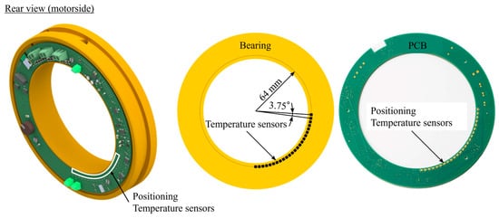
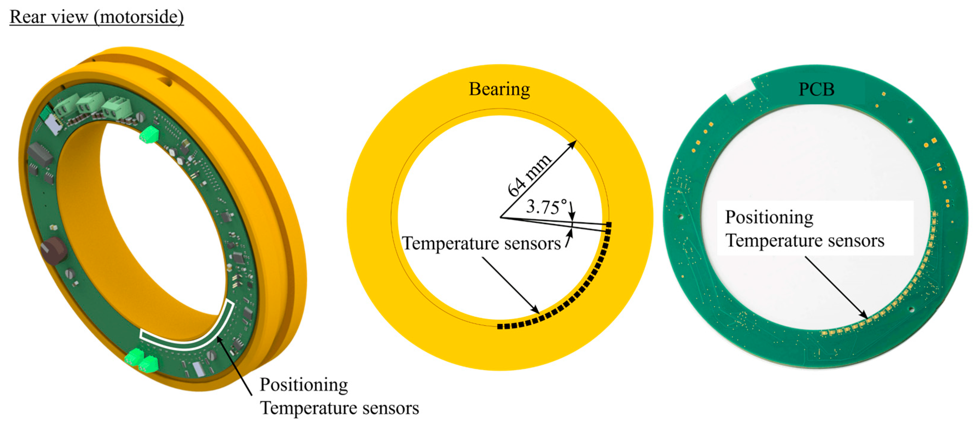
The temperature sensors used for TFM are positioned within the plain bearing volume in accordance with the preliminary design described in [19,20]. The bearing angle range φ = 180–270° was defined as the temperature field relevant for measurement. Since the test rig can only accommodate rotation in one direction, the quadrant in which the shaft displacement takes place is equipped with sensors. Figure 1 displays the sensor positions on the printed circuit board (PCB) integrated into the bearing.
Figure 1.
Prototype 120 mm: Temperature sensor positioning.
The “TMP117” digital temperature sensor by Texas Instruments [24] is used to develop the prototype for the larger prototype size (GLP120). The “TMP117” sensor is characterized by its energy efficiency, high measurement accuracy, and compact size compared to analog temperature sensors. The temperature sensor has a square base with an edge length of 2.1 mm and a height of 0.8 mm. The sensors are placed on the PCB with their centers at a radius of R = 64 mm measured from the center of the bearing. The minimum distance between the temperature sensors and the bearing running track is therefore 2.95 mm. The radius was selected to minimize the sensor’s distance to the running surface while preserving the mechanical integrity of the machine element, which is affected by the insertion of the circuit PCB sensors and the necessary connections to the PCB; a minimum angular spacing of ∆φ = 3.75° can be achieved. A low angular resolution is not possible, because otherwise the sensor positions would overlap. A total of 24 temperature sensors are placed on the PCB, with the position φ = 270° left vacant. The sensor’s continuously permissible measurement range is TA = −55–150 °C. The measurement accuracy over the entire permissible measurement range is ∆TMeas = ± 0.1 °C and therefore far more accurate compared to analog sensors [25]. Additionally, digital sensors offer the advantage of automatic calibration at the start of every experiment over analog sensors.
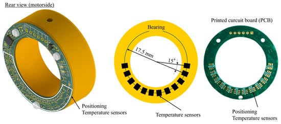
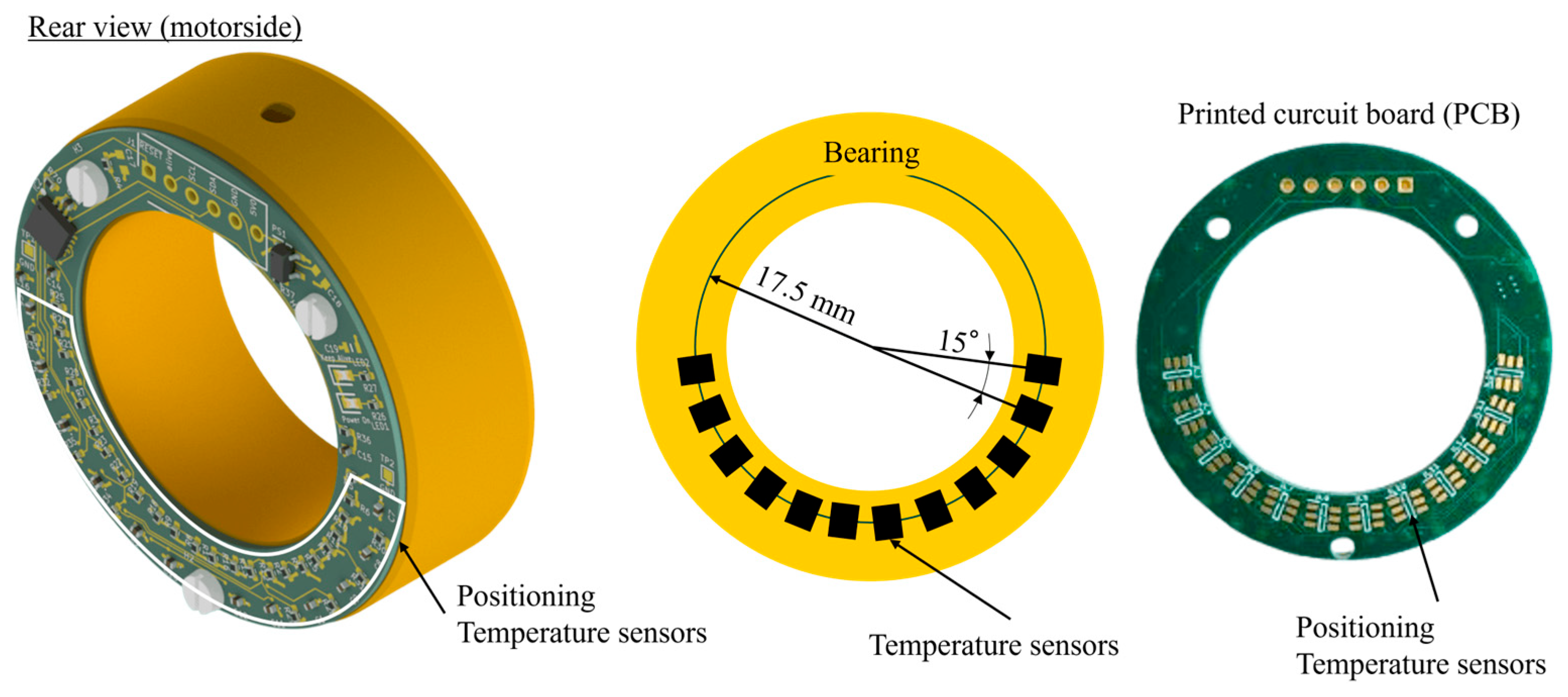
Subsequently, the configuration of the TFM setup for the smaller bearing size is described. Figure 2 depicts the sensor positions for the TFM-CMS for the GLP30 test bearing.
Figure 2.
Prototype 30 mm: Temperature sensor positioning.
A total of 12 temperature sensors is placed on the PCB. On the GLP30 test rig, whose design is described in Section 2.3, only one direction of shaft rotation is implemented, resulting in a shaft displacement in only one quadrant for steady-state operation. Due to the minimum achievable angular resolution of ∆φ = 15° for the GLP30 bearing size, the lower half of the bearing shell was equipped with temperature sensors. The first temperature sensor is placed at an angular position of φ = 97.5°. The remaining temperature sensors are placed sequentially at an angular spacing of ∆φ = 15°. The last temperature sensor is located at the angular position φ = 262.5°. The centers of the temperature sensors lie on a pitch circle radius of R = 17.5 mm relative to the bearing center.
The “LM73” model from Texas Instruments is used as the temperature sensor. This sensor model was also used in the previous prototype iteration for the bearing size di = 120 mm. A complete description of the previous generation of the GLP120 prototype can be found in [20]. The switch to the “TMP117” was made for the GLP120 prototype because this sensor is more energy-efficient than the “LM73” and has a slightly smaller size. To demonstrate the transferability of the TFM approach to OSF detection, it is considered appropriate to use the “LM73” sensor for the smaller bearing size. For both prototypes, a measurement frequency of fmeas = 2.5 Hz was used during the experiment.
2.3. Test Rig Configurations
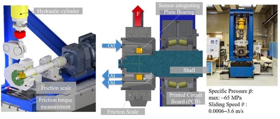
The experimental investigations conducted to verify OSF detection by TFM, which are described in Section 3.1, were performed on a test rig for hydrodynamic plain bearings with an inner diameter of di = 120 mm. The outer diameter of the test bearing is da = 180 mm and the bearing width is b = 30 mm. Figure 3 displays a schematic diagram of the 120 mm plain bearing test rig (GLP120).
Figure 3.
Test rig (GLP120).
The TFM-equipped plain bearing is located at the front of the shaft and radially loaded via a hydraulic cylinder. The hydraulic cylinder can apply a maximum radial force of FR = 250 kN, which corresponds to a specific contact pressure of approximately max ≈ 65 MPa. The SiPB-prototype is located within a friction balance, which is mounted on a pivot. Resultingly, the friction torque MR prevailing in the SiPB is measurable using a lever arm and a connected load cell. The maximum friction torque measurable in the test bearing of the GLP120 is MR,max = 550 Nm.
The electric motor, coupled to the shaft, enables sliding speeds of the shaft of up to = 3.6 m/s. Both the specific pressure and the sliding speed can be dynamically controlled. Heating elements are in the friction balance, allowing the test bearing to be heated to defined temperatures. Additionally, the lubricating oil supply into the test bearing can be heated both in the tank and in the oil supply hose. The maximum temperature to which the oil in the tank and the friction balance can be heated is TInitial,max = Toil,max = Tfb,max = 110 °C. A polyalphaolefin (PAO)-based industrial gear oil of ISO VG Class 320 (Castrol Optigear CT 320 [26]) is used as the lubricating oil. This lubricating oil is characterized by its high load-carrying capacity and is used in heavy-duty drives, such as the drivetrains of wind turbines.
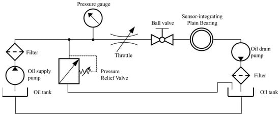
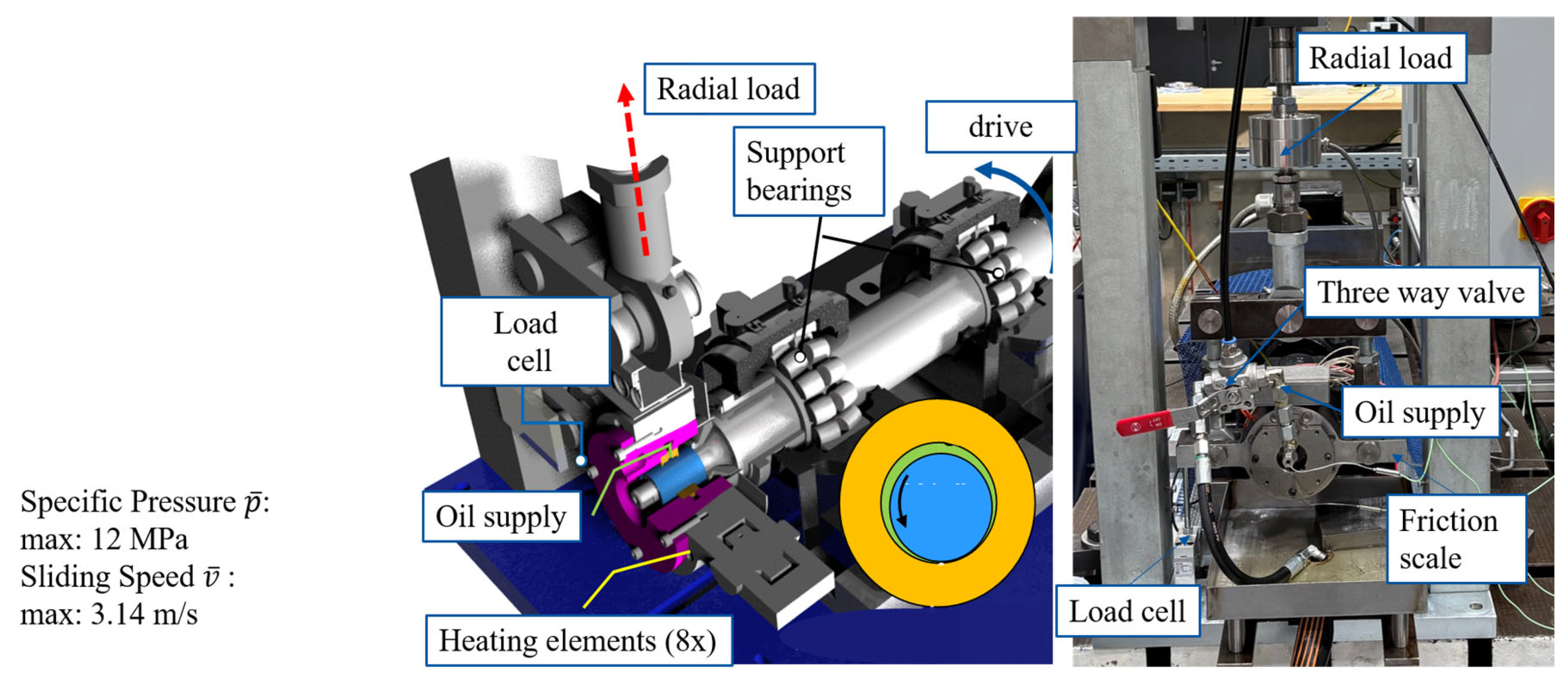
Figure 4 schematically illustrates the regular oil circuit of the GLP120 test rig. Starting from the tank, the lubricating oil is fed through a particle filter by an oil supply pump. The oil supply pressure is regulated to a constant feeding pressure into test bearing of poil,in = 0.2 MPa utilizing a pressure relief valve, pressure gauge, and throttle. From the test bearing, the oil is discharged by a return pump. Before the oil is returned to the tank, it is filtered again. A ball valve is installed in the oil supply line, which allows for complete separation of the oil supply to the test bearing during OSF testing.
Figure 4.
Schematic representation of oil circuit (GLP120).
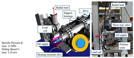
The TFM-based SiPB concept is being applied to another bearing size and experimentally validated. For this purpose, a plain bearing test rig is used to test plain bearings with an inner diameter di = 30 mm. The test bearing of the smaller size has an outer diameter da = 46 mm and a bearing width b = 15 mm. The 30 mm plain bearing test rig (GLP30) is depicted in Figure 5 below.
Figure 5.
Test rig (GLP30).
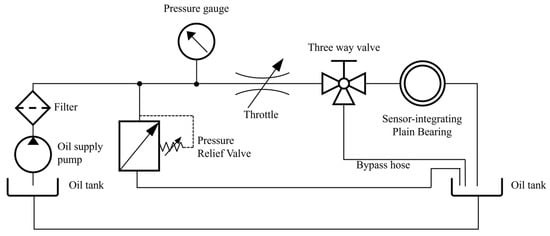
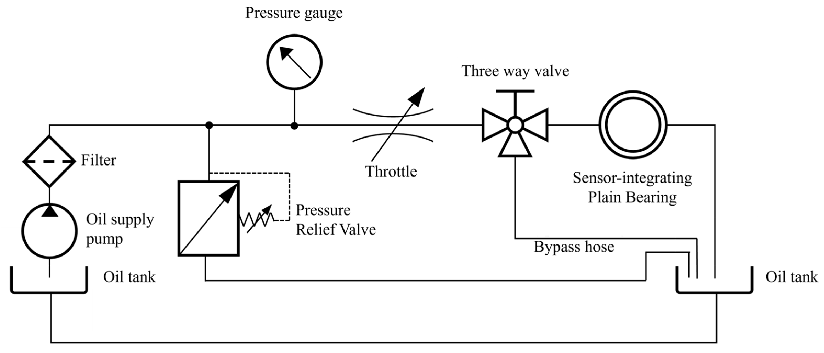
Similar to the GLP120 described above, for the smaller bearing size, the test bearing is mounted in a freely rotating friction balance, and the friction torque occurring in the test bearing is continuously measured. The radial load is applied quasi-statically using a hydraulic cylinder. A maximum force of FR,max = 5.4 kN can be achieved, which corresponds to a specific contact pressure of max = 12 MPa for the smaller bearing size tested. The maximum achievable sliding speed is max = 3.14 m/s. The direction of rotation of the shaft on the GLP30 is opposite to that of the shaft on the GLP120. The friction balance can be heated to a maximum of Tfb,max = 110 °C. The oil tank of the GLP30 is not heatable. Instead, a heatable hose is used to supply oil to the test bearing. The heating hose can heat the oil to TOil,max = 110 °C. The same lubricating oil is used as on the GLP120 test rig. Figure 6 shows a schematic diagram of the oil circuit of the GLP30 test rig.
Figure 6.
Schematic representation of oil circuit (GLP30).
As with the GLP120 test rig, the oil flows from the tank through the oil supply pump and passes through a particle filter. A defined oil supply pressure of poil,in = 0.2 MPa is set in analogy to the GLP120. A three-way valve for conducting the OSF tests is located immediately before the inlet of the oil line. During the OSF phase, the oil flow is routed past the test bearing via a bypass line. Unlike the GLP120 test rig, the GLP30 does not have a return pump. Instead, the lubricant is returned to the tank by gravity without a pump.
For both target systems, the industry-standard bronze alloy CuSn12Ni2-C [27] is used as the plain bearing material. This bearing material is characterized by a low coefficient of friction relative to steel, high wear resistance, low susceptibility to adhesion, and high adaptability to the contact partner [28,29,30]. Accordingly, the CuSn12Ni2-C alloy is a well-established plain bearing material. Both bearing sizes have a relative bearing clearance of ψ = 1.1 ‰. A shaft sleeve is used as the counterbody of the plain bearing and is replaced after each test. Using a new shaft sleeve ensures comparable surface properties for each test. The shaft sleeves are made of hardened case-hardened steel. Table 1 summarizes the relevant information regarding the test rig configurations.
Table 1.
Overview of test rig configuration.
2.4. Test Procedure
According to Marheineke, when defining emergency running conditions of plain bearings after OSF, the lubrication state is defined as a complete interruption of the oil supply [9]. The specific pressure and sliding speed are kept constant, since in industrial applications of plain bearings, the load does not change in most cases when the oil supply fails [9]. The complete interruption of the oil supply is achieved, as described in Section 2.3, via the shut-off valve (GLP120) and the three-way valve (GLP30) in the oil supply.
For the GLP120 setup, an exemplary operating point in the fluid friction region is first obtained under regular lubrication. The initial temperature of the friction balance and the oil tank is set as TInitial = 60 °C. After 30 min of regular lubrication, the oil supply is interrupted via the shut-off valve. The specific pressure and sliding speed are kept constant, and the cut-off of oil supply is maintained for another 30 min. A friction torque limit value MR,limit = 450 Nm is defined as the termination criterion. Based on the GLP120 results, TFM-based characteristics for detecting OSF are defined.
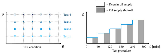
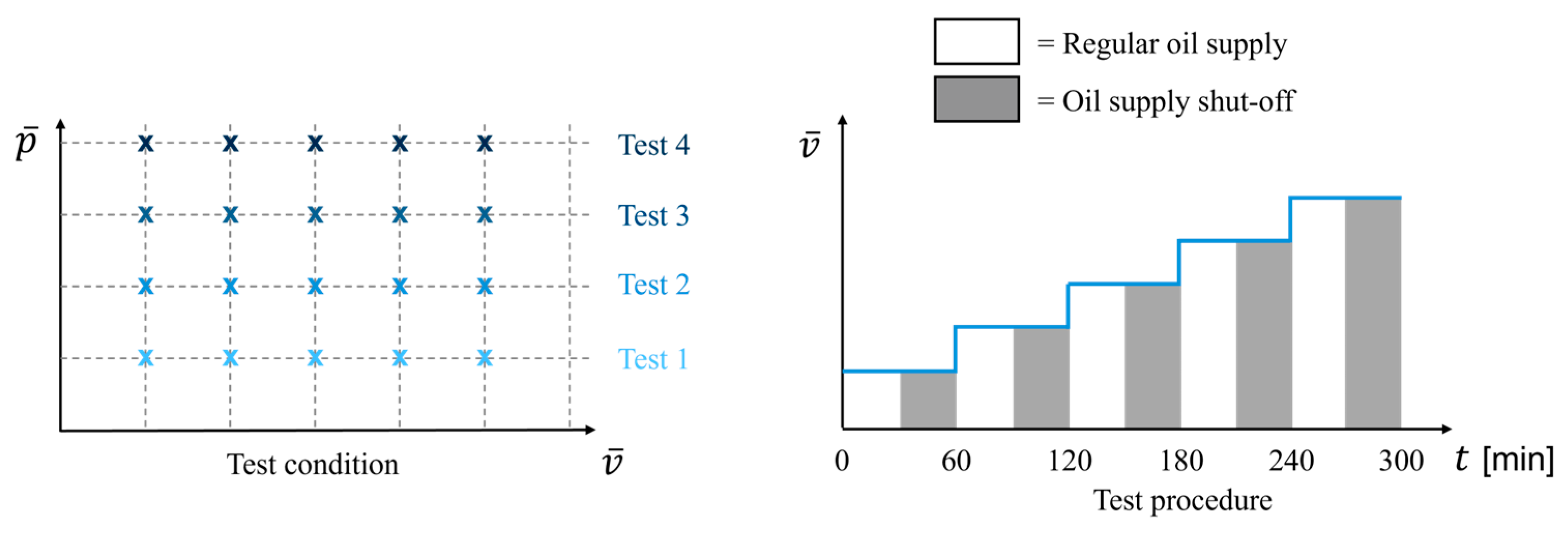
Subsequently, OSF tests are conducted on the GLP30 test rig. The goal is to validate the TFM characteristics for early OSF detection previously defined on the GLP120, thereby confirming the transferability of the developed CMS approach to other target systems. During a test conduction, a specific pressure is kept constant throughout the entire duration of the experiment. The sliding speed is increased stepwise during the experiment. A total of five speed stages ( = 1; 1.5; 2; 2.5; 3 m/s) are cycled through. During the first 30 min of each speed stage, the test bearing is supplied regularly with oil. Subsequently, the oil flow is diverted past the test bearing via the bypass line through the three-way valve. The OSF phase is maintained for another 30 min. As displayed in Figure 7, the next sliding speed stage is then initiated, and the procedure is repeated.
Figure 7.
Test procedure (GLP30).
A total of four OSF tests is conducted on the GLP30 test rig using the described procedure. The load stages investigated are specific pressures of = 4, 6, 8, and 10 MPa, which are investigated as load levels. The initial temperature of the friction balance and the lubricating oil is TInitial = 60 °C. A friction torque limit value of MR,limit = 14.5 Nm is set as the termination criterion for the tests. The termination criteria MR,limit for both target systems is set slightly below the maximum measurable friction torque value MR,max (see Section 2.3). Table 2 summarizes the test procedure parameters.
Table 2.
Overview of test procedure parameters.
3. Results—Temperature Field Measurement
3.1. Oil Supply Failure (GLP120)
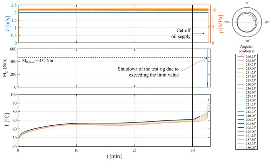
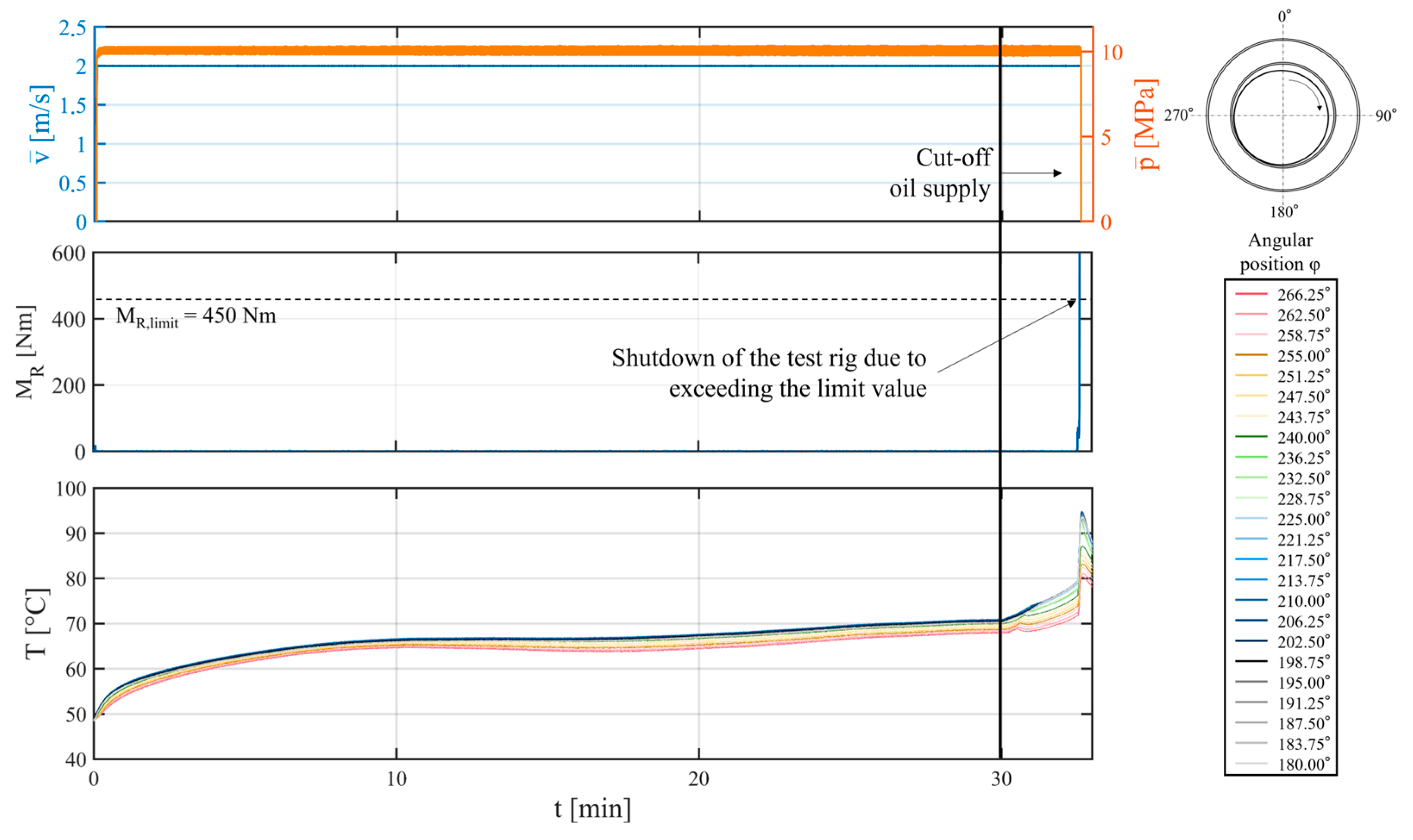
In this section, a GLP120-experiment is described in which a failure of the lubricant supply causes damage to the test bearing while measuring the temperature field. This test is intended to track the progression of damage over time, as well as changes in the temperature field and friction torque curve caused by OSF. Subsequently, based on the experimental procedure, TFM-based parameters suitable for early damage detection are discussed and defined. The initial temperature was set to TInitial = 60 °C. During the experiment, a constant sliding speed of = 2 m/s and a constant specific pressure of = 10 MPa were maintained. Under these operating conditions, fluid friction prevails with a regular oil supply. Initially, the operating conditions were maintained under a regular lubricant supply for t = 30 min to achieve a quasi-steady-state thermal condition in the bearing. After t = 30 min, the oil supply was completely shut off using the valve within the oil supply. Figure 8 displays the operating conditions (top), the measured friction torque curve (middle), and the TFM curve (bottom).
Figure 8.
Friction torque (top), temperature field (middle), and φT,max curve (bottom) of the OSF test ( = 2 m/s; = 10 MPa; TInitial = 60 °C).
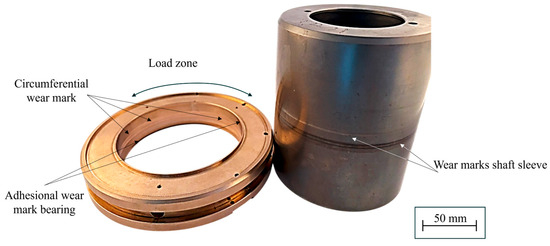
The friction torque initially remains constant immediately after the oil supply is cut off. After 2.5 min of operating time under OSF, the friction torque increases rapidly. After a total test duration of t = 32.6 min, the friction torque limit of MR,limit = 450 Nm is exceeded, ending the test. Figure 10 below will show the test segment from t = 29–33 min for better visibility. Both the plain bearing and the shaft sleeve exhibit circumferential wear marks, black discoloration, and adhesive damage with material transfer; see Figure 9.
Figure 9.
Bearing and shaft sleeve after test presented in Figure 8.
To demonstrate the detection of insufficient lubrication using TFM, Figure 10 displays the friction torque curve, the temperature field curve, and the angular position of the maximum temperature. For better visibility, only a partial time interval (t = 29–33 min) is shown.
Figure 10.
Friction torque (top), temperature field (middle), and φT,max curve (bottom) of the OSF test ( = 2 m/s; = 10 MPa; TInitial = 60 °C, t = 29–33 min).
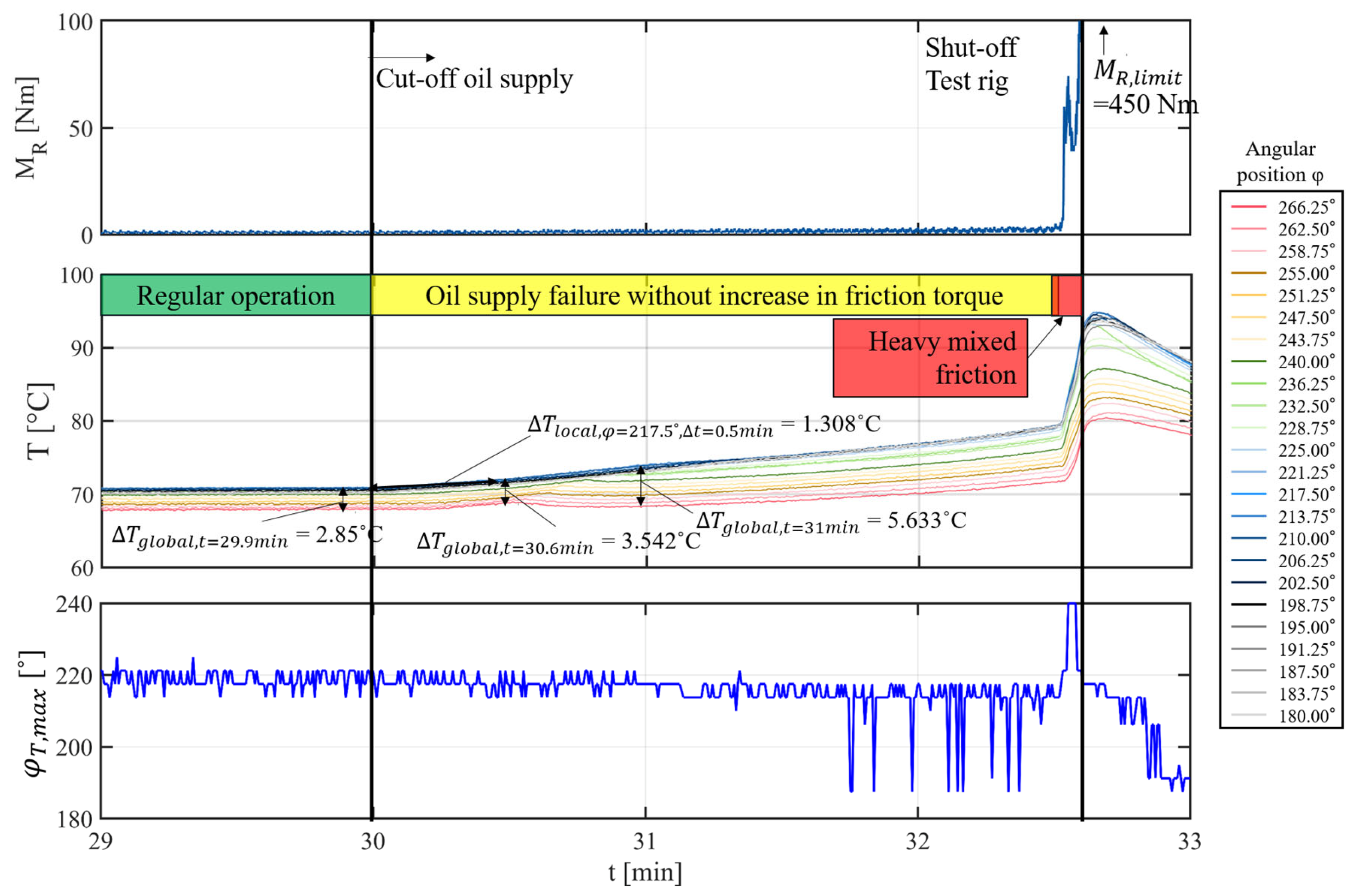
The temperature field curve illustrates that the plain bearing is in a state of thermal equilibrium before the oil supply is shut off. At time t = 29.9 min, immediately before the oil supply is shut off, the difference between the minimum and maximum temperatures is ∆Tglobal,t = 29.9 min = 2.85 °C. The angular position of the maximum temperature remains constant in the range φT,max = 213.75°–225°. The angular position φ is indicated in the direction of shaft rotation. The interruption of the oil supply is accompanied almost instantaneously by local temperature increases in the recorded temperature field. At the time the oil supply is cut off, the maximum recorded temperature occurs at the angular position φT,max = 217.5°. In the first half-minute after the oil supply is cut off, the temperature there rises by ∆Tlocal,φ = 217.5°, ∆t = 0.5 min = 1.308 °C. At the same time, a temperature increase occurs at all measurement positions in the temperature field. At time t = 30.5 min, however, a temperature drop can be observed at the higher angular positions (φ ≥ 240°). Meanwhile, the temperature continues to rise at the lower angular positions (φ < 240°), causing the global gradient to increase. One minute after the oil supply is cut off (t = 31 min), the global temperature gradient is already ∆Tglobal,t = 31 min = 5.633 °C and continues to rise over time.
Due to the increased load-bearing support resulting from the gradual reduction in the oil level of the plain bearing, more heat is introduced into the load zone, causing the temperature there to rise locally. The results suggest that changes in the lubrication condition, such as the oil fill level in the lubrication gap, can already be detected before an increase in friction torque using TFM. One possible explanation for local temperature drops resulting from insufficient lubrication in higher angular positions is that the oil film gradually runs empty. The lubricating oil gradually leaves the lubrication gap, while no additional oil is supplied to the bearing. Due to the lack of an adequate oil film, viscous shear is reduced locally, resulting in lower heat generation. Accordingly, the measured temperature initially drops at higher angular positions due to insufficient lubrication. At the same time, the remaining lubricating film in the load zone is sufficient to separate the bearing and shaft surfaces. The simultaneous temperature increases in the load zone can be interpreted as a shift in the load distribution.
The first signs of an anomaly in the reference measurement friction torque are not detectable until t = 32.53 min. The friction torque rises to a local maximum of MR = 73.96 Nm (t = 32.55 min). The friction torque then drops to a value of MR = 41.5 Nm (t = 32.57 min) and subsequently reaches the friction torque limit MR,limit = 450 Nm rapidly (t = 32.60 min), causing the test rig to shut down. Starting at the time when the friction torque increases (t > 32.53 min), sharp temperature rises occur at all measurement points due to mixed friction. At the end of the test, the maximum temperature is Tmax = 94.83 °C and the global temperature gradient is Tglobal,t = 32.57 min = 18.54 °C.
Another characteristic that can be derived from the temperature field as an alarm signal is the angular position of the maximum temperature φT,max. After t = 31.75 min, φT,max drops briefly to a value of 187.5° on several occasions. With the apparent increase in the friction torque (t = 32.53 min), the value rises to φT,max = 240°. This phenomenon can be interpreted as the shaft “climbing” along the bearing raceway in the direction of rotation due to mixed friction. Pinkus and Sternlicht also describe the displacement of the shaft in the direction of rotation due to the occurrence of mixed friction in [31].
For the test presented in this section, using the larger bearing size under consideration (GLP120), the TFM-based characteristics ∆Tglobal and φT,max were defined for the early detection of OSF. Changes in these two TFM-based characteristics occur before an increase in the friction torque of the test bearing is measured. The following Section 2.3 demonstrates that the TFM-based characteristics for early damage detection are also applicable to the smaller bearing size GLP30 and are suitable for defining alarm thresholds.
3.2. Oil Supply Failure (GLP30)
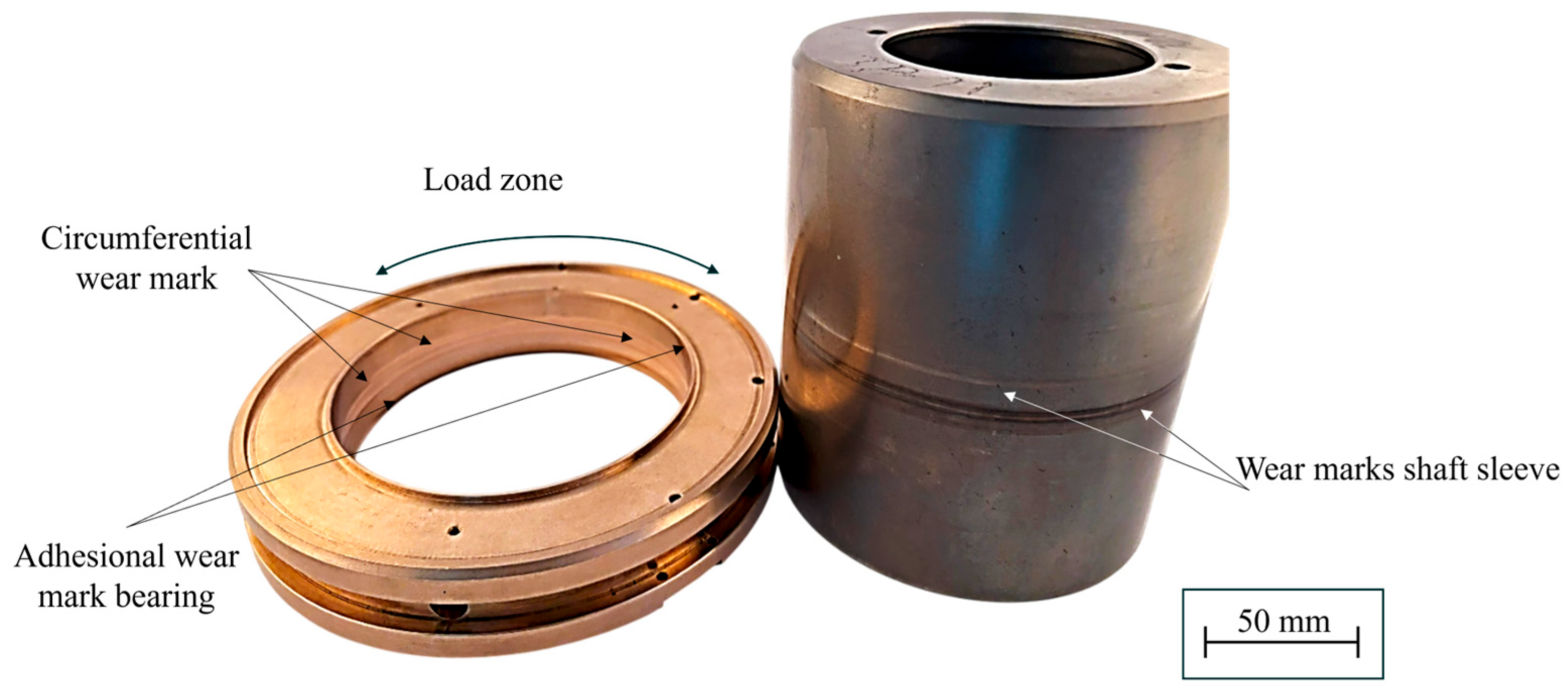
This subsection presents the experimental validation of the TFM approach and demonstrates its applicability to bearings with a diameter of di = 30 mm. Figure 11 displays the operating conditions, the friction torque curve, the temperature distribution, and the angular position φT,max for the test at a specific pressure of = 10 MPa.
Figure 11.
OSF test with GLP30 ( = 10 MPa).
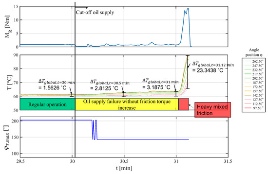
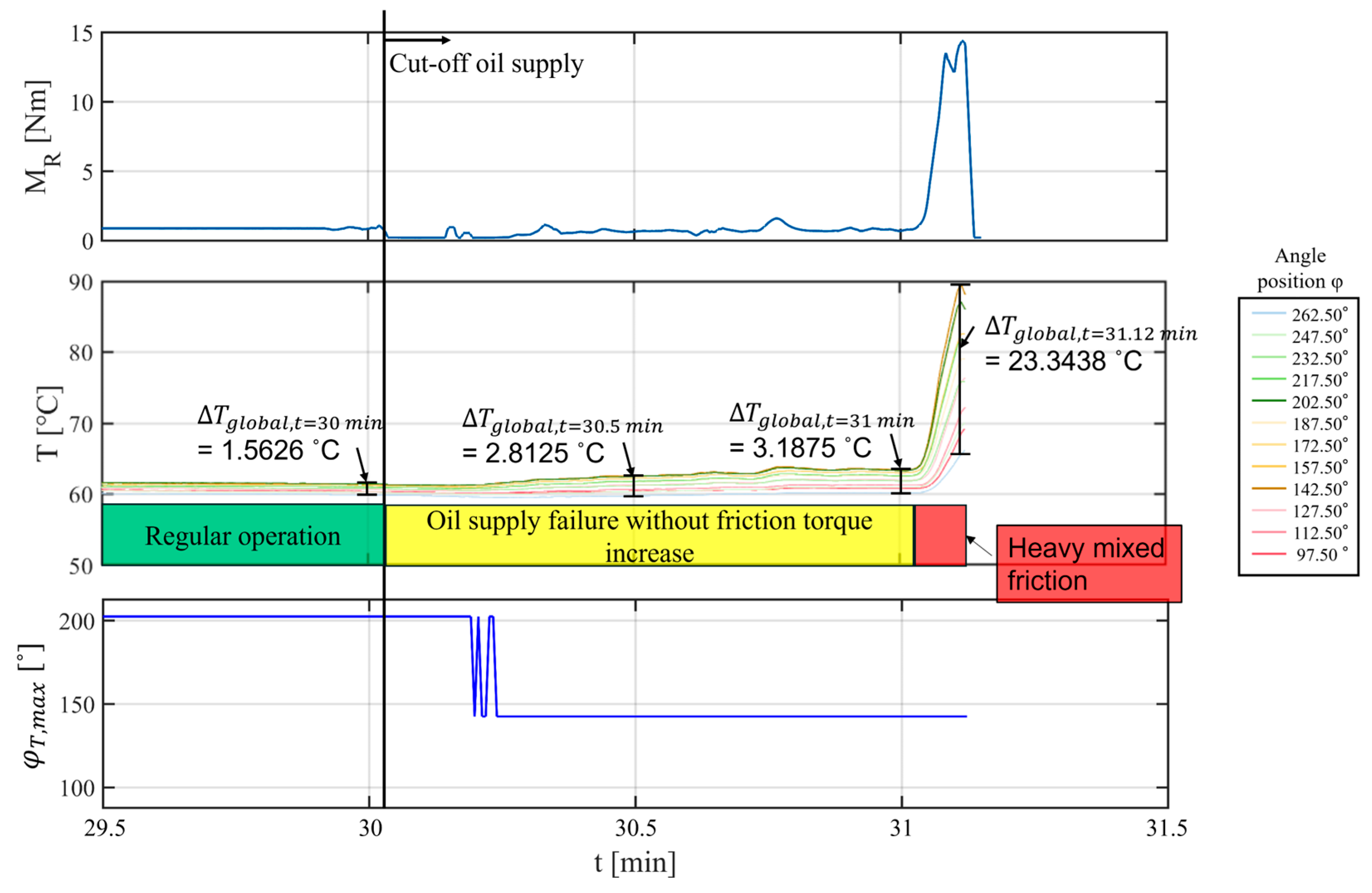
At the start of the test, the specific pressure is increased until it reaches its final value of = 10 MPa. Concurrently, the friction torque curve exhibits a local maximum (MR,t = 1 min = 2 Nm). In the subsequent phase of regular oil supply, the friction torque remains at a constant low level of MR = 0.9 Nm. The temperature field rapidly reaches thermal equilibrium. The temperature is evenly distributed. The average global temperature gradient during the phase of regular oil supply is ∆Tglobal,t = 0–30 min = 1.5323 °C. Except for brief outliers, the bearing angle of the maximum temperature remains constant at φT,max = 202.5°. At t = 30 min, the oil supply is shut off. After the oil supply is shut off, the friction torque changes discontinuously to a level comparable to that during the phase of regular oil supply. After t = 31.04 min of test duration, the friction torque rises abruptly. After t = 31.11 min, the friction torque limit is exceeded, resulting in the termination of the test. The beginning of the OSF phase is accompanied by instantaneous local temperature increases. Additionally, it can be observed that the global temperature gradient ∆Tglobal increases quickly due to the OSF. The angular position at which the maximum friction torque occurs shifts rapidly from 202.5° to 142.5°. For improved visibility, Figure 12 compares the friction torque curve with the TFM-based curves for the time interval t = 29.5–31.5 min.
Figure 12.
OSF test with GLP30 ( = 10 MPa, t = 29.5–31.5 min).
Based on the friction torque measured and the lubrication condition of the plain bearing, the test can be divided into three phases. The green phase represents the range in which there is a regular oil supply and fluid friction. The yellow phase represents the range in which an anomaly in the form of OSF is present. In the yellow phase, however, the level of the friction torque is still comparable to that in the green phase. The final test phase, in which severe mixed friction occurs due to OSF, is marked in red. Table 1 summarizes the TFM-based characteristics suitable for early damage detection for the test described above.
In the green phase, the representative time points t = 10, 20, and 30 min were examined. During the test phase with a regular oil supply, the minimum and maximum temperatures were subject to slight fluctuations of approximately ±2 °C. These fluctuations are attributable to the temperature control of the friction balance, which had been installed beforehand for the tests conducted. The control parameters for the temperature control system had not yet been optimally selected, resulting in periodic temperature oscillations in the TFM in the beginning of the experiment. However, the fluctuation in temperature occurs uniformly across all measurement positions, resulting in the global temperature gradient ∆Tglobal remaining nearly constant over time.
The transition into the yellow phase is accompanied by a rapid increase in the global temperature gradient. At t = 30.5 min, the global temperature gradient is already ∆Tglobal = 2.8125 °C. Compared to the previous time point (t = 30 min), Table 3 shows that the increase in ∆Tglobal results from a rise in the maximum temperature Tmax. At time t = 30.5 min, the minimum temperature Tmin,t = 30.5 min = 59.75 °C is lower than at the previous time point Tmin,t = 30 min = 59.9062 °C. This is consistent with the observations described in Section 3.1 regarding the temperature field of the GLP120 bearing under conditions of OSF.
Table 3.
Selected TFM-based parameters and friction torque values for the test section shown in Figure 11.
As the yellow phase progresses, the global temperature gradient ∆Tglobal increases continuously. The temperature level rises at all measurement points. In addition, a shift in the φT,max angular position is evident with the transition from the green to the yellow phase. At time t = 30.2 min, the angular position φT,max has ultimately decreased from 202.5° to 142.5° and remains there for the remainder of the test. This is followed by the transition to the red phase, characterized by mixed friction (t = 31.04 min). The prevailing mixed friction causes a high energy input into the test bearing. The temperature level rises rapidly at all measurement positions, with ∆Tglobal increasing continuously. At the end of the test (t = 31.12 min), the global temperature gradient is ∆Tglobal = 23.3438 °C.
The behavior of the temperature field under OSF exhibits similarities to the experiment described in Section 3.1 for the larger bearing size under consideration. In the green phase, under regular oil supply, the temperature distribution is uniform. The angular position φT,max and the global temperature gradient ∆Tglobal are nearly constant. In the OSF phase, in which the friction torque is at the level of normal operation (yellow), an increase in ∆Tglobal is evident. This increase in ∆Tglobal results from both an increase in the maximum temperature and a reduction in the minimum temperature. Shifts or discontinuities in φT,max is also evident. As soon as severe mixed friction occurs under OSF (red phase), the friction torque limit is exceeded within a few seconds. Concurrently, a sharp rise in temperature is observed across all measurement positions.
The following section presents the results of the additional OSF tests conducted, with particular emphasis on the characteristics ∆Tglobal and φT,max discussed above, as well as their changes following the onset of the OSF phase. The purpose is to provide reliable evidence of the suitability of these characteristics for defining alarm thresholds for early damage detection. In this context, the characteristics should already exhibit reliable changes caused by OSF during the yellow phase (OSF phase without increased friction torque). A complete presentation of the additional OSF tests is provided in Appendix A (Figure A2, Figure A4 and Figure A6).
To qualify the TFM monitoring approach, Table 4 examines the parameter ∆Tglobal immediately before the onset of OSF as well as at defined time points after the onset of OSF. The time points considered in the OSF phase are t = 5, 10, 20, and 30 s after switching off the oil supply. After 30 s in the OSF phase, no elevated friction torque levels were observed for any of the operating conditions examined compared to the preceding normal operation. Table 4 presents the ∆Tglobal values depending on the operating point (, ) for the defined time points before and after the onset of OSF. Operating points that cause the test to be terminated due to exceeding the friction torque are highlighted in gray in Table 4.
Table 4.
Measured global temperature increase after OSF for different operating conditions.
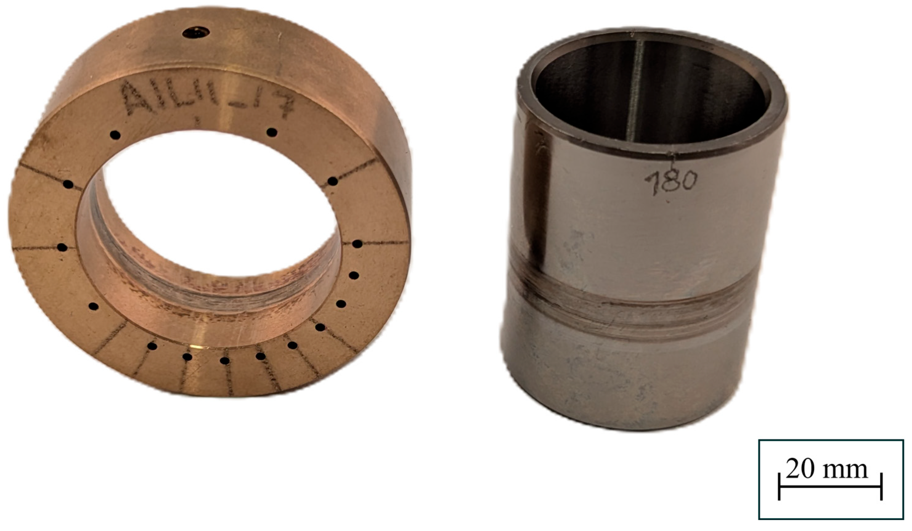
The further GLP30 tests conducted were terminated at all load levels examined ( = 4, 6, 8 MPa) at the sliding speed level = 2.5 m/s due to the friction torque exceeding the limit value. The OSF test described above ( = 10 MPa) was terminated as early as the speed level = 1 m/s. The duration between the onset of OSF and the termination of the test due to exceeding MR,limit ranged from t = 1.1467 min (68.8 s; = 1 m/s; = 10 MPa) and t = 27.502 min (1650.2 s; = 2.5 m/s; = 6 MPa) for the GLP30 tests conducted. Appendix A (Figure A1, Figure A3, Figure A5 and Figure A7) contains images of the bearings and shaft sleeves after the test was conducted. Adhesive wear marks caused by the OSF are visible on all test specimens.
For most operating points investigated, an increase in ∆Tglobal is already evident 5 s after the onset of OSF. The higher the sliding speed is, the faster an increase in ∆Tglobal develops after the OSF. After a 30 s period of OSF, an increase in ∆Tglobal was observed for all operating points examined. In the experiments conducted, there was still no increase in friction torque after 30 s compared to operation under normal lubrication conditions. The only exception is the operating point with a specific pressure = 4 MPa and a sliding speed = 1 m/s. Here, ∆Tglobal decreases moderately from ∆Tglobal = 1.09375 °C to ∆Tglobal = 0.9375 °C within the first five seconds of the OSF phase. The percentage increase in ∆Tglobal at the operating points where the test was terminated due to limit value exceedance ranged from 13.4% ( = 2.5 m/s; = 8 MPa) and 141.97% ( = 2.5 m/s; = 4 MPa) after 30 s of OSF.
In this subsection, it was thus demonstrated that the developed TFM approach can also be applied to a smaller component size. For the abnormal event of OSF, it was shown that the TFM approach is exceptionally well suited for early damage detection. The global temperature gradient ∆Tglobal, the difference between the minimum and maximum temperatures in the temperature field, was defined as the criterion for early detection of insufficient lubrication for the GLP120 configuration and confirmed for the GLP30 configuration. Except for a single operating point, it was shown that a significant increase in ∆Tglobal occurred after 30 s despite a constant friction torque level. The earliest failure following the onset of insufficient lubrication occurred after 68.8 s, providing sufficient time to implement measures to prevent damage.
4. Discussion
A sufficient oil supply is essential for hydrodynamic pressure buildup and thus for the proper operation of the plain bearing. Due to a failure of the lubricating oil supply, the plain bearing and ultimately the entire drivetrain can be damaged irreversibly within a matter of seconds. Timely detection of OSF is therefore essential, yet, as outlined in the introduction, existing condition monitoring systems either fail to detect OSF quickly enough or require costly and complex installation. To address this gap, a temperature field-based CMS approach was developed and experimentally validated by forcing OSF in test bearings of two different sizes to define TFM-based alarm characteristics for the early detection of OSF.
Initially, investigations were conducted on plain bearings of size di = 120 mm, during which the temperature field was measured. The global temperature gradient ∆Tglobal was identified as a suitable TFM-based characteristic for detecting OSF. ∆Tglobal, the temperature difference between the maximum and minimum temperatures in the temperature field at time t, increases significantly over time once the oil supply is interrupted. The increase in ∆Tglobal occurs before an increase in the plain bearing’s friction torque is detected by measurement. Hence, ∆Tglobal increased by 24.3% after 0.5 min of OSF and by 97.6% after 1 min of OSF. In contrast, the first increases in friction torque are not detectable until 2.5 min into the OSF phase.
Subsequently, the investigations were repeated on sliding bearings of size di = 30 mm. For the smaller size, ∆Tglobal was confirmed as a TFM-based parameter for detecting OSF. ∆Tglobal significantly increases after 5 s of OSF for most operating points. ∆Tglobal is significantly elevated after 30 s in all 14 operating points investigated. ∆Tglobal increased 13.4–141.97% after 30 s of supply failure over all cases investigated. The earliest plain bearing failure occurred after t = 68.8 s due to the friction torque limit being exceeded. After 30 s of lubrication supply failure, all operating points investigated do not yet show an increase in friction torque compared to the identical operating point with regular lubrication. Furthermore, the angular position of the maximum temperature φT,max can be used as an additional indicator for detecting OSF: while φT,max remains at a constant value during the normal operating phase, it fluctuates significantly (∆φT,max up to 60°) during the OSF phase. These findings demonstrate that ∆Tglobal is a robust and consistent TFM-based indicator of OSF across all 14 operating points investigated, confirming the validity of the approach, including for the smaller bearing size examined.
Thus, this study demonstrated that the developed TFM approach is exceptionally well suited for the early detection of OSF. The TFM characteristic ∆Tglobal was defined as a suitable parameter for early damage detection and validated for a second bearing size.
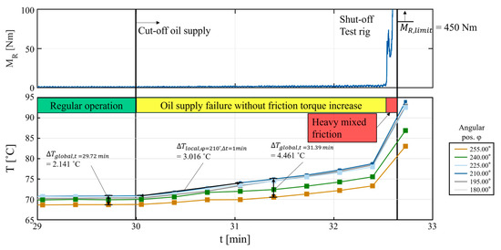
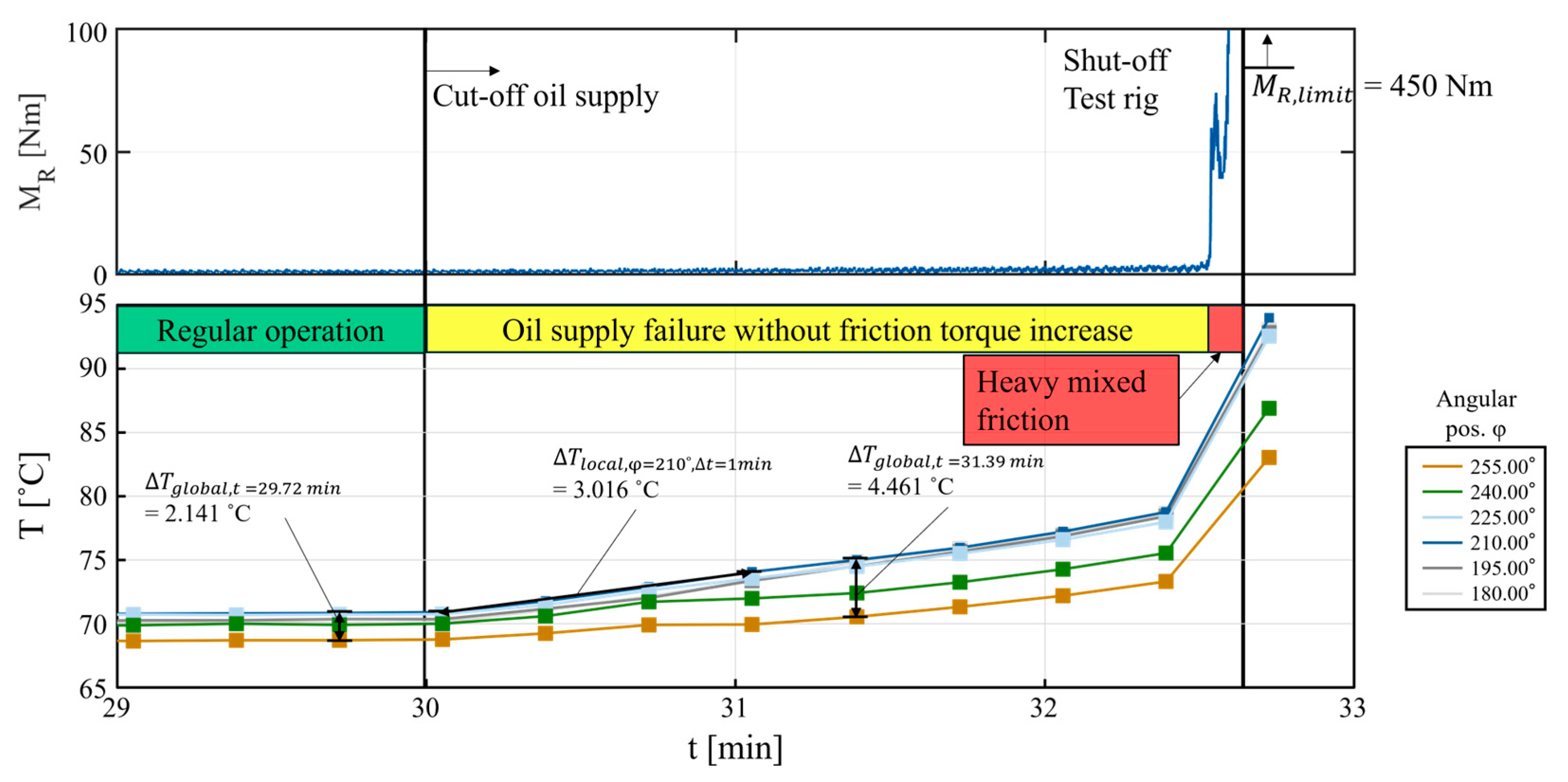
To further reduce hardware costs and energy consumption, the number of sensors and the measurement frequency of the temperature sensors can be reduced even further. As an example, the experiment described in Section 3.1—conducted with a reduced number of sensors and a lower measurement frequency—is shown in Figure 13. Six sensor positions (φ = 180; 195; 210; 225; 240; 255°) are shown at a measurement frequency of fmeas = 0.05 Hz (measurement every t = 20 s).
Figure 13.
GLP120 OSF test with a reduced number of sensors and measurement frequency.
For better visibility, the measurement points considered are each marked with a rectangle. Despite the significantly reduced measurement frequency and number of sensors, the formation of ∆Tglobal remains discernible. The influence of the number of sensors and the measurement frequency on energy consumption was outlined in [20].
To further increase the robustness of the CMS approach, the integration of a vibration sensor to estimate the shaft speed is planned. With additional knowledge of the sliding speed, a temperature rise caused by startup procedures, for example, can be reliably distinguished from temperature increases due to OSF. Inexpensive (≈US $2), energy-efficient digital vibration sensors (120 µA) with a relatively low sampling rate (6.4 kHz) are sufficient for estimating the sliding speed of the shaft [32]. In [33], it has already been demonstrated that the estimation of sliding speed is possible at the GLP120 test rig using an analog vibration sensor. The data analysis for determining the rotational speed can still be performed on the microcontroller integrated into the plain bearing. The implementation of a vibration sensor will further enhance the robustness of the fully integrated CMS approach that has been developed.
5. Conclusions
This study presented a temperature field-based condition monitoring (TFM-based CMS) approach for the early detection of oil supply failure (OSF) in hydrodynamic plain bearings. The TFM characteristic ∆Tglobal was identified as a suitable and robust indicator of OSF and was experimentally validated on two plain bearing sizes:
- •
- For the larger bearing (di = 120 mm), ∆Tglobal increased by 45.9% after 0.5 min and by 97.6% after 1 min of OSF, while a rise in friction torque was not detectable until 2.5 min into the OSF phase.
- •
- For the smaller bearing (di = 30 mm), ∆Tglobal was significantly elevated after just 5 s of OSF for most operating points and in all 14 operating points after 30 s, increasing by 13.4–141.97% across all cases, while no increase in friction torque was yet detectable.
The angular position of the maximum temperature, φT,max, was identified as an additional, complementary indicator, fluctuating by up to 60° during OSF while remaining constant under normal operation. The early changes in ∆Tglobal and φT,max are hypothesized to result from a shift in the bearing’s load-bearing pattern prior to increased mixed friction, leading to locally elevated temperatures; this hypothesis has not yet been directly verified and will be investigated in future work.
The results presented are valid for the tested bearing setups presented. Transferability to other target systems remains to be verified in each case. Furthermore, each operating condition was tested once. Repeated testing is required to assess the statistical variation and repeatability of the reported detection times and thresholds. Future work will focus on further reducing energy and hardware requirements, e.g., through optimized sensor placement and reduced measurement frequency.
Author Contributions
Conceptualization, T.B. and K.-H.K.; methodology, T.B. and K.-H.K.; validation, T.B.; data curation, T.B.; writing—original draft preparation, T.B.; writing—review and editing, G.J., T.G., B.L. and M.L.; visualization, T.B.; supervision, G.J. and T.G.; project administration, T.B., G.J. and T.G.; funding acquisition, T.B., G.J. and T.G. All authors have read and agreed to the published version of the manuscript.
Funding
Funded by the Deutsche Forschungsgemeinschaft (DFG, German Research Foundation)—466775494, 441853410.
Data Availability Statement
The data presented in this study are available on request from the corresponding author.
Conflicts of Interest
The authors declare no conflicts of interest.
Abbreviations
The following symbols and abbreviations are used in this manuscript:
| AE | Acoustic Emission |
| CMS | Condition Monitoring System |
| GLP30 | 30 mm hydrodynamic plain bearing test rig |
| GLP120 | 120 mm hydrodynamic plain bearing test rig |
| OSF | Oil supply failure |
| PAO | Polyalphaolefin |
| PCB | Printed circuit board |
| SiME | Sensor-integrating machine element |
| SiPB | Sensor-integrating plain bearing |
| TEHD | thermoelastohydrodynamic |
| TFM | Temperature field measurement |
Appendix A
Figure A1.
Bearing and shaft sleeve after OSF test with GLP30 ( = 10 MPa).
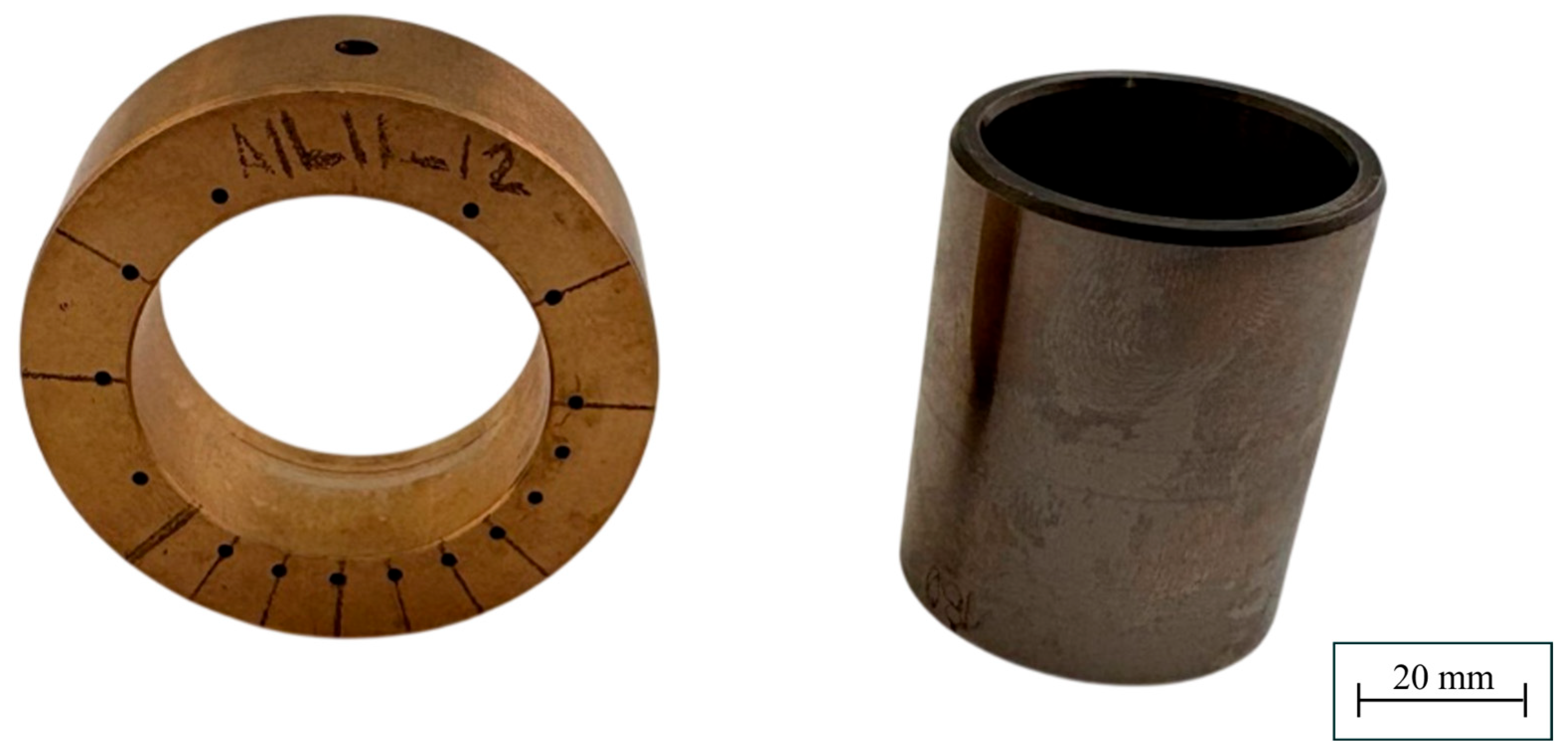
Figure A2.
OSF test with GLP30 ( = 4 MPa).
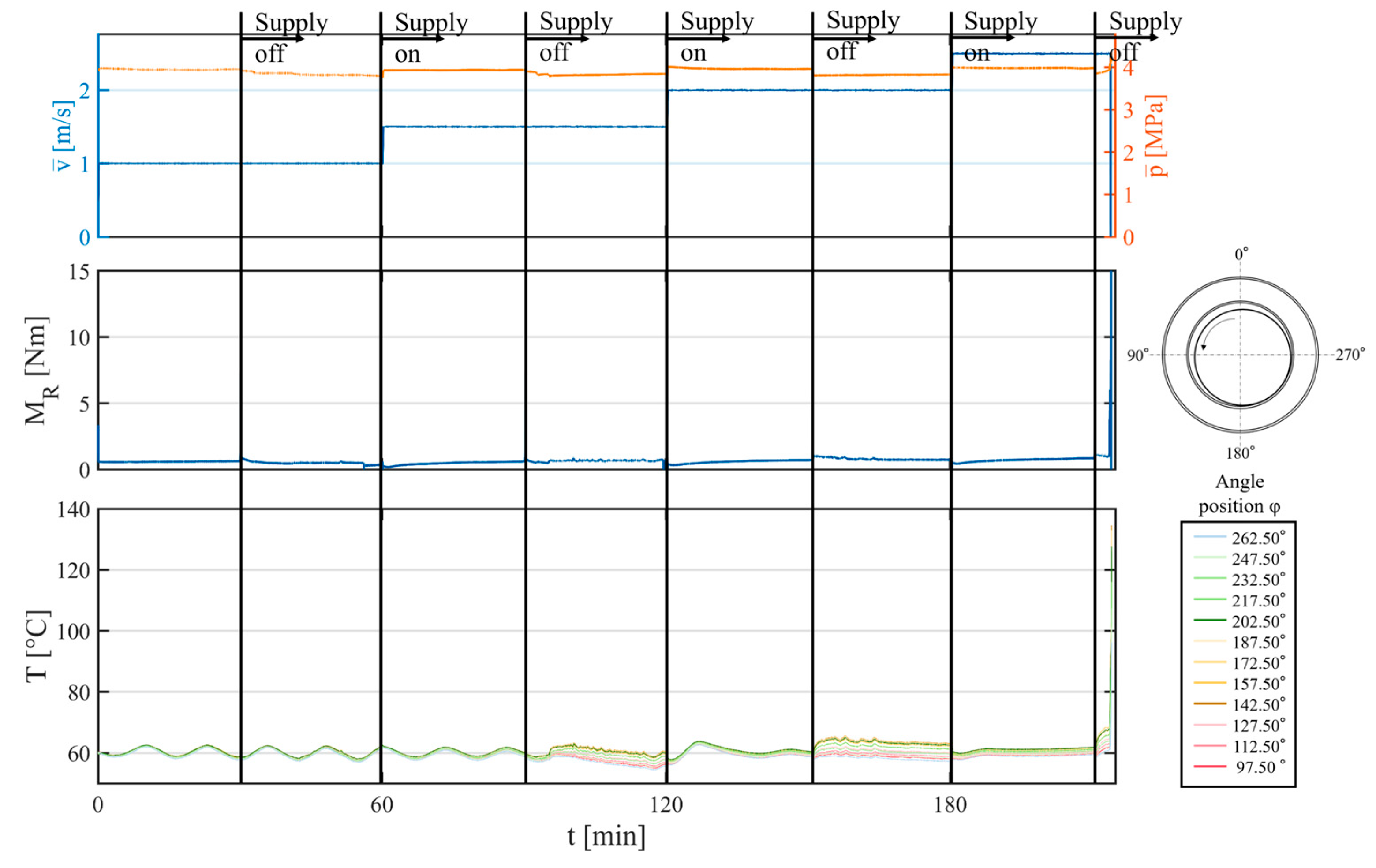
Figure A3.
Bearing and shaft sleeve after OSF test with GLP30 ( = 4 MPa).
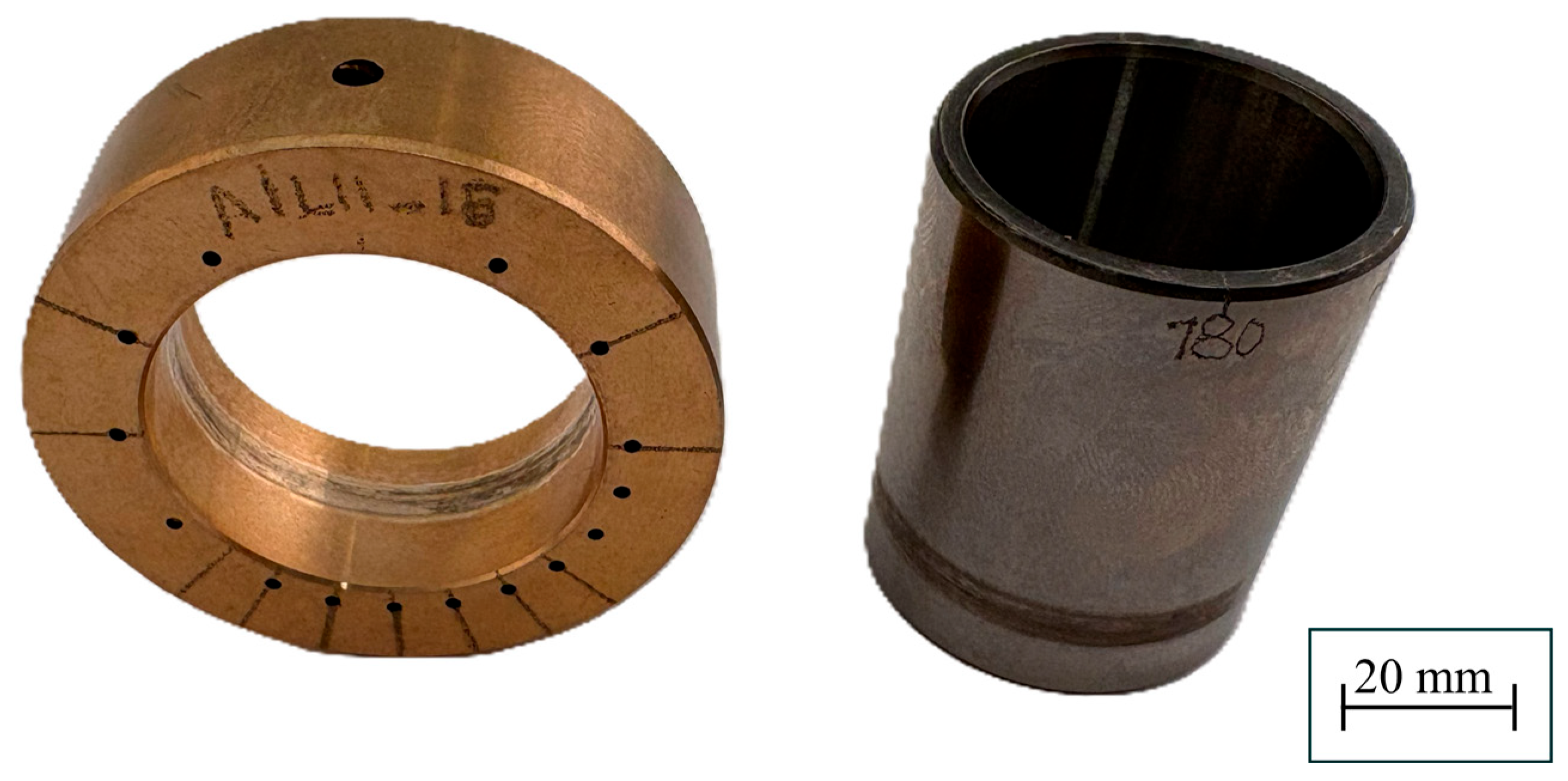
Figure A4.
OSF test with GLP30 ( = 6 MPa).
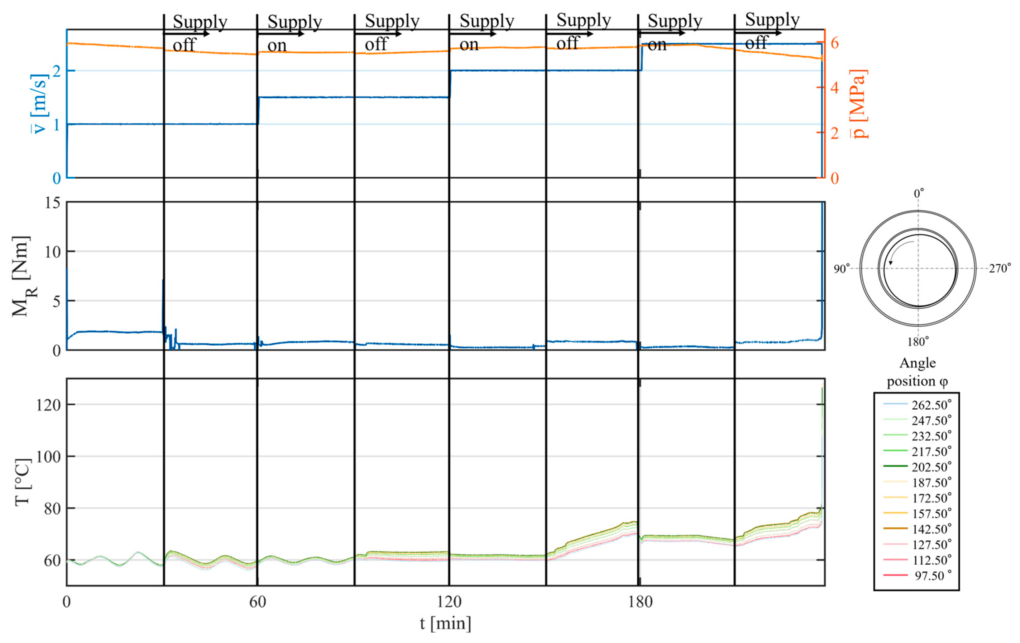
Figure A5.
Bearing and shaft sleeve after OSF test with GLP30 ( = 6 MPa).
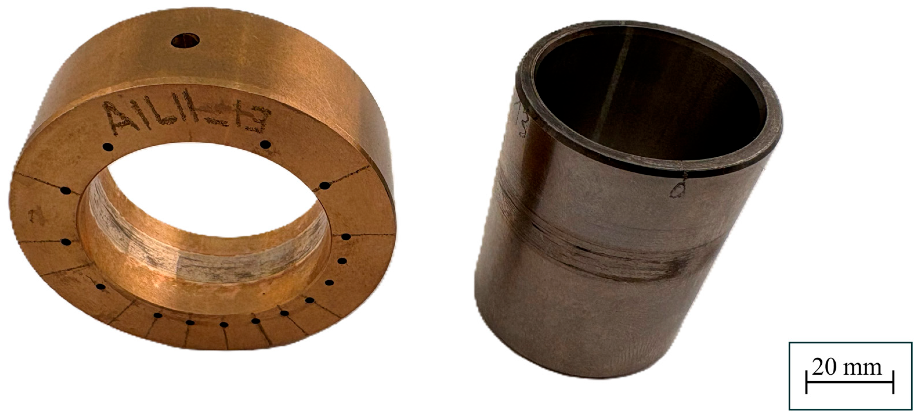
Figure A6.
OSF test with GLP30 ( = 8 MPa).
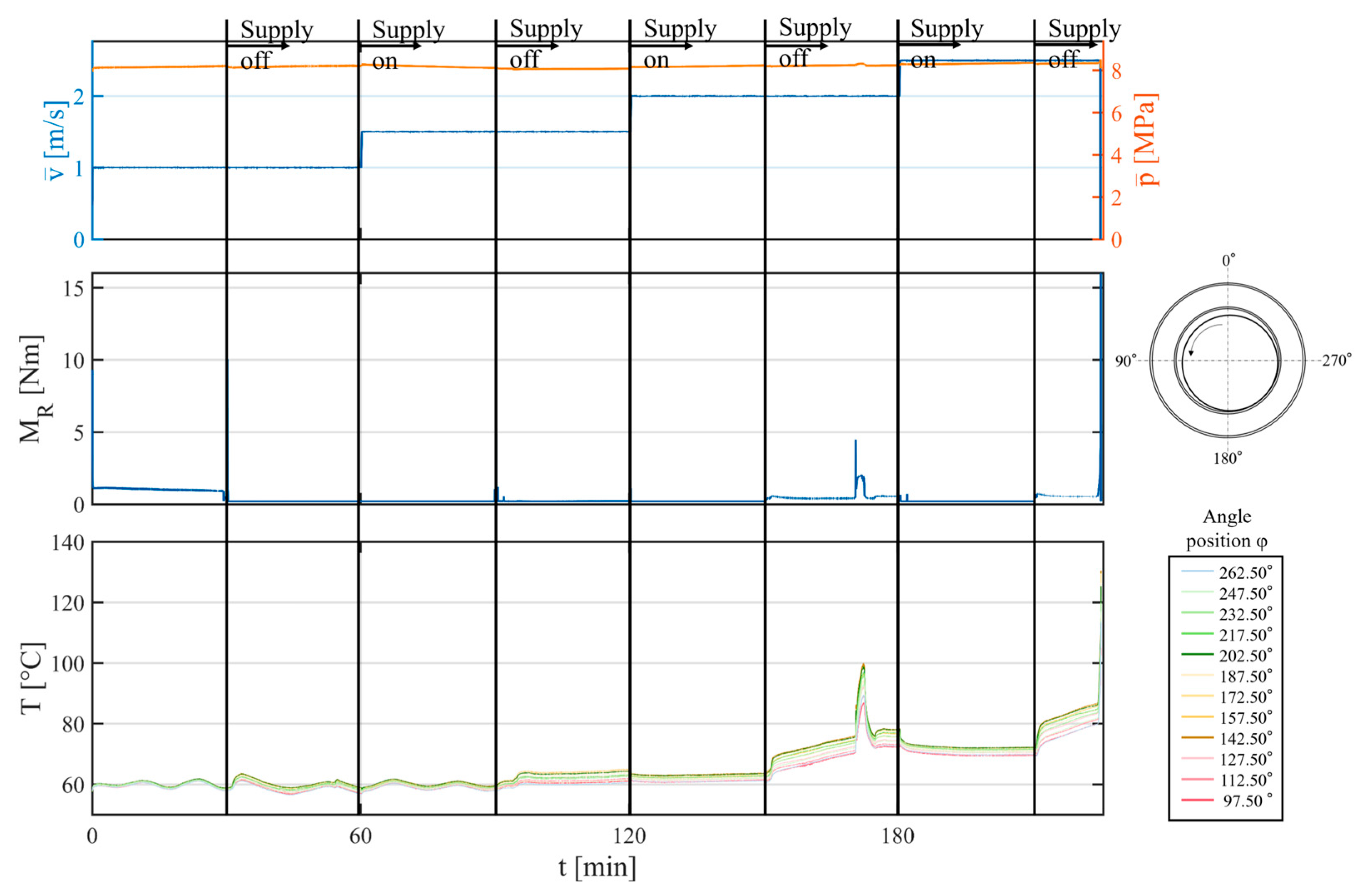
Figure A7.
Bearing and shaft sleeve after OSF test with GLP30 ( = 8 MPa).
References
- Kutay, Ş.; Kamal, B. Assessment of marine diesel engine crankshaft damages. Ships Offshore Struct. 2022, 17, 2130–2139. [Google Scholar] [CrossRef] [Scilit]
- The Swedish Club. Main Engine Damage. Available online: https://www.swedishclub.com/uploads/2024/02/TSC-main-engine-WEB2020.pdf (accessed on 7 July 2026).
- Khrulev, A. Modeling of local damage to bearings due to engine lubrication system failure. In Proceedings of the III International Scientific and Practical Conference “Modern Research in Science and Education”; Komarytskyy, M.L., Ed.; BoScience Publisher: Chicago, IL, USA, 2023. [Google Scholar]
- Zhu, S.; Yuan, W.; Cong, J.; Guo, Q.; Chi, B.; Yu, J. Analysis of regional wear failure of crankshaft pair of heavy duty engine. Eng. Fail. Anal. 2023, 154, 107635. [Google Scholar] [CrossRef] [Scilit]
- Koetz, F.; Schmitt, F.; Kirchner, E.; Zancul, E. Visualising the lubrication condition in hydrodynamic journal bearings using impedance measurement. Front. Mech. Eng. 2024, 10, 1456575. [Google Scholar] [CrossRef] [Scilit]
- Saravanakumar, A.; Raj, S.A.; Aravinthan, A.; Boolenthiran, N. Experimental analysis of plain bearing on seizure testing. Proc. Int. Conf. Mater. Manuf. Mach. 2019, 2128, 030015. [Google Scholar] [CrossRef] [Scilit]
- Wang, Q. Seizure failure of journal-bearing conformal contacts. Wear 1997, 210, 8–16. [Google Scholar] [CrossRef] [Scilit]
- DIN ISO 7146-1; Gleitlager—Erscheinungsbild und Charakterisierung von Schäden an ölgeschmierten metallischen Gleitlagern: Teil 1: Allgemeines. Deutsches Institut für Normung: Berlin, Germany; Beuth Verlag: Berlin, Germany, 2008.
- Marheineke, J. Ermittlung und Bewertung des Verhaltens von hydrodynamischen Gleitlagern bei Mangelschmierung. Master’s Dissertation, RWTH Aachen University, Aachen, Germany, 2024. [Google Scholar]
- Mokhtari Molk Abadi, N. Überwachung hydrodynamischer Gleitlager basierend auf der Körperschallanalyse. Master’s Dissertation, Technical University of Berlin, Berlin, Germany, 2020. [Google Scholar]
- Nagata, M.; Fujita, M.; Yamada, M.; Kitahara, T. Evaluation of tribological properties of bearing materials for marine diesel engines utilizing acoustic emission technique. Tribol. Int. 2012, 46, 183–189. [Google Scholar] [CrossRef] [Scilit]
- Strablegg, C.; Summer, F.; Renhart, P.; Pusterhofer, M.; Grün, F. In-depth study of direct and derived acoustic emission parameters and their information content for classifying lubricated tribological sliding contacts. Tribol. Int. 2023, 190, 109028. [Google Scholar] [CrossRef] [Scilit]
- Raharjo, P. An Investigation of Surface Vibration, Airbourne Sound and Acoustic Emission Characteristics of a Journal Bearing for Early Fault Detection and Diagnosis. Master’s Dissertation, University of Huddersfield, Huddersfield, UK, 2013. [Google Scholar]
- Hase, A.; Mishina, H.; Wada, M. Fundamental study on early detection of seizure in journal bearing by using acoustic emission technique. Wear 2016, 346–347, 132–139. [Google Scholar] [CrossRef] [Scilit]
- Collacott, R.A. Sonic monitoring of plain bearings subject to seizure. Tribol. Int. 1975, 8, 123–126. [Google Scholar] [CrossRef] [Scilit]
- Poddar, S.; Tandon, N. Detection of particle contamination in journal bearing using acoustic emission and vibration monitoring techniques. Tribol. Int. 2019, 134, 154–164. [Google Scholar] [CrossRef] [Scilit]
- König, F.; Wirsing, F.; Klinghart, B. Acoustic Emission-Based Detection of Starved Conditions to Prevent Adhesive Wear Damage in Journal Bearings. In Proceedings of the ITS-IFToMM 2024; Springer Nature: Cham, Switzerland, 2024; Volume 160, pp. 235–243. [Google Scholar] [CrossRef] [Scilit]
- Kirchner, E.; Wallmersperger, T.; Gwosch, T.; Menning, J.D.M.; Peters, J.; Breimann, R.; Kraus, B.; Welzbacher, P.; Küchenhof, J.; Krause, D.; et al. A Review on Sensor-Integrating Machine Elements. Adv. Sens. Res. 2024, 3, 2300113. [Google Scholar] [CrossRef] [Scilit]
- Baszenski, T.; Kauth, K.; Kratz, K.-H.; Gutiérrez Guzmán, F.; Jacobs, G.; Gemmeke, T. Sensor integrating plain bearings: Design of an energy-autonomous, temperature-based condition monitoring system. Forsch. Ingenieurwesen 2023, 87, 441–452. [Google Scholar] [CrossRef] [Scilit]
- Paeßens, J.; Kratz, K.-H.; Gemmeke, T.; Kauth, K.; Baszenski, T.; Lehmann, B.; Jacobs, G. Design of a fully integrated sensor system of a plain bearing. Forsch. Ingenieurwesen 2024, 88, 17. [Google Scholar] [CrossRef] [Scilit]
- DIN 31652-3; Gleitlager—Hydrodynamische Radial-Gleitlager im stationären Betrieb: Teil 3: Betriebsrichtwerte für die Berechnung von Kreiszylinderlagern. Deutsches Institut für Normung: Berlin, Germany; Beuth Verlag: Berlin, Germany, 2017.
- Baszenski, T.; Groß, J.; Kratz, K.-H.; Paeßens, J.; Jacobs, G.; Gemmeke, T.; Lehmann, B.; Lucassen, M. Experimental and simulative investigation of an energy-autarkic, temperature field-based Sensor-integrating Plain Bearing focusing transient operating conditions. Forsch. Ingenieurwesen 2025, 89, 140. [Google Scholar] [CrossRef] [Scilit]
- DIN 31692-2; Gleitlager—Teil 2: Temperaturüberwachung. Deutsches Institut für Normung: Berlin, Germany; Beuth Verlag: Berlin, Germany, 1996.
- Texas Instruments. TMP117 High-Accuracy, Low-Power, Digital Temperature Sensor with SMBus™- and I2C-Compatible Interface datasheet (Rev. D). Available online: https://www.ti.com/lit/ds/symlink/tmp117.pdf?ts=1740392415609&ref_url=https%253A%252F%252Fwww.ti.com%252Fproduct%252Fde-de%252FTMP117 (accessed on 15 July 2026).
- DIN EN IEC 60751; Industrielle Platin-Widerstandsthermometer und Platin-Temperatursensoren. Deutsches Institut für Normung: Berlin, Germany; Beuth Verlag: Berlin, Germany, 2023.
- Castrol. Data Sheet: Castrol Optigear Synthetic CT 320. Available online: https://msdspds.castrol.com/bpglis/FusionPDS.nsf/Files/DEA5BA71A44DA288802581E9003D5BEA/$File/BPXE-AU2JDS.pdf (accessed on 15 July 2026).
- Deutsches Kupferinstitut. Datenblatt: CuSn12Ni2-C. Available online: https://kupfer.de/fileadmin/user_upload/kupferinstitut.de/de/Documents/Shop/Verlag/Downloads/Werkstoffe/Datenblaetter/Bronze/CuSn12Ni2-C.pdf (accessed on 15 July 2026).
- Fontanari, V.; Benedetti, M.; Straffelini, G.; Girardi, C.; Giordanino, L. Tribological behavior of the bronze–steel pair for worm gearing. Wear 2013, 302, 1520–1527. [Google Scholar] [CrossRef] [Scilit]
- Huttunen-Saarivirta, E.; Kilpi, L.; Pasanen, A.T.; Salminen, T.; Ronkainen, H. Tribocorrosion behaviour of tin bronze CuSn12 under a sliding motion in NaCl containing environment: Contact to inert vs. reactive counterbody. Tribol. Int. 2020, 151, 106389. [Google Scholar] [CrossRef] [Scilit]
- Kowalski, M.; Górny, K.; Bernat, S.; Stachowiak, A.; Wernik, J.; Zwierzycki, W. Tribological Performance of Bronze Engineering Materials with Environmentally Friendly Lubricants Under Starved Lubrication Conditions. Materials 2025, 18, 3283. [Google Scholar] [CrossRef] [Scilit] [PubMed]
- Pinkus, O.; Sternlicht, B. Theory of Hydrodynamic Lubrication; McGraw-Hill Book Company Inc.: New York, NY, USA; Toronto, ON, Canada; London, UK, 1961; Available online: {https://babel.hathitrust.org/cgi/pt?id=mdp.39015023309126&seq=13 (accessed on 19 August 2026).
- Mouser Electronics, Inc. Bosch Sensortec BMA530. Available online: https://www.mouser.de/ProductDetail/Bosch-Sensortec/BMA530?qs=2wMNvWM5ZX4xN1KGqjzO%252Bg%3D%3D&srsltid=AfmBOoqGzPDNoVQ7v2yhuEaC349r1nz4fjDOa9N1EXEIAYvHs2L-lv0O (accessed on 13 April 2026).
- Liebich, R.; Gühmann, C.; Jacobs, G.; Ahmadzadeh, M.; Kliemank, M.L.; Baszenski, T. DFG SPP 2305 Projektübergreifende Messkampagne zur Drehzahlabschätzung in Gleitlagern; Technical University of Berlin: Berlin, Germany, 2024. [Google Scholar] [CrossRef]

Disclaimer/Publisher’s Note: The statements, opinions and data contained in all publications are solely those of the individual author(s) and contributor(s) and not of MDPI and/or the editor(s). MDPI and/or the editor(s) disclaim responsibility for any injury to people or property resulting from any ideas, methods, instructions or products referred to in the content. |
© 2026 by the authors. Licensee MDPI, Basel, Switzerland. This article is an open access article distributed under the terms and conditions of the Creative Commons Attribution (CC BY) license.