


Abstract
Electric-shovel top sheave bearings with sensor-embedded slots operate under harsh service loads, making them prone to fatigue crack initiation and propagation. Accurate predictions of crack growth within the bearing body are therefore essential for intelligent bearing design and reliability assessments because the bearing integrity directly affects shovel service life and safety. This paper presents a sub-modeling-based method that embeds initial cracks while preserving actual roller-ring boundary conditions and ensuring computational efficiency via adaptive mesh refinement. A global model first identifies critical crack-prone zones, after which the sub-model systematically examines the effects of the initial crack angle and sensor-embedded slot depth on the propagation behavior. The results indicate that both factors significantly increased the stress intensity factor (SIF). Among the evaluated designs, the 15 mm -deep slot produced the highest SIFs and the shortest predicted crack-propagation life, indicating that slot depth was a key design parameter under the investigated conditions. The findings provide theoretical support for the structural design and fatigue evaluation of intelligent electric-shovel top sheave bearings.
1. Introduction
Rolling bearings are critical components in mechanical equipment, and their performance plays a decisive role in the service life and operational reliability of the entire system. Under high loads and harsh working environments, bearing failure is significantly accelerated [1]. Among various bearing types, tapered roller bearings, owing to their characteristic tapered raceway design, are capable of simultaneously carrying radial and axial loads, and are therefore widely used in heavy-duty engineering machinery such as excavators, cranes, and mining equipment [2]. However, conventional bearing condition monitoring methods still suffer from inherent limitations, as they cannot provide real-time information on the bearing operating status or effectively warn of potential failure. With the rapid development of intelligent monitoring technologies, embedded sensors have emerged as an important approach for real-time condition monitoring. Nevertheless, the introduction of sensor-embedded slots may alter the local stress distribution within the bearing, thereby promoting crack initiation and propagation and ultimately reducing the service life and reliability of the original structure. Therefore, investigating the crack-propagation behavior of engineering machinery bearings containing sensor-embedded slots is of considerable scientific and practical significance. From the perspective of mechanical behavior, the presence of a sensor-embedded slot modifies the local stress field, while crack propagation is also affected by material crack-growth behavior, rolling-contact fatigue damage, lubrication/contact conditions, and the initial crack configuration [3,4,5]. These effects need to be clarified through multiscale simulations so as to reveal the underlying mechanisms and provide guidance for structural design.
Numerical simulations have become an important tool for investigating the dynamic response and fatigue-crack evolution of rolling bearings. Finite-element models can resolve contact stress distributions and characterize progressive damage under cyclic loading, thereby supporting multiscale analyses of crack initiation and propagation. He et al. [6] proposed a method for predicting the rolling-contact fatigue in offshore wind-turbine pitch-bearing raceways and demonstrated that the contact stress distribution and crack-growth parameters strongly affect the raceway fatigue life. To improve the computational efficiency, some studies have replaced moving contact loads with cyclic static contact loads at a stress ratio of zero and evaluated the rolling-contact-fatigue life using stress-life methods [7]. Zhao et al. [8] measured the roller tilt angle in a double-row tapered roller bearing using strain gauges, demonstrating that direct strain measurements can characterize the internal operating state of tapered roller bearings.
At the contact-mechanics level, Chen et al. [9] investigated elastohydrodynamic lubrication in tapered roller bearings while considering the effect of roller free ends, highlighting the importance of the local contact and lubrication conditions in the bearing performance. Ren et al. [10] investigated the load-carrying performance and fatigue life of a double-supported tapered roller bearing in an offshore wind turbine, providing a recent example of the mechanical and durability assessment of large tapered roller bearing systems. Darmo et al. [11] analyzed the failure of the outer ring of a double-row tapered roller bearing used in a coal wagon wheelset, showing that tapered roller bearings are susceptible to complex damage under heavy-duty service conditions. Ren et al. [12] developed a mixed-mode stress intensity factor calculation model for the expansion behavior of rolling contact fatigue cracks (RCFs), and their numerical simulation results showed that the propagation of subsurface cracks is the key causative factor for inducing raceway spalling. More directly related to intelligent bearing design, Wang et al. [13] investigated sensor-embedded slots in heavy-duty bearing rings and demonstrated that the groove depth and axial position affect the local temperature, stress, and strain responses. FRANC3D 8.5.1 has also been coupled with finite-element packages, including ANSYS 2024 and Abaqus 2022, to efficiently predict crack geometry, propagation paths, and fatigue life [14].
However, despite recent progress in the contact, load-carrying, and fatigue analysis of large tapered and pitch bearings, fracture-mechanics studies of sensor-embedded slots in large tapered roller bearings (>400 mm) remain limited, particularly under realistic roller-to-ring constraints. Smart bearings, recognized as a key enabler of intelligent mining equipment, require embedded sensors to acquire internal signals for design and maintenance support. Yet, the necessary sensor-embedded slots inevitably alter the bearing structural integrity and stress distribution, affecting damage evolution. The influence of the sensor-embedded slot location and depth on the crack-propagation life remains unclear. To address this, the study used FEM simulations integrating fracture mechanics to investigate the crack behavior under varying sensor-embedded slot depths. The MTS criterion and Paris law were employed to predict the crack path and growth rate. A comparison with outer-ring subsurface cracks revealed the effects of the slot geometry on the crack path and crack-propagation life, providing a theoretical basis for the structural optimization and reliability design of sensor-embedded bearings in engineering machinery.
2. Theoretical Methods of Fatigue Crack Propagation
2.1. Stress Intensity Factor Based on Fracture Mechanics
Bearing contact stresses are mainly solved with Hertz contact theory [15,16]. For line contact between a roller and a raceway, the maximum contact stress is determined by the following equation:
where Q is the roller-raceway contact load, l is the effective contact length, and b is the half-width of the Hertzian contact zone, given by
where is the sum of the principal curvatures of the two contacting surfaces, E is Young’s modulus, and v is Poisson’s ratio.
In this study, fatigue crack propagation in electric-shovel top sheave bearings containing sensor-embedded slots is analyzed using fracture mechanics, which provides a theoretical framework for evaluating the crack-tip stress field. For a crack subjected to a non-uniform stress field, Wu et al. [17] expressed the Mode I stress intensity factor (SIF) in the following direct form using the generalized weight-function method:
where is the crack length, σ is the stress distribution acting on the prospective crack plane, and is the weight function determined by the crack and component geometry. Equation (3) provides a concise relationship between the stress distribution and the corresponding Mode I SIF.
Numerical crack analyses can be formulated using enriched finite-element methods [18] or energy-integral approaches [19]. Because the present bearing problem involves a three-dimensional mixed-mode crack field, the three SIF components, KI, KII, and KIII, were evaluated using the interaction-integral method implemented in FRANC3D [20]. At each crack-front point, the interaction integral between the actual FE field and an auxiliary unit-mode field is written as
where superscripts (1) and (2) denote the actual FE field and the auxiliary field, respectively. V is the local integration volume surrounding the crack front; are the stress, displacement, and strain components, respectively; x1 is the local crack-extension direction; and is the Kronecker delta. The interaction strain-energy density is defined as
For an isotropic linear-elastic material, the interaction integral is related to the mixed-mode SIFs by:
where under plane-strain conditions and = under plane-stress conditions, and is the shear modulus. By successively introducing unit Mode I, Mode II, and Mode III auxiliary fields, the three SIF components are obtained as
In the present analysis, the actual displacement, stress, and strain fields were obtained from the cracked Abaqus sub-model. The displacement derivatives were evaluated at the integration points using the FE shape-function derivatives in the local crack-front coordinate system established by FRANC3D. The corresponding unit Mode I, II, and III auxiliary fields were then generated for the interaction-integral calculation.
The virtual crack-extension function q was set to unity at the crack front and zero at the outer boundary of the integration domain, with its values and spatial derivatives interpolated using the FE shape functions. Numerical integration of the actual and auxiliary fields over the local domain surrounding the three-ring crack-front mesh yielded , and . The corresponding SIF components were obtained using Equation (7) by successively applying unit Mode I, Mode II, and Mode III auxiliary fields at each crack-front point and propagation increment.
2.2. Crack-Propagation Rate Model
The state at the crack tip is governed by three types of stress intensity factors, of which KI, KII, and KIII can be expressed by equivalent SIFs [21]:
The equivalent SIF range during one loading cycle is defined as:
where and are the maximum and minimum equivalent SIFs during the loading cycle, respectively. According to the fatigue crack growth law proposed by Paris and Erdogan [22], the crack growth rate is considered to be proportional to the SIF, i.e.,
where a is the crack size, N is the number of stress cycles, is the equivalent SIF range, and C and n are Paris-law material constants.
For the bearing steel considered, C = 3 × 10⁻¹¹ and n = 3 were selected as representative Paris-regime parameters with reference to recent crack-growth studies of bearing steels and pitch-bearing raceways [3,21]. GB/T 6398-2017 [23] was used as the fatigue crack-growth testing standard. The same constants were applied consistently to all investigated cases. Repeated roller passage was represented by a pulsating local contact-loading cycle with RL = 0, and the crack-growth increment was adaptively varied from approximately 0.045 to 0.09 mm. Crack growth was terminated at the last increment successfully remeshed in FRANC3D and converged in Abaqus; no prescribed critical crack length or fracture-toughness threshold was applied.
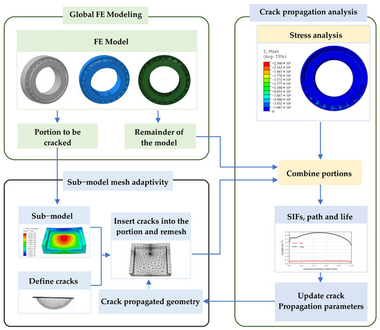
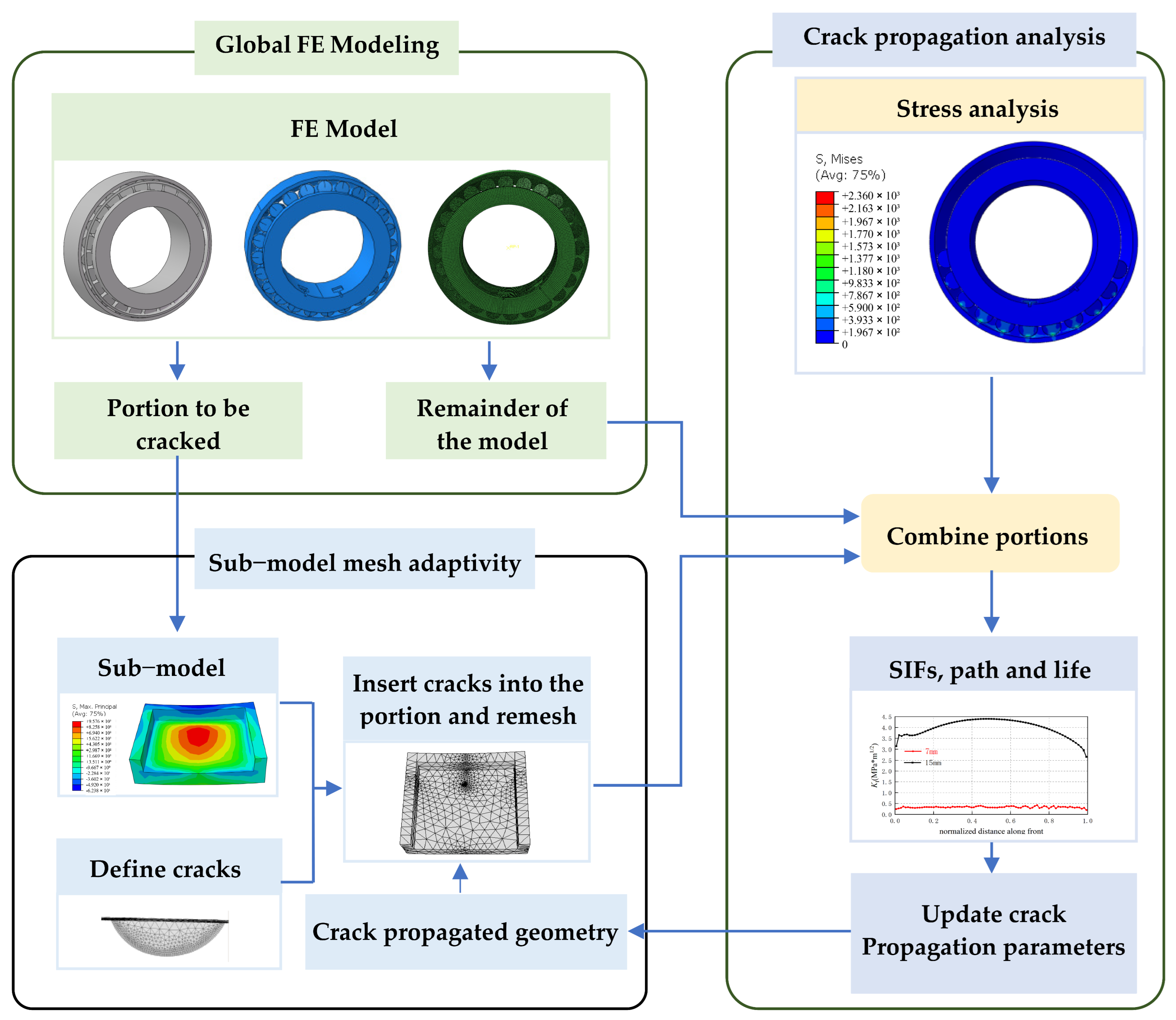
The numerical workflow is summarized in Figure 1. A local region was extracted from the global bearing model, and the global boundary displacements were transferred to its cut boundaries. Initial cracks were inserted and locally remeshed, followed by iterative Abaqus-FRANC3D analyses to determine the SIFs, crack paths, and crack-propagation lives. Crack propagation from the sensor-embedded slot surfaces was then compared with that of outer-ring subsurface cracks. The crack-growth direction at each crack-front point was determined using the maximum tangential stress (MTS) criterion in the local crack-front coordinate system. Under mixed Mode I/II loading, the local kink angle , measured from the current crack plane, was calculated as
where the solution corresponding to the maximum circumferential tensile stress was selected, and when . The local and values were obtained from the M-integral at each crack-front point, while was included in the equivalent SIF used to determine the crack-growth rate. The predicted growth directions were applied pointwise along the three-dimensional crack front. The updated crack front was then smoothed, locally extended, remeshed, and re-solved for the next growth increment.
Figure 1.
Flowchart of crack-propagation research.
3. Global Finite Element Modeling and Validation
3.1. Structural Feature of the Top Sheave Bearing in Electric Shovels
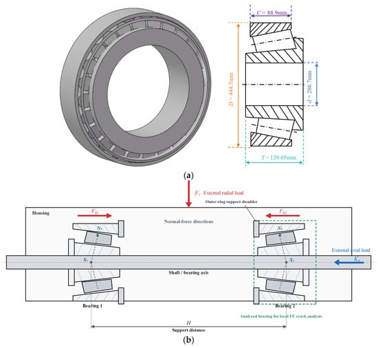
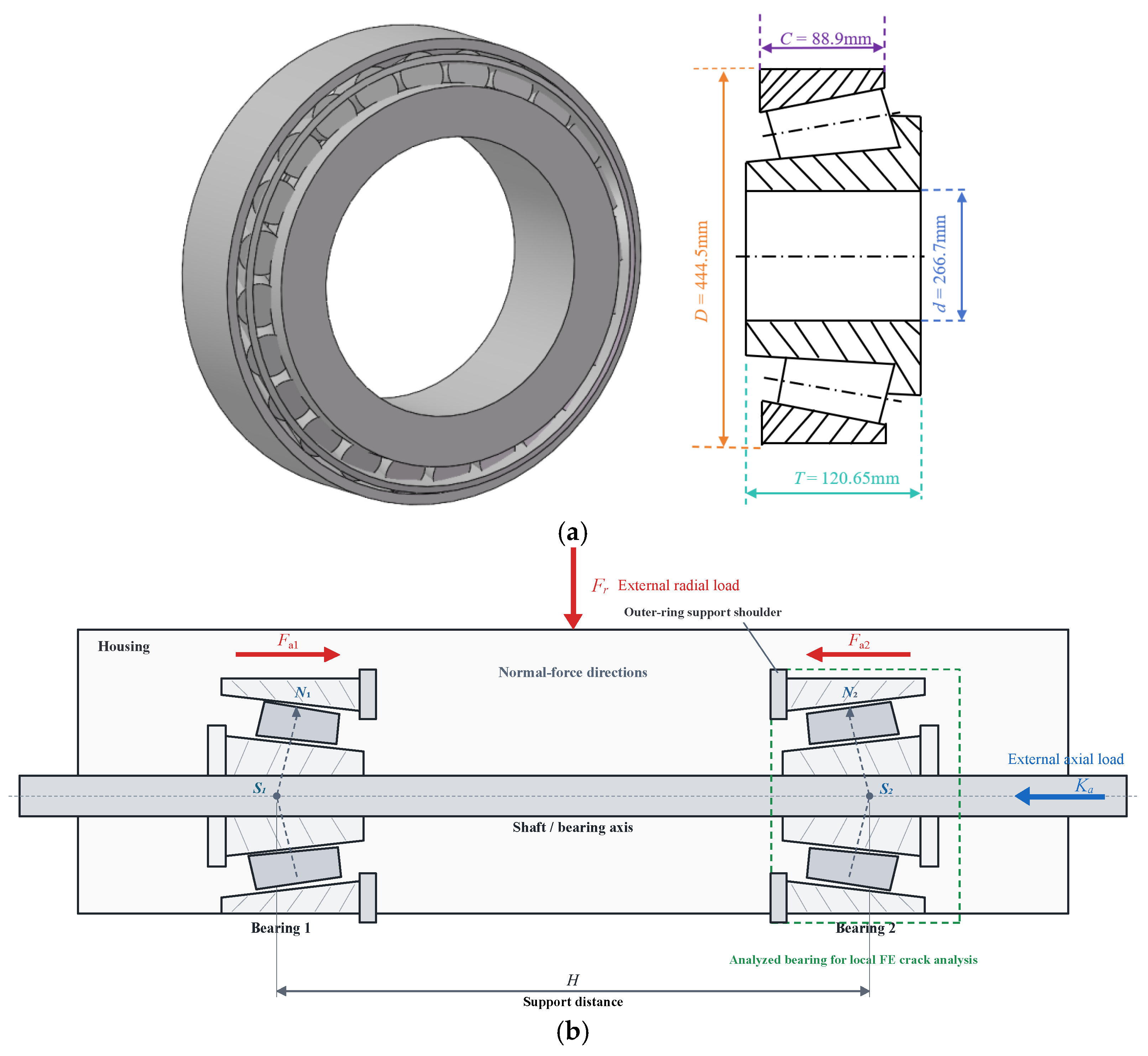
The H852849/H852810 single-row tapered roller bearings used in the electric-shovel top sheave comprised an outer ring, an inner ring, an integral cage, and 24 tapered rollers. Their principal dimensions are listed in Table 1 and illustrated in Figure 2a; the inner-ring bore diameter, d = 266.7 mm, corresponded to the nominal shaft-journal diameter. The material had a density of 7850 kg/m3, a Young’s modulus of 208 GPa, and a Poisson’s ratio of 0.3.
Table 1.
Geometric and catalog parameters of the bearing.
Figure 2.
Bearing structure and support arrangement: (a) three-dimensional model and structural schematic; (b) shaft-bearing support system in an O arrangement.
3.2. Sensor-Embedded Slot Structure for Smart Bearing Application
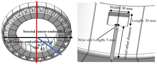
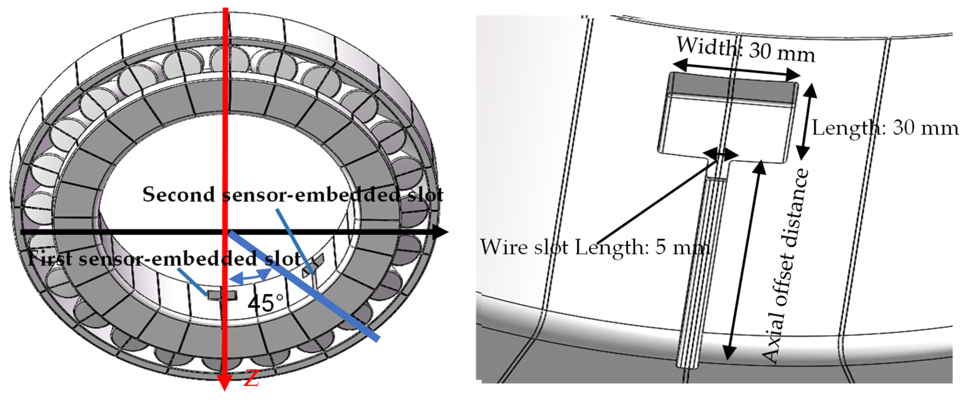
Two rectangular sensor-embedded slots with lead holes were machined in the inner ring of the electric-shovel top sheave bearing. The slots were oriented 45° apart, and each measured 30 mm in length, 30 mm in width, and either 6 or 15 mm in depth, with an internal fillet radius of 1 mm. Both slots were located 30 mm from the large end face of the bearing. Their geometric configuration and dimensions are shown in Figure 3.
Figure 3.
Schematic diagram of the sensor-embedded slot structure of the smart bearing.
The selected depths of 6 mm and 15 mm represent the lower and upper bounds of the project-defined installation range, respectively, as determined by the sensor-package dimensions and the available embedding space. They were therefore adopted as representative engineering cases to evaluate the sensitivity of the bearing integrity to the slot depth, rather than as universal design values.
3.3. Mesh Convergence Test
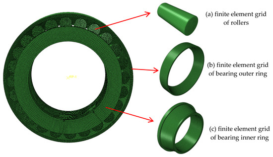
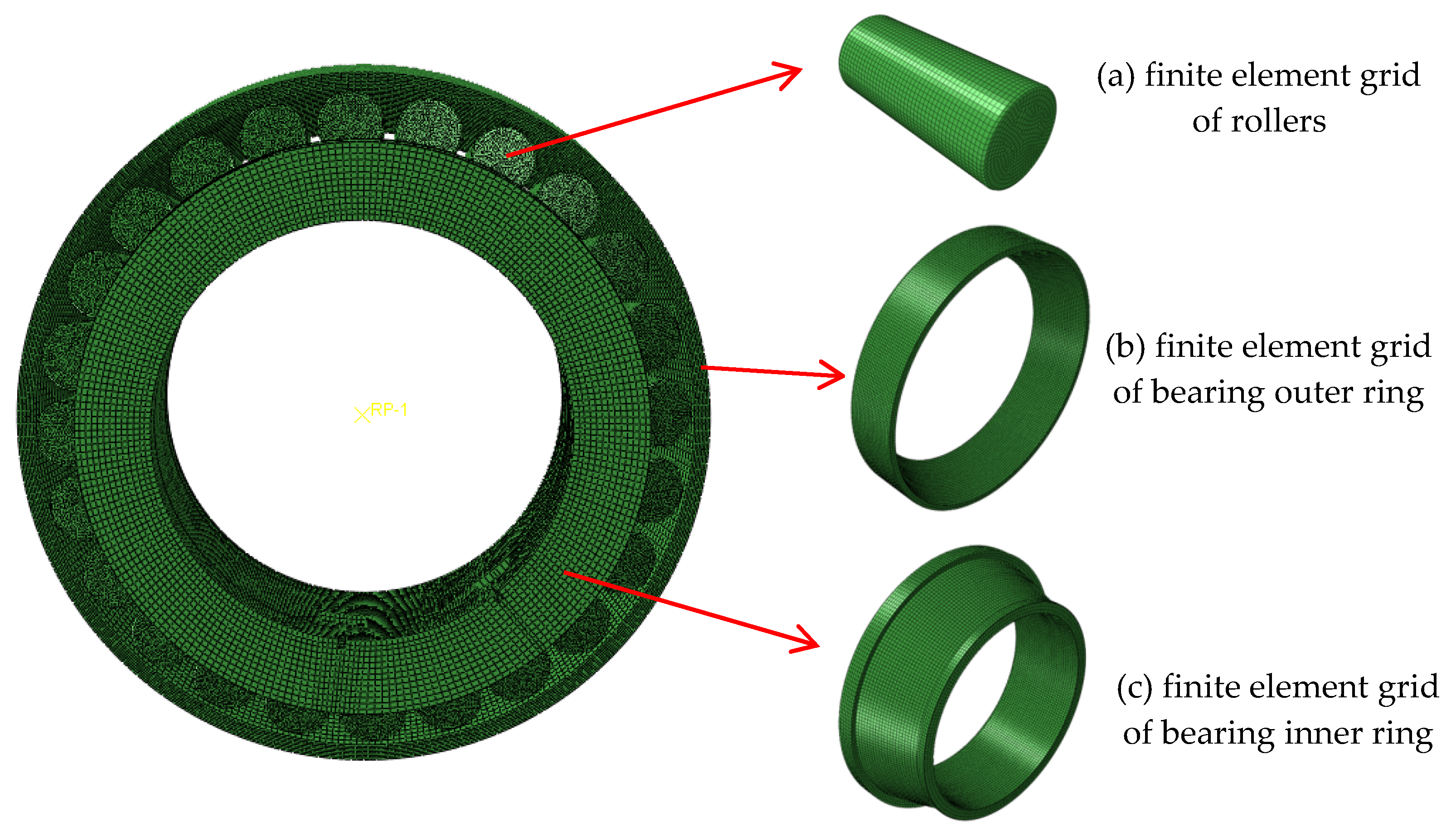
The global bearing model was developed and solved using Abaqus 2022, while crack insertion, adaptive remeshing, and the crack-growth analysis were performed using FRANC3D 8.5.1. The global model was discretized using C3D8R hexahedral elements (Figure 4), and a mesh convergence test was conducted before the stress analysis. Five mesh sizes of 5.5, 5.0, 4.5, 4.0, and 3.5 mm were examined, with the maximum von Mises stresses of the outer and inner rings adopted as convergence indicators.
Figure 4.
Global finite element model of the bearing with sensor-embedded slots.
As shown in Table 2, the maximum stresses varied within a narrow range among the tested meshes. Compared with the 3.5 mm mesh, the 4.5 mm mesh produced differences of only 0.97% for the outer ring and 0.35% for the inner ring. Therefore, the 4.5 mm mesh was selected to balance the numerical accuracy and computational efficiency.
Table 2.
Mesh-convergence test.
The global and local meshes served different purposes. The global C3D8R mesh was used to obtain the overall stress field and boundary displacements for the sub-model. The crack-containing region was subsequently extracted and imported into FRANC3D, where it was locally remeshed with elements refined toward the crack front. The remeshed region was then recombined with the remaining model and solved in Abaqus. Thus, the M-integral was evaluated over the integration domain surrounding the crack front in the locally refined sub-model, rather than using the global mesh shown in Figure 4. The final global model contained 1,996,458 nodal degrees of freedom, while the representative initial-crack model contained 2,127,708 nodal degrees of freedom.
3.4. Bearing Stress Analysis Based on Global Finite Element Model
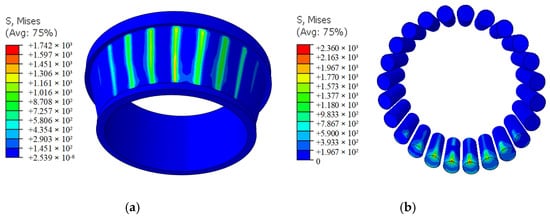
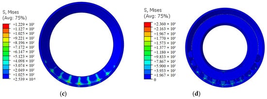
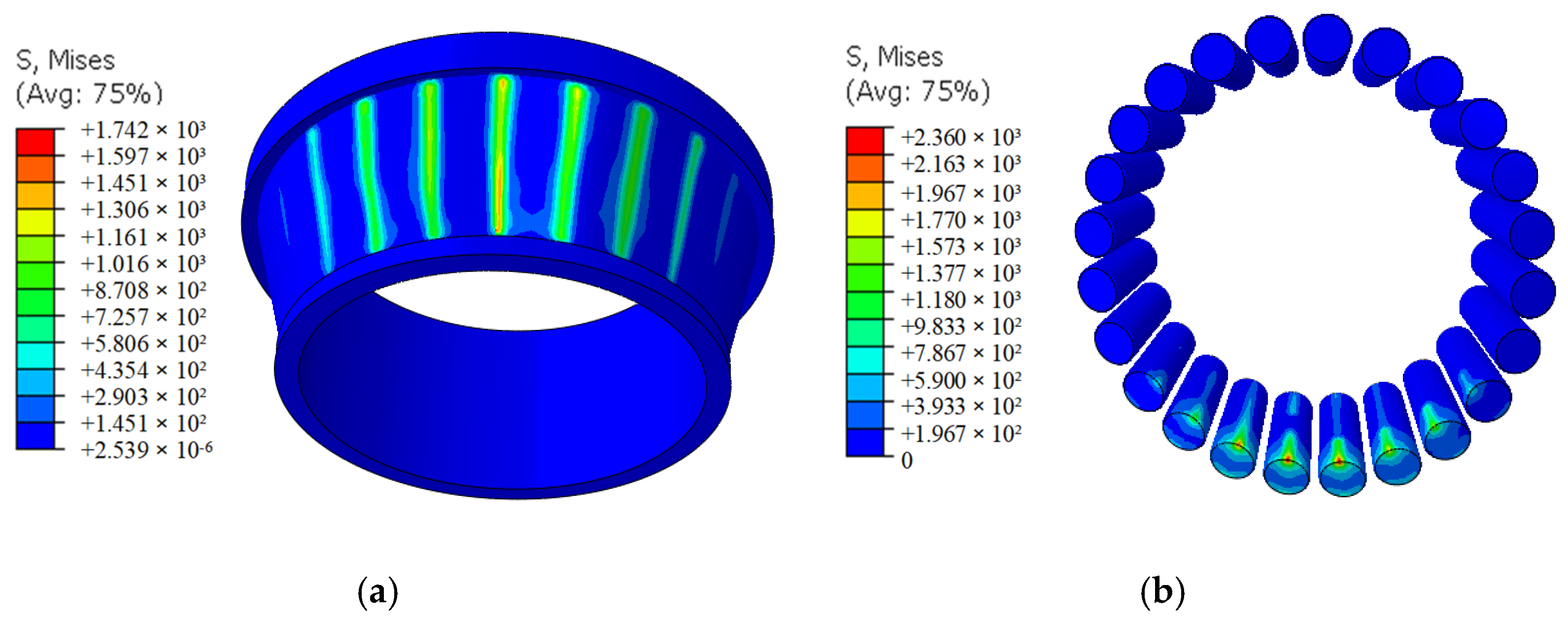
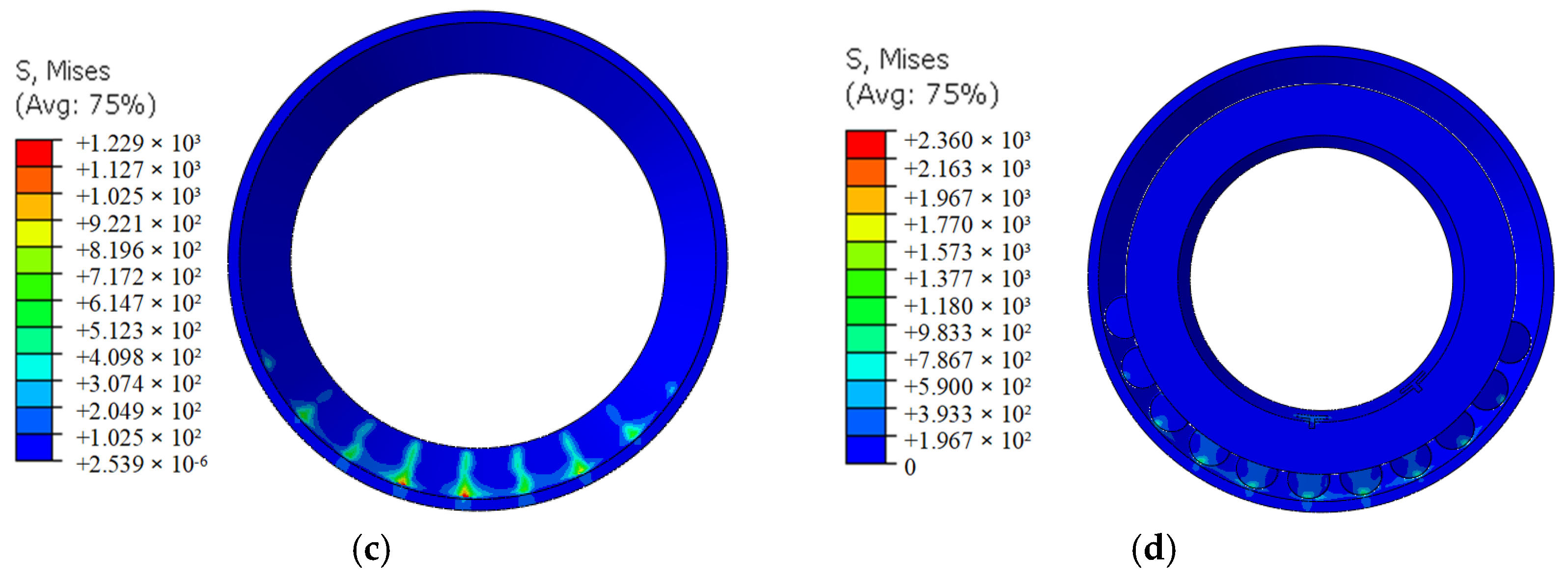
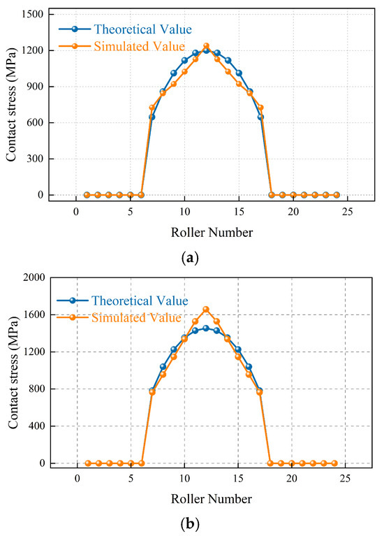
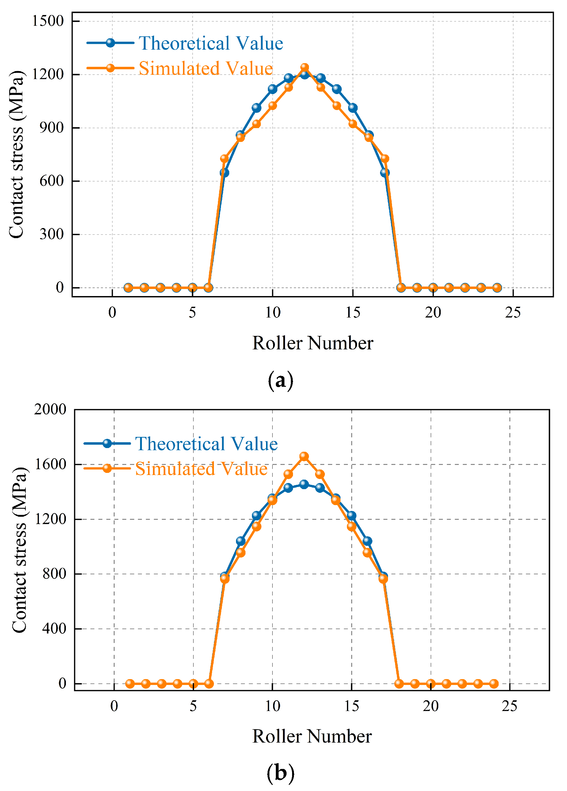
An implicit dynamic analysis was performed using predefined time increments. The outer cylindrical surface of the outer ring was fixed, while the inner ring was coupled to a reference point that permitted only downward translation along the Z-axis, with the remaining five degrees of freedom constrained. The rollers contacted both raceways with a friction coefficient of 0.02. A radial load of 1820 kN, equal to the catalog dynamic radial load rating C1, was applied at the reference point as a common reference load for the fracture analysis; it was not used as the operating load in the ISO 281 calculation. The resulting stress distribution and its comparison with the theoretical contact stresses are presented in Figure 5 and Figure 6, respectively.
Figure 5.
Bearing stress contour plot. (a) Bearing inner ring stress; (b) bearing rolling element stress; (c) bearing outer ring stress; and (d) bearing global stress.
Figure 6.
Comparison of contact stresses in the inner and outer rings. (a) Contact stress comparison of bearing outer ring; (b) contact stress comparison of bearing inner ring.
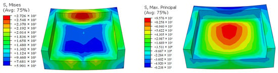
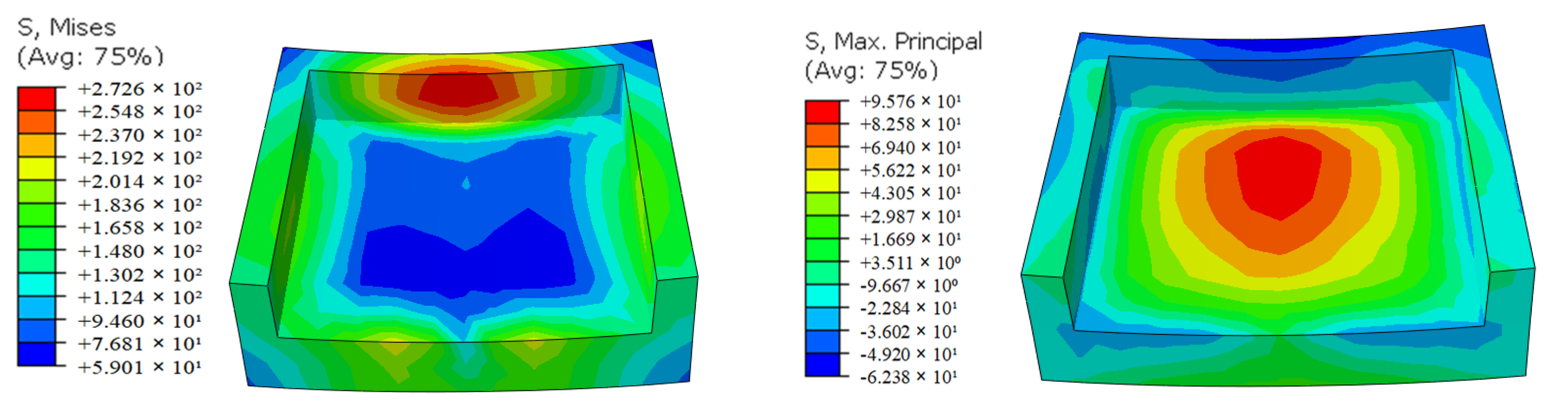
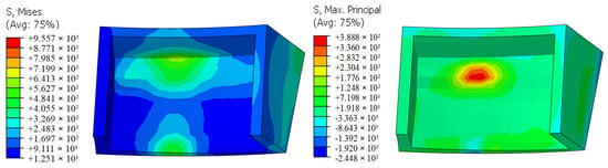
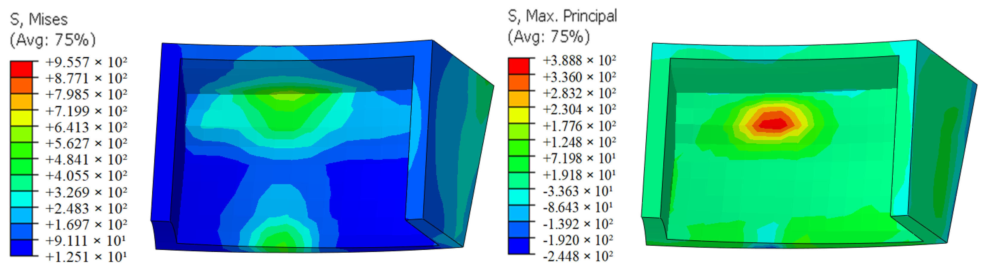
The stress distributions of the rectangular sensor-embedded slots with depths of 6 mm and 15 mm are presented in Figure 7 and Figure 8, respectively. Both sub-models included the complete 30 mm × 30 mm slot, with one 4.5 mm element layer retained on each lateral side and beneath the slot bottom. Their nominal dimensions were therefore approximately 39 mm × 39 mm × 10.5 mm and 39 mm × 39 mm × 19.5 mm, respectively. The maximum principal tensile stress increased from approximately 95.8 MPa for the 6 mm -deep slot to 388.8 MPa for the 15 mm -deep slot, indicating a substantially stronger tensile crack-driving field in the deeper slot.
Figure 7.
Stress contours around the 6 mm-deep sensor—embedded slot.
Figure 8.
Stress contours around the 15 mm-deep sensor—embedded slot.
The global FE analysis provided the complete three-dimensional displacement, stress, and strain fields for the subsequent fracture analysis. The selected regions were adaptively remeshed after crack insertion in FRANC3D and then recombined with the global model. Thus, the original support, loading, and roller-raceway contact conditions were retained. The exposed slot surfaces remained free surfaces, while no tractions or contact interactions were applied to the crack faces.
3.5. Bearing Rating-Life Assessment Under a Representative Operating Condition
The bearing rating life was evaluated according to ISO 281 under a representative constant operating condition. In contrast to the 1820 kN FE reference load, the ISO 281 calculation used the representative operating loads Fr = 600.43 kN and Fa = 775.69 kN to determine the equivalent dynamic bearing load.
Using the catalog values and , giving kN. For a roller bearing, the basic rating life at 90% reliability was calculated as
where kN is the catalog dynamic radial load rating. The resulting life is L10 = 6.318 × 10⁶ revolutions. For 99% reliability, the ISO 281 reliability factor was used:
These ISO rating lives describe the statistical rolling-contact fatigue life of an initially intact bearing and are therefore not directly equivalent to the crack-propagation life obtained from the predefined-crack fracture-mechanics model.
4. Fatigue Crack-Propagation Analysis Based on Fracture Mechanics
4.1. Effects of Slot Depth and Initial Crack Angle on SIFs
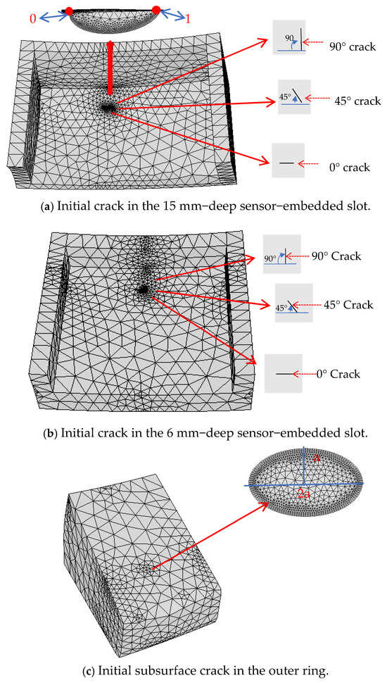
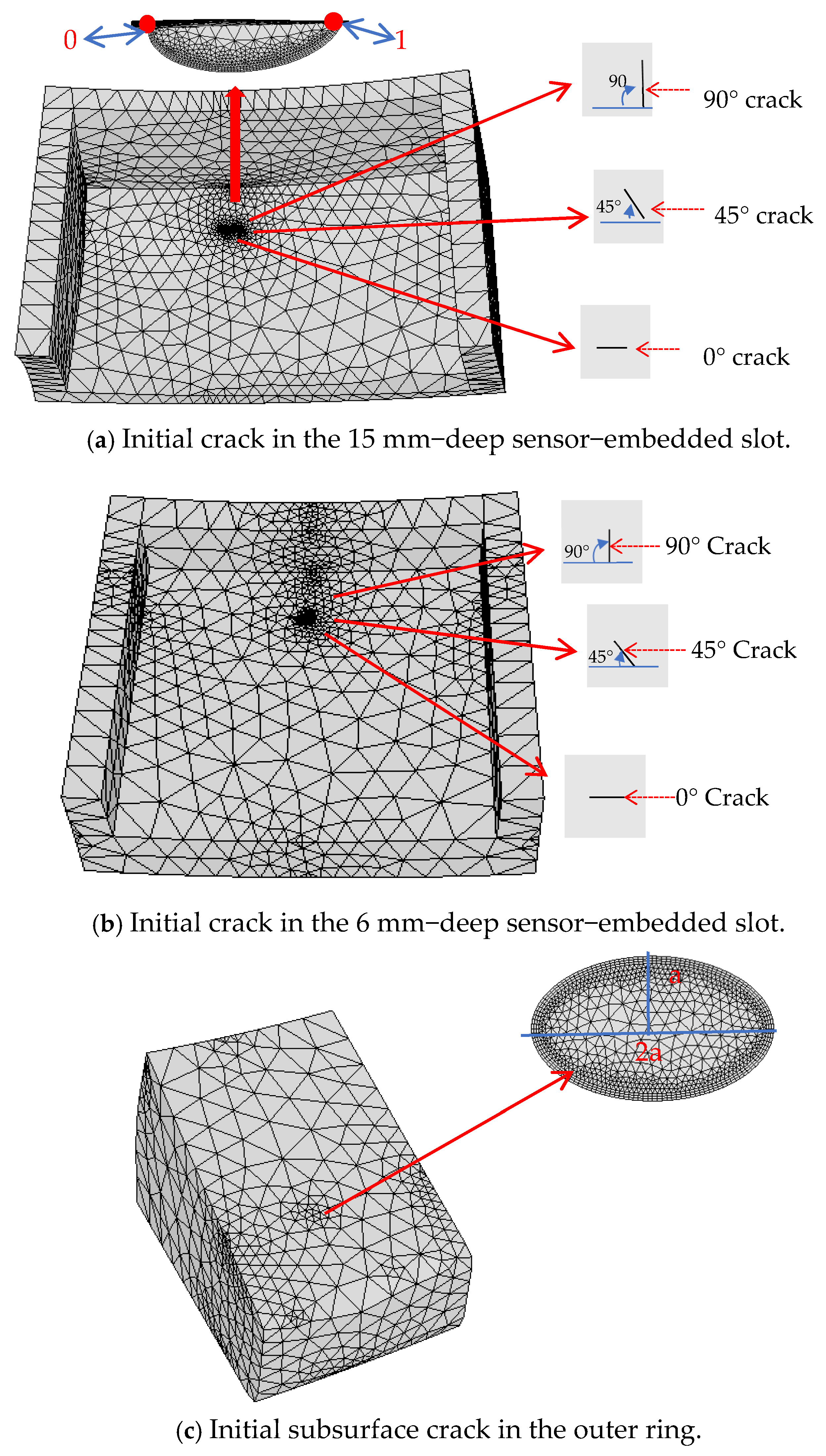
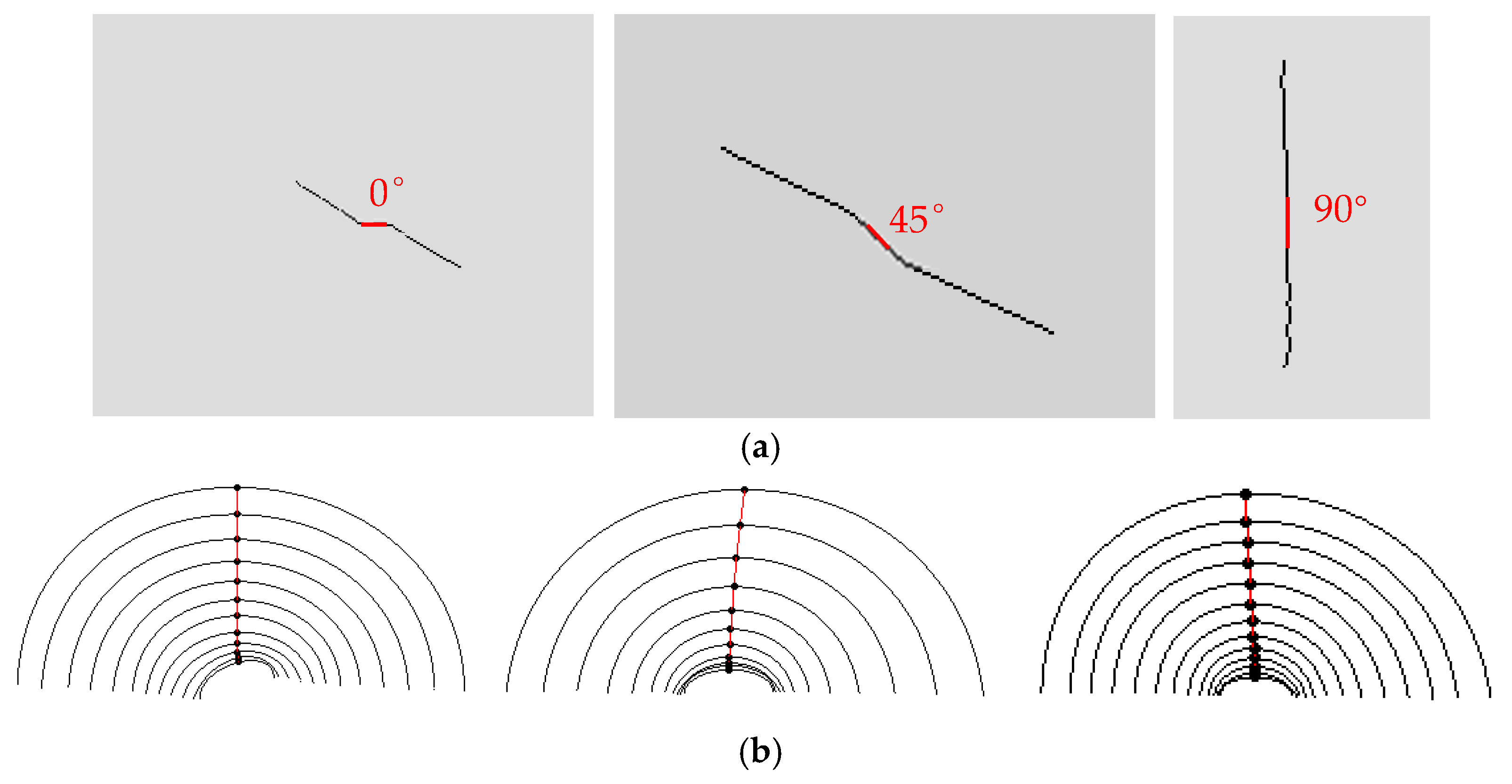
To investigate the effects of the slot depth and initial crack orientation on propagation, adaptive sub-model remeshing was used for the cracked regions. With reference to the semi-elliptical flaw idealization adopted in IIW [24] and BS 7910 [25], surface cracks with initial orientations of 0°, 45°, and 90° were introduced into the 6 mm- and 15 mm-deep slots. The 0° and 90° cases represent the two limiting orientations, while the 45° case provides an intermediate condition. Both the semi-elliptical surface cracks and the elliptical subsurface crack had major and minor axes of 0.1 and 0.05 mm, respectively. The subsurface crack was located 0.5 mm beneath the outer-ring raceway. After crack insertion, FRANC3D automatically generated a locally refined mesh using C3D15 wedge elements along the crack front and C3D10 tetrahedral and C3D20 brick elements in the surrounding transition region.
The crack-front template used three radial rings and eight circumferential subdivisions. Its initial radius was 0.006 mm and varied within approximately 0.004–0.007 mm during adaptive remeshing. Figure 9 presents the initial crack configurations and locally refined meshes, with the crack-front coordinate normalized from 0 to 1.
Figure 9.
Adaptively refined sub-model meshes and initial crack configurations: (a) slot-surface cracks in the 15 mm-deep slot and enlarged semi-elliptical crack mesh; (b) slot-surface cracks in the 6 mm-deep slot; and (c) subsurface elliptical crack and enlarged crack-front mesh.
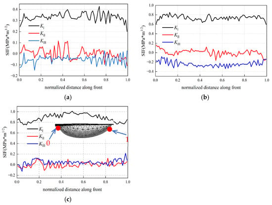
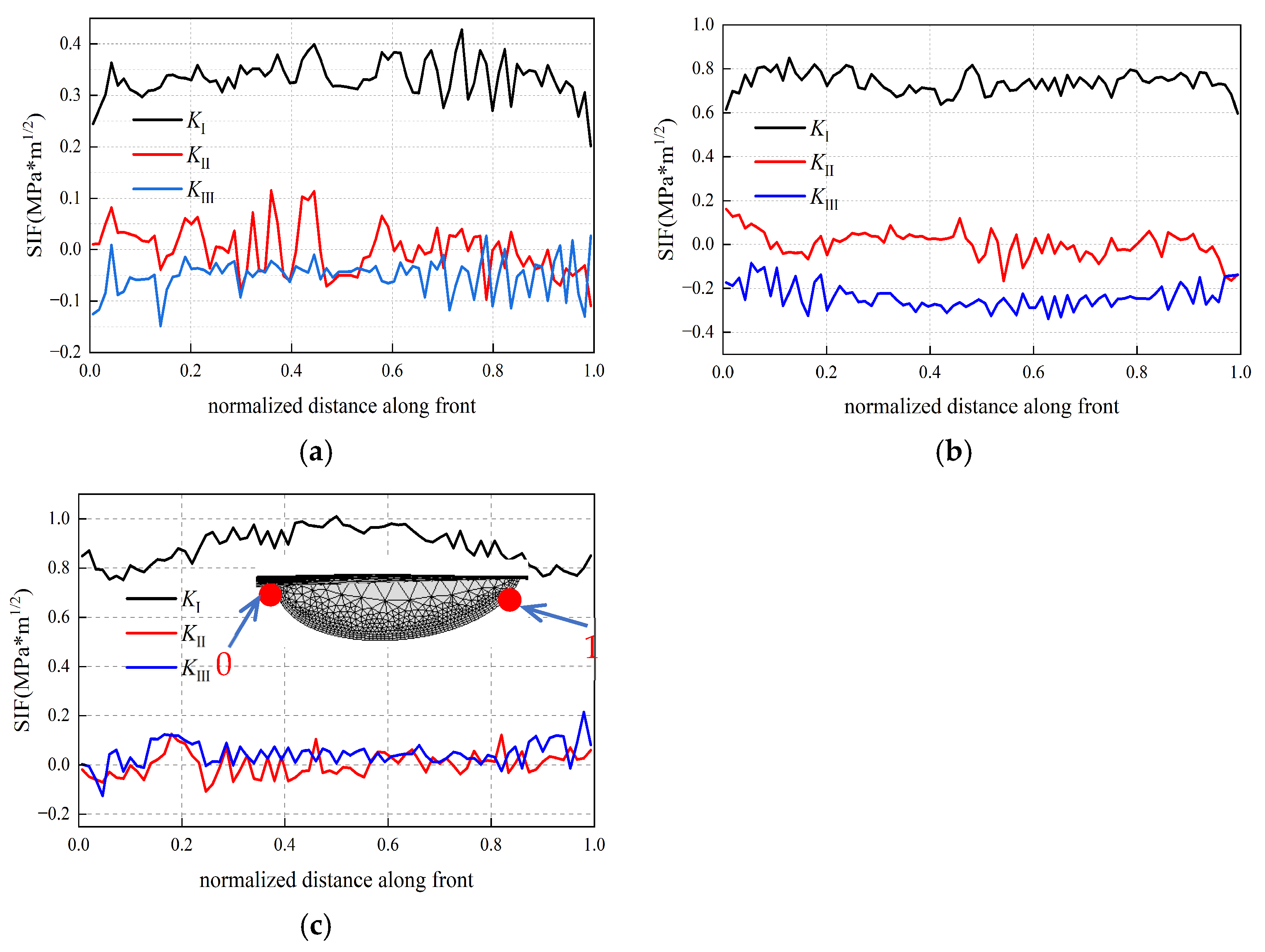
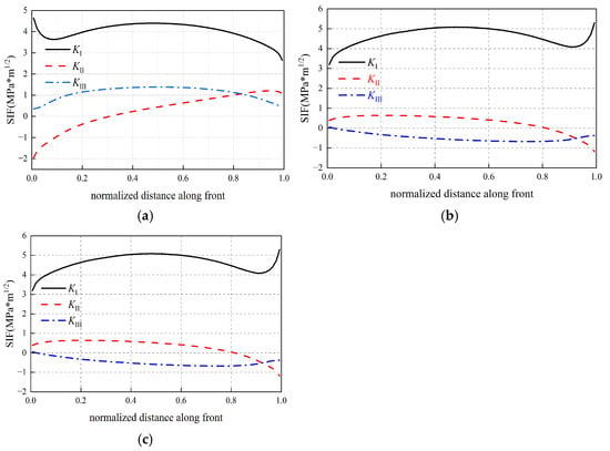
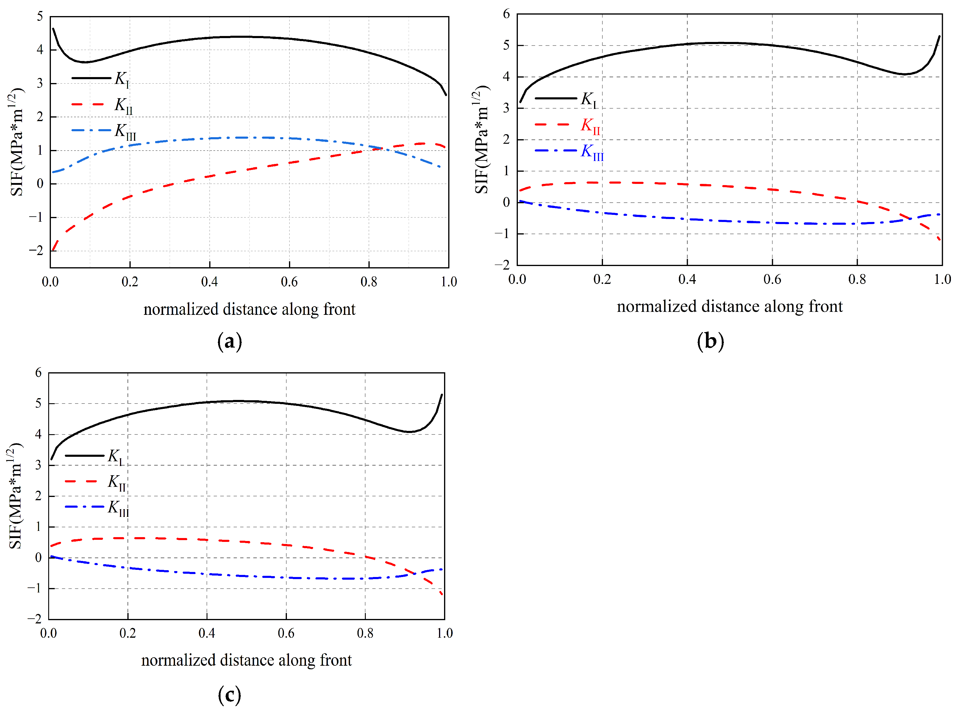
In this study, the SIFs for various initial crack configurations were first evaluated. As shown in Figure 10 and Figure 11, for both the 6 mm and 15 mm slot depths, the KII and KIII values corresponding to different crack angles were substantially lower than KI, which is consistent with the findings of Luo [26]. Notably, at the 6 mm slot depth, the SIFs exhibited irregular fluctuations for different initial crack angles. This was attributed to the fact that the slot was relatively distant from the bearing raceway, where the applied load was low and the local stress field was highly complex.
Figure 10.
SIFs of initial cracks in the 6 mm-deep sensor-embedded slot. (a) 0° initial crack; (b) 45° initial crack; and (c) 90° initial crack.
Figure 11.
SIFs of initial cracks in the 15 mm-deep sensor-embedded slot. (a) 0° initial crack; (b) 45° initial crack; and (c) 90° initial crack.
Furthermore, for both slot depths, KI increased progressively with increasing initial crack angle, indicating that the slot-surface cracks are Mode I-dominated mixed-mode cracks. Accordingly, the subsequent discussion focuses primarily on KI, while all three SIF components remain included in ΔKeq for the crack-growth-rate calculation.
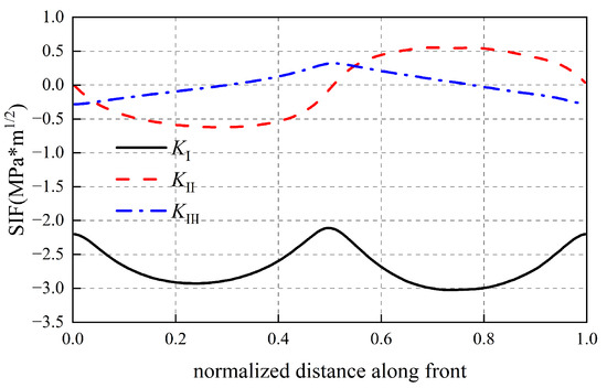
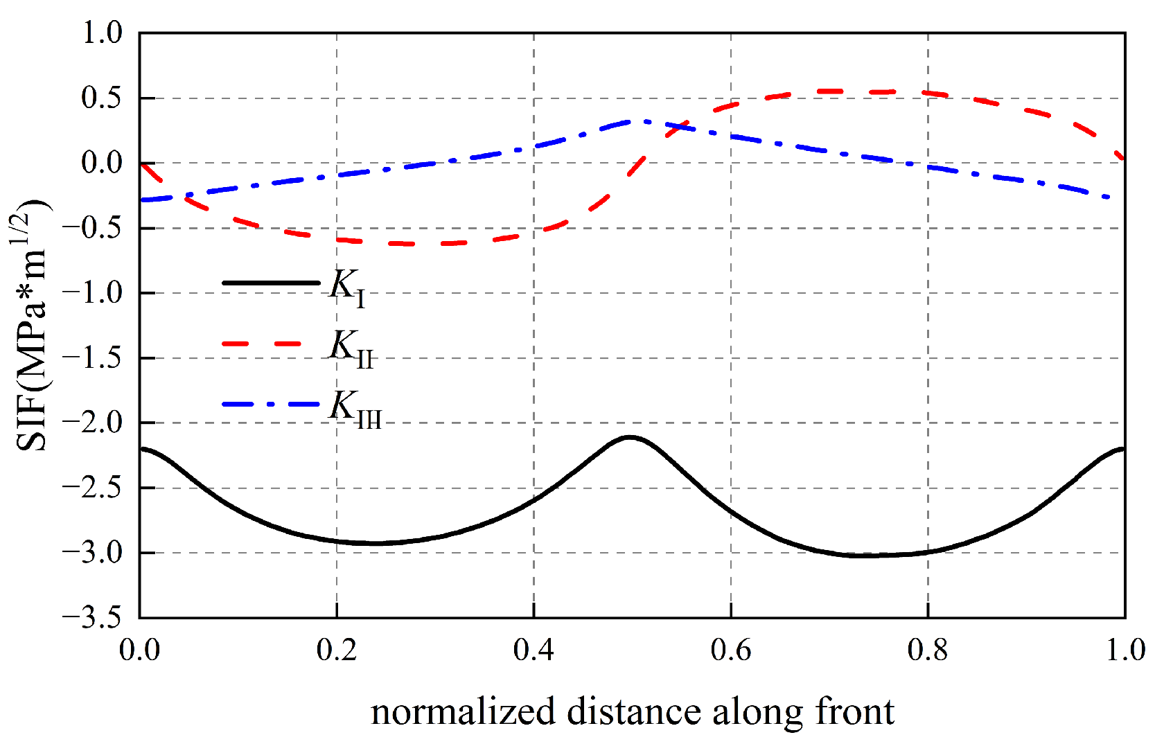
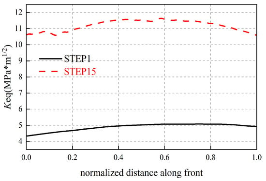
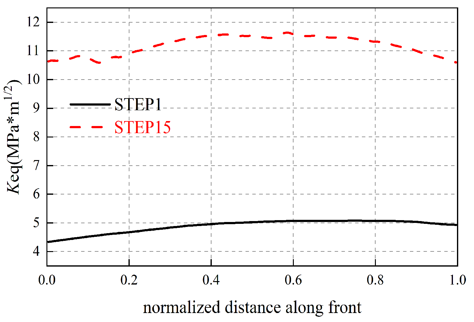
The SIFs computed for the initial subsurface crack (0.5 mm beneath the outer ring raceway) differed markedly from the previous results. As shown in Figure 12, KI at the crack tip consistently exhibited negative values, while KII and KIII alternated between positive and negative along the crack tip. This behavior was attributed to the shear-dominated stress state in the subsurface region of the outer ring. The equivalent SIF, which reflects the combined effect of the stress field at the mixed-mode crack tip, is a key parameter for assessing the crack-propagation risk and predicting the growth direction and critical conditions. As clearly shown in Figure 13, the equivalent SIF for the subsurface crack increased progressively with crack growth, indicating an accelerating crack-propagation rate.
Figure 12.
SIFs of the initial subsurface crack in the outer ring.
Figure 13.
Equivalent SIFs of the initial subsurface crack in the outer ring.
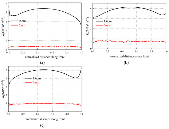
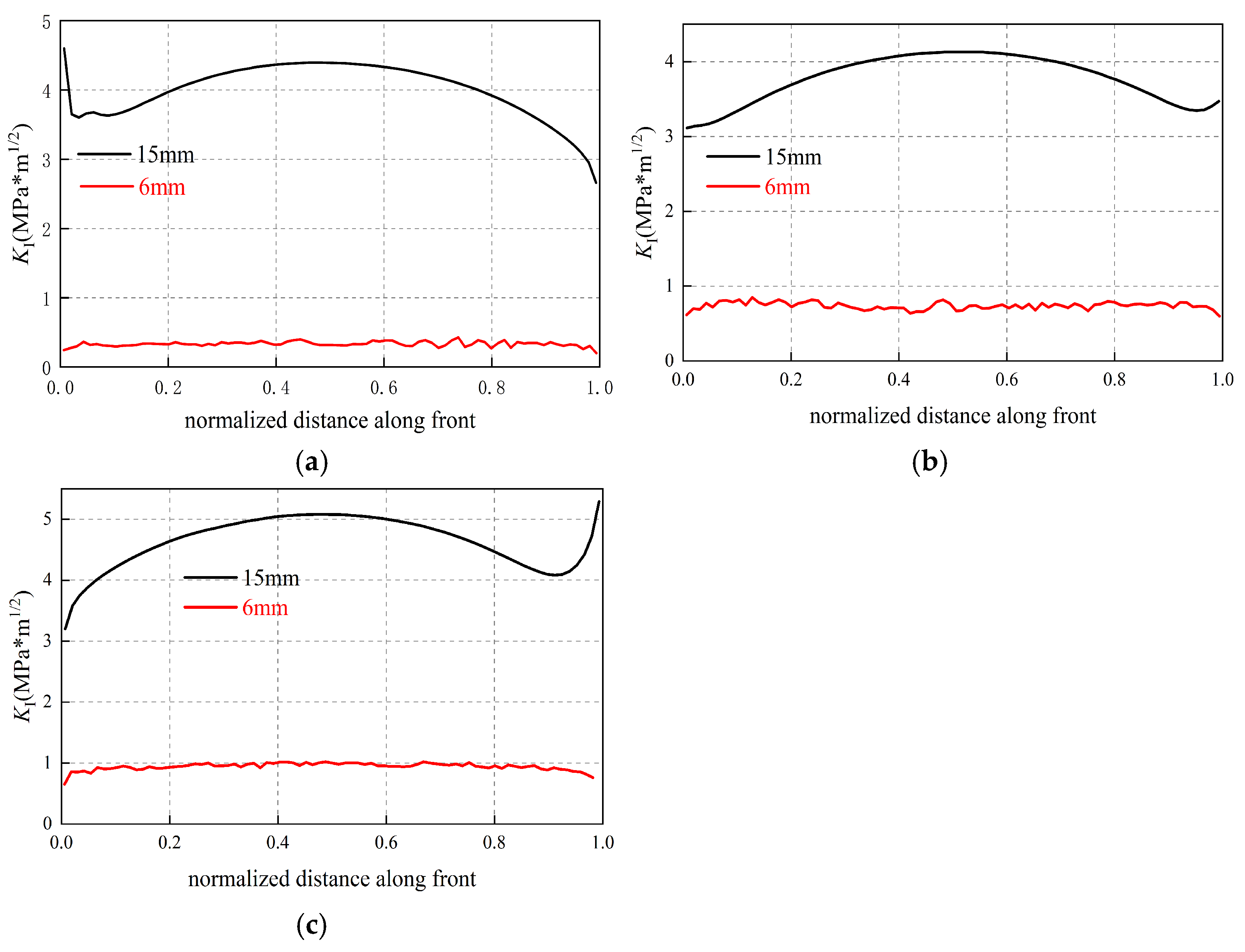
Figure 14 compares KI for initial cracks at different angles in the 6 and 15 mm-deep sensor-embedded slots. Increasing the slot depth from 6 to 15 mm consistently increased KI at all initial crack angles because of the higher local stress in the deeper slot, in agreement with the results in Section 3.4. KI also increased with the initial crack angle, and this trend is examined further in the subsequent crack-propagation analysis.
Figure 14.
Comparison of SIF KI for sensor-embedded slots at different depths. (a) 0° initial crack; (b) 45° initial crack; and (c) 90° initial crack.
4.2. Effect of Crack Propagation on SIFs
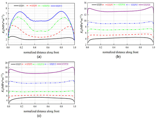
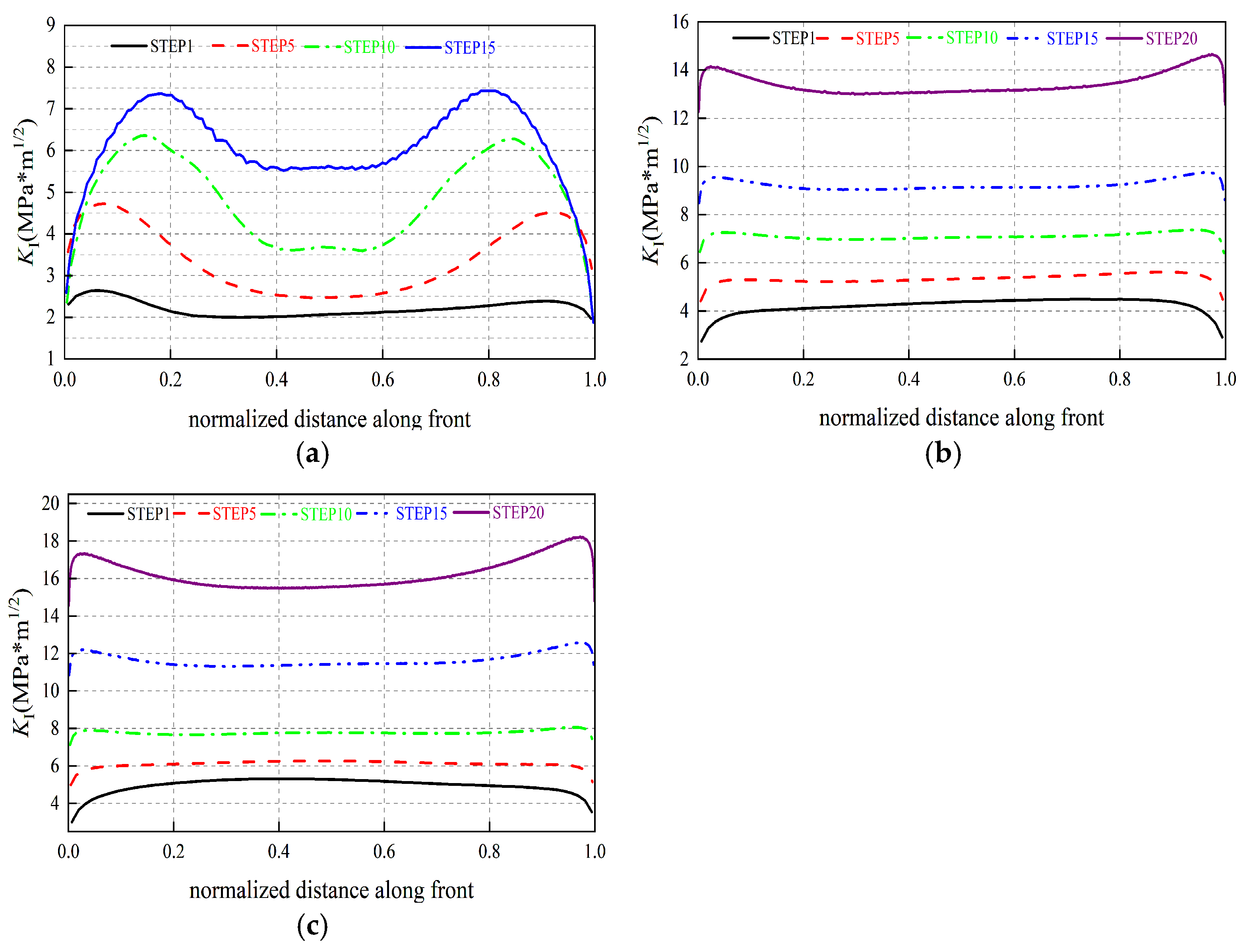
In Figure 15 and Figure 16, “Step n” denotes the nth numerical crack-growth increment rather than an Abaqus load step or a fixed number of loading cycles. At each increment, the SIFs were evaluated, the local growth directions were determined using the MTS criterion, and the crack front was extended, remeshed, and re-analyzed. For clarity, only Step 1 and every fifth increment thereafter are shown.
Figure 15.
Propagation-induced evolution of SIFs for cracks at different angles in the 15 mm-deep sensor-embedded slot. (a) Initial crack at 0°; (b) initial crack at 45°; and (c) initial crack at 90°.
Figure 16.
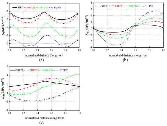
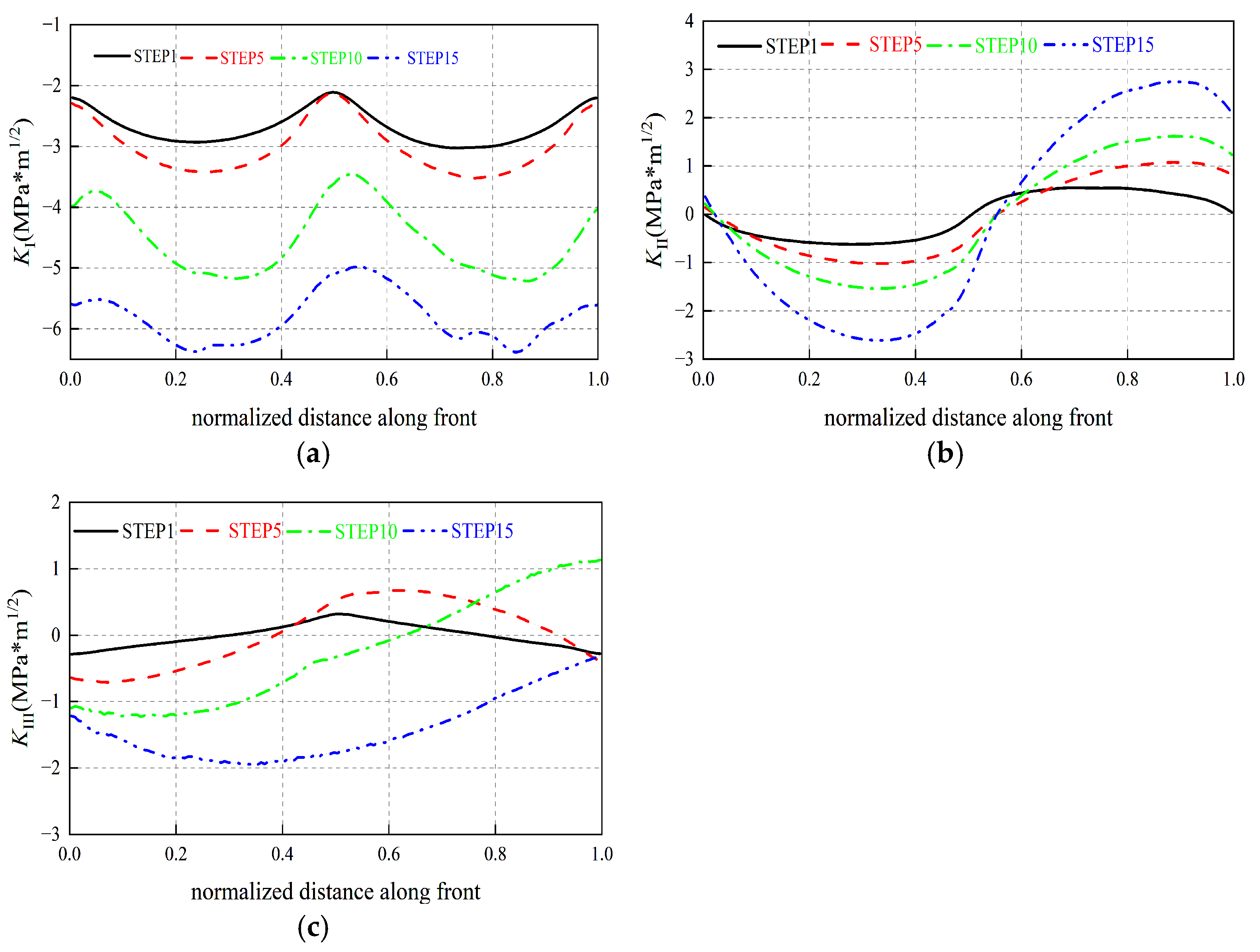
SIF evolution of the propagating subsurface crack in the outer ring. (a) Outer-ring subsurface crack: KI; (b) outer-ring subsurface crack: KII; and (c) outer-ring subsurface crack: KIII.
Under cyclic loading, the initial cracks continued to propagate, accompanied by continuous changes in the SIF at the crack front. Since the SIF trends for the 6 mm and 15 mm sensor-embedded slots were similar, while the SIF values for the 6 mm slot remained consistently lower due to the reduced local stress level, the 15 mm slot was considered more representative for the subsequent crack-propagation analysis and was therefore adopted in this study. Figure 15 presents the evolution of KI for initial cracks at different angles within the 15 mm -deep sensor-embedded slot, recorded at every five propagation steps. The results show that KI at the crack front increased progressively with crack propagation, and a larger initial crack angle consistently yielded a higher KI throughout the propagation process, which is consistent with the trends observed in Figure 14. Notably, for initial crack angles of 45° and 90°, the maximum KI consistently occurred near the crack tip, and this localized concentration became more pronounced with continued propagation. In contrast, for the 0° initial crack, the maximum KI gradually shifted toward the middle of the crack front as the propagation proceeded. Moreover, at Step 15, notable fluctuations in KI along the crack front were observed for the 0° case, suggesting a distinct propagation path compared to the other crack angles—a point that will be further examined in the following section.
Figure 16 shows the evolution of the three SIF components for the outer-ring subsurface crack. Consistent with Cong et al. [27], KI remained negative because of the compressive subsurface stress state and became increasingly negative as the crack propagated [Figure 16a]. In Figure 16b, KII alternates between positive and negative values, whose signs indicate the local shear direction. Its magnitude increases with propagation, particularly near the normalized crack-front coordinates of approximately 0.3 and 0.9. Similarly, the magnitude of KIII increases, although its distribution differs from that of KII, indicating changes in the local torsional component of crack-tip deformation.
Overall, the propagation of the subsurface crack was strongly influenced by Modes II and III. The increasing equivalent SIF shown in Figure 13 is consistent with the accelerating crack-growth rate.
4.3. Effect of Initial Crack Configuration on Crack-Propagation Paths and Life
For cracks emanating from the sensor-embedded slot surface, the evolution patterns for initial cracks at different angles in the 6 mm and 15 mm slots are presented in Figure 17 and Figure 18, respectively. The results reveal that the 0° initial crack exhibited the most pronounced path deviation during propagation, and this deviation tendency diminished as the initial crack angle increased. Moreover, for a given initial crack angle, a deeper slot led to a larger deflection angle, which in turn resulted in a more substantial alteration of the propagation path and a greater reduction in the crack-propagation life.
Figure 17.
Crack evolution in the 6 mm -deep sensor-embedded slot. (a) Crack-propagation paths for different initial crack angles; (b) crack shape evolution for different initial crack angles.
Figure 18.
Crack evolution in the 15 mm -deep sensor-embedded slot. (a) Crack-propagation paths for different initial crack angles; (b) crack shape evolution for different initial crack angles.
The pronounced deviation of the 0° initial crack was mainly caused by the coupled Mode I/II stress field near the slot edge. The rectangular slot and the 1 mm internal fillet radius produced a steep local stress gradient and an asymmetric crack-tip field. Although KI dominated the crack-growth rate, the nonzero KII component affected the local propagation direction. Therefore, the 0° crack deviated from its initial orientation and gradually reoriented toward a tensile-dominated path with a lower shear component. In contrast, the 45° and 90° initial cracks were less sensitive to this turning effect and therefore showed more stable propagation paths. The deeper 15 mm slot further amplified the local tensile-shear gradient, which explains the larger deflection observed at the same initial crack angle. This path-dependent effect explains why the 0° crack exhibited the shortest propagation life, despite its lower local KI: its pronounced deflection exposed the evolving crack front to the steep slot-edge tensile-shear stress gradient throughout a substantial portion of the propagation process.
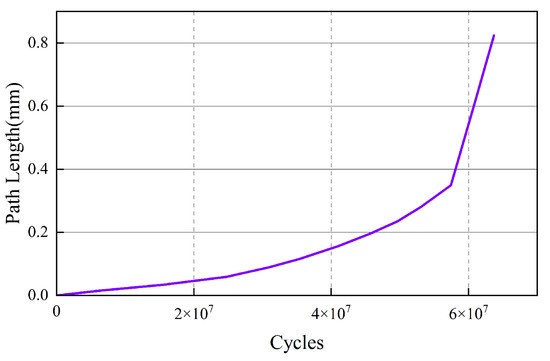
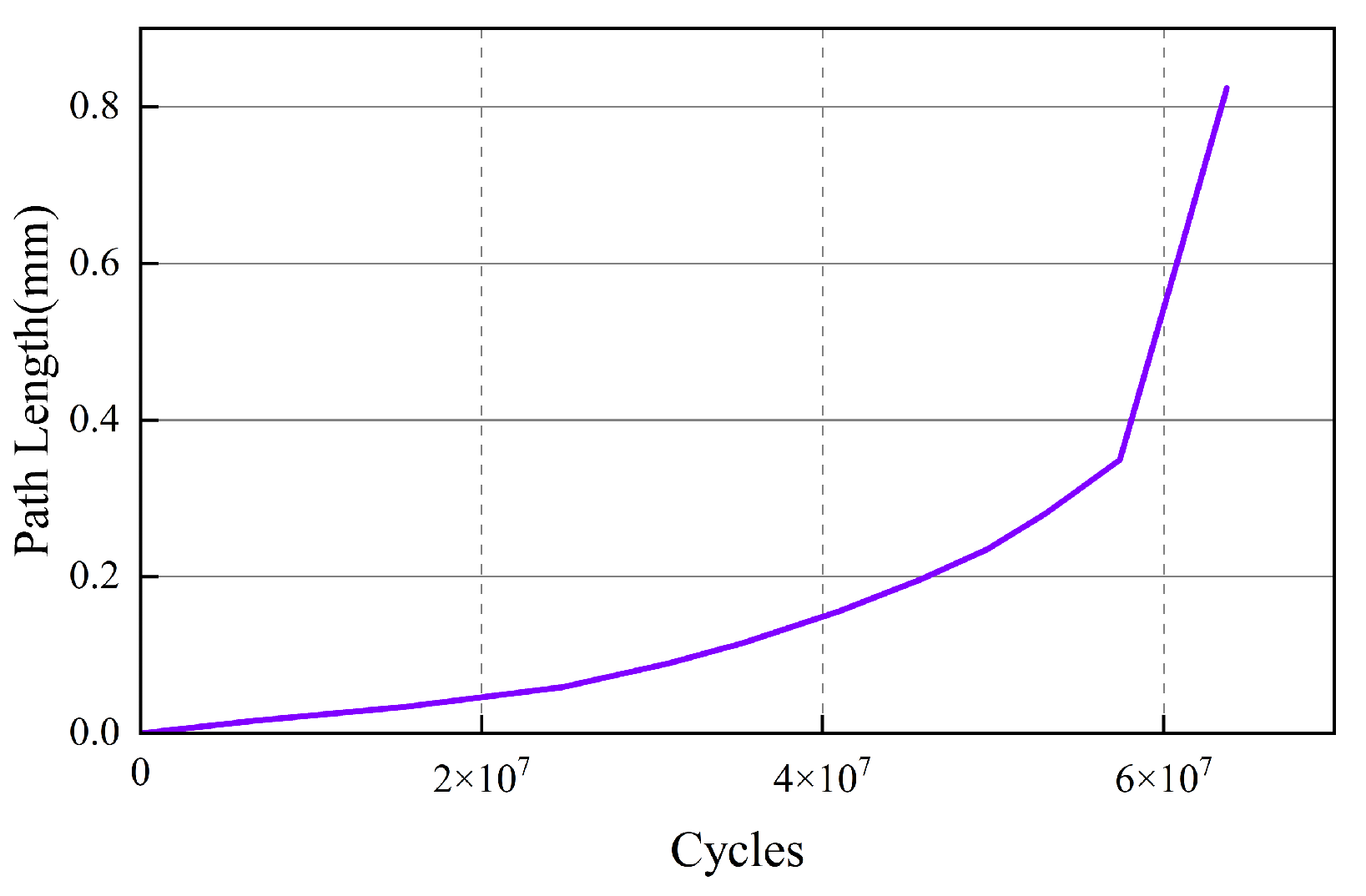
For subsurface cracks beneath the outer-ring raceway, a distinct evolution pattern was observed, as illustrated in Figure 19. The defect initially propagated more slowly along its major axis than along its minor axis. However, as the propagation proceeded, the crack gradually transitioned from an elliptical shape toward a more circular configuration.
Figure 19.
Evolution of the subsurface crack in the outer ring.
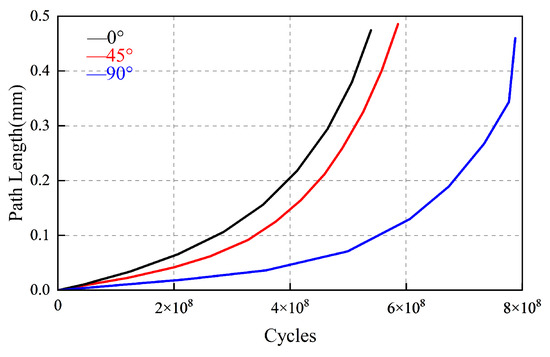
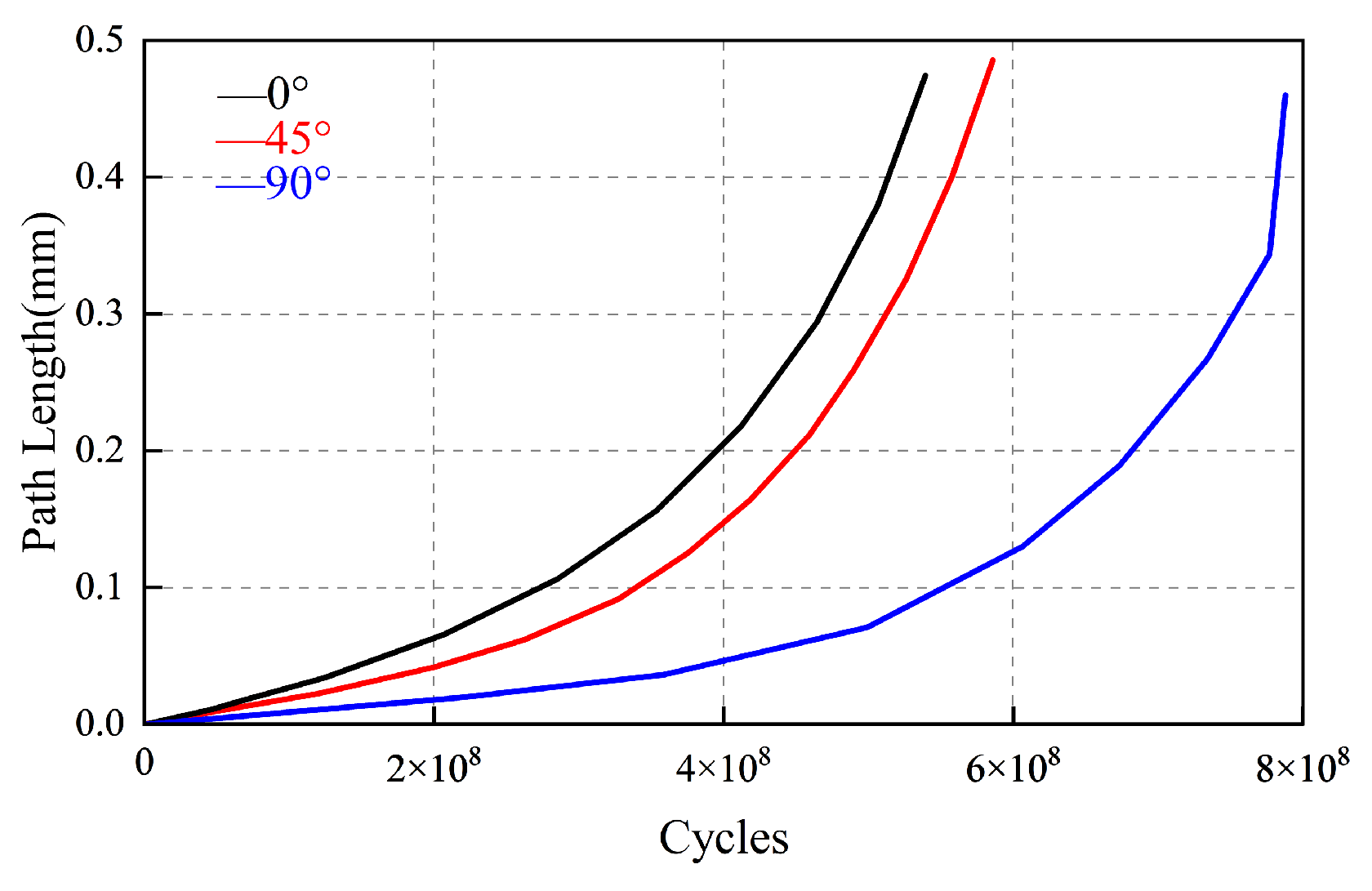
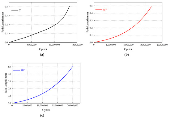
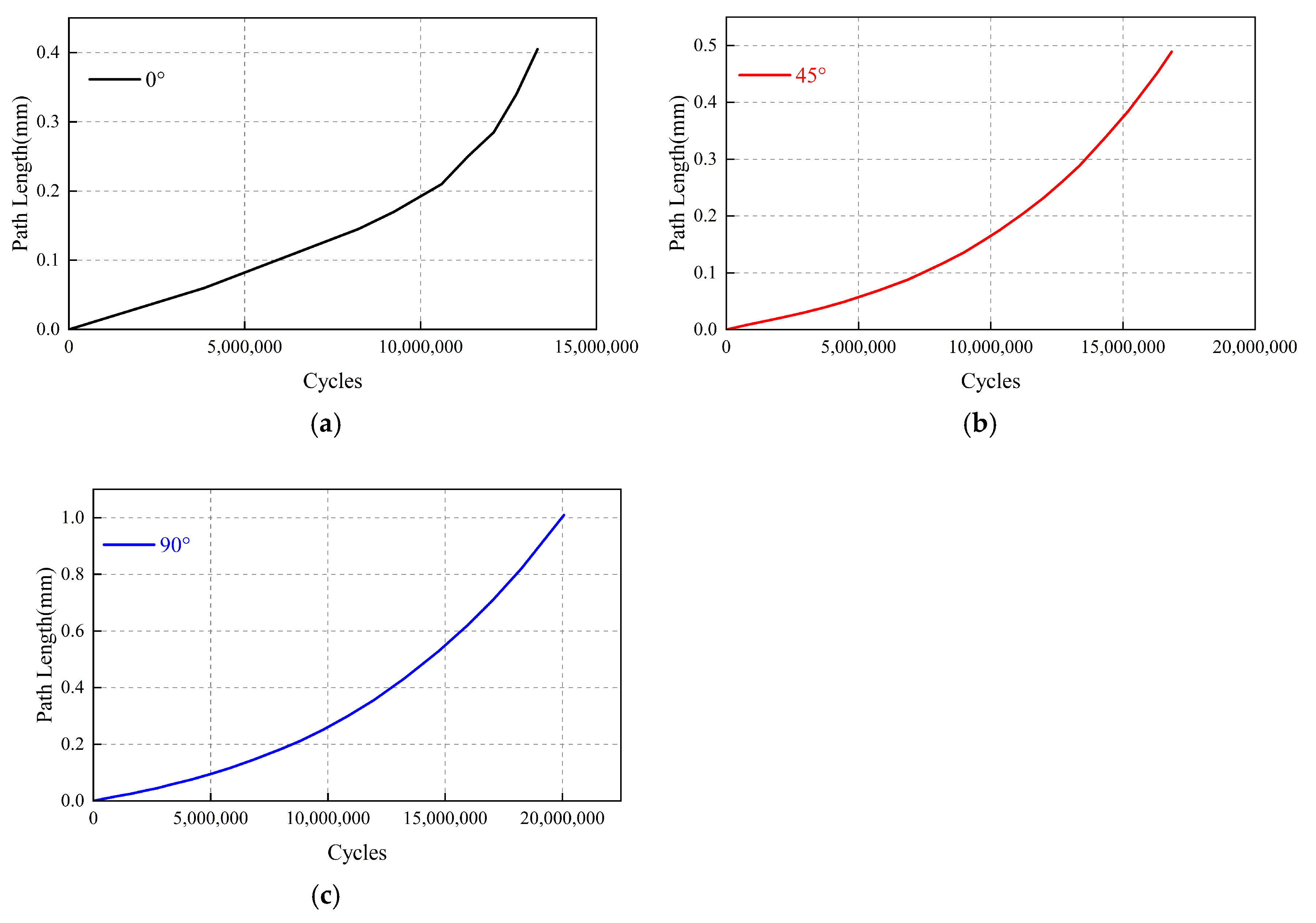
The predicted crack-propagation lives for different initial crack configurations are presented in Figure 20, Figure 21 and Figure 22. Overall, the 6 mm -deep sensor-embedded slot exhibited the longest crack-propagation life, followed by the subsurface crack beneath the outer ring, while the 15 mm -deep sensor-embedded slot showed the shortest life. For all cases, the crack growth rate increased significantly once the crack propagated to approximately 0.2 mm.
Figure 20.
Crack-propagation lives for different initial crack angles in the 6 mm-deep sensor-embedded slot.
Figure 21.
Crack-propagation lives for different initial crack angles in the 15 mm -deep sensor-embedded slot. (a) Crack-propagation life of 0° initial crack; (b) crack-propagation life of 45° initial crack; and (c) crack-propagation life of 90° initial crack.
Figure 22.
Crack-propagation life of the subsurface crack in the outer ring.
Furthermore, the crack-propagation life increased with an increasing initial crack angle, and this trend was consistently observed for both slot depths. For the 6 mm-deep sensor-embedded slot, the minimum crack-propagation life (at a 0° initial crack angle) reached 5.4 × 10⁸ cycles, which is considerably longer than the 6.36 × 10⁷ cycles obtained for the subsurface cracks in the outer ring. For the 15 mm-deep slot, the minimum crack-propagation life was cycles. For reference, the ISO 281 rating lives under the representative constant operating condition are revolutions at 90% reliability and revolutions at 99% reliability. These ISO values are for reference only, as they describe intact-bearing fatigue, while the fracture-mechanics results reflect predefined-crack propagation under the 1820 kN reference FE load.
5. Conclusions
This study investigated the fatigue crack-propagation behavior of electric-shovel top sheave bearings with sensor-embedded slots using adaptive remeshing and finite-element sub-modeling within a fracture-mechanics framework. The effects of the slot depth and the initial crack angle on the SIFs and crack-propagation life were systematically evaluated. The following conclusions were drawn:
- (1)
- Both the slot depth and the initial crack angle significantly affect the stress intensity factor (SIF). Increasing either parameter leads to consistently higher SIF values throughout the crack-propagation process.
- (2)
- Subsurface cracks beneath the outer ring raceway exhibit a distinct evolution pattern compared to cracks originating from the sensor-embedded slot surface. This discrepancy is primarily attributed to the more pronounced influence of shear stress on subsurface crack growth, whereas slot-surface cracking is predominantly tension-driven.
- (3)
- The crack-propagation life decreases with increasing slot depth, but increases with increasing initial crack angle. At each slot depth, the 0° initial crack exhibits the shortest predicted life, whereas the 90° initial crack exhibits the longest. Among the evaluated cases, the 15 mm -deep slot with a 0° initial crack yielded the shortest predicted propagation life, at cycles. This result identifies the slot depth as a key design parameter under the investigated geometry, material properties, loading condition, and slot arrangement.
Design recommendations and limitations: Based on these results, the slot depth should be treated as a key design parameter. Under the present geometry, material properties, loading condition, and slot layout, the 6 mm -deep slot is preferable to the 15 mm-deep slot because it provides a substantially longer crack-propagation life. The local stress concentration may also be reduced by smoothing the slot-edge transition, avoiding abrupt geometric changes, and locating the slot in a relatively low-stress region. However, the fillet radius, slot position and orientation, lead-hole geometry, and local strengthening measures were not independently optimized. Moreover, the shaft and housing were not explicitly modeled; therefore, interference-fit stresses, shaft-deflection-induced load redistribution between the paired bearings, and preload effects were not considered. These recommendations should consequently be regarded as qualitative guidelines for future structural optimization.
Author Contributions
Conceptualization, L.W., F.L., Y.Z. and Y.Y.; Methodology, L.W., F.L. and Y.Y.; Software, F.L. and Y.Y.; Validation, F.L.; Formal Analysis, F.L.; Investigation, L.W. and F.L.; Resources, F.L. and Y.Y.; Data Curation, F.L. and Y.Z.; Writing—Original Draft, F.L. and L.W.; Writing—Review and Editing, L.W., F.L., Y.Z. and Y.Y.; Visualization, F.L. and Y.Z.; Supervision, F.L.; Project Administration, F.L.; Funding Acquisition, L.W. All authors have read and agreed to the published version of the manuscript.
Funding
This work was supported by the National Key R&D Program of China—under grant 2023YFB3406102, and part by the Hunan Natural Science Foundation Project under grants 2025JJ60317 and 2025JJ80228, and part by the Research Project Funded by the Department of Education of Hunan Province under grant 25B0204.
Data Availability Statement
The original contributions presented in this study are included in the article. Further inquiries can be directed to the corresponding author.
Conflicts of Interest
The authors declare no conflicts of interest.
References
- Liu, J.; Li, X.B.; Shi, Z.F. An investigation of contact characteristics of a roller bearing with a subsurface crack. Eng. Fail. Anal. 2020, 116, 104744. [Google Scholar] [CrossRef] [Scilit]
- Li, H.; Lin, J.; Liu, Z.Y.; Jiao, J.Y.; Zhang, B.Y. An interpretable waveform segmentation model for bearing fault diagnosis. Adv. Eng. Inform. 2024, 61, 102480. [Google Scholar] [CrossRef] [Scilit]
- Kunzelmann, B.; Rycerz, P.; Xu, Y.; Arakere, N.K.; Kadiric, A. Prediction of rolling contact fatigue crack propagation in bearing steels using experimental crack growth data and linear elastic fracture mechanics. Int. J. Fatigue 2023, 168, 107449. [Google Scholar] [CrossRef] [Scilit]
- Han, X.; Li, S.; Sun, C.; Lu, S. Modelling micropit formation in rolling contact fatigue of bearings with a crystal plasticity damage theory coupled with cohesive finite elements. Eng. Fract. Mech. 2024, 297, 109873. [Google Scholar] [CrossRef] [Scilit]
- He, H.; Liu, H.; Zhu, C.; Mura, A. Numerical study on fatigue crack propagation behaviors in lubricated rolling contact. Chin. J. Aeronaut. 2021, 34, 24–36. [Google Scholar] [CrossRef] [Scilit]
- He, H.; Chen, Y.; Jin, X.; Liu, H.; Wang, C. Study on predicting rolling contact fatigue of pitch bearing raceway in offshore wind turbine. Int. J. Fatigue 2024, 184, 108284. [Google Scholar] [CrossRef] [Scilit]
- Zhao, L.H.; Li, Q.-C.; Feng, J.-Z.; Zheng, S.-L. Service life prediction method for wheel-hub-bearing under random multi-axial wheel loading. Eng. Fail. Anal. 2021, 122, 105211. [Google Scholar] [CrossRef] [Scilit]
- Zhao, Z.; Wang, X.; Hou, Y. Measurement of the roller tilt angle in a double-row tapered roller bearing with strain gauges. Measurement 2024, 226, 114106. [Google Scholar] [CrossRef] [Scilit]
- Chen, H.; Wang, W.; Liang, H.; Zhang, H. Elastohydrodynamic lubrication analysis of tapered roller bearing considering effect of free ends. Tribol. Int. 2023, 180, 108304. [Google Scholar] [CrossRef] [Scilit]
- Ren, L.; Wang, J.; Yuan, Y.; Wang, B.; Wang, D. Load-carrying performance and fatigue life of double-supported tapered roller bearing in offshore wind turbine. Ocean Eng. 2025, 341, 122451. [Google Scholar] [CrossRef] [Scilit]
- Darmo, S.; Bahiuddin, I.; Handoko, P.; Priatomo, H.R.; Kuncoro, M.; Priyambodo, S.; Haryanto; Rahman, N.F.; Kanosri, A.M.; Winarno, A. Failure analysis of double-row tapered roller bearing outer ring used in Coal Wagon Wheelset. Eng. Fail. Anal. 2022, 135, 106153. [Google Scholar] [CrossRef] [Scilit]
- Ren, Z.D.; Li, B.Z.; Zhou, Q.Z. Rolling contact fatigue crack propagation on contact surface and subsurface in mixed mode I+II+III fracture. Wear 2022, 506–507, 204459. [Google Scholar] [CrossRef] [Scilit]
- Wang, L.; Liu, F.; Hu, C.; Tang, H. Design optimization of sensor-embedded bearing rings in heavy-duty electric shovel applications via multi-physics coupling analysis and experimental validation. Machines 2025, 13, 1008. [Google Scholar] [CrossRef] [Scilit]
- Amato, D.; Mayrhofer, L.; Robl, C.; Dhondt, G.; Citarella, R. Prediction of the crack growth propagation direction in non-proportional mixed-mode missions. Int. J. Fatigue 2023, 166, 107233. [Google Scholar] [CrossRef] [Scilit]
- Hertz, H. On the contact of rigid elastic solids and on hardness. In Assorted Papers; Hertz, H., Ed.; MacMillan: New York, NY, USA, 1882. [Google Scholar]
- Harris, T.A.; Crecelius, W.J. Rolling Bearing Analysis; Wiley: New York, NY, USA, 1986; pp. 149–150. [Google Scholar]
- Wu, Z.; Jakubczak, H.; Glinka, G.; Molski, K.; Nilsson, L. Determination of stress intensity factors for cracks in complex stress fields. Arch. Mech. Eng. 2003, 50, 41–67. [Google Scholar]
- Moës, N.; Dolbow, J.; Belytschko, T. A finite element method for crack growth without remeshing. Int. J. Numer. Methods Eng. 1999, 46, 131–150. [Google Scholar] [CrossRef] [Scilit]
- Cherepanov, G.P. On crack propagation in solids. Int. J. Solids Struct. 1969, 5, 863–871. [Google Scholar] [CrossRef] [Scilit]
- Fracture Analysis Consultants, Inc. FRANC3D User’s Manual; Fracture Analysis Consultants, Inc.: Ithaca, NY, USA, 2022. [Google Scholar]
- Chen, Y.M.; Jin, X.; Yue, Y.; Wang, S.; Han, H.; Wen, M.; Wang, Q.; Cheng, P. Investigation on 3D fatigue crack propagation in pitch bearing raceway of offshore wind turbines. Ocean Eng. 2023, 269, 113524. [Google Scholar] [CrossRef] [Scilit]
- Paris, P.; Erdogan, F. A critical analysis of crack propagation laws. J. Basic Eng. 1963, 85, 528–533. [Google Scholar] [CrossRef] [Scilit]
- GB/T 6398-2017; Metallic Materials-Fatigue Tests-Fatigue Crack Propagation Methods. Standards Press of China: Beijing, China, 2017.
- IIW-1823-07; Recommendations for Fatigue Design of Welded Joints and Components. IIW: Paris, France, 2008.
- BS 7910:2019; Guide to Methods for Assessing the Acceptability of Flaws in Metallic Structures. British Standards Institution: London, UK, 2019.
- Luo, Y.; Liu, X.; Cui, J.; Wang, H.; Huang, L.; Zeng, W.; Zhang, H. Lifetime fatigue cracking behavior of weld defects in orthotropic steel bridge decks: Numerical and experimental study. Eng. Fail. Anal. 2025, 167, 108993. [Google Scholar] [CrossRef] [Scilit]
- Cong, T.; Liu, X.; Wu, S.; Zhang, G.; Chen, E.; Qian, G.; Berto, F. Study on damage tolerance and remain fatigue life of shattered rim of railway wheels. Eng. Fail. Anal. 2021, 123, 105322. [Google Scholar] [CrossRef] [Scilit]

Disclaimer/Publisher’s Note: The statements, opinions and data contained in all publications are solely those of the individual author(s) and contributor(s) and not of MDPI and/or the editor(s). MDPI and/or the editor(s) disclaim responsibility for any injury to people or property resulting from any ideas, methods, instructions or products referred to in the content. |
© 2026 by the authors. Licensee MDPI, Basel, Switzerland. This article is an open access article distributed under the terms and conditions of the Creative Commons Attribution (CC BY) license.