


Abstract
Electric power steering (EPS) motors require low torque ripple, low cogging torque, and smooth torque output to ensure precise control and driving comfort. However, consequent pole permanent magnet synchronous motors (CP-PMSMs), although advantageous in reducing permanent magnet usage, exhibit an imbalanced magnetic flux distribution due to the iron poles, resulting in even-order harmonic components in the back electromotive force (BEMF) and significant torque ripple. In this paper, a rotor pole arrangement for CP-PMSMs is proposed to improve torque characteristics for EPS applications. Symmetric and asymmetric pole arrangements are introduced to modify the magnetic flux distribution and suppress harmonic components generated by the iron poles. In addition, the iron pole arc ratio is selected as a key design variable and analyzed for each model to achieve low torque ripple while maintaining torque performance. The electromagnetic characteristics of the proposed structures are evaluated using finite element analysis under identical operating conditions. The results show that the torque ripple of the proposed models is reduced by approximately 33.3%p and 34.1%p compared with the conventional CP-PMSM, and the cogging torque is also significantly reduced. Although average torque decreases, overall torque characteristics improve due to reduced torque ripple and harmonic components. These results demonstrate that the proposed rotor pole arrangement effectively enhances torque quality in CP-PMSMs without increasing axial length or requiring three-dimensional analysis.
1. Introduction
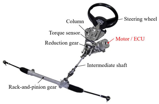
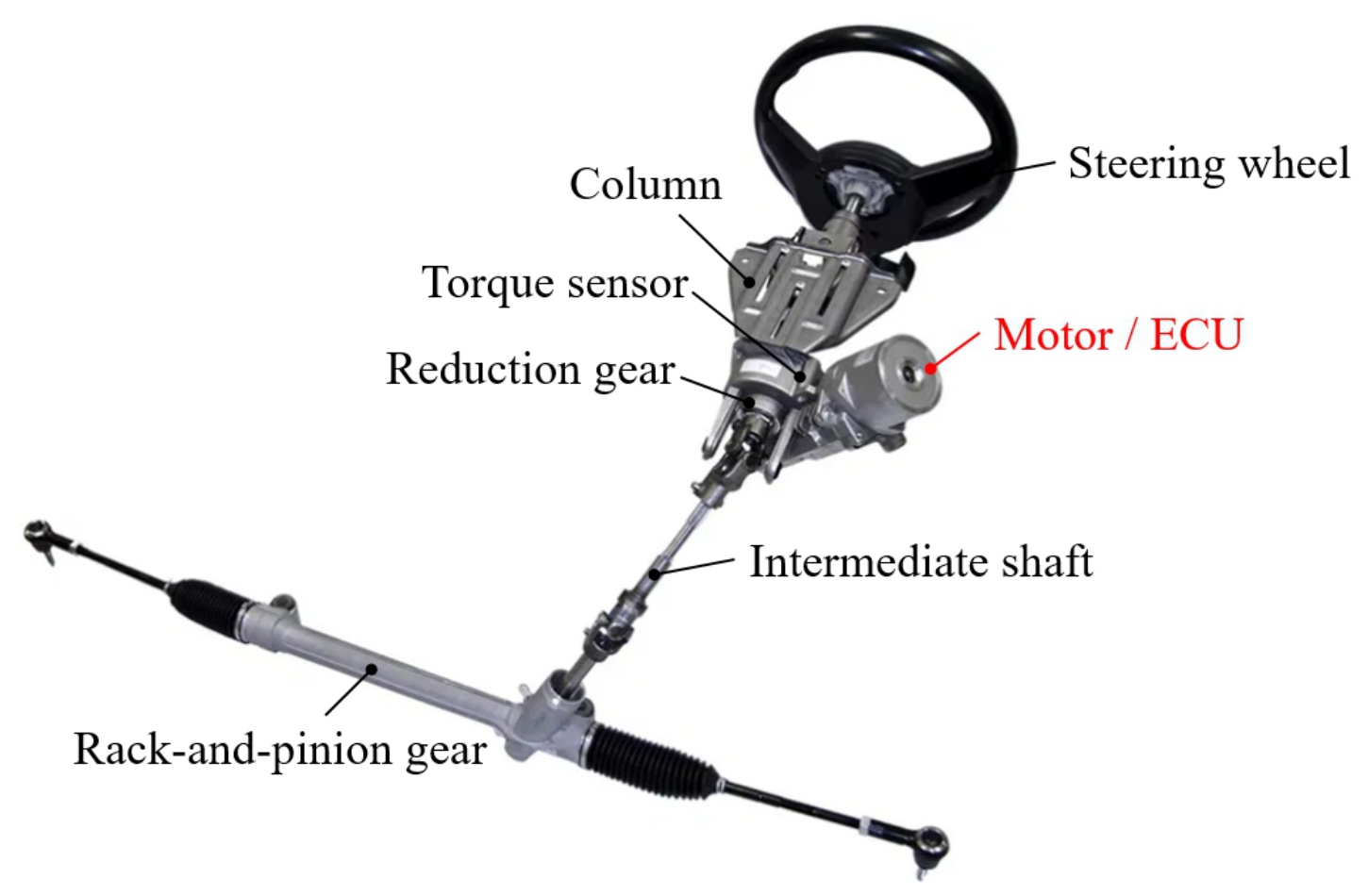
Permanent magnet synchronous motors (PMSMs) are widely used in automotive applications due to their high efficiency, high torque density, and compact design [1,2,3,4]. Most PMSMs employ rare-earth permanent magnets because of their high magnetic flux density and superior output capability, which contribute to the high torque density. Although rare-earth permanent magnets offer a high magnetic flux density, they pose the challenges of limited resources and supply instability, leading to significant price fluctuations [5,6,7,8]. To overcome these, reducing the amount of permanent magnet has become an important research topic in motor design. One of the topologies to reduce permanent magnet utilization is the consequent pole permanent magnet synchronous motor (CP-PMSM), in which one polarity of the rotor poles is replaced with an iron pole. However, the magnetic field distribution becomes asymmetric as one permanent magnet is replaced by the core. This causes even-harmonic components to increase the back electromotive force (BEMF), leading to increased torque ripple and electromagnetic vibration. Since the motor is located near the steering wheel, as shown in Figure 1, this poses challenges for electric power steering (EPS) applications, where low torque ripple and vibration are essential for smooth steering performance and driver comfort [9,10,11].
Figure 1.
Structure of electric power steering system.
Various studies have been conducted to reduce torque ripple and improve the electromagnetic performance of CP-PMSMs. Most previous studies have focused on the shape optimization of permanent magnets and iron poles to reduce the torque ripple [12,13,14,15]. In [16,17,18], various structural modifications, such as pole shifting, unequal airspace design, and stator shape optimization, were also investigated to improve electromagnetic characteristics and reduce torque ripple. However, these approaches mainly rely on geometric modifications and do not fundamentally resolve the asymmetric magnetic flux distribution caused by the iron pole structure. Other studies have investigated the reduction in unipolar end-leakage flux through pole–slot combinations and winding configurations [19]. In [20], a topology that applies consequent poles to a skewed stator and a surface-inserted rotor was proposed to improve torque and reduce cogging torque. Although these methods improve specific performance, they increase design complexity. In EPS applications, low torque ripple is an important requirement because torque pulsation can deteriorate steering feel, vibration, and acoustic noise. Previous studies on surface PMSM-type EPS motors have reported torque ripple levels of approximately 1–2% when additional ripple reduction topologies, such as skew structures or slotless stators, are adopted [9,10]. However, conventional CP-PMSMs with standard slotted stator structures generally exhibit relatively higher torque ripple levels of approximately 12% [12]. Therefore, reducing torque ripple within the CP-PMSM topology itself remains an important challenge for practical EPS motor applications. Since torque ripple in CP-PMSMs is primarily caused by imbalances in magnetic flux density, a configuration combining an N-CP-PMSM and an S-CP-PMSM in the axial direction has been proposed [21]. This approach improves flux symmetry and reduces torque ripple compared with conventional CP-PMSMs. However, it introduces an axial leakage flux, which degrades torque performance. To mitigate this issue, an axial gap between the N-CP-PMSM and S-CP-PMSM rotors is required, which increases manufacturing complexity and computational cost in three-dimensional finite element analysis (3D FEA). Therefore, despite its effectiveness in improving flux symmetry, the axial combination structure is limited by its increased structural complexity and reliance on three-dimensional design and analysis. Unlike the axial combination structure in [21], the proposed method achieves flux symmetry improvement through circumferential pole arrangement within a single 2D rotor structure, without requiring axial stacking or three-dimensional analysis. In this study, a two-dimensional rotor pole arrangement is proposed to achieve a similar flux redistribution effect without increasing axial length or requiring three-dimensional analysis, thereby providing a simpler and more practical solution for torque ripple reduction.
In this paper, a novel rotor pole arrangement for CP-PMSMs is proposed to reduce the torque ripple for EPS applications. An electric machine with an eight-pole/12-slot combination for EPS is considered to evaluate the electromagnetic performance for pole arrangement. By rearranging the N, S, and iron poles with a two-dimensional (2D) rotor structure, the magnetic flux distribution changes, reducing harmonics and torque ripple. The proposed structures are classified as symmetric and asymmetric according to the pole arrangement, and their electromagnetic performance is evaluated using finite element analysis (FEA) in ANSYS Maxwell 2024R1. In the proposed structures, a segmented rotor configuration is adopted to mitigate leakage flux paths within the pole arrangement. The torque ripple is analyzed according to the iron pole arc ratio, which is the main design parameter to reduce the torque ripple. The optimal iron pole arc ratio is designed for each model to compare the torque ripple. Compared with the conventional CP-PMSM, the torque ripple of the symmetric and asymmetric CP-PMSMs is reduced by approximately 42.61%p and 41.78%p, respectively, while the average torque decreases by about 14.12% and 8.98%, respectively. As a result, although the proposed method leads to a reduction in average torque, it achieves a significant reduction in torque ripple compared with the conventional CP-PMSM through the pole arrangement.
This paper is organized as follows. Section 2 discusses the conventional CP-PMSM, which uses only the N-pole, and the axial CP-PMSM structure proposed in [21]. Section 3 defines the proposed model by analyzing the electromagnetic characteristics of the proposed symmetric and asymmetric pole arrangement CP-PMSM structures and the defined design variables. Section 4 compares and analyzes the electromagnetic performances of the conventional CP-PMSM and the proposed models using finite element analysis (FEA). Finally, Section 5 concludes this paper.
2. Conventional CP-PMSM
2.1. Characteristic of Conventional CP-PMSM
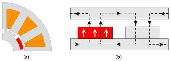
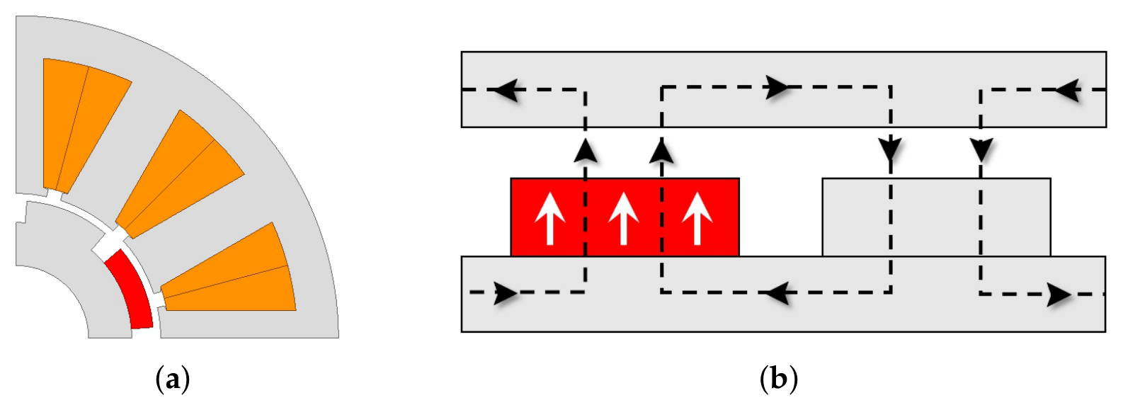
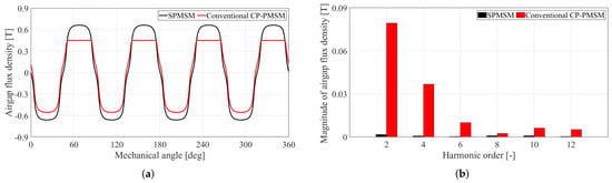
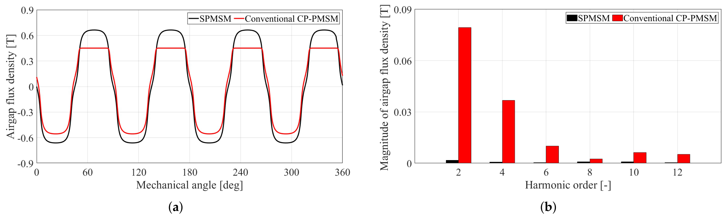
Figure 2a shows the structure of a conventional CP-PMSM. In this structure, a permanent magnet is arranged with one polarity of the rotor poles, and the opposite polarity is an iron pole. The line and arrows of Figure 2b show the magnetic flux and flow direction of magnetic flux. It is generated by the permanent magnet that flows through the rotor core, and through the opposite magnetic pole in the iron pole. Since one rotor pole is formed by an iron pole instead of a permanent magnet, the air-gap flux density becomes asymmetric compared to a conventional surface PMSM (SPMSM), as illustrated in Figure 3a. This asymmetry introduces additional harmonic components in the air-gap flux density, which increases torque ripple and vibration. Figure 3b shows the comparison of the magnitudes of the air-gap flux densities of the SPMSM and conventional CP-PMSM by harmonic order using the fast Fourier transform (FFT). The SPMSM exhibits a larger fundamental component, whereas the conventional CP-PMSM shows higher magnitudes in the remaining harmonics, particularly even-order harmonics. Since these harmonic components induce torque variations and consequently increase torque ripple, mitigating the imbalance in magnetic flux distribution is a critical design consideration for reducing torque ripple in CP-PMSMs.
Figure 2.
Conventional CP-PMSM: (a) 2D shape and (b) magnetic flux path on cross-section.
Figure 3.
Air-gap flux density of SPMSM and conventional CP-PMSM: (a) waveform of air-gap flux density and (b) fast Fourier transform of air-gap flux density.
2.2. Axial Combination Design for Torque Ripple Reduction of CP-PMSM
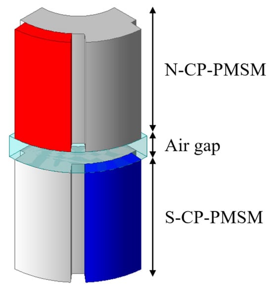
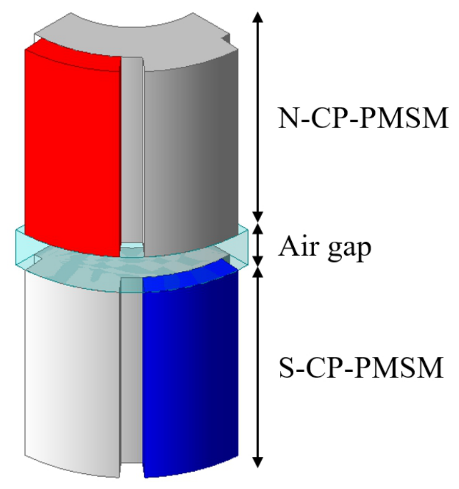
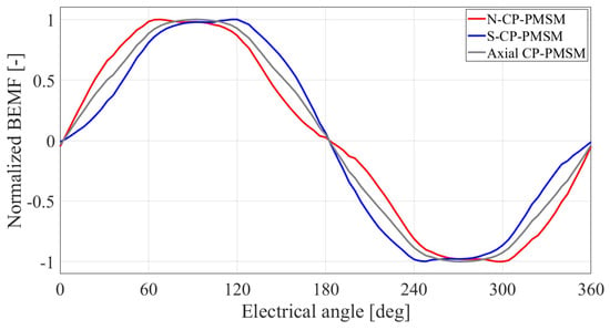
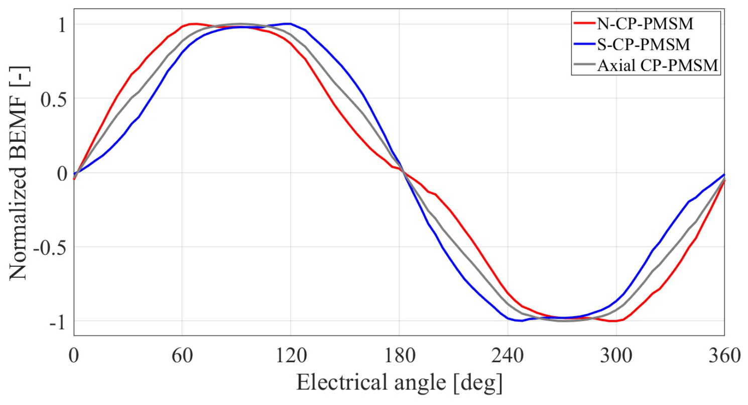
In a previous study [21], an axial combination structure was proposed to improve flux symmetry in CP-PMSMs, as illustrated in Figure 4. In this structure, N-pole and S-pole CP-PMSMs (N-CP-PMSM and S-CP-PMSM) are combined in the axial direction, leading to the elimination of the effect of asymmetry of the air-gap magnetic flux distribution, such as even-order harmonic components. Therefore, the axial combination CP-PMSM allows the even-order harmonic components generated by each CP-PMSM rotor to cancel each other out, thereby improving symmetry and reducing harmonics in the BEMF. Figure 5 shows the comparison of normalized BEMF waveforms of the N-CP-PMSM, S-CP-PMSM, and axial combined CP-PMSM. The BEMF waveform of the axial CP-PMSM is positioned between those of the N-CP-PMSM and S-CP-PMSM, indicating that the harmonic characteristics generated by the two conventional CP-PMSM structures are partially compensated through axial combination. As a result, the even-order harmonics in the BEMF that cause waveform distortion, as illustrated in Figure 5, are eliminated, thereby reducing the torque ripple compared with the conventional CP-PMSM. Although the axial combination structure can reduce the torque ripple, the axial leakage flux can degrade electromagnetic performance. To address this, an axial air gap should be added between the N-CP-PMSM and S-CP-PMSM, increasing the motor’s axial length and requiring 3D finite element analysis, which significantly increases computational time and manufacturing complexity. Therefore, although the axial CP-PMSM effectively reduces torque ripple by improving flux symmetry, its increased axial length and the requirement for 3D analysis limit its practical application. This paper focuses on improving flux symmetry within a 2D structure without increasing axial length or requiring 3D analysis.
Figure 4.
Structure of axial CP-PMSM.
Figure 5.
Comparison of normalized BEMF waveforms.
3. Design of Proposed CP-PMSM
3.1. Structures and Design Parameters of Proposed CP-PMSM
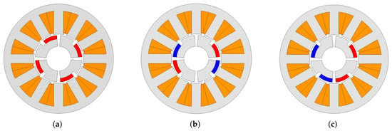
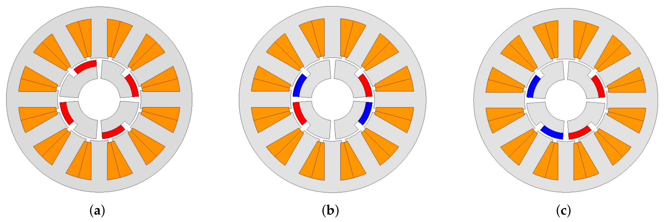
To overcome the limitations of the axial CP-PMSM, this paper proposes a consequent pole PMSM with a 2D structure that improves the magnetic field distribution through the pole arrangement. Figure 6 shows the 2D shapes of CP-PMSM comparison models for the pole arrangement. In the conventional CP-PMSM, only one polarity is formed by a permanent magnet, while the other polarity is formed by an iron pole, resulting in an imbalanced magnetic flux distribution, as illustrated in Figure 6a. In contrast, the proposed pole arrangements for the CP-PMSM rearrange the N, S, and iron poles in a circumferential direction, as illustrated in Figure 6b,c, thereby making the magnetic flux distribution more balanced over one mechanical period. In the axial CP-PMSM, which improves flux symmetry by stacking two CP-PMSM rotors in the axial direction, the proposed pole arrangement CP-PMSM achieves a similar effect by rearranging the pole structure within a single rotor in the circumferential direction. Therefore, the proposed structure can improve the air-gap magnetic field distribution without increasing the machine’s axial length. In addition, a segmented rotor structure is adopted to reduce flux leakage and shorten the magnetic flux path between the permanent magnet and the iron pole. This concentrates the main magnetic flux in the air-gap region and improves torque. Depending on the arrangement order of the permanent magnet poles and iron poles, the proposed pole arrangement CP-PMSM can be classified into symmetric and asymmetric structures.
Figure 6.
2D shapes of CP-PMSM comparison models: (a) conventional CP-PMSM, (b) symmetric CP-PMSM, (c) asymmetric CP-PMSM.
To evaluate the electromagnetic performance of only the rotor pole arrangement, the values of the design variables in Table 1 were set to be the same. The stator structure, pole and slot number, shape of permanent magnet, air-gap length, stack length, and analysis conditions were kept identical to ensure a fair comparison. Only the rotor pole arrangement was changed between the conventional CP-PMSM, the symmetric CP-PMSM, and the asymmetric CP-PMSM. The permanent magnet thickness and iron pole thickness were also fixed to maintain a magnetomotive force (MMF) and magnetic circuit conditions across all models. All electromagnetic performances were analyzed using 2D finite element analysis (2D-FEA) under identical operating conditions.
Table 1.
Design parameter specifications.
3.2. Symmetric CP-PMSM
Figure 6b shows the structure of the proposed symmetric pole arrangement CP-PMSM. The rotor is arranged in the order of N-pole, iron pole, iron pole, and S-pole, forming a symmetric structure over half of the mechanical period. Unlike conventional CP-PMSMs, which use only one magnetic polarity from a permanent magnet, the proposed structure includes both N-pole and S-pole permanent magnets within a single mechanical period, resulting in a more balanced magnetic flux distribution. Figure 7 shows the magnetic flux path by linearly representing a symmetric CP-PMSM. The main magnetic flux generated by the permanent magnet passes through the air gap to the stator and returns through the adjacent iron pole, forming the main magnetic circuit. Arrows indicate direction and the black line indicates magnet flux flow, as illustrated in Figure 7. However, some of the magnetic flux enters the permanent magnet rather than the adjacent iron pole, as illustrated by the pink line in Figure 7. Since this leakage flux degrades the electromagnetic performance of the proposed CP-PMSM, a segmented rotor structure is adopted to mitigate it, as illustrated in Figure 7. By separating the rotor core for each pole pair, the magnetic flux path between poles is shortened, thereby reducing the leakage flux and improving the main flux as well as the overall electromagnetic performance. For practical EPS motor applications, the mechanical robustness of the segmented rotor can be reinforced by applying non-magnetic bridges or retaining sleeves, while simultaneously maintaining the overall electromagnetic characteristics.
Figure 7.
Magnetic flux path of symmetric CP-PMSM.
3.3. Asymmetric CP-PMSM
Figure 6c shows the structure of the proposed asymmetric pole arrangement CP-PMSM. Unlike the symmetric CP-PMSM, the rotor poles are arranged in an asymmetric order over one mechanical period. This asymmetric pole arrangement changes the distribution of permanent magnet poles and iron poles, resulting in a different magnetic flux path compared with the symmetric CP-PMSM. Figure 8 shows the magnetic flux path by linearly representing the asymmetric CP-PMSM. The main magnetic flux generated by the permanent magnet still passes through the air gap to the stator and returns via the adjacent iron pole. Arrows indicate direction and black line indicate magnet flux flow, as illustrated in Figure 8. Unlike the symmetric CP-PMSM, which has two leakage flux paths, the asymmetric CP-PMSM has a single path, where the flux flows from the N-pole to the S-pole rather than through the iron pole, as illustrated by the pink line in Figure 8. Since this leakage flux similarly degrades electromagnetic performance, a segmented rotor structure is adopted.
Figure 8.
Magnetic flux path of asymmetric CP-PMSM.
3.4. Parametric Analysis of Iron Pole Arc Ratio
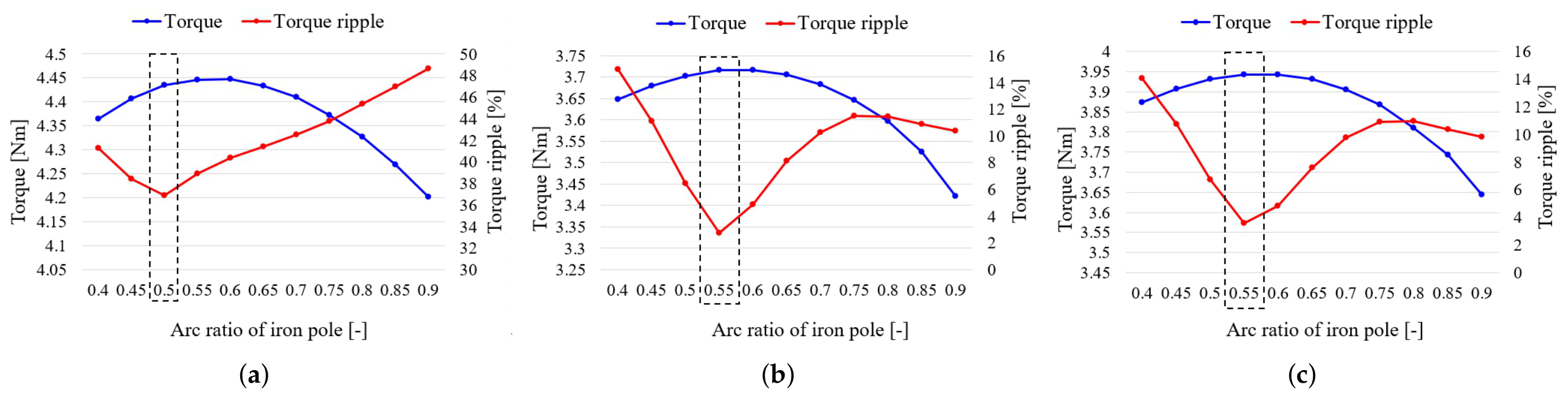
In this study, the stator structure and permanent magnet-related design variables are fixed to focus on the effect of rotor pole arrangement and iron pole arc ratio. Since CP-PMSMs are designed to reduce permanent magnet use, which is relatively expensive, the permanent magnet parameters are kept constant. Instead, the iron pole, which is composed of low-cost core material, is selected as the main design variable. As a result, the analysis is conducted by varying only the rotor-side parameters, and a trade-off between torque ripple and average torque is observed. Therefore, the purpose of this analysis is to investigate the influence of the iron pole arc ratio on the electromagnetic characteristics and to identify a favorable design point for subsequent model comparisons. The iron pole arc ratio is expressed by . Among the rotor-side design variables, is selected as the primary variable because it directly influences the magnetic flux distribution and torque ripple while maintaining a constant permanent magnet arc ratio. The is set to a common range of 0.4 to 0.9 across all models. The permanent magnet arc ratio is fixed at 0.8 to analyze only the effect of the iron pole. In addition, a segmented rotor structure is applied to all models to reduce leakage flux. Figure 9 shows the variation in average torque and torque ripple with for each model, and the dashed frame shows the selected.
Figure 9.
Torque and torque ripple according to the : (a) conventional CP-PMSM, (b) symmetric CP-PMSM, (c) asymmetric CP-PMSM.
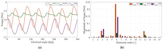
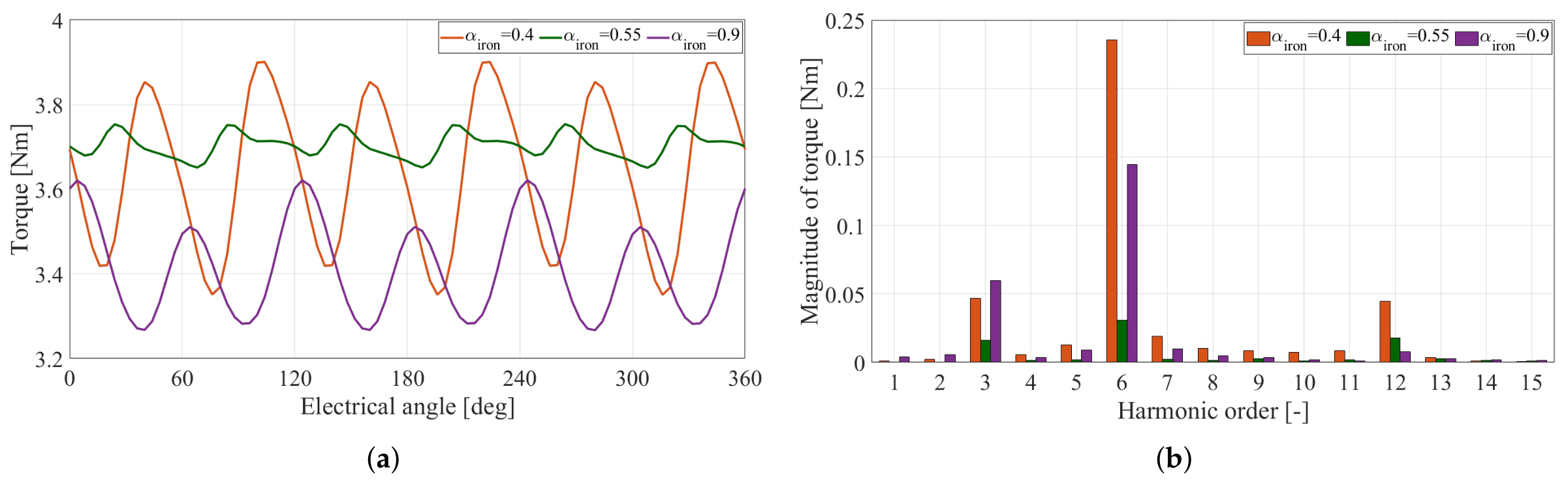
As varies, the torque and torque ripple change due to the corresponding variation in the magnetic flux path distribution. This variation in the flux path also affects the iron pole’s saturation, thereby modifying the magnetic flux distribution. Consequently, both the torque harmonic components and the torque ripple are influenced by the iron pole arc ratio. To analyze the characteristics with respect to , the symmetric CP-PMSM is selected as a representative case. Within the considered range of , the flux lines and torque harmonics are compared at three representative values: 0.4 (minimum), 0.55 (optimal), and 0.9 (maximum). Figure 10 shows the flux lines according to , illustrating the variation in flux distribution and flux paths. When , the flux distribution is mainly concentrated on the iron pole because of the high magnetic resistance in the leakage flux path. At , the flux distribution becomes more uniform. At , more flux tends to flow between adjacent iron poles because of the small magnetic resistance in the leakage flux path. Figure 11a shows the torque waveform according to . As shown in Figure 11b, dominant torque harmonic components, which are 3rd and 6th, are reduced at . It results in the minimum torque ripple while maintaining high average torque.
Figure 10.
Flux line of symmetric CP-PMSM according to ; (a) = 0.4, (b) = 0.55, (c) = 0.9.
Figure 11.
Torque of symmetric CP-PMSM according to : (a) waveform of torque and (b) fast Fourier transform of torque.
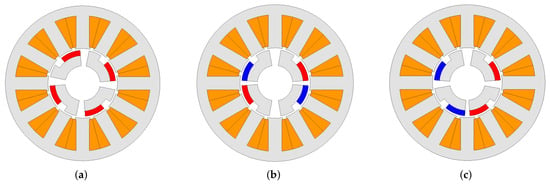
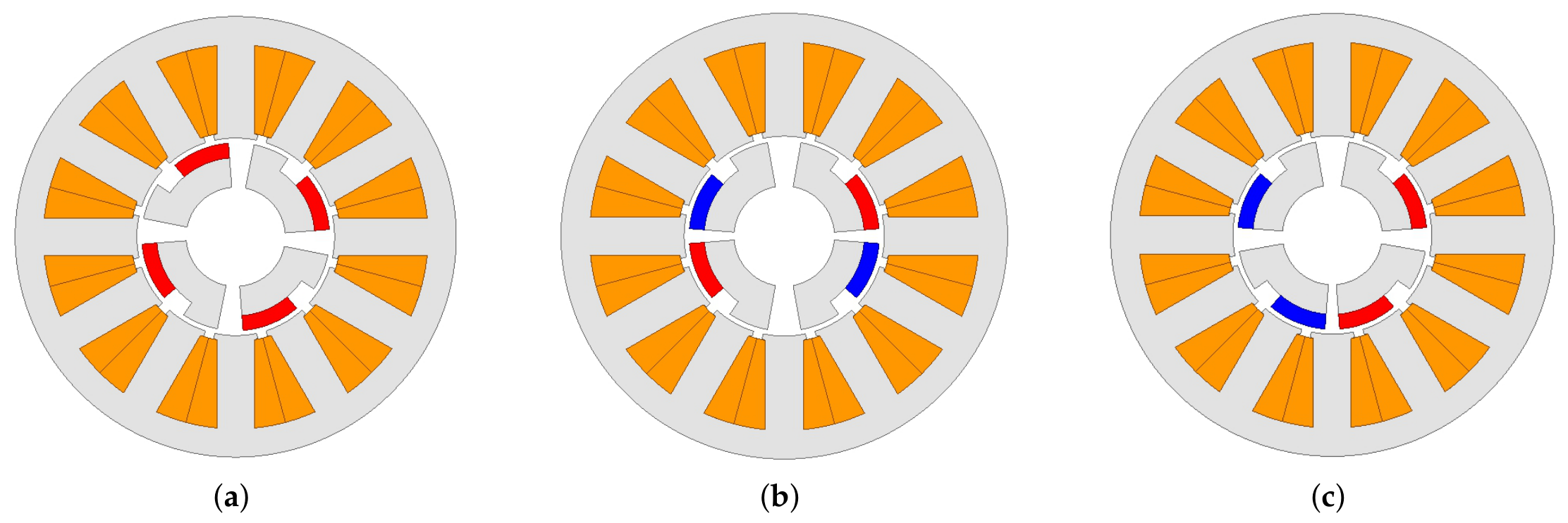
Similar tendencies are also observed in the conventional CP-PMSM and asymmetric CP-PMSM. The is selected for each model to obtain low torque ripple and high average torque, as illustrated in Figure 9. The selected values are 0.5 for the conventional CP-PMSM, 0.55 for the symmetric CP-PMSM, and 0.55 for the asymmetric CP-PMSM. Figure 12 shows each CP-PMSM model with the selected .
Figure 12.
CP-PMSMs with selected : (a) conventional CP-PMSM, (b) symmetric CP-PMSM, (c) asymmetric CP-PMSM.
4. Performance Comparison
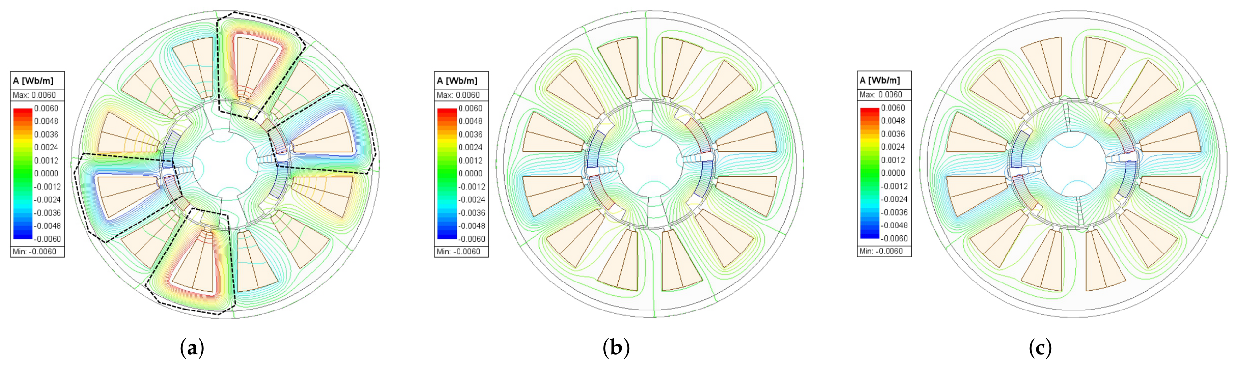
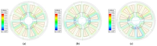
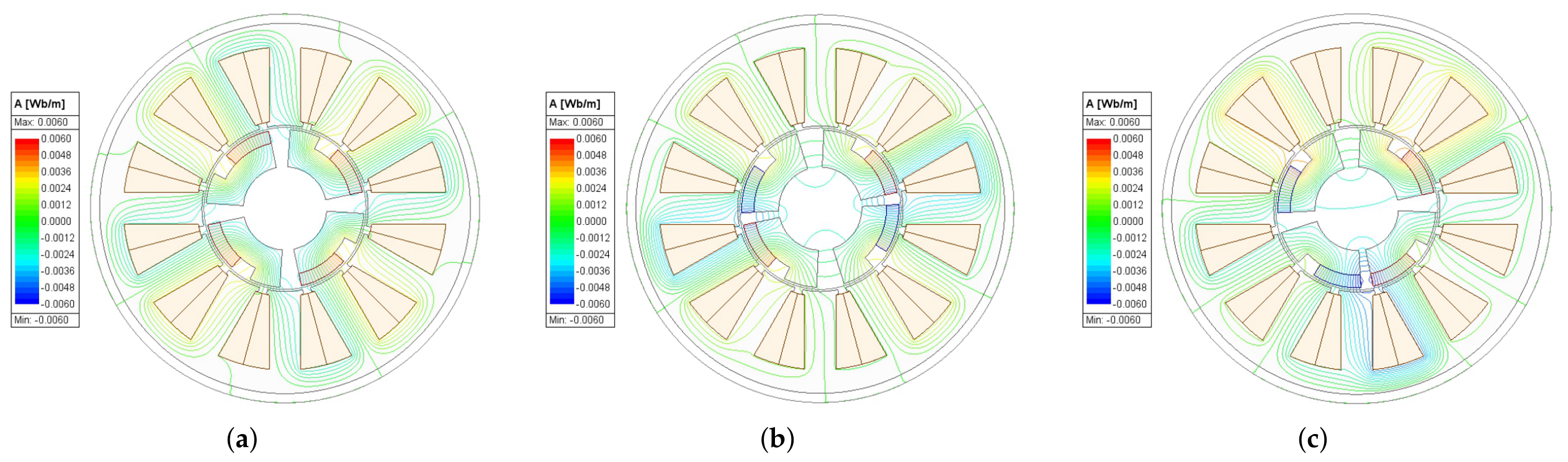
The electromagnetic characteristics of the conventional CP-PMSM, symmetric CP-PMSM, and asymmetric CP-PMSM with the selected are compared. Since the three models differ only in the arrangement of the permanent magnets and iron poles, the effect of the rotor pole arrangement on the electromagnetic performance is compared. The rotor pole arrangement influences the magnetic flux distribution, as illustrated in Figure 13. As shown in Figure 13, the conventional CP-PMSM has a flux path that is relatively concentrated around the iron pole. In contrast, the symmetric and asymmetric CP-PMSMs improve flux paths through their different pole arrangements, resulting in a more distributed flux pattern.
Figure 13.
Flux line of CP-PMSMs: (a) conventional CP-PMSM, (b) symmetric CP-PMSM, (c) asymmetric CP-PMSM.
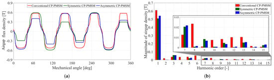
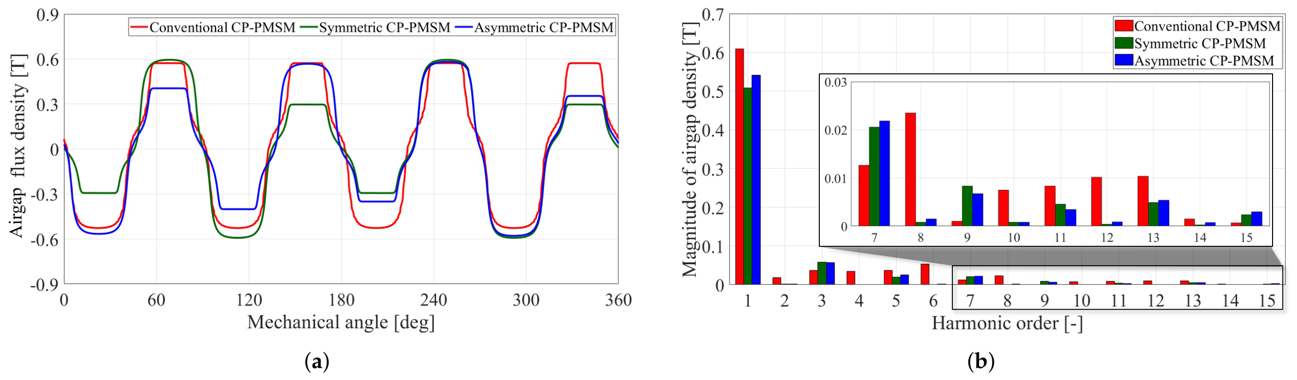
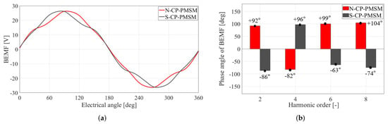
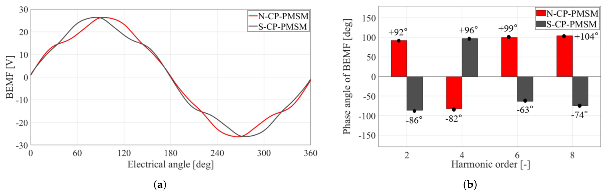
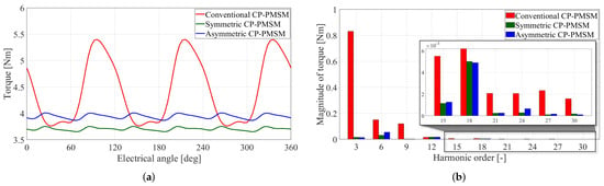
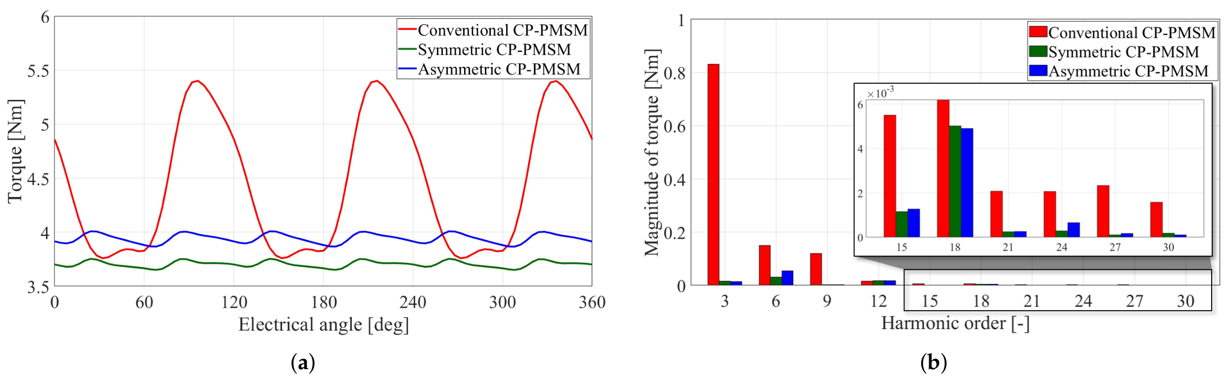
Figure 14a shows the air-gap flux density waveforms of the CP-PMSM models. Compared with the conventional CP-PMSM, the proposed symmetric and asymmetric CP-PMSMs show improved symmetry in the air-gap flux distribution due to the redistribution of the permanent magnets and iron poles. As shown in Figure 14b, the FFT results indicate that the proposed CP-PMSMs suppress several harmonic components, particularly the low-order harmonics generated by the asymmetric flux distribution around the iron poles. The improved air-gap flux symmetry modifies the air-gap MMF distribution and contributes to harmonic reduction. Figure 15 illustrates the harmonic cancellation characteristics of the N-CP-PMSM and S-CP-PMSM. As shown in Figure 15a, the N-CP-PMSM and S-CP-PMSM exhibit opposite waveform tendencies within one electrical period. In addition, the dominant harmonic components in Figure 15b show nearly opposite phase relationships between the N-CP-PMSM and S-CP-PMSM. Since the proposed CP-PMSMs are composed of combined N-CP-PMSM and S-CP-PMSM pole arrangements, partial cancellation of even-order harmonic components occurs in the proposed structures. Figure 16a shows the torque waveforms, where the peak-to-peak torque is reduced in the proposed CP-PMSM. In terms of average torque, the conventional CP-PMSM exhibits lower leakage flux than the proposed CP-PMSMs and therefore achieves the highest average torque. This tendency is consistent with Figure 16b, where the harmonic components, particularly the multiples of three, are reduced in the proposed CP-PMSM compared to the conventional CP-PMSM.
Figure 14.
Air-gap flux of CP-PMSMs: (a) waveform of air-gap flux and (b) fast Fourier transform of air-gap flux.
Figure 15.
Harmonic cancellation characteristics of the N-CP-PMSM and S-CP-PMSM: (a) BEMF waveform and (b) phase angle of dominant harmonic components.
Figure 16.
Torque of CP-PMSMs: (a) waveform of torque and (b) fast Fourier transform of torque.
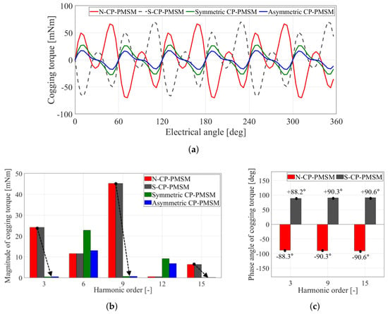
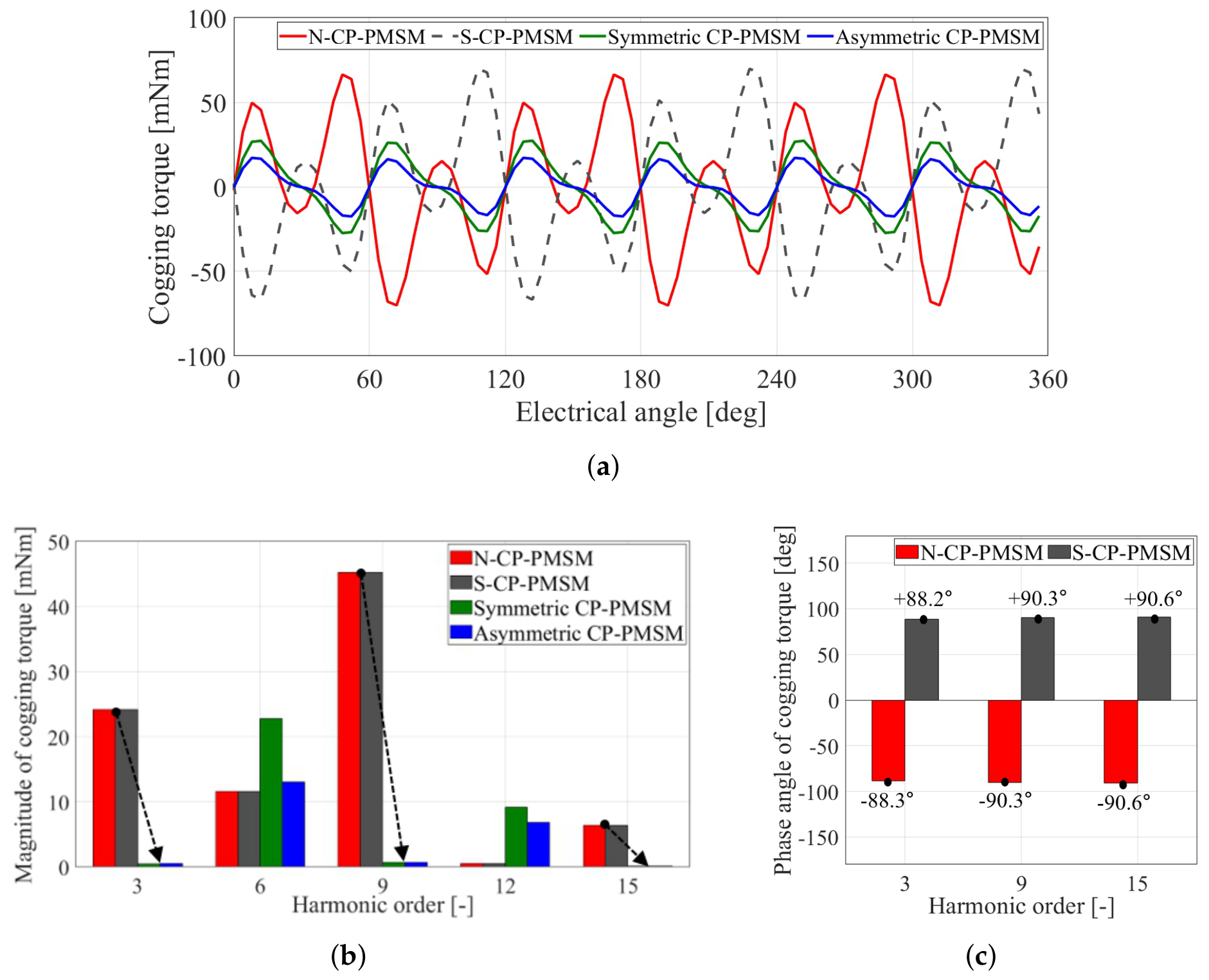
Although the proposed CP-PMSMs show reduced average torque compared with the conventional CP-PMSM, the results demonstrate a trade-off between torque capability and torque quality according to the rotor pole arrangement. In terms of average torque, the conventional CP-PMSM exhibits lower leakage magnetic flux compared with the proposed CP-PMSMs, resulting in the highest average torque. The cogging torque is also affected by the pole arrangement, as shown in Figure 17. Figure 17a shows the cogging torque waveforms of the CP-PMSM models. The proposed CP-PMSMs significantly reduce cogging torque compared with the conventional CP-PMSM. As shown in Figure 17b, the dominant cogging torque harmonic components are substantially reduced in the proposed CP-PMSMs. In addition, Figure 17c shows that the dominant harmonic components of the N-CP-PMSM and S-CP-PMSM exhibit nearly opposite phase relationships, which contributes to partial harmonic cancellation and reduced cogging torque in the proposed pole arrangements. The proposed CP-PMSM has a lower peak-to-peak cogging torque than the conventional CP-PMSM. To verify the validity of the 2D FEA results, additional 3D FEA was performed for the selected models. Although the absolute values of torque and torque ripple differ slightly due to axial leakage flux and end effects, the overall tendency remains unchanged. The proposed symmetric and asymmetric CP-PMSMs continue to exhibit significantly lower torque ripple than the conventional CP-PMSM. The comparison results are summarized in Table 2. To quantitatively compare the torque characteristics, the torque ripple and cogging torque are defined as follows:
To quantitatively compare the degree of waveform distortion, the total harmonic distortion (THD) of the BEMF was calculated as follows:
where is the amplitude of the fundamental component and is the amplitude of the n-th harmonic component. A lower THD indicates that the waveform is closer to a sinusoidal distribution. The THD of BEMF shows that the proposed CP-PMSM is more sinusoidal than the conventional CP-PMSM. Although the proposed CP-PMSMs show reduced average torque compared with the conventional CP-PMSM, the results demonstrate a trade-off between torque and torque ripple, depending on the rotor pole arrangement. In EPS applications, reducing torque pulsation and vibration is an important design consideration because these characteristics directly affect steering feel and driving comfort. Therefore, the proposed structures improve the overall torque characteristics despite the reduction in average torque. The torque ripple decreases from 36.91% in the conventional CP-PMSM to 2.76% and 3.59% in the symmetric and asymmetric CP-PMSMs, respectively. The cogging torque is also reduced in both models. In addition, the iron loss and magnet eddy-current loss were compared to evaluate whether the proposed pole arrangements adversely affect the loss characteristics. The iron loss decreases from 18.3 W in the conventional CP-PMSM to 16.19 W and 16.15 W in the symmetric and asymmetric CP-PMSMs, respectively. The magnet eddy-current loss also decreases from 1.02 W to 0.789 W and 0.798 W. These results indicate that the proposed pole arrangements reduce torque ripple without increasing the main electromagnetic loss components. As a result, the effectiveness of the proposed CP-PMSM is validated through performance comparison.
Figure 17.
Cogging torque of CP-PMSMs. (a) Waveform of cogging torque, (b) fast Fourier transform of cogging torque, (c) phase angle of cogging torque.
Table 2.
Performance of CP-PMSMs.
5. Conclusions
In this paper, symmetric and asymmetric rotor pole arrangements for CP-PMSMs are proposed to reduce torque ripple in EPS applications. The proposed structures modify the arrangement of permanent magnets and iron poles while maintaining a 2D configuration. The electromagnetic characteristics are analyzed using FEA under identical conditions. The results show that the proposed symmetric and asymmetric CP-PMSMs significantly reduce torque ripple from 36.91% to 2.76% and 3.59%, respectively, compared with the conventional CP-PMSM. In addition, the cogging torque is also reduced compared to the conventional CP-PMSM. Although a slight decrease in average torque is observed, the proposed CP-PMSMs also exhibit reduced iron loss and magnet eddy-current loss compared with the conventional CP-PMSM. Therefore, overall performance, including torque ripple, THD of BEMF, cogging torque, and loss characteristics, improves. The improvement is attributed to the modification of the rotor pole arrangement. Consequently, the proposed symmetric CP-PMSM and asymmetric CP-PMSM improve torque ripple and cogging torque without increasing axial length and requiring 3D analysis. Although this study is based on finite element analysis, practical implementation of the proposed CP-PMSMs is feasible for EPS applications. In experimental operation, differences between simulation and measured results may arise from manufacturing tolerances, assembly errors, inverter nonlinearity, and mechanical vibration. However, the torque ripple reduction tendency with the proposed pole arrangement is expected to remain valid under practical operating conditions.
Author Contributions
Conceptualization, C.J. and J.L.; methodology, C.J.; software, C.J.; validation, C.J. and J.L.; formal analysis, C.J.; investigation, C.J.; resources, C.J. and S.K.; data curation, C.J.; writing—original draft preparation, C.J.; writing—review and editing, C.J. and S.K.; visualization, C.J. and S.K.; supervision, J.L.; project administration, J.L.; funding acquisition, J.L. All authors have read and agreed to the published version of the manuscript.
Funding
This work was supported by the Korea Institute of Energy Technology Evaluation and Planning (KETEP) and the Ministry of Trade, Industry & Energy (MOTIE) of the Republic of Korea (No. RS-2024-00420625).
Institutional Review Board Statement
Not applicable.
Informed Consent Statement
Not applicable.
Data Availability Statement
The original contributions presented in this study are included in the article. Further inquiries can be directed to the corresponding author.
Conflicts of Interest
The authors declare no conflicts of interest.
References
- Zhu, Z.Q.; Howe, D. Electrical machines and drives for electric, Hybrid, and fuel cell vehicles. Proc. IEEE 2007, 95, 746–765. [Google Scholar] [CrossRef] [Scilit]
- Hwang, C.; Hung, S.; Liu, C.; Cheng, S. Optimal design of a high speed SPM motor for machine tool applications. IEEE Trans. Magn. 2014, 50, 4002304. [Google Scholar] [CrossRef] [Scilit]
- Qi, J.; Hua, W.; Zhang, H. Thermal analysis of modular-spoke-type permanent-magnet machines based on thermal network and FEA method. IEEE Trans. Magn. 2019, 55, 8104105. [Google Scholar] [CrossRef] [Scilit]
- Zhu, L.; Jiang, S.Z.; Zhu, Z.Q.; Chan, C.C. Analytical methods for minimizing cogging torque in permanent-magnet machines. IEEE Trans. Magn. 2009, 45, 2023–2031. [Google Scholar] [CrossRef] [Scilit]
- Abdel-Mageed, B.S.; Aljehaimi, A.M.; Pillay, P. Modeling and Remedies for Rare-Earth Permanent Magnet Demagnetization Effects in Hybrid Permanent Magnet Variable Flux Motors. IEEE Trans. Energy Convers. 2025, 40, 490–504. [Google Scholar] [CrossRef] [Scilit]
- Coey, J.M.D. Perspective and prospects for rare earth permanent magnets. Engineering 2020, 6, 119–131. [Google Scholar] [CrossRef] [Scilit]
- Xu, J.; Xu, W. The Design of Permanent Magnet Machine with Segmented Poles Based on Nanocomposite Magnets. IEEE Trans. Appl. Supercond. 2024, 34, 5208405. [Google Scholar] [CrossRef] [Scilit]
- Mohammadi Ajamloo, A.; Ghaheri, A.; Ibrahim, M.N.; Sergeant, P. A New Hybrid Permanent Magnet-Assisted Synchronous Reluctance Motor with Efficient Utilization of Rare-Earth Permanent Magnets. IEEE Trans. Energy Convers. 2025, 40, 1325–1338. [Google Scholar] [CrossRef] [Scilit]
- Lee, C. Design and Validation of SPMSM with Step-Skew Rotor for EPS System Using Cycloid Curve. Machines 2025, 13, 814. [Google Scholar] [CrossRef] [Scilit]
- Choi, D.; Kim, D.; Han, D.; Kim, W. Design of a slotless structure for minimizing cogging torque and torque ripple in a column type EPS motor for vehicles. IEEE Trans. Magn. 2024, 60, 8700305. [Google Scholar] [CrossRef] [Scilit]
- Lee, Y.; Gil, J.; Kim, W. Velocity control for sideband harmonics compensation in permanent magnet synchronous motors with low switching frequency inverter. IEEE Trans. Ind. Electron. 2021, 68, 3434–3444. [Google Scholar] [CrossRef] [Scilit]
- Jo, S.-J.; Bada, S.-W.; Hwang, K.-Y. Optimization Design of Novel Consequent Pole Motor for Electric Power Steering System. Machines 2024, 12, 893. [Google Scholar] [CrossRef] [Scilit]
- Li, F.; Wang, K.; Li, J.; Sun, H.Y. Electromagnetic Performance Analysis of Consequent-Pole PM Machine with Asymmetric Magnetic Pole. IEEE Trans. Magn. 2019, 55, 8103205. [Google Scholar] [CrossRef] [Scilit]
- Qi, J.; Zhu, Z.Q.; Yan, L.; Jewell, G.W.; Gan, C.W.; Ren, Y.; Brockway, S.; Hilton, C. Suppression of Torque Ripple for Consequent Pole PM Machine by Asymmetric Pole Shaping Method. IEEE Trans. Ind. Appl. 2022, 58, 3545–3557. [Google Scholar] [CrossRef] [Scilit]
- Qi, J.; Zhu, Z.Q.; Yan, L.; Jewell, G.W.; Gan, C.W.; Ren, Y.; Brockway, S.; Hilton, C. Effect of Pole Shaping on Torque Characteristics of Consequent Pole PM Machines. In Proceedings of the 2021 IEEE International Electric Machines & Drives Conference (IEMDC), Hartford, CT, USA, 17–20 May 2021; pp. 1–8. [Google Scholar]
- Qi, J.; Zhu, Z.Q.; Yan, L.; Jewell, G.W.; Gan, C.; Ren, Y.; Brockway, S.; Hilton, C. Analytical Analysis of Cogging Torque in Permanent Magnet Machines with Unequal North and South Poles, with Particular Reference to Consequent Pole Machines. IEEE Trans. Energy Convers. 2023, 38, 1361–1375. [Google Scholar] [CrossRef] [Scilit]
- Guo, L.; Yu, H.; Wang, H. Design and Optimization of External Rotor Consequent Pole Permanent Magnet Motor with Low Iron Loss and Low Torque Ripple. World Electr. Veh. J. 2024, 15, 232. [Google Scholar] [CrossRef] [Scilit]
- Li, H.; Yang, H.; Lin, H.; Zhao, Z. Comparative Study of Field Modulation Effects in Consequent-Pole PM Machines with Different Stator Slot Configurations. IEEE Trans. Magn. 2023, 59, 8103706. [Google Scholar] [CrossRef] [Scilit]
- Zheng, Y.; Zhu, Z.Q.; Liang, D.; Zhou, Y.; Liu, H.; Chen, L. Analysis and Reduction of Unipolar End Leakage Flux in Consequent-pole Vernier and Fractional Slot PM Machines. In Proceedings of the 2023 IEEE International Electric Machines & Drives Conference (IEMDC), San Francisco, CA, USA, 15–18 May 2023; pp. 1–7. [Google Scholar]
- Wang, L.; Saeed, M.S.; Fu, Z.; Liu, J.; Wu, X.; Wang, Q. Magnetic Circuit Analysis and Design Optimized for Cost-Effectiveness of Surface-Inserted Rare Earth Consequent-Pole Permanent Magnet Machines. Machines 2025, 13, 873. [Google Scholar] [CrossRef] [Scilit]
- Jo, C.; Yun, I.; Hong, H.; Lee, J.; Kim, H. Asymmetric Design of Consequent Pole to Reduce Torque Ripple. IEEE Trans. Magn. 2024, 60, 8204905. [Google Scholar] [CrossRef] [Scilit]





Disclaimer/Publisher’s Note: The statements, opinions and data contained in all publications are solely those of the individual author(s) and contributor(s) and not of MDPI and/or the editor(s). MDPI and/or the editor(s) disclaim responsibility for any injury to people or property resulting from any ideas, methods, instructions or products referred to in the content. |
© 2026 by the authors. Licensee MDPI, Basel, Switzerland. This article is an open access article distributed under the terms and conditions of the Creative Commons Attribution (CC BY) license.