


Abstract
Most existing analytical models for gear skiving define the cutting edge indirectly through hypothetical generating gears. This abstraction introduces an inherent geometric inconsistency between the theoretical cutting edge and the true conical rake surface of the cutter, limiting prediction accuracy and hindering measurement-driven compensation. To address this limitation, this study proposes a unified analytical and measurement-driven framework for cylindrical gear skiving that eliminates the generating-gear assumption entirely. A direct surface-based meshing formulation is developed by enforcing positional coincidence and tangential compatibility directly on the cutter’s conical rake surface, ensuring strict geometric consistency with the physical cutting mechanism. To incorporate real cutter deviations, a tension-controlled spline reconstruction method is introduced to recover smooth and curvature-stable cutting edge curves from noisy three-dimensional measurement data, overcoming the oscillation and instability commonly associated with high-order polynomial fitting. By integrating direct surface-based meshing, spline-regularized reconstruction, and CNC-oriented kinematics within a single formulation, this work establishes a complete digital chain for precision skiving cutter modeling, simulation, and compensation, providing a practical foundation for advanced tool design and manufacturing optimization.
1. Introduction
Gear skiving has re-emerged as a key technology for high-precision machining of cylindrical gears, driven by advances in multi-axis CNC synchronization, cutting-tool manufacturing, and high-resolution metrology. Since the early conceptual work of Adams [1], extensive research has addressed skiving tool geometry, kinematic coupling, meshing theory, and tooth-profile error prediction. Practical tool-design methodologies and machine implementations have been reported by Seibicke and Müller [2], Stadtfeld [3], and Tsai and co-workers [4,5,6,7], while related developments include error-free conical and cylindrical skiving tools proposed by Shih and Li [8,9] and correction strategies targeting uniform grinding allowance and profile accuracy [10].
Parallel research has focused on understanding skiving kinematics, cutting mechanics, and process sensitivity. Prior studies investigated chip formation and cutting mechanisms [11], theoretical tooth-profile errors [12], chip-load and cutting-force prediction [13], penetration-based numerical simulation of the skiving process [14,15], and the influence of tool eccentricity on surface roughness [16]. Collectively, these works highlight the strong sensitivity of skiving accuracy to geometric consistency and synchronized multi-axis motion.
Despite these advances, most existing analytical models still define the cutter edge indirectly by extracting sectional profiles from hypothetical generating gears. This construction implicitly assumes geometric equivalence between the generating-gear tooth section—typically defined on a plane or a cylindrical surface—and the actual cutting edge, which lies on a non-developable conical rake surface. As a result, a systematic geometric mismatch persists between theoretical predictions and the true cutting mechanism. This limitation becomes increasingly critical in modern manufacturing environments, where cutter geometry is evaluated using high-resolution three-dimensional measurement and corrected through CNC-based compensation.
Measurement-driven reconstruction of cutter edges has therefore attracted growing attention. However, conventional high-order polynomial fitting methods commonly used in industrial tool inspection often suffer from oscillation, curvature distortion, and sensitivity to noise or uneven point distribution. In this context, tension-controlled spline interpolation provides a more stable alternative for reconstructing cutter edge curves from measured data [17].
Nevertheless, existing studies typically treat cutter edge definition, meshing simulation, and CNC-axis implementation as largely independent problems. Analytical meshing formulations are commonly derived from generating-gear abstractions, while measurement-based reconstruction and machine-axis compensation are developed in parallel without a unified geometric foundation. Consequently, no existing framework simultaneously integrates direct surface-based meshing on the conical rake surface, measurement-driven reconstruction of the cutter edge, and CNC-consistent kinematics within a single analytical formulation. This disconnect limits the predictive fidelity of skiving simulations and restricts their practical use for systematic machine-parameter refinement.
To address these limitations, the present study proposes a unified analytical and measurement-driven framework for cylindrical gear skiving. The framework is built upon three key contributions:
- (i)
- A direct surface-based meshing formulation in which positional coincidence and tangential compatibility are enforced directly on the cutter’s conical rake surface, eliminating the need for a hypothetical generating gear;
- (ii)
- A tension-spline-based reconstruction method that robustly recovers smooth and curvature-stable cutting edge geometry from measured three-dimensional data;
- (iii)
- A CNC-consistent six-axis kinematic representation that explicitly maps analytical parameters—such as offset angle, crossing angle, synchronized rotations, and axial feed—to the physical axis configuration of modern skiving machines.
Together, these elements form a complete digital chain linking measurement, reconstruction, meshing analysis, and machine-parameter compensation.
2. Universal Mathematical Model of Cylindrical Gear Skiving
This section establishes a unified kinematic formulation for cylindrical gear skiving, which serves as the analytical foundation for the direct surface-based meshing model developed in Section 3. The objective is to describe the relative motion between the cutter and the workpiece in a form that is both mathematically rigorous and directly compatible with the axis architecture of modern six-axis CNC skiving machines.
2.1. Skiving Kinematics and Axis Configuration
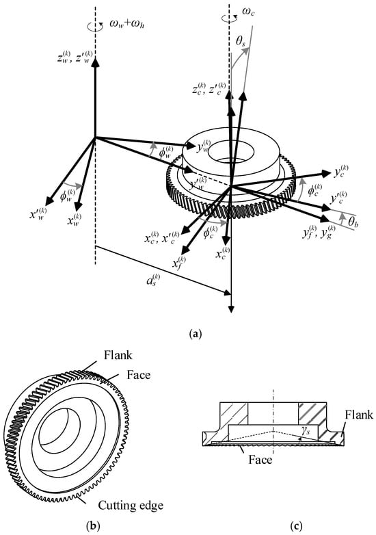
Cylindrical gear skiving is characterized by a skew-axis engagement between the cutter and the workpiece, as illustrated in Figure 1a and originally formulated in early analytical studies [15], with subsequent refinements for numerical simulation and machine implementation. In this process, the cutter axis is intentionally inclined relative to the workpiece axis in order to generate the relative sliding motion required for chip formation.
Figure 1.
Kinematical configuration [15] of cylindrical skiving tool. (a) Relative configuration between the cutter and the workpiece. (b) Cylindrical skiving cutter. (c) Conical rake surface of the skiving cutter.
As shown in Figure 1b,c, the cutter body itself is cylindrical, whereas its rake surface is ground as a truncated cone. This conical rake geometry ensures that the active cutting edge remains geometrically consistent under repeated resharpening, while simultaneously providing the effective rake and clearance angles required for stable cutting.
The relative orientation between the cutter and the workpiece is commonly described using two tilt angles. The side-tilt angle θs defines the inclination of the cutter axis within the X–Z plane, while the back-tilt angle θb specifies the inclination within the Y–Z plane. Together, these angles determine the spatial skew between the two rotational axes and therefore govern the local cutting kinematics.
During the skiving process, the cutter and the workpiece rotate about their respective axes with instantaneous rotational angles and . The center distance defines the spatial separation between the two axes at a given instant. These parameters fully describe the instantaneous relative configuration between the cutter coordinate system and the workpiece coordinate system , as illustrated in Figure 1a.
The relative motion between the two coordinate systems can be expressed compactly using a rigid-body transformation that combines rotation and translation:
where the rotation matrix
captures the combined effects of cutter rotation, workpiece rotation, and cutter inclination, and the translation vector
represents the center-distance offset expressed in the rotating workpiece frame. This formulation provides a concise and physically interpretable representation of the cutter-workpiece kinematics and forms the basis for the coordinate transformations used later in the meshing analysis.
The rotational speeds of the cutter and workpiece, denoted by ωc and ωw, must satisfy a synchronized relationship determined by the tooth numbers of the cutter and the workpiece:
where Nc and Nw are the numbers of teeth of the cutter and the workpiece, respectively; βw is the helix angle of the workpiece; and mtw is the transverse module of the workpiece.
For internal gear skiving, the fundamental conjugate-motion condition requires that the angular velocities be proportional to the inverse ratio of tooth numbers. For external gears, the rotation direction of the workpiece is reversed, corresponding to the opposite sign in Equation (4). This synchronization ensures that the cutting edge engages successive tooth flanks in a conjugate manner.
For helical gears, the kinematic relationship is further modified by an additional rotational component associated with the axial feed motion. This coupling accounts for the fact that axial translation of the workpiece induces an effective rotational motion along the helical tooth path. As a result, the instantaneous cutting point follows the prescribed helical contact line rather than a purely transverse trajectory.
The conical rake surface of the cutter, characterized by the cone angle γc, plays a central role in determining the effective rake and clearance angles during cutting. These effective angles depend not only on the cutter geometry itself, but also on the synchronized rotational motion, the axis inclination, and the axial feed. Accurate modeling of skiving therefore requires that tool geometry, kinematics, and machine settings be treated within a single, coherent framework.
2.2. CNC-Consistent Six-Axis Kinematic Representation
Modern power-skiving machines employ multi-axis architectures that integrate translational and rotational motions to realize the required skew-axis engagement. To ensure direct applicability of the analytical formulation to real manufacturing systems, the generalized skiving kinematics must be expressed in a form that aligns with the physical axis configuration of a six-axis CNC platform.
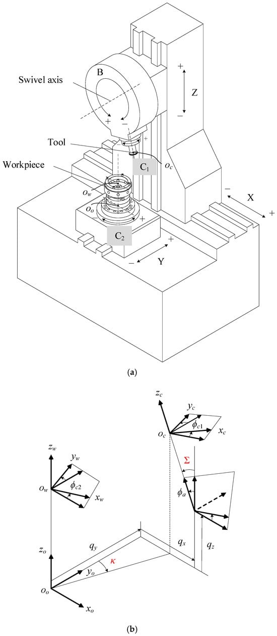
As shown in Figure 2, a representative machine configuration consists of three translational axes (X, Y, Z) and three rotational axes (C1, C2, B). The cutter is mounted on the C1-axis, while the workpiece is mounted on the C2-axis. The B-axis provides the swivel motion that establishes the crossing angle Σ between the cutter and workpiece axes. Together, these axes enable full control over the relative position and orientation of the cutter and workpiece coordinate systems Sc and Sw.
Figure 2.
Configuration of the six-axis gear cutting machine. (a) Overall machine-axis configuration. (b) Coordinate system of the six-axis skiving machine.
Within this configuration, the crossing angle Σ corresponds directly to the rotation of the B-axis. The offset angle κ is realized through a rotation about the global Z-axis prior to the B-axis swivel. The center distance as is implemented through coordinated translations along the X and Y axes, while the axial feed qf is applied along the Z-axis in alignment with the workpiece axis.
This mapping ensures that every analytical parameter appearing in the kinematic formulation has a direct physical counterpart on the machine tool. As a result, meshing simulations can be executed using actual machine positions, and corrective strategies derived from analytical sensitivity analysis can be implemented without additional coordinate reinterpretation.
2.3. Modified Coordinate Systems and Machine Parameters
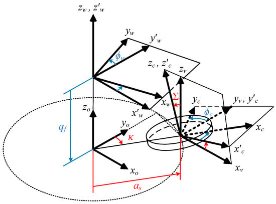
To establish a compact and CNC-compatible description of the skiving process, the spatial relationship between the cutter and the workpiece is reformulated using a set of machine-setting parameters that map naturally to the six-axis configuration. Instead of expressing the cutter inclination directly in terms of the side-tilt and back-tilt angles (θs and θb), the modified coordinate framework shown in Figure 3 employs the crossing angle Σ, the offset angle κ, and the center distance as as primary parameters.
Figure 3.
Modified coordinate systems for cylindrical tool skiving.
The offset angle κ represents a rotation of the cutter axis about the machine Z-axis, while the crossing angle Σ defines the angular skew between the cutter and workpiece axes within the transverse plane. Together with the center distance as, these parameters uniquely determine the relative placement of the cutter coordinate system Sc and the workpiece coordinate system Sw.
The rotational states of the cutter and workpiece are described by the rotation angles ϕc and ϕw about their respective axes, while the axial feed displacement qf specifies translation along the workpiece axis. These motion variables, combined with the machine-setting parameters, define the complete relative kinematics required for chip generation:
Equation (6) is formulated for the internal gear configuration. For external gears, the rotation of the workpiece is reversed, and the term −ϕw should be replaced by +ϕw. The sign of the offset angle κ depends on the machining configuration: for internal gears, κ follows the sign of the crossing angle Σ, whereas for external gears the sign relationship is reversed.
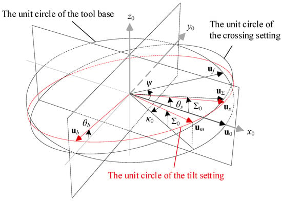
To geometrically represent the angular parameters within the machine-setting coordinate system So, a unit-circle formulation is adopted, as illustrated in Figure 4. The initial unit vector u0 is defined on the xo-yo plane of So. This vector is first rotated about the yo-axis to establish the prescribed crossing angle Σ0, resulting in the vector uΣ. Subsequently, uΣ is rotated about the zo-axis κ0, yielding the intermediate vector um.
Figure 4.
The geometry of unit vectors of the rotation transformation.
Within this formulation, the side-tilt angle θs is enforced through constraints in the xo-zo plane, while the back-tilt angle θb is enforced through constraints in the yo-zo plane. Solving the resulting constraint equations yields the closed-form relationships between the conventional tilt angles and the machine-setting parameters, as summarized in Equations (8)–(13).
Here, κ0 and Σ0 denote the initial machine settings defining the nominal configuration. The generalized parameter κ and Σ are subsequently introduced as adjustable variables, enabling sensitivity analysis and compensation in Section 4.
The resulting coordinate system provides
- (1)
- a compact representation of the spatial relationship between the cutter and the workpiece,
- (2)
- direct compatibility with six-axis CNC platforms, and
- (3)
- a mathematically robust foundation for the direct surface-based meshing formulation introduced in Section 3.
3. Direct Surface-Based Meshing Formulation for Cutting Edge Derivation
This section presents a direct surface-based meshing formulation for deriving the skiving cutter edge from the true physical interaction between the cutter’s conical rake surface and the workpiece tooth surface. In contrast to conventional approaches that define the cutting edge indirectly through hypothetical generating gears, the present formulation enforces the meshing conditions directly on the physical rake surface. The resulting cutting edge curve therefore emerges naturally from the actual cutter–workpiece kinematics and geometry.
The formulation proceeds as follows. First, the geometric representation of the conical rake surface is introduced. Next, the coupled rotational and axial-feed kinematics of the skiving process are incorporated. The workpiece tooth surface is then mapped into the cutter coordinate system using the CNC-consistent transformations developed in Section 2. Finally, the positional coincidence and tangential compatibility conditions are enforced simultaneously to identify physically admissible cutting edge points.
3.1. Geometric Definition of the Conical Rake Surface
The active cutting geometry of a skiving tool is defined by the instantaneous intersection between the cutter’s conical rake surface and the workpiece tooth surface under synchronized relative motion. Unlike generating-gear-based formulations, which implicitly assume that the cutting edge lies on an auxiliary planar or cylindrical surface, the present approach takes the conical rake surface itself as the fundamental meshing boundary.
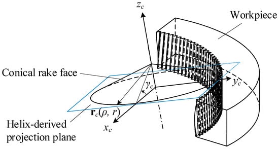
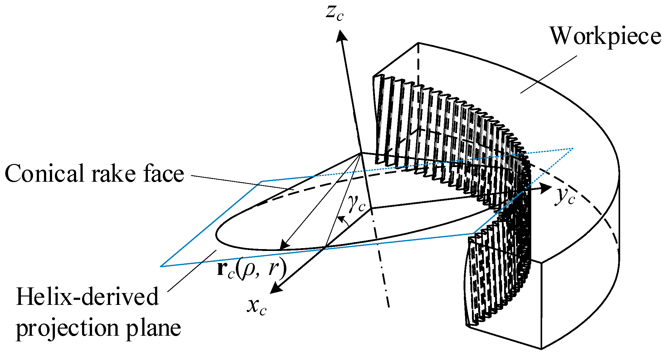
Let the cutter coordinate system be denoted by Sc, with its zc-axis aligned with the cutter axis. As illustrated in Figure 5, the conical rake surface is modeled as a truncated cone characterized by the cone angle γc. A generic point on the rake surface is expressed parametrically as
where r is the radial parameter measured along the generator lines of the cone, ρ is the circumferential parameter around the cone axis, and r ≤ Rc defines the active extent of the rake surface. This explicit parameterization provides a smooth and well-defined domain on which the meshing constraints can be imposed directly.
Figure 5.
Geometric definition of the cutter rake surface and coordinate parameters.
3.2. Coupled Rotational and Axial-Feed Kinematics
During skiving, the cutter and the workpiece undergo a coordinated combination of rotation and axial translation. These motions jointly determine the instantaneous relative position of the two surfaces and therefore govern the spatial trajectory of the cutting edge.
Let ϕc and ϕw denote the rotational angles of the cutter and workpiece, respectively. The axial feed displacement along the workpiece axis is expressed as
where fw is the axial feed rate of the workpiece, ωc and ωw are the angular velocities of the cutter and workpiece, and k is the index of repeated engagements on the same tooth flank. The first term represents the continuous feed accumulated during cutter rotation, while the second term accounts for the axial shift between successive tooth engagements.
The rotational motions of the cutter and workpiece satisfy the synchronized relationship given in Equation (4). For helical gears, this relationship includes an additional rotational contribution associated with the axial feed, ensuring that the instantaneous cutting point follows the prescribed helical contact path of the workpiece tooth surface.
3.3. Mapping of the Workpiece Tooth Surface into the Cutter Frame
To evaluate the meshing conditions directly on the conical rake surface, the workpiece tooth surface must be expressed in the cutter coordinate system. This mapping is essential because the cutting edge is defined on the cutter itself, whereas the workpiece tooth surface is naturally parameterized in its own rotating and translating frame. A consistent description of the contact geometry therefore requires that both surfaces be represented in a common coordinate system.
Using the CNC-consistent transformation framework established in Section 2, a point on the workpiece tooth surface parameterized by the surface coordinates (u, v) is mapped into the cutter coordinate system as
Here pw(u, v) denotes the parametric position vector of the workpiece tooth surface expressed in the workpiece coordinate system Sw, while pc represents the same physical point expressed in the cutter coordinate system Sc. The transformation matrices Mcw and mcw, defined in Equations (6) and (7), account explicitly for the synchronized rotations of the cutter and workpiece, the crossing angle, the offset angle, and the axial feed displacement.
Importantly, the motion variables ϕw and qf are not independent. The rotational angle ϕw is constrained by the conjugate-motion relationship in Equation (4), while the axial feed displacement qf evolves continuously with cutter rotation and tooth indexing, as described in Section 3.2. As a result, the mapped workpiece surface pc represents the instantaneous spatial configuration of the workpiece tooth surface relative to the cutter at any given cutter rotation angle ϕc.
This mapping establishes the kinematic bridge between the workpiece surface geometry and the cutter geometry. Once expressed in the cutter coordinate system, the workpiece tooth surface can be directly intersected with the conical rake surface, enabling the cutting edge to be derived without introducing any hypothetical generating gear or auxiliary surface.
3.4. Positional Coincidence Condition
A necessary condition for contact between the cutter and the workpiece is that corresponding points on the two surfaces coincide in three-dimensional space. Let (r, ρ) denote a point on the conical rake surface and (u, v, ϕc, qf) denote a point on the workpiece tooth surface. The positional coincidence condition is expressed as
This vector equation represents the geometric intersection between the rake surface and the transformed workpiece tooth surface at a given instant of the skiving process. For a prescribed profile parameter u, the condition defines a locus of intersection points on the conical rake surface as the cutter rotates and the workpiece advances axially.
However, positional coincidence alone is not sufficient to identify physically admissible cutting edge points. Pure geometric intersection does not guarantee that the relative motion at the contact point is compatible with cutting. In particular, intersection points may exist at which the instantaneous relative velocity penetrates the rake surface or causes sliding in a direction inconsistent with chip formation.
From a physical standpoint, a valid cutting edge must satisfy two simultaneous requirements:
- (1)
- The cutter and workpiece surfaces must coincide at the contact point;
- (2)
- The instantaneous relative velocity must lie within the tangent plane of the rake surface.
The first requirement is enforced by the positional coincidence condition, while the second requirement is enforced through the tangential compatibility condition introduced in Section 3.5. Together, these two constraints distinguish true cutting contact from mere geometric intersection.
Therefore, the positional coincidence condition serves as a necessary but not sufficient criterion. Only by coupling it with the tangential compatibility condition can the true cutting edge curve be uniquely identified on the conical rake surface.
3.5. Tangential Compatibility and the Equation of Meshing
Among all intersection points satisfying the positional coincidence condition, only those points for which the instantaneous relative motion is compatible with chip formation correspond to physically admissible cutting contact. This requirement constitutes the tangential compatibility condition, which serves as the equation of meshing in the present formulation.
From a geometric standpoint, the workpiece tooth surface and the conical rake surface intersect along a curve defined implicitly by the positional coincidence condition. However, from a kinematic standpoint, material removal can occur only if the instantaneous relative velocity at the contact point lies within the tangent plane of the rake surface. Any velocity component normal to the rake surface would imply penetration of the tool into the rake face, which is physically impossible and inconsistent with cutting mechanics.
The normal vector of the workpiece tooth surface expressed in the cutter coordinate system is obtained as
while the normal vector of the conical rake surface is given by
At their intersection, the local intersection direction between the two surfaces is defined by
which lies in both tangent planes and represents the instantaneous direction along which the two surfaces intersect.
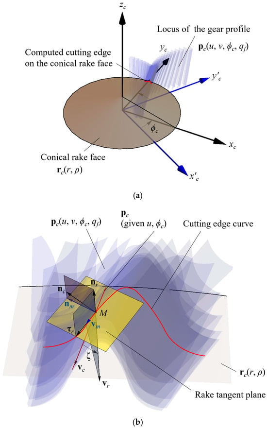
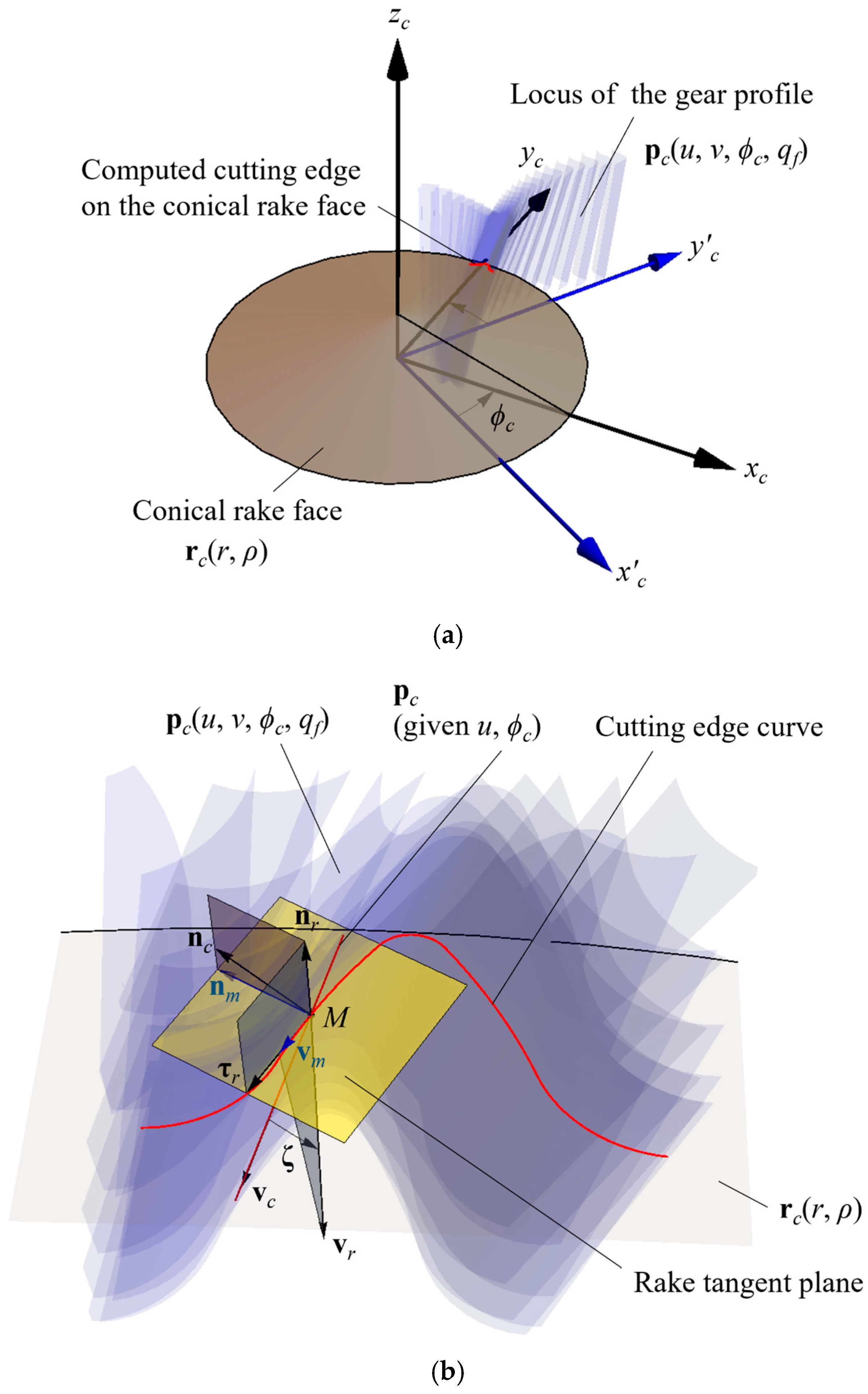
To enforce a physically meaningful cutting condition, an admissible normal vector nm is constructed such that it lies in the tangent plane of the rake surface and is orthogonal to the intersection direction τr. This construction ensures that nm represents the effective normal of the rake tangent plane at the contact point:
The instantaneous relative velocity vc, induced primarily by cutter rotation and coupled axial-feed motion, is then projected onto the rake tangent plane to obtain
Since the rake-tangent-plane normal defined in Equation (21) is obtained through a rotation-based construction, the relative velocity vector must be treated consistently. The angle between the two surface normals is therefore introduced as
and the relative velocity is re-oriented with respect to the intersection direction by the corresponding rotational transformation
The component of this re-oriented velocity lying within the tangent plane of the conical rake surface is then extracted through projection
The tangential compatibility condition, or equation of meshing, is finally expressed by
Physically, this condition enforces that the relative velocity has no component along the admissible normal of the rake tangent plane. In other words, the cutter and workpiece surfaces slide relative to each other within the rake tangent plane, rather than penetrating it. This distinguishes true cutting contact from mere geometric intersection or rubbing contact.
Solving the positional coincidence and tangential compatibility conditions simultaneously yields a continuous spatial curve on the conical rake surface. This curve represents the true cutting edge, defined entirely by the physical cutter geometry and the actual skiving kinematics, without reference to any hypothetical generating gear.
Figure 6 illustrates the geometric and kinematic framework associated with this procedure. Figure 6a shows the transformed workpiece surface sweeping through the cutter coordinate system under the coupled rotational and feed motion. Figure 6b depicts the construction of the cutting edge via the rake-tangent-plane compatibility condition, including the geometric intersection, the rake tangent plane, and the associated velocity projection.
Figure 6.
Computed cutting edge on the conical rake face obtained from the equation of meshing. (a) Instantaneous relative configuration of the workpiece surface and rake face. (b) Construction of the cutting edge via the rake-constrained meshing condition.
3.6. Helix-Derived Projection for Cutter Profile Construction
The cutting edge curve obtained from the direct meshing formulation is a three-dimensional spatial curve embedded on the conical rake surface. While this spatial representation is essential for accurate meshing analysis, it cannot be used directly for cutter manufacturing or inspection, which are typically performed in a planar coordinate system.
In practical skiving cutter production, the cutting edge is ground and inspected along a plane associated with the cutter’s helical motion. To bridge this gap between spatial meshing geometry and manufacturable tool profiles, a helix-derived projection is introduced.
Let the spatial cutting edge curve in the cutter coordinate system Sc be denoted by pc(u), where u represents the profile-direction parameter. The projected point in the cutter’s helical coordinate system Ss is given by:
where Msc is the transformation matrix defined as
Here, rc denotes the cutter pitch radius, βc is the cutter helix angle, and v represents the lead-direction parameter along the helical motion of the cutter.
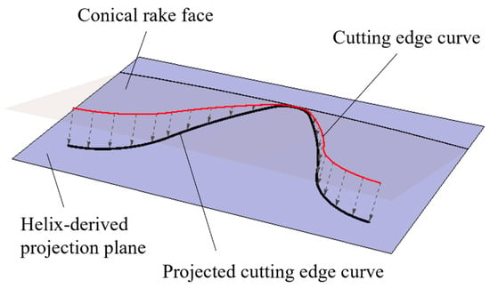
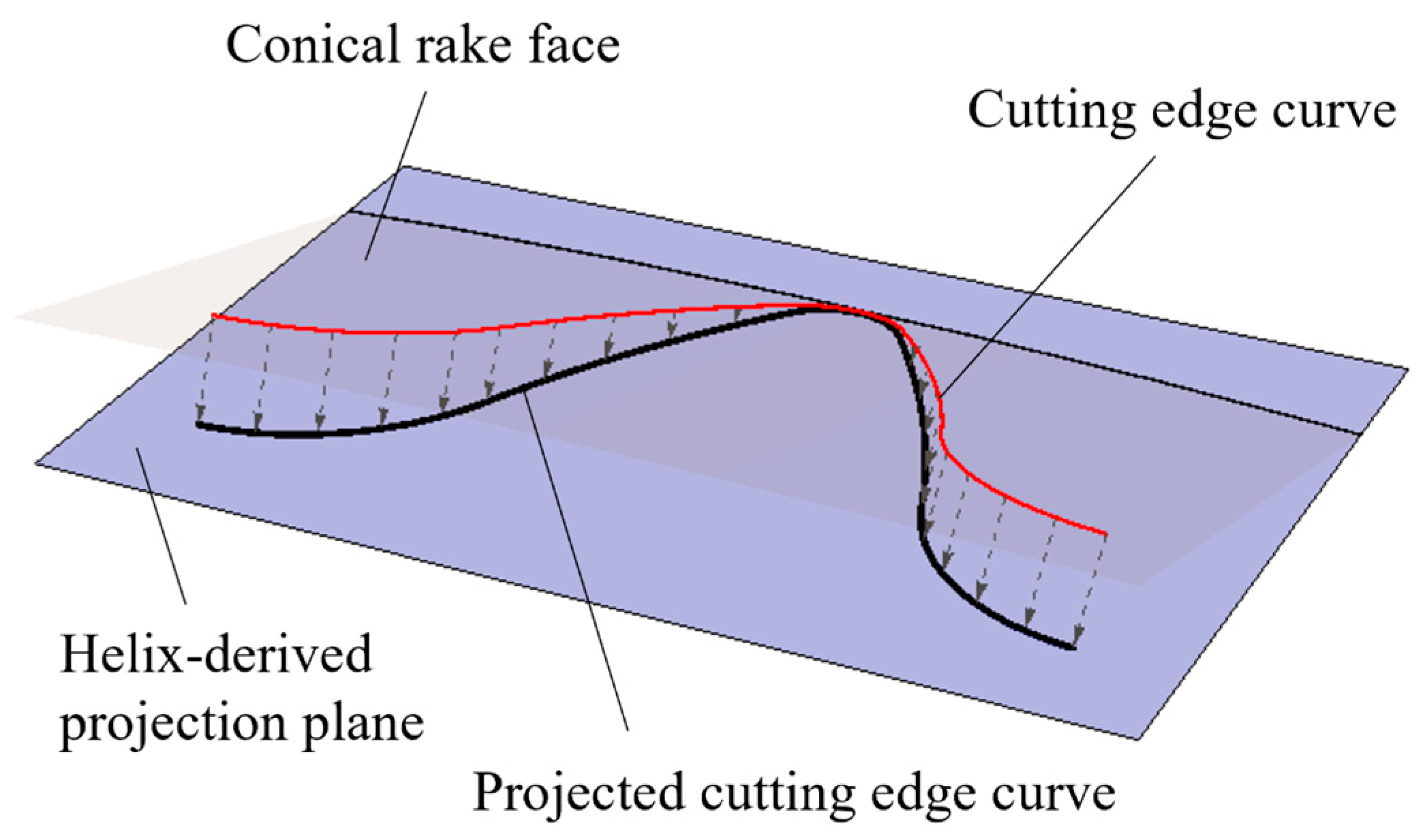
Using the projection matrix Msc, the spatial cutting edge curve is mapped onto a plane normal to the effective helical direction of the cutter. This projection preserves the intrinsic geometric characteristics of the cutting edge—such as curvature distribution and profile shape—while transforming the three-dimensional curve into a two-dimensional representation suitable for CNC grinding, tool inspection, and measurement-based reconstruction. An example of the projected cutting edge geometry is shown in Figure 7, illustrating how the spatial meshing results are transformed into a design-ready planar curve.
Figure 7.
Helix projection of the cutting edge curve.
From a physical perspective, this projection corresponds to “unwrapping” the cutting edge along the cutter’s helical path, thereby establishing a direct connection between the theoretical meshing formulation and the practical geometry used in tool manufacturing. As a result, the projected cutter profile can be compared directly with measured tool data and modified through controlled parameter adjustments.
3.7. Summary and Physical Significance of the Direct Meshing Framework
The formulation presented in this section establishes a direct surface-based meshing framework for skiving cutter edge derivation. Unlike conventional generating-gear-based approaches, which rely on auxiliary geometric abstractions, the present method enforces both positional coincidence and tangential compatibility directly on the cutter’s physical conical rake surface.
From a physical standpoint, the positional coincidence condition ensures geometric contact between the cutter and workpiece, while the tangential compatibility condition guarantees that the instantaneous relative motion is consistent with chip formation. Together, these constraints uniquely define the true cutting edge as a spatial curve on the rake surface.
Because the cutting edge is derived directly from the actual cutter geometry and the CNC-consistent skiving kinematics introduced in Section 2, the resulting formulation is inherently compatible with modern machine tools and measurement systems. The derived cutting edge is not an abstract construction, but a physically realizable curve that reflects the true cutting mechanism.
This direct meshing framework therefore provides a high-fidelity geometric foundation for the measurement-driven reconstruction, inverse meshing, and sensitivity-based compensation analyses presented in Section 4. By eliminating the geometric inconsistency of generating-gear-based models, the proposed approach enables a closed digital loop linking cutter geometry, machine kinematics, and manufacturing accuracy.
4. Experimental Verification of the Proposed Skiving Cutter Modeling Method
This section presents an experimental validation of the unified modeling framework developed in Section 2 and Section 3. The validation is designed to assess both the geometric fidelity of the direct surface-based meshing formulation and the practical effectiveness of the measurement-driven reconstruction and inverse meshing strategy. Specifically, the experimental study aims to: (1) verify that the proposed analytical formulation accurately predicts the true cutting edge geometry generated on the conical rake surface, and (2) demonstrate that incorporating measured cutting edge data significantly improves the predictive accuracy of tooth-profile simulations compared with nominal tool geometry.
To achieve these objectives, the experimental procedure integrates four key components:
- Numerical computation of the cutting edge curve using the direct surface-based meshing formulation.
- High-precision measurement of an as-manufactured skiving cutter to obtain dense 3D edge-point data.
- Spline-regularized reconstruction of the measured edge using tension-controlled splines.
- Inverse meshing simulation and machining trials performed on a six-axis skiving platform.
The combined numerical–experimental workflow enables a critical evaluation of the proposed method in terms of accuracy, numerical stability, and practical applicability in tool design and process optimization.
4.1. Experimental Setup and Measurement Procedure
A cylindrical skiving cutter was designed according to the analytical formulation established in Section 3 and fabricated from tungsten carbide using precision grinding. Particular care was taken to ensure a well-defined conical rake surface, as this surface directly governs the physical definition of the cutting edge in the proposed model.
The finished cutter was inspected using a high-resolution coordinate-measurement system. To capture the true cutting edge geometry, both the left and right flanks of all cutter teeth were scanned. The measurement system provided a spatial resolution of approximately 0.1 μm, yielding dense three-dimensional point clouds along the cutting edges. These point clouds form the raw input data for the reconstruction and inverse meshing analyses described in Section 4.2 and Section 4.3.
The workpiece gear was selected as a representative precision small-module internal gear. In recent years, small-module internal gears have been increasingly used in precision reducers for robotic-arm joints. Gear skiving is particularly suitable for machining this type of internal gear because of its high productivity and applicability to internal gear geometries. Therefore, a workpiece gear with a normal module of 0.2160 mm was adopted to demonstrate the applicability of the proposed method to such demanding industrial components.
Table 1, Table 2 and Table 3 summarize the fundamental parameters of the workpiece gear, the skiving cutter, and the machine configuration and operating conditions, respectively. These parameters determine the synchronized rotational speeds, effective skiving angles, and spatial cutter–workpiece configuration. They also serve as direct inputs to the inverse meshing simulations, ensuring full consistency between the experimental setup and the analytical model.
Table 1.
Parameters of the workpiece gear.
Table 2.
Parameters of the skiving tool.
Table 3.
Parameters of the machine setting.
High precision in cutter manufacturing and measurement is essential, as even small deviations in the cutting edge can propagate through the meshing process and significantly influence the predicted tooth-profile geometry and subsequent parameter-correction strategy.
4.2. Comparison of Cutting Edge Definitions
Based on the machine configuration and operating conditions listed in Table 1, Table 2 and Table 3, the cutting edge geometry corresponding to the fabricated skiving cutter was constructed using two different cutting edge definitions.
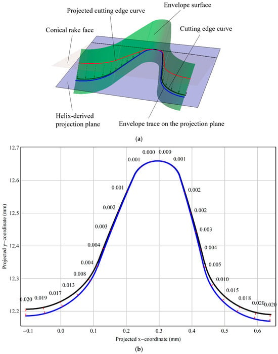
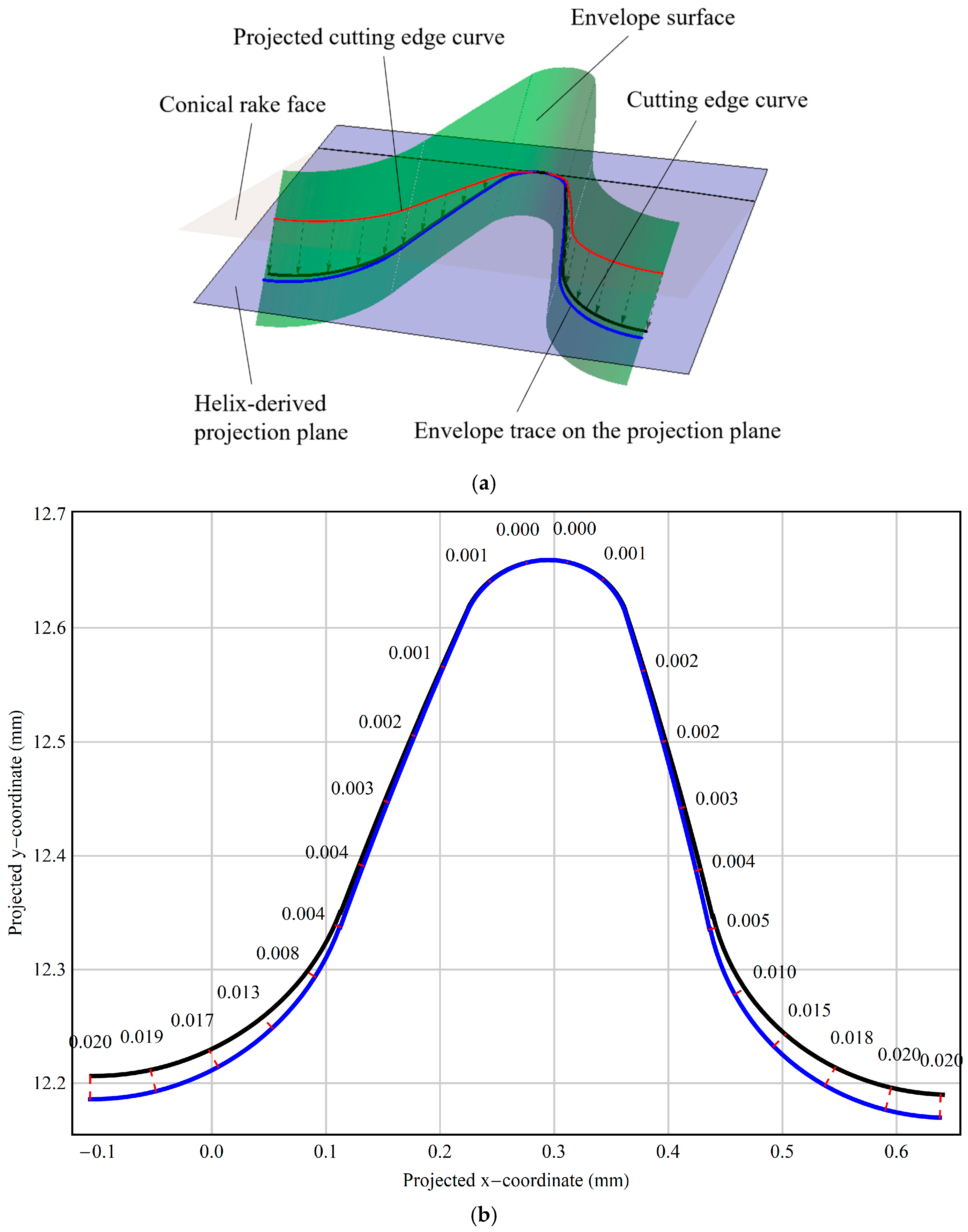
The first definition follows the helix-derived projection method proposed in Section 3, in which the spatial cutting edge on the conical rake surface is projected onto a reference plane to obtain the planar cutter profile. The second definition, adopted in several recent studies, extracts the cutting edge as a sectional curve of the meshing envelope surface.
Figure 8a compares the projected cutting edge profiles obtained using these two approaches under identical machine settings. Although both profiles originate from the same cutter geometry and kinematic conditions, noticeable differences appear in the resulting projected shapes. To quantify this discrepancy, Figure 8b presents the normal deviation between the two projected curves along the cutting edge.
Figure 8.
Comparison of cutting edge definitions under identical machine settings. (a) Comparison of projected cutting edge profiles obtained using the helix-derived projection method and the envelope-section-based method on the projection plane. (b) Comparison of the resulting end-face tooth profiles of the helical skiving cutter derived from the two cutting edge definitions, shown in terms of the normal deviation distribution (mm).
The results reveal a systematic and non-uniform deviation, indicating that the choice of cutting edge definition directly affects the geometric representation of the cutter even before any reconstruction or inverse meshing is performed. This comparison highlights the necessity of a physically consistent cutting edge definition as the foundation for accurate reconstruction and prediction.
4.3. Reconstruction of the Cutter Edge Curve from Measured Data
In the proposed framework, the theoretically derived cutter edge and the measurement-driven reconstructed cutter edge are used at different stages of the same design–measurement–verification procedure. The theoretically derived cutter edge is obtained from the specified workpiece tooth geometry through the Direct Surface-Based Meshing formulation and serves as the nominal design reference for the cutter geometry. In contrast, the measurement-driven reconstructed cutter edge is obtained from the measured discrete profile data of the manufactured cutter and represents the actual as-manufactured cutter geometry. Since both cutter edges are expressed within the same conical-rake-surface and projection framework, the reconstructed cutter edge can be used in the subsequent inverse meshing simulation to evaluate the influence of cutter manufacturing deviations on the generated workpiece tooth profile.
The spatial cutting edge curve obtained from the direct meshing formulation provides a nominal reference for the tool geometry. In practice, however, the as-manufactured cutter deviates from this ideal curve due to grinding tolerances, spindle runout, measurement noise, and wear-related effects. Accurate reconstruction of the true cutting edge geometry is therefore essential for realistic meshing analysis and reliable prediction of the resulting gear-tooth geometry.
In this study, two reconstruction strategies were evaluated:
- (a)
- Sixth-order polynomial fitting, representing a conventional approach widely used in tool inspection;
- (b)
- Tension-controlled spline interpolation based on the Wessel-Bercovici formulation [17].
After measurement, the three-dimensional edge-point clouds were transformed into the cutter coordinate system using alignment routines that minimize rigid-body deviations between the measured and nominal geometries. Polynomial fitting attempts to approximate the cutting edge curve as a single global function. While straightforward to implement, high-order polynomials are prone to oscillatory behavior, poor curvature continuity near data irregularities, sensitivity to non-uniform point spacing, and amplification of measurement noise.
To mitigate these issues, the cutting edge points were reconstructed using tension-controlled spline interpolation. The tension parameter regulates the balance between global smoothness and local shape fidelity. Increasing the tension suppresses spurious oscillations while preserving essential geometric features. As a result, tension splines provide robust noise suppression, local control of curve behavior, physically meaningful curvature evolution along the edge, and improved stability when reconstructing free-form or worn edges.
Each reconstructed cutting edge was subsequently mapped backward through the helix-derived projection described in Section 3 to obtain the corresponding spatial cutting edge curve on the conical rake surface. These reconstructed curves were then used as inputs to the inverse meshing simulations described in Section 4.4.
4.4. Inverse Meshing Simulation Using Reconstructed Cutting Edges
To evaluate the influence of reconstruction quality on tooth surface accuracy, the reconstructed cutting edge curves were inserted into an inverse meshing model. This model simulates the envelope generated by the cutter during skiving and produces the corresponding workpiece tooth surface. Accordingly, the reconstructed cutter edge used in this section represents the measured as-manufactured geometry rather than the nominal design edge, enabling the inverse meshing simulation to assess the effect of cutter edge deviations on the generated workpiece profile.
Using the cutter-workpiece kinematic relations established in Section 2 and the meshing formulation developed in Section 3, the inverse meshing pipeline proceeds as follows:
- Computation of instantaneous contact points
For each point on the reconstructed cutting edge curve pc(u), the meshing equations are evaluated to compute the corresponding set of instantaneous contact points on the workpiece surface.
- 2.
- Propagation through relative motion
Each contact point is propagated through the synchronized rotational–feed motion to obtain the spatial envelope of the generated tooth surface.
- 3.
- Extraction of the envelope surface
The envelope condition identifies the outermost locus tracing the boundary of cutter engagement.
- 4.
- Projection onto the gear normal plane
The envelope surface is intersected with the normal plane of the workpiece gear to yield the working tooth profile, which is then compared with the theoretical involute.
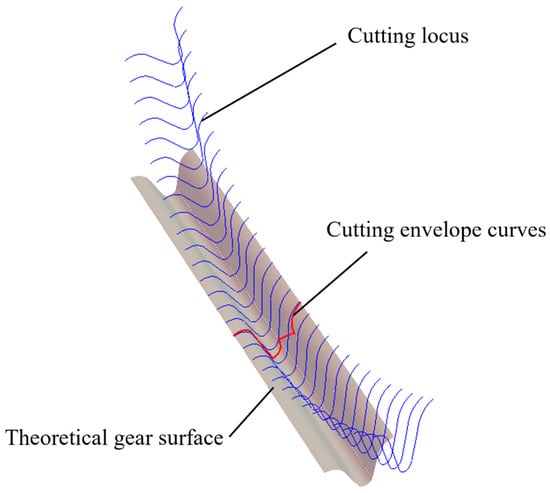
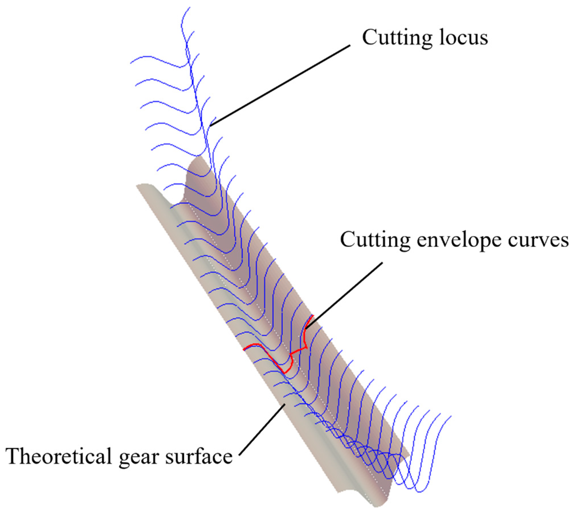
Figure 9 illustrates the computed cutting-locus envelope generated from the reconstructed cutting edge geometries.
Figure 9.
Computed cutting-locus envelope and reconstructed gear surface.
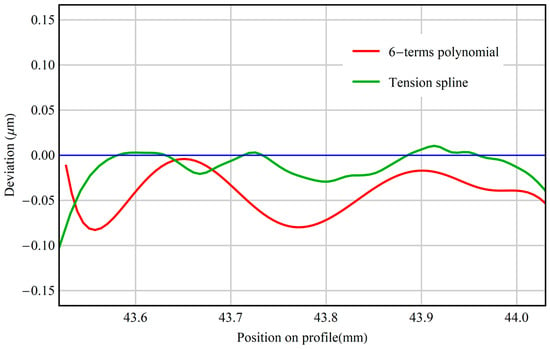
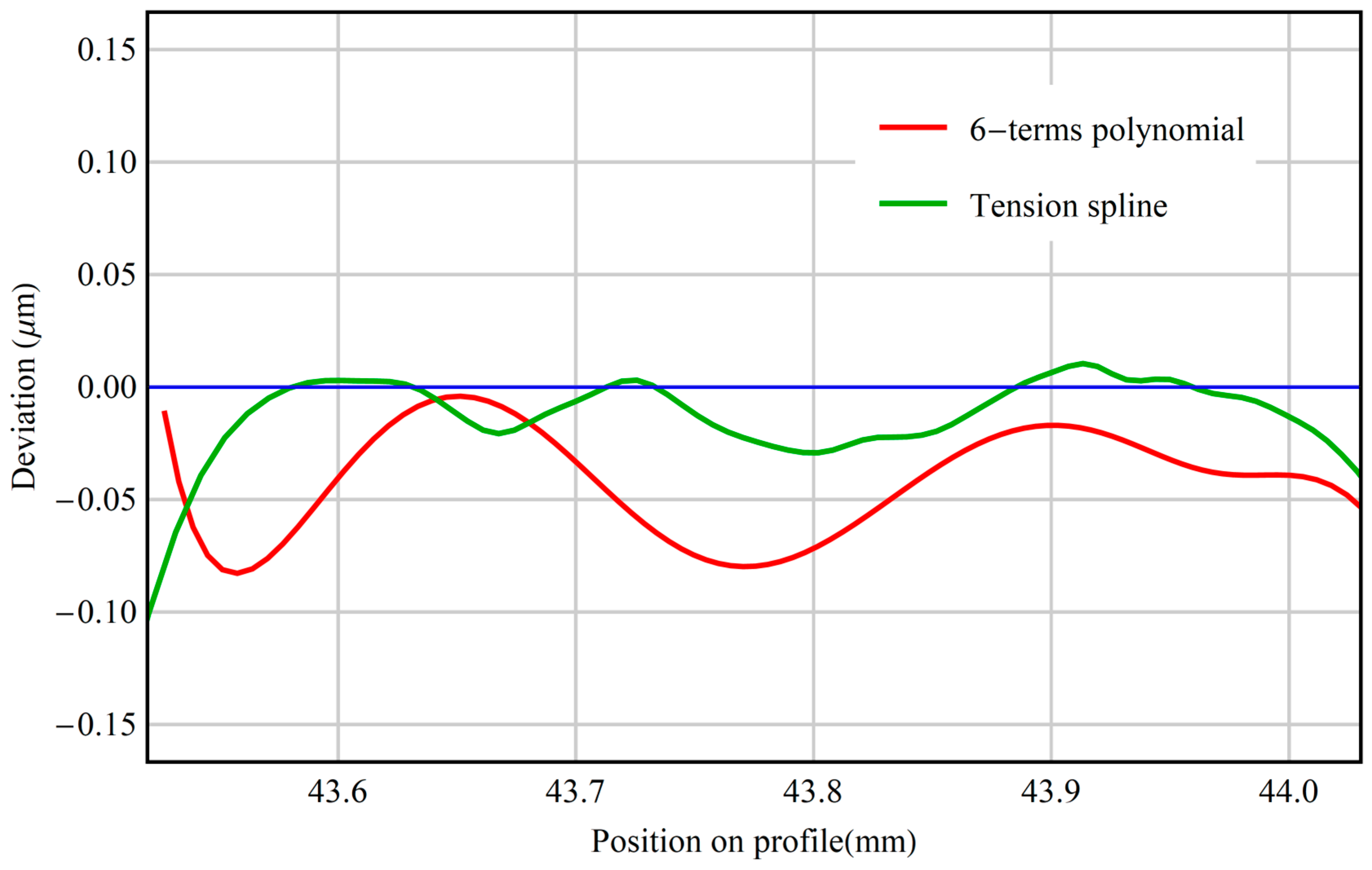
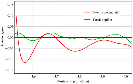
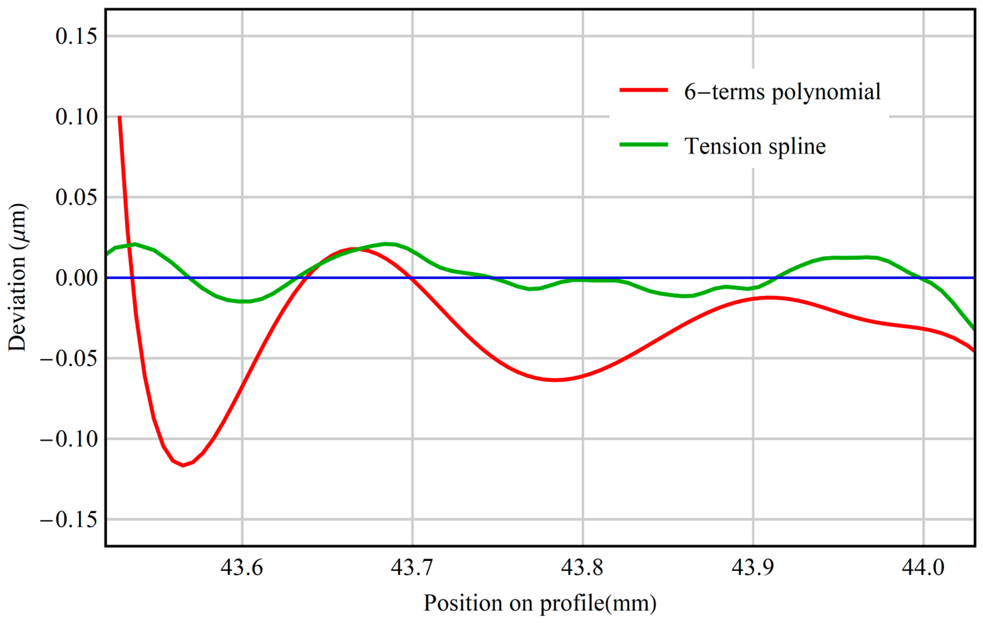
The resulting three-dimensional envelope curves were projected onto the normal plane of the gear to obtain the working tooth profiles. By comparing these profiles with the theoretical involute, the normal deviations of the left and right flanks were evaluated. Figure 10 and Figure 11 present the deviation distributions for the left and right flanks, respectively.
Figure 10.
Profile deviation on the left flank reconstructed from tension-spline and polynomial fittings.
Figure 11.
Profile deviation on the right flank reconstructed from tension-spline and polynomial fittings.
In both cases, the tension-spline reconstruction yields smaller oscillations and reduced accumulated deviation compared with polynomial fitting. Polynomial reconstruction introduces noticeable oscillations in high-curvature regions of the cutting edge, which propagate into the generated tooth surface and produce non-physical undulations and elevated flank deviations. In contrast, the spline-based reconstruction produces smooth, curvature-stable edge curves, resulting in more consistent meshing behavior and improved alignment with the theoretical geometry.
The simulation results reveal clear differences between polynomial and tension-spline reconstructions:
- Polynomial fitting introduces noticeable oscillation in the resulting envelope, particularly near the high-curvature regions of the cutting edge. This oscillation propagates into the generated tooth surface, producing nonphysical undulations and elevated flank deviations.
- Tension-spline reconstruction yields a smooth and curvature-stable edge curve, resulting in substantially more consistent meshing behavior. The corresponding envelope surfaces exhibit significantly reduced noise and improved alignment with the theoretical geometry.
These differences are reflected directly in the normal profile deviations, as presented in Figure 10 and Figure 11 for the left and right flanks, respectively. In both cases, the tension-spline method produces smaller deviation magnitudes and eliminates the oscillatory artifacts observed in the polynomial-based reconstructions.
The improved consistency in the inverse meshing results demonstrates the critical role of accurate, high-stability reconstruction in predicting the actual cutting performance of a skiving tool.
4.5. Experimental Machining Trials
To further validate the predictive capability of the proposed modeling framework under real cutting conditions, a cylindrical gear was machined using a six-axis skiving platform. The machining trials served two purposes:
- (a)
- To verify that the deviations predicted by inverse meshing correspond to those observed on an actual workpiece;
- (b)
- To demonstrate that the unified framework supports practical parameter correction and process refinement.
The skiving system consists of a cutter spindle (C1-axis), a workpiece spindle (C2-axis), a swivel axis defining the crossing angle Σ, and linear axes (X, Y, Z) enabling cutter positioning and feed. The workpiece was fabricated from spheroidal graphite cast iron, while the cutter was the tungsten-carbide tool measured and reconstructed in Section 4.3.
During machining, the cutter and workpiece were driven according to the synchronized rotational-feed kinematics defined in Section 2. The machine settings—tilt angles, crossing angle, offset angle, center distance, and feed rate—are listed in Table 3 and were selected to represent typical industrial cutting conditions for the tested module and tooth count.
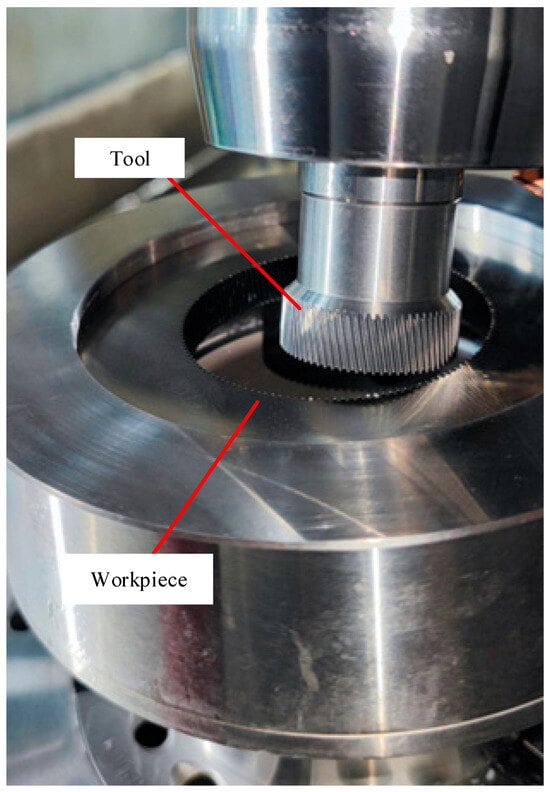
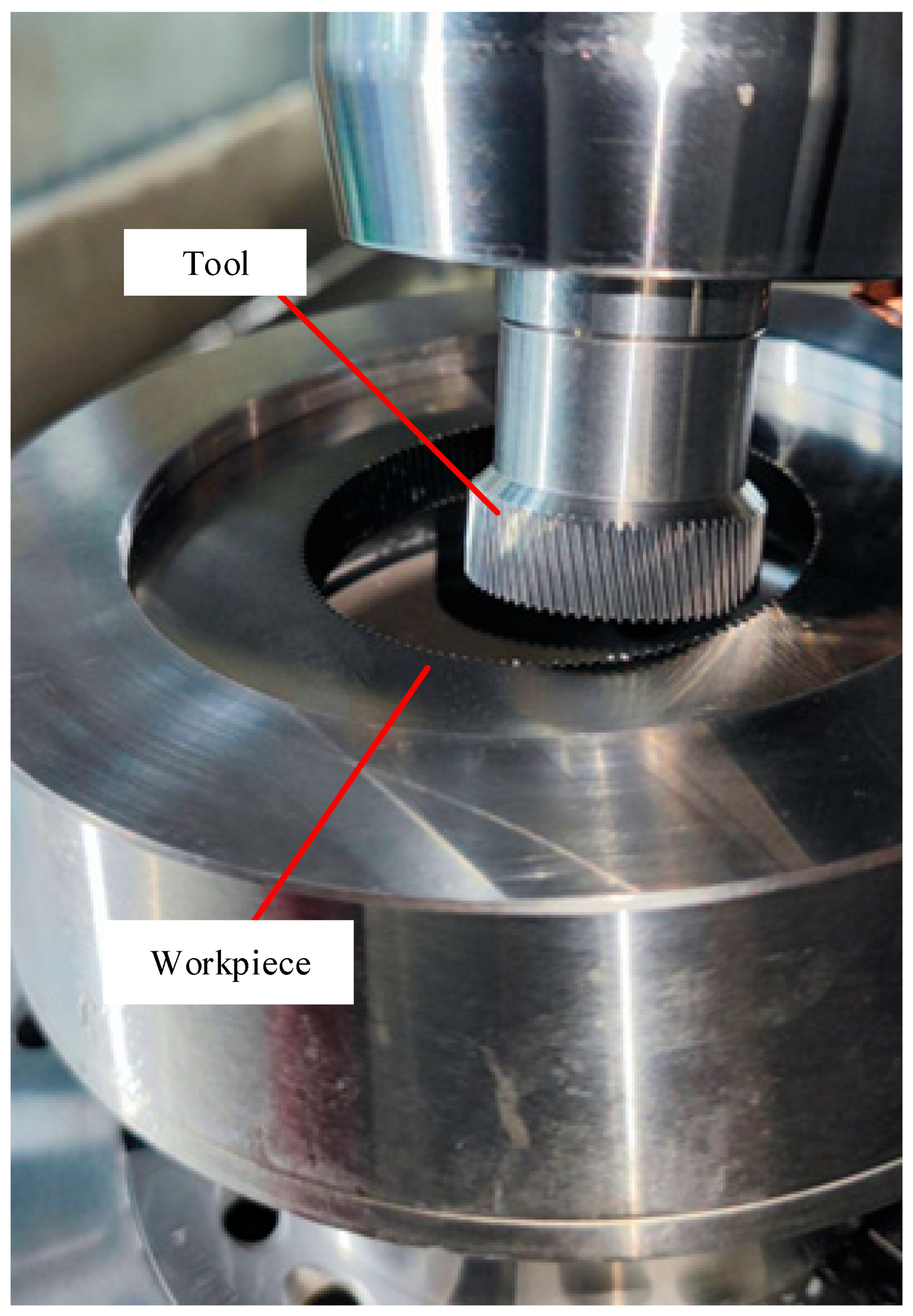
Figure 12 shows the actual configuration of the skiving cutter and workpiece mounted on the six-axis gear skiving machine. The cutter and workpiece were positioned according to the machine-coordinate mapping described in Section 2, ensuring that the experimental setup corresponded exactly to the analytical kinematic model.
Figure 12.
Configuration of the tool and workpiece mounted on the gear skiving machine.
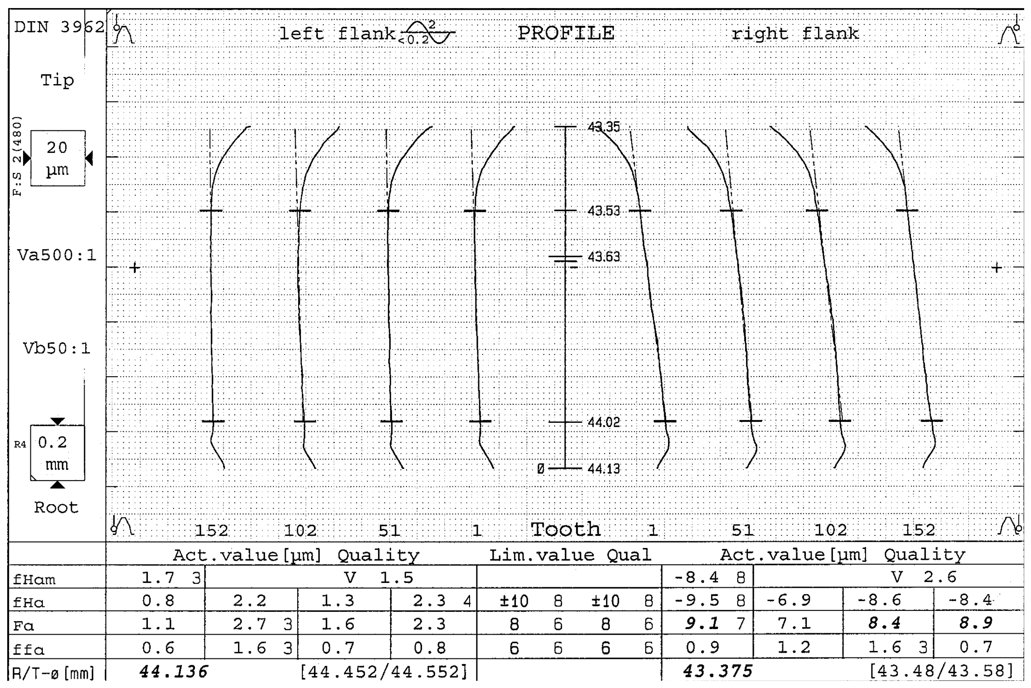
After machining, the gear was inspected using a high-precision tooth-profile measurement system. The initial tooth-profile deviations are shown in Figure 13. The measurements reveal a systematic pressure-angle shift accompanied by profile deviations that are characteristic of angular misalignment. In particular, the observed deviation pattern is consistent with small errors in the offset angle κ and the crossing angle Σ, both of which strongly influence the relative orientation between the cutter and the workpiece.
Figure 13.
Gear tooth profile measurement before parameter correction.
These experimental trends agree closely with the deviations predicted by the inverse meshing simulation. This agreement confirms that the analytical formulation accurately captures the relationship between cutting edge geometry, machine-setting parameters, and the resulting tooth-profile error. Importantly, the correspondence is not limited to overall deviation magnitude, but extends to the shape and asymmetry of the measured profiles, indicating that the dominant geometric error mechanisms are correctly identified by the model.
To further demonstrate the practical value of the unified framework, a simplified pressure-angle adjustment was applied to the reconstructed cutting edge geometry. When the adjusted edge was re-simulated through the inverse meshing model, the resulting tooth profile exhibited improved agreement with the intended involute. This result demonstrates that the reconstruction–simulation pipeline can support targeted geometric correction prior to cutter regrinding or machine adjustment.
4.6. Parameter Refinement Using SVD-Based Sensitivity Analysis
The tooth-profile measurements shown in Figure 13 exhibit systematic deviations dominated by pressure-angle errors. Such deviations typically arise from small inaccuracies in the machine’s angular settings, most notably the offset angle κ and the crossing angle Σ. Because these parameters directly control the spatial orientation of the cutter relative to the workpiece, even sub-degree errors can produce measurable profile distortion.
To formulate the parameter refinement procedure, the profile-slope deviation to be corrected is denoted by Δq, and the correction vector of the selected machine-setting parameters is denoted by Δp. Under a small-perturbation assumption, the relationship between the profile deviation and the parameter correction can be linearized as
where Ms is the sensitivity matrix. Each column of Ms is obtained by perturbing one candidate machine-setting parameter while keeping the others fixed and then calculating the corresponding change in Δq through inverse meshing simulation. In this study, Δq corresponds to the mean profile slope deviation fHαm evaluated from the gear profile measurement.
The sensitivity matrix was decomposed using singular value decomposition. The right singular vectors represent orthogonal correction directions in the machine-parameter space, while the corresponding singular values indicate the influence or observability of each direction on the profile deviation. Therefore, parameter directions associated with sufficiently large singular values and clear changes in fHαm were retained as dominant correction directions. In contrast, parameter components whose influence on fHαm was smaller than 0.1 μm within the allowable perturbation range were regarded as weakly observable and were excluded from the main correction parameters.
In this study, the allowable perturbation ranges of κ and Σ were selected based on the practical cutting conditions and feasible machine-setting adjustments, while that of as was selected according to the permissible center-distance error. Table 4 summarizes the sensitivity of fHαm to the candidate machine-setting parameters.
Table 4.
Sensitivity of the mean profile slope deviation fHαm to candidate machine-setting parameters within the allowable perturbation ranges.
The results show that κ and Σ produced observable changes in fHαm within the allowable perturbation ranges. The crossing angle Σ affected both flanks clearly, whereas the offset angle κ showed a more pronounced influence on the left flank in the present example. By contrast, the influence of as remained below the 0.1 μm criterion on both flanks. Therefore, κ and Σ were selected as the dominant correction parameters, while as was treated as weakly observable and excluded from the reduced-order correction system.
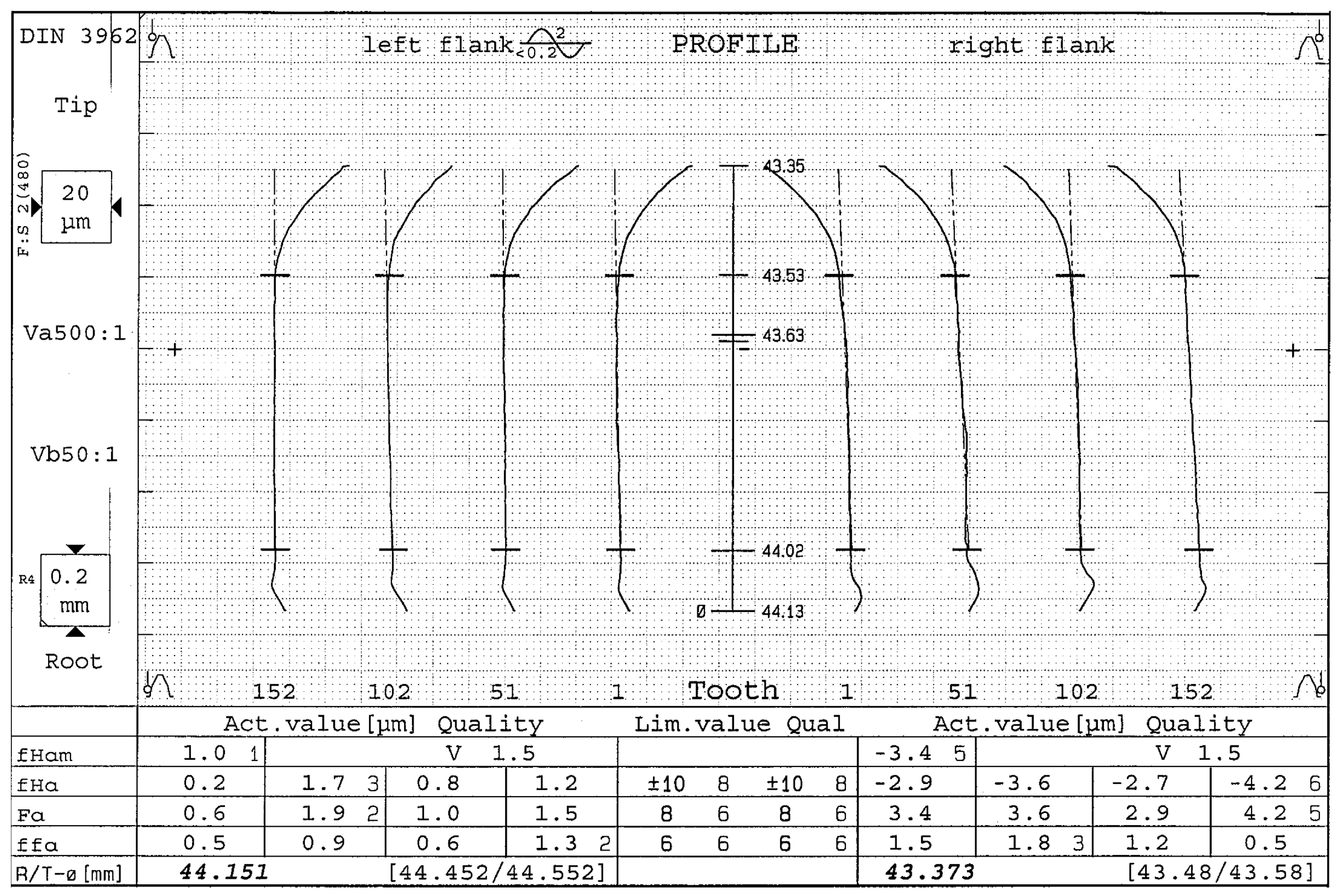
By solving the reduced-order sensitivity system, optimized corrections to κ and Σ were obtained. A second workpiece gear was subsequently machined using the refined machine settings. Figure 14 presents the corresponding tooth-profile measurements after parameter correction.
Figure 14.
Gear tooth profile measurement after parameter correction.
Compared with the initial results, the pressure-angle deviation is substantially reduced, the overall profile error decreases, and the flank shapes exhibit improved agreement with the theoretical involute. These improvements confirm that the dominant error sources were correctly identified and that the SVD-based correction strategy provides a stable and physically meaningful approach to machine-parameter refinement.
This improvement confirms that:
- The direct surface-based meshing formulation accurately captures the relationship between cutter geometry, machine settings, and the resulting tooth profile;
- The reconstructed cutter edge curves provide reliable geometric input for sensitivity evaluation;
- The unified modeling framework is effective for machine-parameter compensation in practical skiving operations.
More importantly, the SVD-based correction demonstrates that the proposed framework functions not only as an analysis tool, but also as a practical methodology for on-machine refinement and process optimization.
4.7. Summary of Experimental Findings
The combined numerical and experimental results confirm the effectiveness and practical relevance of the unified skiving cutter modeling framework proposed in this study. The validation of the proposed method was carried out in two stages. First, the theoretically derived cutter edge was verified through inverse meshing simulation. The workpiece tooth profile generated from the designed cutter edge showed a profile deviation within 0.1 μm, confirming the numerical consistency between the direct cutter edge derivation and the inverse meshing calculation. Second, the actual machined workpiece was evaluated using gear measurement data. The measured profile deviation reflects not only the designed cutter geometry but also practical machining factors, such as machine-setting errors and manufacturing deviations. Therefore, the measured deviation was further analyzed using the sensitivity-based parameter refinement procedure. This validation procedure connects the predicted workpiece profile, the measured machining result, and the subsequent parameter correction within the same design–manufacturing–verification framework. The key findings can be summarized as follows:
- Direct surface-based meshing provides accurate geometric prediction.
By enforcing positional coincidence and tangential compatibility directly on the cutter’s conical rake surface, the proposed formulation eliminates the geometric inconsistency inherent in generating-gear-based methods. The resulting spatial cutting edge curves show strong agreement with experimentally observed deviations when used in inverse meshing simulations.
- 2.
- Tension-spline reconstruction significantly enhances geometric fidelity.
Compared with polynomial fitting, tension-controlled spline reconstruction produces smoother and more curvature-stable cutting edge curves that better represent the underlying physical geometry. This improved stability directly translates into reduced oscillation and improved consistency in inverse meshing predictions.
- 3.
- Inverse meshing accurately predicts tooth-profile deviation.
The simulated deviation distributions on the left and right flanks closely match both the trend and magnitude of the experimentally measured deviations, validating the predictive capability of the direct meshing formulation.
- 4.
- CNC-consistent kinematics enable meaningful process refinement.
The six-axis kinematic mapping ensures that analytical parameters—such as offset angle, crossing angle, and synchronized rotations—are directly interpretable in terms of real machine axes. This compatibility is essential for translating simulation results into actionable machine-setting corrections.
- 5.
- SVD-based parameter correction improves machining accuracy.
Sensitivity analysis reveals that small errors in κ and Σ strongly influence pressure-angle deviation. Implementing SVD-derived corrections significantly reduces profile deviations, demonstrating the framework’s effectiveness for on-machine compensation and process optimization.
Collectively, these results demonstrate that the proposed method forms a complete, measurement-driven digital chain capable of:
- (a)
- Accurately characterizing real cutting edge geometry;
- (b)
- Predicting tooth-profile deviation through physically grounded meshing analysis;
- (c)
- Guiding machine-parameter refinement for improved tooth quality.
5. Conclusions
This study proposed a unified, measurement-driven modeling framework for cylindrical gear skiving that resolves fundamental geometric inconsistencies present in conventional analytical and industrial approaches. By formulating the meshing and compatibility conditions directly on the cutter’s physical conical rake face, the proposed method eliminates the reliance on a virtual generating gear and provides a geometrically and physically consistent description of the true cutting edge formation mechanism.
The direct surface-based meshing formulation ensures that the cutting edge curve emerges naturally from positional coincidence and tangential compatibility on the rake surface, rather than from projected or sectioned approximations. This treatment establishes a direct and unambiguous relationship between cutter geometry, machine kinematics, and the resulting tooth surface envelope, forming a rigorous foundation for predictive skiving analysis.
To bridge analytical modeling with real cutter geometry, a tension-controlled spline reconstruction strategy was introduced for measured cutting edge data. Compared with high-order polynomial fitting, the spline-regularized approach effectively suppresses oscillatory artifacts, stabilizes curvature evolution, and improves robustness under measurement noise and non-uniform point spacing. When integrated into inverse meshing analysis, the reconstructed cutting edges generate envelope surfaces and tooth profiles that closely match experimental measurements, demonstrating the importance of geometrically stable reconstruction for reliable prediction.
A CNC-consistent six-axis kinematic model was further established to ensure direct compatibility between analytical parameters—such as offset angle, crossing angle, synchronized rotations, and axial feed—and the actual axis architecture of modern skiving machines. This compatibility enables a seamless transition from simulation to practice and allows the analytical framework to be used not only for analysis but also for practical parameter refinement and process optimization.
Experimental machining trials validated the predictive capability and practical relevance of the proposed framework. The tooth-profile deviations observed in the initial machined gears were accurately explained by the inverse meshing simulations. Through SVD-based sensitivity analysis, targeted corrections to the offset and crossing angles were identified and implemented, leading to a substantial reduction in pressure-angle deviation and overall profile error. The improved agreement between predicted and measured tooth profiles confirms that the unified model is suitable for both offline simulation and on-machine compensation.
Overall, this work establishes a complete digital chain for skiving cutter modeling that integrates:
- (1)
- Direct surface-based meshing on the conical rake face;
- (2)
- Spline-regularized reconstruction of measured cutter geometry;
- (3)
- CNC-compatible kinematic representation;
- (4)
- Experimentally validated, sensitivity-based parameter refinement.
The proposed framework enhances geometric fidelity, reduces modeling uncertainty, and provides a practical foundation for advanced skiving cutter design, performance prediction, and machining optimization. Future work will extend the approach to include dynamic cutting effects, tool-wear evolution, and data-driven parameter tuning, further improving the adaptability and intelligence of skiving-process modeling.
Author Contributions
Conceptualization, W.-J.C. and Z.-H.F.; methodology, W.-J.C. and Z.-H.F.; software, W.-J.C.; validation, W.-J.C. and Z.-H.F.; formal analysis, W.-J.C.; investigation, W.-J.C.; data curation, W.-J.C.; writing—original draft preparation, W.-J.C.; writing—review and editing, W.-J.C. and Z.-H.F.; visualization, W.-J.C.; supervision, Z.-H.F.; project administration, Z.-H.F. All authors have read and agreed to the published version of the manuscript.
Funding
This research received no external funding.
Data Availability Statement
The data presented in this study is available on request from the corresponding author.
Conflicts of Interest
The authors declare no conflicts of interest.
Nomenclature
| as | center distance between cutter and workpiece axes |
| R | cone radius of the rake surface |
| Rc | maximum cone radius of the rake surface |
| γc | cone angle of the rake surface |
| r | radial parameter on the conical rake surface |
| ρ | angular parameter on the conical rake surface |
| Nc | number of teeth of the cutter |
| Nw | number of teeth of the workpiece |
| mtw | transverse module of the workpiece |
| rc | cutter pitch radius |
| rw | workpiece pitch radius |
| βc | cutter helix angle |
| βw | workpiece helix angle |
| ϕc | rotational angle of the cutter |
| ϕw | rotational angle of the workpiece |
| ωc | angular velocity of the cutter |
| ωw | angular velocity of the workpiece |
| ωh | additional rotational component associated with helical motion |
| θb | back-tilt angle |
| θs | side-tilt angle |
| κ | offset angle |
| Σ | crossing angle |
| κ0, Σ0 | initial (preset) offset and crossing angles |
| qf | axial feed displacement |
| fw | axial feed rate of the workpiece |
| k | index of repeated engagements on the same tooth flank |
| Sc = {xc, yc, zc} | cutter coordinate system |
| Sw = {xw, yw, zw} | workpiece coordinate system |
| So, Sv | auxiliary coordinate systems used in coordinate transformations |
| rr | position vector of a point on the conical rake surface |
| pc | parametric position vector of a workpiece tooth- surface point expressed in the cutter coordinate system |
| pw | parametric position vector of a workpiece tooth surface point expressed in the workpiece coordinate system |
| Mcw | transformation matrix from the workpiece coordinate system to the cutter coordinate system |
| Msc | transformation matrix for helix-derived projection |
| u | profile-direction parameter (workpiece or cutter; context-dependent) |
| v | lead-direction parameter (workpiece or cutter; context-dependent) |
| nc | normal vector of the workpiece tooth surface in the cutter coordinate system |
| nr | normal vector of the conical rake surface |
| τr | intersection-direction vector between the workpiece surface and the rake surface |
| nm | admissible rake-tangent-plane normal lying in the rake tangent plane |
| vc | relative velocity of the workpiece surface induced by cutter rotation ϕc |
| vm | Rake-tangent-plane velocity (projection of vc into the rake tangent plane) |
References
- Adams, G. Method of Cutting van Gears Using a Gear-like Cutting Tool with Cutting Edges on the Face Surfaces of the Teeth. Germany Patent DE243514C, 16 February 1912. [Google Scholar]
- Seibicke, F.; Müller, H. Good things need some time. Gear Solut. 2013, 74–80. [Google Scholar]
- Stadtfeld, H.J. Power skiving of cylindrical gears on different machine platforms. Gear Technol. 2014, 31, 52–62. [Google Scholar]
- Tsai, C.Y. Mathematical model for design and analysis of power skiving. Mech. Mach. Theory 2016, 95, 195–208. [Google Scholar] [CrossRef] [Scilit]
- Tsai, C.Y. Power-skiving tool design method for interference-free involute internal gear cutting. Mech. Mach. Theory 2021, 164, 104396. [Google Scholar] [CrossRef] [Scilit]
- Tsai, C.Y. Simple mathematical approach for analyzing gear tooth profile errors of different gears cut using same power-skiving tool. Mech. Mach. Theory 2022, 177, 105042. [Google Scholar] [CrossRef] [Scilit]
- Tsai, C.Y. Integrated mathematical approach for design and manufacturing of power-skiving tool for interference-free involute internal gear cutting. Mech. Mach. Theory 2023, 180, 105172. [Google Scholar] [CrossRef] [Scilit]
- Shih, Y.P.; Li, Y.J. A novel method for producing a conical skiving tool with error-free flank faces for internal gear manufacture. J. Mech. Des. 2018, 140, 043302. [Google Scholar] [CrossRef] [Scilit]
- Shih, Y.P.; Li, Y.J.; Lin, Y.-C.; Tsao, H.-Y. A novel cylindrical skiving tool with error-free flank faces for internal circular splines. Mech. Mach. Theory 2022, 170, 104662. [Google Scholar] [CrossRef] [Scilit]
- Luu, T.T.; Wu, Y.R. A novel correction method to attain even grinding allowance in CNC gear skiving process. Mech. Mach. Theory 2022, 171, 104771. [Google Scholar] [CrossRef] [Scilit]
- Guo, E.; Hong, R.; Huang, X.; Fang, C. Research on the cutting mechanism of cylindrical gear power skiving. Int. J. Adv. Manuf. Technol. 2015, 79, 541–550. [Google Scholar] [CrossRef] [Scilit]
- Guo, Z.; Mao, S.M.; Li, X.-E.; Ren, Z.-Y. Research on the theoretical tooth profile errors of gears machined by skiving. Mech. Mach. Theory 2016, 97, 1–11. [Google Scholar] [CrossRef] [Scilit]
- Klocke, F.; Brecher, C.; Löpenhaus, C.; Ganser, P.; Staudt, J.; Krömer, M. Technological and simulative analysis of power skiving. Procedia CIRP 2016, 50, 773–778. [Google Scholar] [CrossRef] [Scilit]
- Zheng, F.Y.; Zhang, M.D. Research on the tooth modification in gear skiving. J. Mech. Des. 2018, 140, 084502. [Google Scholar] [CrossRef] [Scilit]
- Bergs, T.; Georgoussis, A.; Löpenhaus, C. Development of a numerical simulation method for gear skiving. Procedia CIRP 2020, 91, 352–357. [Google Scholar] [CrossRef] [Scilit]
- Ren, Z.; Fang, Z.; Kobayashi, G.; Kizaki, T.; Sugita, N.; Nishikawa, T.; Kugo, J.; Nabata, E. Influence of tool eccentricity on surface roughness in gear skiving. Precis. Eng. 2020, 66, 170–176. [Google Scholar] [CrossRef] [Scilit]
- Wessel, P.; Bercovici, D. Interpolation with splines in tension: A Green’s function approach. Math. Geol. 1998, 30, 77–93. [Google Scholar] [CrossRef] [Scilit]

Disclaimer/Publisher’s Note: The statements, opinions and data contained in all publications are solely those of the individual author(s) and contributor(s) and not of MDPI and/or the editor(s). MDPI and/or the editor(s) disclaim responsibility for any injury to people or property resulting from any ideas, methods, instructions or products referred to in the content. |
© 2026 by the authors. Licensee MDPI, Basel, Switzerland. This article is an open access article distributed under the terms and conditions of the Creative Commons Attribution (CC BY) license.