


Abstract
Elevators exemplify mechatronics by integrating mechanical, electrical, and software systems. This paper discusses a four-story tabletop elevator model developed to demonstrate mechatronics and automation concepts in engineering education. The system utilized an Arduino MEGA microcontroller, 3D-printed components, an integrated servo motor, and standard electronics to replicate commercial elevator logic. The physical design features a ball screw linear actuator for vertical motion. It replicates dual-door systems with one door on the moving car and fixed doors at each floor that open simultaneously upon arrival. Development included designing the physical model, prototyping control algorithms, and integrating hardware and software. The model successfully demonstrated key functions: automatic dual-door operation, safety interlocks, smooth inter-floor motion, responsive floor-selection buttons with LED feedback, and efficient routing algorithms prioritizing requests based on current direction and location. Performance testing confirmed that the model accurately replicates modern elevator behavior and serves as an effective educational tool.
1. Introduction
Elevators are one of the most ubiquitous mechatronic applications in the modern world, with more than seven billion elevator trips taken annually. Their utility and increasing abundance have helped transform cities and architecture over the past century [1]. Such a system is an excellent means of educating engineering students on important mechatronic principles. The elevator, at the surface level, achieves a rather simple task, but in reality, it demands careful and thorough planning in both hardware and software design.
This project aims to create a simplified, tabletop elevator model that mimics the control behavior of real-world systems, serving as an educational tool for engineering students. A typical elevator consists of a carriage that transports passengers or cargo, a counterweight, a motor, sheaves (pulleys), a control system, and user interface components such as buttons. Dating back to the 17th century, conventional elevators have used counterweights for efficiency in mechanical lifting [2].
While there is extensive literature on the mechanical design and dynamics of traditional elevator systems [3,4], this project focuses primarily on control logic, programming, and user interfacing. A ball screw actuator simplified construction and provided a more compact design and robustness for transportation between demonstrations.
Real elevator elements were still emphasized in the model, including two doors: one attached to the moving car and another fixed at each floor. When the car arrives at a floor, both doors open simultaneously to allow entry and exit. This functionality was replicated in the model and exemplifies the integration of electronic and mechanical components to create an efficient engineering solution.
Similar educational mechatronics projects scaling real-world systems include: a colored-blocks sorting system [5], a reconfigurable assembly line [6], an autonomous car [7], and an active pendulum modeling the damping of crane swaying [8]. These projects achieve a similar goal to the model elevator in demonstrating system integration.
Existing literature discusses the control aspects of elevator design, namely the different methods of elevator routing logic (e.g., first-come-first-serve, simple heuristic, fuzzy logic), which provides a valuable comparison to the method employed for the tabletop model. One such article discusses the simple heuristic approach, similar to this project. The logic dictates that the elevator only serves requests in the direction of travel (up/down) to minimize backtracking, and that direction reversals should only occur once the elevator has served all requests in the current direction [9]. This behavior appears most often in real-life elevators and thus was chosen as the logic that the tabletop model should replicate. However, the tabletop model diverges from the scope of reference [9] in its application of the heuristic method to a mechanical design, rather than being strictly a focus on elevator efficiency and optimization of passenger wait times. While additional, more complex strategies, including algorithm optimization [10], fuzzy logic [11], and machine learning [12], also exist, these methods exceed the educational goals of this undergraduate-focused model.
Some studies have reported using elevators as educational tools. One such work discusses a three-story elevator developed as an undergraduate engineering class project [13]. However, the physical design and functionality of that model differ from this approach because doors are not included. Another work focuses on an entire course in motion control for undergraduate mechatronics students, with a final elevator project incorporating low-cost materials and a modular design aimed at making an accessible educational model [14]. Furthermore, one paper discusses the design of a four-story elevator controlled via PLC as a project for groups of students studying electrical and electro-mechanical engineering [15], with a main focus on elevator motion and user interfacing, recommending the integration of an actuated door into the model for future work.
In contrast to the above works, the present work’s contribution is the deliberate integration of real-world elevator features such as dual-door synchronization, servo actuation, LED-based floor indication, and an intuitive user interface into a compact, transportable platform designed specifically for engineering education. While classical control methods are intentionally employed to maintain accessibility for undergraduate students, the combination of features replicating real elevator behavior at this level of fidelity represents a novel educational tool not reported in the existing literature on elevator-based educational models. This approach is intended to provide engineering students with a more comprehensive understanding of mechatronics integration in familiar, everyday systems and allow a broader audience to understand the system through hands-on, public demonstrations.
The remainder of this paper is organized as follows: Section 2 covers the system design, including physical elevator model and electrical hardware; the control architecture; and the system cost. Section 3 presents the results, including the experiments conducted comparing the dynamic performance and timing of the tabletop elevator to real-world systems. Section 4 provides a final discussion of the project, as well as recommendations for further improvements or future work based on the results of this study.
2. Materials and Methods
2.1. Mechanical Design
The tabletop elevator consists of four main components: the drive motor and stage, the physical model of the four floors, the carriage and automatic door assembly, and the control buttons that model the inside panel and outside controls of an elevator.
2.1.1. Drive Motor and Linear Stage
Rather than replicating the traditional rope-and-counterweight system used in real elevators, this model utilizes an integrated servo-and-ball screw setup. This allowed for a greater emphasis on recreating the control and logic aspects of true elevators while maintaining the general mechatronic design and reducing the model’s footprint. Core features of a real elevator were still implemented in the model, including safety sensors in the doors, buttons with indicator lights, and synchronized inside/outside doors.
A ball screw was coupled to a Teknic ClearPath MCPV-integrated servo motor (Teknic, Inc., Victor, NY, USA) to emulate smooth elevator travel from floor to floor. The integrated servo motor combines a brushless DC motor, an encoder, and drive electronics into a single compact unit that reduces the cost and hardware footprint. The motor was set to a four-position home-to-hard-stop configuration, with vertical floor-to-floor distance converted from millimeters to encoder counts and a hard stop at the top of the model. The built-in trajectory control functions allowed for velocity and acceleration control, ensuring smooth travel between floors. The motor also provides feedback to the microcontroller via its digital HLFB line, which communicates when the motor has reached the desired position, allowing the microcontroller to execute the appropriate commands for arrival upon a new floor. These integrated motor feedback and positioning features eliminate the need for external limit switches.
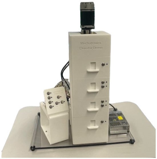
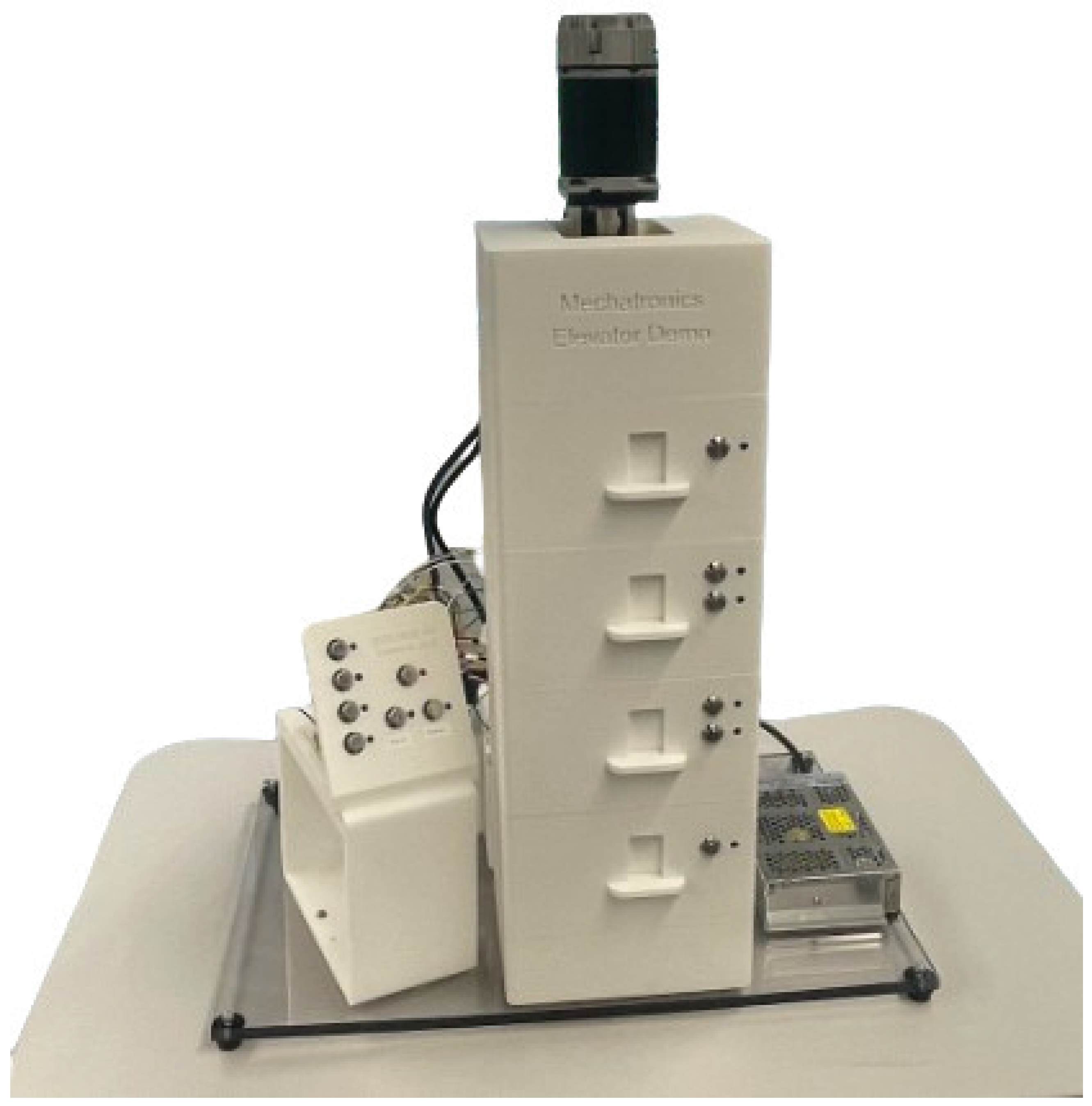
Figure 1 displays the complete model of the elevator, consisting of four floor modules, a base, and a top lid. The floor modules and base/lid were designed to surround the ~400 mm (16 in.) linear stage and ball screw, with space allocated for the integrated servo motor. A four-story elevator was chosen because it requires more complex routing logic than two- or three-story systems, while remaining practical for a transportable educational demo. The two intermediate floors create additional complexity since passengers at these levels can request travel in either direction, requiring optimized routing decisions. The base was designed to friction-fit around the stage and includes compartments for counterweights that help balance the tipping moment created with a large mass (motor) at the top end of the ball screw. The motor location was determined to be better exposed on top of the assembly to enhance heat transfer through natural convection and allow for modularity if a different motor were to be used.
Figure 1.
Completed elevator model with four floors and a panel (left) to represent the inside buttons.
2.1.2. Elevator Frame and Outside Doors
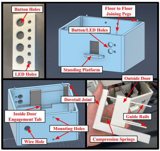
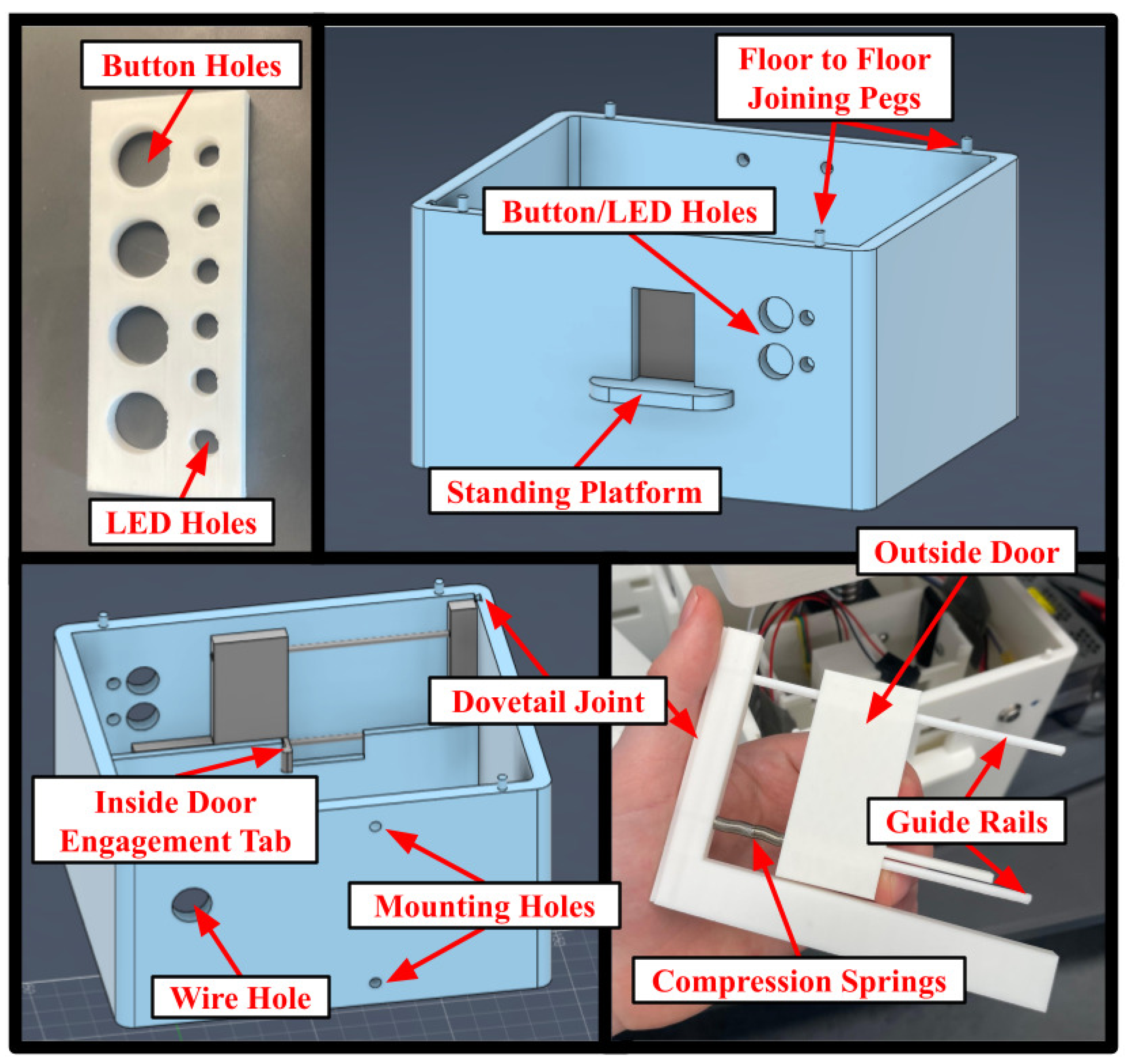
Each individual floor includes at least one button (to call the elevator) and a corresponding LED that lights up when the button is pressed. Figure 2 depicts how the hole sizes were selected based on tolerance testing with varying diameters to account for shrinkage due to the materials used and the orientation of the print (vertical). Many researchers have studied finish quality for additive manufacturing (AM), especially as fused deposition modeling (FDM) printing and access to inexpensive prototyping materials such as PLA are increasing. One paper recommends a hole horizontal expansion parameter of 0.13 mm to compensate for inherent manufacturing discrepancies with AM through FDM [16]. The model elevator required case-specific testing due to a different 3D printer configuration, but the existing research provided a baseline for the necessary dimensional increase of the holes. Tolerancing and print orientation played a role in all the components in Figure 2, as the dovetail joints needed to mate, the guide rails needed to allow smooth travel for the door, and the button/LED holes needed to provide a friction-fit for those components to eliminate the need for additional fasteners. Each floor had a small door hole paired with an outcropping to represent where a person would stand while waiting for the elevator to arrive. Inside the frame, there is a slot for the outside door components to slide in.
Figure 2.
Individual floor CAD model with tolerance testing results and dovetail-jointed outside door rails.
The outside door of an elevator is constantly closed until the carriage arrives at the corresponding floor. Figure 2 depicts the mechanism to achieve this feature in the model: a custom outside door piece, springs, and a guide rail. Compression springs hold the outside door in place at their relaxed length. Two were used in series to reduce the overall spring constant and ensure minimal resistance when the elevator doors open. A guide rail system was designed to friction-fit into the individual floor frames with a dovetail joint, allowing the door piece to slide and be pushed by the springs. The outside door itself has a small tab that extends beyond the channel in the individual floor frame that restricts its motion. This tab allows the motorized door in the elevator carriage to engage when the inside and outside doors need to be opened in conjunction.
Modular joining strategies were used throughout the design for ease of assembly and continual iteration. The dovetail joints between the guide rail and frame allowed for ease of insertion without fasteners for a component that was iterated upon during testing. Between floors, joining pegs allow for alignment when mounting to the stage and quick disassembly during testing or maintenance. These methods are further beneficial during educational demonstrations when the individual components can be explained without costly disassembly time or tooling requirements.
2.1.3. Elevator Carriage and Inside Door
The model of the elevator carriage incorporates the key functions of a true elevator carriage but involves intricate and novel design due to tight spacing tolerances, motion of the cables, complicated features, and a small budget. The main difficulty was getting everything to fit within a 90 mm by 90 mm by 50 mm constraint. The largest component is a compact two-phase stepper motor with a ball screw and linear stage that allows for linear motion of the inside door. The stage selected had a small footprint and was very inexpensive, but it had low torque output due to a low pitch on the ball screw and a maximum operating power of only 1.5 W. This low torque proved challenging when engaging the carriage door with the doors on the outside of each floor.
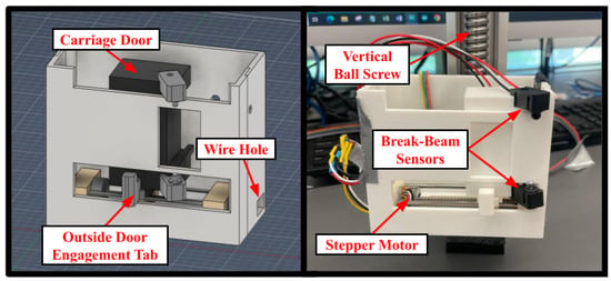
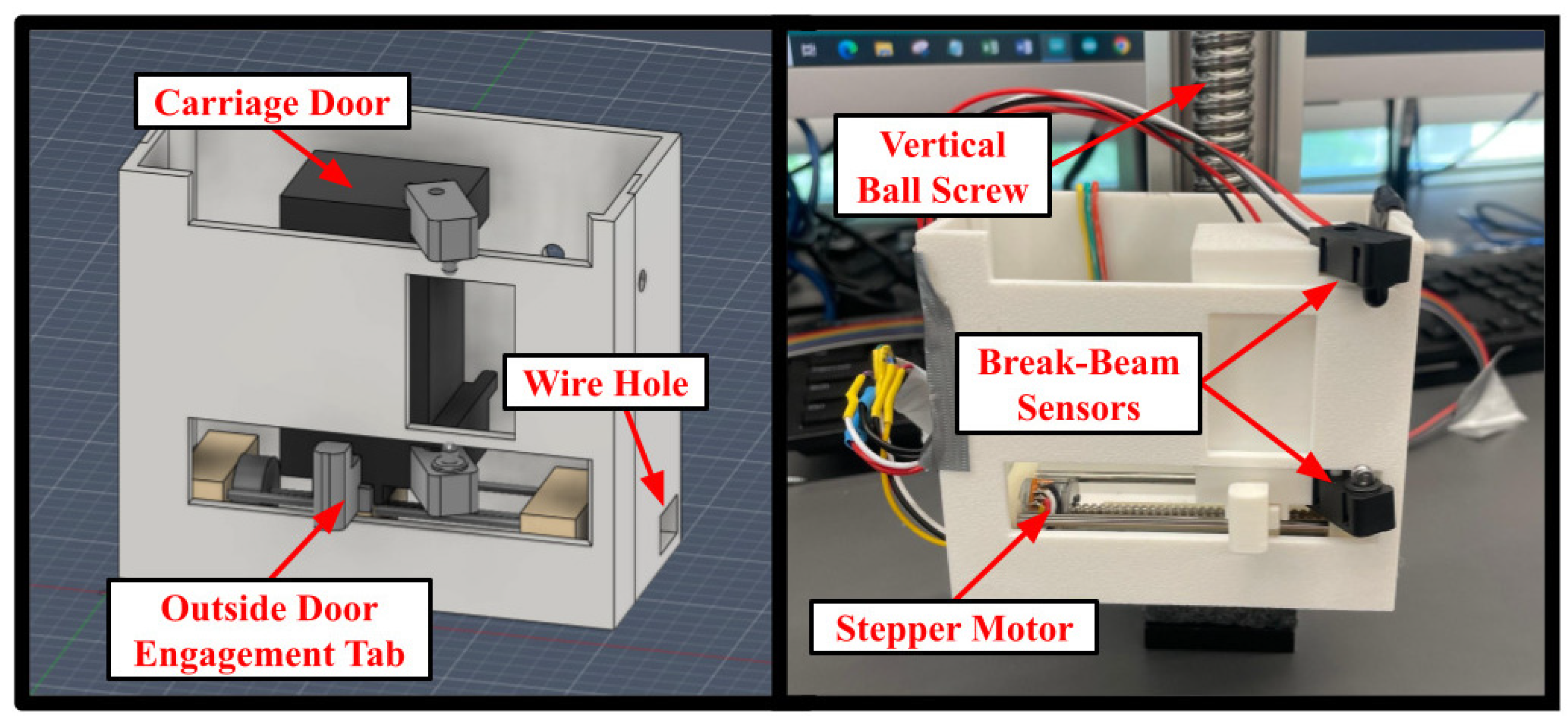
The carriage incorporates multiple sensors for operation. There are two Hall-effect sensors that act as limit switches to determine when the door is in the open or closed positions. The door also includes a break-beam sensor that prevents the door from closing if an obstacle is detected. This is done to replicate the safety features of a true elevator, which prevents users from being injured when the doors close. Figure 3 shows the CAD model for the carriage with all the individual components, along with the physical model, including the necessary wires.
Figure 3.
Elevator carriage with inside door and sensors; CAD model (left) and physical parts (right).
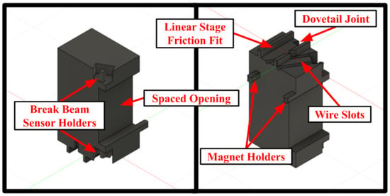
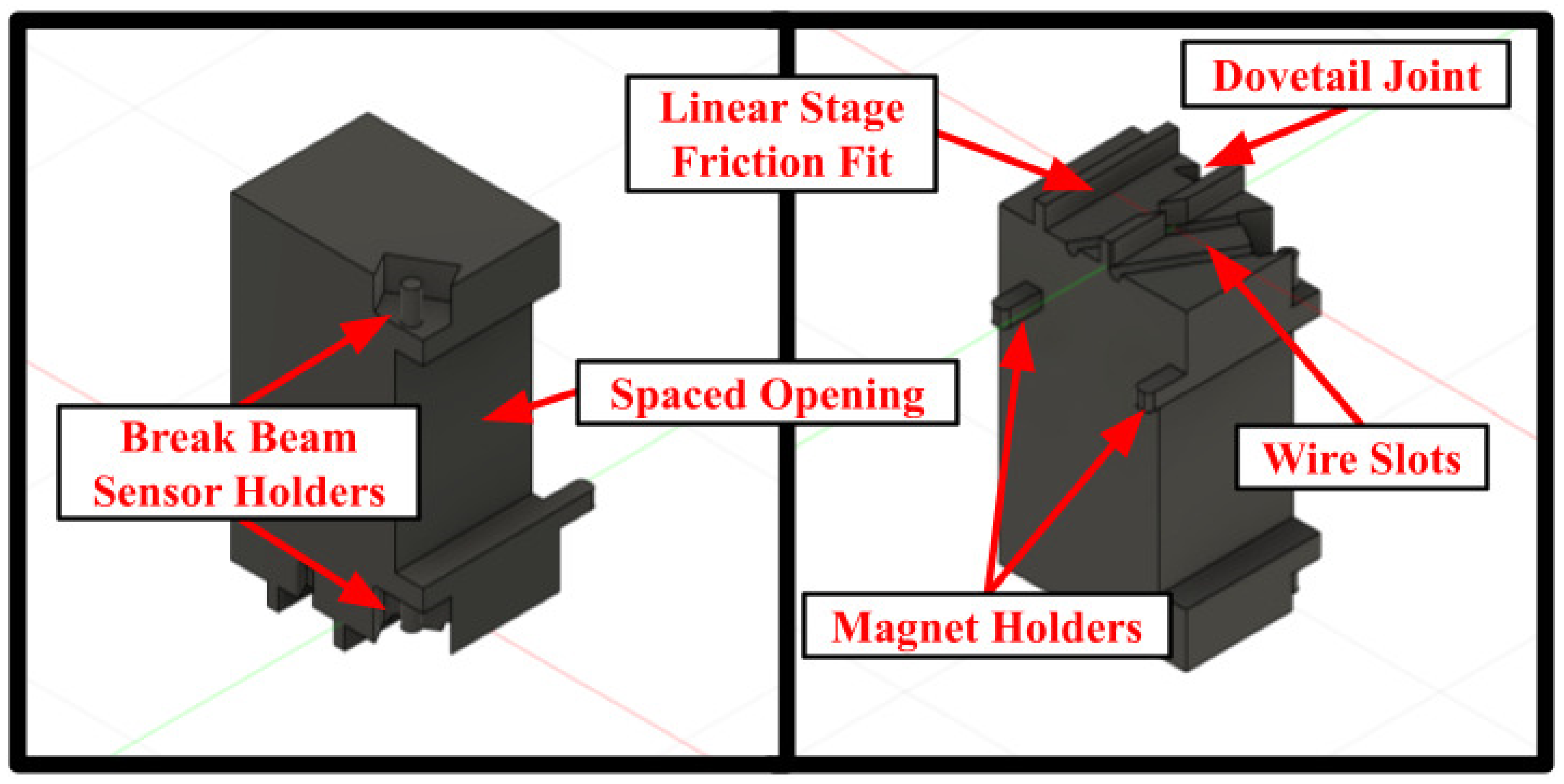
The carriage door alone is a highly complex and integral part of the model elevator’s design. Figure 4 shows how it is designed to friction-fit onto the sliding piece of the linear stage, but it allows spacing for wires to slide underneath. It requires aligned mounting of the transmitter and receiver for the break-beam sensor, angled at 60° to allow for overhang in front of the opening. It contains a dovetail joint opening for interchangeable tabs that engage with the outside door pieces. Testing took place to determine the optimal dimensions of this piece. The door also contains space for magnets to be mounted that trip the Hall-effect sensors in the desired open and closed positions.
Figure 4.
A Fusion360 model of the carriage door.
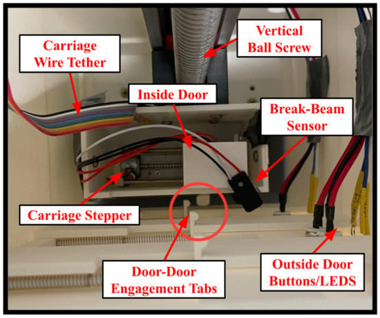
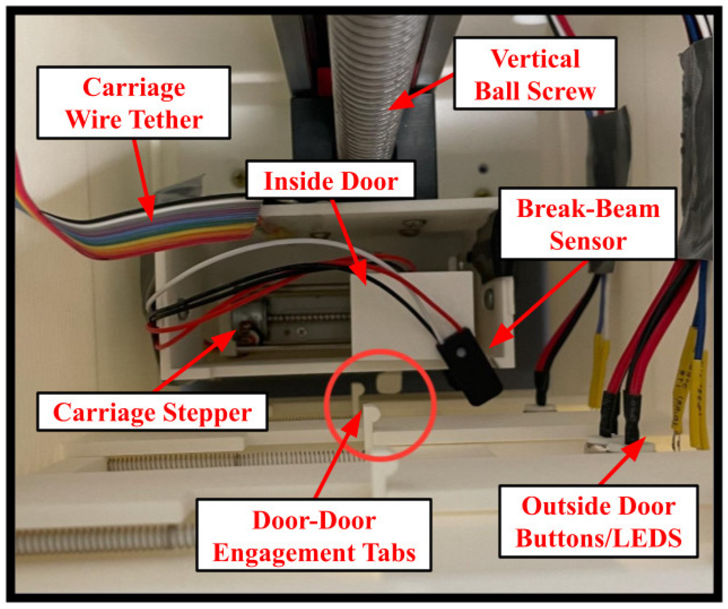
On the right side of the door, there is a rectangular cutout that allows for proper alignment of the carriage and outside frame doors during opening and closing sequences. The dimensions of this cutout were measured with the full CAD assembly, then verified with real-world testing. Additional testing was performed to ensure that the tab meshed with the outside doors without interfering during rising or descent. Figure 5 shows a top view of the model elevator shaft with the carriage electronics, engagement tabs, and other key door components highlighted.
Figure 5.
Top view for alignment of carriage with outside doors.
2.1.4. Inside Carriage Control Buttons and Wiring
As in real elevators, pushbuttons provide the simplest means of interfacing with the elevator’s microcontroller. Normally-open momentary buttons were chosen over latching-type buttons. When the microcontroller detects a button press, the program changes the value of the associated request variable to remember that the request was made. As part of the user interface, it is imperative that these control buttons communicate to the user that their request has been acknowledged. Therefore, each button was paired with a blue LED that illuminates when a button is pressed and turns off once the request has been serviced.
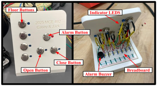
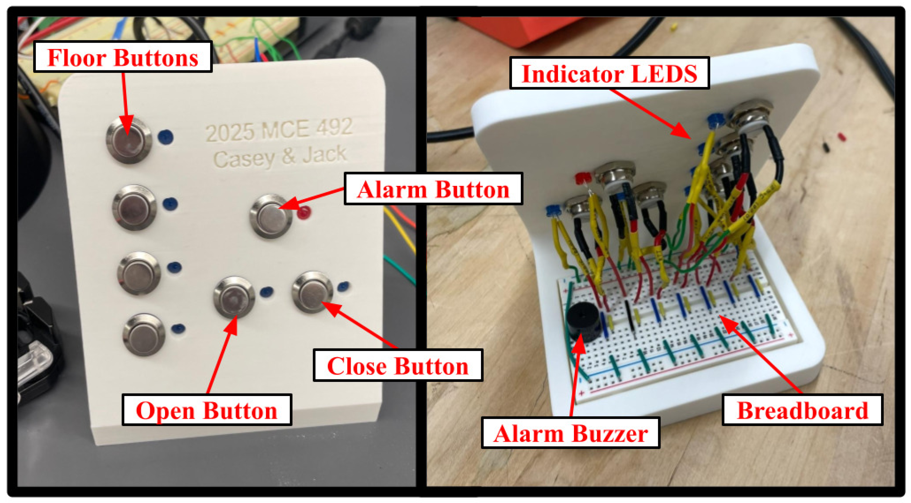
Aside from the outside button controls, elevators contain a panel on the inside that allows the rider to select their desired floor, open and close the carriage door, and trigger an emergency alarm. A model was designed to represent this panel, allowing for seven buttons with corresponding LEDs to be held, as well as a small breadboard that friction-fits into the base to allow for more efficient wire management.
Figure 1 and Figure 6 depict how the control buttons were arranged intuitively. Outside call buttons at each floor were positioned so that Up buttons were placed above Down buttons, similar to real elevator systems. Additionally, the inside button panel in Figure 6 was arranged with the Floor 4 button at the top of the column, and each lower floor button positioned correspondingly below it. Open and Close Door buttons were clearly labeled, and the Emergency Stop button was distinguished by a red LED placed next to it.
Figure 6.
Panel to represent the buttons on the inside of the elevator carriage with condensed wiring.
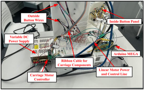
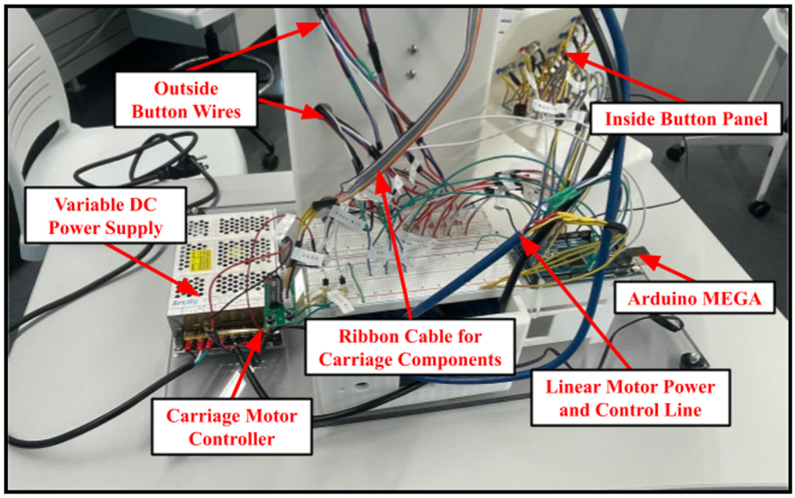
Adequate wire management is also integral for a complicated mechatronics system with moving components and the need to be used for a portable educational display. The elevator model necessitated multiple input voltages for various components, so a variable power supply was needed. For the carriage, a ribbon cable was chosen to provide a flexible solution to provide power to the door and safety sensor feedback. The use of the ribbon cable simplified wiring inside the frame and provided adequate slack for the moving components without the need for a cable drag chain. The various electronic components and controllers all have corresponding wires leading to a centralized circuit at the back of the tabletop model. Figure 7 shows how the wiring is labeled and organized to allow easier demonstration of the electronic components used in the model for student understanding.
Figure 7.
Condensed wiring of elevator components, including power and MCU.
2.2. Control Architecture
Using software is crucial in designing any mechatronic system, and programming the logic and control of the model elevator proved as much. The Arduino MEGA was chosen as the microcontroller for this model as it is widely available, open-source, and easily replicable for continued educational demonstrations. The Arduino controlled two main tasks: operating the carriage motion and the automatic door. The code for these tasks was structured using a task-state control software structure (refer to [17] (pp. 150–163) for more details). The coding for each of these tasks is detailed in the subsections below.
2.2.1. Elevator Motion Task
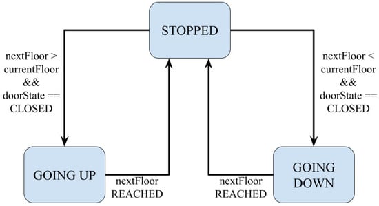
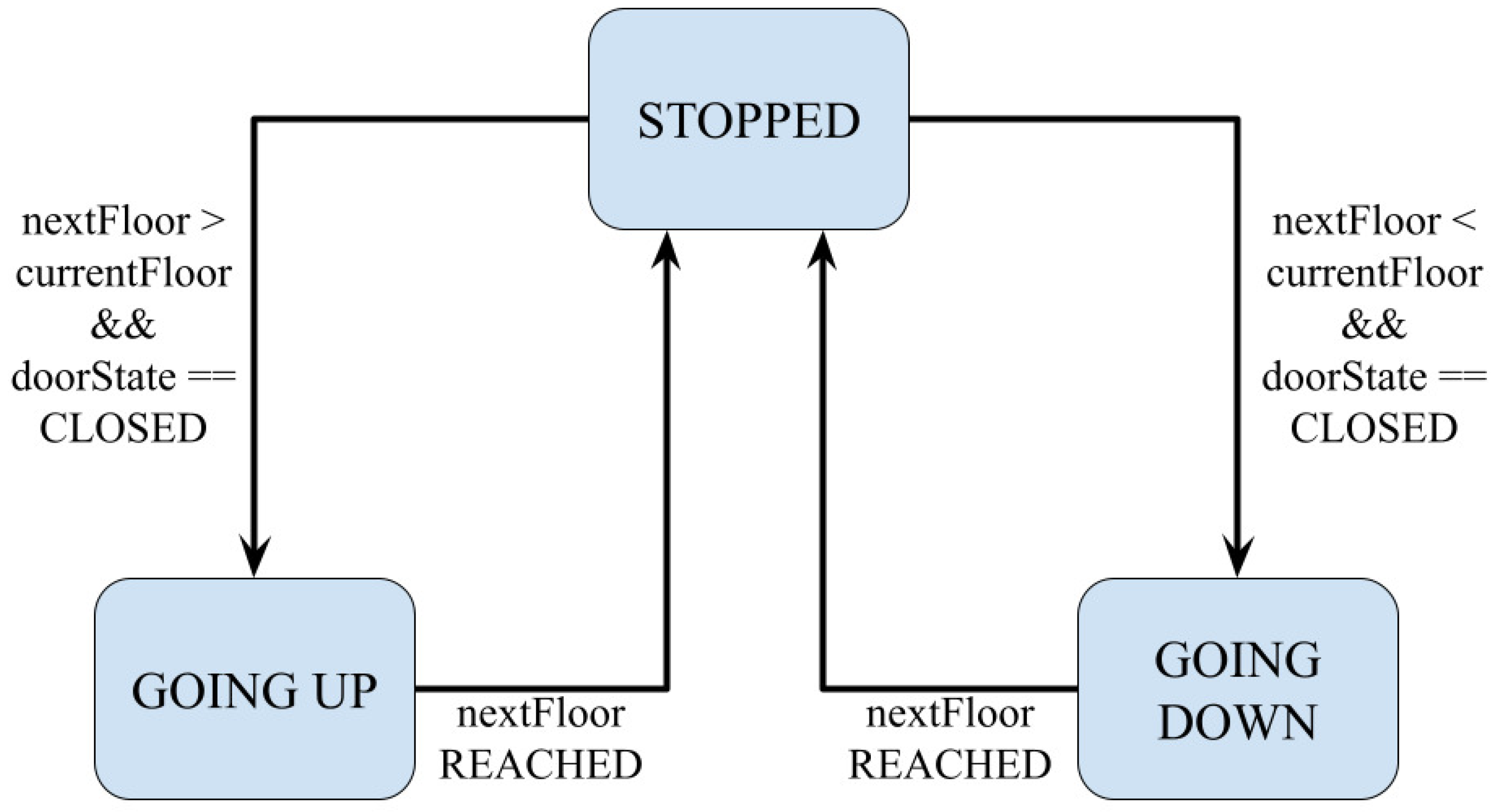
Figure 8 is the state transition diagram for the elevator motion task. The motion of the carriage has three states: STOPPED, GOING UP, and GOING DOWN. The majority of the routing logic occurs in the STOPPED state, which determines the value of nextFloor based on the request priority and travel efficiency. A simple heuristic model was developed to mirror this kind of logic, which has been shown in literature to be an efficient method for elevator routing [9]. Such an approach minimizes the total distance traveled and optimizes service time for users through grouping of requests traveling in the same direction and allowing for intermediate stops when appropriate (e.g., stopping at Floor 2 to pick up a passenger requesting Floor 3 while the elevator destination is Floor 4). Priority is always given to requests made inside the elevator car and then to requests matching the current or prioritized direction of travel.
Figure 8.
Elevator-motion state-transition diagram.
The approach can be broken down into three basic rules of decreasing priority to mimic the routing logic of commercial elevators: (1) service inside requests; (2) service requests that match the elevator’s current direction; (3) service intermediate-floor stops if they match the current travel direction and are achievable without excessive deceleration. To allow for intermediate stops, logic in the GOING UP and GOING DOWN states checks specific floors for new floor requests. Based on the value of nextFloor, this logic identifies intermediate floors that the elevator will pass and will stop at these floors if requests are made before the elevator is halfway to them. Determination of the half-floor distance is done through timekeeping, which was derived from floor-to-floor travel tests. The logic can then determine whether it is appropriate to reroute the elevator by changing the value of nextFloor.
2.2.2. Automatic Door Task
The model elevator replicates the safety features of a commercial elevator. This includes the carriage door remaining closed during travel and prevents the door from closing if an obstacle is detected.
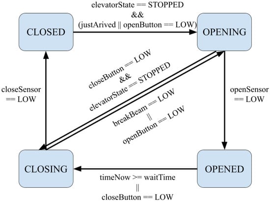
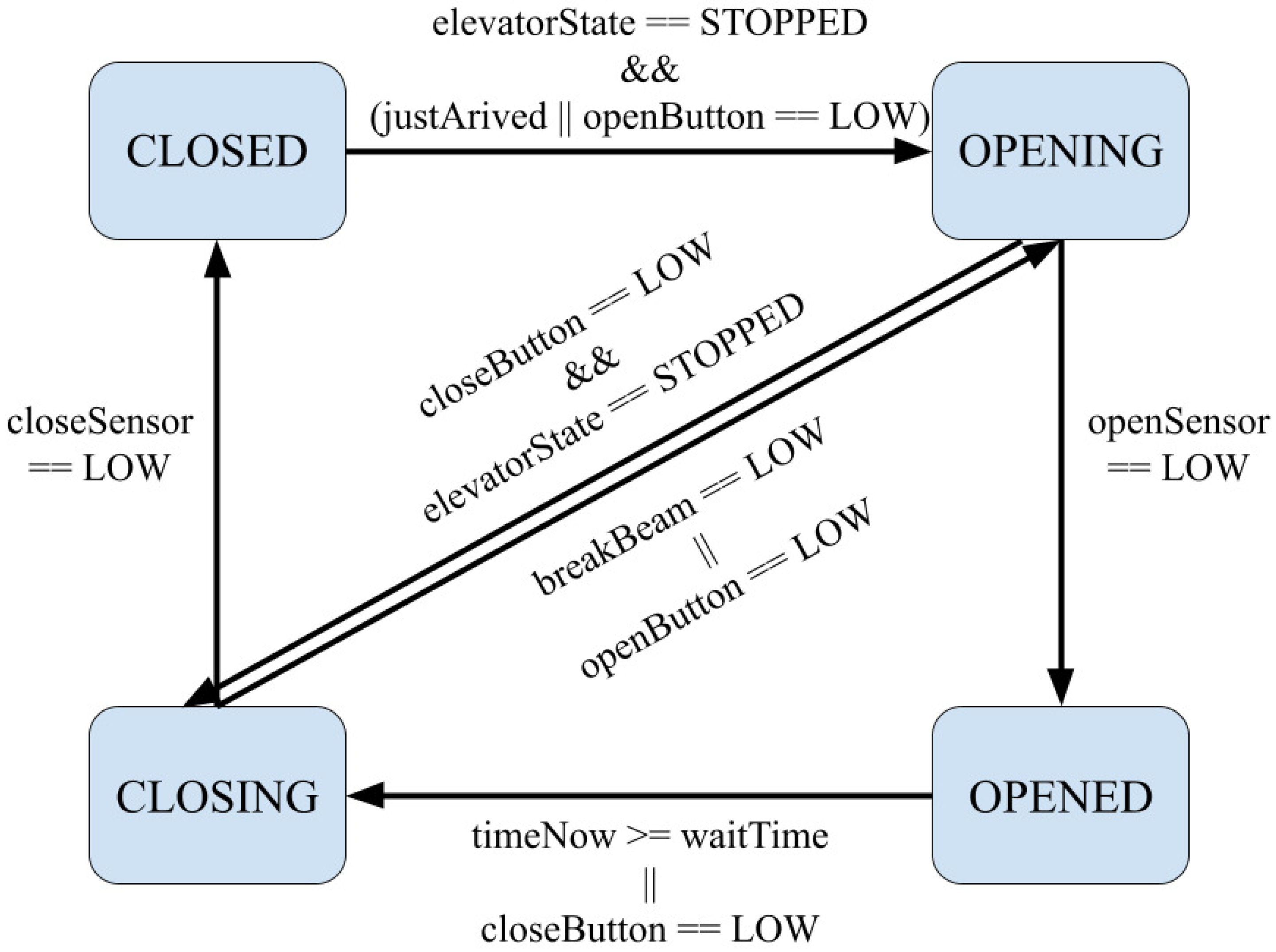
Figure 9 shows the state-transition diagram for the door task, which is only active if the elevator is in the STOPPED state. The door operates through four states: CLOSED → OPENING → OPENED → CLOSING → CLOSED. Hall-effect sensors on the carriage determine if the door is in the OPENED or CLOSED state. A break-beam automatically returns to the door to the OPENING state if an obstacle is detected. Non-blocking timing, implemented using Arduino’s millis() function, allows the door to transition to the closing state after a short delay without halting other operations. Buttons on the interior panel can override the timing, but safety features always remain active.
Figure 9.
Automatic-door state-transition diagram.
2.2.3. Control Program Operation
The main Arduino program for elevator control integrates the two sub-control tasks discussed previously in a coordinated, non-blocking loop. Upon startup, the elevator executes a homing sequence utilizing feedback from the Teknic motor and arrives at Floor 1, where it awaits user requests. While waiting, the elevator allows the door task to function.
Upon receiving floor requests, the program utilizes the heuristic approach described in Section 2.2.1 to determine the optimal route. It considers the elevator’s current location and evaluates multiple scenarios to determine which request would be most optimal to serve first, similar to model [9].
Before travel, the program ensures the door is in the CLOSED state. The elevator accelerates smoothly, continuing to accept outside requests during motion. It stops at intermediate floors en route to its destination if the acceptable conditions are met. Once the elevator reaches its destination floor, the indicator LED(s) turn off, and the door automatically opens. If no additional inputs are given, the elevator waits at the current floor for one minute. After this wait interval has elapsed, the elevator will return to Floor 1. Floor 1 is often the busiest floor in terms of frequency of requests made [18]; therefore, time is saved for passengers at this floor if the elevator returns to it when inactive.
The final elevator demo handles the two tasks of elevator motion and door automation in near parallel, while ensuring the system operates safely. Monitoring the many buttons inside and outside of the elevator determines which task to enter. The system focuses on transporting passengers quickly and efficiently by grouping and prioritizing requests in the same travel direction. The program operation replicates the behavior of a modern elevator in all key aspects, from carriage motion to door logic and safety, while remaining simple enough for educational use.
2.3. System Cost
A key feature of the developed product is the relatively low cost of this model elevator system. Table 1 lists the main components of this system and associated costs. The most expensive item is the motor ($399), followed by the ball screw stage ($138.80). The table lists only the main or unique items. Many of the components used in this project are commonly available in university mechatronics labs, which reduces the overall cost of the system. This includes wires, sensors, fasteners, 3D-printing material, etc.
Table 1.
Main components.
3. Results
3.1. Education Demonstration Use
The model elevator has been successfully used for demonstration in multiple settings. Informal feedback indicates that students and visitors engaged positively with the model. The elevator was demonstrated at outreach events for the University of Rhode Island, undergraduate mechatronics classes, and ASME student organization meetings. The visibility of the electronic and mechanical components allowed for a better understanding of the systems involved in elevator human-machine interfaces. The modular design and ability to remove the carriage allowed for further interaction with the dual-door system and the safety sensors during demonstrations.
3.2. Floor-to-Floor Motion Comparison
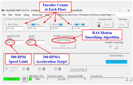
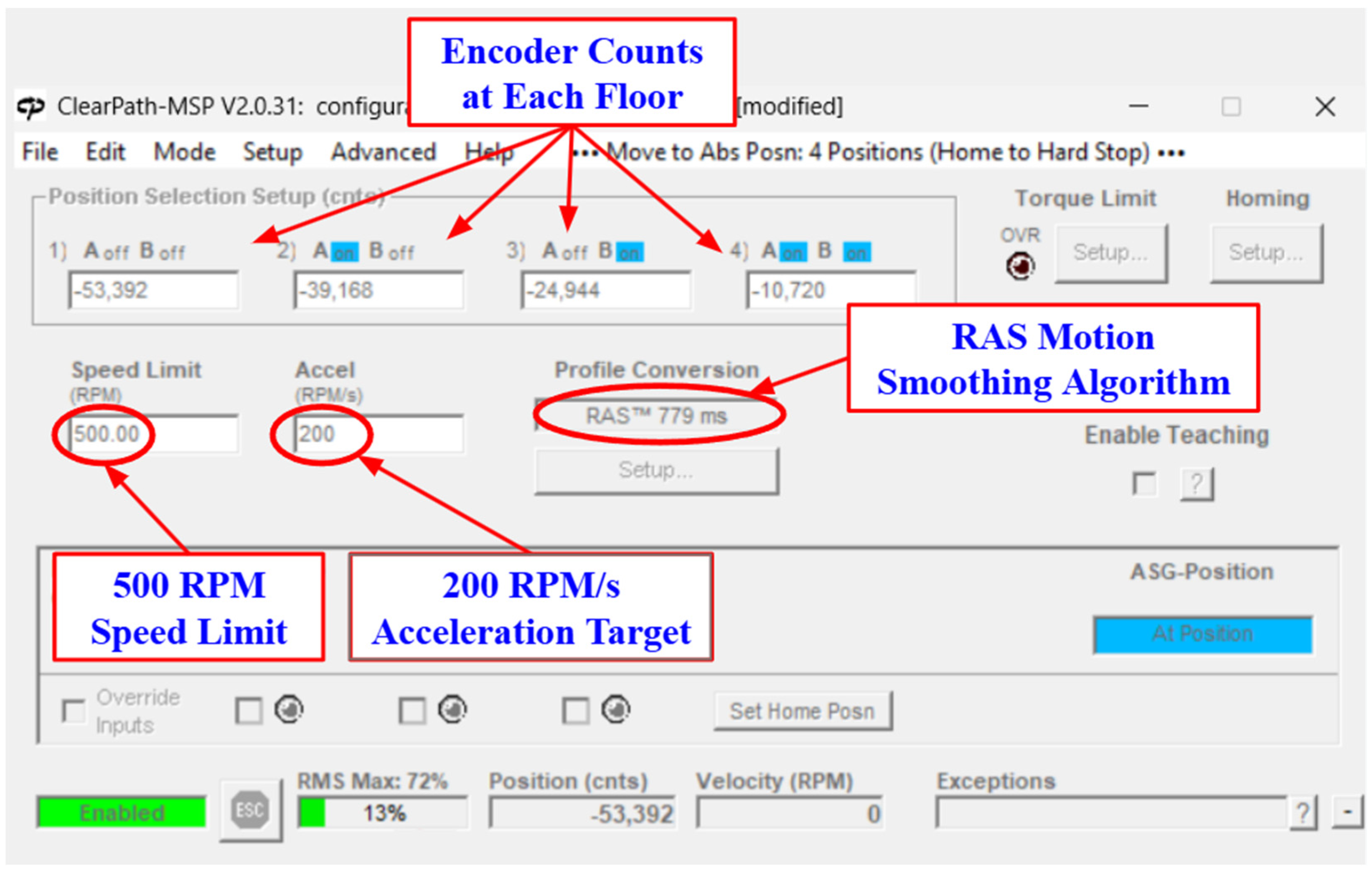
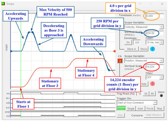
Velocity and trajectory profiles were used to demonstrate behavioral similarity between real-world elevator systems and the educational demonstration model. The Teknic motor used for vertical motion in the model was programmed with ClearPath MSP 2.0 (V2.0.31) software, the software provided by the integrated servo-motor manufacturer. The built-in trajectory generation functions enabled a range of user-defined velocity and acceleration targets, allowing for the motor to generate repeatable travel trajectories between floors representative of real-world systems. These settings are displayed in Figure 10, with encoder counts for each floor, and limits for peak velocity (in RPM) and target acceleration (in RPM/s). The motor controller employs a proprietary motion smoothing algorithm called Regressive Auto Spline (RAS), which, according to the manufacturer, goes beyond traditional S-curve or cosine smoothing by limiting both jerk and its derivative, resulting in more gradual motion profiles.
Figure 10.
ClearPath software user settings and RAS profile conversion.
To record the motion profiles, the ClearPath interface obtains readings directly from the motor. This was done through the “Scope” feature as described in the manual [19]. Motion profiles were measured during travel from floor 1 → 3 → 4 → 1. Both the measured velocity (in RPM) and the measured encoder position (in counts) are plotted in Figure 11. The blue recordings correspond to the angular velocity, and the red recordings correspond to the encoder position.
Figure 11.
ClearPath “Scope” interface with raw data from the model elevator motion.
With the very small travel distance from floor to floor in the model, only multi-floor travel showed sustained peak velocity in the ClearPath interface. To convert the ClearPath velocity (RPM) to vertical velocity v (m/s), Equation (1) is used, where L is the lead of the screw (0.005 m) and N is the motor RPM. Calculating yields a peak vertical velocity of ~0.04 m/s for the model.
V = L × N/60,
While the motor’s internal velocity profile provides a reliable estimate of carriage velocity, it does not capture backlash or mechanical compliance in the drive system, meaning transient dynamic effects may be slightly attenuated compared to true carriage motion. Nevertheless, this method was deemed most appropriate for recording the motion of the model due to sensor limitations at such a small scale, as further discussed in Section 3.3.
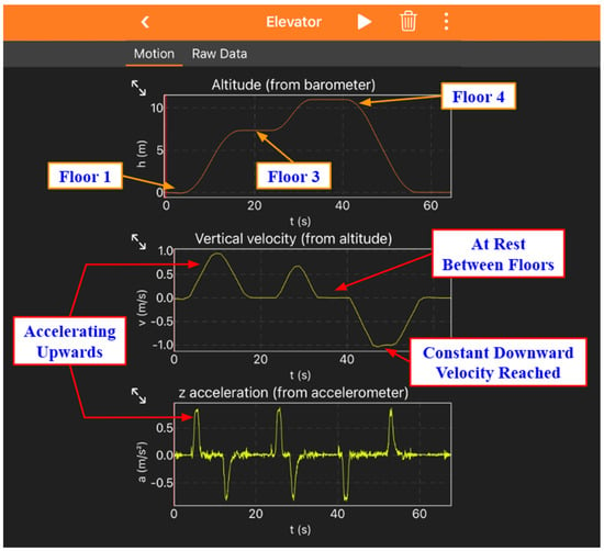
A four-floor elevator was used for real-world testing to compare with the model elevator’s motion. Data was recorded using the Phyphox mobile application, which uses sensors embedded in smartphones. The Phyphox app has a built-in elevator measurement system that includes altitude (from barometer), vertical velocity (derived from change in altitude), and z-acceleration (from accelerometer). The same trajectory of floor 1 → 3 → 4 → 1 was used for consistency, with the motion profiles displayed in Figure 12.
Figure 12.
Phyphox application interface and raw data output for real-world elevator motion.
The real-world elevator had peak vertical velocity ranging from ~0.6 m/s to 0.9 m/s to −1 m/s (from Figure 12), depending on the number of floors and direction of travel. Although the model elevator’s absolute velocity is significantly lower than the real-world system, scaling needs to be accounted for. Due to the model elevator’s compact size, which allowed mobility for classroom demonstrations, scaling must be taken into account when comparing velocities. To do this, the motion was normalized to floor-to-floor velocity.
To determine the average floor-to-floor velocity, the change in time from departure to arrival (when the velocity was non-zero in Figure 11 and Figure 12) was divided by the number of floors traversed for both systems. The motion from Floors 1–3 and 3–4 was analyzed for each system and then averaged. In both the model and the real-world elevator, if more floors are traversed, the floor-to-floor velocity increases. Despite the differences in scale, Figure 11 and Figure 12 show similar motion trends for position and velocity. In both cases, multi-floor travel exhibits sustained peak velocity while single-floor travel did not. This similarity supports the educational realism of the model. These results are further summarized in Table 2, where peak velocity in m/s and floor traversal rates are compared.
Table 2.
Floor-to-floor velocity comparisons.
3.3. Acceleration and Sensor Limitations
In a real-world elevator system, acceleration limits are critical for passenger comfort. The accelerations of the real-world elevator displayed through the Phyphox interface can be seen in Figure 12, with an average peak magnitude of ~0.8 m/s2. In the model, the acceleration limits were set to ensure visually smooth motion during demonstrations and mimic the travel experienced by passengers in real-world systems. The ClearPath software limits can be seen in Figure 10. Converting from RPM/s to m/s2 is done using Equation (2), where “a” is the linear acceleration, “L” is the lead, and “alpha” is the angular acceleration in RPM/s. This value was further validated using the slope of the velocity profile from Figure 11.
a = L × α/60,
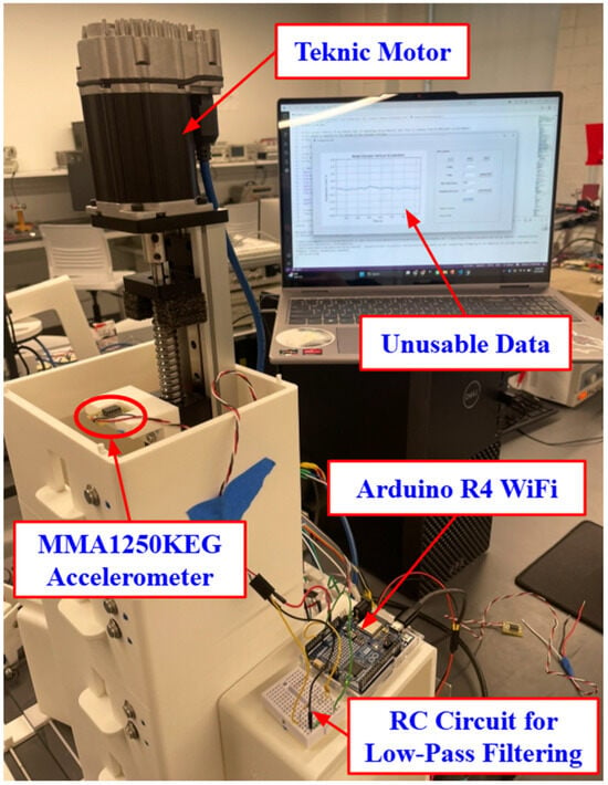
To physically measure acceleration in the model elevator, a low-cost external sensor was used. A 3D-printed sensor mount was created to replace the elevator carriage on the linear stage and ensure orthogonality of the accelerometer during testing. The sensor was connected to an Arduino using an RC filter circuit to reduce the voltage spikes, and a Python 3.14 script displayed live readings. As seen in Figure 13, the experimental setup and mapped output yielded results that were noisy.
Figure 13.
Experimental setup for acceleration measurements with Python GUI live display.
The noise observed in the external accelerometer signal was investigated and attributed primarily to a sensor resolution limitation rather than structural vibration. The carriage’s maximum linear acceleration, obtained by converting the motor’s maximum angular acceleration to the carriage’s linear acceleration, is approximately 0.017 m/s2. The accelerometer used (MMA1250KEG from NXP, Eindhoven, The Netherlands) has 400 mV/g sensitivity, as seen in the datasheet [20], and produces a corresponding output of ~0.68 mV, which is only approximately twice the voltage resolution of the 14-bit ADC on the Arduino R4 WiFi (5 V reference, ~0.305 mV/bit). At this signal-to-resolution ratio, the output appears as noise even after filtering. Regarding structural vibration, the primary sources are the motor and ball screw drive, along with minor frame flex during carriage motion. Given the low operating speeds and accelerations of the model, these vibrations were small in magnitude and did not measurably affect positioning accuracy or control response. Additionally, these vibrations did not affect the educational demonstration capabilities of the model.
3.4. Door Timing Comparison
As mentioned in previous sections, one of the novel components of the model elevator was the incorporation of the dual-door system. These response times for the model elevator door motion include small delays after button presses, and the time the door remains open before closing. The duration of the opening and closing sequences is dependent on the stepper motor used inside the carriage. Comparing these to a real-world elevator was done through physical testing, as well as comparing them with ADA guidelines.
Physical tests were performed with video analysis to determine how long the door took to open, how long it remained open when called, and how long it took to close. ADA specifications were pulled from the U.S. Access Board website [21] and include values for the time for the door to remain open. These values are different depending on whether the elevator is called from the outside or a floor is reached from the inside, as it is expected to take longer to enter the elevator than to leave. It gives additional time for anyone inside the elevator to exit if it is called from outside. For the model, the same remain-open timing was used for both inside and outside calls in the interest of simplicity; the model door still closely mirrors the behavior of that in a real-world elevator despite this discrepancy. Five trials were completed for each motion type, and these values are further summarized in Table 3.
Table 3.
Elevator door timing.
4. Discussion and Conclusions
This project focused on designing and fabricating a model elevator system to demonstrate mechatronics principles and provide a demonstration for engineering education. The design emphasized an intuitive user interface and realistic control logic that behaviorally mimics commercial elevator operation in terms of floor-to-floor travel rates and control logic rather than dynamic equivalence in a formal modeling sense. Using an Arduino MEGA, low-cost components, 3D-printed parts, and open-source software, the final four-story model effectively integrates mechanical, electrical, and software systems to perform coordinated, reliable motion control.
The motion control parameters were tested and compared with a real-world elevator to evaluate the model’s accuracy. The programmed order for operator request handling directly imitates real-world systems. Additionally, when the floor height discrepancies were normalized, the tabletop system demonstrated similar floor-to-floor travel rates to a real-world system.
Design decisions were made with manufacturability and reproducibility in mind. The plug-in structure and modular assembly are notable strengths of this work, as they lower the barrier for replication at other institutions and make the system adaptable to a range of instructional contexts from single-session demonstrations to semester-long projects. The visibility of components further highlights the multiple facets of mechatronic principles in a tangible way. The use of additive manufacturing allowed for rapid prototyping and iterative design but required validation through tolerance testing to ensure reliability.
Beyond demonstration, the tabletop elevator model provides valuable hands-on training in CAD design, motion control, programming, and system integration. Its modular structure makes it suitable for both semester-long group projects or smaller instructional modules that culminate in a final integrated system.
The primary software challenge was the optimization of the non-blocking code. Future work could incorporate “switch-case” logic that might streamline decision execution and improve the performance of the microcontroller.
The main mechanical challenge was with the interface between the inside and outside doors. Future refinements could address these issues by increasing motor torque, replacing the linear slide with a linkage mechanism, or reducing friction. Modifying the Hall-effect sensor placement and/or creating a more stable mount could help with misalignment and engagement issues caused by vibrations. A formal analysis of start-and-stop transient dynamics, frequency response, and acceleration measurement using appropriately selected sensors would strengthen the experimental validation of this work. Additionally, developing a simplified dynamic model of the system, such as a mass-spring-damper representation accounting for carriage mass, structural compliance, and actuator dynamics, and advanced motion control techniques such as feedforward compensation and input shaping, represents promising directions for future iterations.
Other areas for further research that build on this project involve developing a two-car system or modifying the vertical motion method by using the standard pulley-and-counterweight approach. These would enhance the educational value by mimicking real-world scenarios more accurately and introducing advanced control logic and design challenges.
Supplementary Materials
All of the CAD models required to reproduce this project, as well as demonstration videos of the model elevators features can be downloaded at: https://github.com/jouaneh/ModelElevator (accessed on 1 May 2026).
Author Contributions
Conceptualization, C.E., J.L. and M.K.J.; methodology, C.E., J.L. and M.K.J.; software, J.L. and C.E.; validation, C.E., J.L. and M.K.J.; formal analysis, C.E., J.L. and M.K.J.; investigation, C.E., J.L. and M.K.J.; resources, M.K.J.; data curation, C.E.; writing—original draft preparation, C.E. and J.L.; writing—review and editing, C.E., J.L. and M.K.J.; visualization, C.E. and J.L.; supervision, M.K.J.; project administration, M.K.J.; funding acquisition, M.K.J. All authors have read and agreed to the published version of the manuscript.
Funding
This research received no external funding.
Data Availability Statement
The original contributions presented in this study are included in the article/Supplementary Materials. Further inquiries can be directed to the corresponding author.
Acknowledgments
The authors would like to thank The University of Rhode Island for their contributions to this project. The mechatronics lab in the university provided many of the components for rapid electronic prototyping, 3D-printed services at the university were used, and support from the machine shop. During the programming phase of the project development, the authors used ChatGPT 4.1 generative AI to assist in programming and debugging state machine code for the door logic and motion tasks. The authors have reviewed and edited the output and take full responsibility for the content of this publication.
Conflicts of Interest
The authors declare no conflicts of interest.
Abbreviations
The following abbreviations are used in this manuscript:
| ADA | Americans with Disabilities Act |
| AM | Additive Manufacturing |
| ASME | American Society of Mechanical Engineers |
| FDM | Fused Deposition Modeling |
| HLFB | High-Level Feedback |
| MCU | Microcontroller Unit |
| LED | Light-Emitting Diode |
| PLA | Polylactic Acid |
| RC | Resistor Capacitor (circuit) |
References
- Al-Kodmany, K. Tall Buildings and Elevators: A Review of Recent Technological Advances. Buildings 2015, 5, 1070–1104. [Google Scholar] [CrossRef] [Scilit]
- Nichols, S.R. The evolution of elevators: Physical-human interface, digital interaction, and megatall buildings. In Frontiers of Engineering: Reports on Leading-Edge Engineering from the 2017 Symposium; National Academies Press: Washington, DC, USA, 2018; pp. 85–97. [Google Scholar] [CrossRef] [Scilit]
- Qin, Z.; Wu, Y.; Cong, J.; Lyu, S.K. Mechanism Design and Experimental Verification of Novel Automatic Balance Equipment for a Rope-Type Elevator. Machines 2022, 10, 1180. [Google Scholar] [CrossRef] [Scilit]
- Shi, J.; Zhang, W.; Wu, C. Vertical vibration modeling for 2:1-roping traction elevator system. J. Vibroeng. 2022, 24, 290–304. [Google Scholar] [CrossRef] [Scilit]
- Jackvony, B.; Jouaneh, M. Building an Educational Automated Mechatronics-Based Sorting System. Automation 2024, 5, 297–309. [Google Scholar] [CrossRef] [Scilit]
- Codourey, A.; Perroud, S.; Mussard, Y. Miniature Reconfigurable Assembly Line for Small Products. Precis. Assem. Technol. Mini Micro Prod. 2006, 198, 193–200. [Google Scholar] [CrossRef] [Scilit]
- Scheffe, P.; Maczijewski, J.; Kloock, M.; Kampmann, A.; Derks, A.; Kowalewski, S.; Alrifaee, B. Networked and Autonomous Model-scale Vehicles for Experiments in Research and Education. IFAC-PapersOnLine 2020, 53, 17332–17337. [Google Scholar] [CrossRef] [Scilit]
- Stein, A.; Parcic, T.; Singh, T. From playground swings to sway control of cranes: An active pendulum experiment. Int. J. Mech. Eng. Educ. 2023, 51, 139–154. [Google Scholar] [CrossRef] [Scilit]
- Gharbi, A. Exploring Heuristic and Optimization Approaches for Elevator Group Control Systems. Appl. Sci. 2024, 14, 995. [Google Scholar] [CrossRef] [Scilit]
- Ahmed, S.; Shekha, M.; Skran, S.; Bassyouny, A. Investigation of optimization techniques on the elevator dispatching problem. In Proceedings of the 9th International Conference on Computer Networks & Communications (CCNET 2022), Dubai, United Arab Emirates, 19–20 February 2022; Volume 12, pp. 37–49. [Google Scholar] [CrossRef] [Scilit]
- Lu, Y.; Li, J. Research on group control elevator scheduling method based on fuzzy control algorithm. Int. Conf. Math. Model. Comput. Sci. (MMCS2022) 2023, 12625, 96. [Google Scholar] [CrossRef] [Scilit]
- Cao, Z.; Guo, R.; Tuguinay, C.M.; Pock, M.; Gao, J.; Wang, Z. Application of deep Q learning with simulation results for elevator optimization. arXiv 2022. [Google Scholar] [CrossRef] [Scilit]
- Loker, D. Elevator control system project. In Proceedings of the ASEE Annual Conference and Exposition, Conference Proceedings, Louisville, KY, USA, 20–23 June 2010; pp. 15.450.1–15.450.11. [Google Scholar] [CrossRef] [Scilit]
- Sanfilippo, F.; Økter, M.; Eie, T.; Ottestad, M. Teaching motion control in mechatronics education using an open framework based on the elevator model. Machines 2022, 10, 945. [Google Scholar] [CrossRef] [Scilit]
- Lee, S. Development of a four-story elevator system for teaching motion control concept with programmable logic controller. In Proceedings of the 2010 Annual Conference & Exposition, Louisville, KY, USA, 20–23 June 2010. [Google Scholar] [CrossRef] [Scilit]
- Grgić, I.; Karakašić, M.; Glavaš, H.; Konjatić, P. Accuracy of FDM PLA Polymer 3D Printing Technology Based on Tolerance Fields. Processes 2023, 11, 2810. [Google Scholar] [CrossRef] [Scilit]
- Jouaneh, M. Fundamentals of Mechatronics, 2nd ed.; Cengage Learning: Mason, OH, USA, 2025. [Google Scholar]
- Zhang, J.; Zong, Q. Energy-saving scheduling optimization under up-peak traffic for group elevator system in building. Energy Build. 2013, 66, 495–504. [Google Scholar] [CrossRef] [Scilit]
- Teknic, Inc. ClearPath User Manual, Rev. 3.27; Teknic, Inc.: Victor, NY, USA, 2025; Available online: https://www.teknic.com/files/downloads/clearpath_user_manual.pdf (accessed on 31 March 2026).
- NXP Semiconductors. MMA1250KEG: ±5 g, 5.0 V Analog Accelerometer Data Sheet; NXP Semiconductors: Eindhoven, The Netherlands, 2013; Available online: https://www.nxp.com/docs/en/data-sheet/MMA1250KEG.pdf (accessed on 15 May 2026).
- United States Access Board. Chapter 4: Elevators and Platform Lifts. Available online: https://www.access-board.gov/ada/guides/chapter-4-elevators-and-platform-lifts/ (accessed on 31 March 2026).

Disclaimer/Publisher’s Note: The statements, opinions and data contained in all publications are solely those of the individual author(s) and contributor(s) and not of MDPI and/or the editor(s). MDPI and/or the editor(s) disclaim responsibility for any injury to people or property resulting from any ideas, methods, instructions or products referred to in the content. |
© 2026 by the authors. Licensee MDPI, Basel, Switzerland. This article is an open access article distributed under the terms and conditions of the Creative Commons Attribution (CC BY) license.