


Abstract
The purpose of this study is to develop a robot that reduces labor and automates cable-laying work at construction sites. The robot should have the ability to pull lead cables over cable racks and ceiling spaces. Therefore, we propose a reconfigured active-cord-mechanism robot based on the RSAW mechanism that can move in both environments by maintaining continuous traveling wave propagation across multiple units connected through joints. A prototype robot was first constructed to verify the applicability of the RSAW mechanism to cable-laying environments. However, the discontinuity of the traveling wave at the joint connections prevented the prototype from traversing ceiling spaces. Based on this finding, a new robot was developed with a configuration that ensures continuous wave propagation across the joints through mechanical design and phase synchronization control. As a result, the new robot enhances propulsion speed and cable traction. Additionally, the robot can move over ceiling joint receivers that exist in ceiling spaces. Comparative analysis with previous prototype robots and a snake-like robot highlights this robot’s advantages, including reduced motor count, autonomous operation with mounted power and control units, and superior turning capabilities.
1. Introduction
Cable-laying in ceiling spaces and on cable racks is one of the inevitable tasks required in electrical installations. It is essential to establish power and communication for equipment installed in ceilings. Similar to other electrical work, the challenge of increasing work efficiency while ensuring safety in cable-laying operations is important. In general cable-laying work, a thin priming wire called a lead cable is first laid in the target space, and then a main cable, which is tied to the lead cable, is laid by pulling the lead cable. In the process, skilled workers manually thread the lead cable using a stepladder or an elevated work vehicle. This work is hazardous because it is performed at high elevations, in dark places, and in confined spaces.
Another important issue is the declining number and rising average age of engineers responsible for cable-laying, which cannot be ignored. In Japan, the number of skilled workers in the construction industry decreased from 4.55 million in 1997 to 3.31 million in 2010 and 3.02 million in 2022. The percentage of construction workers aged 55 or older was about 24% in 1997, and this increased to 36% in 2022. Conversely, the percentage of workers aged 29 or younger decreased from approximately 22% in 1997 to approximately 12% in 2022 [1].
This background has motivated researchers to develop robots that can save labor in cable-laying work. For automating this cable-laying work, robots must be able to travel on ladder-like scaffolds, namely cable racks, and overcome obstacles found in ceiling spaces. In previous studies, cable-laying robots specialized for ceiling spaces or cable racks have been developed. One of them, which is specialized for cable-laying work in ceiling spaces, has already reached the level of practical use and has been used in the field [2]. However, due to space limitations in ceiling spaces, the robot is designed with a body length of 30 cm and is unsuitable for cable-laying on cable racks where the distance between sub-beams is generally 30 cm or longer. In addition, the cable-laying robot specialized for cable racks does not support laying cables in ceiling spaces due to its structure [3]. For these reasons, a robot that can travel in both environments is desirable for cable-laying work.
Robots for cable-laying tasks are required to have the ability to move through narrow spaces and on cable racks and ladder-like structures. In addition, cable-laying tasks must be performed while moving in an environment where many obstacles exist in the ceiling space, such as suspension bolts, supports for the ceiling, field edges, their edge supports, fire detectors, lighting fixtures, etc. Researchers have been working on developing robots that can operate in such restrictive environments [4,5,6]. Among them, snake-like robots are capable of propulsion in narrow spaces and exhibit high propulsion capability even on uneven terrain [7,8]. Furthermore, in some studies, snake-like robots have been used for inspection and investigation in complex environments such as pipelines, disaster surveys, and light work tasks [9,10,11]. Snake-like robots, utilizing their slender body shape and redundant degrees of freedom, can adapt and move through given environments [12,13,14,15]. For example, snake-like robots can move on sandy surfaces [16], sandy substances [17], underwater [18,19,20], and over obstacles [21,22] and can climb ladders [23], stairs [24,25], and ropes [26]. Related studies have shown that snake-like robots exhibit high propulsion capabilities in narrow spaces, uneven terrain, and environments with spaced cylindrical obstacles [27,28]. The environments targeted by these related studies are similar to cable-laying environments. Therefore, snake-like robots have attracted attention as a promising solution for cable-laying tasks.
Our research group has been focusing on active-cord-mechanism robots, which demonstrate high propulsion capabilities even in narrow or uneven terrain. Yuki, Hayato et al. focused on a snake-like robot, which generates a vertical traveling wave by sequentially coordinating multiple motors placed at each joint, and realized forward and backward movement in both cable racks and ceiling spaces. However, the robot is not able to change its direction, nor is it able to avoid obstacles [29]. In addition, from the robot’s design point of view, there are several issues; for example, its moving speed cannot be increased due to the performance limitations of the servo motors placed at each joint of the robot. Also, the robot needs to be lightweight from the viewpoint of structural load, such as the durability of the ceiling board material [30]. For cable-laying automation, external wired power supply and control signal transmission must be eliminated; that is, the robot should be battery-driven and have an on-board controller so that it does not need to be wired from the outside to supply power or send control signals.
To solve these problems, this study aims to design a robot configuration for a single-motor-actuated system capable of cable-laying tasks by pulling a lightweight lead cable in both cable racks and ceiling spaces, where continuous traveling wave propagation must be maintained across discrete support structures and joints. In a previous study on single-motor-driven robots, a reconfigurable single-actuator-wave (RSAW) robot capable of climbing obstacles was proposed [31,32], in which the locomotion mechanism, including the relationship between wave parameters and propulsion characteristics as well as contact behavior during motion, was analyzed and experimentally validated. This robot generates traveling waves using a special mechanism, enabling it to navigate steps and uneven terrains. Compared to snake-like robots driven by multiple joint motors, the RSAW mechanism offers advantages in terms of reduced motor count and lighter weight while achieving comparable propulsion performance. By preparing several RSAW units and reconfiguring their combinations according to the application, an RSAW-based robot can meet the mobility requirements for cable-laying environments. However, when multiple units are connected through joints, maintaining continuity of the traveling wave across those joints becomes a critical design challenge.
Based on this background, the purpose of this study is to develop a reconfigured active-cord-mechanism robot based on the single-motor-actuated RSAW mechanism for cable-laying applications in ceiling spaces and on cable racks. In such environments, multiple RSAW units must be connected through joints and operate on discrete support structures, where discontinuities in the traveling wave may occur at the connection points. Therefore, this study focuses on the design of the robot’s configuration and the selection of design parameters that enable continuous traveling wave propagation across the joints. An experimental robot is developed by reconfiguring the combination of RSAW units, and phase synchronization among the units is introduced to maintain wave continuity. Using this experimental robot, fundamental motions, including forward and backward movement, turning on a flat surface, and traversal over obstacles, are demonstrated, and the feasibility of the proposed design for practical cable-laying tasks is verified.
2. Environments
This section describes the experimental environments—a cable rack and a mock ceiling space—where the robot developed in this study is intended to move.
2.1. Cable Rack
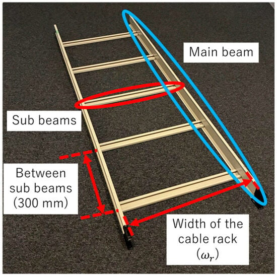
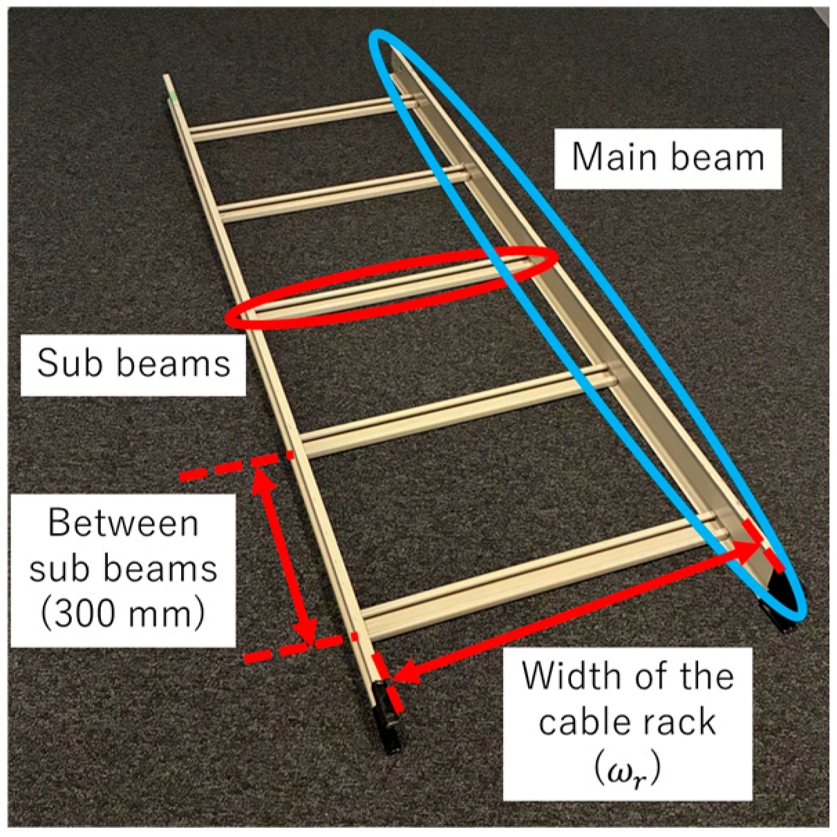
Cable racks are commonly used in buildings and various other structures and facilities. Cable-laying robots inherently need the ability to move on these cable racks. To enhance versatility, this study focuses on cable racks manufactured by NEGUROSU DENKO (Tokyo, Japan), which holds a high market share (approximately 70–80%) in Japan. The specifications for NEGUROSU DENKO’s standard straight cable rack—the SR series—are shown in Figure 1. A typical cable rack consists of a main beam and sub-beams. The parameters of the cable rack selected as the experimental environment in this study are as follows: the sub-beam width is 40 mm, the interval between sub-beams is 300 mm, and the main beam length is 3000 mm. The width of the cable rack is determined by an equation based on technical guidelines for electrical equipment planning and design from the Ministry of Agriculture, Forestry, and Fisheries. Here, the width of the cable rack [mm] and the outer diameter of each cable [mm] are used. is calculated by (1) [33].
Figure 1.
Cable rack used in this study.
Typically, is chosen between 200 mm and 1000 mm, considering the weight. In this study, a median width of 600 mm is selected for the cable rack.
2.2. Ceiling Space
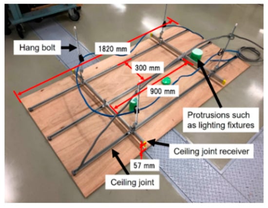
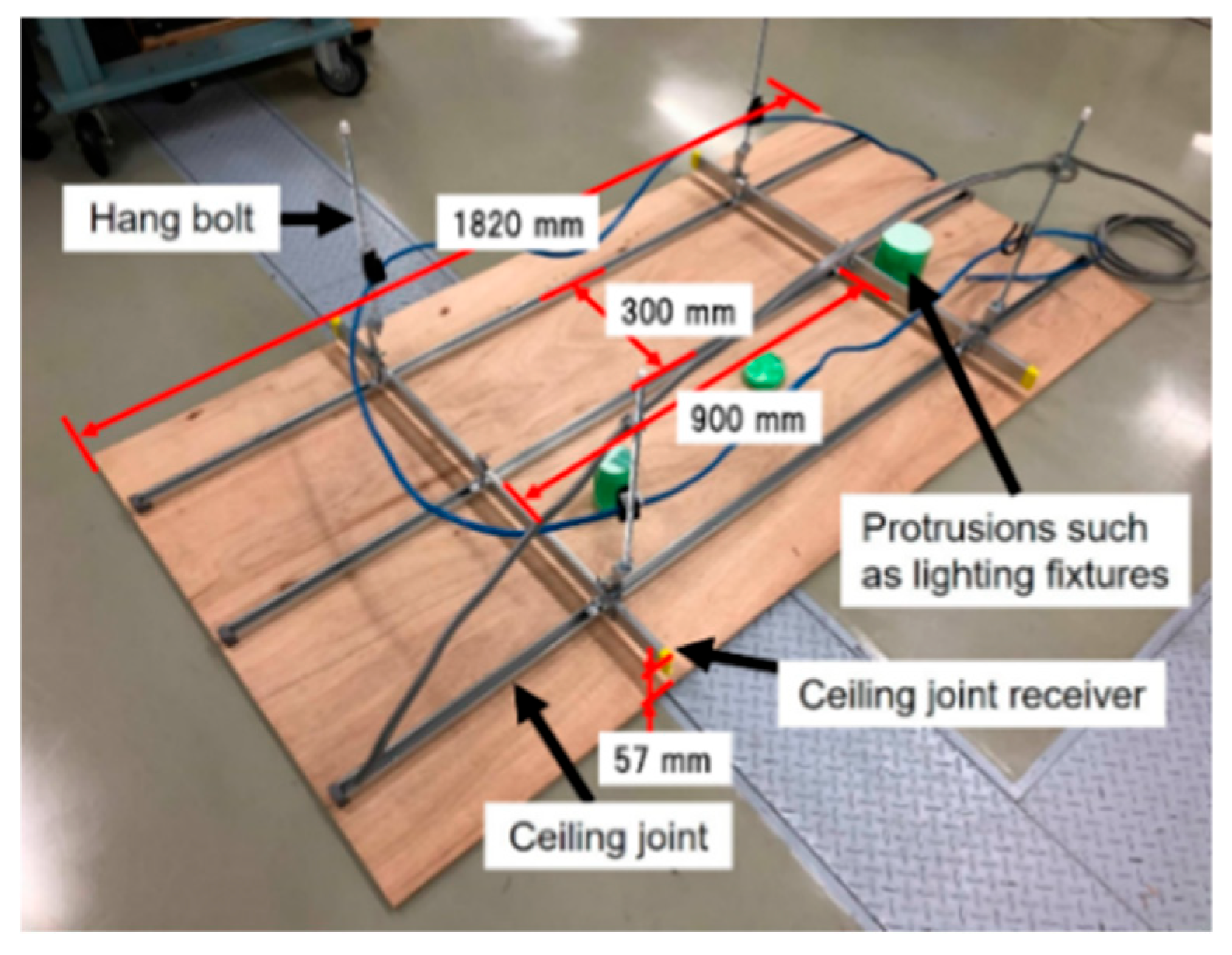
A mock ceiling space shown in Figure 2 is used as an experimental environment for cable-laying in real ceiling spaces. The mock ceiling space is constructed with hang bolts, ceiling joints, and ceiling joint receivers, with plywood used as the ceiling panel instead of gypsum board. The long side of the mock ceiling space is 1820 mm, and the height from the ceiling panel to the top of the ceiling joint receiver is 57 mm. The distance between the ceiling joint receivers is approximately 900 mm, and the distance between the ceiling joints is approximately 300 mm. These parameters are typically specified in [34].
Figure 2.
Mock ceiling space.
These structural features of both environments impose specific constraints on the robot design, particularly regarding body length, wave parameters, and the ability to traverse discrete support structures, as discussed in the following sections.
3. Review of the Traveling Mechanism of the RSAW Unit for the Design of a Cable-Laying Robot
As described in Section 2, in environments such as cable racks and ceiling spaces, the robot is required to move while pulling a lightweight lead cable. In such environments, the design must take into account the supporting structures of the ceiling panels and the sub-beams of the cable racks.
In the RSAW mechanism proposed by Danial et al., the detailed principles of traveling wave generation and locomotion have been clarified. In this study, based on these principles, it is necessary to consider a design that enables propulsion using the RSAW mechanism under the above environmental conditions.
Therefore, based on the kinematic and mechanical analyses presented in [31], the parts corresponding to the design parameters required in this study are briefly summarized. Parameters such as amplitude, wavelength, and angular frequency can be considered as design parameters of the cable-laying robot, since they characterize the fundamental traveling wave of the RSAW unit.
A typical active-cord-mechanism robot based on the RSAW unit achieves movement by generating traveling waves. This section describes the mechanism for generating traveling waves and outlines a conceptual approach for its implementation. The parameters of the traveling wave are listed in Table 1. The model of a traveling wave at position and time is expressed in (2).
Table 1.
Parameter definition.
A curve with an axis along the x-axis is defined by parametric equations in terms of the independent parameter , as shown in (3)–(5).
When a spatial helix rotates counterclockwise around the x-axis at a constant angular velocity , it is represented by (6) and (7).
The independent parameter is given in (8).
The time it takes for the spatial helix to make one rotation is expressed in (9).
The traveling speed of the wave is expressed in (10), which characterizes the propagation of the traveling wave. The actual locomotion speed of the robot is determined by the interaction with the surface, although it depends on the wave propagation speed as discussed in [31].
The equation obtained by substituting with is shown in (11).
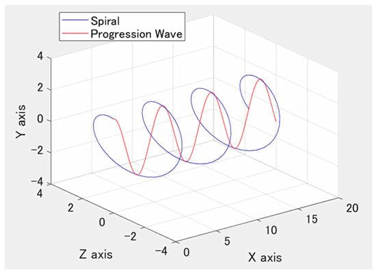
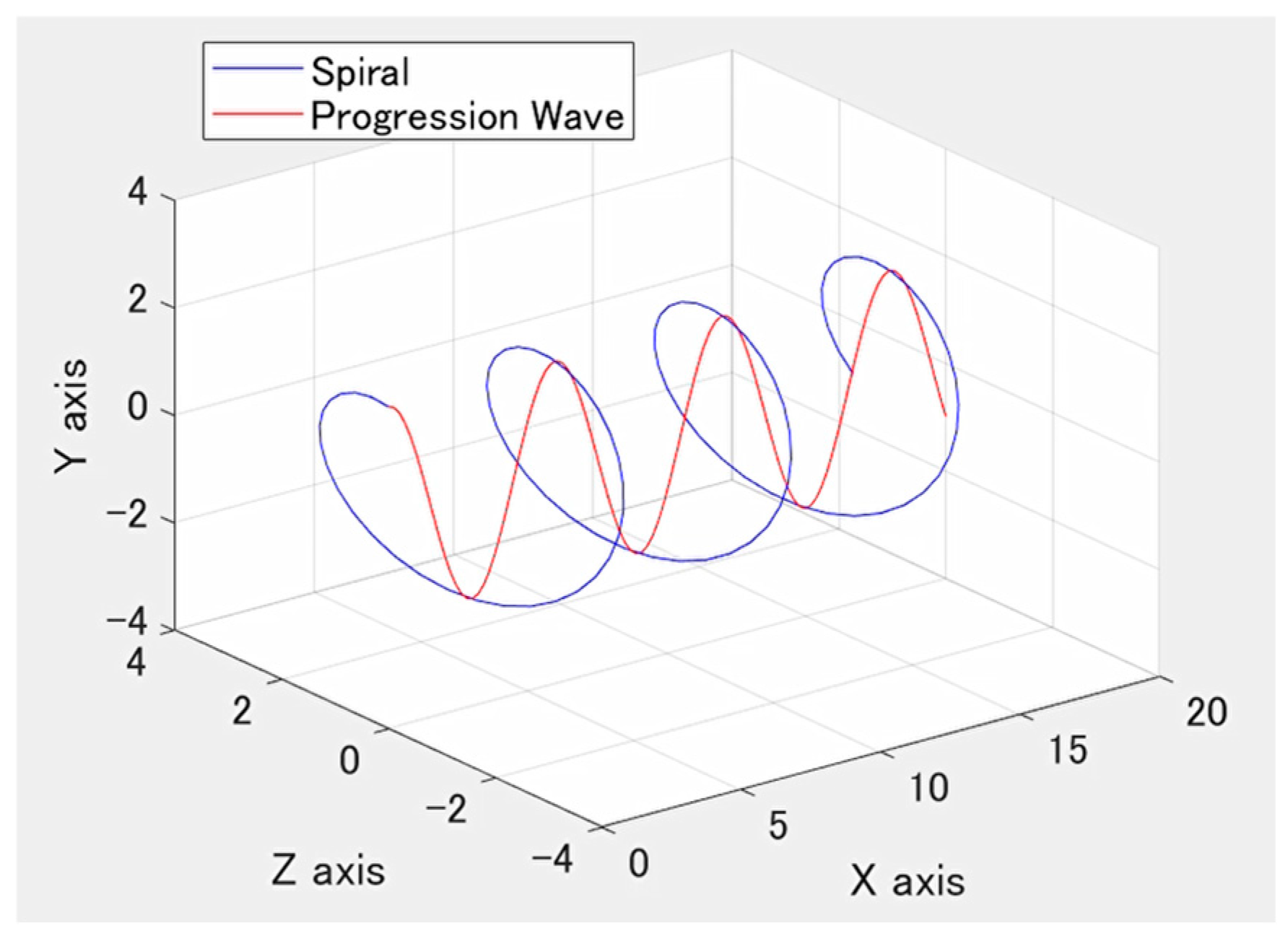
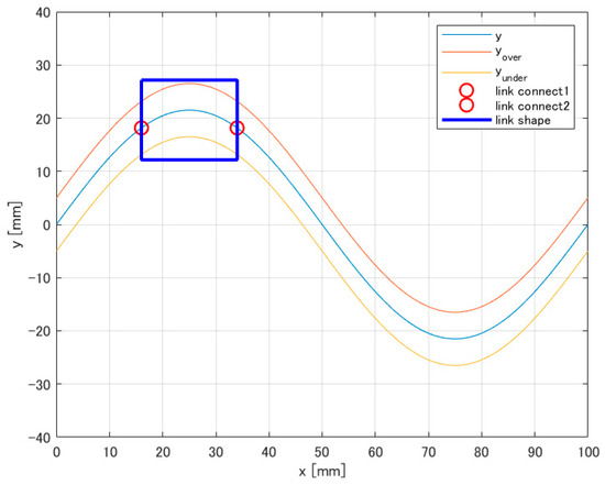
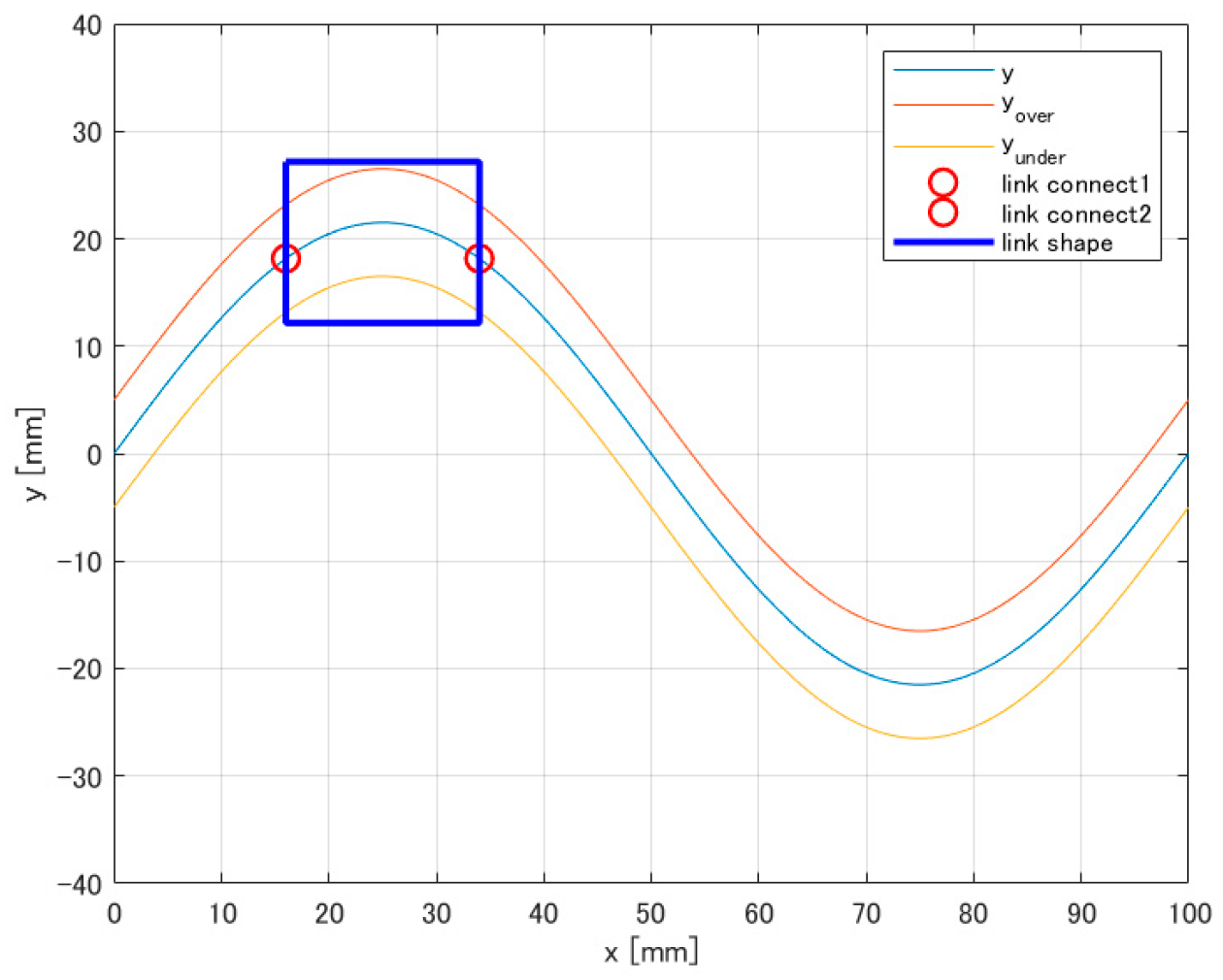
From these equations, when a helix with a radius of 1 rotates around the x-axis over time t, its projection onto the x − y plane forms a traveling sine wave, as illustrated in Figure 3. The radius and wavelength of the helix correspond to the amplitude and wavelength of the sine wave, respectively. The angular velocity of the helix is also related to the traveling speed of the sine wave. Therefore, these relationships can be used as design parameters of the robot characterized by the generated traveling waves obtained by projecting the rotation of the helix onto the two-dimensional vertical plane.
Figure 3.
Projection of the helix onto the vertical plane generates a traveling wave.
These wave parameters serve as the basis for designing RSAW units tailored to the constraints of cable-laying environments described in Section 2, as detailed in the following section.
4. Development of the RSAW Unit
This section describes the development of the RSAW unit for cable-laying applications. The design of the RSAW unit involves two key aspects: the helix design, which determines the traveling wave characteristics based on the wave parameters described in Section 3, and the attachment design, which realizes the helix motion as propulsion through contact with the surface. Both must be designed in accordance with the structural constraints of the cable-laying environments described in Section 2, namely the sub-beam spacing of cable racks and the ceiling joint receivers in ceiling spaces.
As an initial step, a preliminary RSAW unit was constructed based on the designs presented in [31] and tested in the cable-laying environments. Based on the findings, both the helix and the attachment were redesigned to meet the environmental constraints, resulting in the environment-specific RSAW unit described in Section 4.2.
4.1. Preliminary RSAW Unit
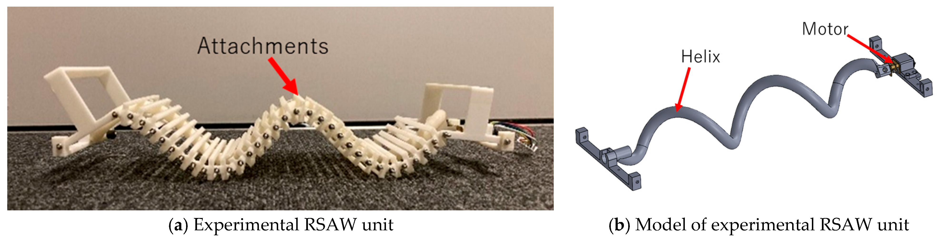
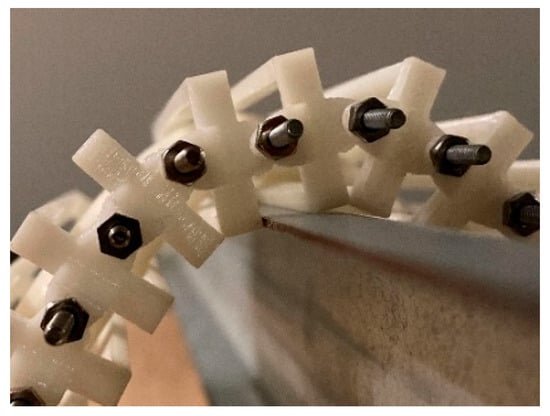
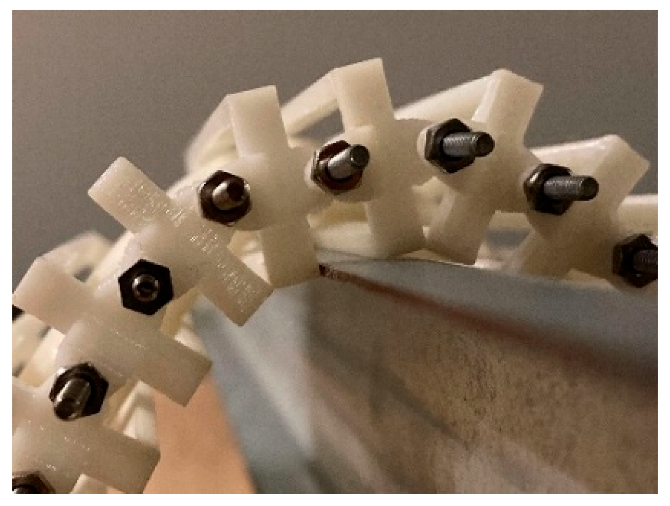
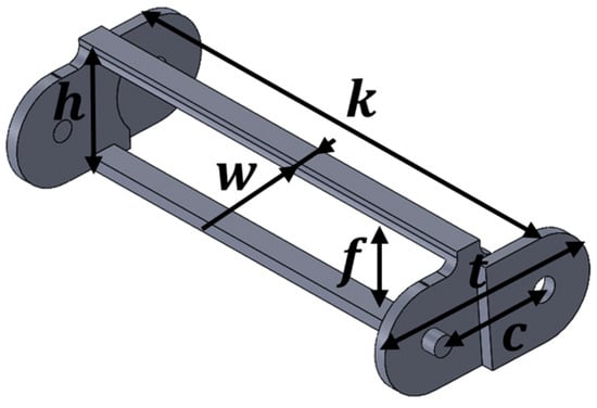
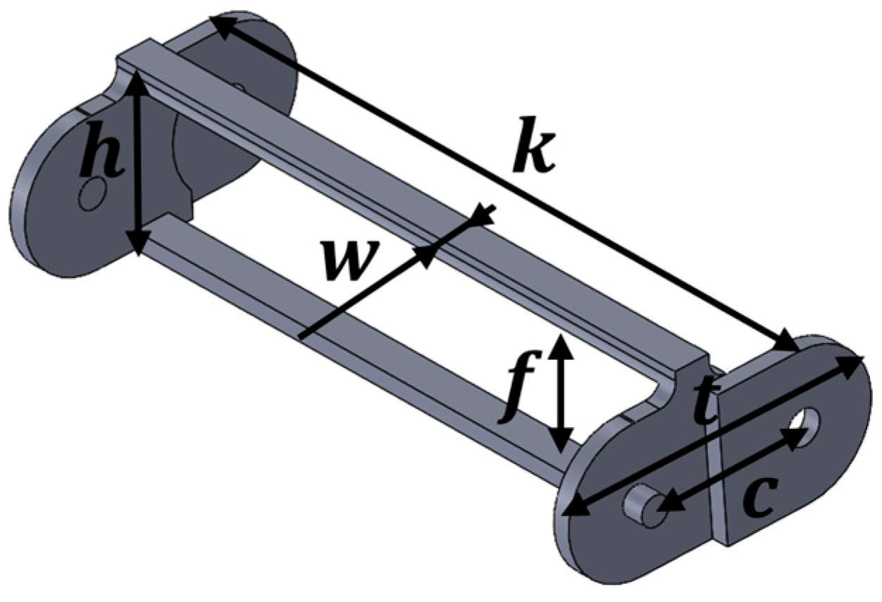
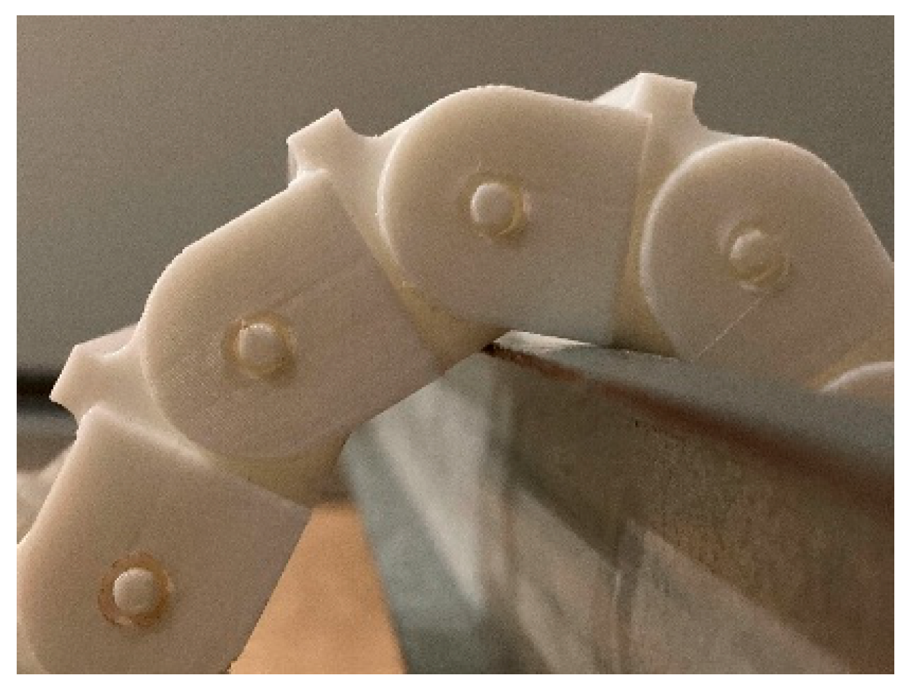
To evaluate the applicability of the RSAW mechanism to cable-laying environments, a preliminary RSAW unit was constructed following the helix and attachment designs presented in [31], as shown in Figure 4a. The mechanism involves an attachment that constrains the movement of the helix to two dimensions, effectively covering the helix. Additionally, this attachment increases the contact area with the ground. The attachment has the same structure as a cable carrier [35]. The helix is controlled by an encoder-equipped gear motor attached to its end, as shown in Figure 4b. However, when the RSAW unit was placed on the ceiling joint receiver, the gaps between adjacent attachments caused this preliminary unit to become stuck, preventing traversal, as shown in Figure 5. This indicated that both the helix and the attachment required redesign to suit cable-laying environments.
Figure 4.
Experimental RSAW unit.
Figure 5.
Experimental RSAW unit placed on a ceiling joint receiver.
4.2. Environment-Specific RSAW Unit
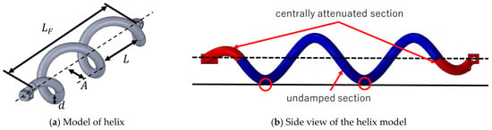
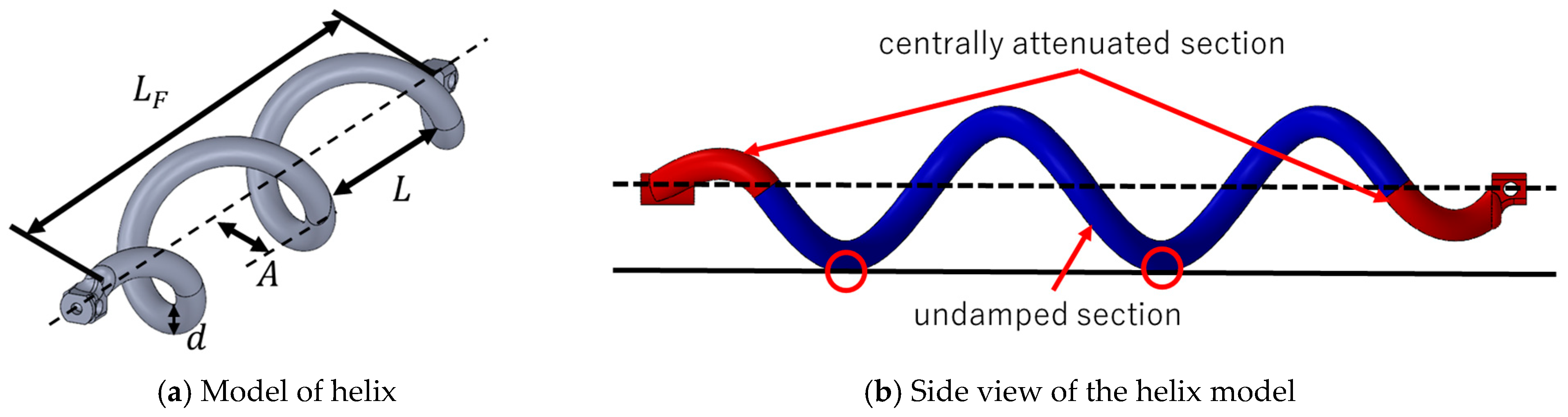
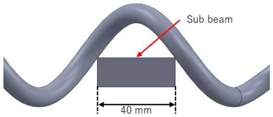
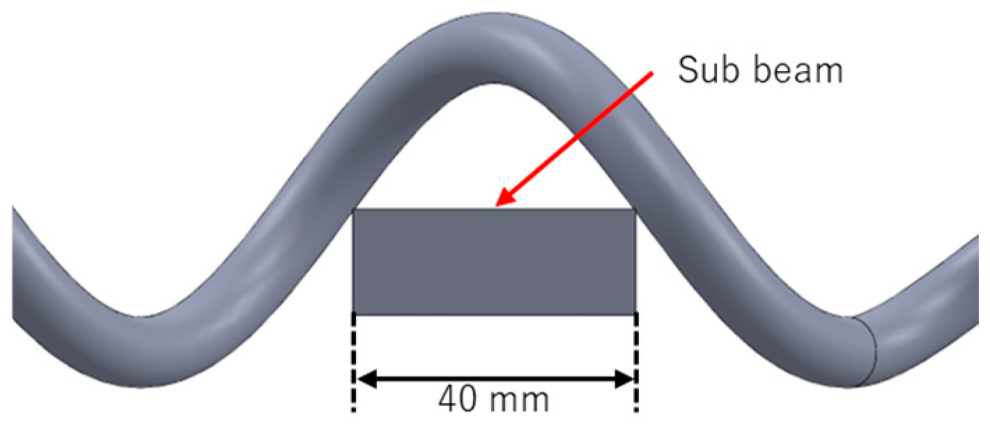
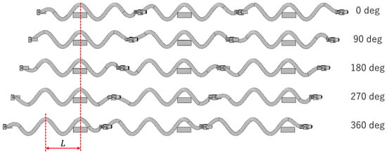
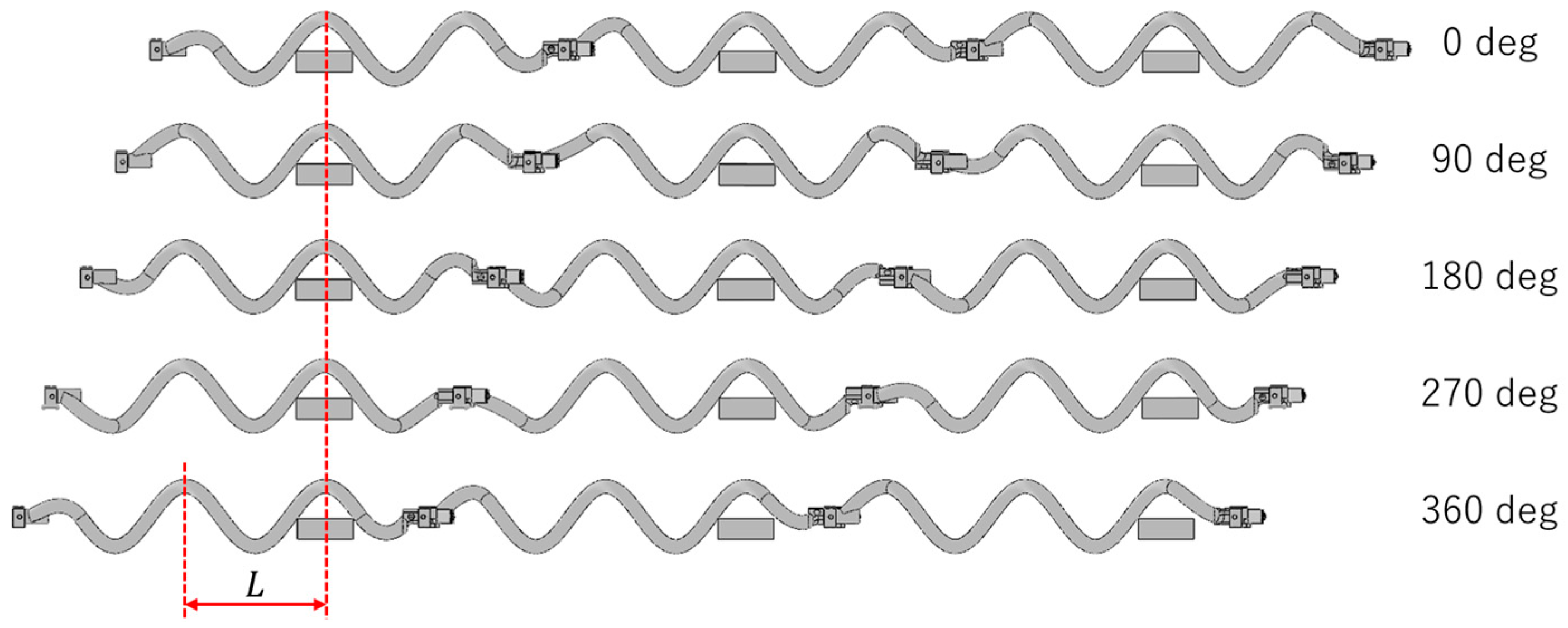
To address the issues identified with the preliminary RSAW unit, both the helix and the attachment were redesigned to meet the constraints of the cable-laying environments described in Section 2. The helix of the preliminary RSAW unit is shown in Figure 6a, and the parameters of the helix are listed in Table 2. The spiral is divided into an undamped section and a centrally attenuated section, with a wavenumber of 2 in the undamped section. This ensures that the unit always contacts the ground at two points on a flat surface, as shown in Figure 6b. Including the centrally attenuated section, the wavenumber is 2.5. The wavelength and the amplitude are designed to match the sub-beam width of the cable rack (40 mm), as shown in Figure 7. As a result, for example, when three units are connected in series to create a length suitable for propulsion along the cable rack, and assuming there is no friction between the robot and the cable rack, three contact points will always remain in contact with the sub-beam during one rotational cycle, enabling propulsion along the cable rack, as shown in Figure 8. Note that one rotation corresponds to one wavelength .
Figure 6.
Helix of the preliminary RSAW unit.
Table 2.
Parameter of the helix.
Figure 7.
Helix placed on a sub-beam.
Figure 8.
Contact states of three connected environment-specific RSAW units on a cable rack during one rotational cycle.
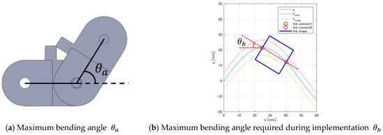
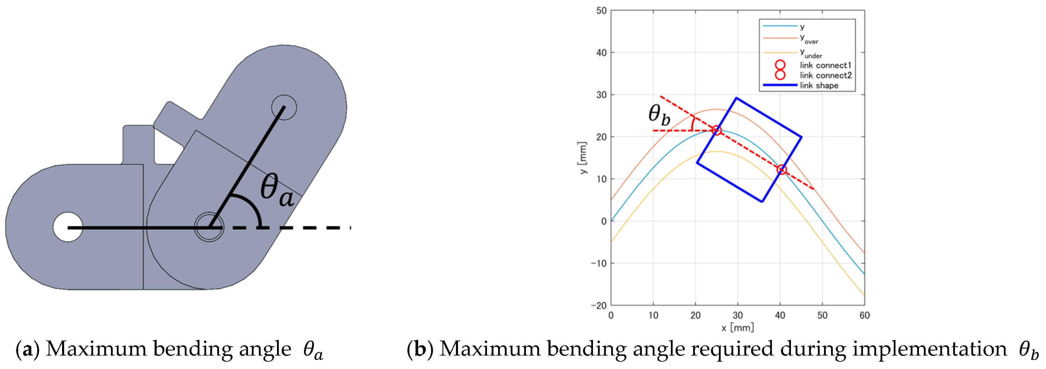
The attachment of the environment-specific RSAW unit is shown in Figure 9, and the parameters of the attachment are listed in Table 3. The attachment was redesigned with no gaps between adjacent elements so that the unit can traverse the ceiling joint receiver without becoming stuck. The height inside the attachment was designed using the model shown in Figure 10 to ensure sufficient clearance for the helix to rotate inside the attachment. The long side was designed to accommodate the 53 mm long side of the helix, which can be derived from the amplitude of the helix and the thickness of the helix . The height , width , and the interval between connections were determined so that the maximum bending angle , shown in Figure 11a, exceeds the maximum bending angle required during implementation , shown in Figure 11b. Based on these parameters, was derived to be 75.7 degrees, and was derived to be 31.2 degrees, which is feasible for implementation.
Figure 9.
Attachment of the environment-specific RSAW unit.
Table 3.
Parameter of the attachment.
Figure 10.
Model of the preliminary RSAW unit.
Figure 11.
Maximum bending angle of the attachment.
The redesigned RSAW unit is shown in Figure 12. When placed on the ceiling joint receiver, this improved design allowed the unit to move smoothly over the ceiling joint receiver, as shown in Figure 13.
Figure 12.
Environment-specific RSAW unit.
Figure 13.
Environment-specific RSAW unit placed on a ceiling joint receiver.
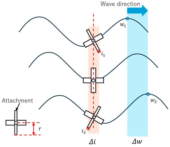
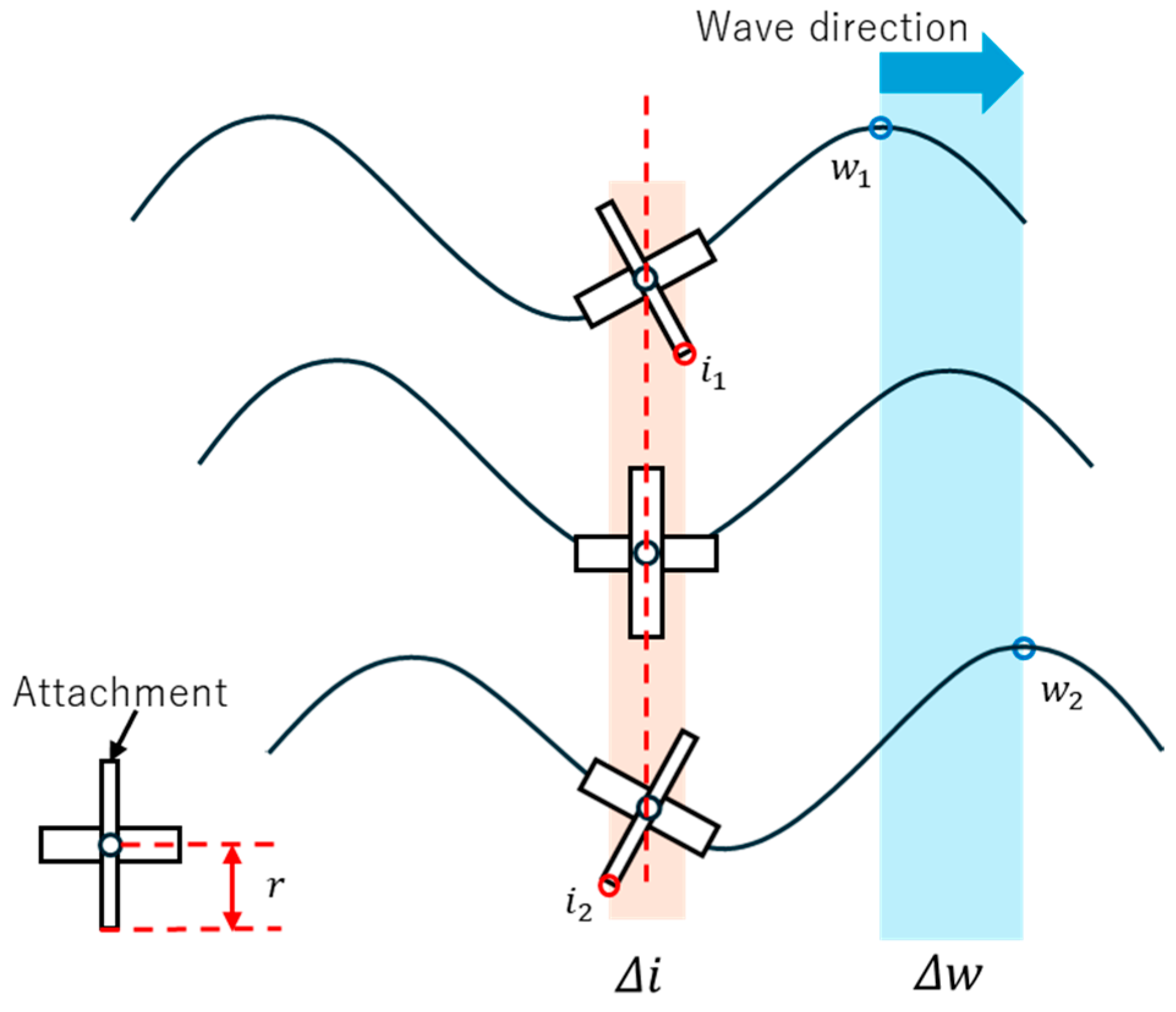
The locomotion of the environment-specific RSAW unit is realized through the interaction between the designed attachment and the surface. As shown in Figure 14, at time the traveling wave is located at and the contact point of the attachment is at , and as the traveling wave propagates to at time , the contact point shifts to due to the change in the attachment angle, resulting in the locomotion of the robot.
Figure 14.
Illustration of contact point transition during wave propagation.
In this case, the velocity of the tip of the attachment can be regarded as a quantity that depends on the parameters of the traveling wave, namely, the amplitude , wavelength , and frequency , where denotes the length of the attachment tip. can be expressed as (12).
In practice, the propulsion of the robot is obtained through interaction with the surface. The thrust force is considered to be generated by the friction force at the contact points between the attachment and the surface. This frictional force can be modeled using Coulomb’s law of friction, shown in (13), where is the kinetic friction force at point , is the coefficient of kinetic friction, and is the normal force at point [36].
However, since the robot operates under multi-point contact conditions, it is difficult to describe its locomotion behavior solely based on a simple single-contact model. Therefore, the locomotion characteristics of the robot were evaluated through experiments conducted in the mock environments described in Section 2.
5. Prototype Active-Cord-Mechanism Robot
This section describes a preliminary experience of connecting multiple environment-specific RSAW units in series following the approach presented in [31]. Based on the environmental constraints described in Section 2, two design requirements were identified: first, a sufficient body length is needed to span the sub-beam intervals of the cable rack; second, at least three links are required to traverse the ceiling joint receivers, as the front unit must climb over the obstacle while the central unit straddles it and the rear unit follows. Based on these requirements, a prototype robot was constructed and tested in both environments.
5.1. Robot Configuration
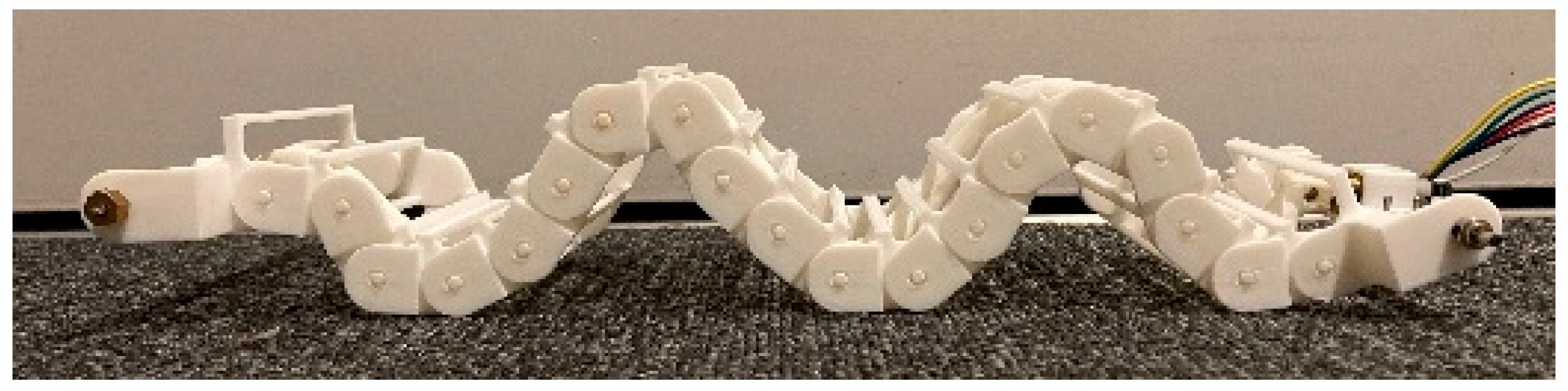
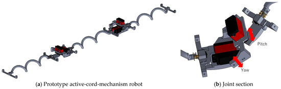
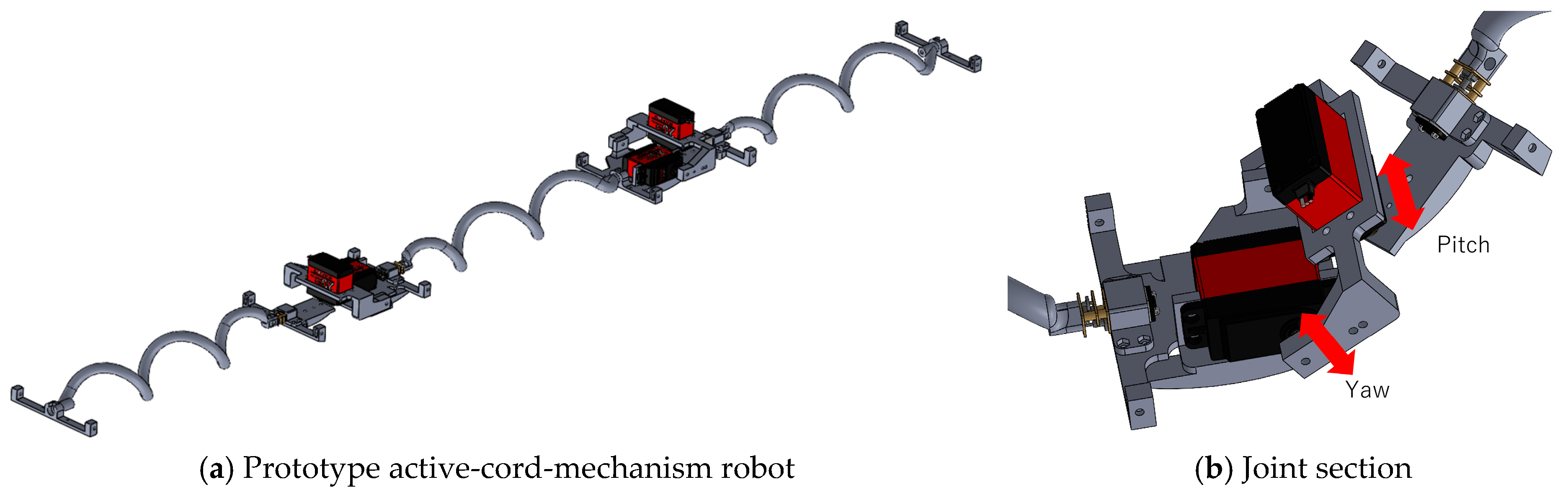
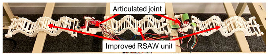
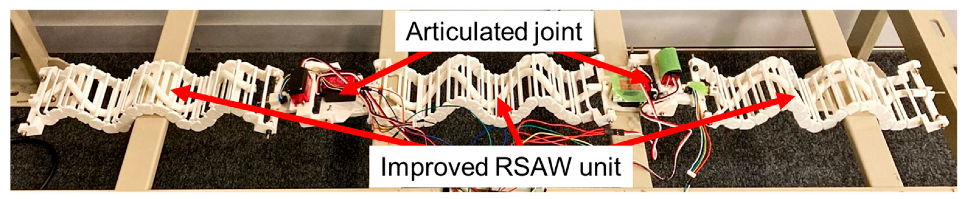
A prototype active-cord-mechanism robot was constructed to verify the mobility requirements identified above. The model of the prototype, shown in Figure 15a, consists of three environment-specific RSAW units connected in series by two articulated joints. Each articulated joint is equipped with two servo motors, enabling rotation around the yaw and pitch axes, as shown in Figure 15b. The resulting robot is shown in Figure 16.
Figure 15.
Model of a prototype active-cord-mechanism robot.
Figure 16.
Prototype active-cord-mechanism robot.
5.2. Operation Verification
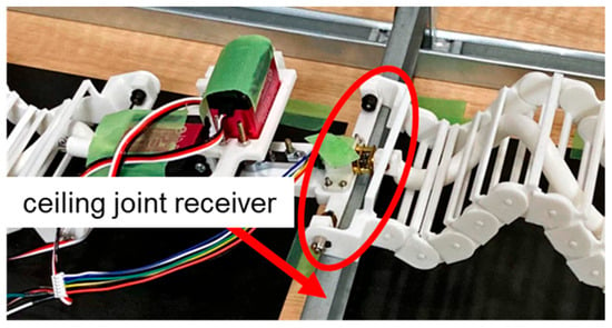
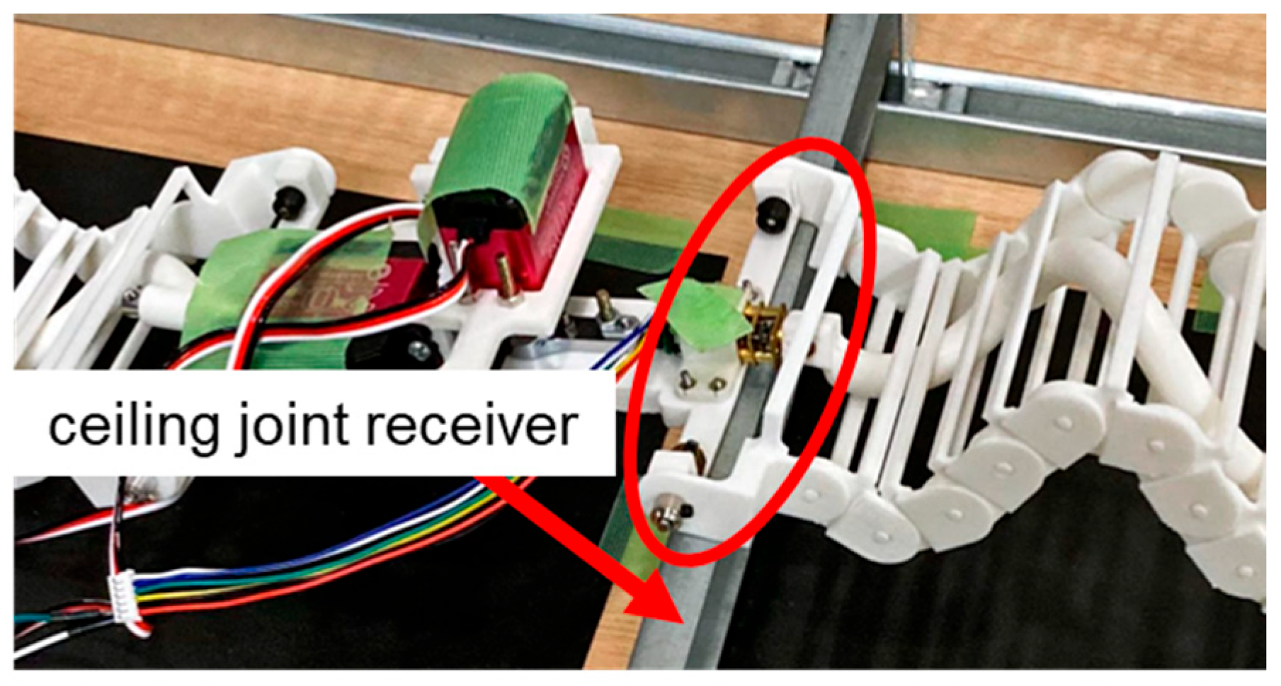
To evaluate the effectiveness of this robot for cable-laying work, operation verification was conducted on the cable rack and in the mock ceiling space. The robot demonstrated the ability to move forward on the cable rack without stalling. However, in the mock ceiling space, the articulated joint got caught on the ceiling joint receiver, preventing complete traversal, as shown in Figure 17. This was attributed to the discontinuity of the traveling wave at the joint connections, which caused the joints to protrude and become caught on the ceiling joint receiver. This finding indicated that maintaining continuity of the traveling wave across the joint connections is essential for traversal in ceiling spaces and that a fundamental redesign of the robot configuration was required.
Figure 17.
Operation verification in the mock ceiling space.
6. Development of a New Active-Cord-Mechanism Robot
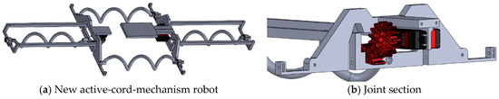
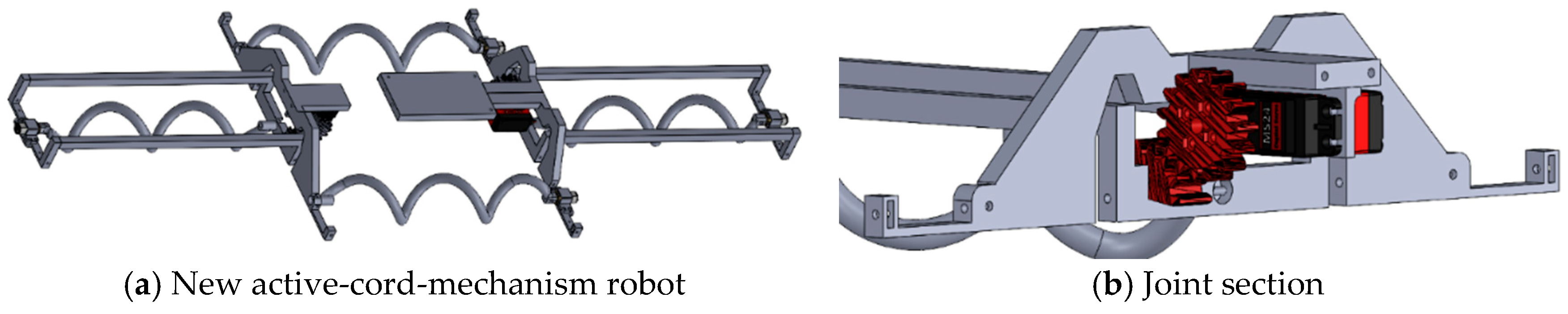
As described in Section 5.2, the discontinuity of the traveling wave at the joint connections was identified as the primary cause of the prototype robot’s failure to traverse the ceiling joint receivers. To address this issue, a new configuration of the RSAW units was designed with the primary objective of maintaining continuous traveling wave propagation across all joint connections. A new configuration of an active-cord mechanism for cable-laying work is shown in Figure 18a.
Figure 18.
Model of new active-cord-mechanism robot.
6.1. Mechanical Design
To prevent joints from catching on the ceiling joint receiver, the connection point between two adjacent units was designed so that the traveling wave is continuous and uninterrupted at the connection point.
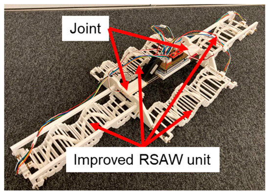
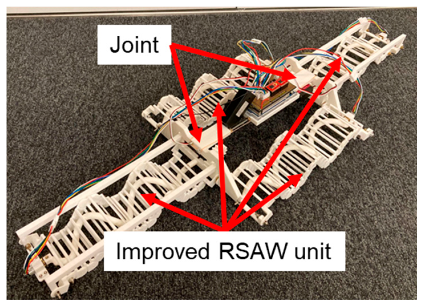
Specifically, the center body of the robot consists of two parallel RSAW units that sandwich the front and rear units. By rotating the helices of the two central RSAW units in opposite directions, the robot’s direction can be changed. Therefore, the degrees of freedom of the yaw axis can be reduced, and only the pitch axis is actuated by the servo motor of each joint. As a result, the total number of servo motors actuating the joints is reduced to two. These servo motors are installed at the top of the RSAW units, as shown in Figure 18b, where they do not interfere with the traveling wave. The motor torque is transmitted via gears, enabling continuous traveling wave propagation even at the connection points around the joints. Additionally, space is provided in the central section of the robot for mounting a battery and an on-board controller, enabling autonomous operation. The new cord-mechanism robot developed based on the above design considerations is shown in Figure 19.
Figure 19.
New active-cord-mechanism robot.
6.2. Phase Synchronization Control
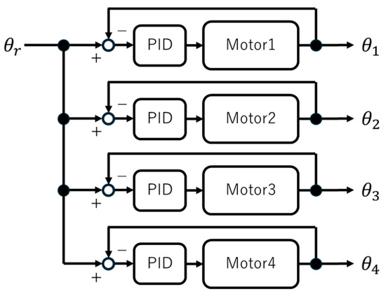
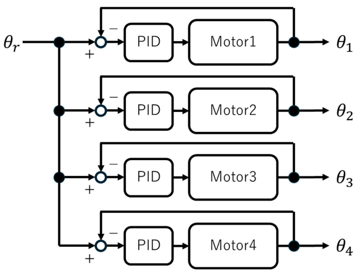
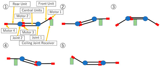
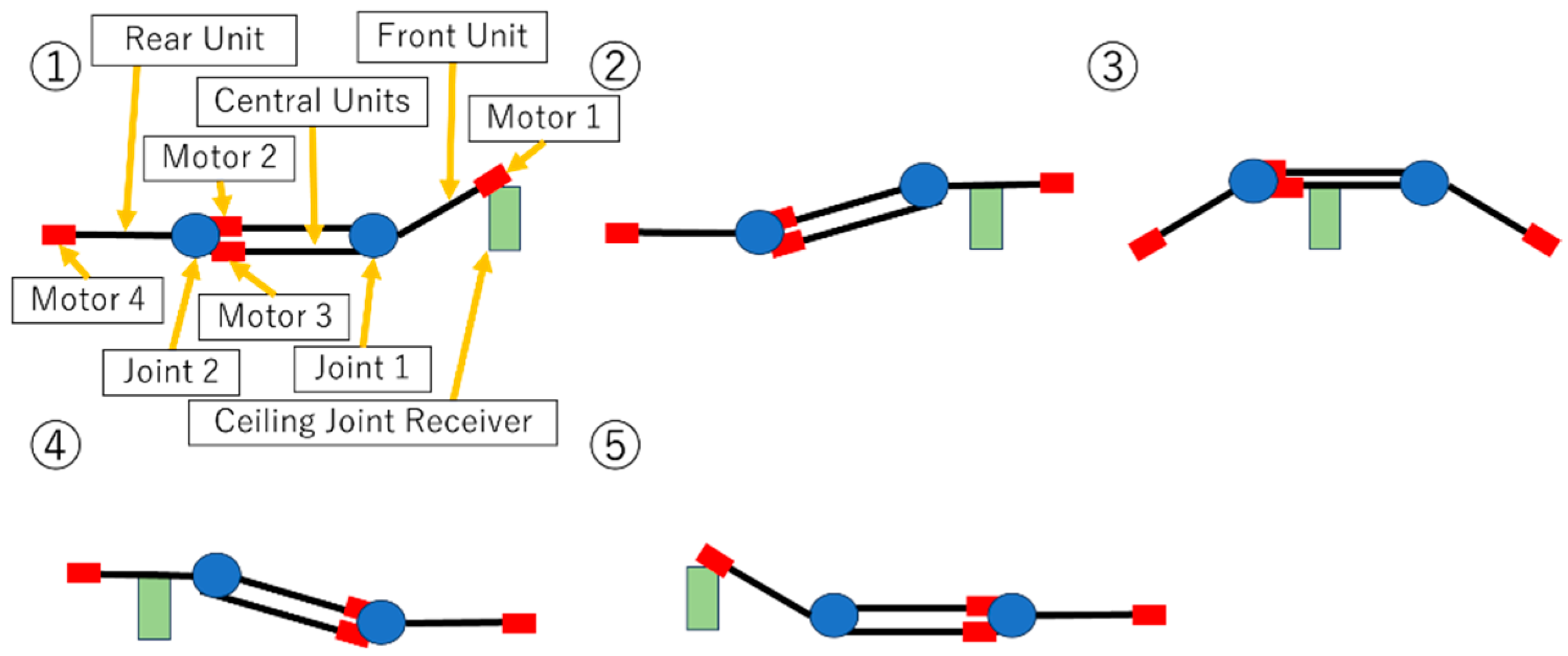
To maintain continuous traveling wave propagation across the joints during operation, it is necessary to align the rotational phases of the helices in the front, central, and rear RSAW units and to synchronize their rotational speeds. To accomplish this, the phase and speed of the traveling waves are controlled using the model indicated by the block diagram shown in Figure 20. This system uses PID control to provide feedback on the relative error between the rotational angles [deg] ( = 1, 2, 3, 4) obtained from the encoders attached to each helix and the target rotational angle [deg]. The P gain value is 50.0, the I gain value is 100.0, the D gain value is 5.0, the sampling rate is 10 ms, the encoder resolution is 3576 counts per motor revolution, and the controller hardware is Arduino MEGA 2560 [37]. This ensures that each helix’s rotational angle follows the target angle. Furthermore, serial communication between the PC and the microcontroller allows keyboard input to switch between forward and backward movement and turning motions, as well as the sequence for moving over the ceiling joint receiver, as shown in Figure 21. The statuses of motors and servo motors for each sequence are listed in Table 4.
Figure 20.
Block diagram.
Figure 21.
Sequence for moving over the ceiling joint receiver.
Table 4.
Statuses of motors and servo motors for each sequence.
7. Operation Verification of the New Cord-Mechanism Robot
This section describes the verification of the new active-cord-mechanism robot, including fundamental motions on a flat surface and traversal over the ceiling joint receiver in the mock ceiling space, to confirm that the wave continuity and phase synchronization achieved in Section 6 enable practical mobility in cable-laying environments.
7.1. Fundamental Motion Verification
Fundamental movements such as forward and backward movement and turning motions of the new active-cord-mechanism robot were verified on a flat surface. When changing the traveling direction, the robot lifts its front and rear units 20 degrees off the ground using servo motors and rotates the helices of the two central RSAW units in opposite directions. Additionally, to evaluate the effectiveness of this robot for cable-laying work, the traction force was measured using a force gauge on the flat floor of the mock ceiling space. Measurements were conducted both with the robot alone and with an increased aluminum weight, which added approximately 1.06 kg.
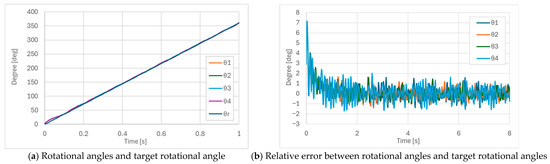
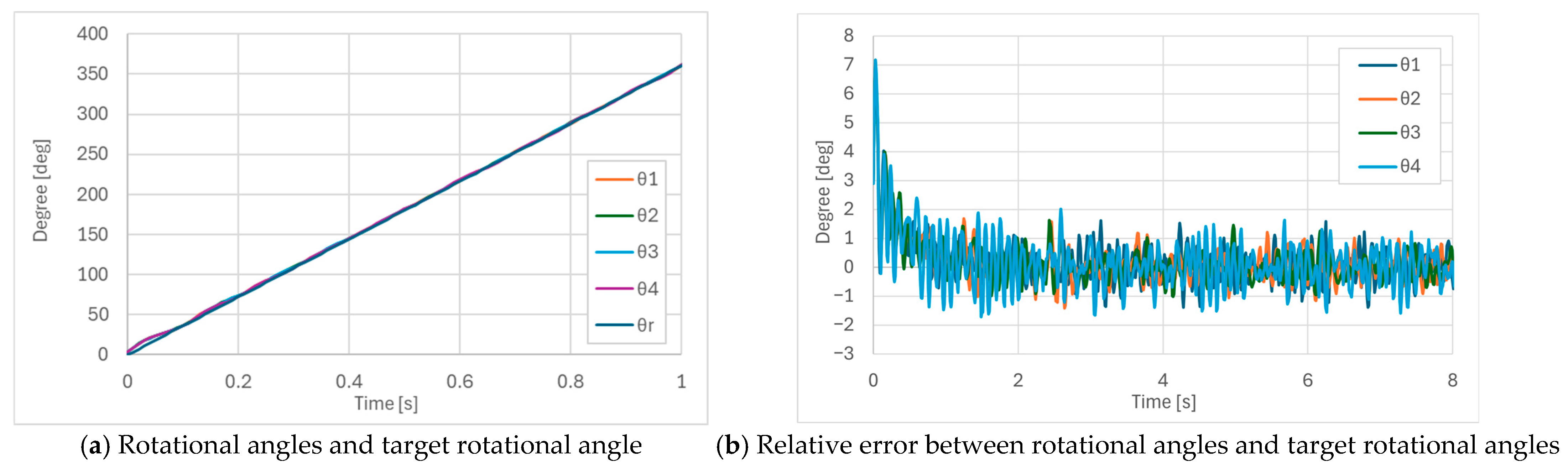
The verification results on the flat surface confirmed that the robot is able to move at a speed of 42 mm/s. Figure 22a shows the rotation angles measured by the encoders attached to each helix and the target rotation angle during forward movement, while Figure 22b shows the relative errors between each rotation angle and the target rotation angle. After the transient response immediately after the movement was corrected, the relative error remained within 2 degrees, demonstrating that all helices successfully followed the target rotational angle.
Figure 22.
Rotational angles and target rotational angles during forward movement.
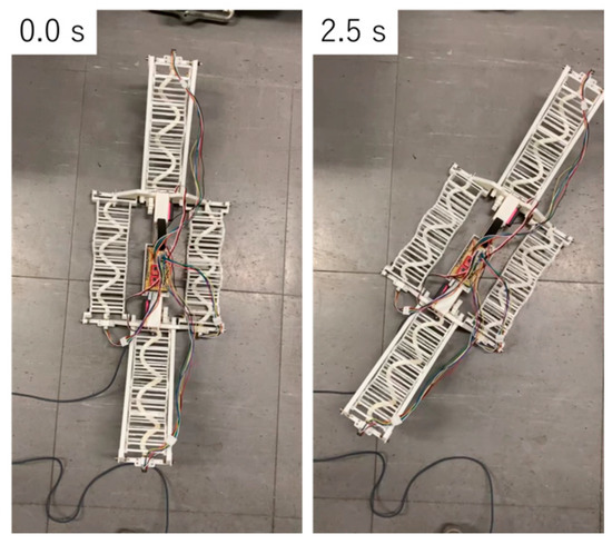
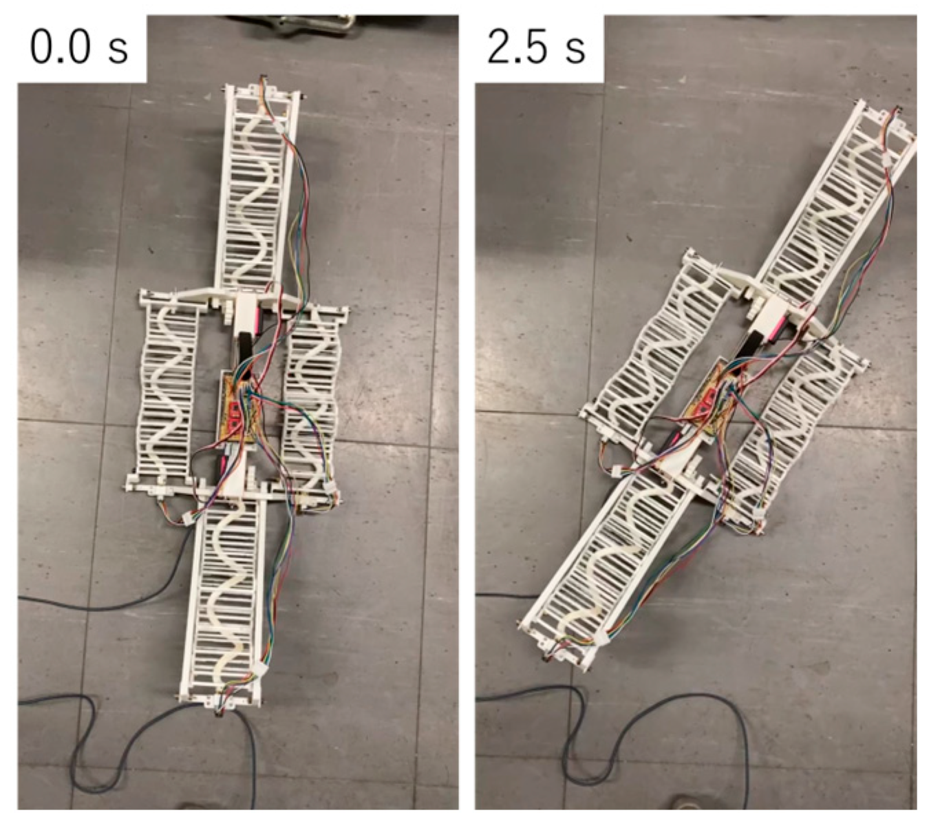
Turning operation results confirmed the robot can turn in both directions, as shown in Figure 23. Because it can turn in place, it can change direction with an almost zero turning radius. During this operation, the front and rear units were lifted 20 degrees. Traction force measurements on the flat floor of the mock ceiling space showed an average of approximately 3.1 N for the robot alone. When weight and friction were increased, the average traction force rose to about 7.5 N. Using these results, a comparison was made between the snake-like robot, the prototype active-cord-mechanism robot, and the new active-cord-mechanism robot. Table 5 summarizes the parameters of each robot. These values were measured on the mock ceiling space.
Figure 23.
Result of turning verification.
Table 5.
Parameter comparison.
The robot in this study has the fewest total motors compared to the snake-like robot, resulting in a lighter body. Additionally, it operates at a lower applied voltage and achieves a higher propulsion speed compared to the snake-like robot. When the weight of this study’s robot was increased by about 1.06 kg to match that of the snake-like robot, it demonstrated comparable traction force. Furthermore, unlike the snake-like robot, which requires an external wired power supply and control signal transmission, the robot in this study is capable of autonomous operation due to its on-board battery and on-board controller. Moreover, the snake-like robot is incapable of turning, and the prototype active-cord-mechanism robot turns by advancing in an arc. In contrast, the robot in this study can perform spin turns. The ease of motor replacement also facilitates the use of high-speed motors to increase propulsion speed.
7.2. Traversal Verification in Mock Ceiling Space
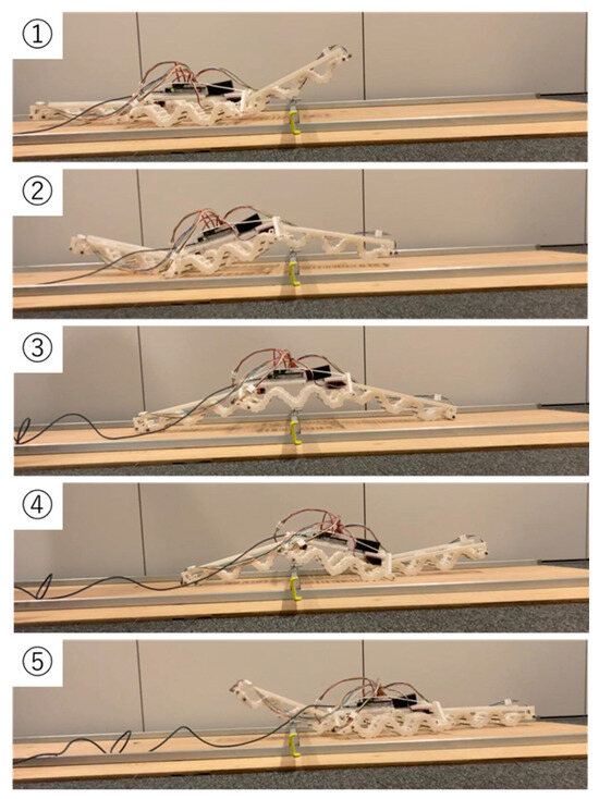
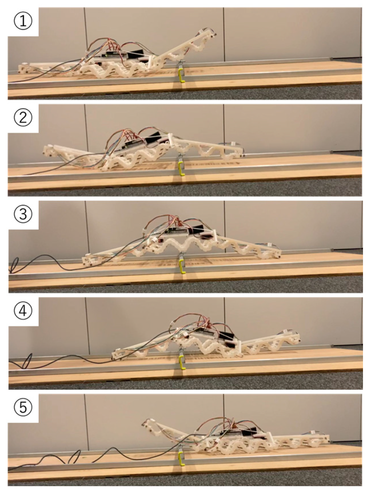
To verify the traversal capability in ceiling spaces, the robot’s ability to move over the ceiling joint receiver was tested in the mock ceiling space described in Section 2, as illustrated in Figure 24. The robot successfully traversed the ceiling joint receiver through the phase transitions in the sequence shown in Figure 21, confirming that the phase synchronization control described in Section 6.2 functioned effectively. It took approximately 60 s for the robot to move from contact with the ceiling joint receiver to complete detachment.
Figure 24.
Result of moving over the ceiling joint receiver.
8. Discussion
In this study, a reconfigured active-cord-mechanism robot based on the RSAW mechanism was developed for cable-laying applications in ceiling spaces and on cable racks. The central design challenge was maintaining continuity of the traveling wave across the joint connections between multiple RSAW units, which was identified as the primary cause of failure in the prototype robot. This was addressed through two complementary approaches: a mechanical design that transmits motor torque via gears to ensure uninterrupted wave propagation at the connection points and a phase synchronization control that aligns the rotational phases of all helices during operation.
Operational verification confirmed that the developed robot can perform forward and backward movement and turning motions on a flat surface. In comparison with the snake-like robot and the prototype robot developed in previous studies, the proposed robot can move independently and can also turn, even though it uses the fewest total number of motors. This means that the proposed robot solves several limitations of the prototype robot. In addition, the proposed robot demonstrated its ability to move over a ceiling joint receiver in the mock ceiling space. This motion cannot be realized by the prototype robot.
In the future, we plan to increase the motor speed and adjust the joint motion between the RSAW units to reduce the time required to move over the ceiling joint receiver. Furthermore, this study focused on verifying the fundamental mobility and phase synchronization of the proposed robot configuration. Although traction force was measured with an added weight to approximate practical load conditions, sustained-load and endurance tests under realistic cable-laying conditions were not conducted. These tests require a more robust prototype capable of withstanding repeated operation over longer distances and heavier cable loads. Therefore, sustained-load and endurance tests are identified as future work to be conducted once a reinforced prototype has been developed.
Author Contributions
Conceptualization, F.I. and Y.S.; methodology, F.I. and Y.S.; software, F.I. and Y.S.; validation, F.I. and Y.S.; formal analysis, F.I. and Y.S.; investigation, F.I. and Y.S.; resources, F.I. and Y.S.; data curation, F.I. and Y.S.; writing—original draft preparation, F.I.; writing—review and editing, M.I.; visualization, F.I.; supervision, M.I.; project administration, M.I.; funding acquisition, M.I. All authors have read and agreed to the published version of the manuscript.
Funding
This research received no external funding.
Data Availability Statement
The original contributions presented in this study are included in the article. Further inquiries can be directed to the corresponding author.
Acknowledgments
The authors would like to express their sincere gratitude to TOKO ELECTRICAL CONSTRUCTION Co., Ltd. for their valuable advice regarding the experiments.
Conflicts of Interest
The authors declare no conflicts of interest.
References
- Ministry of Land, Infrastructure, Transport and Tourism. Current Status and Challenges Surrounding the Construction Industry. Available online: https://www.mlit.go.jp/policy/shingikai/content/001610913.pdf (accessed on 12 July 2024).
- Research Institute on Building Cost. Productivity Improvement Through the Development of a Robot for Ceiling Wiring. Available online: https://www.ribc.or.jp/info/pdf/sprep/sprep101_05.pdf (accessed on 14 March 2026).
- Kinden Corporation. Cable-Laying Rope Installation Device Hashirundesu yo. Available online: https://www.kinden.co.jp/pdf/dev_011.pdf (accessed on 12 July 2024).
- Huang, X.; Xiang, H.; Wu, C.; Xu, J.; Ding, J.; Peng, Y.; Funabora, Y. CRAB-EDM: A Multi-Modal Underwater Crab-Inspired Robot With Temporally Sequenced Electro-Discharge Modulation. IEEE Robot. Autom. Lett. 2026, 11, 3939–3946. [Google Scholar] [CrossRef] [Scilit]
- Wu, Q.; Qiu, Z.; Ma, Y.; Fang, Y.; Sun, N. Crocodile-Inspired Soft Robots with Spatial Bending Leg Actuators and Coordinated Locomotion Planning for Amphibious Environments. IEEE Trans. Ind. Electron. 2025, 72, 14553–14562. [Google Scholar] [CrossRef] [Scilit]
- Dachlika, T.; Zarrouk, D. Mechanics of locomotion of a double screw crawling robot. Mech. Mach. Theory 2020, 153, 104010. [Google Scholar] [CrossRef] [Scilit]
- Yamada, H.; Hirose, S. Research on cord-like active bodies. J. Robot. Soc. Jpn. 2008, 26, 801–811. (In Japanese) [Google Scholar] [CrossRef] [Scilit]
- Liu, J.; Tong, Y.; Liu, J. Review of snake robots in constrained environments. Robot. Auton. Syst. 2021, 141, 103785. [Google Scholar] [CrossRef] [Scilit]
- Suhara, H.; Kamegawa, T.; Gofuku, A. Realization of a snake robot that passes through inside of bent pipe connected with straight pipes by helical rolling motion. Proc. Robot. Mechatron. Conf. 2016, 6, 36. (In Japanese) [Google Scholar] [CrossRef] [Scilit]
- Ito, K.; Murai, R.; Nakamichi, K. Development of snake-like rescue robot designed for ease of use. J. Robot. Soc. Jpn. 2009, 27, 419. [Google Scholar] [CrossRef] [Scilit]
- Han, S.; Chon, S.; Kim, J.; Seo, J.; Shin, D.G.; Park, S.; Kim, J.T.; Kim, J.; Jin, M.; Cho, J. Snake robot gripper module for search and rescue in narrow spaces. IEEE Robot. Autom. Lett. 2022, 7, 1667–1674. [Google Scholar] [CrossRef] [Scilit]
- Takahiro, M.; Masami, I.; Shoshiro, H. A design and control of a snake-like robot using projection method. Proc. SICE Annu. Conf. 2004, 47, 213. [Google Scholar] [CrossRef]
- Mori, M.; Yamada, H.; Hirose, S. Design and development of active cord mechanism “ACM-R3” and its 3-dimensional locomotion control. J. Robot. Soc. Jpn. 2005, 23, 886. (In Japanese) [Google Scholar] [CrossRef] [Scilit]
- Yamakita, M.; Hashimoto, M.; Yamada, T. Control of locomotion and head configuration for 3D snake robot. J. Robot. Soc. Jpn. 2004, 22, 61. [Google Scholar] [CrossRef] [Scilit]
- Kasahara, F.; Yanagida, T.; Onodera, K.; Iwase, M. Modeling and locomotion control using SDRE of snake-like robot considering side-slip. Trans. JSST 2008, 10, 35. [Google Scholar]
- Marvi, H.; Gong, C.; Gravish, N.; Astley, H.; Travers, M.; Hatton, R.L.; Mendelson, J.R.; Choset, H.; Hu, D.L.; Goldman, D.I. Sidewinding with minimal slip: Snake and robot ascent of sandy slopes. Science 2014, 346, 224. [Google Scholar] [CrossRef] [Scilit]
- Tate, T.; Tsukagoshi, H. Fluid powered soft cord robot aiming to move in the sand. Proc. Robot. Mechatron. Conf. 2016, 2016, 2A1-04b2. (In Japanese) [Google Scholar] [CrossRef] [Scilit]
- Zuo, Z.; Wang, Z.; Li, B.; Ma, S. Serpentine locomotion of a snake-like robot in water environment. In Proceedings of the 2008 IEEE International Conference on Robotics and Biomimetics, Bangkok, Thailand, 22–25 February 2009; p. 25. [Google Scholar] [CrossRef] [Scilit]
- Crespi, A.; Ijspeert, A.J. Online optimization of swimming and crawling in an amphibious snake robot. IEEE Trans. Robot. 2008, 24, 75–88. [Google Scholar] [CrossRef] [Scilit]
- Kelasidi, E.; Liljeback, P.; Pettersen, K.Y.; Gravdahl, J.T. Innovation in underwater robots: Biologically inspired swimming snake robots. IEEE Robot. Autom. Mag. 2016, 23, 44–54. [Google Scholar] [CrossRef] [Scilit]
- Sangchul, H.; Sanguk, C.; Jung Yeong, K.; Jeahong, S.; Dong Gwan, S. Abstraction of state-action space utilizing properties of the body and the environment—Application to a 3-dimensional snake-like robot that operates on rubble. In Proceedings of the 2012 6th IEEE International Conference Intelligent Systems, Sofia, Bulgaria, 6–8 September 2012; p. 114. [Google Scholar] [CrossRef] [Scilit]
- Kouno, K.; Yamada, H.; Hirose, S. Development of active-joint active-wheel high traversability snake-like robot ACM-R4.2. J. Robot. Mechatron. 2013, 25, 559. [Google Scholar] [CrossRef] [Scilit]
- Tatsuya, T.; Motoyasu, T.; Fumitoshi, M. Ladder climbing with a snake robot. In Proceedings of the 2018 IEEE/RSJ International Conference on Intelligent Robots and Systems (IROS), Madrid, Spain, 1–5 October 2018. [Google Scholar] [CrossRef] [Scilit]
- Tanaka, M.; Nakajima, M.; Suzuki, Y.; Tanaka, K. Development and control of articulated mobile robot for climbing steep stairs. IEEE/ASME Trans. Mechatron. 2018, 23, 531. [Google Scholar] [CrossRef] [Scilit]
- Tanaka, M.; Kon, K.; Nakajima, M.; Matsumoto, N.; Fukumura, S.; Fukui, K.; Sawabe, H.; Fujita, M.; Tadakuma, K. Development and field test of the articulated mobile robot T2 Snake-4 for plant disaster prevention. Adv. Robot. 2020, 34, 70–88. [Google Scholar] [CrossRef] [Scilit]
- Watanabe, R.; Tanaka, M. Principle of object support by rope deformation and its application to rope climbing by snake robot. Adv. Robot. 2023, 37, 591. [Google Scholar] [CrossRef] [Scilit]
- Takayama, T.; Hirose, S.; Arai, M. Development of “Souryu-III”: Connected crawler vehicle for inspection of narrow and winding space. Proc. JSME Annu. Conf. Robot. Mechatron. Robomec 2003, 2003, 100. (In Japanese) [Google Scholar] [CrossRef] [Scilit]
- Fu, Q.; Li, C. Contact feedback helps snake robots propel against uneven terrain using vertical bending. Bioinspir. Biomimet. 2023, 18, 056672. [Google Scholar] [CrossRef] [Scilit]
- Sadasue, Y.; Nagae, H.; Takarabe, J.; Iwase, M. Development of snake-like robot for cable-laying. J. Robot. Mechatron. 2024, 36, 27367548. [Google Scholar] [CrossRef] [Scilit]
- Ministry of Land, Infrastructure, Transport and Tourism. Overall Picture of Measures Against Falling Ceilings in Buildings. Available online: https://www.mlit.go.jp/common/001009501.pdf (accessed on 6 February 2025).
- Zarrouk, D.; Mann, M.; Degani, N.; Yehuda, T.; Jarbi, N.; Hess, A. Single actuator wave-like robot (SAW): Design, modeling, and experiments. Bioinspiration Biomimet. 2016, 11, 046004. [Google Scholar] [CrossRef] [Scilit] [PubMed]
- Shachaf, D.; Inbar, O.; Zarrouk, D. RSAW, a highly reconfigurable wave robot: Analysis, design, and experiments. IEEE Robot. Autom. Lett. 2019, 4, 2932–2938. [Google Scholar] [CrossRef]
- Sekiden-k-so Corporation. Cable Rack Width Calculation. Available online: https://sekiden-k-so.com/gijutsu/cablerack/ (accessed on 14 March 2026).
- Ministry of Land, Infrastructure, Transport and Tourism. Standard Specifications for Public Building Construction Works (Architectural Works Edition). Available online: https://www.mlit.go.jp/gobuild/content/001888816.pdf (accessed on 25 February 2026).
- Tsubakimoto Chain Corporation. Cable Carriers (CABLEVEYOR) Plastic Open Type. Available online: https://tt-net.tsubakimoto.co.jp/tecs/pdct/ccv/pdct_ccv_1cvplo.asp (accessed on 6 February 2025).
- Kolani, M.R.; Jalali, A.M.; Zareinejad, M.; Ghafarirad, H. Adjustable Wave-like Robot (AWR): Design, analysis, and experiment. Mech. Based Des. Struct. Mach. 2024, 53, 7848–7864. [Google Scholar] [CrossRef] [Scilit]
- Arduino. Mega 2560 Rev3. Available online: https://docs.arduino.cc/hardware/mega-2560 (accessed on 19 March 2026).

Disclaimer/Publisher’s Note: The statements, opinions and data contained in all publications are solely those of the individual author(s) and contributor(s) and not of MDPI and/or the editor(s). MDPI and/or the editor(s) disclaim responsibility for any injury to people or property resulting from any ideas, methods, instructions or products referred to in the content. |
© 2026 by the authors. Licensee MDPI, Basel, Switzerland. This article is an open access article distributed under the terms and conditions of the Creative Commons Attribution (CC BY) license.