


Abstract
Seamless Copper Tube Manufacturing (SCTM) is a multi-stage manufacturing chain, typically comprising billet casting, hot extrusion, cold drawing or pilgering, intermediate annealing, and finishing operations. Despite the fact that quality control (QC) practices are implemented at individual stages, many product deviations originated from cumulative thermomechanical and metallurgical interactions across multiple processes. Thus, although the current stage-wise QC schema ensures compliance with quality standards, it’s questionable whether it can identify root causes or implement proactive QC at the production level. This study presents a narrative review of QC approaches in SCTM, examining the production chain across key quality domains, including billet integrity, extrusion tooling condition, dimensional control, surface and internal defect detection, annealing atmosphere monitoring, and inner-surface cleanliness. The industrial practices are critically compared with research approaches in numerical modelling, advanced sensing technologies, and data-driven monitoring methods. Results confirmed that dimensional instability, defect formation, surface contamination, and microstructural variation in the tube are influenced by interactions among factors such as billet quality, thermomechanical conditions during extrusion and drawing, annealing conditions, tooling conditions, lubrication regimes, and handling between processing steps. Their analysis indicated that the main limitation of current QC frameworks is not the lack of monitoring or modelling technologies but the limited integration of process data across the manufacturing chain.
1. Introduction
The first step in Seamless Copper Tube Manufacturing (SCTM) involves extruding a heated copper billet over a mandrel to form an initial “mother tube” shell [1]. This shell is then pulled through a series of progressively smaller dies during cold drawing or pilgering to reach the final dimensions, using intermediate annealing to maintain the material’s malleability [2,3]. Tubes are manufactured to various standards, such as ASTM B88 for plumbing, ASTM B42 for industrial piping, ASTM B280 for refrigeration & HVAC systems, and ASTM B837 for natural gas and liquefied petroleum systems [4,5,6,7,8]. These standards specify features such as wall thickness, soft annealing for easy bending, and internal grooving to improve heat conduction in modern cooling equipment.
Quality control in SCMT presents several challenges at both the process and production levels, as product defects and low quality arise from the interaction of anomalous thermomechanical and metallurgical phenomena across the involved sequential processing [9]. Focusing on the latter, dimensional non-uniformity, increased number of surface artifacts, residual stresses, and corrosion susceptibility are initiated upstream (during billet preparation and extrusion), whereas detection occurs downstream (during drawing or final inspection). Thus, stage-wise inspection alone may ensure compliance but does not necessarily enable root-cause prevention, which would ultimately improve product/production quality.
This study provides a narrative review of quality control in SCTM, synthesizing the literature along cross-process quality axes and identifying recurring bottlenecks affecting product integrity and process stability. The general objective of this review is to examine how quality control is currently implemented across the main stages of SCTM and to identify the technological and methodological limitations that hinder predictive and integrated quality management. To achieve this objective, the study (i) analyses the principal quality-control domains involved in the production chain, including billet integrity, extrusion tooling, dimensional control, surface integrity, and annealing atmosphere monitoring; (ii) contrasts current industrial practices with emerging modelling, sensing, and digitalization approaches reported in the literature; and (iii) identifies cross-process technological gaps and research directions that could support the development of more integrated quality-control frameworks.
While prior review studies in metal forming have examined process-level monitoring, modelling, and inspection strategies, these are typically limited to individual processes (e.g., extrusion or drawing) or to other material systems such as aluminum and steel. On the contrary, the present review focuses specifically on SCTM and adopts a cross-process perspective, emphasizing how quality attributes evolve across multiple sequential stages. The focus is on the lack of integration among process data, inspection systems, and modelling approaches, which is identified as the main limitation of current quality-control frameworks.
The remainder of the paper is organized as follows. Section 2 briefly introduces the manufacturing route for seamless copper tubes and the main process steps that affect product quality. Section 3 reviews the principal quality-control domains across the production chain, discussing current industrial practices, relevant research developments, and associated technological gaps. Section 4 synthesizes the cross-process challenges identified in the literature and discusses the main limitations of current quality-control approaches. Finally, Section 5 summarizes the main findings of the review and outlines directions for future research and industrial implementation.
2. Fundamentals of Seamless Copper Tube Manufacturing
The manufacture of seamless copper tubes can broadly be divided into billet preparation and heating; primary hollow formation (extrusion or piercing); intermediate hot elongation (e.g., spinner block) and/or pilgering; cold drawing (or hot drawing) to final dimensions; annealing; straightening/coiling/cutting; surface finishing; and quality control (Figure 1). Additional routes are adopted for specialized tube products, e.g., IGT tubes and pancake coils for HVACR service. Each production step could potentially affect the microstructure, wall thickness, dimensional accuracy, surface finish, and mechanical performance of the final product.
Figure 1.
Typical SCTM plant layout, (i) Casting, (ii) Gas Furnace Pre-Heating, (iii) Induction Furnace Pre-Heating, (iv) Hot Extrusion, (v) Pilgering, (vi) Drawing, (vii) Annealing, (viii) Inner Grooving.
2.1. Billet Heating and Cleaning
Tube production begins with the preparation of high-purity copper alloy continuous- or semi-continuous-cast billets, whose quality specifications determine the final product’s quality. Hot extrusion, as the name implies, is performed at elevated temperatures, which depend on the material being extruded. For hot working, the billet temperature is typically higher than the temperature required to sustain strain hardening during deformation. This is generally greater than 60% of the metal’s absolute melting temperature. For copper alloys, this ranges from 650 to 1100 °C according to [10] or from 600 to 900 °C according to [11]. In modern production systems, coarse preheating of multiple billets is performed in a multi-zone gas furnace (multi-billet furnaces). This offers a cost-effective solution with gradual heating to avoid steep thermal gradients and internal cracking, but at the expense of longer heating time and the buildup of surface oxides. This step is followed by a fine temperature adjustment in an induction furnace to achieve the billet’s exact temperature prior to extrusion. To this end, induction furnaces provide rapid, uniform, and controllable heating with minimal oxidation and scale formation on the billet. Induction furnaces achieve “taper” heating, which is used to achieve a gradient along the length of a billet, a key factor in reducing press die wear and enabling isothermal extrusion at full press speeds [12,13,14]. Finally, the hot billet surfaces are usually cleaned and descaled to remove oxides and contaminants. The most common descaling method includes high-pressure water cleaning (milling) [15].
2.2. Primary Hollow Formation
The formation of a seamless hollow section in the direct extrusion of copper alloys starts with the preparation of the pre-heated solid billet. The billet is placed in the container and pierced by a mandrel to form a concentric cavity prior to extrusion. After piercing is done, the extrusion stem moves forward, and the billet is forced through the die. At the same time, the mandrel is held or moved depending on the press system. Copper tube presses can use stationary mandrels, but moving mandrels are more commonly preferred as they reduce mandrel loading and allow controlled relative motion during extrusion. To avoid the inclusion of oxides and remnants from previous extrusion runs during direct hot extrusion without lubrication, the billet’s outer surface layer shears away, forming a tubular shell against the container wall (which is disposed at the end of the extrusion), ensuring that only clean material enters the deformation zone.
Copper billets are extruded at 600–800 °C, while container temperatures are limited to around 500 °C. The billet’s surface, which is in contact with the container, cools, and the temperature at the entry to the deformation zone decreases, thereby increasing the stem load. Because the billet core remains hotter, the flow pattern exhibits pronounced retardation in the outer zones; therefore, excessively long billets should be avoided to prevent defects caused by progressive cooling. Finally, the produced mother tube is cooled immediately after extrusion to control grain formation and surface quality by submerging it directly in water, with cooling tubs extending to the die exit. This step prevents coarse-grain formation and reduces oxidation [11].
2.3. Cold Drawing & Pilgering
Cold drawing is the main deformation process used to shape the extruded or pilgered copper tube into a final product. Drawing reduces the tube’s cross-section by pulling it through a converging die, and the material is subjected to tensile rather than compressive stresses compared to extrusion [16]. Thick-walled mother tubes are commonly fed to a cold pilger mill, where reciprocating tapered rolls reduce wall thickness over a mandrel [17], while thin-walled ones proceed directly to drawing without pilgering, benefiting from the fine-grained and oxide-free condition produced by high-speed underwater extrusion. In SCTM, this combination of material routing plays a dominant role in producing high-quality tubing [18].
Typically, drawing begins with pointing, in which a short length at the tube end is reduced to allow entry into the die. The pointed tube is then clamped to the drawbench carriage and pulled through a die whose geometry determines the final outer diameter, while the choice of internal tool determines the inner diameter [19]. Reductions per pass typically range from 10 to 45%, depending on size and material [16], using some of the available drawing variants, but mostly the floating-plug one, as it accommodates long lengths and enables economical coil production [19].
Modern copper-tube plants employ a structured sequence of pre-drawing, intermediate drawing, and finish drawing. Pre-drawing is typically performed on integrated cascade lines, while intermediate drawing is performed on spinner blocks, which allow continuous multi-pass reduction of long lengths from basket to basket with increased speed and flexibility. Final drawing is performed on two-carriage or chain-track drawing lines, which also include in-line straightening, testing, marking, and cutting systems, thereby imposing the final dimensional accuracy and surface condition [18].
Throughout drawing, process control focuses on die geometry, lubrication quality, and reduction schedule, all of which affect forming loads and surface integrity. Insufficient lubrication increases friction and promotes metal transfer, which can damage both the product and the die [17]. Successive cold reductions produce characteristic strain hardening and induce residual stresses, which may require subsequent annealing depending on the final temper specifications [16].
2.4. Annealing
Annealing is necessary in the production of seamless copper tubes, as the extensive cold work introduced during drawing and/or pilgering increases the strength and reduces the ductility of the product. Copper recrystallizes at relatively low temperatures, typically between 473 and 573 K, and full restoration of properties requires annealing in the range of 533–923 K, depending on the prior cold-work level [16]. In tube production, annealing is used either as intermediate annealing to restore ductility for further drawing or as final annealing for soft-condition products. In conventional extrusion-based routes, soft copper tubes are given a final anneal, whereas half-hard tubes are lightly drawn after annealing to achieve the specified temper [11]. The SMS group has continuous induction annealing lines for soft annealing from coil to coil, operating at speeds up to 500 m/min and incorporating straightening, testing, heating, cooling, and recoiling stages [18]. In annealing furnaces, atmosphere control is also another important aspect because oxygen-containing copper grades may develop hydrogen-induced blistering during annealing, as water vapor forms internally when residual oxygen reacts with hydrogen. To this end, phosphorus-deoxidized grades (SF-Cu) are preferred for annealed tube products [11].
2.5. Internal Grooving
Inner grooving is a specialized finishing process used on heat-exchange products to increase internal surface area and, ultimately, improve thermal conductivity. Inner grooving succeeds drawing and annealing operations and is executed on dedicated high-speed lines. For example, the SMS system employs a spindle-driven grooving head capable of speeds up to 49,000 rpm, enabling line speeds of up to 100 m/min during processing. Tubes are pulled through the grooving unit using the VNVG Veegroove wheel (SMS GROUP GMBH, Mönchengladbach, Germany), which draws them smoothly through, approximately, three-quarters of a turn before coiling, maintaining stable forming conditions and preventing tube damage. Process quality is supported by in-line monitoring. In this case, a flying shear enables inspection sampling without interrupting production, while lubrication systems with controlled flow and pressure ensure tool stability at high spindle speeds [18].
3. Quality Control in Seamless Copper Tube Manufacturing
3.1. Melt & Billet Control
From a quality control perspective, the main challenge at the melt and billet stages is to ensure structural homogeneity and defect-free solidification prior to forming processes. Key performance indicators (KPIs) herein include chemical composition limits, dissolved oxygen and hydrogen levels, inclusion content, macro segregation severity, porosity fraction, and surface-defect density. Unlike dimensional deviations generated during forming, casting-related defects are volumetric and often internal. Once entrapped in the billet, they cannot be eliminated during extrusion or subsequent drawing operations and may propagate as cracks, wall-thickness non-uniformity, or leakage-critical flaws in the final tube. Therefore, billet quality acts as an initial condition for all subsequent forming operations, making upstream variability particularly critical for seamless tube production.
In industrial practice, prior to casting, the melt is refined by deoxidation, slag treatment, filtration, and inert-gas purging in order to minimize dissolved gases and non-metallic inclusions that can lead to internal defects during bulk forming and billet conditioning [20]. The chemical composition and melt cleanliness are checked by sampling of the copper melt [21]. In the continuous or semi-continuous casting of copper-alloy billets, proper mold design, controlled solidification, stable and uniform cooling, and adequate mechanical support during secondary cooling are essential to avoid defects such as internal shrinkage voids, porosity, macrosegregation, and surface or internal cracking, all of which affect billet integrity and extrudability [22]. Cast billets are visually inspected first by surface conditioning (e.g., turning/end cutting) to reveal surface defects, followed by non-destructive testing such as liquid penetrant dye and eddy-current inspection. Internal discontinuities are detected using nondestructive testing (NDT) methods, such as ultrasonic or radiographic methods [23].
Based on the above, the current state of practice appears predominantly inspection-driven and compliance-oriented. Melt treatment and sampling confirm composition and cleanliness at discrete intervals, while billet inspection relies on post-solidification NDT. These measures are effective at rejecting severely defective billets but offer limited predictive capability for defect formation mechanisms. Solidification parameters such as local thermal gradients, sump depth, and melt-flow stability are not typically monitored or controlled in a model-assisted manner during routine industrial casting. Consequently, billet quality is largely assessed ex post rather than controlled through physics-informed prediction of defect susceptibility.
Recent research treats melt and billet quality as a coupled fluid-flow and solidification problem instead of a purely compositional one (Figure 2). In [24], the continuous casting of small-section copper alloy billets intended for subsequent forming and tube production was studied, showing that thermal gradients, cooling intensity, mold design, friction at the solidifying skin, and drawing mode govern solidification stability and the formation of internal and surface defects. Simulations of oxygen-free copper billets under varying boundary conditions, integrating CFD and phase-field approaches, quantified mushy-zone permeability and solid-fraction evolution, thereby providing a mechanistic basis for defect prediction [25,26]. Experimental studies further confirmed that melt-flow control and thermal stabilization during continuous casting improve billet structure and surface quality [27], while combined in-process thermal measurements and solidification modelling during upcasting demonstrated that melt temperature and heat-extraction conditions determine the defect populations inherited by downstream tube forming [28].
Figure 2.
Solidification evolution of Direct-Chill Casting of copper billet FEM—The shape and depth of the liquid sump with different casting speeds [29].
Despite these advances, a gap remains between modelling capability and industrial quality control. Most CFD and CALPHAD solidification models are used for process design or parametric studies rather than embedded in real-time quality monitoring. Furthermore, although research identifies specific causal links between casting parameters and defect formation, these relationships are rarely integrated into extrusion risk assessment or tube-quality forecasting. As a result, billet quality is often treated as a fixed input variable in downstream forming analyses, rather than as a controllable, probabilistic contributor to eccentricity development, surface cracking, or residual-stress heterogeneity.
The melt-and-billet stage is the earliest point at which defects can be prevented in SCTM, yet it remains weakly linked to downstream quality metrics. In contrast, while state-of-the-art modelling approaches provide a mechanistic understanding of defect formation and enable predictive analysis of solidification, industrial quality-control practices remain, for the most part, inspection-based and compliance-oriented, relying on post-solidification evaluation rather than real-time or predictive control. Therefore, the challenge regarding these quality attributes is not a lack of scientific insights, but rather a lack of integration among casting-process variables, solidification models, and extrusion/drawing quality indicators. Without having this link, upstream defects are identified only after significant value has been added to the product, limiting the effectiveness of end-to-end quality control frameworks.
3.2. Annealing Atmosphere Monitoring
The main challenge of annealing atmosphere monitoring is balancing oxidation and avoiding hydrogen-induced damage. KPIs for this quality axis include oxygen partial pressure, dew point, hydrogen concentration, furnace temperature uniformity, surface brightness, and final mechanical properties (e.g., ductility and tensile strength). Additionally, indirect indicators such as grain size, texture evolution, and residual stress relaxation are also critical for ensuring downstream tube formability and dimensional stability. While atmosphere composition can be monitored in real time, microstructural outcomes cannot be directly measured during annealing, making annealing a thermochemically controlled but structurally inferred process.
Inert or reducing atmospheres, most commonly nitrogen-based mixtures with limited hydrogen content, are used at industrial sites to keep the oxygen partial pressure below the threshold for copper oxide formation [30]. Studies have shown that reducing the atmosphere suppresses oxidation at elevated temperatures, supporting their use in industrial copper annealing applications such as tube and wire production [31]. However, during high-temperature annealing in hydrogen-containing reducing atmospheres, reactions between residual copper oxides and hydrogen may form water vapor within the metal’s microstructure, contributing to hydrogen-related embrittlement [32]. To address this, commercial bright-annealing systems, such as Linde’s HYDROFLEX, provide a regulated nitrogen–hydrogen gas supply, active furnace atmosphere monitoring, and automatic purge functions to maintain oxidation-free conditions [33].
With that being said, current industrial practice, atmosphere monitoring is mostly compliance-driven. Gas composition and dew point are controlled within predefined thresholds, and surface brightness is used as a visual or measurable indicator of oxidation control. However, these controls primarily target surface integrity rather than subsurface microstructural evolution or hydrogen uptake risk. The prevention of embrittlement relies mainly on limiting hydrogen concentration and selecting appropriate copper grades (e.g., phosphorus-deoxidized copper) [11], rather than on model-assisted prediction of void formation or defect susceptibility. Consequently, the focus remains on maintaining stable furnace conditions rather than predicting metallurgical transformations.
Recent research highlights the microstructural complexity underlying annealing behavior. In [32], even low oxygen levels in copper were shown to lead to micro- and macro-void formation under hydrogen-containing atmospheres. Complementary studies report hydrogen uptake during thermal processing, leading to gas porosity and loss of ductility [34,35]. Beyond embrittlement, texture evolution during annealing significantly influences mechanical performance. Cold-rolled copper exhibits a progressive transformation from deformation textures to recrystallization textures, and eventually to more isotropic structures, with increasing annealing time [36]. Alloying additions and prior deformation history strongly affect recrystallization kinetics [37], while short-duration annealing has been shown to restore ductility while limiting grain growth in deformed oxygen-free copper [38] (Figure 3). These findings demonstrate that annealing is not merely a heat-treatment step but also a process that governs residual stress relaxation, grain refinement, and long-term performance.
Figure 3.
Effects of short-term annealing on the microstructural evolution of oxygen-free copper processed by high-pressure torsion [38]. Different annealing temperature (a) 298 K; (b) 398 K; (c) 423 K.
While research clearly links atmosphere composition and thermal history to hydrogen embrittlement, void formation, and texture evolution, most industrial systems do not integrate predictive microstructural models into routine decision-making. Annealing furnace monitoring systems regulate gas mixtures and temperature but do not assess the recrystallization state, grain-growth risk, or redistribution of residual stress in real time. As a result, annealing quality is evaluated post hoc through mechanical testing and dimensional inspection rather than predicted during processing.
Critically, annealing represents a cross-process stabilization stage in which deformation-induced heterogeneities from extrusion and drawing can be either mitigated or amplified; In this context, a clear distinction s formed between industrial practice and research: while industrial systems focus on maintaining stable furnace atmospheres and preventing oxidation through threshold-based control, research studies demonstrate that atmosphere composition and thermal history govern microstructural evolution, hydrogen embrittlement, and defect formation, highlighting the potential for predictive, microstructure-aware quality control. Thus, the point herein is not atmospheric regulation itself, which is technologically mature, but the limited integration of atmosphere control, which utilizes deformation history, residual stress state, and downstream performance indicators. Bridging this gap would require coupling atmosphere monitoring with microstructure-aware models or soft-sensor approaches capable of estimating recrystallization progress and embrittlement risk during processing. Without such integration, annealing is just another controlled thermal step instead of a fully usable quality-stabilization mechanism within a holistic production framework.
3.3. Surface Cleanliness & Residual Carbon
The cleanliness of the copper tube’s surface depends on managing contamination produced during drawing and auxiliary lubrication processes to ensure reliable corrosion resistance during use. Key performance indicators include the amount of residual carbon per unit area, soluble residue levels, and the effectiveness of lubricant removal. Unlike dimensional tolerances or surface artifacts that can be identified by geometric inspection, residual contamination directly affects copper’s electrochemical behavior during operation. Consequently, surface cleanliness serves as both a manufacturing and a long-term performance measure, linking forming conditions to corrosion risk in downstream applications such as potable water systems and refrigeration circuits.
Lubricants used in the copper tube drawing process leave carbon films on the inner surface, which hinder the formation of a protective corrosion layer and reduce copper’s resistance to corrosion during service [39]. Research studies have shown that residual carbon deposits and contaminated water can promote pitting and corrosion within copper tubes, imposing tight limits on internal residue levels [40]. EU standards specify maximum soluble and lubricant residues on the inner surface, e.g., ≤0.38 mg/dm2 soluble residues and ≤0.20 mg/dm2 for tubes used in medical and refrigeration applications and reference a combustion method for determining inner-surface carbon (EN 723, linked to EN 12735-1 and EN 13348) [41]. Industrial practice achieves these limits using dedicated degreasing and internal-cleaning commercial lines, sometimes described as retro-chemical degreasing plants, combined with visual inspection and reporting of internal carbon limits of approximately 0.20 mg/dm2 [42].
As with the previously mentioned quality attributes in industry, the cleanliness control of copper tubes remains largely compliance-based, with the main objective of ensuring that residual carbon and soluble residues remain below standard-defined limits through cleaning procedures. But this alone does not cover extreme cases, as the controlling schema does not incorporate the upstream production data, e.g., drawing lubrication regimes, die conditions, and process parameters. Thus, there is currently a serious lack of knowledge on how to adjust these cleaning procedures to handle outliers or, to a certain degree, eliminate their generation.
Research studies have examined the mechanistic role of residual carbon in corrosion processes. Failure investigations have shown that localized carbonaceous deposits and entrapped iron hydroxide debris on the inner surfaces of the tubes can create oxygen-deficient micro-environments that promote pitting corrosion through concentration-cell mechanisms [43]. Experimental studies further demonstrate that elevated residual carbon significantly increases pitting susceptibility under certain water chemistries [44]. Additional work has shown that corrosion resistance depends not only on the absolute carbon level but also on its spatial distribution and subsequent mechanical treatments, such as tube expansion [45]. Related studies confirm that residual carbon influences corrosion morphology and copper elution during accelerated testing [46]. Broader reviews on copper corrosion mechanisms emphasize that surface contaminants, including organic and carbonaceous films, modify local electrochemical behavior and act as nucleation sites for corrosion pits [47].
While research clearly demonstrates the interaction among residual carbon, water chemistry, and surface morphology, it treats quality control along the line of industrial practice, treating carbon contamination as a threshold parameter rather than a process-dependent variable. The connection among forming lubrication, lubricant degradation, cleaning efficiency, and long-term corrosion performance is rarely modeled or systematically monitored. Consequently, the diagnostic potential of cleanliness measurements to improve upstream forming processes in the context of surface cleanliness remains underutilized, and there is no clear strategy for handling extreme cases that do not comply.
To this end, a clear distinction can be made between industrial practice and research approaches, with the first one treating residual carbon mainly as a threshold-based parameter to ensure compliance with cleanliness standards, and the latter highlighting its process-dependent nature and its direct influence on corrosion mechanisms. So, despite some insights linking surface cleanliness to the degradation of certain tube performance indicators during service, there is a serious lack of cleanliness control in upstream manufacturing processes.
As a result, the control of residual carbon remains reactive and will require at least some attention to correlating process-related parameters with measured contamination levels as a first step. This will enable predicting surface contamination later and optimizing the process from a surface cleanliness perspective.
3.4. Dimensional Control
One of the major challenges in SCTM is maintaining the tube’s dimensional stability across multiple forming stages under varying thermomechanical conditions. Herein, the outer-diameter tolerance, eccentricity, and ovality are some of the most important KPIs for this quality schema. These metrics, in addition to defining the product’s conformity to dimensional standards, influence downstream properties such as structural integrity, mechanical performance, and fatigue resistance. Dimensional deviations most often originate from asymmetric material flow during extrusion and uneven deformation during drawing, or, in general, from residual stress gradients introduced during forming. As a result, dimensional control is a cumulative quality attribute influenced by upstream process conditions and not a purely local measurement problem.
Dimensional control in copper tube production is governed by standards such as EN 1057, which specify the allowable tolerances for outside diameter, wall thickness, and ovality for seamless copper tubes. These standards define the allowable deviation of the outside diameter as a tolerance on the mean diameter, including ovality, with different values listed for each nominal size [48]. For example, manufacturer data sheets that comply with EN 1057, such as those from Lawton Tubes, specify a tolerance of ±0.04 mm on the “mean diameter including ovality” for standard plumbing-tube sizes [49]. Similarly, HALCOR datasheets include comparable dimensional tables consistent with EN standards [8]. In continuous production, dimensional control is maintained using non-contact inline metrology. X-ray systems such as the SIKORA X-RAY 6000 PRO (SIKORA GmbH, Bremen, Germany) measure wall thickness, diameter, and ovality independently of material and are marketed for tube extrusion lines as online quality-control systems [50]. IMS Messsysteme (IMS Messsysteme GmbH, Heiligenhaus, Germany) provides inline measuring solutions for tube mills that measure wall thickness, eccentricity, diameter, and profile of ferrous and non-ferrous tubes in continuous production [51]. For copper-tube drawing lines, SMS provides its ProConTube solution, which uses circumferential wall-thickness sensing and mechanical correction upstream of the drawing unit to reduce eccentricity by approximately 2–3% [18]. Dimensional evaluation also includes offline sampling inspection, such as ultrasonic thickness gauges, which enable the measurement of wall thickness along the tube length without destructive sectioning [52].
So, in the current state of practice, dimensional control is primarily measurement-driven, either through sampling (for large-diameter products) or through inline measurement (for small-diameter products), with the latter providing continuous monitoring of tube geometry and enabling automated, configurable detection of deviations from specifications. When dimensional drift is detected, corrective actions typically involve adjusting the process parameters of the related process or aligning the involved tools. While such measures can reduce eccentricity or diameter deviations, they do not point out the upstream causes that generated the asymmetry. Consequently, current dimensional control strategies focus on detecting and partially correcting deviations after they occur rather than providing insights for fully or partially avoiding their formation.
Recent research has investigated the mechanisms responsible for dimensional deviations in extrusion and drawing processes. Finite-element modelling (FEM) studies have demonstrated that eccentricity development along the length of the copper tube is strongly influenced by billet upset completeness, mandrel alignment, and friction conditions during extrusion [53]. These studies show that eccentricity is primarily generated during extrusion, with only limited correction occurring during downstream drawing. Similar findings have been reported in aluminium and steel extrusion processes, where three-dimensional FE models and industrial observations demonstrate that die asymmetry and non-uniform material flow lead to dimensional non-uniformity and wall-thickness variation [54,55,56] (Figure 4). Reviews of extrusion processes further highlight the influence of die alignment, bearing geometry, and friction asymmetry on dimensional accuracy [57].
Figure 4.
FEM numerical and experimental study on dimensional accuracy of tubes, colored maps of deviations for tubes extruded from 7021 alloy using different dies (wall thickness on the left and roundness deviations on the right) [54]. (a) die design 1; (b) die design 2; (c) die design 3.
For cold drawing, FE simulations of copper tubes indicate that die angle, reduction ratio, and plug geometry control wall-thickness distribution, ovality, and eccentricity, with neutron-diffraction-based validation confirming realistic predictions of industrial eccentricity levels when geometric non-uniformity is included in the model [58]. Experimental and modelling studies in aluminium and steel drawing also show that tooling geometry and reduction schedules systematically influence thickness variation and ovality [57]. Additionally, asymmetric deformation during drawing has been shown to generate residual stress gradients that affect straightness, ovality, and dimensional repeatability [59,60], while further work links wall-thickness variation and eccentricity directly to the magnitude and distribution of residual stresses [61].
For in-process dimensional monitoring, optical and laser-based methods such as laser triangulation, structured light, and laser line scanning have been identified as mature technologies for geometric measurement under harsh forming conditions [62,63]. Moving beyond external geometry, wall-thickness measurement technologies based on laser ultrasonics have been proposed for continuous monitoring in tube production lines [64]. These systems have demonstrated the ability to measure wall thickness and even microstructural parameters, such as grain size, in hot metal products [65], with broader reviews confirming laser ultrasonics as a promising tool for high-speed dimensional monitoring in metal-forming environments [66].
While most FE models seem to accurately predict eccentricity formation, wall-thickness variation, and residual stress evolution, these tools are primarily intended for process design and optimization and are case- and process-dependent. Moreover, to the author’s knowledge, no approach has integrated these models with real-time signals from the underlying process. These challenges are partially addressed by advanced sensing techniques, but only for inline wall-thickness measurement of small-diameter tubes, and without any prediction of future values. Again, these techniques do not incorporate any features for real-time process control with respect to this feature, or at least for root-cause analysis to aid knowledge-based post-process adjustments.
To summarize, although dimensional control provides the means for real-time control, root-cause analysis, and quality prediction, it remains fragmented because no approaches have integrated the underlying technologies to achieve this. On the one hand, industrial systems focus on accurate, real-time measurement and detection of dimensional deviations; on the other, research methods provide insight into the underlying mechanisms of eccentricity and wall-thickness variation, highlighting the potential for predictive and root-cause-oriented quality control. Thus, despite these advances, dimensional control still relies on post-process adjustments on a per-process basis. Moreover, in both state-of-practice and state-of-the-art, there is a lack of a production-wide framework that addresses the cumulative nature of dimensional instability propagation across the forming processes involved. This means independent from the point where dimensional control is implemented within the production chain, the previously mentioned technologies, beyond being integrated in the context of the nearest forming process, also need to be fed with upstream and downstream data in order to offer production-wide insights in order to enable finer management of the dimensional variability.
3.5. Surface-Defect Detection
Identifying critical flaws at production speeds while maintaining a low false-alarm rate is the main goal regarding surface defect detection during SCTM. As such, detection accuracy, probability of detection (POD), false-positive rate (the ability to distinguish relevant defects from harmless surface irregularities), and inspection speed (sampling frequency) are major indicators for evaluating related systems and strategies. Surface defects such as cracks, laps, or inclusions that escape detection may compromise pressure integrity or leak tightness in service applications, particularly in refrigeration and plumbing systems.
In production, surface-defect detection uses Eddy Current Testing (ECT) as a non-destructive method to identify longitudinal and transverse surface discontinuities. Local discontinuities, such as cracks or laps, perturb the induced eddy currents and are detected from changes in probe impedance [67]. For copper-alloy tubes, this practice is formalized by EN 1971-1 and EN 1971-2, which specify procedures for testing seamless round tubes using an encircling test coil on the outer surface and an internal probe on the inner surface, respectively [68,69]. Product standards such as EN 1057 and EN 12735-1 require that each tube undergo ECT in accordance with EN 1971. In industrial copper-tube mills, ECT is implemented as an inline or end-of-line inspection station. Systems such as the FOERSTER DEFECTOMAT (Institut Dr. Foerster GmbH & Co. KG, Reutlingen, Germany) use encircling coils to scan tubes for point and transverse defects, while the CIRCOGRAPH system employs a rotating probe head that scans the surface helically to detect longitudinal flaws [70]. These systems are typically integrated directly into drawing and finishing lines, enabling continuous inspection of the product before final delivery [70]. In accordance with EN 1971-2, signal signatures from material discontinuities are compared with reference artificial defects created in calibration tubes. This approach is intended for reliable detection rather than precise defect sizing because sensitivity decreases with distance from the test coil; therefore, internal probes are less sensitive to outer-surface defects, and vice versa [69]. Commercial Artificial Intelligence (AI) solutions are applied directly to ECT data, typically as add-on modules rather than fully autonomous systems. For example, Eddyfi’s Magnifi software suite includes an AI-based detection module that processes ECT and Eddy Current Array (ECA) data in order to automatically detect and flag indications in pipe and tube inspections [71]. Rohmann has incorporated an AI-enabled eddy-current analysis into its ELOIMAGE software, enabling the system to teach defect patterns and automatically recognize and distinguish them in future inspection runs [72].
In current industrial practice, ECT systems operate using deterministic thresholds and calibration standards. Even when AI-based analysis modules are employed, they typically assist in interpreting the inspection signals rather than replacing the underlying threshold-based detection principle defined by industrial standards. Signals exceeding predefined limits trigger alarms or product rejection, ensuring robust, standardized detection performance. However, this threshold-based approach provides a basic pass/fail product classification rather than detailed defect characterization or root cause analysis. Inspection results are typically used to verify product compliance with standards rather than to identify correlations between defect occurrence and upstream process parameters (e.g., extrusion conditions, tooling wear, or lubrication regimes), or to predict the quality of products that undergo further processing (e.g., drawing, grooving, etc.). As a result, surface-defect detection primarily serves as an intermediate (at best) and a final-inspection barrier rather than an integrated feedback mechanism for process design and improvement or for subsequent quality prediction.
Recent research has focused on improving the robustness and interpretability of eddy-current signals using machine-learning-based approaches. Reviews of machine learning applications in ECT show that classification algorithms and deep neural networks can improve defect detection accuracy and robustness under conditions of signal noise, lift-off variation, and other disturbances typical of industrial environments [73]. Finite-element electromagnetic modelling has also been widely used to predict probe responses across different defect geometries and inspection parameters, supporting systematic evaluation of detection reliability [74]. Such models enable model-assisted Probability-of-Detection analysis, linking simulated signals to detection thresholds or classification algorithms using quantitative metrics such as the a90/95 criterion [74].
Advances in sensor technology have further improved inspection capabilities. Eddy Current Array (ECA) systems, which incorporate multiple sensing elements, provide spatially distributed measurements and significantly improved detection performance compared with single-coil probes. Recent POD studies demonstrate that ECA systems can achieve detection probabilities exceeding 90–95% with 95% confidence for crack-like defects, including backside flaws [75]. Deep-learning approaches are increasingly used to interpret these complex signal datasets. For example, convolutional neural networks capable of exploiting both amplitude and phase information from eddy-current signals have been demonstrated for defect reconstruction and classification [76] (Figure 5). Additional studies propose probabilistic frameworks for defect detection based on signal-distribution modelling, thereby improving reliability in low-signal-to-noise environments [77].
Figure 5.
Complex-valued CNN-Based defect reconstruction of carbon steel from ECT Signals—2D contour plots of pancake coil inductance at 5 kHz frequencies with depths from 0.5 mm to 3.0 mm and lengths of 10 mm [76].
Beyond electromagnetic inspection, optical and vision-based inspection systems have also been explored in related metal-forming industries. Machine-vision systems have demonstrated reliable detection of surface cracks and scratches in steel rolling environments [78], while image-processing approaches combined with machine-learning classifiers have been successfully applied to surface defects in aluminium extrusion [79]. More recent work shows that deep-learning-based vision systems can operate at production speeds in harsh industrial environments, provided that illumination control and representative training data are available [80,81,82]. Although these approaches are not yet widely applied in copper tube manufacturing, they demonstrate the potential of complementary inspection modalities for surface-defect detection.
While these advances clearly boost automation, improve detection accuracy, and enhance the ability to identify different defect types, the same gap as with the state of practice still remains. This means that inspection data are rarely integrated with upstream process data, limiting their usefulness for identifying the root causes of defect formation (e.g., non-optimal process design or malfunctioning machines and tooling) and for predicting product quality in subsequent processing.
Following the previous, there is a difference between inspection capability and the integration of process knowledge in SCTM. On the one hand, current ECT systems provide mature, standardized defect detection; however, their role in quality is limited to basic post-process defect identification. On the other hand, research has shown that advanced modeling can support more precise defect identification.
Thus, this increased resolution in defect identification, along with the use of upstream and downstream production data, could enable the establishment of a broader framework that supports upstream process optimization, downstream product quality prediction, and indirect monitoring of machines and tools.
3.6. Extrusion Tooling
From a quality-control perspective, the main challenge associated with extrusion tooling is maintaining geometric alignment and tool integrity under high temperatures, pressures, and friction. KPIs herein include tooling alignment relative to the press axis; die and container inner-liner wear; stability of the extrusion force–displacement pattern; and the resulting wall-thickness uniformity of the mother tube. The importance of extrusion tooling conditions lies in the simple fact that extrusion is the first forming step in seamless tube production; geometric deviations generated at this stage propagate into subsequent pilgering/drawing operations and may be only partially corrected downstream. Consequently, the condition of the extrusion tooling is one of the main factors in establishing the baseline dimensional quality of the tube.
As previously mentioned, the dimensional stability and the absence of defects in the extrusion of seamless copper tubes depend strongly on the condition and alignment of the die, mandrel, and container. Small deviations in mandrel centering or tooling conditions can cause measurable eccentricity and non-uniform deformation, underscoring the need to verify and maintain tooling alignment and condition as part of routine inspection [83]. In industrial practice, tooling monitoring relies mainly on periodic inspection and alignment verification. Optical or laser-based alignment systems, dummy tool stacks, and target dies are used to ensure that the mandrel and tooling stack remain concentric with the die opening and press axis [84]. During long extrusion campaigns, maintaining tooling conditions and alignment is critical for achieving consistent product geometry [85]. In addition to alignment verification, some commercial systems provide indirect dimensional correction mechanisms downstream of extrusion. For example, SMS’s ProConTube solution, installed upstream of the drawing unit, uses circumferential wall-thickness sensing and mechanical adjustment to reduce eccentricity by approximately 2–3% [18].
Despite these monitoring capabilities, current industrial practice remains, in most plants, inspection-based, with tool alignment and condition typically verified at scheduled intervals rather than continuously during operation. In some more advanced cases, indirect monitoring might serve as a workaround, yet it does not seem to be the norm. As a result, deviations in mandrel and die positioning, elastic deformation of these, or progressive wear and oxide contamination of the container’s inner layer are becoming evident only indirectly through dimensional and surface-quality drifts in the extruded tubes. So, maintenance and calibration of tooling are not anticipated; they are triggered only after these deviations have already appeared in the product, limiting the ability to prevent defect formation at its source and leading to sudden production halts to address unexpected events and failures.
Research studies have investigated the mechanisms governing extrusion-tooling behaviour using numerical modelling. FE modelling of copper tube extrusion demonstrated that small angular or translational mandrel misalignments, as well as variations in billet upset height, produce pronounced eccentricity and wall-thickness non-uniformity [53]. Similar findings have been reported for aluminium extrusion, where elastic deflection of dies and mandrels under load contributes to the loss of concentricity and dimensional accuracy [54]. Benchmark studies further show that simulations incorporating temperature-dependent material behaviour, frictional heating, and elastic tool deformation can accurately reproduce experimentally measured mandrel deflection, die temperatures, and pressure evolution during extrusion [86].
Within this modelling framework, die wear is commonly analysed using Archard-type wear laws coupled with FE-predicted contact pressure and sliding distance. Early studies demonstrated that elastic die deformation and wear evolve concurrently and significantly influence stress concentrations and contact conditions along the bearing surface [87]. Subsequent work combining FE-based wear prediction with statistical and response-surface analyses showed that extrusion ratio, die angle, and friction conditions govern both the magnitude and variability of die wear [88]. More recent parametric studies confirm that process parameters and die geometry systematically influence predicted wear depth and load distribution, supporting the use of coupled FE–wear models as comparative tools for tool-life assessment rather than absolute wear prediction [88,89].
Direct monitoring of tool condition in seamless tube extrusion remains challenging due to the high temperatures and limited accessibility of the deformation zone. Nevertheless, FE investigations demonstrate that elastic deformation and wear cause systematic changes in contact pressure, stress distribution, and forming load, suggesting that tool condition could be inferred indirectly from variations in force and stress response during extrusion [87] (Figure 6). Parametric analyses further indicate that progressive wear alters load distribution and deformation symmetry, linking tooling degradation to measurable process signatures [89,90]. Monitoring approaches based on vibration or acoustic emission have also been developed for tool-condition monitoring in metal forming processes, enabling the detection of wear, chatter, or abnormal tool–workpiece interaction [63,91], although such systems are not specifically implemented for copper tube extrusion.
Figure 6.
Simulation analysis of porthole dies extrusion process—displacement of the designed die: (a) upper die and (b) lower die [92].
Numerical studies on deflection and wear are mostly limited to dies, while artifacts from other tooling conditions, including the mandrel, are indirectly studied through dimensional deviations in the product. As regards the container condition, this has not, to the author’s knowledge, been researched. That being said, the existing approaches have only been used as offline optimization tools to date, probably due to their high computational cost and case-dependent nature (they do not generalize), and have only been utilized to point out process variables and product quality attributes that can be measured and potentially used as the basis for an indirect tool for monitoring. Thus, state-of-the-art approaches do not seem to directly solve the core industrial problem of tracking and anticipating the extrusion tooling condition and, consequently, controlling the quality of the extrusion product, but rather offer only insights in this direction.
The extrusion tooling condition for SCTM, although it is one of the main features of product quality, is largely unexplored. Comparatively, industrial practice relies on periodic inspection and indirect detection of tooling issues through product deviations, whereas research methods use numerical modelling to analyze tool deformation and wear mechanisms. The latter, although in the right direction, still lacks the integration potential required for basic tool condition monitoring and prediction. Focusing exclusively on data-driven indirect monitoring schema could be a first major step toward integrating numerical models with real-time sensor data. To facilitate comparison across the reviewed quality domains, Table 1 summarizes the principal industrial practices, corresponding research approaches, and the main comparative insights and technological gaps identified in the literature.
Table 1.
Summary of quality-control domains in SCTM: Industrial practice vs. research approaches and comparative insights/Gaps.
3.7. Process Digitalization and Smart Manufacturing
Across the metal forming industry, quality control is shifting from isolated, stage-wise inspection toward digitally and interconnected manufacturing systems that integrate process monitoring, quality prediction, and control across multiple process stages [90]. In [63], the real-time acquisition of force, displacement, temperature, geometry, and acoustic emission form the basis for quality-oriented control. While this study is not copper-specific, the aforementioned variables and sensor concepts could be directly applicable to extrusion and drawing, where thermomechanical conditions govern dimensional accuracy, defects, and residual stress. In [92], the growing use of die-embedded sensors and soft sensors, data-driven estimators of hidden state variables, is highlighted. Such approaches are relevant for extrusion and drawing of copper tubes, where quality attributes such as eccentricity or strain distribution cannot be measured directly. Similar strategies are reported in aluminum extrusion, where temperature and pressure sensors are used to evaluate metal flow and friction [93], and in steel wire drawing, where force and acoustic emission sensors enable real-time monitoring of defects and lubrication state [94]. Digital twin (DT) frameworks represent the most integrated form of digitalized monitoring and quality control [95]. In [96], a DT architecture is proposed for copper tube extrusion, coupling press and extrusion models with real-time sensor data for monitoring, fault diagnosis, and predictive quality assessment. While limited to extrusion, this study establishes a concrete foundation for extending DT concepts to downstream processes (Figure 7). Broader reviews describe DTs in metal forming as Cyber–Physical Systems (CPS) that integrate sensor data with physics-based or surrogate models primarily for state estimation, anomaly detection, and decision support, while noting challenges related to model fidelity, data synchronization, and real-time deployment [97]. Similar conclusions are reported in sustainability-focused manufacturing studies, in which DTs are treated as CPS tools to improve transparency and detect deviations rather than for direct control [98]. More detailed CPS implementations are reported for aluminum extrusion. In [99], production data are fused with process knowledge to predict the extrusion exit temperature using AI models validated against plant measurements, illustrating how data-driven surrogates could complement limited physical sensing. This concept is extended in [100], where FE outputs and experimental microstructural data are combined to train an NN for grain-size prediction, with data sparsity identified as a key limitation. Complementary CPS architectures integrating real-time data acquisition, physical/virtual mapping, and optimization modules are summarized in [97].
Figure 7.
Prediction, Monitoring & Diagnosis functions of a DT framework for seamless copper tube extrusion as described in [96].
Despite these developments, most CPS and digital-twin implementations reported in the literature concern metal-forming processes in general or focus on aluminum extrusion or steel wire drawing. Although the sensing concepts and model-based monitoring approaches they propose, such as die-embedded sensing, process-signal-based soft sensors, and FE- or AI-assisted state estimation, seem transferable to SCTM, their systematic application to copper tube production has not been done yet.
Moreover, quality monitoring of a particular product feature in SCTM is performed at one or more production stages; several intermediate ones, e.g., multiple drawing passes and annealing, may exist before, after, or between them. So, despite the advancements, if there are no data flowing from these neighboring “hidden” stages relative to the one of interest, the capability of the underlying quality control approach to provide accurate predictions of this product feature for several steps downstream is limited, as well as the capability to attribute deviations to operations and variables that are more than one step upstream. Addressing these limitations would require monitoring frameworks capable of estimating intermediate product states by linking process data across the full production trajectory.
From an implementation perspective, several practical limitations remain. The deployment of digital twins and soft sensors requires consistent, high-quality, and traceable data across multiple production stages, which is often scarce in industrial environments, as has already been implicitly flagged as a challenge for SCTM in this study. Given the continuous nature of the production process, drifts are inevitable; thus, calibrating the underlying models is also challenging. Another practical challenge arises also from the difficulty of sensor integration due to the harsh conditions of forming processes and the measurement of the material’s internal states, such as stresses and microstructure.
4. Cross-Process Challenges and Integration Gaps
When the quality domains discussed in Section 3 are considered together, several common characteristics of quality monitoring in SCTM become apparent. The first observation concerns how quality control is handled at each individual stage. The first of these concerns the quality assessment of the product immediately after processing. In the state of practice, sampling and offline inspection seem to be the norm, except for some advanced cases where advanced systems provide inline quality assessment by rejecting or accepting the processed tube using basic thresholding. Research approaches have taken this concept of inline quality assessment in some cases (i.e., ECT) one step further by fully automating the interpretation of the underlying measurements (e.g., defect type, defect severity, etc.). The second part regards process optimization, which, in practice, is handled by process design standards combined with experience-based knowledge and, in the state of the art, by numerical process modeling or experimental approaches. Consequently, process-wise, quality control still lacks, for the most part, solid approaches for “true” automated defect detection and quality feature prediction, as well as root-cause analysis of them, for each and every tube processed. But it also lacks automated process optimization/adjustment based on the outcome of the above quality assessment systems. Thus, quality control at the process level remains mostly compliance-driven with respect to product quality, with only some finer-grained quality assessment, and is reactive, as process control is not predictive and thus cannot act proactively.
Another observation is that nearly every stage in the SCTM is paired with a quality control schema that focuses solely on the corresponding process and product. This finding holds not only for industrial practice but also for the reviewed state-of-the-art approaches. Consequently, quality control tends to follow the production line structure rather than tracking how the tube’s attributes evolve throughout the manufacturing sequence. This logic significantly limits the capability to accurately predict the quality of the processed tube several steps down the line or trace up the root causes. For instance, dimensional variations detected during drawing may originate from asymmetric material flow during extrusion, while the final distribution of tube defects may be affected by the number of subsequent drawing steps and their parameters. Thus, without a systematic connection between inspection outcomes, upstream process parameters, and downstream processing steps, quality control at the production level is fundamentally impossible.
Given the above, end-to-end control seems mandatory to form a holistic quality control framework; however, it still misses two very important aspects: the condition of machinery and tools, and tube-handling steps. The first one has been addressed under a very narrow scope (extrusion dies & mandrels), without, however, posing any industrial significance. The second one, although one of the major factors of defect introduction in SCTM (especially surface ones), has not been tackled by the research community, to the authors’ knowledge. Both of them could introduce noise and cause process drift; thus, when they are not accounted for by the corresponding quality control schema, they could add unwanted and unexplained variability. For example, progressive wear or misalignment of tooling may alter deformation symmetry and load distribution during extrusion or drawing, while uncontrolled tube handling between production stages may introduce scratches, dents, or contamination that are later detected as surface defects. In such cases, inspection systems may identify the defect but provide little information about its origin, since the responsible event occurred outside the monitored process conditions. Consequently, deviations introduced by machine condition or handling operations may propagate through the production chain and appear in downstream inspections without a clear causal link to the responsible stage. Addressing these aspects would therefore require monitoring approaches capable of capturing both equipment condition and material-handling events, as well as conventional process and product measurements. To synthesize the systemic limitations discussed above, Table 2 summarizes the main cross-process challenges and their implications for quality control in SCTM.
Table 2.
Cross-process challenges and integration limitations in quality control of SCTM.
5. Conclusions
The main objective of this study was to examine how quality control is currently implemented in SCTM and to identify the main technological and integration gaps that limit its effectiveness. To address this objective, the main stages of copper tube production were briefly reviewed, while the quality-control methods associated with each quality domain, including billet preparation, extrusion tooling condition, dimensional control, surface-defect detection, inner-surface cleanliness, and annealing atmosphere monitoring, were analyzed in the context of state-of-practice and state-of-the-art and compared.
The review revealed that copper tube manufacturing already incorporates a wide range of inspection and monitoring technologies. Industrial production lines employ nondestructive inspection systems such as eddy-current testing for surface defects, inline metrology systems for dimensional control, and atmosphere monitoring systems for annealing operations. At the same time, research studies, through numerical modeling, have improved the understanding of the underlying physical mechanisms governing deformation, tool wear, lubrication effects, corrosion initiation, and microstructural evolution during processing, and to some extent, the capabilities of inline quality assessment using data-driven methodologies. These findings demonstrate that, in most cases, the technological and knowledge gap is relatively short, while the same core challenges are still shared across industry and academia.
However, the analysis also revealed that quality control in SCTM remains largely organized around individual production stages, whether in industrial practice or advanced research. Monitoring systems and inspection procedures are typically designed to verify compliance with product specifications at specific points of the manufacturing chain. Because of this stage-wise structure, measurements obtained during inspection are rarely connected with the upstream process conditions that generated the observed deviations. Thus, defects or dimensional variations often become visible only after several processing stages, making it difficult to identify their origin and to prevent their formation early in production.
The review further highlights that several important sources of variability remain weakly monitored. The operational condition of machines and tools, as well as tube handling between production stages, can influence deformation symmetry, surface quality, and contamination levels, yet these aspects are not systematically incorporated into current quality control frameworks. When such factors are not accounted for, deviations detected during inspection may appear as unexplained variability within the process, limiting the potential for improvement.
Collectively, these findings indicate that the main challenge in SCTM quality control is not the absence of measurement technologies but rather the limited integration of process information across the manufacturing chain. Sensors, inspection systems, and modelling tools are often used independently, and the available data are rarely combined to provide a continuous view of how product quality evolves during production.
That said, the authors argue that digital manufacturing approaches offer an opportunity to address these integration challenges, drawing on early attempts primarily in other forming processes. By connecting process sensors, inspection data, and modelling tools within a common digital framework, it becomes possible to relate upstream process conditions to downstream product characteristics. Approaches such as soft sensors, data-driven models, and digital twin architectures could aid in estimating process states that cannot be directly measured during operation, including deformation asymmetry, tooling condition, and microstructural evolution during annealing.
The integration of such digital tools does not replace existing inspection systems but rather enhances their value by linking measurements obtained at different stages of the production chain. This integration can support earlier detection of process deviations, improved traceability of defect formation, and more effective control of product quality. In this context, the development of integrated digital monitoring frameworks represents a promising direction for advancing quality management in SCTM.
Author Contributions
Conceptualization, P.S.; methodology, P.S. and K.S.; resources, P.S., A.K., D.K. and K.S.; writing—original draft preparation, K.S. and D.K.; writing—review and editing, P.S. and K.S.; visualization, K.S.; supervision, P.S.; project administration, P.S. and A.K. All authors have read and agreed to the published version of the manuscript.
Funding
This research received no external funding.
Data Availability Statement
No new data were created or analyzed in this study.
Acknowledgments
This research was partially supported by: the Industrial PhDs-UPatras IQ programme, through the project Implementation of a Hierarchical Digital Twin for extrusion process at industrial scale & the European Union’s Horizon Europe research and innovation program under the grant agreement No. 101091869 (EU Project R3GROUP). This article is a revised and expanded version of a paper entitled “A digital twin framework for prediction, monitoring, and diagnosis in copper tube extrusion”, which was presented at Innovative Manufacturing Engineering and Energy—IManEE2024, Athens, Greece, 23–25 October 2024. During the preparation of this manuscript, the authors used a large-language-model–based AI tool to improve language clarity and readability. The authors reviewed and edited the content and take full responsibility for the scientific accuracy and originality of the work.
Conflicts of Interest
Authors Apostolos Kaimenopoulos and Dimitrios Karatasios were employed by the company Halcor, Copper & Alloys Extrusion Division of ElvalHalcor S.A. The remaining authors declare that the research was conducted in the absence of any commercial or financial relationships that could be construed as a potential conflict of interest.
References
- Moramess, N.M.R.; Constantin, M.T.; Héritier, T.M.; Aaron, N.S.; José, T.D.; Edouard, M.M. Mathematical and Numerical Modelling of Copper Tube Extrusion after Optimizing Geometrical and Operating Parameters. J. Miner. Mater. Charact. Eng. 2022, 10, 127–138. [Google Scholar] [CrossRef]
- Khani, S.; Palkowski, H.; Carradò, A.; Foadian, F. Experimental Investigation on Local and Global Texture Evolution in Drawing Seamless Copper Tubes. Appl. Mech. 2023, 4, 93–108. [Google Scholar] [CrossRef] [Scilit]
- Wang, S.-W.; Song, H.-W.; Chen, Y.; Zhang, S.-H.; Li, H.-H. Evolution of Annealing Twins and Recrystallization Texture in Thin-Walled Copper Tube during Heat Treatment. Acta Metall. Sin. (Engl. Lett.) 2020, 33, 1618–1626. [Google Scholar] [CrossRef] [Scilit]
- ASTM B88/B88M-22; Standard Specification for Seamless Copper Water Tube. ASTM International: West Conshohocken, PA, USA, 2022.
- ASTM B42/B42M-25; Standard Specification for Seamless Copper Pipe, Standard Sizes. ASTM International: West Conshohocken, PA, USA, 2025.
- ASTM B280/B280M-23; Standard Specification for Seamless Copper Tube for Air Conditioning and Refrigeration Field Service. ASTM International: West Conshohocken, PA, USA, 2023.
- Zhang, G.L.; Zhang, S.H.; Li, B.; Zhang, H.Q. Analysis on Folding Defects of Inner Grooved Copper Tubes during Ball Spin Forming. J. Mater. Process. Technol. 2007, 184, 393–400. [Google Scholar] [CrossRef] [Scilit]
- HALCOR. Building Installations. Available online: https://halcor.com/wp-content/uploads/info-center/brochures/building-installations_eng_web.pdf (accessed on 8 January 2026).
- Garza-Montes-de-Oca, N.F.; Puente-Ornelas, R.; Pérez-González, F.A.; Ramírez-Ramírez, J.H.; Colás, R. Defect Formation during the Manufacture of Copper Alloy Tubes. J. Fail. Anal. Prev. 2023, 23, 2721–2727. [Google Scholar] [CrossRef] [Scilit]
- Semiatin, S.L. Introduction to Bulk-Forming Processes. In Metalworking Bulk Forming; Semiatin, S.L., Ed.; ASM International: Materials Park, OH, USA, 2005; Volume 14A. [Google Scholar]
- Bauser, M.; Sauer, G.; Siegert, K. Extrusion, 2nd ed.; ASM International: Materials Park, OH, USA, 2006. [Google Scholar]
- SMS Group. IAS ExtruLine™, Induction Solutions: Metal Forming. Available online: https://www.sms-elotherm.com/fileadmin/content/PDF/Brochures_EN/IAS_ExtruLine_en_-_01.pdf (accessed on 8 January 2026).
- Otto Junker GmbH. Induction Billet Heaters. Available online: https://www.otto-junker.com/en/ibe/ (accessed on 8 January 2026).
- Inductotherm Group. Billet Heating and Its Impact on the Environment. Available online: https://inductothermgroup.com/billet-heating-and-its-impact-on-the-environment/ (accessed on 8 January 2026).
- HERMETIK Pump Int. GmbH. Surface Treatment with High-Pressure Pumps and Descaling Sprays. Available online: https://hermetikpump.com/en/applications/descaling-in-copper-production/ (accessed on 8 January 2026).
- Kalpakjian, S.; Schmid, S. Manufacturing Engineering and Technology, 6th ed.; Prentice Hall: Hoboken, NJ, USA, 2006. [Google Scholar]
- Radford, J.D.; Richardson, D.B. Production Engineering Technology, 1st ed.; Macmillan Education: London, UK, 1980. [Google Scholar]
- SMS Group. COPPER TUBE PRODUCTION, Integrated Systems for All Requirements. Available online: https://www.sms-group.com/copper-tube-production-new62fa593c46802456068156/download (accessed on 8 January 2026).
- The Tube and Pipe Journal. Cold Drawing Principles: One Process, Five Discrete Steps by Laurence Shaheen, 2010. Available online: https://www.thefabricator.com/tubepipejournal/article/tubepipeproduction/cold-drawing-principles (accessed on 8 January 2026).
- Friedrich, B.; Kräutlein, C.; Krone, K. Melt Treatment of Copper and Aluminium—The Complex Step before Casting. In Continuous Casting: Proceedings of the International Conference on Continuous Casting of Non-Ferrous Metals; Wiley-VCH Verlag GmbH & Co. KGaA: Weinheim, Germany, 2005; pp. 1–22. [Google Scholar]
- Schlesinger, M.E.; Sole, K.C.; Davenport, W.G.; Flores, G.R.A. Extractive Metallurgy of Copper; Elsevier: Amsterdam, The Netherlands, 2021. [Google Scholar]
- Viswanathan, S.; Apelian, D.; Donahue, R.J.; DasGupta, B.; Gywn, M.; Jorstad, J.L.; Monroe, R.W.; Sahoo, M.; Prucha, T.E.; Twarog, D. (Eds.) ASM Handbook, Vol. 15: Casting; ASM International: Almere, The Netherlands, 2008. [Google Scholar]
- Nyström, R. Investigation of Defects in Manufacturing of Copper Tubes [Technical Report]; Swedish Nuclear Fuel and Waste Management Co.: Forsmark, Sweden, 2013; Available online: https://www.mkg.se/uploads/Arende_SSM2011_2426/SSM20112426_198_Bilaga_8_1399823_Investigation_of_defects_in_manufacturing_of_copper_tubes.pdf (accessed on 8 January 2026).
- Tavolzhanskii, S.A.; Pashkov, I.N. Features of the Continuous Casting of Small-Section Billets from Copper-Based Alloys. Metallurgist 2021, 64, 1068–1076. [Google Scholar] [CrossRef] [Scilit]
- Jones, T.D.; Strachan, R.I.; Mackie, D.M.; Cooper, M.; Frame, B.; Vorstius, J.B. Computational Fluid Dynamic Simulations of Solidification for Enhancing Speed of Continuous Cast Copper. Eng. Sci. Technol. Int. J. 2021, 24, 92–104. [Google Scholar] [CrossRef] [Scilit]
- Li, L.F.; Zhang, R.J.; Hu, S.J.; Zhang, D.; Yang, S.D.; Wang, C.S.; Jiang, H.T. Prediction of Mushy Zone Permeability of Al-4.5 wt% Cu Alloy during Solidification by Phase Field Model and CFD Simulation. China Foundry 2019, 16, 313–318. [Google Scholar] [CrossRef] [Scilit]
- Li, X.; Guo, Z.; Zhao, X.; Wei, B.; Chen, F.; Li, T. Continuous Casting of Copper Tube Billets under Rotating Electromagnetic Field. Mater. Sci. Eng. A 2007, 460, 648–651. [Google Scholar] [CrossRef] [Scilit]
- Härkki, K.; Miettinen, J. Mathematical Modeling of Copper and Brass Upcasting. Metall. Mater. Trans. B 1999, 30, 75–98. [Google Scholar] [CrossRef] [Scilit]
- Jia, Y.; Zhao, D.; Li, C.; Bao, L.; Le, Q.; Wang, H.; Wang, X. Study on Solidification Structure Evolution of Direct-Chill Casting High Purity Copper Billet Using Cellular Automaton–Finite Element Method. Metals 2020, 10, 1052. [Google Scholar] [CrossRef] [Scilit]
- Linde Gas. Neutral Hardening and Annealing. Available online: https://static.prd.echannel.linde.com/wcsstore/REN_Industrial_Gas_Store/Neutral-hardening-and-annealing-brochure-EN.pdf (accessed on 13 March 2026).
- Al-Saraireh, F.M. The Effect of Annealing Conditions on Copper’s Brittleness and Powder Production Efficiency. Manuf. Technol. 2025, 25, 366–372. [Google Scholar] [CrossRef] [Scilit]
- Sahiluoma, P.; Yagodzinskyy, Y.; Bossyut, S.; Hänninen, H. Hydrogen-induced micro-void formation in copper used for spent nuclear fuel disposal canisters. J. Nucl. Mater. 2023, 574, 154177. [Google Scholar] [CrossRef] [Scilit]
- Linde Gas. Hydroflex for Bright Annealing and More. Available online: https://www.linde-gas.com/industries/metal-fabrication/heat-treatment/controlled-furnace-atmospheres/hydroflex-for-bright-annealing-and-more (accessed on 8 January 2026).
- Sobola, D.; Dallaev, R. Exploring Hydrogen Embrittlement: Mechanisms, Consequences, and Advances in Metal Science. Energies 2024, 17, 2972. [Google Scholar] [CrossRef] [Scilit]
- Chandra, K.; Mahanti, A.; Singh, A.P.; Joshi, N.S.; Kain, V. Metallurgical Investigation on Embrittlement of Copper Cable of an Electric Motor. J. Fail. Anal. Prev. 2019, 19, 598–603. [Google Scholar] [CrossRef] [Scilit]
- Benchabane, G.; Azzeddine, H.; Bradai, D.; Boumerzoug, Z. Evolution of Recrystallization in Cold Rolled and Annealed Copper: A Texture Analysis Study. J. Compos. Adv. Mater. 2025, 1, 13–19. [Google Scholar] [CrossRef] [Scilit]
- Kaiser, M.S.; Ahmed, S.R. A Study on the Quantitative Recrystallization of Cold Deformed Copper Affected by Tin-Lead Solder, 2024. Available online: https://jresm.org/article/resm2024-136ma1228rs/ (accessed on 30 March 2026).
- Alawadhi, M.Y.; Aloraier, A.S.; Alaskari, A.M.; Alazemi, A.A.; Huang, Y. Effects of Short-Term Annealing on the Thermal Stability and Microstructural Evolution of Oxygen-Free Copper Processed by High-Pressure Torsion. Materials 2024, 17, 5886. [Google Scholar] [CrossRef] [Scilit]
- FUCHS. Tube & Wire Drawing–High Performance Lubricants. Available online: https://www.fuchs.com/fileadmin/uk/Media/Brochures/Industrial/Case_Studies/Tube___Wire_Flyer_01.pdf (accessed on 13 March 2026).
- Sakai, M.; Seri, O.; Yamada, Y.; Toda, I.; Iitsuka, M. Effect of Residual Carbon Deposits on Corrosion Behavior of Copper Tube Filled with Water. Zairyo-to-Kankyo 2002, 51, 12–16. [Google Scholar] [CrossRef] [Scilit]
- Serravalle Copper Tubes. MediClim. Available online: https://sctubes.com/wp-content/uploads/2018/07/mediclim-en.pdf (accessed on 8 January 2026).
- Lawton Tubes. Copper Tube Cleaning Process. Available online: https://lawtontubes.co.uk/medical/tube-cleanliness/ (accessed on 8 January 2026).
- Ko, S.J.; Lee, Y.H.; Nam, K.S.; Park, E.H.; Kim, J.G. Pitting Corrosion of Copper Tubes for Fire Sprinkler System. Eng. Fail. Anal. 2022, 141, 106631. [Google Scholar] [CrossRef] [Scilit]
- Iyasu, T.; Kuratani, M.; Ikeda, I.; Tanaka, N.; Yamada, Y.; Sakurada, O. A Study of Water Treatment Chemical Effects on Type I Pitting Corrosion of Copper Tubes. Mater. Sci. Appl. 2020, 11, 494. [Google Scholar] [CrossRef]
- Kano, Y.; Ikeda, I.; Iyasu, T.; Yamaguchi, Y.; Yamada, Y.; Sakurada, O. Evaluation of Expansion Process to Improve Corrosion Resistance of Copper Tubes with High Residual Carbon on the Inner Surface. Mater. Sci. Appl. 2023, 14, 45–52. [Google Scholar] [CrossRef]
- Kano, Y.; Ikeda, I.; Iyasu, T.; Yamaguchi, Y.; Yamada, Y.; Sakurada, O. Relationship between Corrosion Form and Elution Behavior of Copper Tube Surfaces with Different Residual Carbon Amounts. Mater. Sci. Appl. 2022, 13, 595–602. [Google Scholar] [CrossRef]
- Benzarti, Z.; Arrousse, N.; Serra, R.; Cruz, S.; Bastos, A.; Tedim, J.; Carvalho, S. Copper Corrosion Mechanisms, Influencing Factors, and Mitigation Strategies for Water Circuits of Heat Exchangers: Critical Review and Current Advances. Corros. Rev. 2025, 43, 429–455. [Google Scholar] [CrossRef] [Scilit]
- EN 1057:2010; Copper and Copper Alloys—Seamless, Round Copper Tubes for Water and Gas in Sanitary and Heating Applications. CEN: Brussels, Belgium, 2010.
- Lawton Tubes. Plumbing Copper Tubes Mechanical Properties Data Sheet. Available online: https://lawtontubes.co.uk/wp-content/uploads/2022/02/Plumbing-Tube-Working-Pressures-Data-Sheet.pdf (accessed on 8 January 2026).
- SIKORA. X-RAY 6000 PRO/X-RAY 6000 PURE/X-RAY 6000 C-PIPEAI. Available online: https://sikora.net/en/products/xray6000/ (accessed on 8 January 2026).
- IMS Experts. IMS Measuring Systems for Tube Mills. Available online: https://www.yumpu.com/en/document/read/64227074/ims-measuring-systems-for-tube-mills (accessed on 13 March 2026).
- EVIDENT. Wall Thickness Measurements of Metal Pipes and Tubes. Available online: https://ims.evidentscientific.com/en/applications/wall-thickness-metal-pipes-tubes (accessed on 8 January 2026).
- De Pari, L., Jr.; Misiolek, W.Z. Numerical Modeling of Copper Tube Extrusion: Process and Eccentricity Analysis. J. Manuf. Sci. Eng. 2012, 134, 051005. [Google Scholar] [CrossRef] [Scilit]
- Leśniak, D.; Zasadziński, J.; Libura, W.; Żaba, K.; Puchlerska, S.; Madura, J.; Jurczak, H. FEM Numerical and Experimental Study on Dimensional Accuracy of Tubes Extruded from 6082 and 7021 Aluminium Alloys. Materials 2023, 16, 556. [Google Scholar] [CrossRef] [Scilit] [PubMed]
- Hansson, S. Modeling of the Stainless Steel Tube Extrusion Process. Doctoral Dissertation, Luleå University of Technology, Luleå, Sweden, 2010. [Google Scholar]
- Valberg, H.S. Extrusion of Aluminium Alloys; Springer: Berlin/Heidelberg, Germany, 2010. [Google Scholar]
- Donati, L.; Reggiani, B.; Pelaccia, R.; Negozio, M.; Di Donato, S. Advancements in Extrusion and Drawing: A Review of the Contributes by the ESAFORM Community. Int. J. Mater. Form. 2022, 15, 41. [Google Scholar] [CrossRef] [Scilit]
- Foadian, F.; Carradó, A.; Pirling, T.; Palkowski, H. Residual Stresses Evolution in Cu Tubes, Cold Drawn with Tilted Dies—Neutron Diffraction Measurements and Finite Element Simulation. Mater. Des. 2016, 107, 163–170. [Google Scholar] [CrossRef] [Scilit]
- Överstam, H. The Influence of Bearing Geometry on the Residual Stress State in Cold Drawn Wire, Analysed by the FEM. J. Mater. Process. Technol. 2006, 171, 446–450. [Google Scholar] [CrossRef] [Scilit]
- Pirling, T.; Carradò, A.; Brück, S.; Palkowski, H. Neutron Stress Imaging of Drawn Copper Tube: Comparison with Finite-Element Model. Metall. Mater. Trans. A 2008, 39, 3149–3154. [Google Scholar] [CrossRef] [Scilit]
- Palkowski, H.; Brück, S.; Pirling, T.; Carradò, A. Investigation on the Residual Stress State of Drawn Tubes by Numerical Simulation and Neutron Diffraction Analysis. Materials 2013, 6, 5118–5130. [Google Scholar] [CrossRef] [Scilit]
- Allwood, J.M.; Duncan, S.R.; Cao, J.A.G.P.; Groche, P.; Hirt, G.; Kinsey, B.; Tekkaya, A.E. Closed-Loop Control of Product Properties in Metal Forming. CIRP Ann. 2016, 65, 573–596. [Google Scholar] [CrossRef] [Scilit]
- He, X.; Welo, T.; Ma, J. In-Process Monitoring Strategies and Methods in Metal Forming: A Selective Review. J. Manuf. Process. 2025, 138, 100–128. [Google Scholar] [CrossRef] [Scilit]
- Deppe, G.J. Wall Thickness Measurement by Laser UT on Hot Tubes in a Rolling Mill. J. Nondestruct. Test. Ultrason. 2002, 7, 1–7. [Google Scholar]
- Lévesque, D.; Kruger, S.E.; Lamouche, G.; Kolarik, R., II; Jeskey, G.; Choquet, M.; Monchalin, J.-P. Thickness and Grain Size Monitoring in Seamless Tube-Making Process Using Laser Ultrasonics. NDT E Int. 2006, 39, 622–626. [Google Scholar] [CrossRef] [Scilit]
- Monchalin, J.P. Laser-Ultrasonics: Principles and Industrial Applications. In Ultrasonic and Advanced Methods for Nondestructive Testing and Material Characterization; World Scientific Publishing: Singapore, 2007; pp. 79–115. [Google Scholar]
- FÖRSTER. Eddy Current Testing. Available online: https://www.foerstergroup.com/en/eddy-current-testing-1076-fstr (accessed on 8 January 2026).
- EN 1971-1:2015; Testing of Metals-Other Methods-Part 1: Eddy Current Testing of Copper and Copper Alloy Tubes. European Committee for Standardization (CEN): Brussels, Belgium, 2015.
- EN 1971-2:2015; Testing of Metals—Other Methods—Part 2: Eddy Current Testing of Copper and Copper Alloy Tubes with Rotating Probe. European Committee for Standardization (CEN): Brussels, Belgium, 2015.
- FÖRSTER Group. CircoGraph DA. Available online: https://www.foerstergroup.com/en/circograph-da (accessed on 8 January 2026).
- Eddyfi Technologies. Magnifi. Available online: https://www.eddyfi.com/en/product/magnifi (accessed on 8 January 2026).
- Rohmann. Eddy Current Testing with KI. Available online: https://www.rohmann.de/en/produkt/eddy-current-testing-with-ki/ (accessed on 8 January 2026).
- Munir, N.; Huang, J.; Wong, C.N.; Song, S.J. Machine Learning Based Eddy Current Testing: A Review. Results Eng. 2025, 25, 103724. [Google Scholar] [CrossRef] [Scilit]
- Zhu, P.; Cheng, Y.; Banerjee, P.; Tamburrino, A.; Deng, Y. A Novel Machine Learning Model for Eddy Current Testing with Uncertainty. NDT E Int. 2019, 101, 104–112. [Google Scholar] [CrossRef] [Scilit]
- Koshti, A.M. Considerations for Qualifying Reliable Eddy Current Array Technique for Detection of Backwall Cracks. In Nondestructive Characterization and Monitoring of Advanced Materials, Aerospace, Civil Infrastructure, and Transportation XVIII; SPIE: Bellingham WA, USA, 2024; Volume 12950, pp. 259–275. [Google Scholar]
- Chen, B.; Yu, T. Complex-Valued CNN-Based Defect Reconstruction of Carbon Steel from Eddy Current Signals. Appl. Sci. 2025, 15, 6599. [Google Scholar] [CrossRef] [Scilit]
- Xu, X.; Yu, F.; Yoshioka, S.; Yusa, N. Probabilistic Detection Assessment Based on One-Dimensional Signal Distribution in Eddy Current Testing under Low Signal-to-Noise Ratio. NDT E Int. 2025, 158, 103557. [Google Scholar] [CrossRef] [Scilit]
- Zhao, Y.J.; Yan, Y.H.; Song, K.C. Vision-Based Automatic Detection of Steel Surface Defects in the Cold Rolling Process: Considering the Influence of Industrial Liquids and Surface Textures. Int. J. Adv. Manuf. Technol. 2017, 90, 1665–1678. [Google Scholar] [CrossRef] [Scilit]
- Chondronasios, A.; Popov, I.; Jordanov, I. Feature Selection for Surface Defect Classification of Extruded Aluminum Profiles. Int. J. Adv. Manuf. Technol. 2016, 83, 33–41. [Google Scholar] [CrossRef] [Scilit]
- Stavropoulos, P.; Papacharalampopoulos, A.; Sabatakakis, K. Online Quality Inspection Approach for Submerged Arc Welding (SAW) by Utilizing IR-RGB Multimodal Monitoring and Deep Learning. In International Conference on Flexible Automation and Intelligent Manufacturing; Springer International Publishing: Cham, Switzerland, 2022; pp. 160–169. [Google Scholar]
- Hosaka, S.; Yamakawa, H.; Umeda, Y.; Hamada, N. Defects Detection for Wire Drawing Machine Using Deep Learning. In 2024 Electronics Goes Green 2024+ (EGG); IEEE: Cham, Switzerland, 2024; pp. 1–7. [Google Scholar]
- Tang, B.; Chen, L.; Sun, W.; Lin, Z.K. Review of Surface Defect Detection of Steel Products Based on Machine Vision. IET Image Process. 2023, 17, 303–322. [Google Scholar] [CrossRef] [Scilit]
- Qamar, S.Z.; Pervez, T.; Chekotu, J.C. Die Defects and Die Corrections in Metal Extrusion. Metals 2018, 8, 380. [Google Scholar] [CrossRef] [Scilit]
- Dickson, R.; Jowett, C. Press Alignment and Its Impact on Extrusion Performance. In Chapter 2: Press Alignment; Macrodyne Press, Ed.; Aluminum Extrusion Council: Wauconda, IL, USA, 2014; Available online: https://www.pressmanual.online/wp-content/uploads/2024/06/2-Alignment-2024.pdf (accessed on 8 January 2026).
- Kind & Co.; Edelstahlwerk GmbH & Co. KG. Best Practices for Copper Alloy Extrusion Tooling [Conference Presentation]; IWCC Technical Seminar: Milan, Italy, 2024; Available online: https://www.coppercouncil.org/wp-content/uploads/2024/03/22-Hanel-2.pdf (accessed on 8 January 2026).
- Selvaggio, A.; Kloppenborg, T.; Schwane, M.; Hölker, R.; Jäger, A.; Donati, L.; Tekkaya, A.E. Extrusion Benchmark 2013—Experimental Analysis of Mandrel Deflection, Local Temperature and Pressure in Extrusion Dies. Key Eng. Mater. 2014, 585, 13–22. [Google Scholar] [CrossRef] [Scilit]
- Lee, G.A.; Im, Y.T. Finite-Element Investigation of the Wear and Elastic Deformation of Dies in Metal Forming. J. Mater. Process. Technol. 1999, 89, 123–127. [Google Scholar] [CrossRef] [Scilit]
- Lepadatu, D.; Hambli, R.; Kobi, A.; Barreau, A. Statistical Investigation of Die Wear in Metal Extrusion Processes. Int. J. Adv. Manuf. Technol. 2006, 28, 272–278. [Google Scholar] [CrossRef] [Scilit]
- Nowotyńska, I.; Kut, S. Examining the Effect of the Die Angle on Tool Load and Wear in the Extrusion Process. J. Mater. Eng. Perform. 2014, 23, 1307–1312. [Google Scholar] [CrossRef] [Scilit]
- Stavropoulos, P. Digitization of Manufacturing Processes: From Sensing to Twining. Technologies 2022, 10, 98. [Google Scholar] [CrossRef] [Scilit]
- Mohamed, A.; Hassan, M.; M’Saoubi, R.; Attia, H. Tool Condition Monitoring for High-Performance Machining Systems—A Review. Sensors 2022, 22, 2206. [Google Scholar] [CrossRef] [Scilit]
- Liu, Z.; Li, L.; Li, S.; Yi, J.; Wang, G. Simulation analysis of porthole die extrusion process and die structure modifications for an aluminum profile with high length–width ratio and small cavity. Materials 2018, 11, 1517. [Google Scholar] [CrossRef] [Scilit]
- Schikorra, M.; Donati, L.; Tomesani, L.; Kleiner, M. The Role of Friction in the Extrusion of AA6060 Aluminum Alloy: Process Analysis and Monitoring. J. Mater. Process. Technol. 2007, 191, 288–292. [Google Scholar] [CrossRef] [Scilit]
- Caso, E.; Diez-Ibarbia, A.; Garcia, P.; Sanchez-Espiga, J.; Fernandez-del-Rincon, A. Evaluation of Acoustic Emission for Monitoring Wire Drawing Process. Mech. Syst. Signal Process. 2023, 200, 110598. [Google Scholar] [CrossRef] [Scilit]
- Stavropoulos, P.; Papacharalampopoulos, A.; Sabatakakis, K.; Mourtzis, D. Metamodelling of Manufacturing Processes and Automation Workflows towards Designing and Operating Digital Twins. Appl. Sci. 2023, 13, 1945. [Google Scholar] [CrossRef] [Scilit]
- Sabatakakis, K.; Stavropoulos, P.; Kaimenopoulos, A.; Karatasios, D. A Digital Twin Framework for Prediction, Monitoring, and Diagnosis in Copper Tube Extrusion. In Proceedings of the Innovative Manufacturing Engineering and Energy—IManEE2024, Athens, Greece, 23–25 October 2024. [Google Scholar]
- Júnior, P.S.B.; Shigaki, Y. Advancements in Digital Twin Application in the Metalforming Industry: State of the Art and Challenges. In Proceedings of the 15th International Multi-Conference on Complexity, Informatics and Cybernetics; International Institute of Informatics and Systemics: Winter Garden, FL, USA, 2024. [Google Scholar]
- Trauer, J.; Pfingstl, S.; Finsterer, M.; Zimmermann, M. Improving Production Efficiency with a Digital Twin Based on Anomaly Detection. Sustainability 2021, 13, 10155. [Google Scholar] [CrossRef] [Scilit]
- Chou, Y.H.; Chen, C.M.; Lai, Y.T.; Kuo, S.Y.; Jiang, Y.C.; Tseng, F.H. Enhancing Aluminum Extrusion Quality via AI-Driven Temperature Prediction in Cyberphysical Systems for Industry 4.0. IT Prof. 2024, 26, 47–54. [Google Scholar] [CrossRef] [Scilit]
- Negozio, M.; Donati, L.; Lutey, A.H. Smart Extrusion via Data-Driven Prediction of Grain Size and Peripheral Coarse Grain Defect Formation. Sci. Rep. 2025, 15, 9518. [Google Scholar] [CrossRef] [Scilit]
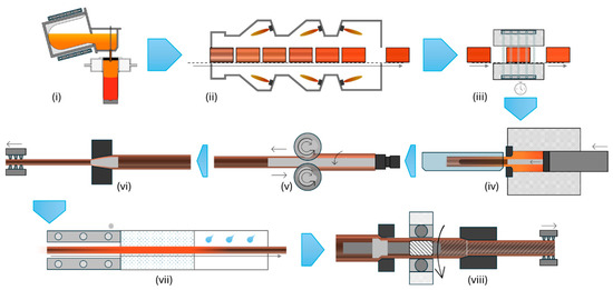
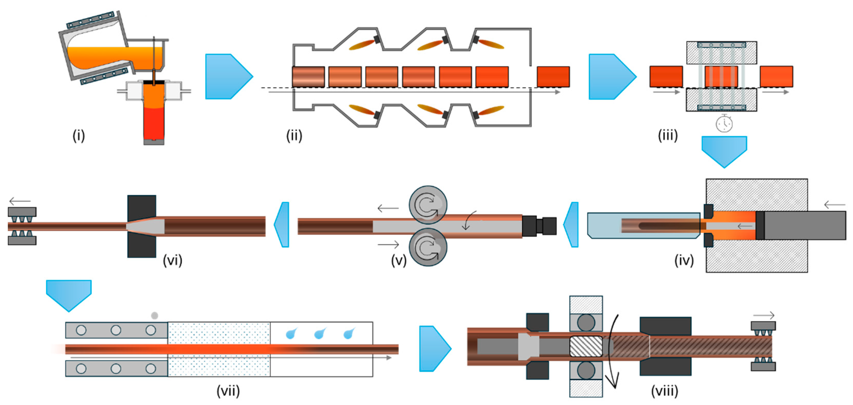
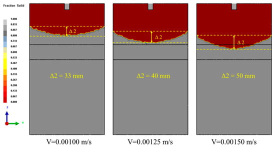
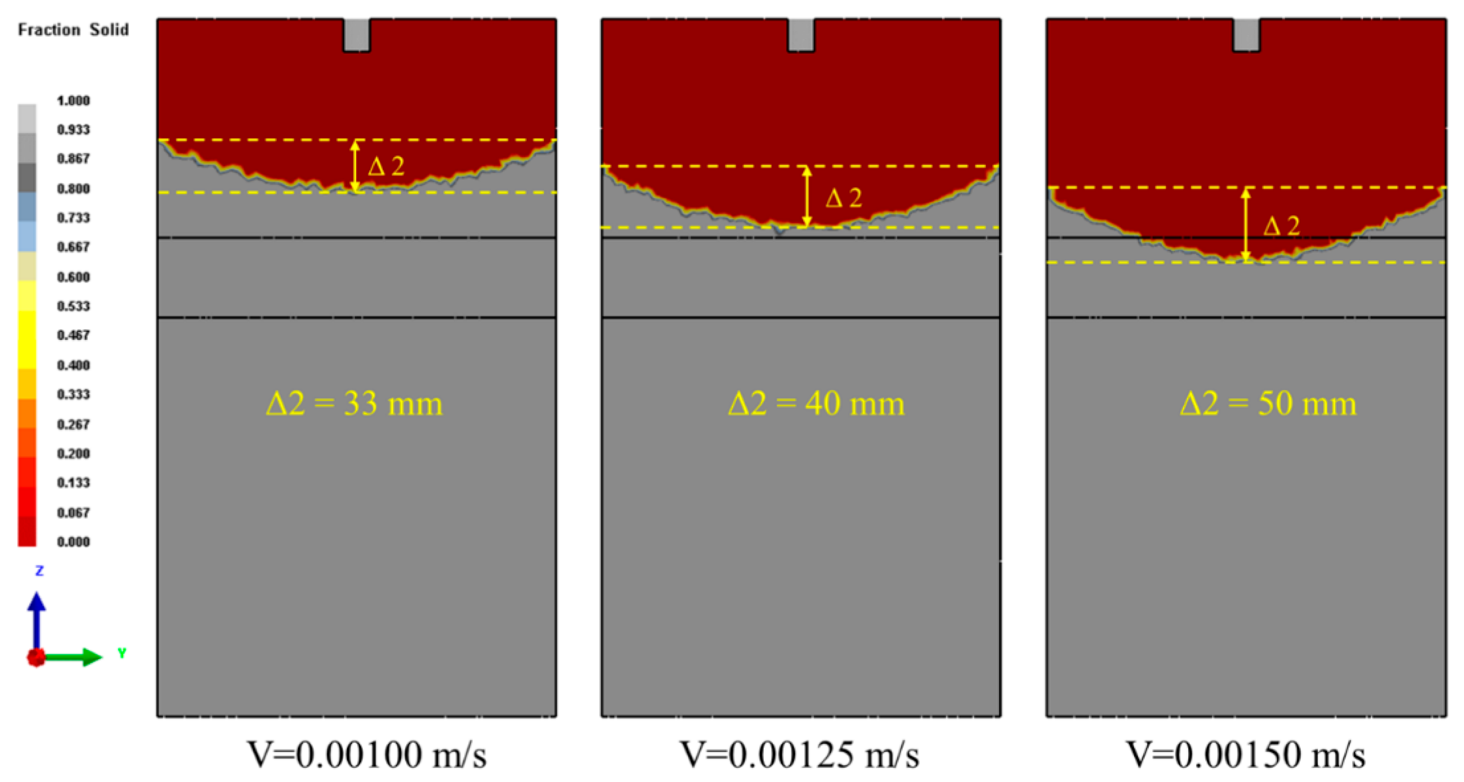
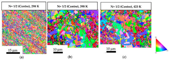
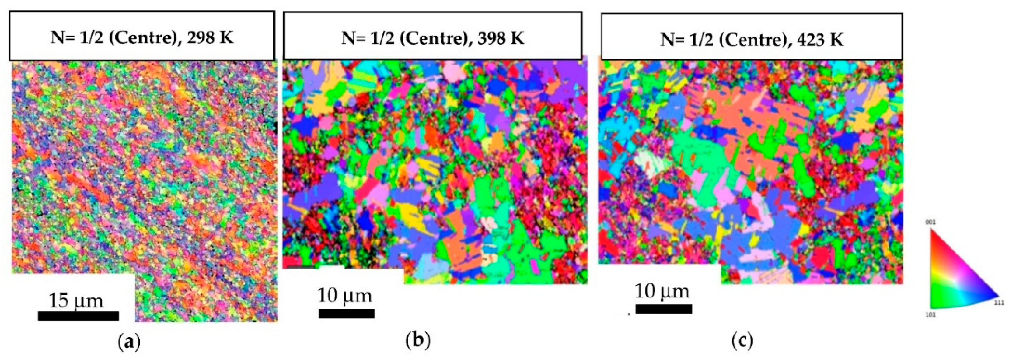
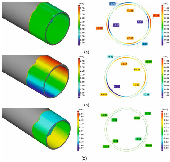
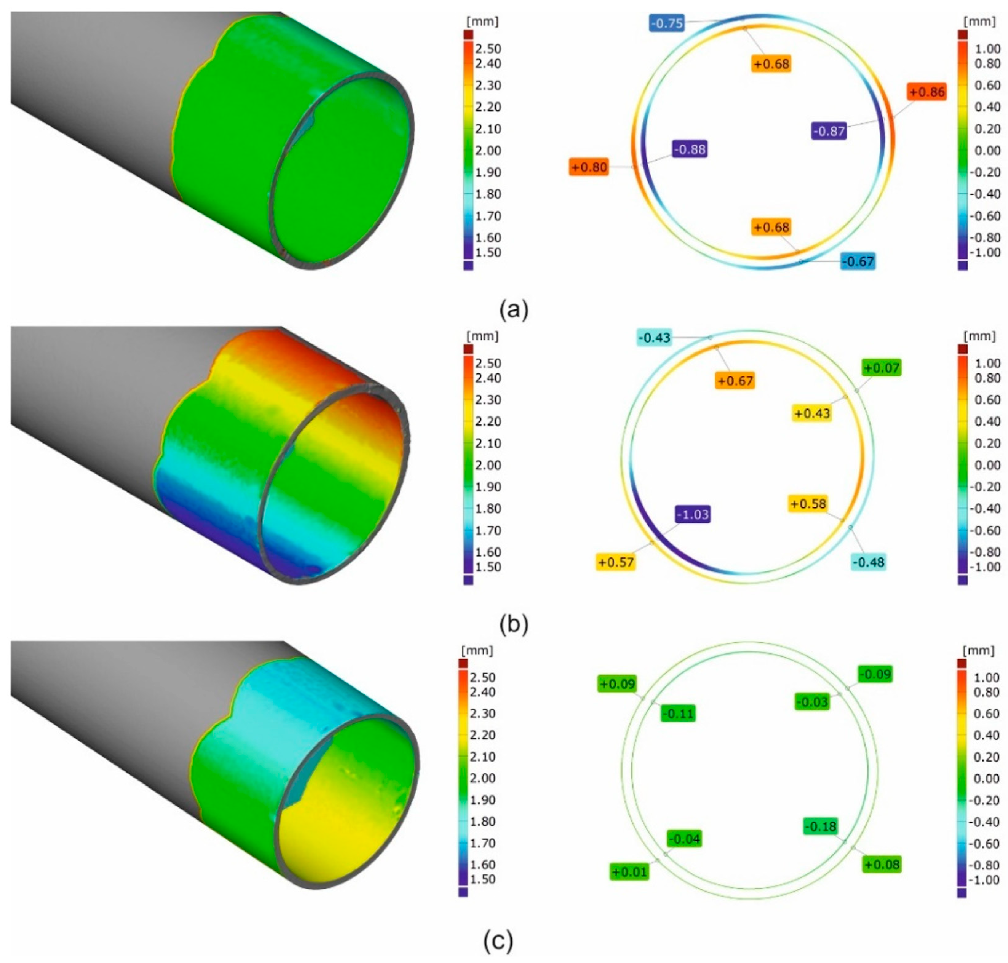
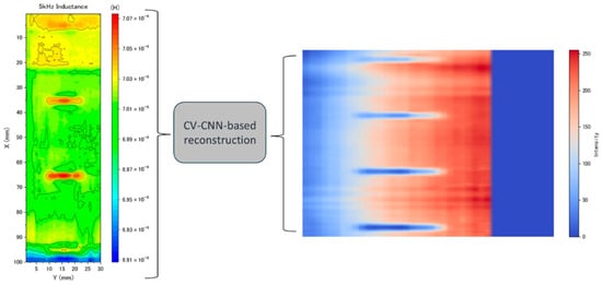
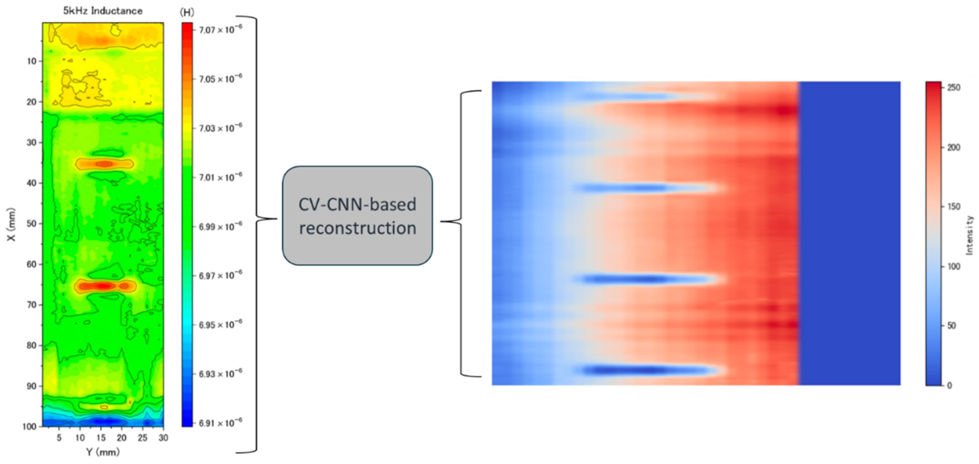
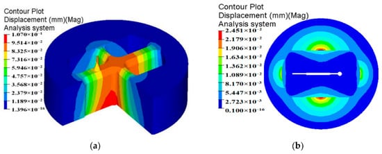
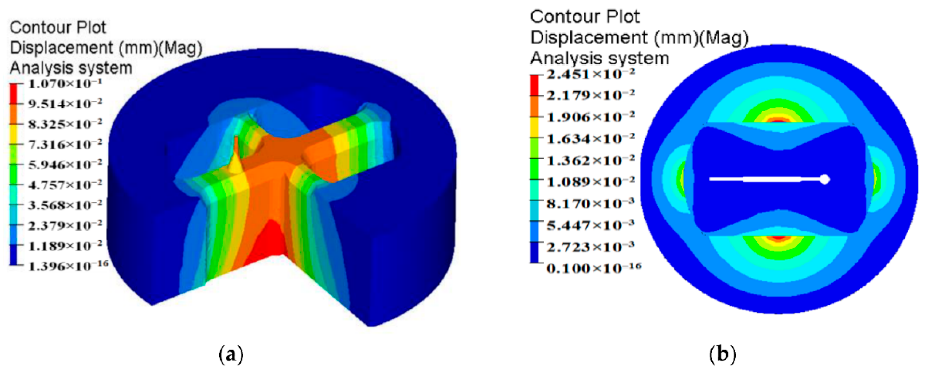
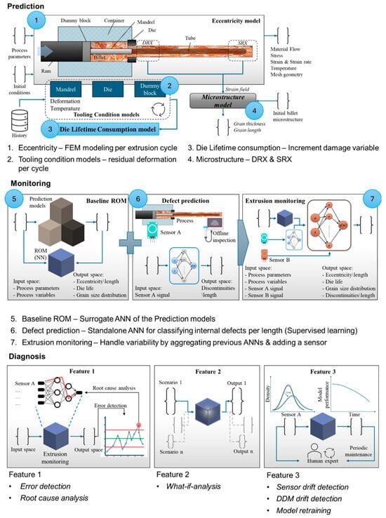
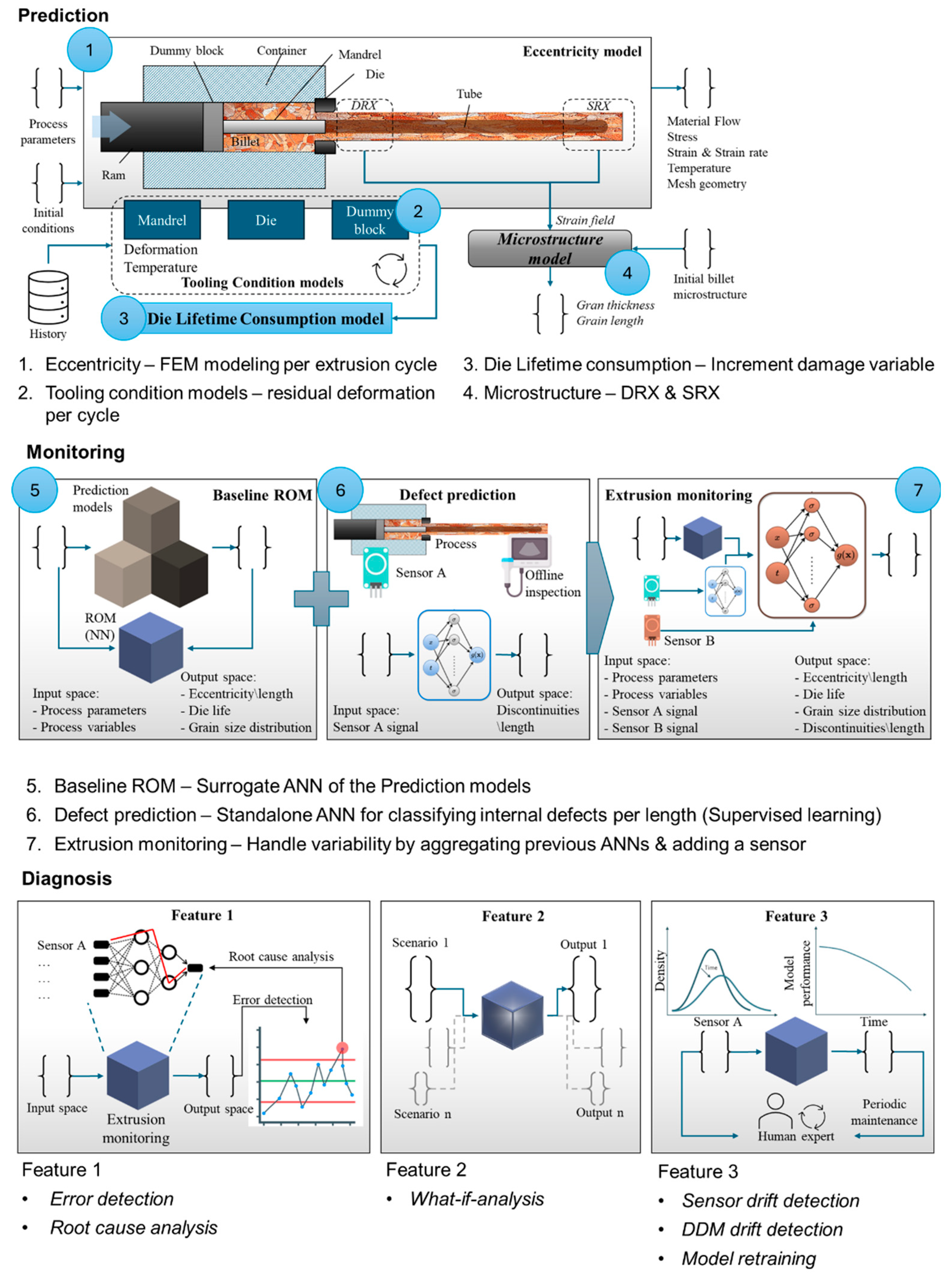

Disclaimer/Publisher’s Note: The statements, opinions and data contained in all publications are solely those of the individual author(s) and contributor(s) and not of MDPI and/or the editor(s). MDPI and/or the editor(s) disclaim responsibility for any injury to people or property resulting from any ideas, methods, instructions or products referred to in the content. |
© 2026 by the authors. Licensee MDPI, Basel, Switzerland. This article is an open access article distributed under the terms and conditions of the Creative Commons Attribution (CC BY) license.