


Abstract
Compliant mechanisms have contributed to many advances in soft robotics, and there is strong motivation to translate these ideas to assistive devices where adaptive motion at the human interface is required. This work presents novel reconfigurable compliant joints (RCJs) as a parameterized joint element for functional biomimicry in lower-extremity joints for prosthetic knees and ankle–foot orthoses, with concepts that extend to other limb joints. The RCJ uses a rigid hub and outer ring joined by an array of flexible links with centerlines defined by cubic Bézier curves. Link shapes are organized into four Bézier classes (A–D), with base types using 10, 12, or 14 uniformly distributed link slots and variants generated by modifying active-link count and distribution, forming a structured morphology space of 12 configurations for machine design. Dual-extrusion 3D-printed prototypes are characterized by a custom testing apparatus using a 2.2 kN load cell at 25 mm/s over a 0–90° rotation range across six recorded load cycles to measure torque–angle curves and stiffness under large deformations. Angle-dependent stiffness is evaluated over three fixed intervals (0–30°, 30–60°, and 60–90°) to quantify multi-stage behavior. A 2-dimensional corotational frame model and a Simscape Multibody model, including a rolling-contact knee configuration, use the same parameterization to relate geometry, nonlinear mechanics, and system-level motion. Experiments and simulations show multi-stage torque–angle profiles and predictable stiffness modulation across all configurations, with both magnitude and transition angle tunable through Bézier class and active-link distribution, positioning the RCJ as a CAD/CAE-compatible joint architecture for assistive devices or wearable robotic systems and a basis for advancing functional biomimicry in compliant mechanism design.
1. Introduction
Compliant mechanisms (CMs) are machine elements that transmit motion and force through elastic deformation rather than through traditional pin joints or bearings [1]. Embedding flexibility directly into the structure eliminates joint clearance and sliding friction, enabling high repeatability, low wear, and compact, lightweight designs with fewer parts and simpler assembly [2,3]. The same material region both guides motion and stores strain energy, so compliant mechanisms intrinsically support functions such as motion amplification, energy storage, and passive return, which are often difficult or bulky to realize with conventional rigid-body linkages [1,2]. These properties have made compliant mechanisms central to modern machine design across scales, from precision positioning stages [4,5,6] and MEMS devices to soft grippers [7], bio-inspired locomotion robots [7,8,9,10], energy-harvesting devices [11], and lower- and upper-limb exoskeletons [12,13,14]. In many of these applications, the mechanisms operate under large elastic deflections and exhibit strongly nonlinear force–displacement and torque–angle behavior, so the compliant members cannot be treated as simple small-deflection springs but must instead be designed and modeled as integral load-bearing machine elements [15,16]. Understanding how geometry, material choice, and topology shape this nonlinear behavior is therefore critical for creating reliable, efficient, and application-specific compliant systems.
1.1. Compliant Mechanisms in Machine Design
Compliant mechanisms are often grouped into fully compliant monoliths and partially compliant assemblies, and both are typically built from a small set of classic primitives such as straight or curved flexural beams (fixed–free, fixed–fixed, fixed–pinned, pinned–pinned) and flexure hinges such as simple notch hinges, corner-fileted hinges, and cross-spring pivots [2,17,18]. Fully compliant devices distribute strain throughout a continuous body, whereas partially compliant mechanisms localize bending in designated flexure regions while retaining rigid members for load transfer, alignment, and mounting [17]. Across both families, topology (how flexures and rigid members connect), geometry (shape, curvature, and dimensions), and material choice (elastic modulus, damping, fatigue behavior, print anisotropy) together determine the kinematics and load paths of the mechanism [15,17]. Over the past several decades, a rich modeling toolbox has emerged for these building blocks. For simple beams and hinges, analytical large-deflection beam theory and energy methods—often involving elliptic integrals—can approximate load–deflection behavior and equivalent stiffness [16]. At the mechanism level, design synthesis tools such as freedom and constraint topologies (FACT) [4,5], pseudo-rigid-body models (PRBM) [6,17], discrete beam element formulations, nonlinear finite element analysis (FEA), and topology optimization are routinely used to design and refine compliant devices [19,20,21,22]. More recently, multibody dynamics formulations and CAD/CAE-integrated workflows have been adopted to capture kinetostatic and dynamic response in more complex, system-level configurations [23,24,25]. These methods have been adopted in the design, optimization, and modeling of a wide range of hinges, grippers, and motion stages, but their use is still concentrated on relatively simple joint topologies and small sets of operating conditions [15,17].
Despite this progress, several challenges remain, particularly for compliant joints intended to act as tunable, load-bearing machine elements. For large deforming, spatial, or contact-aided joints, there is still no simple, intuitive way to map designer-friendly geometric parameters to target torque–angle or stiffness profiles [15,16]. The behavior of a given joint architecture is strongly influenced by large elastic deflections, geometric and material nonlinearities, and system-level constraints imposed by serial, parallel, or hybrid arrangements [15,17]. Different design philosophies, ranging from rigid-body linkages with discrete springs to fully compliant monoliths, to contact-aided and reconfigurable architectures, all come with competing trade-offs in manufacturability, tunability, and modeling complexity, and there is limited guidance on how to choose or parameterize these joints for assistive and bio-inspired applications [12,15,17]. Addressing these gaps requires parameterized geometries that can be systematically explored, along with modeling frameworks that directly relate those parameters to the nonlinear mechanical response of the joint [15,16,23].
1.2. Gaps in Bio-Inspired Joint Design for Assistive and Wearable Systems
In nature, compliance is everywhere. From the way muscles store and release energy to how fish fins or bird wings adapt their shape to the surrounding environment, biological systems rely on flexibility to move efficiently and interact smoothly. This has motivated engineers to look beyond purely rigid designs and instead build mechanisms that echo how living organisms handle motion, force, and adaptability [14,26]. In robotics, compliant elements now play a central role in creating motion that behaves more like biological movement. Soft and underactuated grippers, for instance, use flexure hinges or origami-inspired folds to conform around objects, while spatial variations in stiffness guide their closing paths [27,28]. Similar principles appear in legged and continuum robots, where distributed compliance improves energy efficiency, terrain adaptability, and safe interaction with complex environments [9,10,29]. These same ideas are increasingly being translated to wearable systems, where the goal is not only to move but to move with a human user [12,13,14].
Human joints, however, exhibit motions far more complex than those of simple hinges, and this complexity is especially pronounced in the lower limb. The knee demonstrates polycentric motion with a shifting center of rotation and coupled axial rotation during flexion and extension [30,31,32]. The ankle, though often simplified as a hinge in the sagittal plane, possesses an axis of rotation that tilts across the frontal and transverse planes and shifts dynamically due to the geometry of the talus and adjacent structures. These joints combine compliance, changing moment arms, and contact-aided kinematics to redistribute load and shape torque-angle profiles across the gait cycle. Yet many lower-limb exoskeletons, prostheses, and orthoses still rely on rigid, single-axis joints with fixed mechanical behavior. This often leads to discomfort, inefficient gait, and reduced mobility. Compliant mechanisms have recently emerged as a promising avenue to advance designs for developing more versatile robotic systems and wearable assistive technologies, including exoskeletons, prostheses, and orthoses, where generating adaptive and dynamic motion is a critical consideration for design. However, despite their numerous advantages and significant progress made in the fields of biomechanics, most assistive devices continue to rely on rigid components that inadequately replicate the adaptive behavior of human joints. There is a clear need for compact, tunable, and manufacturable joint elements whose stiffness and torque–angle behavior can be customized to the user and task.
Although compliant mechanisms and soft robotic systems have been widely studied, their translation into functional joint elements for assistive and wearable devices remains limited. Existing assistive joint designs predominantly rely on rigid-body mechanisms or discrete compliant components and do not provide a unified, geometry-driven framework for encoding and systematically tuning nonlinear torque–angle behavior within a compact, manufacturable structure. As a result, there is currently no parameterized joint architecture that directly maps geometric design variables to joint-level mechanical behavior for assistive applications.
In our prior work, as shown in Figure 1, compliant joint designs for lower-limb applications have been explored using configurations such as five-bar-based compliant knees [33], cross-hinged compliant knees [34], and rolling-contact architectures [35], all of which incorporate flexure-based rotational elements analogous to multi-flexure-hinge systems. While these designs demonstrate the feasibility of compliant joint behavior, they are inherently fixed-geometry architectures, where each configuration is tailored to a specific stiffness profile and motion characteristic. Consequently, modifying the torque–angle response or stiffness behavior requires redesigning the flexure geometry or altering the linkage topology.
Figure 1.
Previous work on the design and development of compliant knee joints for bipedal robotic applications. The top left image illustrates a five-bar-based compliant knee joint. The bottom left image shows a cross-hinged compliant knee joint configuration. The right images presents a single-piece rolling-contact knee joint designed to withstand cyclic loading, and the bottom left image shows the prototype of the bipedal robot.
The objective of this study is to develop and validate a design and modeling framework that links RCJ geometry to its nonlinear mechanical response, enabling its use as a compact, parameterized joint module for bio-inspired and assistive machines. We advance three working hypotheses: (1) Bézier-parameterized flexure arrays in a ring–hub reconfigurable compliant joint (RCJ) architecture can generate multi-stage torque–angle and stiffness profiles suitable for assistive joint design; (2) a discretized Bézier-based multibody model can predict RCJ torque–angle behavior with sufficient accuracy to support design-space exploration and morphology selection; and (3) RCJs retain useful, tunable characteristics when embedded in more complex joint constraints, such as rolling-contact mechanisms representative of lower-limb exoskeleton and prosthetic joints. The present work evaluates RCJs at the joint-module level, with emphasis on geometry-to-response behavior under controlled conditions. Direct comparison with complete prosthetic or orthotic devices will become more meaningful after system integration and application-specific validation.
2. Materials and Methods
This section first describes the RCJ architecture, design variables, and constraints, and then outlines the Bézier-based parameterization and taxonomy used throughout the study. The experimental characterization and modeling of the RCJs follow an interaction-driven design pipeline aimed at investigating functional biomimicry and bio-inspired system design for devices such as prosthetic legs, ankle–foot orthoses, and bipedal robots. The goal is to shape the mechanical outputs, which include the torque–angle profiles and relative stiffness measures for various RCJ prototypes, and map morphological design choices to task-relevant behaviors.
2.1. RCJ Architecture and Design Parameters
The RCJ is a monolithic, multi-material, partially compliant rotational joint. Its general construction consists of a rigid outer ring and a central hub made of polylactic acid (PLA), connected by a configurable array of thermoplastic polyurethane (TPU) flexible links arranged radially around the circumference. In the undeflected state, curved links span between the outer ring and inner hub without load. Under imposed rotation, the flexures act in parallel, undergoing in-plane bending and large elastic deflections about a nominal center of rotation, while the inner and outer rigid bodies provide the load path and mounting interfaces. All joints are fabricated as single integrated structures using dual-extrusion fused-filament 3D printing, which co-prints the rigid PLA and compliant TPU regions [36,37,38].
Each RCJ is defined by a set of geometry and morphology variables that are kept consistent between the CAD, fabrication, and modeling stages. At the flexure level, each link centerline is generated as a cubic Bézier curve with four control points in as shown in Figure 2. The endpoints lie on the inner hub radius and outer attachment radius , and the span angle is given by the angular separation between these endpoints as outlined in Table 1. The average flexure thickness, , and arc length, , are measured from the Bézier curve and later used in analytical formulations (Section 2.5). At the array level, the total number of uniformly spaced link slots defines the base circumferential grid. A subset of these slots is populated with active links, establishing the active link count , while the remaining unfilled slots form an inactive set used to generate variants with different link distributions. Together, these parameters govern the density and spatial distribution of the flexible link array, as well as the effective hub radius (center of rotation) and outer attachment radius (interface to surrounding structure).
Figure 2.
Design process of the reconfigurable compliant joint (RCJ). (1) Creation of a single flexible link using a Bézier spline between the inner and outer rings, (2) circular replication of the link using the Rotate Sketch feature to form the full structure, and (3) final 3D model of the RCJ assembled in SolidWorks 2020 SP5.0.
Table 1.
General RCJ design parameters.
The RCJ morphologies studied here are organized into Bézier link classes (A–D), where each class corresponds to a distinct centerline shape generated by a specific set of Bézier control points as outlined in Figure 3. Classes A, B, and C serve as base types, each constructed from uniformly spaced arrays of 10, 12, and 14 link slots, respectively. Within a given class, the control points and material-process parameters (PLA for rigid regions, TPU for compliant links, print settings) are held constant, and variants are created solely by altering the active-link count and slot pattern. This design strategy isolates the influence of link number and distribution on stiffness and torque–angle behavior.
Figure 3.
RCJ morphology chart featuring bases and variants. The left panel shows the Class A, Class B, and Class C variants that are uniformly distributed, and the right panel shows the variants of joints where the flexures are omitted selectively.
RCJ configurations are grouped into classes, where each class represents a family of morphologies defined by a specific Bézier spline-shape geometry. Within a given class, one or more base types serve as the foundational configurations. These base types consist of a uniformly spaced array of flexible links arranged around the central hub, and they define the “full” circumferential layout from which variants are derived. In this study, Class A, Class B, and Class C correspond to base types constructed with 10, 12, and 14 link slots, respectively. These base configurations represent complete, uniformly distributed forms of each class and serve as reference geometries for both modeling and experimentation. Starting from each base type, additional RCJ variants are generated by modifying the distribution of active-links within the original slot array. Variants are produced by selectively omitting one or more flexures, thereby changing the total number of active elements while preserving the underlying Bézier link shape of the class. For example, the 12-slot base layout consists of slots numbered 1–12. A derived configuration that deactivates slots {5, 6, 7, 8} yields an active-link count of 8 and thus defines an RCJ variant that shares the Class A link geometry but exhibits different load distribution and stiffness. Keeping the link geometry, material, and print process fixed while varying only the active-link pattern isolates the influence of morphology on torque–angle behavior and stiffness.
A simple naming convention is used to identify each RCJ morphology and to preserve lineage between families and derived configurations (Figure 3). Each joint is labeled using the format [Class]-[Type]-[N], where class denotes the Bézier shape family (A–D), type identifies whether the configuration is a uniform base (U) or variant (X#), and N gives the number of compliant links in the array. For example, A-U-10, A-U-12, and A-U-14 represent Class A uniform bases with 10, 12, and 14 links, respectively, while A-X1-6 and A-X2-9 indicate Class A variants (Variant 1 and Variant 2) with 6 and 9 active links. This compact label makes it possible to compare torque–angle behavior across classes while also isolating the effects of link count and distribution within a given Bézier family, supporting systematic morphology-to-function analysis for joint design.
2.2. Bézier-Based Geometric Parameterization
Each RCJ flexure is described by a cubic Bézier curve, which defines the link centerline in Cartesian space. A cubic Bézier curve is specified by four control points as illustrated in Figure 1, and its position vector is given by
The endpoints and lie on the inner hub radius and outer attachment radius , respectively, so that the span angle is determined by the angular separation of these points. The intermediate control points , shape the control polygon and thereby govern the end tangents and mid-span curvature of the flexure. Adjusting these points in CAD allows the designer to tune the local curvature, end-slope conditions, and overall arc length of the flexure.
Cubic Bézier curves were selected because they provide a useful balance between geometric flexibility and a compact, manageable set of design variables for RCJ design. For the present study, the flexure representation needed to satisfy several requirements at once. It had to be expressive enough to generate distinct morphologies, compact enough to support systematic comparison across a registry of designs, intuitive enough for direct manipulation in CAD, and smooth enough to support energy-based and multibody modeling. The cubic Bézier form satisfies these requirements with only four control points, allowing direct control of endpoint position, end tangents, and mid-span curvature while preserving a low-dimensional and interpretable geometric representation. Bézier-generated profiles have also been used previously in the mathematical modeling of compliant mechanisms with non-standard notch geometries and have been shown to support closed-form or semi-analytical compliance formulations. For example, Wang et al. developed curvature-adjustable multiple-axis hinges using piecewise Bézier-line-Bézier profiles and derived six-degree-of-freedom analytical compliance relations using Castigliano’s theorem, with validation against finite element analysis showing maximum errors on the order of 6% [39,40]. These studies support the use of Bézier-based parameterization in compliant mechanism analysis and motivate its use here for RCJ spline geometries, where a smooth, compact, and transferable geometric description is needed for both energy-based modeling and multibody simulation.
This representation also supports continuity across the design workflow. The same control points used to sketch the flexures in CAD are passed directly into the MATLAB/Simscape modeling pipeline, so the simulated link geometry corresponds directly to the manufactured prototype without additional curve fitting, remeshing, or geometric re-parameterization. This continuity is especially important in the present work because the objective is not only to define a single compliant link, but to establish a structured RCJ morphology space that can be generated, compared, and eventually used in inverse design studies.
2.3. Prototype Fabrication via Dual-Extrusion FFF
All RCJ prototypes were fabricated using dual-extrusion fused-filament fabrication (FFF) on an Ultimaker S-series 3D printer. This process integrates rigid and compliant regions in a single continuous build, ensuring structural and geometric continuity at material interfaces. The rigid frame, consisting of the inner hub and outer ring, is printed from PLA, while the flexible links are printed from TPU-95A. By co-printing both materials, the need for post-assembly bonding or mechanical fasteners is eliminated, avoiding alignment errors and stress concentrations that could alter the intended deformation. A standardized slicing profile was used for all builds in Ultimaker Cura to minimize process-related variability and isolate the effects of geometry and morphology on mechanical performance. Parameters such as layer height, infill pattern and density, extrusion temperature, and print speed were kept constant across all specimens. In a typical build, a 0.1 mm layer height, 100% gyroid infill, and material-specific print speeds were used, as summarized in Table 2. The extrusion sequence was configured so that PLA regions were deposited first, followed immediately by TPU deposition. This sequencing promotes strong interfacial adhesion and reduces thermal distortion at the PLA-TPU boundary. All RCJs were printed in a flat orientation, with the flexible link centerlines lying in the plane of the build platform. This orientation was chosen with the primary bending direction aligned with the layer stacking direction to improve consistency of layer bonding along the plane of bending and to reduce out-of-plane warping. It also mitigates print-induced anisotropy that could otherwise affect stiffness, yield behavior, and cycle-to-cycle repeatability.
Table 2.
Standard printing parameters for RCJ prototypes.
After fabrication, each specimen underwent visual and dimensional inspection to verify conformity with the CAD geometry. Measurements were taken at multiple locations on the hub, ring, and link regions to confirm dimensional tolerances and surface quality. Specimens exhibiting deviations beyond the established thresholds, ±0.15 mm for rigid PLA regions and ±0.25 mm for compliant TPU segments, were discarded. Accepted RCJs were cataloged by class, base type, and variant designation, then prepared for experimental testing. This fabrication protocol produced consistent physical prototypes of the intended RCJ morphologies, ensured reproducibility across multiple builds, and enabled the modeled geometries to be translated directly from CAD into testable compliant mechanisms.
PLA and TPU-95A were selected as a fabrication-compatible rigid/compliant material pair that enabled repeatable dual-extrusion printing of the RCJ architecture across multiple morphologies. In the present study, these materials serve primarily as a proof-of-concept prototyping platform for establishing the RCJ geometry-to-response framework rather than as a finalized material system for assistive-device deployment. The material property values used in the present study were taken from the manufacturer’s datasheets for the PLA and TPU-95A filaments [36,37]. For assistive-device applications, the RCJ geometry can be implemented using reinforced additive manufacturing (e.g., carbon-fiber-reinforced polymers) or injection molding, enabling higher strength, improved durability, and consistent material behavior while preserving the geometry-driven compliance design.
2.4. Experimental Setups
All RCJ configurations in the registry were experimentally tested to obtain torque–angle measurements under central rotation, and morphology D-X1-3 was additionally evaluated in a rolling-contact leg testbed. Test parameters, including sampling rate, actuation velocity, cycle count, and averaging procedures, were kept constant within each campaign and are summarized in Table 3.
Table 3.
Experimental testing parameters.
2.4.1. Central-Rotation Test
Load–deflection tests were conducted using a custom-built apparatus integrated with a Mark-10 F505-IM test frame equipped with a 2.2 kN load cell and IntelliMESUR software. Linear crosshead motion was converted into hub rotation through a rack-spur gear transmission. The frame’s vertical displacement served as the drive variable, while the inline force sensor measured the load transmitted through the joint. The experimental setup is shown in Figure 4.
Figure 4.
Experimental setup used to characterize the mechanical response of the RCJ. The setup integrates a uniaxial force testing machine, a custom-built test apparatus, and a CAD representation of the apparatus showing the rack-spur gear transmission and RCJ integration.
Prior to testing, each RCJ configuration was inspected, labeled, and measured for key dimensions. The joint was mounted through the outer ring’s bolt pattern, and the hub was connected to the rack-gear drive using a keyed coupler so that crosshead travel produced rotation about the hub center. Force and displacement channels were zeroed in the unloaded state. For each specimen, the programmed stroke was executed at a constant rate of 25 mm/s, beginning with one settling cycle to seat the interfaces, followed by six recorded cycles. Each cycle consisted of a 29.2 mm extension (corresponding to 90° clockwise rotation) and a 29.2 mm retraction (90° return), yielding a full 180° traversal per cycle without contacting mechanical end stops.
Repeatability was addressed through standardized mounting, one settling cycle followed by six recorded cycles per configuration, channel zeroing before each test, and rejection of runs with obvious setup irregularities. Tests were repeated or discarded if mounting loosened, if the force signal approached the sensor limit, or if stroke limits were reached prematurely. The repeated-loading protocol used here supports short-term characterization of response consistency but does not yet constitute a long-horizon fatigue or durability assessment. Within the six recorded cycles, no catastrophic degradation was observed for accepted runs, and the measured response remained sufficiently consistent for cycle-averaged comparison across configurations.
Time, force, and displacement were recorded for each run. Angular rotation was derived from displacement using the 58.4 mm-per-revolution calibration, and torque was computed from the measured force and the moment arm of the rack-to-hub transmission. Tests were repeated or discarded if mounting loosened, if the force signal approached the sensor limit, if stroke limits were reached prematurely, or if visible damage developed in the links. Stiffness was computed in two forms for comparison with analytical and numerical models. An initial stiffness was estimated from the small-angle region near zero rotation using the cycle-averaged torque–angle curve, while stiffness values throughout the full rotation were obtained from the geometry-based parameterization of the same configuration. Angle-dependent stiffness was evaluated over defined intervals across the motion range (for example, 0–30°, 30–60°, 60–90°), allowing for direct comparison between measured and modeled stiffness evolution as the links deform under rotation.
2.4.2. Rolling-Contact Knee Testbed
To evaluate RCJ behavior under more realistic joint kinematics, a rolling-contact case study was carried out using a single-leg testbed as illustrated in Figure 5. The rolling-contact configuration was introduced as a mechanically representative, bio-inspired test environment for evaluating RCJ behavior. The human knee exhibits polycentric motion with a shifting instantaneous center of rotation and coupled axial rotation during flexion and extension. By enforcing contact between auxiliary circular profiles, the mechanism produces a migrating center of rotation that captures this important qualitative feature of knee-like motion. The purpose of this configuration is to examine how RCJ morphology behaves when subjected to coupled rotation and translation. The platform consists of a thigh (upper segment) and calf (lower segment) joined by a rolling-contact mechanism that produces knee-like flexion–extension. RCJ morphology D-X1-3 is mounted on each side of the leg assembly. For each RCJ, the inner hub is fixed to the thigh segment, while the outer ring is fixed to the calf using the mounting features. The knee linkage is actuated by a slider-crank mechanism, which drives repeatable flexion–extension cycles with controlled amplitude and rate. This arrangement facilitates consistency and allows for a direct comparison with the central-rotation bench tests, where the hub rotates about a fixed center. The rolling-contact pair consists of two disks connected by a rigid link whose length equals the sum of their radii, producing near-pure rolling with minimal, but repeatable, slip. This geometry allows the RCJ hub center to translate relative to the leg segments, approximating the moving instantaneous center of rotation characteristic of human tibiofemoral motion.
Figure 5.
Experimental platform for the bio-inspired rolling-contact knee mechanism with integrated RCJ module. The CAD model shows the segment geometry, physical dimensions, compliant foot, and slider-crank actuation used to drive the system. The inset highlights the rolling-contact knee mechanism and RCJ integration. The physical prototype is shown in undeformed and deformed configurations, with 6-DoF Viper sensors used to track motion during testing.
In this testbed, data collection focuses on kinematics rather than direct force measurement. The rigid-body motion of the thigh, shank, and RCJ hub is tracked using three 6-DoF Viper sensors. Marker placement enables recovery of the hub-center trajectory and computation of the knee angle from the relative motion of the two segments. Synchronized images are recorded to capture the deformation of the link array throughout each cycle. Kinematic processing involves establishing a global reference frame, registering sensor data, computing knee angle and hub-center trajectories, and resampling the data onto a common angular grid for comparison with both model predictions and bench-test torque–angle curves. Filtering is minimal, limited to the removal of transient spikes, and no smoothing is applied that would distort motion paths. Comparing the central-rotation and rolling-contact results demonstrates how the constraint environment alters the apparent mechanical behavior of the same 3-link RCJ and highlights its role as a functional element within a larger bio-inspired limb system rather than as an isolated component.
2.5. Modeling Framework
Simulating the RCJs requires capturing both large geometric deflections and the elastic response of the flexible links while the surrounding structure behaves as a rigid multibody system. Conventional finite element tools can accurately resolve local deformation but are less convenient for repeated, system-level studies that couple joint flexibility with mechanism kinematics. To address this, a hybrid approach is used, where each flexure centerline is represented by a cubic Bézier curve (Section 2.2), which is then discretized into a chain of rigid segments connected by rotational springs. This discretized representation is implemented in MATLAB and SimScape Multibody to enable parameterized, system-level simulations that mirror the experimental configurations as illustrated in Figure 6.
Figure 6.
Workflow for translating RCJ geometry into system-level simulations.
2.5.1. Bezier Discretization and Compliance Representation
As described in Section 2.2, the centerline of each flexible link is defined by a cubic Bézier curve , parameterized by four control points . To construct a mechanical model suitable for multibody simulation, this continuous curve is discretized into segments. A custom MATLAB function samples at uniformly spaced parameter values , producing a sequence of node coordinates . Each pair of adjacent nodes defines a rigid segment of length and orientation angle in the plane. The flexible link is then modeled as a planar chain of rigid bodies connected by rotational springs. At each interior node, a torsional spring with stiffness represents the local bending compliance inferred from the link geometry and material properties. Under small-strain, large-rotation assumptions, the flexure is treated as a prismatic beam of uniform thickness , width , and Young’s modulus , loaded in-plane strain/plane stress bending. The local stiffness values are obtained from Euler–Bernoulli beam theory applied to each segment, using the segment length and an effective area moment of inertia consistent with the printed cross-section. This approach concentrates curvature at the interior joints while maintaining a continuous geometric description of the centerline.
To more accurately capture large rotations with small but finite strains, a corotational 2D frame formulation is used at the element level. In this approach, each discretized segment is associated with a local frame that “follows” the current orientation of the element. The element stiffness is first assembled in the local frame using the standard linear Euler–Bernoulli frame stiffness matrix , expressed in terms of axial and bending DOFs. A corotational transformation matrix maps nodal displacements and forces between the global and local frames, and the corresponding global element stiffness is given by
Because is updated as the element rotates, large rigid-body rotations are handled geometrically, while the strain within each element remains small and is governed by the linear local law. The global stiffness matrix for the link is assembled from all and solved iteratively under the applied boundary conditions, yielding nodal displacements and reaction forces. This corotational frame formulation is used both to verify the lumped torsional-spring approximation and to generate reference torque–angle curves for selected configurations. The discretized chain is embedded in a 2D model subject to the following assumptions: (i) deformations remain in the plane of the printed links; (ii) material response is linear elastic with constant ; (iii) shear deformation is neglected at the segment level, with bending dominating the compliance; and (iv) large rotations are captured through the multibody kinematics and corotational transformations, while strains within each segment remain small. These assumptions are consistent with the experimental loading conditions, where flexures undergo large angular deflections but do not approach material yield.
Geometric and mechanical data such as node coordinates, segment lengths, and tangent angles are exported directly from the Bézier discretization function into the SimScape environment. Each segment becomes a rigid body in SimScape Multibody, and each interior node becomes a revolute joint with the corresponding stiffness . The inner hub and outer ring of the RCJ are modeled as rigid bodies attached to the ends of the flexure chain, reproducing the printed geometry and boundary conditions. This construction preserves the curvature dictated by the original Bézier profile while enabling stable simulation of large-deflection behavior under both centrally driven rotation and rolling-contact constraints. Among the available configurations, the symmetric 3-link, D-X1-3, morphology plays a special role in the modeling framework. With three uniformly spaced links at 120° intervals, this morphology provides a convenient reference case, where its radial symmetry simplifies the distribution of strain energy, reduces coupling between bending modes, and improves numerical stability when studying large deflections and hub translation. The same discretization and compliance representation are applied to all other classes and variants, allowing direct comparison of how changes in link number and distribution alter the simulated torque–angle and stiffness response.
The model parameters were defined from the RCJ geometry, assumed material properties, and measured characteristics of the test apparatus. Flexure geometry, including the Bézier-defined centerlines and the hub and outer-ring dimensions, was taken directly from the CAD models used for prototype fabrication. The compliance terms were then computed from this geometry using beam-theory-based relations together with material property values for PLA and TPU-95A obtained from manufacturer datasheets and standard reference values. In addition, the relationship between rack displacement and hub rotation was based on the rack-and-pinion geometry of the test setup and confirmed through direct measurement. Hysteresis, damping, and nonlinear constitutive behavior were intentionally excluded from the present forward-design model so that geometry-driven trends across the RCJ registry could be isolated more clearly. The resulting formulation should therefore be interpreted as a linear-elastic, geometry-driven approximation of RCJ behavior rather than a full viscoelastic material model. The present approach is most valid for large-rotation, in-plane compliant behavior with moderate local strains. Accuracy decreases when deformation involves strong material nonlinearity, out-of-plane effects, local damage, or geometric interference between links and surrounding features. The framework is intended as a system-level design model within this range.
2.5.2. SimScape Multibody Model: Central RCJ
Conventional FEA tools such as ANSYS and SolidWorks Simulation can capture local deformation under prescribed loads, but they are less convenient for repeated, system-level studies that couple compliant joint deformation with rigid-body dynamics and actuation. For this reason, MATLAB Simscape Multibody was selected as the primary simulation environment. Simscape physical modeling library within Simulink supports multi-domain systems, while Simscape Multibody provides 3D visualization and parameterized joints that can be driven with inputs matching experimental conditions. In the central-rotation model, the RCJ is represented by three main subsystems: (i) the discretized spline network defining each compliant element, (ii) the rigid-body components forming the inner and outer rings and drive hardware, and (iii) the actuation and sensing assemblies. The Bézier curve function described in Section 2.5.1 reconstructs each flexure as a chain of rigid segments with intermediate rotational springs. This function outputs segment lengths, initial orientations, and node coordinates, which are imported into Simscape to build the flexure chain. To approximate the experimental test apparatus, three identical flexure chains are created and connected between an inner circular body (hub) and an outer circular body (ring), with angular offsets derived from the Bézier function to match the printed geometry. The inner and outer circles, along with the rack-and-pinion, are assembled using standard Simscape Multibody blocks. The outer ring is fixed to the global reference frame, while the pinion gear is rigidly attached to the inner hub, reproducing the central axis of rotation used in the bench tests. The MATLAB Simscape model and RCJ initial and deformed configurations are shown in Figure 7.
Figure 7.
Illustration of MATLAB Simscape Multibody model of three spline RCJ under central rotation. The top section shows the Simscape drive chain, with the left being the input, the center being the joint and rigid rack-spur generation, and the right being the output variables exported from the simulation. The image also shows a three-spline (D-X1-3) RCJ generated using Bézier control points and simulation results from MATLAB Simscape R2024b when the central axis is rotated by .
Actuation is applied through a prismatic joint driving the rack with a triangular displacement waveform: a pair of ramp signals generates a linear increase in displacement from zero to a specified maximum, followed by a linear return to zero. This motion produces forward and reverse rack travel that, through the gear constraint, generates hub rotation equivalent to the 90°–0°–90° cycles used experimentally. During each simulation, the model records torque at the hub revolute joint, angular displacement of the hub, and nodal positions along one representative spline. These outputs support quantitative comparison with measured torque–angle curves and qualitative comparison of deformation shapes captured in the experiment.
2.5.3. SimScape Multibody Model: Rolling-Contact Configuration
A second SimScape model is used to study RCJ behavior when integrated into a rolling-contact mechanism representative of a robotic knee. This model reuses the same discretized spline subsystems and their connections to the inner and outer disks but replaces the rack-and-pinion drive with a kinematic chain that enforces approximate rolling-contact between two circular bodies.
In this configuration, the RCJ hub is attached to an inner disk representing the proximal segment (thigh), and the outer ring is attached to a second disk representing the distal segment (calf). The outer spline disk is then actuated around the central disk using two auxiliary circular bodies connected by a rigid bar whose length equals the sum of their radii. As the lower auxiliary circle rotates about the upper one, the contact constraint and link length produce a motion pattern that closely approximates rolling with small, repeatable slip, like the rolling-contact behavior observed in the physical knee mechanism.
The RCJ is thus placed directly in the load path between the two limb segments, and its deformation is driven by the relative motion of the rolling-contact pair. Sensors in the SimScape model record the relative rotation between the thigh and shank disks (effective knee angle), the translation of the RCJ hub, and the internal joint variables associated with the flexure chains. Comparing these kinematic quantities and the corresponding torque response with central-rotation simulations and experimental data highlights how the constraint environment—fixed-center versus rolling-contact—changes the apparent behavior of the same 3-link RCJ. This rolling-contact model provides a bridge between bench-top characterization and bio-inspired leg kinematics.
3. Results
Across all tested RCJ configurations, the measured torque–angle response exhibited a consistent nonlinear, multi-stage profile during loading to large rotations (up to 90° in the central-rotation bench tests). The reported torque–angle curves are based on cycle-averaged results from the six recorded cycles for each configuration. Standard deviation across cycles and representative coefficients of variation were used to assess short-term repeatability of the measured response. These measures provide a quantitative indication of consistency within the present results. In general, torque increased rapidly at small angles, transitioned through one or more mid-range slope changes, and then approached a higher-angle regime that could be either gradually stiffening or closer to saturation depending on class morphology and active-link distribution. This “stage structure” is central to the RCJ concept as a functional biomimicry element. Rather than behaving like a single linear torsional spring, the RCJ produces an angle-dependent mechanical response that can be shaped through geometry (Bézier class) and morphology (link count and distribution).
3.1. Central-Rotation Characterization
To support comparisons and interpretability, stiffness was evaluated over fixed rotation intervals, and the same color mapping was used consistently across torque–angle plots and deformation-shape plots. The interval colors correspond to 0–30° (magenta), 30–60° (blue), and 60–90° (green). This demonstrates how the stiffness changes in torque–angle evolve with the deformation behavior observed across the same angular windows.
3.1.1. Repeatability and Quantitative Validation
Repeated-cycle testing was used to evaluate short-term repeatability of the central-rotation response, and a representative shape-comparison metric was used to assess model-experiment agreement in deformation. For each RCJ configuration, one initial preload cycle was performed before the recorded trials to minimize seating and mounting effects. The reported torque–angle curves were then computed from the subsequent five cycles using a common angular basis to obtain the mean response and cycle-to-cycle variation. Repeatability was summarized using the cycle range, standard deviation, and representative metrics, including peak torque and torque at selected angles, as shown in Table 4. For deformation validation, the D-X1-3 single-link case at 90° rotation was compared through registration of the experimentally extracted and model-predicted centerline shapes, and the resulting pointwise residuals gave an RMSE of 0.373 mm, as shown in Figure 8. These results provide quantitative support for both repeatability of the measured response and agreement between the simulated and observed deformation.
Table 4.
Repeatability and quantitative comparison metrics for representative cases.
Figure 8.
Repeatability and quantitative deformation validation for representative RCJ cases. (a) Five-cycle torque–angle response of A-X4-10 under central rotation, shown with the mean response and cycle range. (b) Registered comparison between simulated and experimentally extracted D-X1-3 single-link shapes at 90° rotation, with pointwise residuals and an RMSE of 0.373 mm.
3.1.2. Torque–Angle Response of Uniform Base Morphologies
The uniform base morphologies (A-U-10, A-U-12, A-U-14; B-U-10, B-U-12, B-U-14; C-U-10, C-U-12, C-U-14) establish how each Bézier class behaves when links are uniformly distributed around the circumference and the active-link set is maximally regular (Figure 3, left panel). Several common trends were observed.
First, increasing the number of uniformly distributed links generally increased the torque capacity across the motion range, as shown in Figure 9. This effect was most evident in the mid-to-high angle regime (30–90°), where additional links increased the number of parallel load paths and reduced the tendency for any one region of the array to dominate the strain energy. Second, within each class, the early-angle region (0–30°) was comparatively more sensitive to link shape (class) than to link count, suggesting that the onset stiffness is strongly influenced by the initial curvature distribution and end-tangent geometry set by the Bézier control points. Third, the transition between intervals, visible as changes in slope, shifted in angle and magnitude across classes, indicating that different link geometries can be used to place “stiffness transitions” at different portions of the motion. Taken together, the base-morphology results establish that the RCJ architecture supports a tunable family of torque–angle profiles spanning both magnitude scaling (via link count) and qualitative reshaping (via link geometry class).
Figure 9.
Uniform base classes (A, B, C) torque–angle response for 10, 12, and 14 flexible links and class average shown in black.
3.1.3. Torque–Angle Response of Variant Morphologies
Variants were generated by holding the Bézier class fixed while altering the active-link count and the spatial pattern of active vs. inactive slots (Section 2.1). The experimental torque–angle curves for the variants (Figure 3, right panel) show that redistribution of the same link geometry can significantly reshape the response even at similar active-link counts. Please see Figure 10. Two distribution-driven effects were consistently observed. First, variants that concentrate active links into fewer regions of the circumference tended to exhibit earlier onset of steeper stiffness growth, reflecting earlier engagement of a subset of links that experience higher curvature demands under rotation. Second, variants that maintain a more balanced distribution of active links tended to produce smoother torque–angle growth with reduced “knee-like” changes in slope, indicating more even load sharing and a more gradual evolution of deformation modes.
Figure 10.
Torque–angle response for Class A and Class B RCJ variants. Measured torque is plotted versus joint angle over a 0–90° sweep for Class A (top row) and Class B (bottom row) variants. Colored segments indicate angle intervals 0–30°, 30–60°, and 60–90° to highlight changes in stiffness progression across the sweep.
These findings are important because biological joint behavior is not only about stiffness magnitude, but also about when and how stiffness changes across motion. The RCJ variant results demonstrate that these timing features can be shifted through morphology alone, without changing material, print parameters, or the underlying link curve family.
3.1.4. Interval Stiffness and Multi-Stage Behavior
Angle-dependent stiffness was computed from the cycle-averaged torque–angle curves over defined intervals (0–30°, 30–60°, 60–90°) to quantify the multi-stage behavior implied by the curve shapes. Across classes and configurations, stiffness was not constant with angle; instead, it exhibited distinct regimes aligned with the interval coloring used in the plots. In this study, predictable stiffness modulation refers to systematic geometry-dependent shifts in interval-based stiffness behavior across the RCJ registry. Interval-averaged stiffness values provide the primary quantitative descriptor of these shifts, allowing comparison of how Bézier class, link count, and link distribution alter both the magnitude and timing of stiffness changes across motion.
In several configurations, the largest stiffness increase occurred in the 30–60° interval, suggesting a transition where deformation localizes into higher-curvature regions of the links or where additional links become effectively engaged as the hub rotates. In other cases, the response was closer to monotonic stiffening across all intervals, which is desirable when the design objective is a smooth increase in resistive torque rather than a distinct stiffness transition. This interval-based stiffness view provides a compact “behavior signature” for each morphology and is suitable for comparing candidate RCJs against target joint profiles used in assistive devices (e.g., gait-phase-specific stiffness expectations).
The interval-based stiffness signatures reported here are intended as a first step toward future comparison with gait-phase-specific human moment–angle or quasi-stiffness data. Direct one-to-one quantitative matching to specific human knee or ankle datasets will require additional scaling, loading normalization, and application-specific validation in future studies.
3.1.5. Deformation Behavior and Model-Experiment Comparison
The 2D corotational frame model (Section 2.5.1) was used to predict deformation and torque–angle behavior using the same Bézier control-point parameterization as CAD. For selected configurations, the model reproduced the qualitative features observed experimentally: (i) nonlinear stiffening with rotation, (ii) stage-like slope changes aligned with deformation transitions, and (iii) sensitivity of the early-angle response to link geometry class. Deformation-shape evolution provides the physical interpretation of why multi-stage stiffness arises, as seen in Figure 11. For each class, flexure centerlines progressed through visibly different configurations across the angle intervals. The interval-colored deformation overlays indicate that early rotations (0–30°) generally involve relatively distributed bending with modest curvature amplification, while mid rotations (30–60°) often show stronger curvature localization and more pronounced shape change. The latter interval (60–90°) typically shows either continued curvature growth in already-localized regions or an apparent geometric “reorientation” where the effective lever arm and curvature distribution change.
Figure 11.
MATLAB 2D corotational frame model results showing the single link deformation plots across Bezier classes.
In deformation comparisons, the model captured the overall shape trends observed across the angle intervals, particularly the transition from distributed bending at low angles to localized high-curvature regions at mid-to-high angles (Figure 8). Remaining discrepancies are expected under the current assumptions (linear elastic material law for TPU, neglect of shear deformation, simplified cross-section representation, and idealized boundary conditions at the hub–link and ring–link interfaces). Nonetheless, the corotational model provided a computationally efficient forward-design tool for exploring morphology changes and interpreting stage behavior through strain-energy distribution and curvature localization. A representative example is shown for D-X1-3 (Figure 12), where deformation overlays demonstrate substantial shape change aligned with the same angle intervals used in the torque–angle plot. This alignment supports the interpretation that the RCJ’s torque–angle structure is not an artifact of the measurement method, but a direct consequence of geometry-driven deformation-mode evolution in the flexible link array.
Figure 12.
Rolling-contact experimental results and model comparison for the D-X1-3 RCJ configuration. Left: Measured torque–angle response and MATLAB 2D deformation evolution for D-X1-3. Right: Undeformed and deformed prototype configurations, SimScape Multibody snapshots, and experimentally tracked RCJ hub path.
The SimScape Multibody central RCJ model (Section 2.5.2) enabled direct replication of the bench-test actuation structure (rack-spur-driven rotation) while embedding compliant behavior through Bézier-discretized link chains with rotational springs. Simulated torque–angle curves exhibited the same overall nonlinear trend as the experiments and supported direct extraction of internal state variables (segment rotations, nodal positions, and effective hub torque) that are difficult to measure physically. A key value of the SimScape model is that it provides system-consistent coupling between compliant deformation and rigid-body constraints while preserving the CAD-to-CAE parameter continuity. The model is generated from the same control points used to sketch the links, enabling rapid forward design iterations: modifications to Bézier geometry and active-link patterns can be propagated into simulated torque–angle behavior without geometry refitting.
3.2. Rolling-Contact Leg System Results
Central-rotation bench tests constrain the RCJ hub to rotate about a fixed center, isolating the intrinsic torque–angle response of each morphology. In the leg testbed, the RCJ instead operates under a rolling-contact constraint environment, where the instantaneous center of rotation is not fixed and the hub undergoes coupled translation and rotation. To quantify this effect, preliminary kinematic measurements were processed to estimate the RCJ hub (center) trajectory in the sagittal plane expressed in the shank frame (Figure 12). The resulting center-path forms a repeatable loop over the flexion–extension cycle, indicating that the RCJ experiences a nontrivial center migration that is qualitatively consistent with polycentric knee-like motion. This shift in center-path establishes that the same RCJ morphology will not generally exhibit identical apparent behavior in the leg configuration as in fixed-center testing, because link deformation is driven by combined rotation and translation rather than rotation alone.
Hub Translation and Non-Centric Rotation
Preliminary deformation observations from the leg system show that the RCJ flexures deform in a constraint-coupled manner that differs from the centrally rotated case. Under fixed-center rotation, deformation evolves primarily as in-plane bending driven by a uniform hub rotation, with stage transitions that align with interval-based stiffness changes. In contrast, during rolling-contact motion, the migrating center and changing effective lever arms alter how strain energy is distributed across the active links throughout the cycle. Consequently, deformation appears to localize differently across the array, and the timing of deformation transitions shifts relative to joint-angle progression. These preliminary results support the interpretation that RCJ behavior is determined not only by geometry and morphology (Class-Type-N) but also by the constraint environment into which the RCJ is embedded. This distinction is important for assistive devices, where the joint module is rarely loaded in idealized fixed-center rotation and must instead function within polycentric mechanisms and human–device interfaces.
To interpret the non-centric deformation and center migration in a system-consistent way, the rolling-contact leg configuration was reproduced in SimScape Multibody using the same Bézier parameterization and discretized compliance representation applied in the central model. In this model, the RCJ is driven by rolling-contact kinematics that impose coupled translation–rotation of the hub, enabling direct extraction of predicted hub-center trajectories and deformation states across the motion cycle. Preliminary comparison indicates that the simulation captures the qualitative form of hub migration observed experimentally (Figure 12), providing a mechanistic explanation for why the RCJ’s effective behavior changes when transitioned from fixed-center testing to rolling-contact integration. As additional leg-system deformation datasets are incorporated, this model will be used to compare (i) hub-center-path shape and repeatability, (ii) deformation-mode evolution across the cycle, and (iii) how constraint-induced changes in deformation map to changes in apparent stiffness and torque–angle structure.
4. Discussion
4.1. Functional Biomimicry Through Compliant Joint Design
Compliant mechanisms are increasingly being used as purposeful machine elements, particularly in soft robotics and wearable systems. In assistive devices, this is especially valuable, as the human–device interface benefits from mechanisms that can deform, adapt, and smooth interactions rather than enforce rigid kinematics.
In this work, functional biomimicry is defined as the reproduction of joint-relevant mechanical behavior, specifically nonlinear torque–angle and stiffness–angle characteristics, rather than direct anatomical replication or quantitative matching to specific biomechanical datasets. Human joints such as the knee and ankle exhibit complex, phase-dependent responses, including nonlinear stiffness variation, multi-stage torque–angle profiles, and polycentric motion arising from coupled geometry and contact interactions.
The RCJ framework is designed to capture these mechanical features through geometry-driven compliance. Across the experimental registry, the RCJ demonstrates nonlinear, multi-stage torque–angle behavior and angle-dependent stiffness variation, which are consistent with key qualitative characteristics observed in biological joints. The interval-based stiffness evaluation and deformation overlays further show that changes in mechanical response correspond to identifiable transitions in curvature localization and load redistribution within the flexure array. This interpretation provides a concrete pathway for biomimetic design. Rather than treating stiffness as a single parameter, the RCJ enables shaping of stiffness progression across the motion range by controlling link geometry (Bézier class) and morphology (link count and distribution). In this sense, the “timing” and structure of stiffness changes—features that are central to biological joint function—can be systematically adjusted through geometric design.
At the current stage, the RCJ framework is not calibrated to match specific human joint datasets (e.g., measured knee or ankle moment–angle curves). Instead, it establishes a parameterized design space in which such behaviors can be generated and tuned. Future work will focus on integrating biomechanics datasets and inverse design methods to enable quantitative matching between RCJ configurations and target human joint behaviors.
4.2. Implications for Assistive Devices and Wearable Systems
For prosthetic knees and exoskeleton knees, the desired mechanics are often phase-dependent, with lower resistance during swing, higher resistance and energy management during stance, and transitions that stay controlled rather than feeling abrupt. Compliant mechanisms provide an attractive pathway to achieve this behavior passively or quasi-passively because they can store and return energy while smoothing interaction forces. The RCJ’s ability to exhibit smooth stiffening or more pronounced stage transitions—depending on morphology—suggests it can serve as a compact compliant joint module for shaping knee-like behavior without relying entirely on active control. The rolling-contact simulation further indicates that RCJs remain relevant in polycentric settings, where the instantaneous center of rotation shifts and the joint’s constraint environment inherently reshapes apparent stiffness. This is a key point for translation: many compliant joints are characterized in idealized fixed-center tests, but real assistive joints often operate under migrating centers and coupled constraints, which must be treated as part of the functional design problem.
For ankle–foot orthoses, the design objective is frequently to tailor resistance and return characteristics over dorsiflexion and plantarflexion ranges in a way that matches the user’s gait and impairment pattern. Here, compliant mechanisms are increasingly being used to replace discrete spring components with geometry-driven behavior that can be printed, iterated, and customized. The RCJ morphology space provides a library of torque–angle signatures that can be selected, scaled, or optimized to match target behaviors derived from gait analysis or clinical objectives (e.g., increasing resistance within a specific angle band while maintaining compliance elsewhere). The CAD-native RCJ geometry, compatible with dual-extrusion fabrication, supports rapid iteration for patient-specific tuning and integration into device structures.
4.3. Forward Design Workflow and the Role of Modeling
A central contribution of this study is the continuity of parameterization across CAD, fabrication, and simulation. The Bézier control points define the link geometry in the sketch; the same points drive the MATLAB discretization, and the resulting discretized chain is used to instantiate compliant elements in SimScape. This continuity matters because compliant mechanism workflows often bog down when curved flexures and large deflections demand repeated remeshing, re-parameterization, or computationally heavy finite element loops. Keeping the geometry in a single parameter space from design through simulation enables more direct exploration of morphology and faster refinement of torque–angle behavior.
The corotational frame model and the SimScape Multibody model serve complementary roles. The corotational formulation offers a mechanically interpretable forward model for studying strain energy distribution, curvature localization, and sensitivity to geometric parameters at relatively low computational cost. SimScape, by contrast, supports constraint-consistent, system-level simulations that represent realistic mechanisms, including rack-pinion test rigs, rolling-contact knees, and future exoskeleton assemblies, while preserving the same geometric inputs. Together, these tools reflect a broader direction in compliant mechanism design, where reduced-order mechanics and system-level modeling are combined to support practical, device-integrated synthesis rather than isolated component analysis.
4.4. Toward Inverse Design: RCJs as a Platform
The experimental morphology registry, which includes uniform bases and variants across multiple classes, forms a dataset that links geometry and morphology descriptors to behavioral outputs such as torque–angle curves and stiffness signatures. This positions the RCJ architecture as a platform for inverse design. Instead of selecting a geometry and then observing its behavior, a designer can specify a target torque–angle profile, or an interval stiffness signature, and search for RCJ parameters that best match it. This approach fits naturally with the growing use of compliant mechanisms in personalized assistive devices, where desired behavior can be defined from gait measurements, rehabilitation goals, or clinician constraints, and mechanism geometry becomes the primary design lever.
A practical next step is to formalize the forward mapping between design parameters and response metrics. Inputs can include Bézier control points for each class, link count, link distribution metrics such as angular spacing statistics, and basic geometric scalars, including radii and thickness. Outputs can include torque–angle descriptors such as interval stiffnesses, peak torque, curve curvature, and, if later incorporated, hysteresis metrics, along with deformation-mode descriptors such as curvature localization indices and predicted engagement timing. This structure supports data-driven inverse design through regression or surrogate models, as well as optimization-based synthesis using gradient-free or differentiable approximations, with the modeling tools in this paper acting as efficient generators and validators for candidate designs.
4.5. Limitations and Planned Extensions
Several limitations define the current boundary of the results. Material behavior is simplified using a linear-elastic TPU model, even though printed TPU can exhibit rate dependence, hysteresis, and cycle-dependent effects that may influence torque–angle response, especially under repeated gait-like loading. The discretized compliance representation neglects shear deformation and assumes an effective constant cross-section, and the PLA–TPU interface is treated as ideal. In addition, the present results emphasize fixed-center rotation, while assistive-device performance depends strongly on constraint environments such as rolling-contact motion, multi-axis ankle behavior, and serial limb assemblies, all of which can reshape the apparent response of a compliant joint.
Additionally, although repeated loading was included in the test protocol, the present study was not designed as a formal characterization of hysteresis, fatigue life, or long-term durability of the printed material system. The six-cycle protocol provides an initial view of short-term repeatability only. The present repeated-loading results should therefore be interpreted as short-term cyclic characterization. Dedicated cyclic testing under application-relevant loads and cycle counts, together with broader characterization of candidate engineering-grade materials, will be required for future assistive-device translation.
Two extensions are motivated directly by the findings here. First, integrating rolling-contact experimental deformation and kinematics will quantify how constraint environments reshape effective stiffness and torque response for the same RCJ, and it will provide a stronger basis for comparing predicted hub translation paths and deformation fields against measured motion. Second, video-based deformation processing will enable higher-resolution validation of shape evolution across angle intervals, tightening the connection between measured deformation modes and modeled strain energy redistribution. Together, these additions strengthen the functional biomimicry argument by linking torque–angle signatures to measurable deformation, and they move the RCJ framework closer to a device-driven design toolchain that supports systematic forward design and future inverse design.
5. Conclusions
This paper introduced a reconfigurable compliant joint (RCJ) as a CAD- and CAE-compatible joint module for functional biomimicry in assistive and bio-inspired systems. By defining each flexure centerline with cubic Bézier curves and organizing configurations into a structured morphology space, the RCJ provides a compact way to shape nonlinear joint behavior using design variables that are directly meaningful in the modeling and fabrication workflow. Across the experimental registry, centrally rotated tests demonstrated consistent nonlinear, multi-stage torque–angle responses, and interval-based stiffness evaluation showed that both the magnitude and the timing of stiffness changes can be tuned through two primary knobs, Bézier link geometry class and morphology, which includes link count and link distribution. Deformation overlays further linked these torque–angle features to identifiable transitions in bending localization and load sharing across the link array, supporting the interpretation of the RCJ as a functional biomimicry element rather than a single-parameter torsional spring. The present results establish a parameterized framework for generating and tuning nonlinear joint behavior through geometry and morphology. Future work will focus on integrating biomechanical datasets and inverse design approaches to enable quantitative matching between RCJ configurations and target human joint behavior.
A second contribution is the continuity of parameterization across design, manufacturing, and simulation. The same Bézier control points used to sketch links in CAD were used to construct MATLAB discretization and instantiate compliant elements in SimScape Multibody, enabling direct, rapid forward-design iteration without geometry refitting. The corotational frame model and the SimScape models together captured the qualitative mechanics observed in the experiment and provided complementary tools for interpreting deformation physics and evaluating system-level constraints. Preliminary leg-system results further emphasized that RCJ behavior is strongly shaped by the constraint environment, with non-centric motion and center migration altering deformation evolution relative to fixed-center testing, which is directly relevant to polycentric knee-like mechanisms and wearable joint integration.
Overall, the RCJ framework demonstrates a practical means of connecting compliant mechanism geometry to joint-relevant mechanical function. The experimental registry and modeling pipeline together form the basis for systematic morphology selection in assistive devices and motivate future work toward inverse design, where desired torque–angle behavior can be specified from gait objectives or clinical targets and mapped back to RCJ parameters. Expanding rolling-contact experimental datasets, incorporating video-based deformation tracking, and extending material and damping representations will further strengthen predictive capability and support translation of RCJs into personalized prosthetic, orthotic, and exoskeleton joint modules.
Author Contributions
Conceptualization, A.T. and V.Y.; methodology, V.Y., C.T. and S.S.; software, V.Y. and C.T.; validation, V.Y. and C.T.; formal analysis, V.Y.; investigation, V.Y., C.T. and S.S.; resources, A.T. and G.S.; data curation, V.Y.; writing—original draft preparation, V.Y.; writing—review and editing, A.T. and G.S.; visualization, V.Y.; supervision, A.T.; project administration, A.T.; funding acquisition, A.T. All authors have read and agreed to the published version of the manuscript.
Funding
This research received no external funding.
Institutional Review Board Statement
Not applicable.
Informed Consent Statement
Not applicable.
Data Availability Statement
The data presented in this study are available on request from the corresponding author.
Acknowledgments
The authors acknowledge the support received from KSU MOVE-Mobility for Everyone Center.
Conflicts of Interest
The authors declare no conflicts of interest.
References
- Howell, L.L. Compliant Mechanisms; Wiley: New York, NY, USA, 2001. [Google Scholar]
- Smith, S.T. Flexures: Elements of Elastic Mechanisms; CRC Press: Boca Raton, FL, USA, 2000. [Google Scholar]
- Turkkan, O.A.; Venkiteswaran, V.K.; Su, H.-J. Rapid conceptual design and analysis of spatial flexure mechanisms. Mech. Mach. Theory 2018, 121, 650–668. [Google Scholar] [CrossRef] [Scilit]
- Hopkins, J.B.; Culpepper, M.L. Synthesis of multi-degree of freedom, parallel flexure system concepts via Freedom and Constraint Topology (FACT) Part I: Principles. Precis. Eng. 2010, 34, 259–270. [Google Scholar] [CrossRef] [Scilit]
- Hopkins, J.B.; Culpepper, M.L. Synthesis of multi-degree of freedom, parallel flexure system concepts via Freedom and Constraint Topology (FACT) Part II: Practice. Precis. Eng. 2010, 34, 271–278. [Google Scholar] [CrossRef] [Scilit]
- Howell, L.L.; Midha, A.; Norton, T.W. Evaluation of equivalent spring stiffness for use in a pseudo-rigid-body model of large-deflection compliant mechanisms. J. Mech. Des. 1996, 118, 126–131. [Google Scholar] [CrossRef] [Scilit]
- Chen, F.; Xu, W.; Zhang, H.; Wang, Y.; Cao, J.; Wang, M.Y.; Ren, H.; Zhu, J.; Zhang, Y.F. Topology optimized design, fabrication, and characterization of a soft cable-driven gripper. IEEE Robot. Autom. Lett. 2018, 3, 2463–2470. [Google Scholar] [CrossRef] [Scilit]
- Wehner, M.; Truby, R.L.; Fitzgerald, D.J.; Mosadegh, B.; Whitesides, G.M.; Lewis, J.A.; Wood, R.J. An integrated design and fabrication strategy for entirely soft, autonomous robots. Nature 2016, 536, 451–455. [Google Scholar] [CrossRef] [Scilit] [PubMed]
- Hu, H.; Qian, F. Obstacle-aided trajectory control of a quadrupedal robot through sequential gait composition. IEEE Trans. Robot. 2024, 40, 3481–3495. [Google Scholar] [CrossRef] [Scilit]
- Kotha, S.S.; Akter, N.; Abhi, S.H.; Das, S.K.; Islam, R.; Ali, F.; Ahamed, H.; Islam, M.; Sarker, S.K.; Badal, F.R.; et al. Next generation legged robot locomotion: A review on control techniques. Heliyon 2024, 10, e37237. [Google Scholar] [CrossRef] [Scilit] [PubMed]
- Liang, H.; Hao, G.; Olszewski, O.Z. A review on vibration-based piezoelectric energy harvesting from the aspect of compliant mechanisms. Sens. Actuators A Phys. 2021, 331, 112743. [Google Scholar] [CrossRef] [Scilit]
- Sanchez-Villamañan, M.D.C.; Gonzalez-Vargas, J.; Torricelli, D.; Moreno, J.C.; Pons, J.L. Compliant lower limb exoskeletons: A comprehensive review on mechanical design principles. J. Neuroeng. Rehabil. 2019, 16, 55. [Google Scholar] [CrossRef] [Scilit]
- Morris, L.; Diteesawat, R.S.; Rahman, N.; Turton, A.; Cramp, M.; Rossiter, J. The state-of-the-art of soft robotics to assist mobility: A review of physiotherapist and patient identified limitations of current lower-limb exoskeletons and potential soft-robotic solutions. J. Neuroeng. Rehabil. 2023, 20, 18. [Google Scholar] [CrossRef] [Scilit] [PubMed]
- Slade, P.; Kochenderfer, M.J.; Delp, S.L.; Collins, S.H. Personalizing exoskeleton assistance while walking in the real world. Nature 2022, 610, 277–282. [Google Scholar] [CrossRef] [Scilit] [PubMed]
- Ling, M.; Howell, L.L.; Cao, J.; Chen, G. Kinetostatic and dynamic modeling of flexure-based compliant mechanisms: A survey. Appl. Mech. Rev. 2020, 72, 030802. [Google Scholar] [CrossRef] [Scilit]
- Zhang, A.; Chen, G. A comprehensive elliptic integral solution to the large deflection problems of thin beams in compliant mechanisms. J. Mech. Robot. 2013, 5, 021006. [Google Scholar] [CrossRef] [Scilit]
- Howell, L.L.; Magleby, S.P.; Olsen, B.M. (Eds.) Handbook of Compliant Mechanisms; Wiley: Hoboken, NJ, USA, 2013. [Google Scholar]
- Tseytlin, Y. An effective theory for notch-type flexure hinges. Rev. Sci. Instrum. 2002, 73, 3363–3368. [Google Scholar] [CrossRef] [Scilit]
- Sigmund, O. On the design of compliant mechanisms using topology optimization. Mech. Struct. Mach. 1997, 25, 493–524. [Google Scholar] [CrossRef] [Scilit]
- Ansola, R.; Veguería, E.; Canales, J.; Tárrago, J.A. A simple evolutionary topology optimization procedure for compliant mechanism design. Finite Elem. Anal. Des. 2007, 44, 53–62. [Google Scholar] [CrossRef] [Scilit]
- Zhu, B.; Zhang, X.; Zhang, H.; Liang, J.; Zang, H.; Li, H.; Wang, R. Design of compliant mechanisms using continuum topology optimization: A review. Mech. Mach. Theory 2020, 143, 103622. [Google Scholar] [CrossRef] [Scilit]
- Cao, L.; Dolovich, A.T.; Schwab, A.L.; Herder, J.L.; Zhang, W. Toward a unified design approach for both compliant mechanisms and rigid-body mechanisms: Module optimization. J. Mech. Des. 2015, 137, 122301. [Google Scholar] [CrossRef] [Scilit]
- Velasquez, F.; Thomaszewski, B.; Coros, S. Computational design of 3D-printable compliant mechanisms with bio-inspired sliding joints. In Proceedings of the IEEE International Conference on Robotics and Automation (ICRA), London, UK, 29 May–2 June 2023; IEEE: New York, NY, USA, 2023; pp. 7371–7377. [Google Scholar] [CrossRef] [Scilit]
- Maloisel, G.; Knoop, E.; Schumacher, C.; Thomaszewski, B.; Bächer, M.; Coros, S. Optimal design of flexible-link mechanisms with desired load-displacement profiles. IEEE Robot. Autom. Lett. 2023, 8, 4203–4210. [Google Scholar] [CrossRef]
- Simscape Multibody. MathWorks Documentation. Available online: https://www.mathworks.com/help/sm/index.html (accessed on 2 March 2026).
- Gupta, A.; Savarese, S.; Ganguli, S.; Fei-Fei, L. Embodied intelligence via learning and evolution. Nat. Commun. 2021, 12, 5721. [Google Scholar] [CrossRef] [Scilit] [PubMed]
- Yang, Y.; Zhu, K.; Yan, S.; Xie, Y.; Zhang, B.; Li, Y. Origami and zig-zag actuators for adaptive morphology in soft robotic applications. IEEE/ASME Trans. Mechatron. 2025, 1–12. [Google Scholar] [CrossRef] [Scilit]
- Krimsky, E.; Collins, S.H. Elastic energy-recycling actuators for efficient robots. Sci. Robot. 2024, 9, eadj7246. [Google Scholar] [CrossRef] [Scilit]
- Hollister, A.M.; Jatana, S.; Singh, A.K.; Sullivan, W.W.; Lupichuk, A.G. The axes of rotation of the knee. Clin. Orthop. Relat. Res. 1993, 290, 259–268. [Google Scholar] [CrossRef] [Scilit]
- Freeman, M.A.R.; Pinskerova, V. The movement of the normal tibio-femoral joint. J. Biomech. 2005, 38, 197–208. [Google Scholar] [CrossRef] [Scilit]
- Kim, H.L.; Wunsch, J.; Kwon, S.-M.; Park, J.-Y.; Kim, D.H. The screw-home movement of the tibiofemoral joint during normal gait. Clin. Orthop. Surg. 2015, 7, 303–309. [Google Scholar] [CrossRef] [Scilit]
- Wiszomirska, I.; Błażkiewicz, M.; Kaczmarczyk, K.; Brzuszkiewicz-Kuźmicka, G.; Wit, A. Effect of drop foot on spatiotemporal, kinematic, and kinetic parameters during gait. Appl. Bionics Biomech. 2017, 2017, 3595461. [Google Scholar] [CrossRef] [Scilit]
- Pitre, S.; Curtin, B.; Pena, P.; Rouse, C.; Joseph, E.; Hooper, J.; Tekes, A. Preliminary design and experimental studies of a compliant knee joint for pediatric above knee amputees. In Proceedings of the ASME IMECE, Online, 1–5 November 2021; p. V005T05A072. [Google Scholar] [CrossRef] [Scilit]
- Rouse, C.; Warnix, T.; Garcia, M.; Tekes, A. Monolithic leg design with compliant knee joint for bipedal robots: Design and preliminary results. In Proceedings of the ASME DSCC, Virtual, 5–7 October 2020; p. V001T18A003. [Google Scholar] [CrossRef] [Scilit]
- Young, V.; Talley, C.; Schwenck, L.; Lozano, R.; Sawicki, G.; Tekes, A. The design and characterization of a variable-stiffness compliant knee joint for enhanced mobility. In Proceedings of the ASME IMECE, Portland, OR, USA, 17–21 November 2024; p. V004T06A043. [Google Scholar] [CrossRef] [Scilit]
- UltiMaker TPU 95A Technical Data Sheet. UltiMaker Support PDF. Available online: https://um-support-files.ultimaker.com/materials/2.85mm/tds/TPU-95A/Ultimaker-TPU95A-TDS-v5.00.pdf (accessed on 2 March 2026).
- UltiMaker Cura—Infill settings. UltiMaker Support. Available online: https://support.ultimaker.com/s/article/1667411002588 (accessed on 2 March 2026).
- Beloshenko, V.; Beygelzimer, Y.; Chishko, V.; Savchenko, B.; Sova, N.; Verbylo, D.; Vozniak, I. Mechanical properties of thermoplastic polyurethane-based three-dimensional-printed lattice structures: Role of build orientation, loading direction, and filler. 3D Print. Addit. Manuf. 2023, 10, 245–255. [Google Scholar] [CrossRef] [Scilit]
- Wang, X.; Yu, Y.; Xu, Z.; Xu, A.; Qin, C. Modelling and performance analysis of a curvature-adjustable multiple-axis flexure hinge based on Bézier curve. Proc. IMechE Part C J. Mech. Eng. Sci. 2024, 238, 3710–3723. [Google Scholar] [CrossRef] [Scilit]
- Wang, Q.; Hong, Y.; Xu, M.; Xia, S.; Li, Y.; Liu, T. Theoretical, numerical, and experimental investigation on second-order Bézier curve flexure hinges. Eng. Res. Express 2024, 6, 015078. [Google Scholar] [CrossRef] [Scilit]
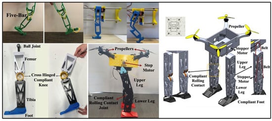
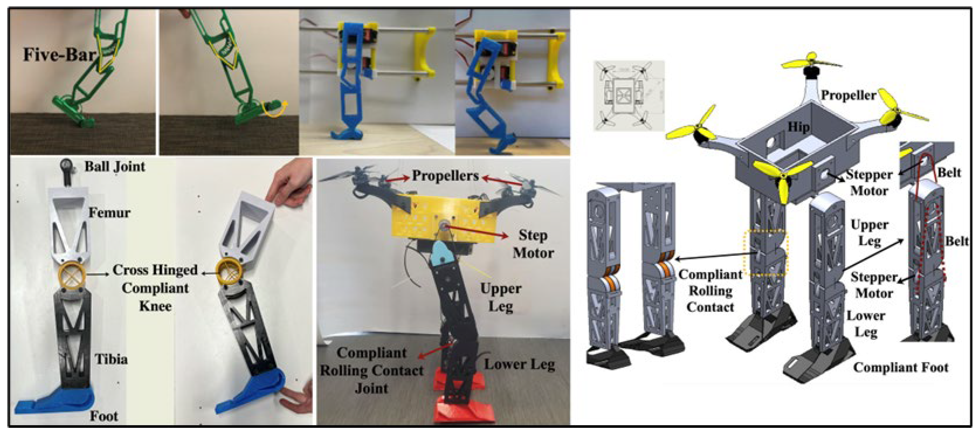
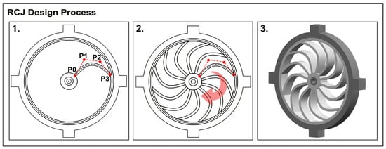
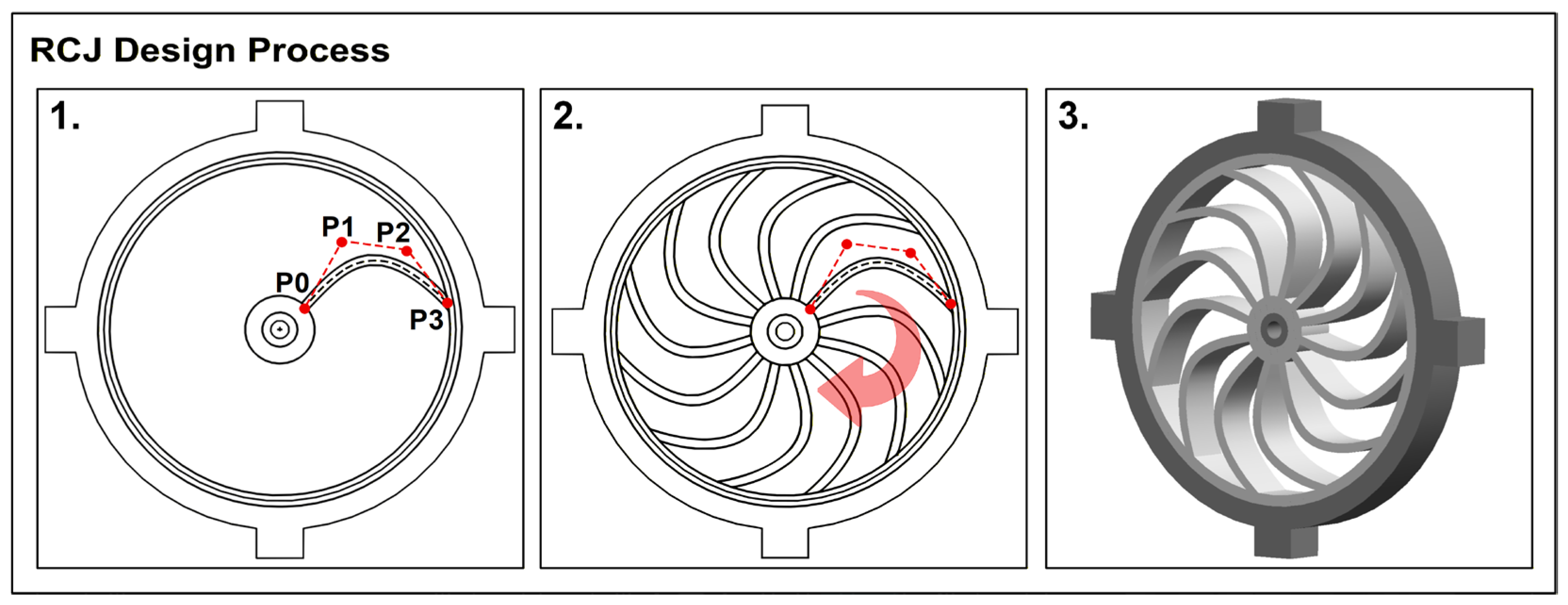
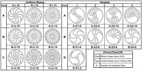
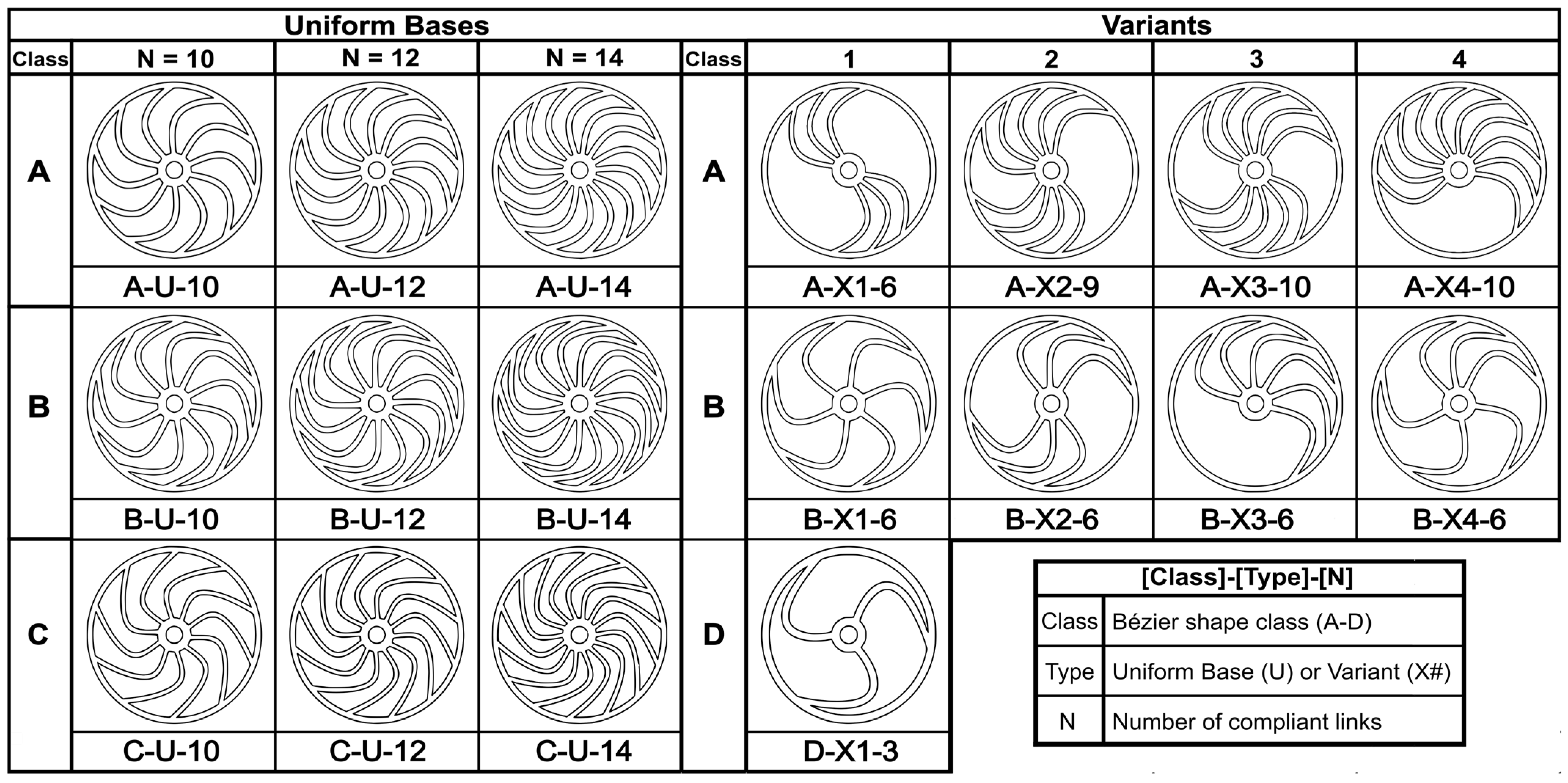
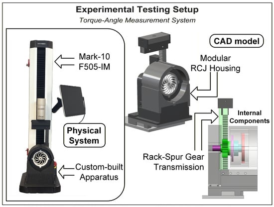
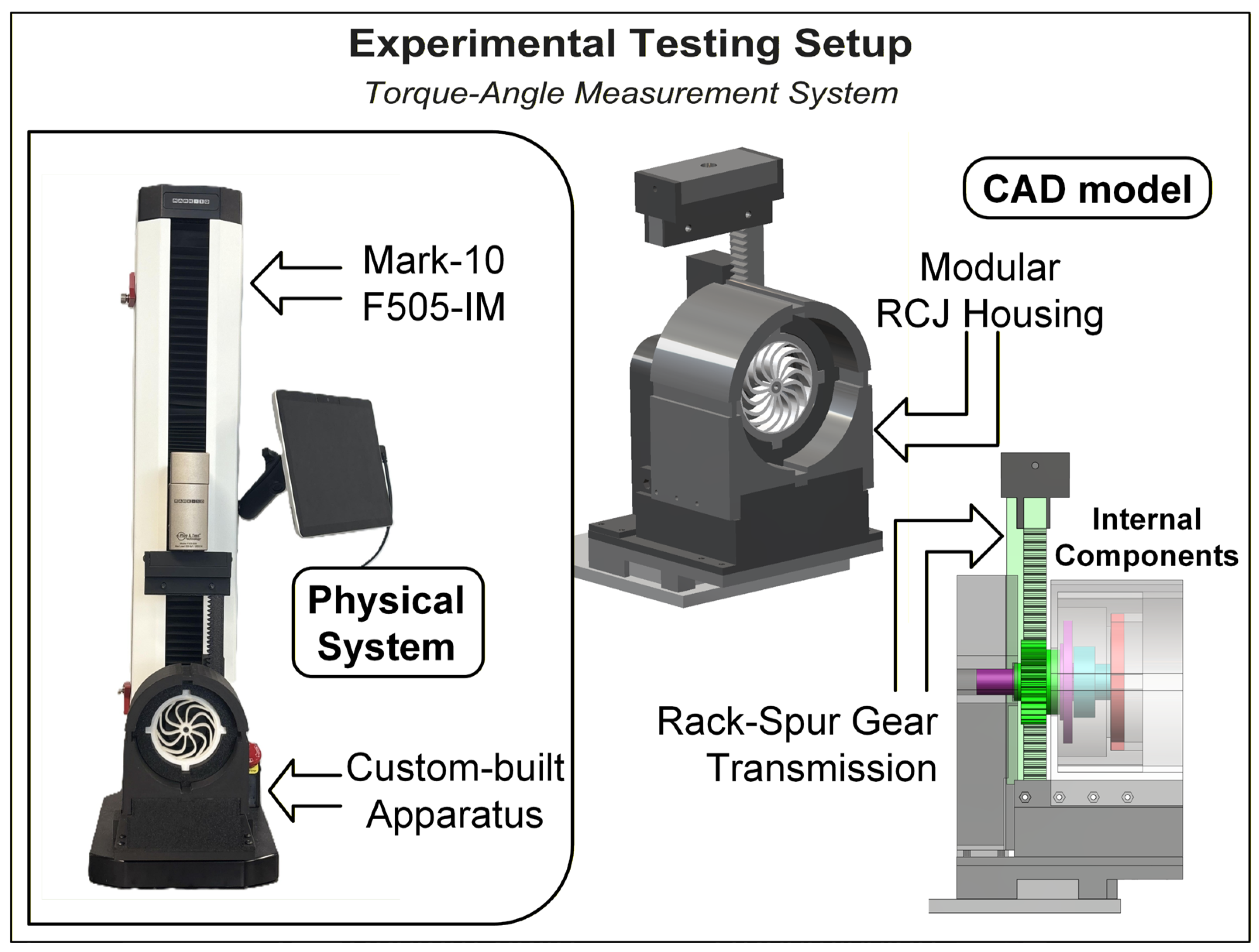
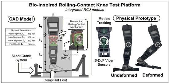
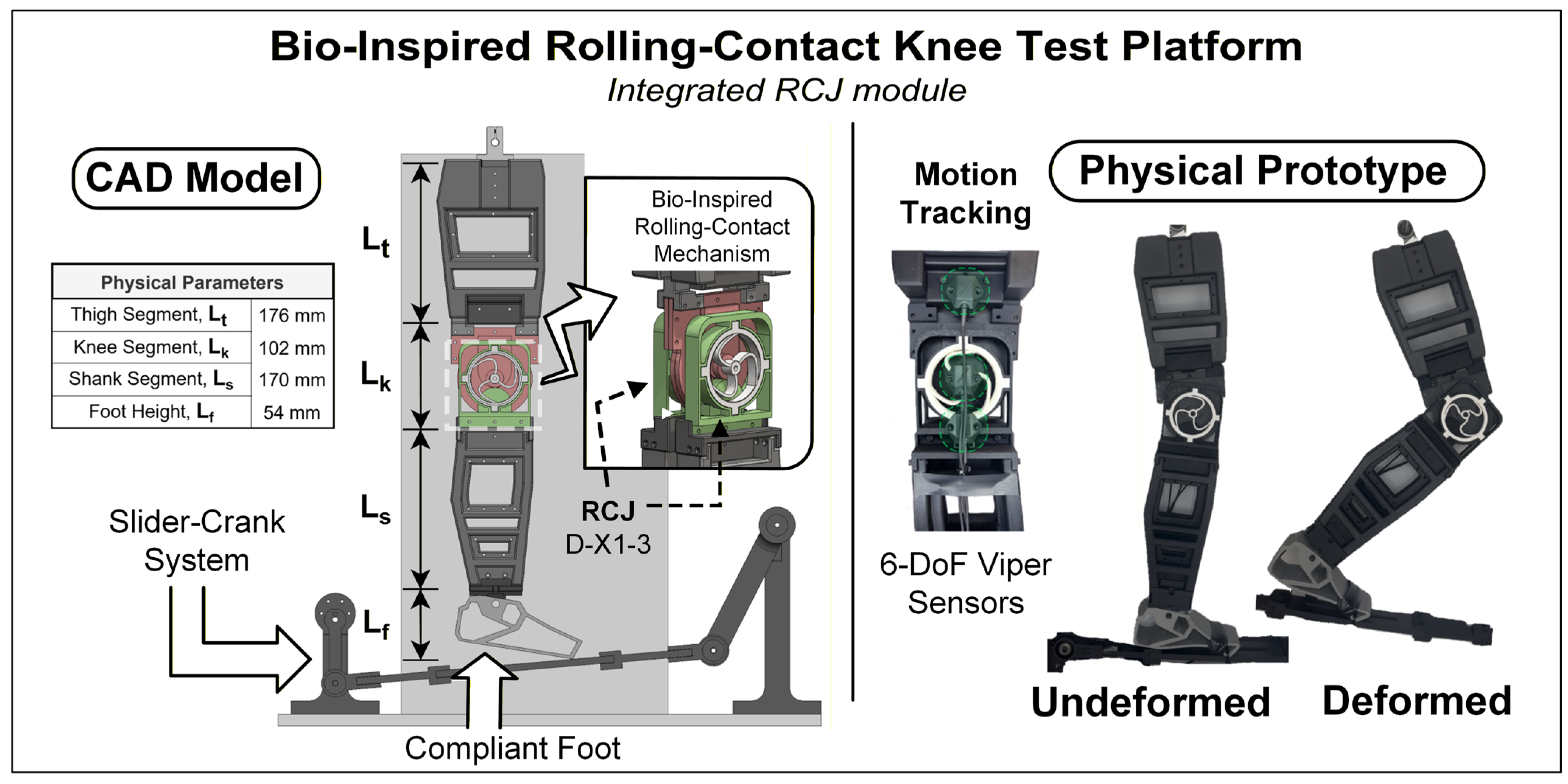


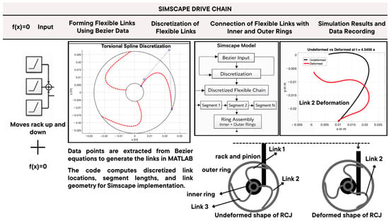
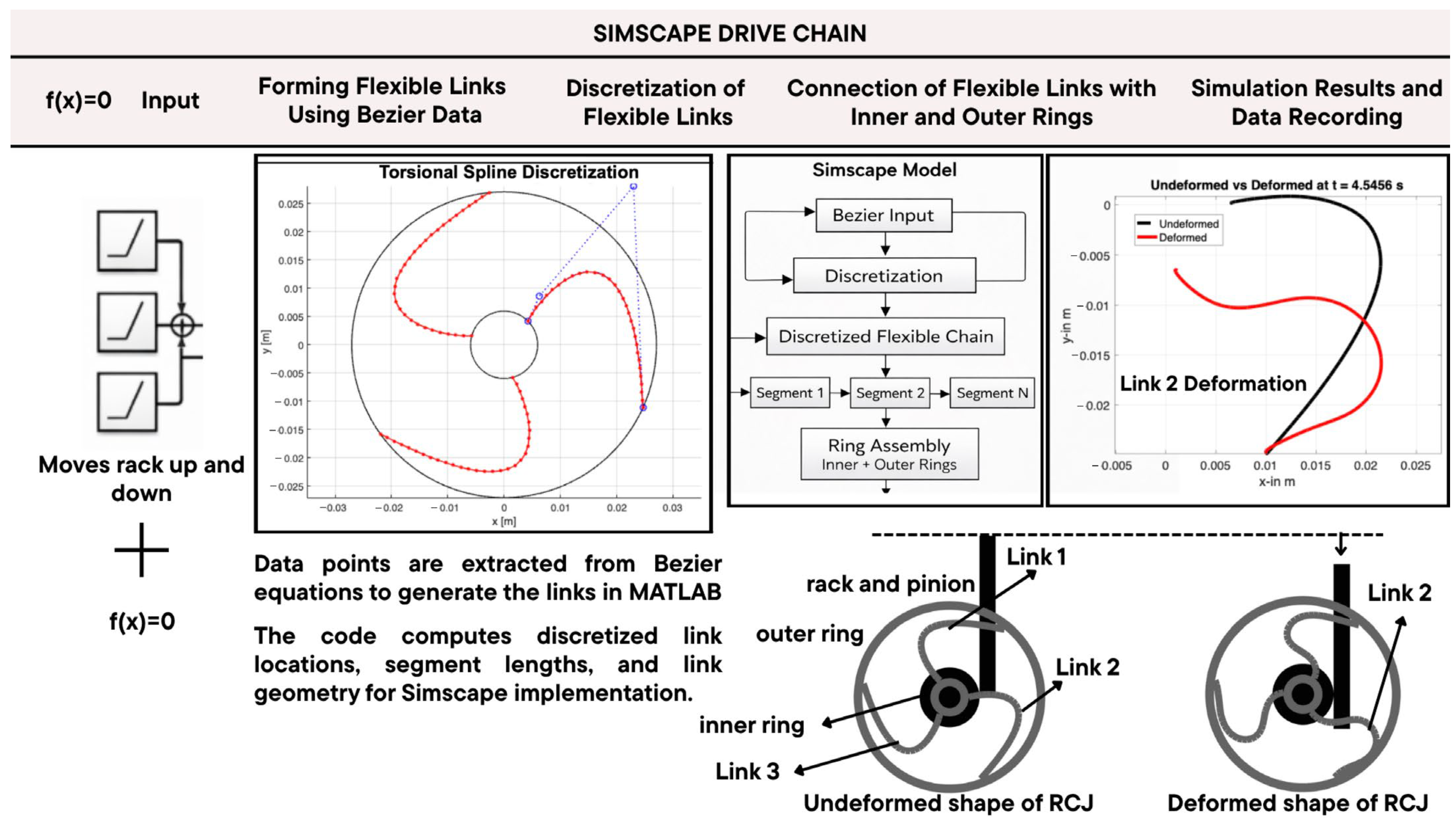
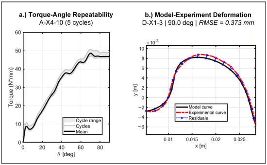
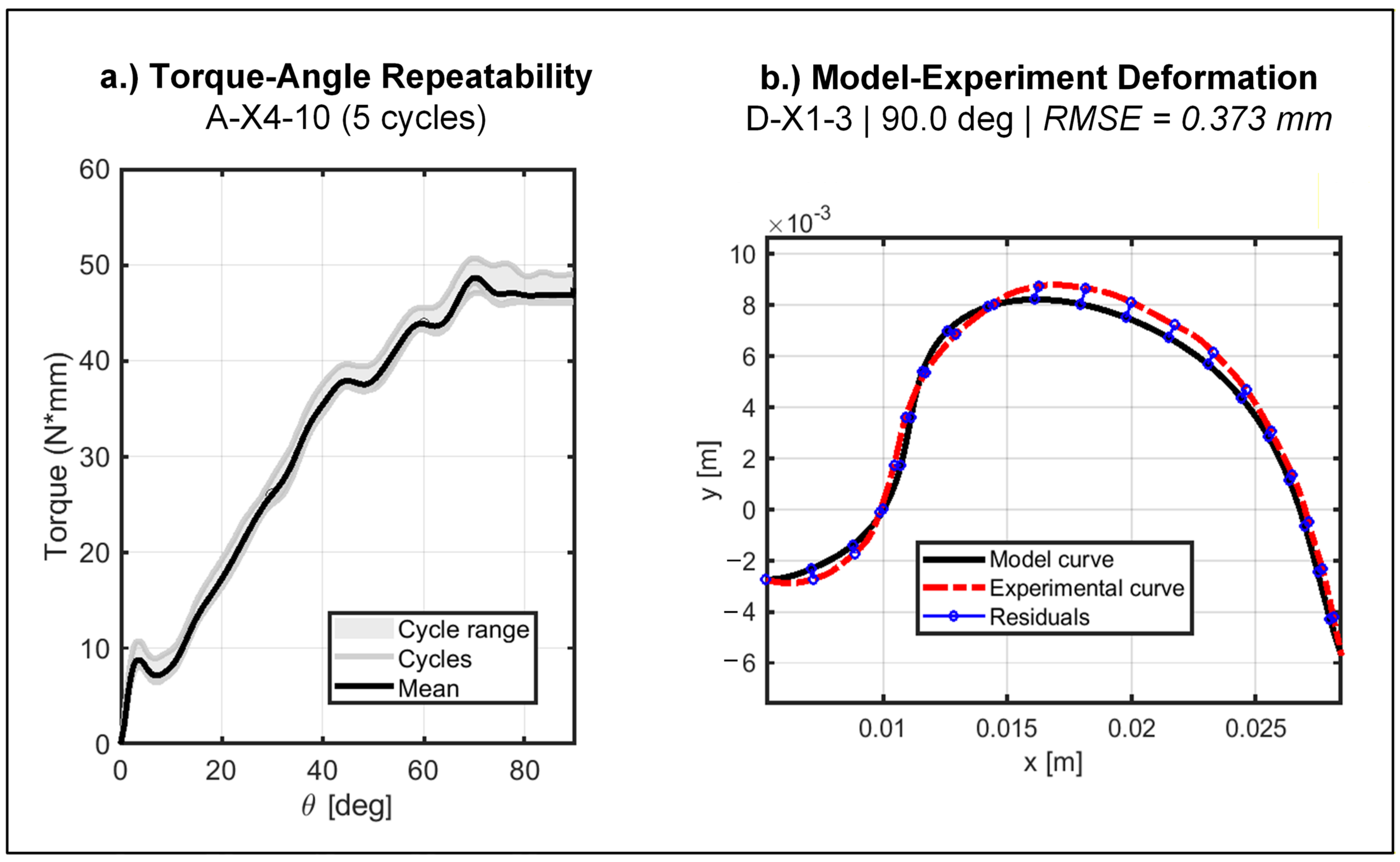
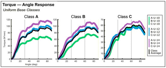
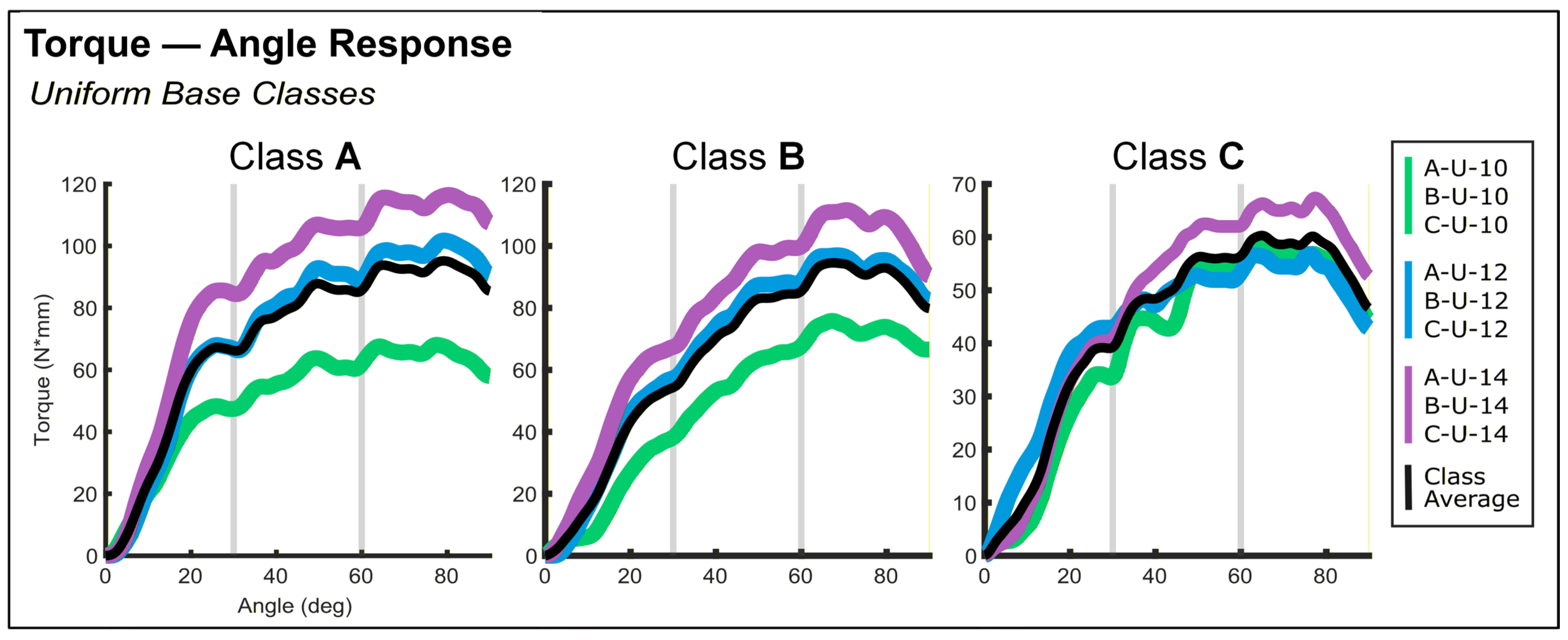
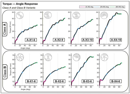
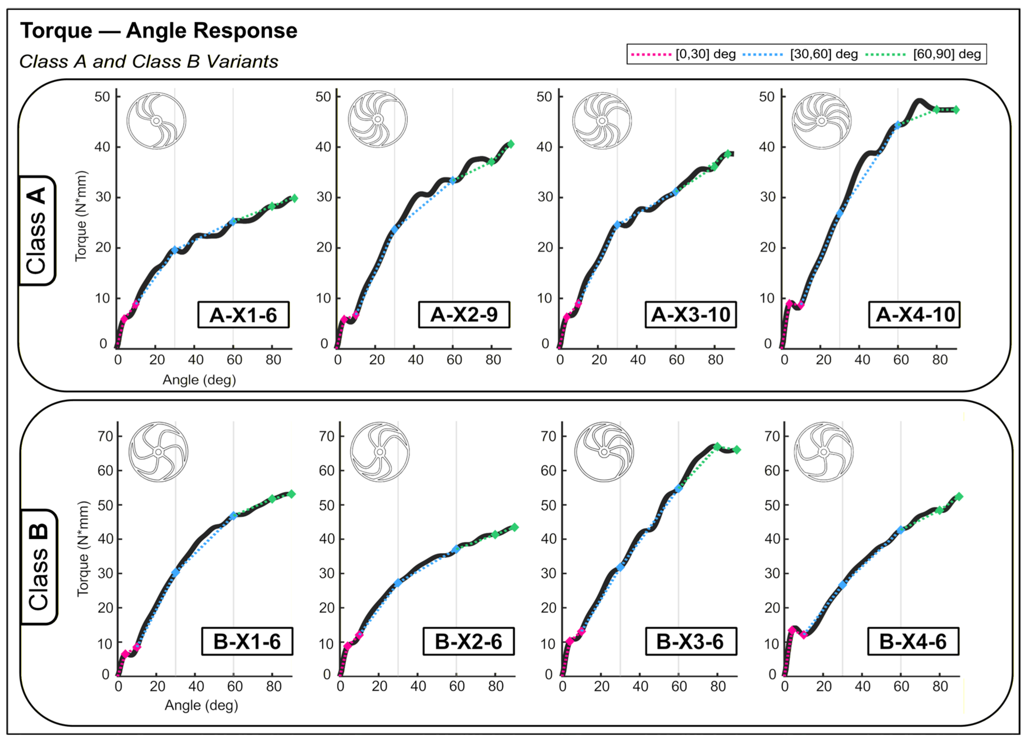
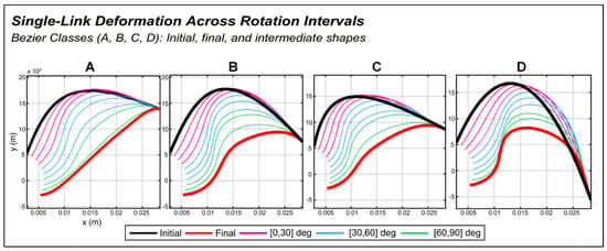
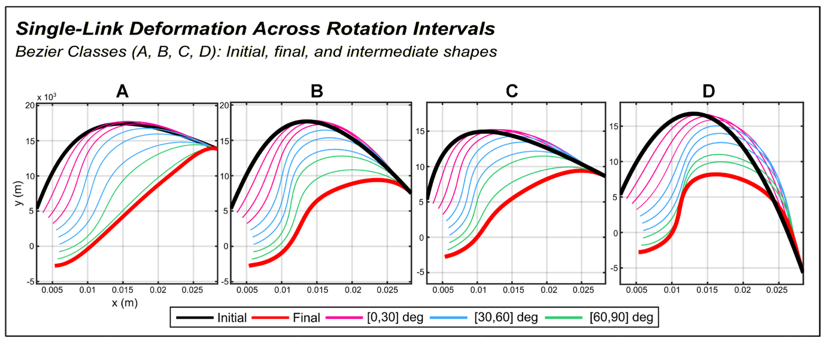
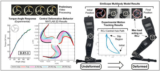
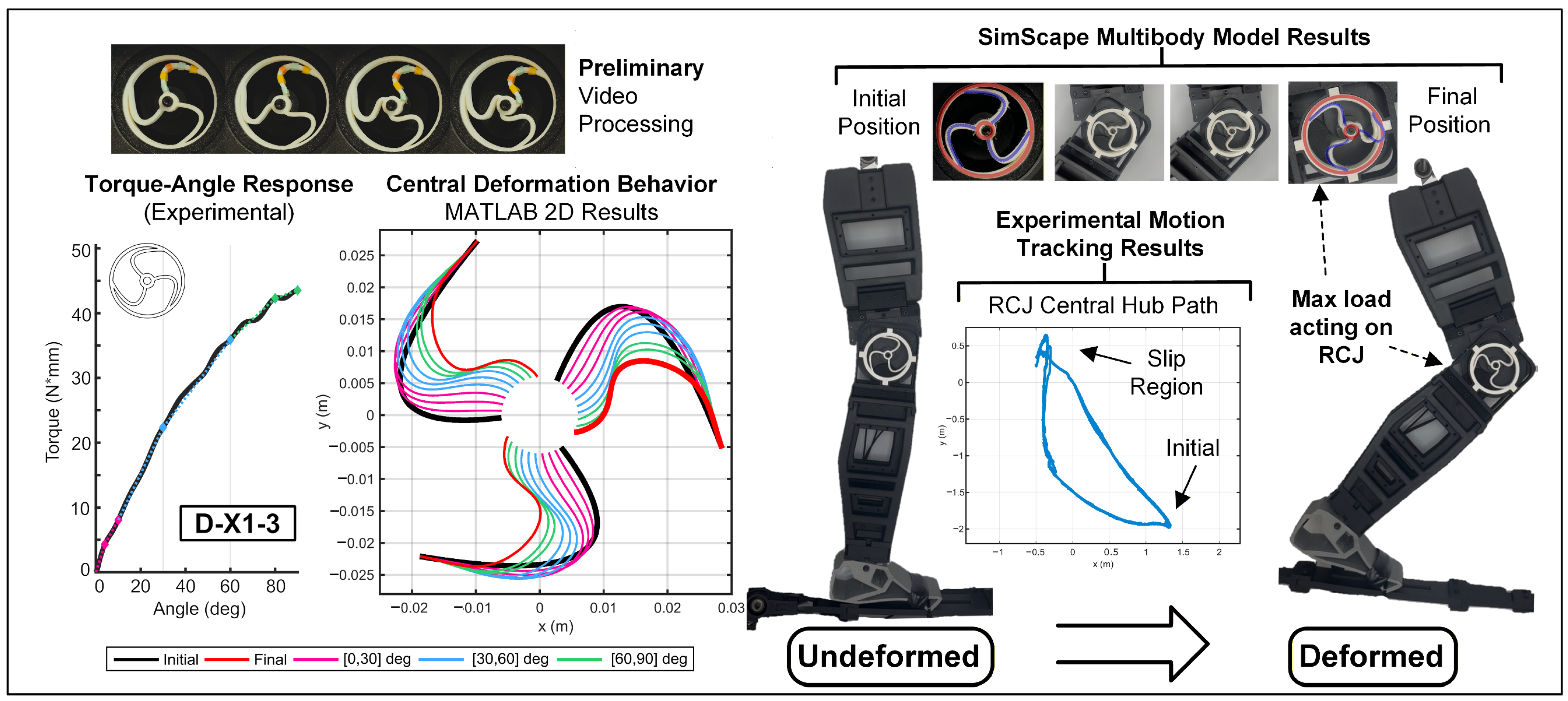

Disclaimer/Publisher’s Note: The statements, opinions and data contained in all publications are solely those of the individual author(s) and contributor(s) and not of MDPI and/or the editor(s). MDPI and/or the editor(s) disclaim responsibility for any injury to people or property resulting from any ideas, methods, instructions or products referred to in the content. |
© 2026 by the authors. Licensee MDPI, Basel, Switzerland. This article is an open access article distributed under the terms and conditions of the Creative Commons Attribution (CC BY) license.