


Abstract
The Fused Deposition Modeling (FDM) process often produces parts with high surface roughness, limiting their end-use applications, especially in the biomedical field. This paper presents an experimental study on improving the surface finish of 3D-printed polycaprolactone (PCL) samples using a robotic burnishing process. A key innovation is the development of a low-cost sensorless setup using a 5-DOF manipulator, which controls the applied force by correlating a precise robotic displacement with the known stiffness of springs via Hooke’s law. Ten PCL samples were tested using two burnishing directions: 90° (perpendicular) and 0° (parallel) relative to the printing orientation. The as-printed samples showed a highly anisotropic surface. The 90° trajectory (group 1) proved to be more effective in reducing primary roughness (), lowering the mean from to (a mean reduction of 29.9%). In contrast, the 0° trajectory (group 2) was more effective in reducing roughness , lowering its mean from to (a mean reduction of 34.0%). The results demonstrate that the proposed sensorless system is a valid method for surface post-processing of FDM parts when the required forces fall below a specific threshold, ensuring a significant reduction in roughness without damaging the samples. The lower surface roughness obtained with the proposed post-processing strategy may represent a promising approach for improving the surface characteristics of FDM-fabricated polymer scaffolds intended for biomedical applications.
1. Introduction
Additive manufacturing (AM), particularly Fused Deposition Modeling (FDM), has revolutionized prototyping and production across numerous sectors due to its versatility and low cost [1,2,3,4,5]. However, components fabricated using FDM typically exhibit inferior surface quality compared to traditional manufacturing methods. The surface of 3D printed parts is characterized by high roughness and significant anisotropy, resulting from the layer-by-layer deposition process (the so-called “stair-step effect”) [6]. This poor surface finish limits the application of FDM parts in fields that require high precision, smooth surfaces, or specific tribological properties [7]. In the biomedical sector, FDM is increasingly used for the fabrication of tissue engineering scaffolds, custom medical devices [8], and implants, utilizing biocompatible and bioresorbable polymers [9,10,11]. Among these, polycaprolactone (PCL) is a material of great interest owing to its excellent biocompatibility and longer degradation time in physiological conditions than other conventional thermoplastic polymers [12,13,14]. PCL is widely used for cartilage and bone applications thanks to mechanical and physical considerations [15,16]. Specifically, a Young modulus similar to that of the native trabecular bone tissues avoids the stress shielding effect that usually compromises the integrity of the scaffolds [17]. However, the intrinsic surface roughness of FDM-printed PCL can negatively influence cell adhesion, increase the risk of bacterial contamination, or compromise the mechanical integrity of the device [18]. Indeed, osteoblast attachment is strictly related to a proper surface roughness, which for this kind of bone cells has been found to be between 1 and 4 microns for titanium surfaces, allowing proliferation, differentiation, and viability [19]. Various post-processing techniques have been explored to improve the surface finish of FDM-printed parts. These include chemical methods (such as vapor smoothing), thermal treatments, and mechanical processes (such as CNC machining or abrasion) [20]. Among mechanical methods, burnishing, as well as similar processes such as ironing, have shown significant promise. Burnishing is a surface plastic deformation process in which a hard, smooth tool (often a sphere) is pressed and moved against the workpiece surface. This process flattens the peaks and valleys of the surface microstructure, significantly reducing roughness without removing the material. While robotic burnishing has been extensively investigated for metallic components, its application to polymeric materials is increasingly gaining attention. Recent literature has explored the burnishing of high-performance thermoplastics, such as Polyetherimide (PEI) and Acrylonitrile Butadiene Styrene (ABS), demonstrating significant improvements in surface finish and structural integrity [21,22,23]. However, unlike these relatively rigid thermoplastics, polycaprolactone (PCL) is characterized by a significantly lower yield strength, higher ductility, and pronounced viscoelastic behavior at room temperature. These distinctive material properties present unique challenges during the mechanical interaction of the burnishing tool, necessitating tailored force control strategies that differ substantially from those applied to stiffer polymers. Therefore, investigating the burnishing process specifically for PCL is crucial to bridge the current gap in the literature.
The effectiveness of the process is highly dependent on key parameters such as the applied force, tool feed rate, and material properties, as demonstrated in studies on metallic alloys [24,25]. Although this finishing process has also been used for polymers, low forces are required to achieve positive results due to a notably smaller material strength as compared to the metals [26].
In this sense, excessive contact forces applied to PCL dramatically increase the risk of severe surface degradation, localized melting, or deep material plowing. Consequently, determining an optimal, carefully calibrated force is mandatory to induce beneficial surface smearing without compromising the structural integrity of the fabricated part. This requirement is not easy to assess with robotic manipulators, even if they can be equipped with expensive sensors reflecting instability issues for very-low required forces, as in the case of polycaprolactone. Excessive force can irreversibly damage the sample. Traditional force control systems often rely on load cells or torque sensors, which significantly increase the cost and complexity of the experimental setup. To overcome this, other researchers have explored model-based sensorless approaches, often estimating external forces by observing motor currents or joint torques [27]. This study aims to address this gap by proposing an innovative, low-cost approach to robotic burnishing of FDM-printed PCL samples. After a thermal characterization of the material used in the study, it has been possible to optimize the additive manufacturing process and define the mechanical properties of the PCL, leading the way for a rational choice of parameters for the finishing process. The primary objective of this work is to develop and validate a sensorless experimental setup (i.e., lacking direct force sensors) capable of estimating and controlling the vertical burnishing force specifically for low values. This system utilizes Hooke’s law, correlating a known vertical deflection imposed by the robot with the calibrated elastic constant of the springs in a dedicated setup, thereby bypassing the need for load cells. This paper presents an experimental study to quantify the effectiveness of this system. Using a 5-DOF anthropomorphic manipulator (igus RL-DP-5) and a custom-designed rotary burnishing tool, ten PCL samples were processed with a force of 12 N. The effect of the burnishing direction (0° and 90° relative to the printing direction) on the reduction of surface roughness () was investigated, measuring the roughness before and after processing, showing promising results. Post-process values are closer to the optimal range of the required micro-roughness compared to the initial values, confirming a potential enhancement of the cell activities [28,29]. Furthermore, if the surface is intrinsically hydrophobic, as happens for polymers such as PCL, decreasing the roughness reduces the hydrophobicity, avoiding the trapping of air inside the valleys of the surface according to the Cassie-Baxter [30,31] model and leading to the creation of better scaffolds for applications that need to interact with the biological environment of tissues.
2. Materials and Methods
This section details the experimental characterization of the material properties, the custom-developed setup for robotic burnishing, and the measurement procedures used to perform the tests. To move the robot, a custom control system consisting of stepper drivers, development boards, and power supplies was designed and built. This bespoke solution was necessary to have complete control of every aspect of the movement, without using proprietary controllers and allowing for the implementation of specific, research-oriented motion profiles. In addition to hardware, custom software for the control system was developed. This software is responsible for interpreting high-level commands and generating the precise pulse sequences required by the stepper drivers, enabling the robot to follow the input trajectories defined for the burnishing process.
2.1. Material Characterization
The specimens were fabricated using a commercial polycaprolactone (PCL) filament supplied by Duomal Technology Company, Ltd. (Guangzhou, China). A preliminary thermal characterization (DSC) of the raw filament was conducted, as reported in Section Thermal Characterization, to establish its baseline thermal properties prior to the experimental printing and robotic burnishing processes.
Thermal Characterization
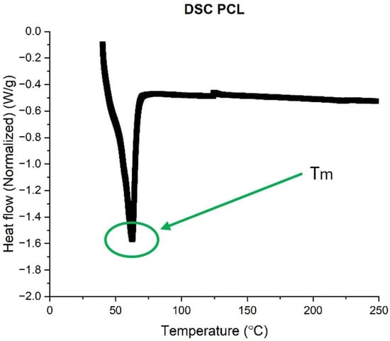
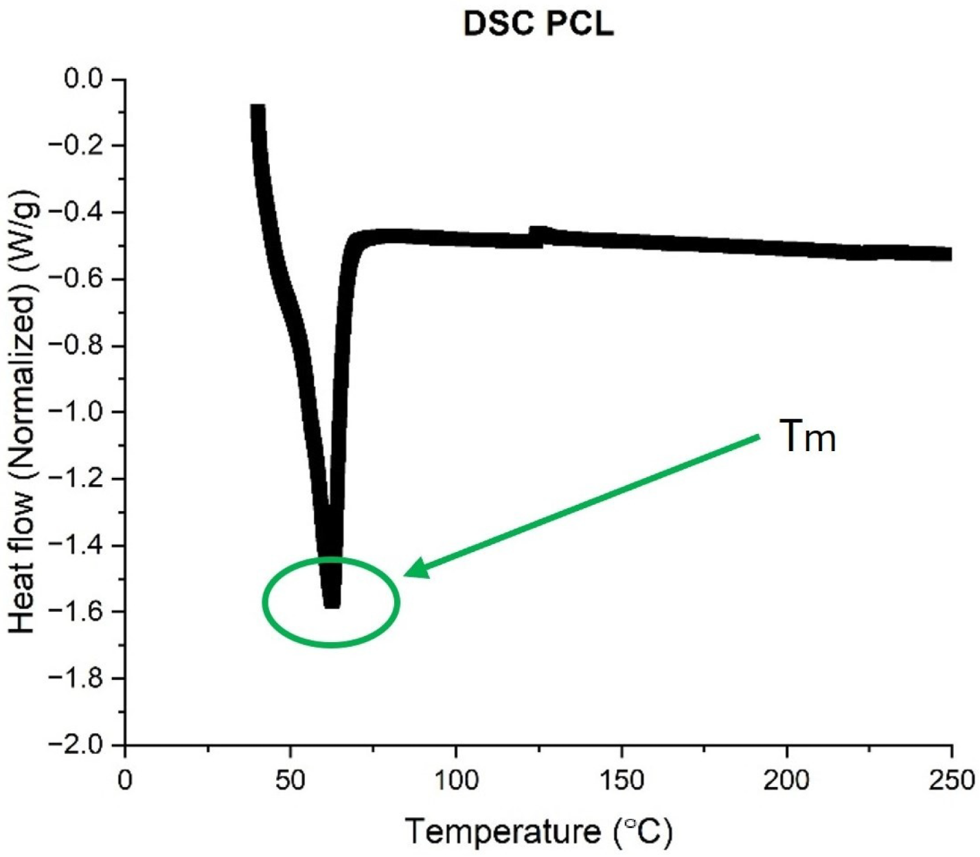
A differential scanning calorimetry (DSC) was performed with the DSC25 (TA Instruments, New Castle, DE, USA) to define the melting temperature of the material. A thermal ramp was executed with the parameters reported in Table 1 on samples placed inside an aluminum Tzero PAN and covered with an aluminum Tzero LID (Salt Lake City. UH, USA).
Table 1.
Parameter used with the differential scanning calorimetry test.
M is the mass of the samples used, n is the slope of the ramp, Ti and Tf are, respectively, the initial and final temperatures of the test. The graph reported in Figure 1 shows the melting temperature (62.5 °C) of the PCL.
Figure 1.
Differential scanning calorimetry test of PCL.
2.2. FDM Process
The study samples were printed with a square cross-section, having a side length of 30 mm. The thickness of the sample was 4 mm.
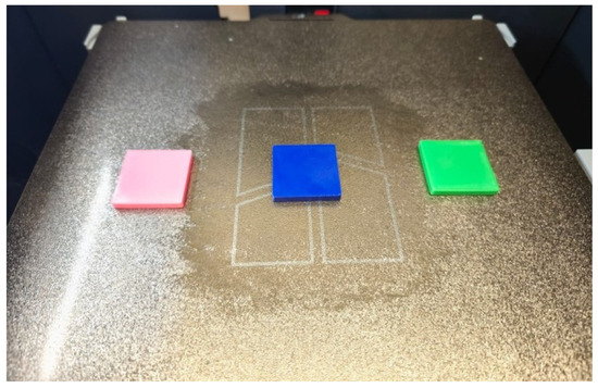
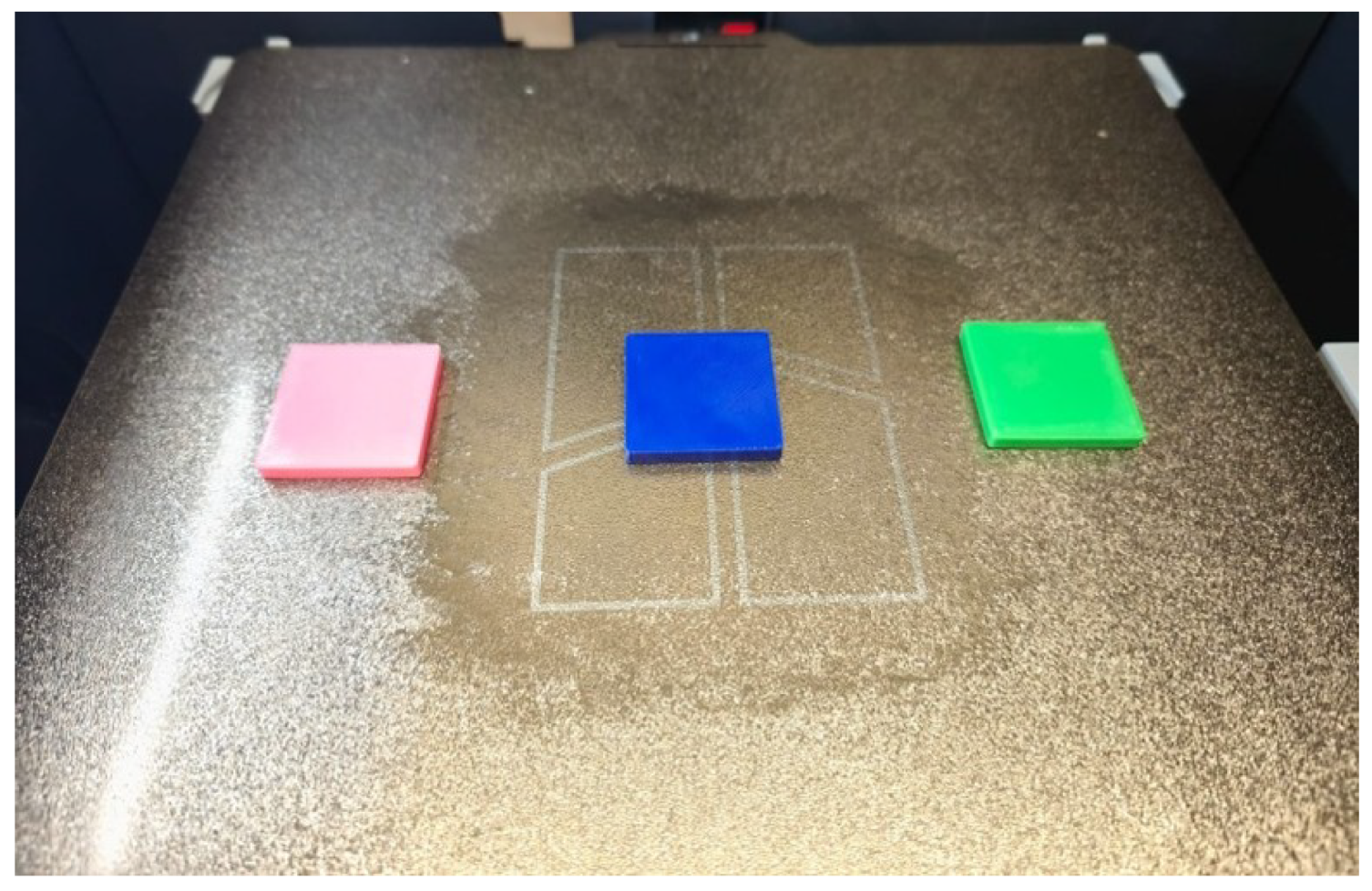
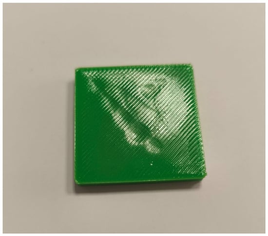
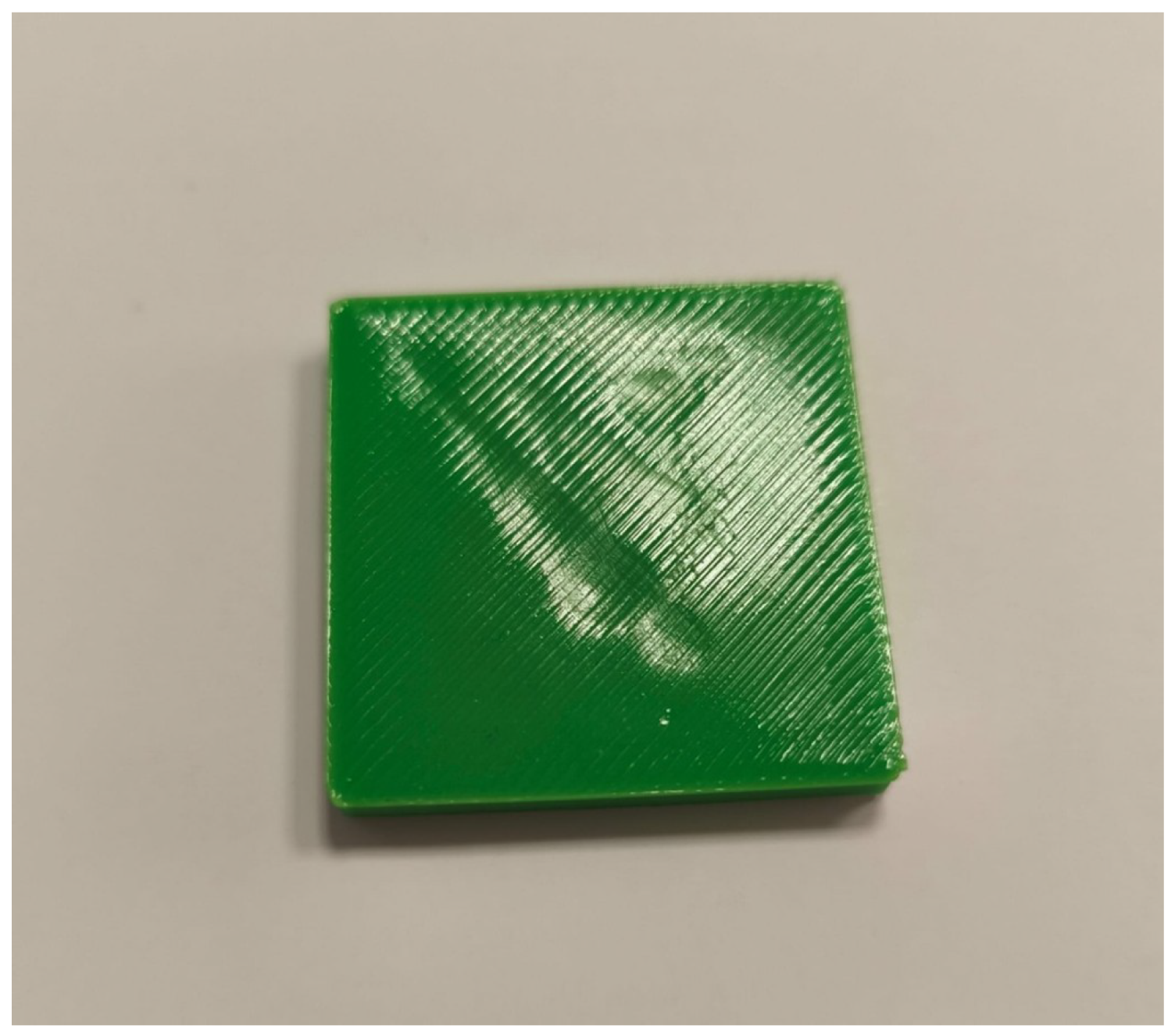
A Bambu Lab P1S (Shenzhen, China) equipped with a 0.4 nozzle and a textured PEI plate was used to print the samples in 3D with the printing parameters reported in Table 2, where t is the height of the sample layer, P is the pattern used to realize the shape, v is the printhead printing speed, the nozzle temperature and is the temperature of the printing bed. was fixed based on the data obtained in Section Thermal Characterization. Specifically, was progressively increased, starting from the identified melting temperature, until an optimal printing phase was achieved. Although the preliminary DSC analysis indicated a melting temperature of approximately 62.5 °C for the PCL filament, the FDM printing temperature was intentionally set to 120 °C. This elevated thermal profile is mandatory in FDM to adequately lower the polymer’s melt viscosity for consistent nozzle extrusion and to provide sufficient thermal energy for optimal inter-layer adhesion and structural bonding. Figure 2 reports some of the printed PCL samples.
Table 2.
Process parameters used to print PCL samples.
Figure 2.
Three-dimensional PCL samples.
2.3. Experimental Platform and Control System
The test platform used in this work exploits a Robolink-DP manipulator with 5 degrees of freedom, produced by IGUS, Cologne, Germany. Its anthropomorphic configuration provides significant dexterity and the ability to achieve complex orientations within its workspace. The use of such low-cost manipulators is becoming increasingly common in experimental research, providing a viable platform to test new control strategies and applications [32,33]. The robot is composed of 5 joints, which are driven by five stepper motors with a nominal step angle of 1.8° (200 steps per revolution), enabling precise incremental positioning. In addition, the motors are equipped with incremental encoders. The details of the five joints are reported in Table 3.
Table 3.
RL-DP-5 joints technical specifications.
Unlike traditional DC motors, a stepper motor is an electromechanical device that converts electrical pulses into discrete mechanical movements, known as “steps”. The operating principle relies on the sequential excitation of the stator phases, creating a rotating magnetic field with which the rotor aligns, moving incrementally with each pulse. This capability allows for precise and repeatable angular movements, enabling excellent positional control, often without complex feedback systems (open-loop control). This characteristic, combined with high torque at low speeds and the ability to maintain position (holding torque), makes them ideal for robotic applications requiring precise and incremental movements. In this specific manipulator, each motor is also equipped with an incremental encoder for position tracking, ensuring accuracy.
Custom Control System
The development of custom controllers for stepper-driven systems is a key enabler for advanced applications [34]. As detailed in [35], to operate the robot, a custom control system consisting of stepper drivers, a microcontroller-based development board, and regulated power supplies was designed and implemented. This solution was adopted to achieve full control over the robot motion without relying on proprietary controllers, allowing the implementation of research-oriented motion strategies and displacement-controlled experiments. The control architecture generates the pulse and direction signals required by the stepper drivers, which directly determine the angular displacement of each motor. The developed control software interprets high-level motion commands and converts them into synchronized pulse sequences, ensuring coordinated motion of the five robot joints. Considering the motor step angle (1.8°) and the microstepping configuration (1/16), the theoretical angular resolution of the actuators is 0.1125° per microstep. This high resolution enables accurate control of the vertical displacement imposed during the burnishing process, ensuring consistent application of the target burnishing force across all experiments. This level of control is fundamental for the sensorless force estimation methodology presented later, which relies on precise commanded displacements rather than direct force readings [36].
2.4. Burnishing Setup and Force Estimation
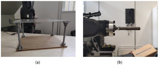
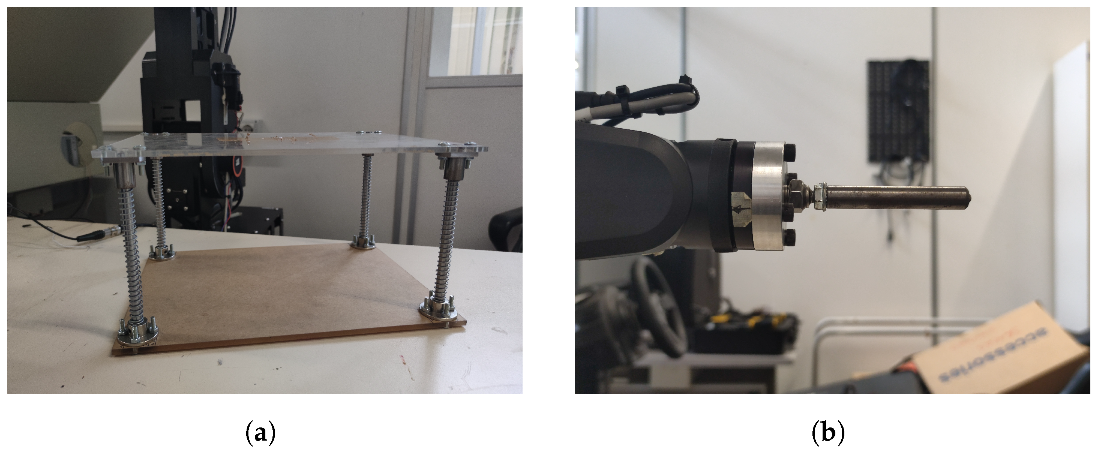
A key challenge in this research was to control the burnishing force applied without expensive and complex sensors. After designing and developing the control system for the Robolink manipulator, a burnishing setup was built to indirectly estimate and control the force applied to the sample along the Z axis, without the use of external sensors, such as load cells [37]. This setup, shown in Figure 3a, consists of two plexiglass panels: the lower panel can be fixed to the workbench (frame), while the upper panel, i.e., the plate on which the sample is fixed, is joined to the lower panel by four rods placed at the corners. Around these rods, springs with a known elastic constant (k) were installed, so as to make the plate elastically suspended.
Figure 3.
Experimental Setup: (a) sample support platform and (b) brunishing tool.
This mechanical design allows for force estimation by applying Hooke’s law:
where is the vertical force applied, k is the equivalent elastic constant of the spring assembly, and is the vertical displacement imposed by the robot after the tool is in contact with the surface of the workpiece. It is possible, by imposing a precise displacement along the Z axis controlled by stepper motors, to control the force that is applied to the material sample, without measuring it directly. During the experiment, based on the sample size, a planar X-Y trajectory was created to carry out the burnishing process. The robot maintained a fixed Z position during this trajectory to apply the desired force uniformly throughout the sample surface.
2.5. Burnishing Tool
The rotary burnishing tool (Figure 3b) was specifically designed to be securely mounted on the end effector of the robotic arm RL-DP-5. This custom design ensures a rigid connection, which is crucial for maintaining consistent force application and preventing chatter or deflection during the burnishing process. The physical length of the tool was accurately measured and integrated into the robot’s control parameters. This precise calibration is essential for the correct calculation of the inverse kinematics for all points along the burnishing trajectory. By accounting for the tool’s dimensions, the robot’s control system can accurately position and orient the tool tip relative to the workpiece surface, ensuring that the burnishing process is executed exactly as programmed. The active element of the tool, responsible for inducing plastic deformation in the sample, is a 5-mm diameter sphere made of tungsten carbide [38]. This material was chosen for its high hardness and wear resistance, which prevents tool degradation during multiple tests and ensures a consistent burnishing effect on the sample surface. The workpiece itself remains fixed on the setup plate during the operation, allowing the robot to execute complex and repeatable surface paths.
2.6. Roughness Measurement
To assess the effectiveness of the burnishing process, the roughness of the surface, , was measured before the process, providing a baseline. The measurements were then repeated after the burnishing process to assess the variation in roughness under different loads and directions. To perform the measurements, a SJ-410 surface tester, produced by Mitutoyo America Corporation, Aurora, IL, USA, was used. A rigorous protocol was followed to ensure accuracy and verify the repeatability of the results. For each sample, before and after burnishing, five distinct measurements were taken at different locations. Crucially, each measurement consisted of readings in three different directions, 0°, 45°, and 90° relative to the 3D printing direction, so that three roughness features could be extracted: perpendicular, hereafter for 90°; parallel, hereafter for 0°; and oblique, hereafter , for 45°. This way, the anisotropic nature of 3D-printed surfaces is accounted for by [39]. The final roughness value for each sample and each direction was then calculated as the average of the five measurements. This comprehensive measurement procedure was performed on the sample piece both before and after the burnishing process.
2.7. Experimental Parameters and Samples
The methodology for the experimental campaign involved a structured variation of parameters and the precise definition of the tool path used for the burnishing operation. The burnishing process was performed on ten 3D printed samples. The experimental plan was designed based on two key parameters: applied vertical force () and burnishing direction () (Table 4). The value of was imposed to be equal to 12 N. This force value was selected empirically based on a series of preliminary tests aimed at identifying the optimal balance between surface improvement and structural preservation. Given the viscoelastic properties of PCL, higher forces proved detrimental. For instance, preliminary trials conducted at 25 N resulted in excessive plastic deformation, creating an overly wide groove that severely damaged the specimen rather than improving its surface finish (as shown in Figure 4). Therefore, 12 N was identified as a safe and effective threshold to achieve the desired burnishing effect. This value was calculated based on the spring deflection in Section 2.2 and on the mechanical characteristics of the material. Concerning the parameter , two different burnishing directions were tested, defined relative to the inherent printing direction (i.e., the direction of the extruded filaments) of the test sample: 90° (perpendicular) and 0° (parallel). The ten samples were divided into two groups: the first five samples with a burnishing angle of 90° (group 1), while the last five had a burnishing angle of 0° (group 2).
Table 4.
Burnishing angles and forces applied.
Figure 4.
Burnished sample with a force of 25 N.
To ensure that the entire mm surface of each sample was processed uniformly, a specific tool path was generated using custom control software. The goal was to create a “scanning” pattern with a precise step-over to ensure full coverage. A single consistent tool path trajectory was used for all the experiments. To achieve the two different experimental conditions relative to the FDM printing direction (90° and 0°), the samples themselves were physically rotated on the fixture plate. For group 1, the samples were fixed, so their internal printing direction was oriented at −45° relative to the X axis of the setup. This alignment ensured that the 45° machine trajectory moved perpendicularly 90° across the printed filaments. The samples of group 2 were rotated and fixed, so their internal printing direction was oriented at +45° relative to the X axis of the setup. This alignment ensured that the 45° machine trajectory moved parallel (at 0°) along the printed filaments. This method ensured that the robot performed the same motion for all tests, guaranteeing repeatability, while the relative angle between the tool and the printed filaments was 90° or 0°, as intended by the experimental plan (Table 4). During the execution of this X-Y trajectory, the robot control system maintained a fixed position along the Z axis to apply the constant burnishing force of 12 N.
3. Results
3.1. As-Printed Surface Characterization
The initial surface roughness () of all 10 PCL samples was measured before burnishing. The as-printed surfaces exhibited a high degree of anisotropy, a characteristic feature of the FDM process. The roughness measured perpendicular to the printing direction () was consistently the highest, with an average value of 2.11 for group 1 and 2.35 for group 2. In contrast, the roughness measured parallel to the printing direction () was the lowest, with averages of 0.274 and 0.225 for group 1 and group 2, respectively. The initial measured at 45° () showed intermediate values (see Table 5). It is worth noting that for certain specimens, the surface improvement was relatively low. These deviations can be directly attributed to the initial surface variations inherent to the Fused Deposition Modeling (FDM) process. FDM is known to produce microscopic inconsistencies, such as uneven layer heights, localized under-extrusion, or inter-layer voids. When a localized initial defect is deeper than the plastic deformation zone induced by the burnishing tool, or when the initial topography is extremely irregular, a constant applied force of 12 N may not be sufficient to completely smear the peaks into the valleys. Consequently, the effectiveness of the burnishing process is highly sensitive to the initial micro-topography of the as-printed part, leading to the observed variations in surface roughness reduction.
Table 5.
Detailed () results and percentage reduction for all samples, grouped by treatment trajectory.
3.2. Effects of Burnishing Trajectory
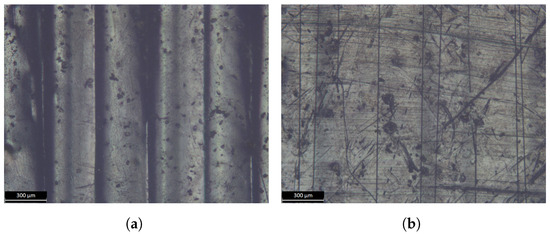
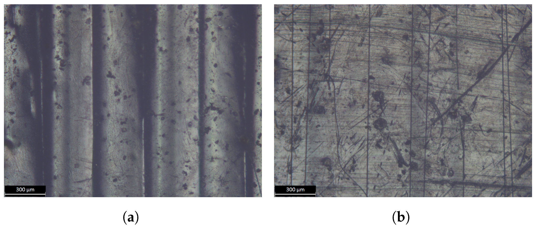
After the initial characterization, the two groups of samples were burnished using the sensorless robotic system with a force of 12 N, applying the two different trajectories described in Section 2.7. Qualitative images of the burnishing effect on the surface of one of the tested samples, acquired by the Leica Microsystems (Heerbrugg, Switzerland) Optical microscope S6 D, are displayed in Figure 5.
Figure 5.
Optical Microscope surface images: (a) before burnishing and (b) after burnishing.
In Figure 5a, the extrusion beads, owing to the FDM parameters and nozzle size, can be observed on the sample surface. The burnishing effect results in smoothening of the above-mentioned beads (Figure 5b).
3.2.1. Group 1: Perpendicular Trajectory
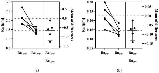
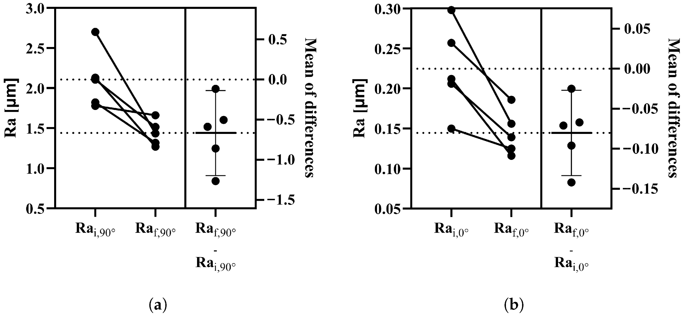
The five samples in group 1 were burnished with a tool path perpendicular to the printing direction. This treatment was most effective in reducing measured at 90°. On average, was reduced from 2.11 to 1.44 , corresponding to a mean reduction of 29.9%. This reduction was found to be statistically significant (paired t-test, p < 0.05). The treatment also positively affected the other measurement directions, achieving a mean reduction of 18.8% for and 23.0% for . The detailed results for each sample in Group 1 are presented in Table 5 and Figure 6a.
Figure 6.
Effectiveness of the burnishing trajectories (n = 5 per group), shown as paired ’before-after’ plots. (a) Effect of the perpendicular trajectory on roughness (group 1). (b) Effect of the parallel trajectory on roughness (group 2). Lines connect measurements from the same sample. In both cases, the reduction was statistically significant (paired t-test, ).
3.2.2. Group 2: Parallel Trajectory
The samples in group 2 were processed with a tool path parallel to the printing direction. In contrast, this strategy was most effective in reducing measured at 0°. The average was reduced from 0.225 to 0.144 , achieving a mean reduction of 34.0%. This reduction was also found to be statistically significant (paired t-test, p < 0.05). This treatment also reduced by an average of 22.0% and by 19.6%. The detailed results for group 2 are also reported in Table 5 and Figure 6b.
4. Discussion
The results presented in this study demonstrate two primary findings: first, that the novel low-cost sensorless force control setup is a viable and effective method for robotic burnishing; and second, that the burnishing strategy significantly and statistically reduces the anisotropic surface roughness of FDM-printed PCL parts, attesting to their values within the optimal range for osteoblast attachment. The surface smoothing achieved through robotic burnishing is primarily governed by a “smearing” mechanism, which is deeply influenced by the pronounced viscoelastic nature of PCL at room temperature. Unlike metals, where burnishing induces purely elasto-plastic deformation, polymers exhibit a time-dependent flow mechanism. As the spherical tool compresses the surface asperities, the localized stress exceeds the yield point of the FDM-printed PCL, initiating plastic flow that displaces material from the peaks into the adjacent valleys. However, due to the viscoelastic relaxation and creep behavior of the polymer, the material flow is highly sensitive to the interaction time (feed rate) and the applied force. If the force is adequate, the time-dependent plastic deformation dominates, successfully smearing the surface; if excessive, it leads to detrimental plowing and material pile-up, as observed in our preliminary tests [40,41,42].
4.1. Analysis of Burnishing Effectiveness and Anisotropy
The “as-printed” surface characterization confirmed what is widely documented in the FDM literature: the inherent anisotropic nature of the part surface. The roughness measured perpendicular to the deposited layers was, as expected, the main contributor to the overall roughness, with average values exceeding 2.1 µm due to the pronounced “stair-step effect”. In contrast, the roughness parallel to the filament was nearly one order of magnitude lower. The analysis of the two experimental groups revealed a logical and significant correlation between the direction of the tool path and the direction of maximum roughness reduction.
- Group 1 (Perpendicular Trajectory): This group demonstrated the most substantial reduction (29.9%, p < 0.05) in the measurement. This result is physically sound; a tool path perpendicular to the layers applies the 12 N force optimally to plastically deform and “flatten” the layer peaks. The tungsten carbide sphere effectively “smears” the filament crests into the adjacent valleys, directly addressing the main cause of the stair-step effect. This aligns with the findings of other mechanical post-processing studies in which the orientation of the tool path is critical to mitigating the directional surface properties of FDM [43,44].
- Group 2 (Parallel Trajectory): In contrast, this strategy was the most effective in reducing roughness (34.0%, p < 0.05). This suggests that a parallel “ironing” motion is ideal for smoothing micro-irregularities along the filament bead itself (e.g., die swell or vibration ripples from the extruder). Although it also reduced (by 22.0%), it was logically less effective than the direct approach for that specific task.
These findings not only validate the process but also suggest that robotic burnishing can be employed to selectively engineer the final surface anisotropy. Depending on the final application (e.g., fluid dynamics versus tribology), a 90° path could be chosen for maximum general smoothness, or a 0° path could be used to optimize surface properties along a specific functional direction. However, it must be noted that the smoothing capability of a constant-force burnishing approach is inherently limited by the initial surface variations typical of the FDM process. Localized defects such as under-extrusion, uneven layer adhesion, and micro-voids create topological anomalies that can occasionally exceed the plastic deformation range of the tool. Consequently, these FDM-induced structural inconsistencies account for the relatively lower surface improvements observed in specific localized areas, highlighting that the ultimate effectiveness of the robotic burnishing process remains partially dependent on the baseline print quality.
4.2. Validation of the Sensorless Force Control Approach
A primary contribution of this work is the validation of the experimental setup itself. Although robotic force control is often dominated by expensive 6-axis F/T sensors or complex sensorless model-based approaches (e.g., motor current observers), this study demonstrates a robust alternative. Our method utilizes passive mechanical compliance (the spring assembly) for active force control.
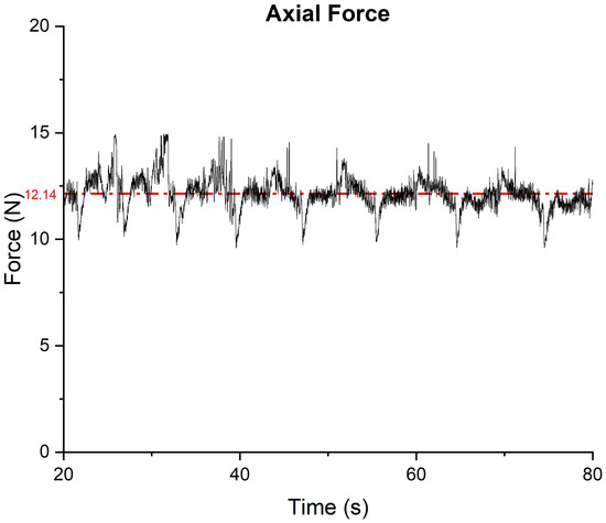
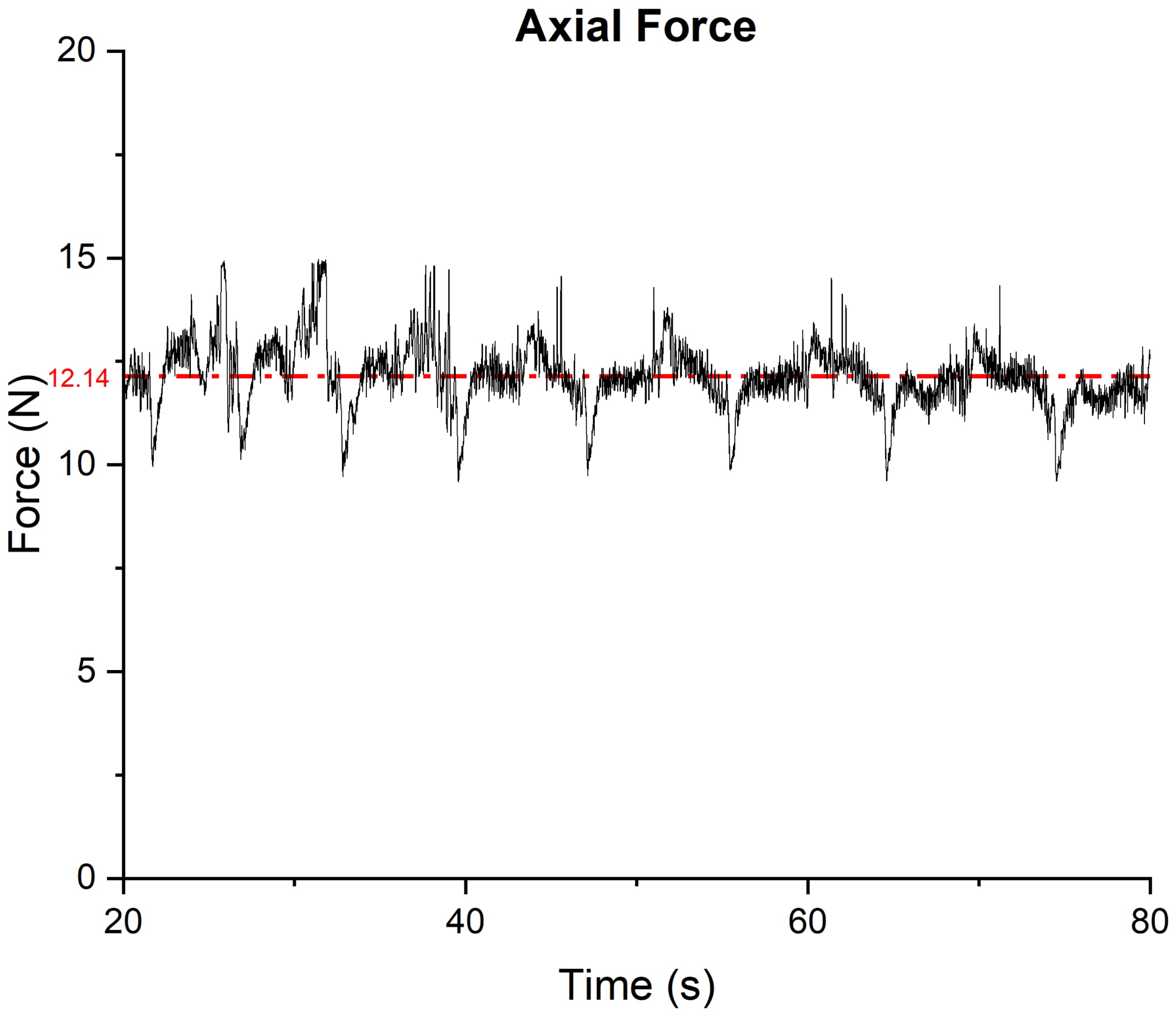
By precisely controlling the robot Z-axis displacement (), we reliably apply a precalculated force () without any force feedback loop. This hybrid passive-active approach is distinct from traditional passive compliance, which only reacts to the environment, and sensorless methods based on models that estimate, rather than set, the force [45]. For validation purposes, the robotic arm was equipped with a Robotiq FT300S—6-axis Force and Torque sensor (Robotiq, Yamanashi, Japan) to measure the contact force between the tool and the sample during the burnishing processes. An outcome of such measurements is shown in Figure 7, which demonstrates how the proposed setup allows for the accurate control of the contact force, with an average value of the measured force equal to 12.14 N and a standard deviation equal to 0.78 N. The statistically significant and consistent reductions in roughness (as shown in Figure 6) confirm that the target force of 12 N was applied effectively and repeatedly across all samples, validating the entire custom-built robotic system. Although other studies achieved higher roughness reductions in different polymers (e.g., 70% on PEI [46]), our result of 30% on PCL was achieved with a significantly less complex and more cost-effective system, proving its viability.
Figure 7.
Measure contact force in the axial direction between tool and sample during the burnishing process.
4.3. Limitations and Future Work
Although this study provides clear results, its scope is intentionally focused. Primary limitations include the use of a single material (PCL) and a single force level (12 N). Future work should expand on this successful validation with a broader factorial experimental plan.
- Force and Speed Variation: Investigating the interaction between different force and tool feed rates to find the optimal parameters for PCL.
- Material Comparison: This methodology can be applied to other common biomedical polymers (e.g., PLA, PLGA, and PEEK) to build a comparative database.
- Complex Geometries: Using the 5-DOF manipulator to apply the burnishing tool to curved and complex surfaces, which is a key advantage of robotics over 3-axis CNC machining and is critical for biomedical applications like custom implants.
While a more comprehensive topographical assessment, including parameters such as and , would provide a deeper understanding of the surface texture, this initial study primarily focused on the parameter as the foundational indicator of surface finish improvement. From a biomedical perspective, is widely recognized as a critical factor influencing cell-material interactions. As previously reported in the literature [19], surface average roughness values in the order of magnitude obtained in this study have been shown to promote optimal osteoblast attachment and proliferation. Although such studies often refer to metallic implants rather than polymeric substrates, the resulting micro-topographical scale required for cellular integration is highly comparable. This suggests that the reduction achieved through the robotic burnishing of PCL holds significant potential for future tissue engineering applications. Future investigations will naturally incorporate advanced 3D surface mapping and morphological analyses to further characterize the functionalized scaffolds. However, although polycaprolactone (PCL) is highly regarded for its biocompatibility, it is important to clarify that the present study focuses exclusively on the mechanical and topographical enhancement of 3D-printed surfaces. This research does not include experimental biological validations such as cell culture tests, wettability measurements (contact angle), SEM morphology analysis, or in-vitro biocompatibility evaluations. Consequently, the suitability of the proposed robotic burnishing method for the direct fabrication of biomedical scaffolds remains a literature-based projection at this stage. Future investigations will naturally incorporate advanced 3D surface mapping and morphological analyses, alongside comprehensive biological assays, to fully assess the functional suitability of the burnished PCL surfaces for specific clinical applications. In parallel, to further optimize the robotic process, a more comprehensive design of experiments will be conducted to explore varying burnishing forces, feed rates, and tool dimensions. In this broader context, advanced statistical techniques, such as Analysis of Variance (ANOVA), will be employed to thoroughly evaluate the main effects and potential interactions of multiple process parameters on the final surface topography.
5. Conclusions
This paper presented the development and successful validation of a low-cost, sensorless robotic system for the post-processing of FDM-printed PCL components. The primary objective was to control the burnishing force without relying on expensive force/torque sensors, instead correlating a precise robotic displacement with the mechanical compliance of a custom spring-based setup via Hooke’s law. The experimental results demonstrated that this approach is both viable and effective. The application of a calculated 12 N force significantly reduced the surface of all PCL samples, and the reductions were found to be statistically significant (paired t-test, p < 0.05). These results confirmed promising values for bone tissue regeneration, considering the values achieved in the optimal range of this biomedical area. Furthermore, the reduction in roughness (below 2 ) could potentially induce it to partially abandon the Cassie-Baxter regime, improving the perceived hydrophilicity and reducing the contact angle, thus promoting wettability and confirming the suitability for native biological tissues. The study also confirmed the importance of the tool path strategy in relation to the FDM’s inherent anisotropy:
- A perpendicular trajectory was most effective in reducing the primary roughness, with a mean reduction of 29.9%.
- A parallel trajectory was most effective in reducing roughness, with a mean reduction of 34.0%.
From an industrial and operational perspective, the proposed spring-based indirect measurement approach presents concrete advantages over traditional CNC-based burnishing systems. Conventional setups typically require expensive multi-axis force/torque sensors and complex, high-frequency closed-loop control architectures to maintain a constant tool pressure. In contrast, our passive force estimation method significantly reduces overall hardware costs and system complexity by leveraging a simplified control strategy based on Hooke’s law and precise robotic displacement. However, it must be acknowledged that the current study is limited to the burnishing of flat PCL surfaces. The application of this sensorless approach to complex, free-form 3D geometries remains a challenge. Future work will focus on further validating the process on curved parts, which will require the development of advanced spatial kinematic compensation algorithms to maintain consistent tool-surface interaction across varying topologies.
In conclusion, this work validates a novel sensorless system as a cost-effective and reliable method to improve the surface finish of FDM parts when the required forces are very low due to the softer nature of the biocompatible polymers. It provides a robust alternative to complex force control systems and confirms that robotic burnishing can be strategically employed to selectively target and reduce surface anisotropy of polymeric biomedical scaffolds. Furthermore, with this kind of prototype, it is also possible to investigate lower levels of force by understanding the influence of this parameter on the final results and related cell attachment varying, at the same time, polymers with notable biocompatibility that often consist of low mechanical properties and therefore require a high degree of accuracy during manufacturing processes.
Author Contributions
G.S.: Conceptualisation, methodology, software, validation, formal analysis, investigation, Robot Control, data acquisition, original draft writing, visualization. C.B.: Investigation (Material Characterization—DSC—Manufacturing process), Visualization, Review Writing and Editing. M.P.: Methodology, Robot Control, data acquisition, and review. L.D.N.: Resources and review. F.G.: Administration and review of the project. D.M.: Conceptualization, supervision, acquisition of funding, resources, writing, and review. All authors have read and agreed to the published version of the manuscript.
Funding
This research work has been carried out in the context of the project “Centro Nazionale di Ricerca in High-Performance Computing, Big Data and Quantum Computing”, Project Number CN00000013, CUP H23C22000360005 and of the National Recovery and Resilience Plan, Investment PE8—Project Age-It: “Ageing Well in an Ageing Society” cofunded by the Next Generation EU [DM 1557 11.10.2022]. The views and opinions expressed are only those of the authors and do not necessarily reflect those of the European Union or the European Commission. Neither the European Union nor the European Commission can be held responsible for these issues.
Data Availability Statement
The raw data supporting the conclusions of this article will be made available by the authors upon request.
Conflicts of Interest
The authors declare no conflicts of interest.
References
- Testoni, O.; Bodkhe, S.; Bergamini, A.; Ermanni, P. Network of selectively compliant actuators based on shape memory alloys and polymers for a reconfigurable sandwich panel. J. Intell. Mater. Syst. Struct. 2022, 34, 341–351. [Google Scholar] [CrossRef] [Scilit]
- Bishay, P.L.; Finden, R.; Recinos, S.; Alas, C.; Lopez, E.; Aslanpour, D.; Flores, D.; Gonzalez, E. Development of an SMA-based camber morphing UAV tail core design. Smart Mater. Struct. 2019, 28, 075024. [Google Scholar] [CrossRef] [Scilit]
- Dipu, M.N.H. An overview of additive manufacturing technology: Generic steps, fundamental categories, advantages, disadvantages, and applications. Next Res. 2025, 2, 100909. [Google Scholar] [CrossRef] [Scilit]
- Arif, Z.U.; Khalid, M.Y.; Noroozi, R.; Hossain, M.; Shi, H.T.H.; Tariq, A.; Ramakrishna, S.; Umer, R. Additive manufacturing of sustainable biomaterials for biomedical applications. Asian J. Pharm. Sci. 2023, 18, 100812. [Google Scholar] [CrossRef] [Scilit]
- Ou, Y.; Köllner, A.; Dönitz, A.G.; Richter, T.E.; Völlmecke, C. Material extrusion additive manufacturing of novel lightweight collinear stayed polymer lattices. Int. J. Mech. Mater. Des. 2024, 20, 991–1007. [Google Scholar] [CrossRef] [Scilit]
- Dialami, N.; Chiumenti, M.; Cervera, M.; Rossi, R.; Chasco, U.; Domingo, M. Numerical and experimental analysis of the structural performance of AM components built by fused filament fabrication. Int. J. Mech. Mater. Des. 2020, 17, 225–244. [Google Scholar] [CrossRef] [Scilit]
- Murashima, M.; Yoshino, S.; Kawaguchi, M.; Umehara, N. Intelligent tribological surfaces: From concept to realization using additive manufacturing. Int. J. Mech. Mater. Des. 2019, 15, 757–766. [Google Scholar] [CrossRef] [Scilit]
- Leone, S.; Laribi, M.A.; Castillo-Castaneda, E.; Carbone, G. Interactive mechatronic system for improving upper limb rehabilitation. Robotica 2025, 43, 3755–3781. [Google Scholar] [CrossRef] [Scilit]
- Poluri, N.; Carter, J.; Grasso, J.; Miller, W.; Leinbach, M.; Durant, F.; Benbrook, R.; John, A.; Wang, A.; Hu, X. New Frontiers in 3D Printing Using Biocompatible Polymers. Int. J. Mol. Sci. 2025, 26, 8016. [Google Scholar] [CrossRef] [Scilit]
- Zhang, Y.; Turker, B. Redesigning FDM Platforms for Bio-Printing Applications. Micromachines 2025, 16, 226. [Google Scholar] [CrossRef] [Scilit]
- Borgia, C.; Izquierdo, D.R.; Gagliardi, F.; Bruno, E.; Gabriele, D.; Catapano, G. The effect of selected process parameters on shape fidelity in extrusion-based bioprinting of natural and synthetic hydrogels. Procedia CIRP 2024, 125, 314–318. [Google Scholar] [CrossRef] [Scilit]
- Subhedar, P.; Padmanabhan, D.; Agrawal, R. Biomedical Applications of Polycaprolactone (PCL) Composites: Structure, Properties, and Future Prospects. J. Res. Updat. Polym. Sci. 2025, 14, 141–153. [Google Scholar] [CrossRef] [Scilit]
- Malikmammadov, E.; Tanir, T.E.; Kiziltay, A.; Hasirci, V.; Hasirci, N. PCL and PCL-based materials in biomedical applications. J. Biomater. Sci. Polym. Ed. 2018, 29, 863–893. [Google Scholar] [CrossRef] [Scilit]
- Wang, Y.; Zhang, W.; Karamergenova, A.; Lin, L. Fabrication and application of polycaprolactone-based composite scaffolds in tissue engineering: A review. Mater. Today Commun. 2025, 49, 113821. [Google Scholar] [CrossRef] [Scilit]
- Liang, H.Y.; Lee, W.K.; Hsu, J.T.; Shih, J.Y.; Ma, T.L.; Vo, T.T.T.; Lee, C.W.; Cheng, M.T.; Lee, I.T. Polycaprolactone in Bone Tissue Engineering: A Comprehensive Review of Innovations in Scaffold Fabrication and Surface Modifications. J. Funct. Biomater. 2024, 15, 243. [Google Scholar] [CrossRef] [Scilit]
- Yang, C.; Chen, R.; Chen, C.; Yang, F.; Xiao, H.; Geng, B.; Xia, Y. Tissue engineering strategies hold promise for the repair of articular cartilage injury. BioMed. Eng. OnLine 2024, 23, 92. [Google Scholar] [CrossRef] [Scilit]
- Elsayed, S.; Ahmed, Y.; El-Anwar, M.I.; Elddamony, E.; Ashraf, R. Influence of different polymeric materials of implant and attachment on stress distribution in implant-supported overdentures: A three-dimensional finite element study. BMC Oral Health 2025, 25, 166. [Google Scholar] [CrossRef] [Scilit]
- Chang, H.I.; Wang, Y.; Chang, H.I.; Wang, Y. Cell Responses to Surface and Architecture of Tissue Engineering Scaffolds. In Regenerative Medicine and Tissue Engineering—Cells and Biomaterials; IntechOpen: London, UK, 2011. [Google Scholar] [CrossRef] [Scilit]
- Andrukhov, O.; Huber, R.; Shi, B.; Berner, S.; Rausch-Fan, X.; Moritz, A.; Spencer, N.D.; Schedle, A. Proliferation, behavior, and differentiation of osteoblasts on surfaces of different microroughness. Dent. Mater. 2016, 32, 1374–1384. [Google Scholar] [CrossRef] [Scilit]
- Kantaros, A.; Ganetsos, T.; Petrescu, F.I.T.; Ungureanu, L.M.; Munteanu, I.S. Post-Production Finishing Processes Utilized in 3D Printing Technologies. Processes 2024, 12, 595. [Google Scholar] [CrossRef] [Scilit]
- de Bruijn, A.C.; Gómez-Gras, G.; Pérez, M.A. On the effect upon the surface finish and mechanical performance of ball burnishing process on fused filament fabricated parts. Addit. Manuf. 2021, 46, 102133. [Google Scholar] [CrossRef] [Scilit]
- Badogu, K.; Thakur, V.; Kumar, R.; Kumar, R.; Singh, S. Acrylonitrile Butadiene Styrene-ZrO2 Composites for Roller Burnishing as Post-processing of 3D Printed Parts: Machine Learning Modeling Using Classification and Regression Trees. J. Mater. Eng. Perform. 2024, 33, 9522–9533. [Google Scholar] [CrossRef] [Scilit]
- de la Torre, H.G.; Gomez-Gras, G.; de Bruijn, A.C.; Pérez-Martínez, M.A. Enhancement of mechanical and surface properties by ball burnishing process on polymeric components obtained by FFF. Rapid Prototyp. J. 2023, 29, 1653–1665. [Google Scholar] [CrossRef] [Scilit]
- Bataineh, O. Effect of roller burnishing on the surface roughness and hardness of 6061-T6 aluminum alloy using ANOVA. Int. J. Mech. Eng. Robot. Res. 2019, 8, 565–569. [Google Scholar] [CrossRef] [Scilit]
- Cobanoglu, T.; Ozturk, S. Effect of burnishing parameters on the surface quality and hardness. Proc. Inst. Mech. Eng. Part B J. Eng. Manuf. 2015, 229, 286–294. [Google Scholar] [CrossRef] [Scilit]
- Aguilera-Ojeda, C.O.; Becerra-Becerra, E.; Vidal-Lesso, A.; Reveles-Arredondo, J.F.; Saldaña-Robles, A. Effect of burnishing methods on surface integrity of polymeric materials: A review. J. Braz. Soc. Mech. Sci. Eng. 2024, 46, 137. [Google Scholar] [CrossRef] [Scilit]
- Yen, S.H.; Tang, P.C.; Lin, Y.C.; Lin, C.Y. Development of a Virtual Force Sensor for a Low-Cost Collaborative Robot and Applications to Safety Control. Sensors 2019, 19, 2603. [Google Scholar] [CrossRef] [Scilit]
- Yamashita, D.; Machigashira, M.; Miyamoto, M.; Takeuchi, H.; Noguchi, K.; Izumi, Y.; Ban, S. Effect of surface roughness on initial responses of osteoblast-like cells on two types of zirconia. Dent. Mater. J. 2009, 28, 461–470. [Google Scholar] [CrossRef] [Scilit]
- Wennerberg, A. The importance of surface roughness for implant incorporation. Int. J. Mach. Tools Manuf. 1998, 38, 657–662. [Google Scholar] [CrossRef] [Scilit]
- Sigmund, W.M.; Hsu, S.H. Cassie–Baxter Model. In Encyclopedia of Membranes; Springer: Berlin/Heidelberg, Germany, 2016; pp. 310–311. [Google Scholar] [CrossRef] [Scilit]
- Elzaabalawy, A.; Meguid, S.A. Advances in the development of superhydrophobic and icephobic surfaces. Int. J. Mech. Mater. Des. 2022, 18, 509–547. [Google Scholar] [CrossRef] [Scilit]
- Cocota, J.A.N.; Fujita, H.S.; Silva, I.J.D. A low-cost robot manipulator for education. In Proceedings of the 2012 Technologies Applied to Electronics Teaching, TAEE 2012, Vigo, Spain, 13–15 June 2012; pp. 164–169. [Google Scholar] [CrossRef] [Scilit]
- Markvicka, E.; Finnegan, J.D.; Moomau, K.; Sommers, A.S.; Peteranetz, M.S.; Daher, T.A. Designing Learning Experiences with a Low-Cost Robotic Arm. In Proceedings of the ASEE Annual Conference and Exposition, Conference Proceedings, Baltimore, MD, USA, 25–28 June 2023. [Google Scholar] [CrossRef] [Scilit]
- Pavithra, G.; Sree, M.S.; Manjunath, T.C.; Manikandan, M.; Dhivyasri, G. Design & control implementation of a bi-level stepper motor drive for a five-axis robot manipulator considering for space applications. In Proceedings of the 2024 International Conference on Recent Innovation in Smart and Sustainable Technology (ICRISST), Bengaluru, India, 15–16 March 2024. [Google Scholar] [CrossRef] [Scilit]
- Scordamaglia, G.; Adduci, R.; Perrelli, M.; Mundo, D. Development of the Motion Controller and the Sensors Feedback System of a Commercial Robot for Virtual Sensing Applications. Mech. Mach. Sci. 2025, 180, 511–519. [Google Scholar] [CrossRef] [Scilit]
- Liu, S.; Wang, L.; Wang, X.V. Sensorless force estimation for industrial robots using disturbance observer and neural learning of friction approximation. Robot. Comput.-Integr. Manuf. 2021, 71, 102168. [Google Scholar] [CrossRef] [Scilit]
- Yuan, J.; Qian, Y.; Gao, L.; Yuan, Z.; Wan, W. Position-based impedance force controller with sensorless force estimation. Assem. Autom. 2019, 39, 489–496. [Google Scholar] [CrossRef] [Scilit]
- Dzierwa, A.; Markopoulos, A.P. Influence of Ball-Burnishing Process on Surface Topography Parameters and Tribological Properties of Hardened Steel. Machines 2019, 7, 11. [Google Scholar] [CrossRef] [Scilit]
- Ficzere, P. Surface Anisotropy on 3D Printed Parts. Period. Polytech. Mech. Eng. 2024, 68, 272–277. [Google Scholar] [CrossRef] [Scilit]
- Shahin-Shamsabadi, A.; Hashemi, A.; Tahriri, M.; Bastami, F.; Salehi, M.; Abbas, F.M. Mechanical, material, and biological study of a PCL/bioactive glass bone scaffold: Importance of viscoelasticity. Mater. Sci. Eng. C 2018, 90, 280–288. [Google Scholar] [CrossRef] [Scilit] [PubMed]
- Myshkin, N.; Petrokovets, M.; Kovalev, A. Tribology of polymers: Adhesion, friction, wear, and mass-transfer. Tribol. Int. 2005, 38, 910–921. [Google Scholar] [CrossRef] [Scilit]
- Gauthier, C.; Lafaye, S.; Schirrer, R. Elastic recovery of a scratch in a polymeric surface: Experiments and analysis. Tribol. Int. 2001, 34, 469–479. [Google Scholar] [CrossRef] [Scilit]
- Beșliu-Băncescu, I.; Tamașag, I.; Slătineanu, L. Influence of 3D Printing Conditions on Some Physical–Mechanical and Technological Properties of PCL Wood-Based Polymer Parts Manufactured by FDM. Polymers 2023, 15, 2305. [Google Scholar] [CrossRef] [Scilit]
- Abdelrhman, A.M.; Gan, W.W.; Kurniawan, D. Effect of part orientation on dimensional accuracy, part strength, and surface quality of three dimensional printed part. IOP Conf. Ser. Mater. Sci. Eng. 2019, 694, 012048. [Google Scholar] [CrossRef] [Scilit]
- Zhu, M.; Gong, D.; Zhao, Y.; Chen, J.; Qi, J.; Song, S. Compliant Force Control for Robots: A Survey. Mathematics 2025, 13, 2204. [Google Scholar] [CrossRef] [Scilit]
- de Bruijn, A.C.; Gómez-Gras, G.; Pérez, M.A. A Comparative Analysis of Chemical, Thermal, and Mechanical Post-Process of Fused Filament Fabricated Polyetherimide Parts for Surface Quality Enhancement. Materials 2021, 14, 5880. [Google Scholar] [CrossRef] [Scilit] [PubMed]

Disclaimer/Publisher’s Note: The statements, opinions and data contained in all publications are solely those of the individual author(s) and contributor(s) and not of MDPI and/or the editor(s). MDPI and/or the editor(s) disclaim responsibility for any injury to people or property resulting from any ideas, methods, instructions or products referred to in the content. |
© 2026 by the authors. Licensee MDPI, Basel, Switzerland. This article is an open access article distributed under the terms and conditions of the Creative Commons Attribution (CC BY) license.