


Abstract
Continuous impact vibrations caused by uneven road surfaces (such as speed bumps) can significantly reduce the trajectory tracking accuracy of mobile manipulator. This study proposes for the first time an integrated framework combining a semi-active magnetorheological elastomer (MRE) intelligent isolation system with an active trajectory tracking controller to improve the operational accuracy of mobile manipulator under continuous impact excitation, and numerically evaluates the effect of the MRE isolation system. The working principle and design method of the MRE isolation system for mobile manipulators are described, and a multi-layer MRE isolator is fabricated and experimentally characterized. A semi-active control strategy is developed to adaptively adjust the stiffness and damping of the isolator based on continuous impact input. To further compensate for residual disturbances transmitted through the isolator, an enhanced computational torque control (CTC) and proportional-derivative (PD) controller with predefined-time disturbance observer (DOB) is designed for the mobile manipulator. This ensures that the disturbance estimate converges within a predefined time window, thereby improving the robustness of the closed-loop system. By constructing a comprehensive multibody dynamics model coupling the vehicle, the MRE isolator, and the manipulator, vibration transmission is analyzed and trajectory tracking performance is evaluated. Simulation results under continuous road impact excitation demonstrate that the proposed semi-active MRE intelligent isolation system can significantly suppress base vibration and greatly improve the trajectory tracking accuracy of the mobile manipulator end-effector and its joints. This study proves the feasibility of the semi-active MRE isolation system in the trajectory tracking application of mobile manipulator and provides a new approach for the collaborative design of intelligent vibration isolation and control strategies for mobile robot systems operating in harsh and frequently impacted environments.
1. Introduction
Mobile manipulator systems, due to their combination of mobility and dexterity, are increasingly widely used in manufacturing, logistics, inspection, and outdoor maintenance [1,2]. Compared with fixed-based manipulators, mobile manipulators can move flexibly within large workspaces, thus significantly improving work efficiency [3]. However, when the manipulator is mounted on a mobile platform, it is inevitably subjected to vibrations caused by impacts, especially when traversing uneven ground, discontinuous road surfaces, or obstacles such as speed bumps. When the mobile manipulator travels over these discontinuous surfaces, high-frequency, high-amplitude continuous impact loads are directly transmitted to the vehicle body. These impacts propagate rapidly through the base and rigid mounting structure, causing significant oscillations and disturbances in the manipulator joints and end-effector. These vibrations lead to decreased tracking accuracy of the manipulator joints, increased positioning errors of the end-effector, and even potential instability when performing high-precision tasks [4,5]. Therefore, to ensure the trajectory tracking accuracy of the mobile manipulator, mitigating vibrations caused by impacts has become a key requirement for mobile manipulator systems.
The trajectory tracking of a mobile manipulator essentially involves calculating and executing corresponding control commands for the mobile base and the joints of the manipulator, so that the end-effector reaches a series of predefined positions and postures at a specific time [6]. This is fundamentally different from simple point-to-point motion and is far more challenging. This problem is particularly pronounced for lightweight industrial manipulators [7]. Low mass inherently implies lower structural damping and higher dynamic sensitivity. Therefore, even small base speeds can lead to disproportionately large deviations in the end-effector, especially when the system is performing high-speed or high-precision tasks. From a control perspective, these disturbances manifest as unknown and rapidly changing external torques in the manipulator dynamics, thus reducing the effectiveness of traditional feedback strategies. In severe cases, vibrations induced by the base can lead to degraded tracking performance, unexpected contact forces between the tool and workpiece, and even instability during high-precision operations.
To suppress manipulator vibration and improve trajectory tracking accuracy, researchers have focused on active control algorithms for manipulators [8,9]. Over the past few decades, various methods have been proposed, including widely used PID control [10], finite-time adaptive fuzzy control [11], adaptive neural tracking control [12], adaptive sliding mode control [13], optimized sliding mode controller [14], and fixed-time trajectory tracking control based on reinforcement learning [15]. Many of these strategies have been further validated in robotic systems, demonstrating strong robustness to parameter variations and external disturbances. For example, the optimized sliding mode controller proposed by Muhammad I. Azeez et al. has achieved good performance in improving the trajectory tracking, anti-interference and anti-noise, and adaptability to joint flexibility of nonlinear three-rigid-body linkage manoeuvring (RLM) [14]. Wang et al. [16] proposed a high-precision trajectory tracking control method combining sliding mode control (SMC) and machine learning, and applied it to the control system of a multi-task manipulator and achieved significant results.
However, these control strategies still have some limitations. Firstly, they heavily rely on accurate dynamic models, which are very difficult to obtain for systems involving moving bases, nonlinear road surface excitations, and multi-source coupled disturbances [17,18]. Secondly, joint-level controllers alone cannot eliminate vibrations originating from the base, and compensation can only be made after the disturbance propagates to the manipulator [19]. Thirdly, many advanced control schemes (such as fractional-order backstepping sliding mode control or adaptive fuzzy controllers) require extensive parameter tuning [20,21], and their performance may degrade under large and continuous impact loads. In conclusion, these control methods still cannot completely solve the problem of large disturbances caused by continuous impact loads commonly faced by mobile manipulators.
To address the limitations of joint control, recent scholars have begun to combine vehicle-level vibration isolation mechanisms with manipulator control. Ma et al. proposed a scheme combining an active attitude controller and a passive wire rope vibration isolation system to cope with road surface excitation and weapon firing impact loads in mobile robotic arm systems [22]. These passive isolators can effectively attenuate low-frequency, high-amplitude disturbances under specific loads, especially during sudden impacts. However, passive isolators still have significant limitations under continuous impact loads. Passive isolators must be designed based on fixed stiffness and damping parameters, which are typically optimized for narrow frequency ranges and steady-state disturbances [23,24,25,26]. Under impact loads, passive systems cannot simultaneously meet the contradictory requirements of low stiffness for vibration isolation and high stiffness for stability. Furthermore, passive systems cannot coordinate with manipulator control algorithms, resulting in poor overall performance.
These limitations have prompted the development of vibration isolation systems that can adapt to different impact conditions and work in conjunction with manipulator controllers. The emergence of semi-active MRE intelligent isolation systems promises to solve this problem. MRE are smart materials whose stiffness and damping can be rapidly adjusted under electromagnetic excitation [25]. Compared with traditional passive vibration isolators, MRE isolation systems have fast response speeds (milliseconds), real-time adjustability, fail-safe operating modes, and strong robustness to impact excitation [26,27]. Recent studies have confirmed the effectiveness of MRE systems in areas such as automotive suspension, vibration isolation, smart structures, and adaptive vibration control [26,28,29]. However, their application in mobile manipulator systems has not been systematically studied, especially in improving trajectory tracking accuracy under continuous road impact excitation.
Unlike conventional hybrid strategies that combine passive vibration isolators (e.g., wire rope isolators) with active manipulator controllers, the proposed framework offers two distinct advantages. First, the MRE isolator is semi-active rather than passive, enabling real-time adjustment of stiffness and damping in response to continuous impact disturbances. This adaptability prevents resonance and ensures optimal vibration isolation performance under different excitation conditions, which is something that fixed-parameter passive vibration isolators simply cannot achieve. Second, rather than treating base isolation and manipulator control as separate layers, the proposed framework synergistically integrates the MRE isolation system with a predefined-time DOB within the CTC + PD control loop. The MRE isolator reduces base vibrations before they propagate to the manipulator, while the DOB-enhanced controller actively compensates for any residual disturbances at the joint level with guaranteed convergence within a user-defined time window. This two-stage synergistic approach achieves superior vibration suppression and trajectory tracking accuracy under continuous impact excitations, surpassing the performance of either passive isolation or active control alone.
The main contributions of this paper are as follows. First, it proposes a semi-active MRE intelligent isolation system for mobile robotic manipulators. This system can adjust stiffness and damping in real time to adapt to continuous impact disturbances, which is impossible with traditional passive vibration isolators. Second, a predefined-time DOB is integrated into the CTC + PD control framework, ensuring that residual disturbances not fully suppressed by the isolator are actively compensated with guaranteed convergence within a user-defined time window. Third, it is the first time that MRE intelligent isolation system and the CTC + PD controller with predefined-time DOB are coupled together to form a synergistic two-stage vibration reduction strategy, which significantly improves trajectory tracking accuracy under continuous impact excitation. The effectiveness of the proposed method is verified by multibody dynamics simulations performed on actual road continuous impact scenarios.
The remainder of this paper is organized as follows. Section 2 introduces the dynamic model of the mobile manipulator and the mathematical model of road impact disturbance; Section 3 introduces the design, fabrication, and testing of the MRE isolation system, and designs the corresponding semi-active control algorithm; Section 4 proposes a trajectory error compensation method to accurately compensate for the residual disturbance caused by the base; Section 5 establishes a multibody dynamic model of the combined road excitation, MRE isolation system, and manipulator, and conducts simulation analyses and performance discussions.
2. System Overview and Problem Description
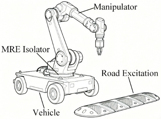
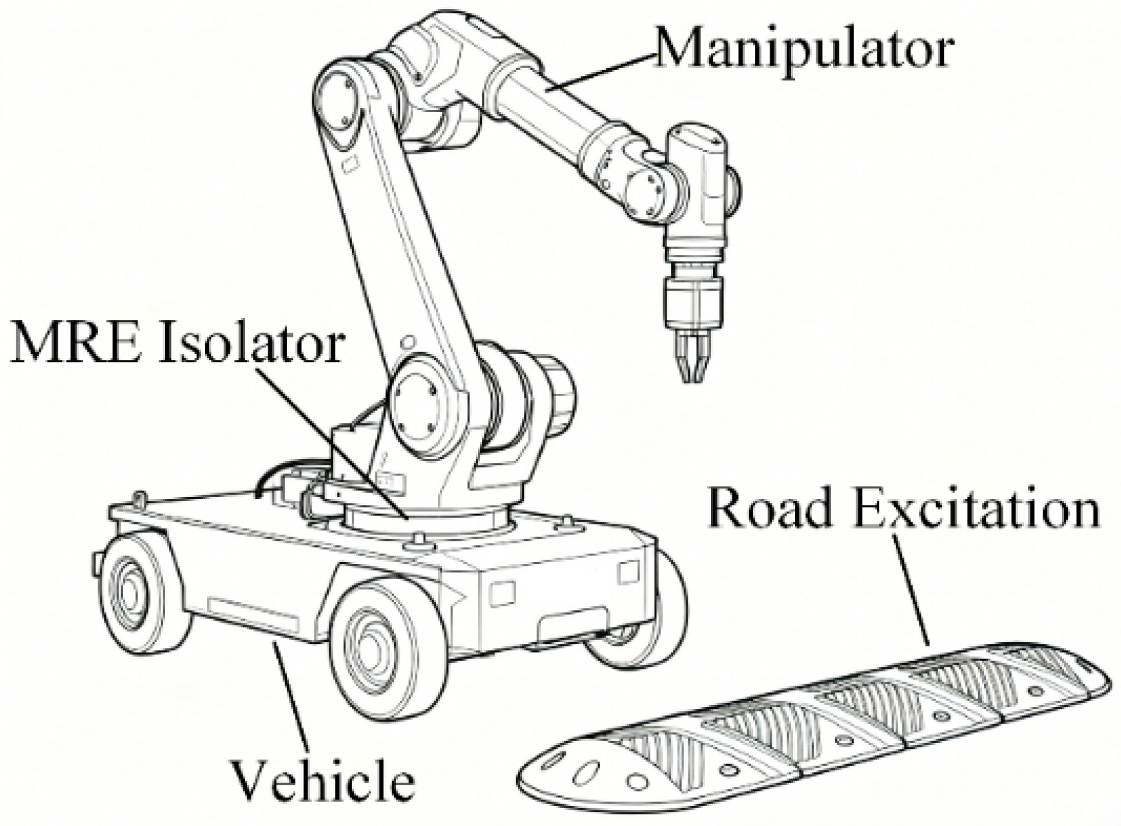
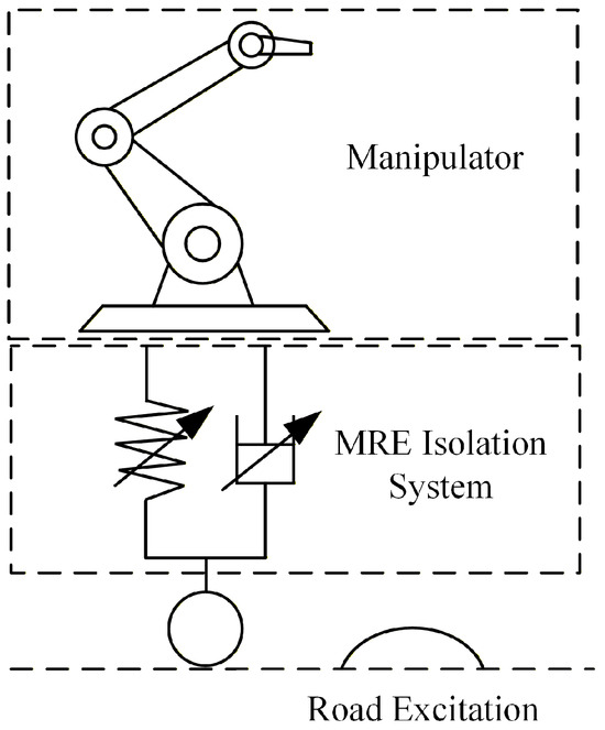
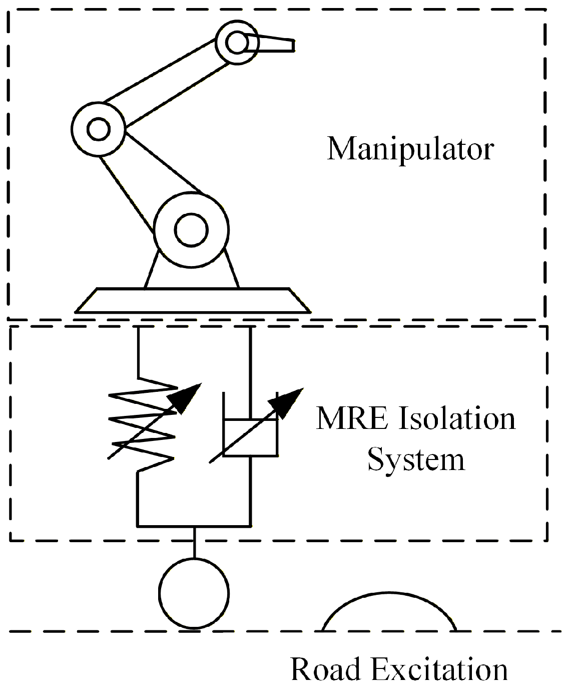
This paper takes the vehicle-mounted UR5e manipulator as an example to study the trajectory tracking control of the mobile manipulator under impact ground excitation. The mobile manipulator system studied in this paper consists of two main components: a mobile platform that provides translational mobility and a six-degree-of-freedom industrial manipulator (Universal Robots UR5e) mounted on the platform, as shown in Figure 1.
Figure 1.
Mobile manipulator.
The vehicle moves within the working environment and is modelled as a single-degree-of-freedom vertical oscillating system because its vertical vibrations dominate when traversing uneven surfaces (such as speed bumps). The vehicle carries the manipulator and other attachments, constituting the total load supported by a suspension or vibration isolation system. When subjected to external disturbances from the ground, the vehicle experiences vertical acceleration, which propagates upwards to the manipulator, thus becoming the primary source of external vibrations and trajectory deviations.
The Universal Robots UR5e is a lightweight collaborative manipulator widely used in industrial and scientific research fields due to its high repeatability, smooth dynamics, and flexible configuration. The UR5e manipulator features six revolute joints arranged in a typical 6R kinematic configuration. Joint 1 is the base rotation joint (lowest), Joints 2 and 3 control the shoulder and elbow for positioning, while Joints 4, 5, and 6 control the wrist orientation (with Joint 6 being the end-effector mounting joint). This configuration enables full spatial manipulation capability. The lightweight design of UR5e manipulator improves safety and energy efficiency, but also makes it more susceptible to disturbances from the vehicle. Even small base oscillations can cause measurable displacements in the end-effector due to dynamic coupling on the manipulator. The high precision requirements (±0.03 mm repeatability) of UR5e manipulator highlight the necessity of suppressing disturbances caused by impacts from the moving base. When the moving base oscillates vertically, the UR5e manipulator, rigidly mounted on the vehicle, is excited by the vehicle, and this excitation enters the nonlinear dynamic model of the manipulator as an external disturbance. The general dynamic model of the UR5e manipulator can be expressed as,
where denote the joint positions, velocities, and accelerations, M(q), and G(q) are the inertia, Coriolis, and gravity components. τ and τd are the joint control input and the disturbance torque induced by the base vibration, respectively. In practice, modeling errors, friction uncertainties, sensor noises, and external disturbances always exist. These uncertainties are collectively regarded as unmodeled dynamics.
Vertically transmitted displacement zb(t) produces an equivalent disturbance force at the manipulator’s base, which is mapped to the joints as,
where J(q) is the manipulator Jacobian. mr is the mass of the UR5e manipulator.
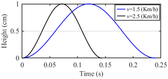
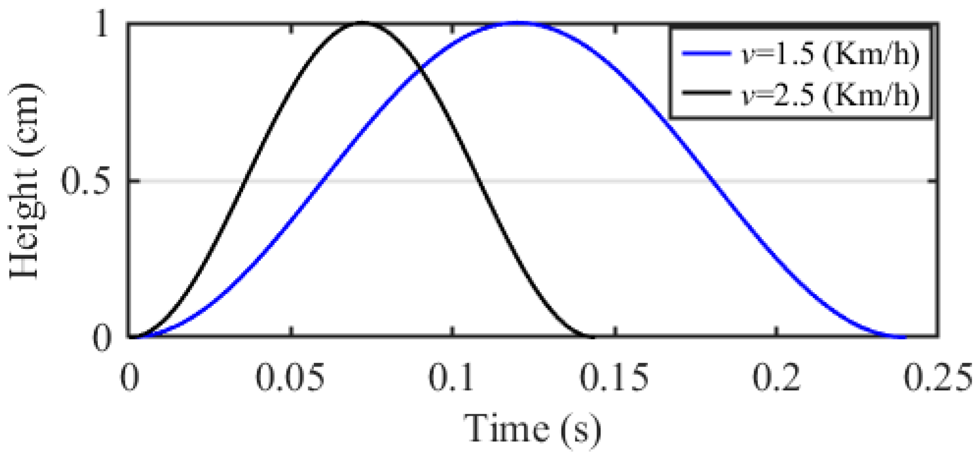
This coupling mechanism explains why small road excitation produces disproportionately large end-effector deviations, especially for mobile collaborative manipulators. The disturbance considered in this work originates from vehicle passing over speed bumps. This excitation is modeled as a discrete impact road excitation, which can be written as,
where h, l and v are the height, length of bump and vehicle speed, respectively. The speed bump used in this paper has a height of 10 mm and a width of 10 cm. The simulated vehicle speeds are 1.5 km/h and 2.5 km/h, as illustrated in Figure 2.
Figure 2.
Speed bump excitation under different speeds.
This input generates a strong, short-duration, wide-frequency vertical impact, significantly disturbing the motion trajectory of the UR5e manipulator. The interaction between the vehicle, the speed bump excitation, and the UR5e manipulator causes severe vertical vibration of the moving base, which is then transmitted to the manipulator through rigid connections. This results in a significant increase in joint tracking error and end-effector deviation, reducing operational accuracy. Therefore, the core problem to be solved in this study is how to simultaneously suppress base vibration and ensure high-precision trajectory tracking performance of the UR5e under the strong perturbation caused by impact excitation.
3. MRE Vibration Isolation System
To suppress the vertical vibration of the mobile manipulator and ensure its trajectory accuracy, this paper develops a semi-active isolation system-based MRE, as shown in Figure 1. The semi-active MRE isolator is placed between the vehicle and the UR5e manipulator to reduce the transmission of vibration caused by road surface excitation to the manipulator. Passive vibration isolation systems have been widely proven to suppress vibration transmission, but they are usually designed for specific loads and have poor adaptability [26]. The MRE isolator is a semi-active isolation device based on smart materials. It can adjust its hardness in real time according to the external vibration conditions to achieve the best vibration isolation effect. It has the advantages of real-time controllability, rapid response, low energy consumption, and strong adaptability. For the instantaneous and severe impact of the mobile manipulator passing over a speed bump, the MRE isolator can quickly adjust its stiffness and damping within milliseconds to absorb and dissipate the impact energy.
3.1. Design Principle
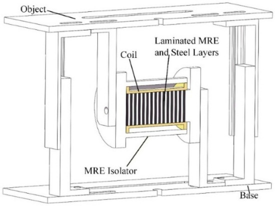
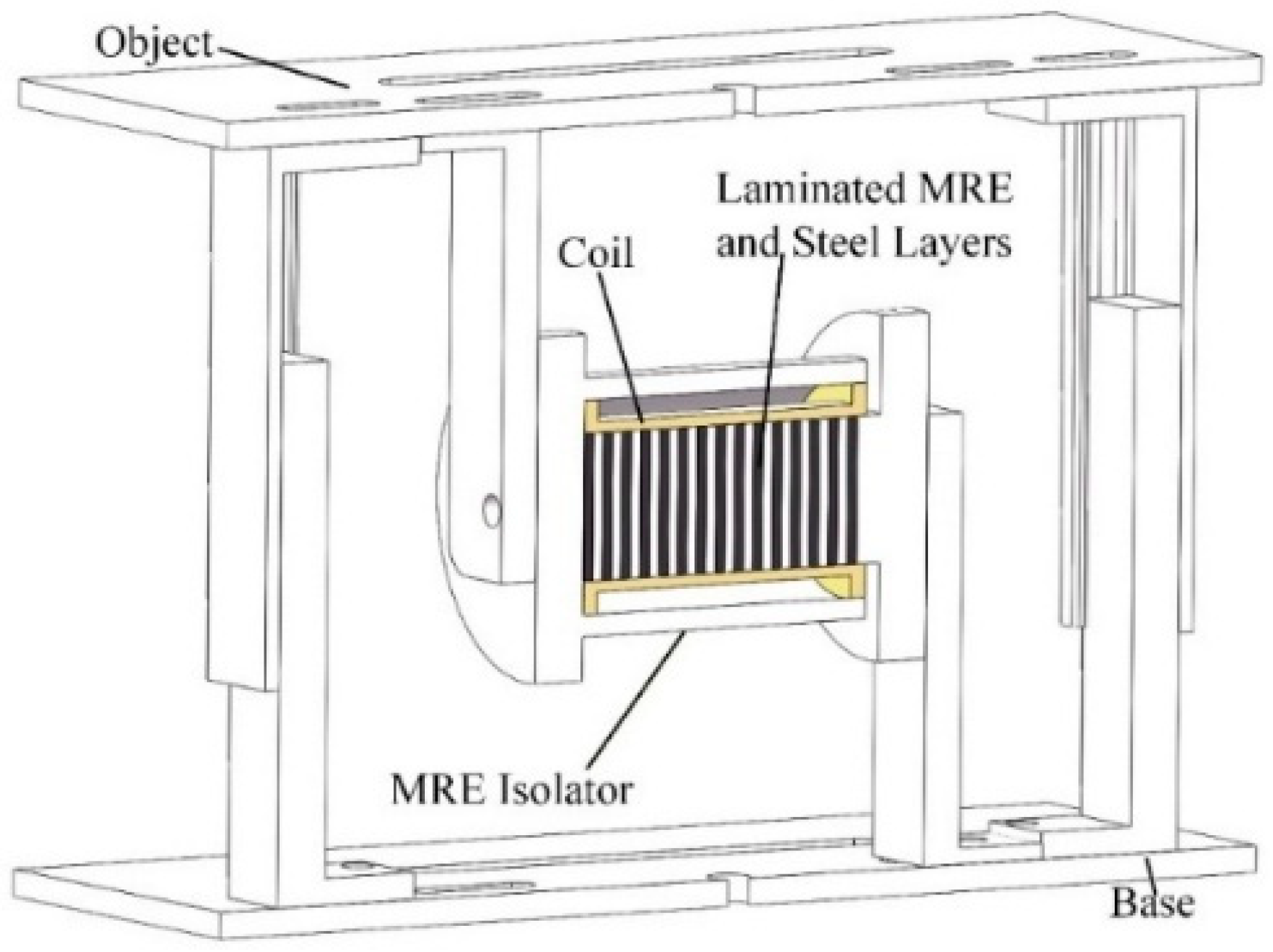
The MRE isolator mainly consists of a shell, coils, and an MRE/silicon steel sheet laminate. The performance of the MRE/silicon steel sheet laminate plays a key role in the overall performance of the MRE isolator, as shown in Figure 3. To fully utilize the performance of the MRE isolator, the parameters of the MRE/silicon steel sheet laminate need to be designed according to the specific conditions of the mobile manipulator. The specific process is as follows:
Figure 3.
Cross-sectional view of MRE isolator.
- (i)
- Determine the vertical load-bearing capacity of the MRE isolation system (weight of the UR5e manipulator) and the fundamental frequency of the impact load.
- (ii)
- Plan the layout of the MRE isolator and the number of isolators (one transversely arranged isolator is used in this study).
- (iii)
- Calculate the target stiffness required for the isolator based on the parameters of (i) and (ii). The shear stiffness can be obtained as follows,where W is the deck mass, g is the gravitational acceleration, and TH is the vertical natural period.
- (iv)
- Based on the inherent properties and target stiffness of the MRE material, the specific geometric dimension of the MRE material is determined. The thickness (HV) and diameter (d) of a single-layer MRE material can be obtained.where Vx is the interlaminar displacement, γ is the maximum allowable shear strain, generally taken as 20% [25].
3.2. MRE Isolator Fabrication and Characterization
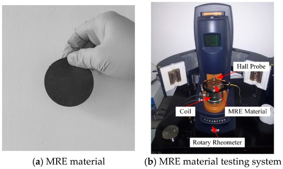
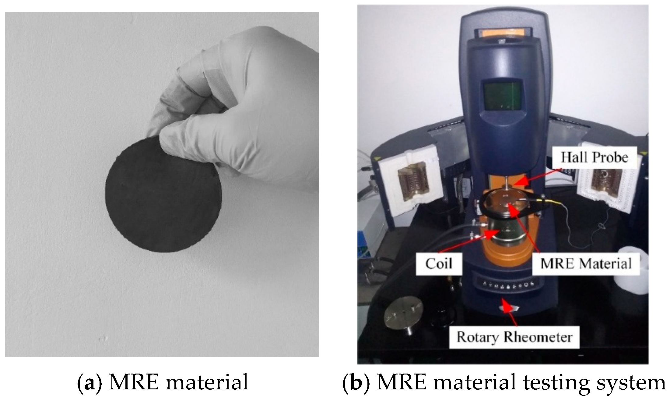
The performance of the MRE/silicon steel sheet laminate depends on the shear modulus (G) of the MRE material. Based on the characteristics of a mobile manipulator under impact loads, the MRE material required in this paper should possess a low initial shear modulus and strong magnetorheological effect. To address this characteristic and the designed MRE/silicon steel sheet laminate parameters, a new formulation was used to prepare the MRE material, and its mechanical properties were tested. The MRE material consists of three basic components: ferromagnetic particles, a rubber matrix, and additives (usually silicone oil), each with a specific weight ratio. The preparation of the MRE requires mixing the ferromagnetic particles and the rubber matrix, followed by vacuuming and magnetic curing. The completed MRE material is shown in Figure 4a.
Figure 4.
MRE material preparation and testing.
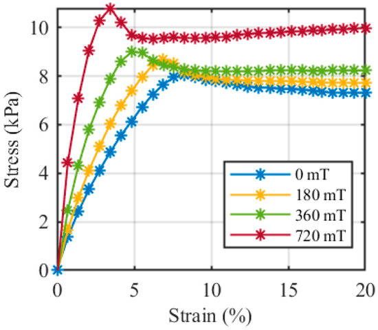
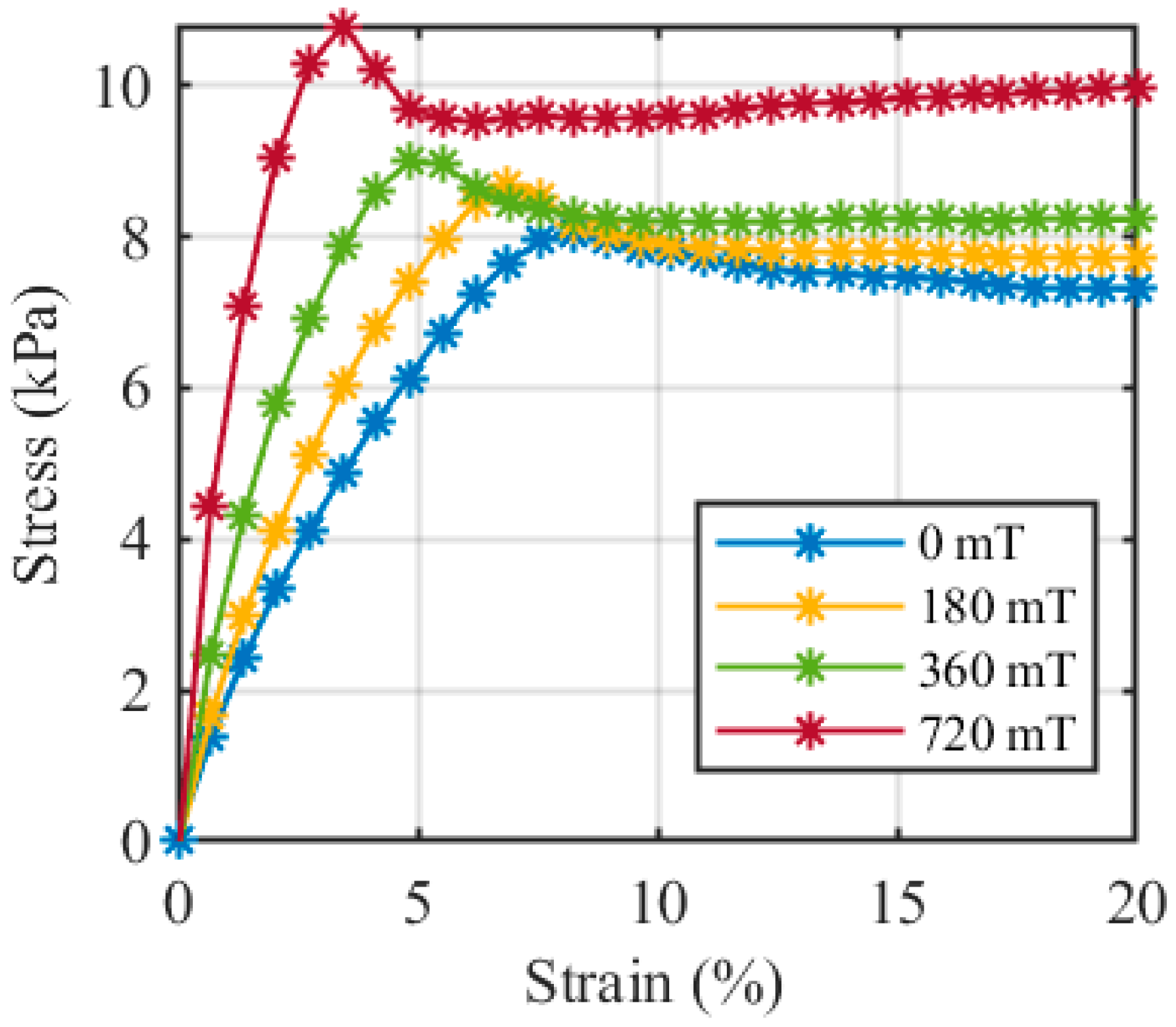
To more accurately characterize the magnetorheological effect of MRE materials, this paper uses a rotational rheometer (HR10 type) to test the static properties of MRE materials under shear mode. The test system is shown in Figure 4b. The MRE sample is placed on the rheometer chassis, and the coil at the bottom of the chassis provides the required varying magnetic field (range 0–0.72 T). The rotating rotor provides shear force to the MRE sample, causing shear displacement. The stress and strain of the MRE sample under shear state can be obtained through the data acquisition system, thereby calculating the shear modulus of the MRE sample, as shown in Figure 5.
Figure 5.
Stress–strain curves of MRE materials under different magnetic fields.
As can be seen from Figure 5, under the same shear strain, the shear modulus of the MRE material increases with the increase in magnetic field strength. However, when the shear strain exceeds a certain level, the shear stress of the MRE material decreases rapidly and tends to stabilize. This is because under large strain, the interaction force between particles inside the MRE material decreases due to the increase in spacing. This phenomenon is also known as the Payne effect [30]. The magnetorheological effect of the MRE material used in this paper can reach up to 500%; in the range of 0 mT to 720 mT, the shear modulus G increases from 0.12 MPa to 0.6 MPa. Based on the design principles of MRE isolator and the properties of MRE materials, the MRE isolator was developed.
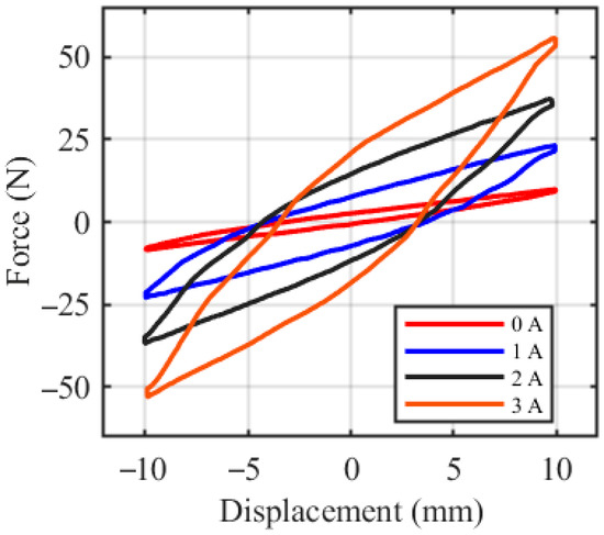
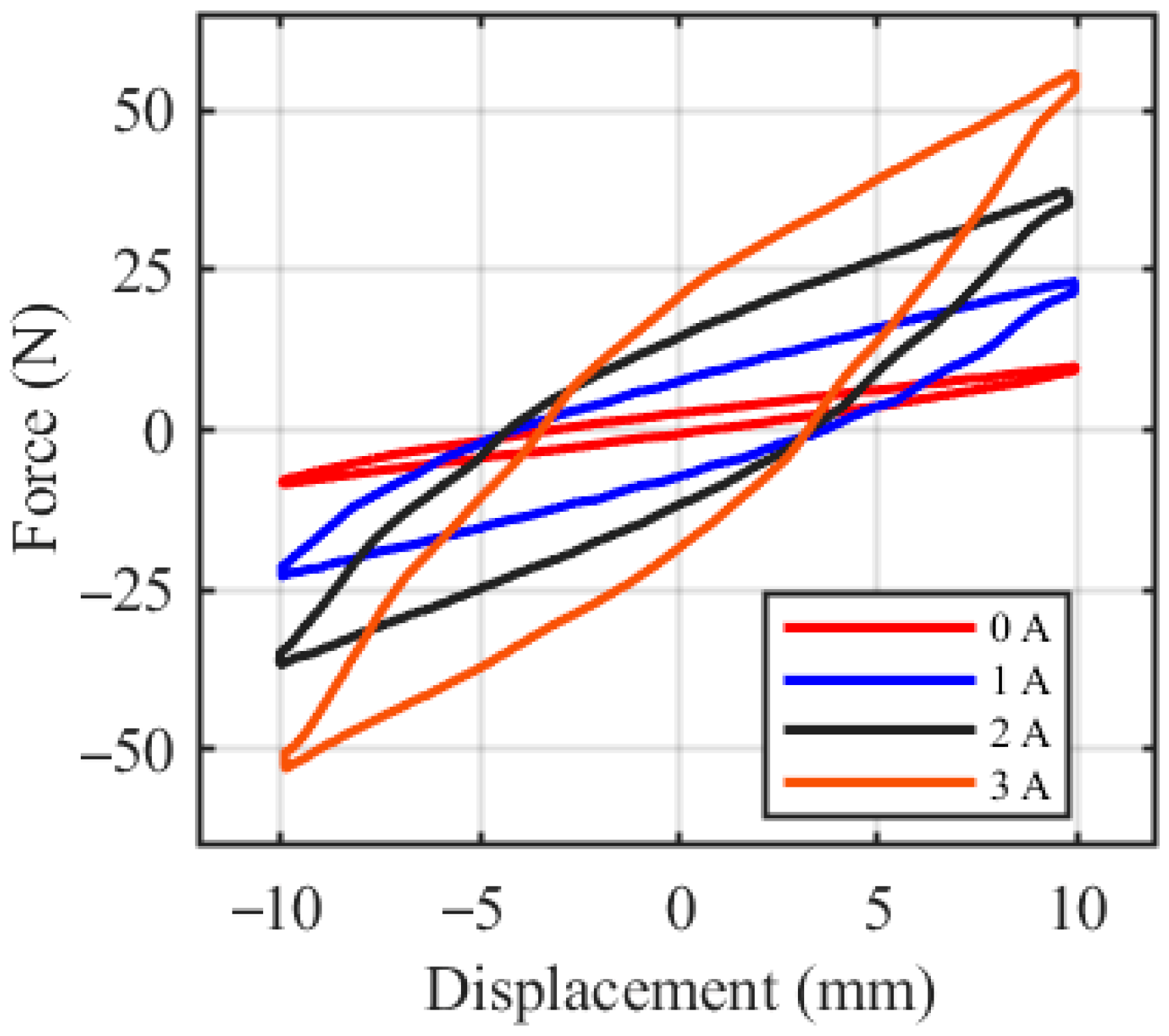
To obtain the practically controllable mathematical model of the proposed MRE isolator, a systematic mechanical performance test was conducted on the MRE isolator under the conditions of a shear displacement of ±10 mm and a sinusoidal excitation frequency of 2 Hz, as shown in Figure 6. The MRE isolator was tested under input currents of 0 A, 1 A, 2 A, and 3 A, which correspond to magnetic field strengths of approximately 0 mT, 240 mT, 480 mT, and 720 mT, respectively. As the current increases, the magnetic field strengthens, leading to higher stiffness and damping of the MRE isolator. The shear strain of the MRE isolator lags the shear stress, forming a phase difference. The slope of the ellipse represents the stiffness characteristic of the MRE isolator, and the enclosed area shows the energy dissipation throughout the process, representing the damping characteristic of the MRE isolator.
Figure 6.
Force–displacement curves of MRE isolator.
From Figure 6, the equivalent stiffness and damping of the MRE isolator both increase with increasing current. Based on the test data of the isolator, we select the Kelvin model to describe the dynamic characteristics of the MRE isolator. The Kelvin model can be written as,
where x(t) and are the displacement and velocity of the MRE isolator, respectively; k(I) and c(I) are the stiffness, damping components with input current I. The stiffness and damping components k(I) and c(I) can be written as,
where k1, k0 and c1, c0 are both unknown parameters that need to be identified. Based on the data measured in Figure 6, the Genetic Optimization (GA) algorithm was used to identify the unknown parameters in the Kelvin model. The specific values are shown in Table 1. Therefore, stiffness and damping coefficient under the different current can be obtained as listed in Table 2.
Table 1.
The parameters of Kelvin model.
Table 2.
Stiffness and damping coefficient under different currents.
3.3. Semi-Active Controller Design
Due to the inherent strong nonlinearity and uncertainty of MRE isolators, real-time control of MRE isolators is a challenge in practical engineering applications, and the quality of the controller directly determines the performance of the vibration isolation system. Since the excitation in this paper is a short-term impact-type low-frequency disturbance, the primary task of the MRE isolator is to maintain the lowest possible equivalent stiffness, keeping the system’s natural frequency away from the dominant excitation frequency band. Damping should only be temporarily increased to dissipate kinetic energy when significant relative velocity and energy accumulation are detected. Therefore, in selecting the semi-active control strategy, this paper ultimately adopts an ON-OFF control algorithm based on the Skyhook concept. ON-OFF control is designed around this physical mechanism: when the vehicle speed and the relative speed of the MRE isolator have the same sign, it switches to a high-damping state (I = 3 A), and maintains a low-stiffness, low-damping state (I = 0 A) at other times, thus achieving an adaptive trade-off between vibration isolation and energy dissipation.
4. Trajectory Tracking Control of the Manipulator
MRE isolation systems struggle to completely eliminate disturbances in the manipulator caused by road excitation. Therefore, the trajectory tracking control was adopted while retaining the MRE isolation system. Since the manipulator operates on a platform excited by discrete road bumps, the resulting base motion induces disturbance torques at all joints. Therefore, the control design must simultaneously achieve accurate model–based compensation and strong robustness against unknown disturbances. In manipulator trajectory tracking control, the CTC + PD control strategies are widely used due to its simple structure and ease of implementation. However, traditional CTC + PD methods heavily rely on accurate dynamic models of the system. In practical applications, model uncertainties, external disturbances, and parameter variations can significantly degrade system performance. To overcome these issues, this Section proposes an enhanced CTC + PD controller based on a predefined-time DOB. This design ensures that the disturbance estimation error converges within a predefined time window while maintaining stability and avoiding excessive amplification of noise at the initial stage.
Let , , and denote the desired joint trajectory obtained from iterative inverse kinematics corresponding to a Cartesian circular path. Based on the joint–space dynamic model already presented in Equation (1), the tracking errors and are defined. The desired joint acceleration used by the controller is,
where Kp and Kd are positive definite gain matrices. In the absence of disturbances, the nominal torque can be written as,
The nominal torque would recover the classical linear error dynamics and guarantee exponential convergence. However, when the manipulator is subjected to road excitation, the actual system dynamics contain an unknown disturbance torque . The achieved control torque incorporates the disturbance estimate generated by the observer, as shown below.
Substituting control torque into the dynamic equation yields the closed-loop error system. The closed-loop error system can be written as,
where is the observer estimation error. Therefore, the ultimate tracking accuracy directly depends on the convergence behavior of , and thus a properly designed DOB is essential.
To facilitate disturbance estimation, the disturbance torque is first expressed in an explicit form based on the system dynamics. From Equation (1), the disturbance can be interpreted as the mismatch between the actual system dynamics and the nominal model, which can be written as
In practice, is not directly measurable and is reconstructed using available state measurements and control inputs. Based on this formulation, a DOB is designed to estimate .
The observer used in this paper can be described as,
where the ω(t) is the time-varying activation gain, which can be given as,
where is a user-defined predefined time. This observer structure corresponds to first-order estimation dynamics driven by the reconstruction of disturbance torque. Therefore, the observer operates with low gain in the initial stage, avoiding the amplification of modeling uncertainties and measurement noise, and progressively increases its effectiveness until reaching full bandwidth at . The convergence properties are derived under a standard assumption.
Assumption 1
(Bounded rate of disturbance variation).
The disturbance torque satisfies
where is finite. This condition is reasonable in the present application, as the vehicle-induced excitations have bounded frequency and amplitude.
Letting , the error dynamic satisfies
The following conclusion can be drawn.
Lemma 1
(Predefined-time disturbance error attenuation).
Under Assumption 1, the estimation error satisfies
For , the observer exhibits exponential decay:
Proof.
The error dynamics in Equation (18) form a linear first-order nonhomogeneous differential equation. Using the variation of constants formula, the solution is given by,
Taking the norm and applying Assumption 1 yields:
Since with and , the integral in the first term satisfies . For the second term, note that , hence , which given:
However, a tighter bound can be obtained by noting that for , , and the inequality reduces to the exponential decay form in Equation (20). The integral of the activation function is strictly increasing over and equals at the predefined time, ensuring a guaranteed degree of error attenuation before exponential decay commences for .
After determining the convergence of the DOB, the standard Lyapunov function is used to test the stability of the entire closed-loop system, as shown in the following formula.
Since is skew-symmetric, we can obtain that,
Applying Young’s inequality,
Then we can get,
Substituting the bound from Lemma 1 establishes the main result.
Theorem 1
(Uniform ultimate boundedness and stability).
With the DOB defined above, the tracking error of the manipulator satisfies
where . If the disturbance varies slowly () and the observer bandwidth is sufficiently large, the closed-loop tracking error converges asymptotically to zero.
Proof.
The inequality for shows that decreases except for a bounded residual term determined by . Lemma 1 ensures that is uniformly ultimately bounded with an upper bound proportional to . Standard Lyapunov arguments then imply uniform ultimate boundedness of and , and asymptotic convergence follows when .
The proposed predefined-time DOB involves two key parameters: the predefined convergence time and the final observer gain . Proper selection of these parameters is crucial for achieving satisfactory disturbance estimation performance.
The parameter defines the time window within which the disturbance estimation error converges to a small neighborhood. A smaller yields faster convergence but may amplify measurement noise due to the rapid increase in the activation gain . A larger provides smoother estimation at the cost of delayed disturbance compensation. In practice, should be chosen to be smaller than the dominant time constant of the closed-loop system to ensure timely rejection of disturbances. In this study, s is selected, which is sufficiently smaller than the manipulator’s dominant dynamics (approximately 0.5 s) while maintaining acceptable noise sensitivity.
The final gain determines the exponential convergence rate for and also affects the ultimate bound of the estimation error, as shown in Lemma 1. From Equation (20), the steady-state error is bounded by . Therefore, a larger leads to smaller steady-state error and faster convergence. However, excessively large may amplify high-frequency measurement noise. The selected value in this study provides a trade-off between estimation accuracy and noise suppression, which is sufficient for the considered impact excitation frequencies (dominant components below 10 Hz).
This analysis demonstrates that the proposed CTC + PD controller, enhanced with a predefined-time DOB, guarantees stable and robust trajectory tracking for the manipulator under base-induced disturbances. The observer ensures that disturbance estimation rapidly becomes accurate after a predefined transition period, while the PD-based error feedback and inverse-dynamics compensation maintain overall system stability. This forms a reliable control foundation for the multibody dynamics coupling analysis presented in Section 5.
5. MRE Isolation System
To evaluate the effect of the MRE intelligent isolation system on the operational accuracy of the mobile manipulator under continuous ground impact loads, this paper models the mobile platform, intelligent vibration isolation system, and six-degree-of-freedom manipulator as a dynamically coupled multibody system. While the dynamics and control strategies of the vehicle base, MRE isolators, and manipulators have been discussed separately, the coupling between ground excitation, the semi-active MRE isolation system, and the controlled manipulator has not been systematically analyzed. These components together constitute a complex multibody system with strongly coupled dynamics. The purpose of this section is not to describe the detailed structure of the isolators or excitation mechanisms, but rather to establish a unified nonlinear dynamic model to characterize how external vertical disturbances propagate through the platform and ultimately affect the joint dynamics of the manipulator.
Figure 7 shows a multibody system under the action of road excitation. Under continuous seismic impact loads, the multibody dynamic model of the MRE intelligent isolation system can be written as,
where is the apparent Cartesian inertia in the vertical direction, and are the vertical Coriolis/centrifugal wrench and the gravitational wrench.
Figure 7.
Multibody system under the action of road excitation.
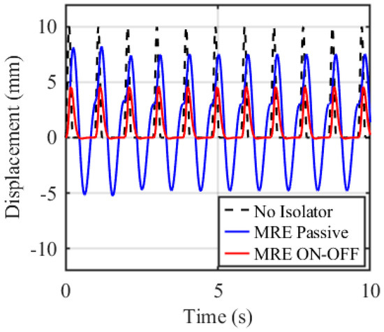
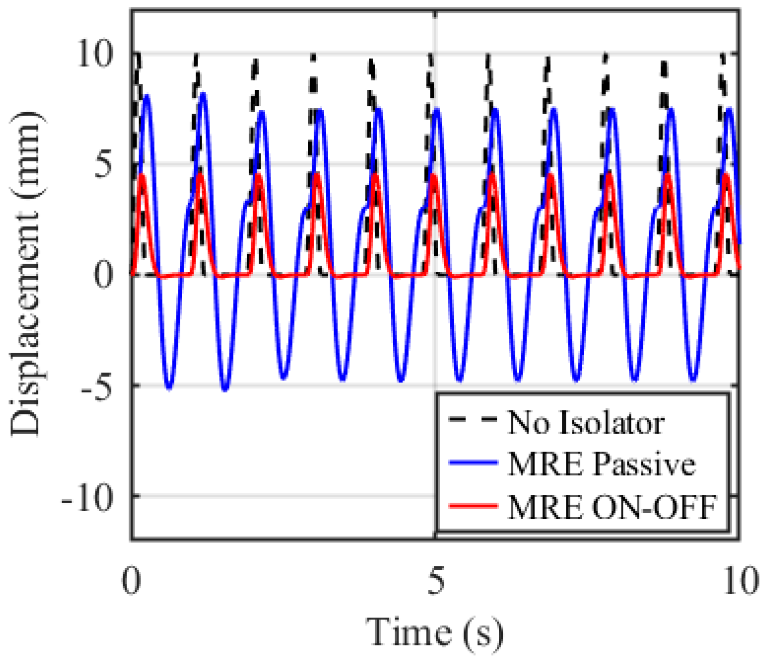
To evaluate the effect of the MRE intelligent isolation system on the operational accuracy of the mobile robotic arm under continuous impact loads, continuous ground bump excitation (10 mm high, 100 mm wide, 20 bumps, spaced 300 mm apart), the MRE intelligent isolation system (parameters see Section 3), and the UR5e manipulator (weight 20.6 kg) were considered. Figure 8 shows the vibration reduction effect of different isolation schemes at a mobile manipulator speed of 1.5 km/h.
Figure 8.
Vibration reduction effect of different isolation schemes.
As shown in Figure 8, without the MRE isolation system, the ground impact load is directly transmitted to the bottom of the UR5e manipulator, resulting in an amplitude of 10 mm. When the MRE isolator adopts a passive vibration isolation method, that is, without the input of control current, the MRE isolator relies solely on its own structural characteristics for passive vibration isolation, and the MRE isolator still achieves good anti-vibration performance. In the passive state, the disturbance amplitude at the bottom of the manipulator is 7.5 mm, a 25% reduction compared to the state without an isolator. The best performance is achieved with the semi-active MRE isolation system. Under ON-OFF control, the MRE fully utilizes its variable stiffness and damping characteristics, resulting in a disturbance amplitude of only 4.5 mm at the bottom of the manipulator, a 55% and 40% reduction compared to the state without an isolator and the passive isolator, respectively. This lays a solid foundation for precise control of the manipulator’s end-effector trajectory.
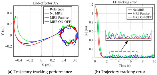
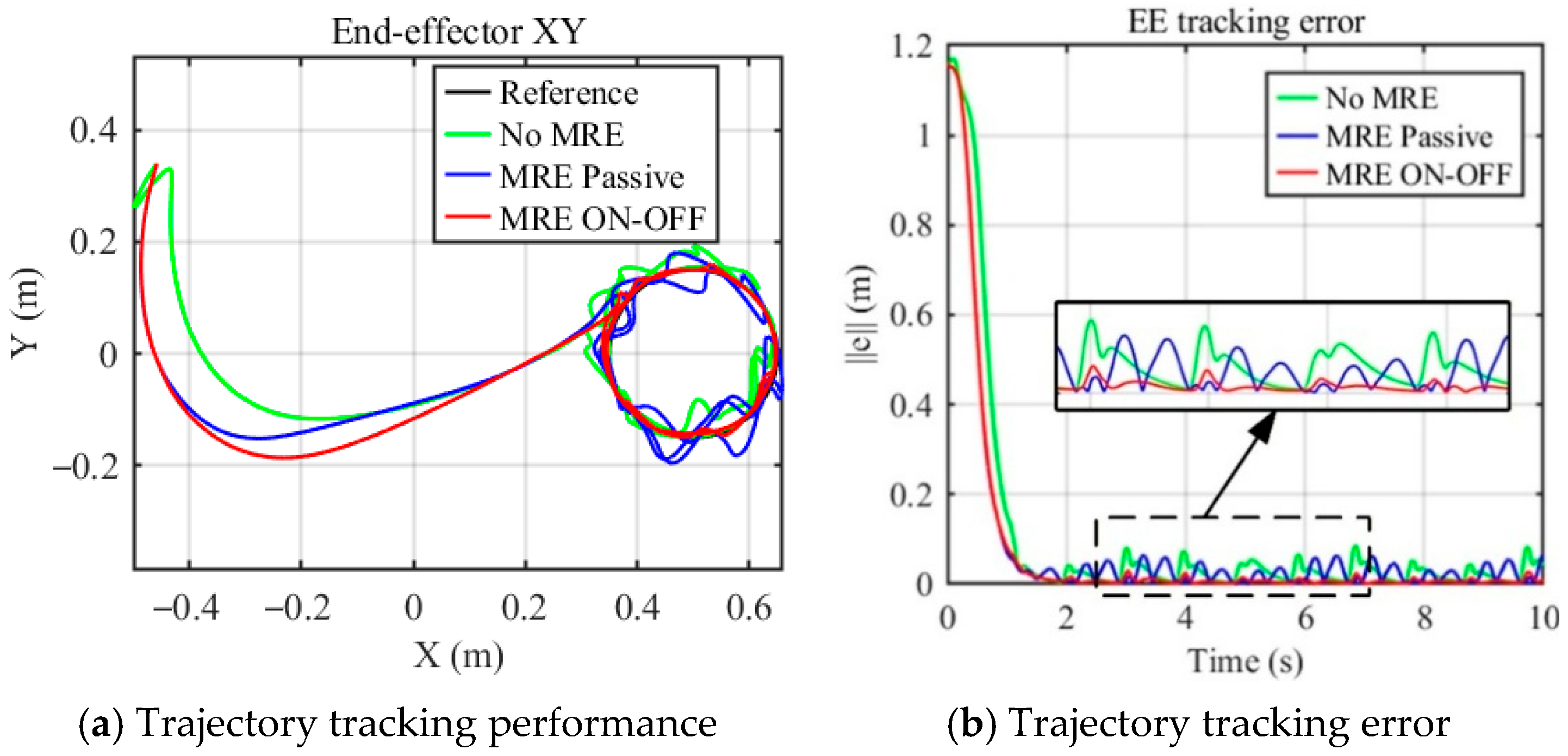
To analyze the end-effector trajectory tracking accuracy of the mobile UR5e manipulator coupled with the MRE intelligent isolation system, a trajectory tracking control algorithm based on the CTC + PD framework with a predefined-time DOB under a circular reference trajectory was further simulated and analyzed. Figure 9 shows the end-effector trajectory tracking effect and tracking error under different vibration isolation methods.
Figure 9.
Trajectory tracking of end-effector under different vibration isolation methods.
Figure 9 illustrates the trajectory tracking performance and tracking error of the end-effector of UR5e manipulator under different anti-vibration methods. As can be seen from Figure 9, under the CTC + PD controller with a predefined-time DOB, the MRE intelligent isolation system proposed in this paper can significantly improve the accuracy of the end-effector in ON-OFF control. The maximum trajectory tracking errors of the end-effector in steady state (2 s–10 s) are 0.0867 m, 0.0651 m, and 0.0301 m for the mobile manipulator without an isolator, with a passive MRE isolator, and with a semi-active MRE isolator, respectively. Compared with the state without an MRE isolator, the maximum tracking errors in the passive and semi-active control states are reduced by 24.91% and 65.28%, respectively. The root mean square (RMS) values of the tracking errors are reduced by 8.98% and 73.07%, respectively, reflecting the overall stability during the tracking process. Clearly, under the same tracking control algorithm, the semi-active MRE isolation system with adjustable stiffness and damping has a significant improvement effect on the trajectory tracking control of the mobile manipulator under continuous impact road excitations.
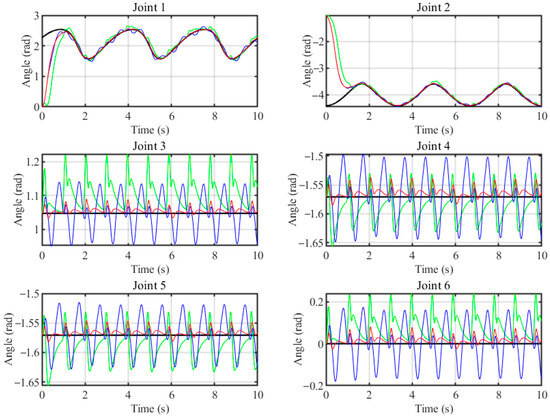
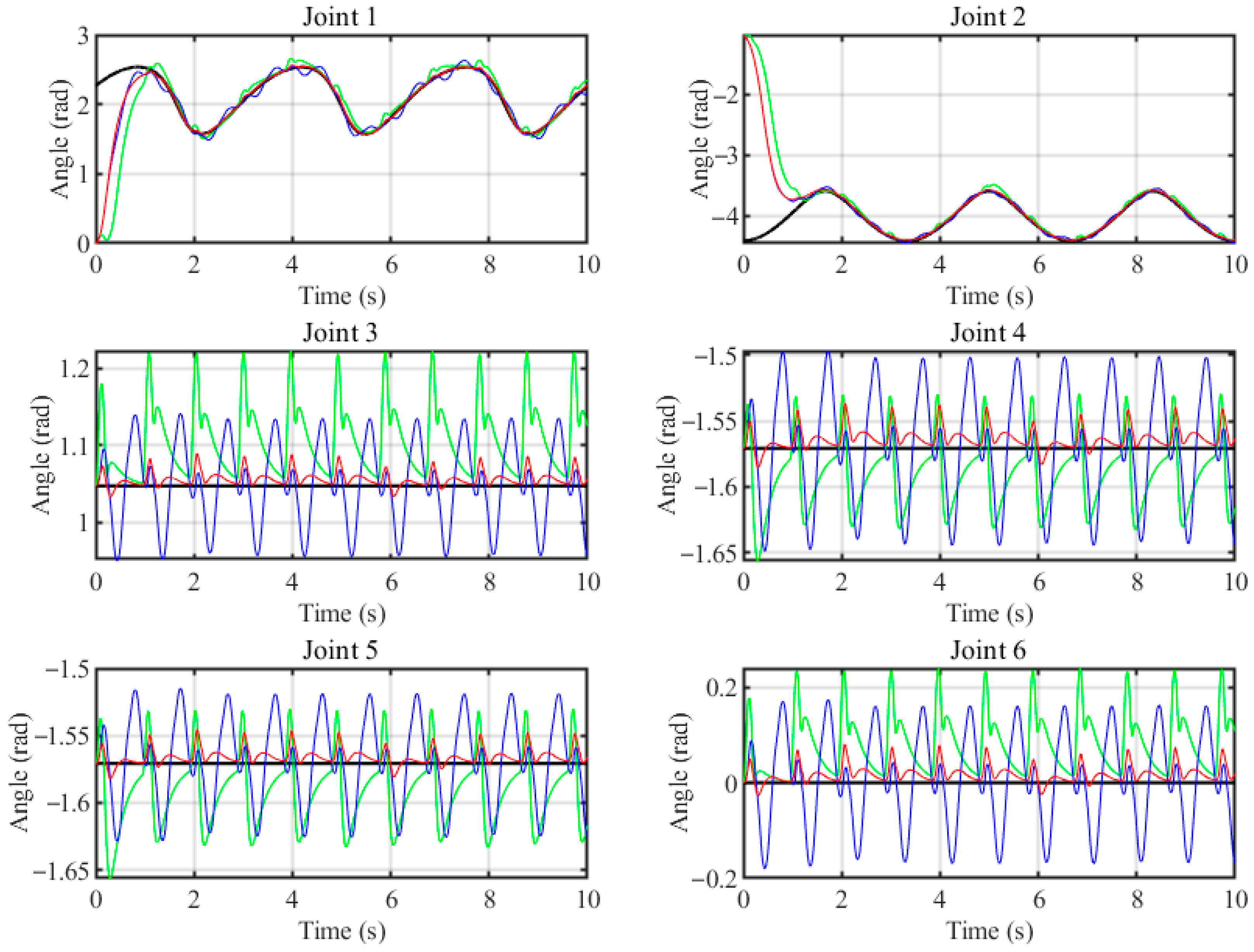
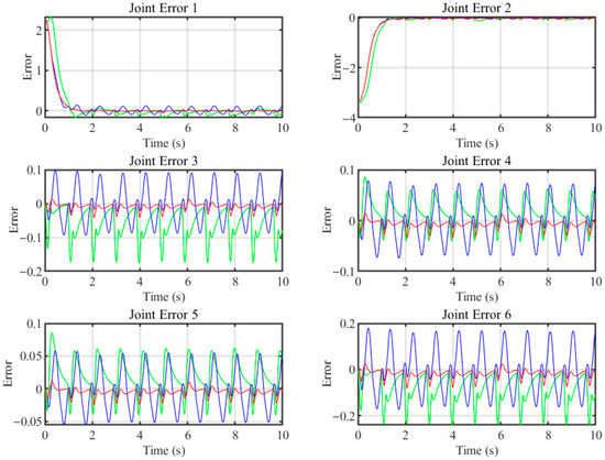
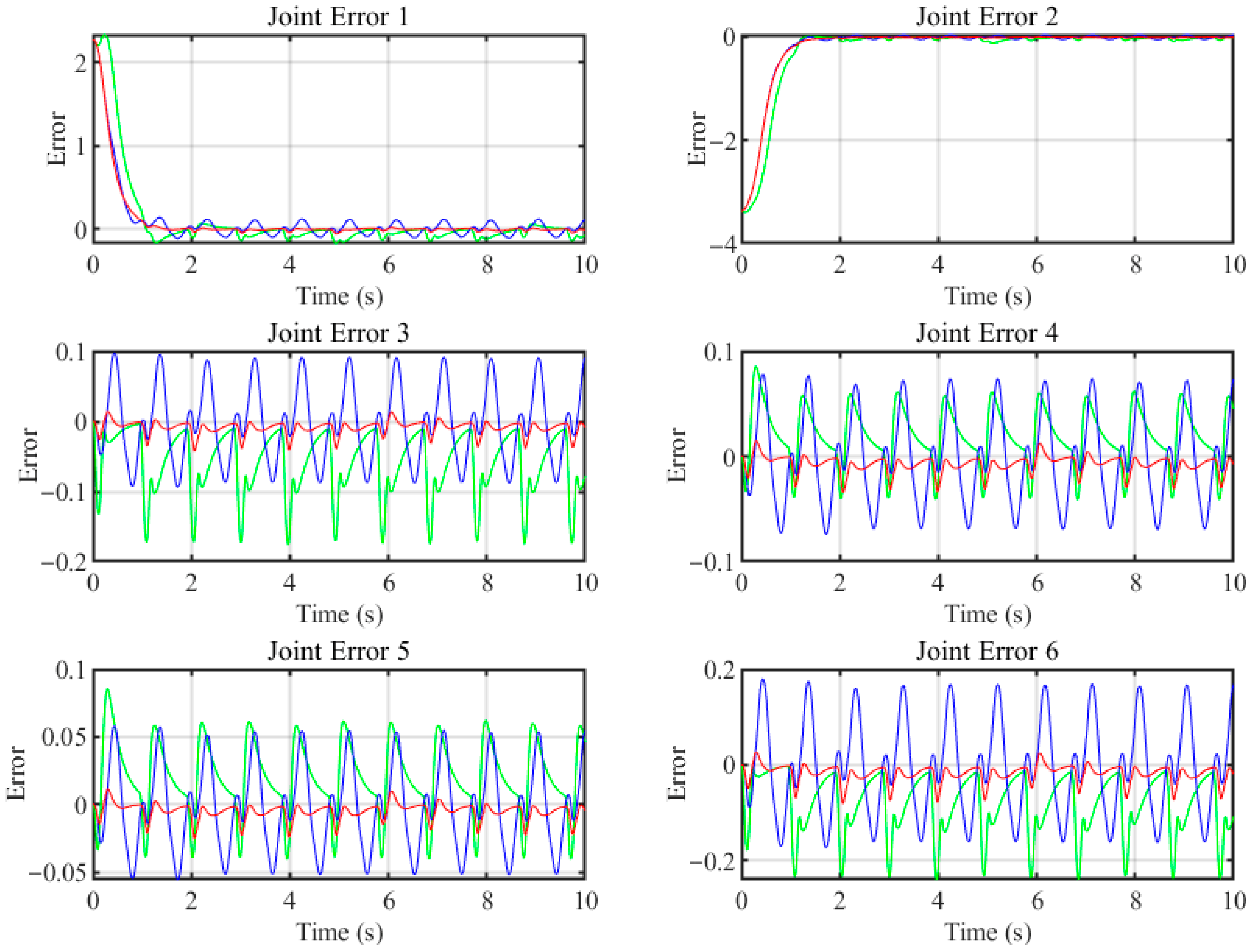
To further investigate the effect of the MRE isolation system on the trajectory tracking of the mobile manipulator, Figure 10 and Figure 11 show the tracking trajectories and tracking errors of the manipulator’s rotating joints under three vibration isolation conditions. From Figure 10 and Figure 11, it is clear that the MRE isolation system can significantly improve the trajectory tracking accuracy of each joint, even in the MRE passive state. For quantitative analysis, Table 3 lists the maximum and RMS values of the tracking errors of the end-effector and the 6 joints of the mobile manipulator under different isolation states. It also shows the reduction in trajectory tracking error compared to the absence of an MRE isolator.
Figure 10.
6-DOF joint trajectory tracking.
Figure 11.
6-DOF joint trajectory tracking error.
Table 3.
Comparison of Trajectory tracking error. [Steady state (after 2 s)].
From Figure 10 and Figure 11 and Table 3, the MRE isolation system yields remarkable improvements in the trajectory tracking performance of all six joints, consistent with the observed reductions in end-effector trajectory errors. For Joint 1, the maximum tracking errors in the steady-state interval are significantly reduced from the baseline value of 0.1777 rad, decreasing to 0.1179 rad in the passive state and 0.0600 rad in the ON–OFF semi-active state. These values correspond to 33.65% and 66.24% reductions, respectively. Similarly, the RMS tracking error is reduced from 0.0709 rad to 0.0630 rad (passive) and 0.0163 rad (ON–OFF), achieving reductions of 11.14% and 77.01%, respectively. For Joint 2, the passive MRE isolator reduces the maximum tracking error from 0.1211 rad to 0.0553 rad, achieving a 54.34% improvement. The ON–OFF semi-active control further reduces the error to 0.0347 rad, corresponding to an improvement of 71.35% relative to the no-isolator case. The RMS error also shows significant decreases: from 0.0415 rad down to 0.0279 rad (passive, 32.77% reduction) and to 0.0123 rad (ON–OFF, 70.36% reduction). Joint 3 also benefits significantly from MRE isolation. The maximum tracking error decreases from 0.1756 rad to 0.0918 rad (passive, 47.72% reduction) and further to 0.0422 rad (ON–OFF, 75.97% reduction). The RMS error improves correspondingly, decreasing from 0.0782 rad to 0.0520 rad (passive, 33.50% reduction) and to 0.0137 rad (ON–OFF, 82.48% reduction). This joint shows the largest RMS error reduction, highlighting the effectiveness of the semi-active MRE isolator in mitigating oscillations transmitted to higher-frequency joint motions.
For joint 4, the passive MRE isolator increased the tracking error (the maximum error increased from 0.0618 rad to 0.0738 rad, a change of −19.42%; the RMS error increased from 0.0325 rad to 0.0413 rad, a change of −27.08%). This is because the passive MRE isolator has low stiffness, which easily causes the manipulator to become unstable. However, semi-active control significantly reduced the maximum error and root mean square error to 0.0343 rad and 0.0115 rad, respectively, representing improvements of 44.50% and 64.62% relative to the baseline performance. This indicates that the semi-active control can adjust the stiffness of the MRE isolation system according to the motion state of the mobile manipulator, ensuring the real-time stability of the entire structure. For Joint 5, the maximum error is reduced from 0.0624 rad to 0.0548 rad under passive isolation (12.18% reduction) and to 0.0254 rad under ON–OFF control (59.29% reduction). The RMS value is reduced from 0.0327 rad to 0.0309 rad (passive, 5.50%) and to 0.0081 rad (ON–OFF, 75.23% reduction). Joint 6 exhibits considerable improvements as well. The maximum error decreases from 0.2399 rad to 0.1689 rad with passive isolation (29.60% reduction) and further to 0.0809 rad with ON–OFF control (66.28% reduction). These results reflect the same trend observed in other joints: semi-active control consistently outperforms the passive isolator.
Across all six joints, the semi-active (ON–OFF) MRE isolation system consistently achieves the largest reductions in both maximum and RMS tracking errors, often exceeding 70–80% improvement compared to the no-isolator baseline. Even the passive MRE isolator yields notable improvements for most joints, confirming that mitigating vibration transmission at the base directly enhances the manipulator tracking performance.
In addition, to evaluate the robustness of the proposed isolation system under different operating conditions, additional simulations were conducted at a speed of 2.5 km/h. The results show that, under the same semi-active MRE isolation system and CTC + PD controller with predefined-time DOB, the maximum end-effector tracking error is reduced from 0.1124 m (without isolator) to 0.0427 m, a reduction of 62.01%, while the RMS error is reduced from 0.0418 m to 0.0102 m, a reduction of 75.60%. These reductions are comparable to those observed at 1.5 km/h (65.28% and 73.07%, respectively), demonstrating that the proposed isolation system maintains consistent trajectory tracking performance across different travel speeds.
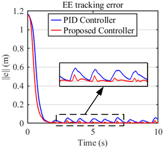
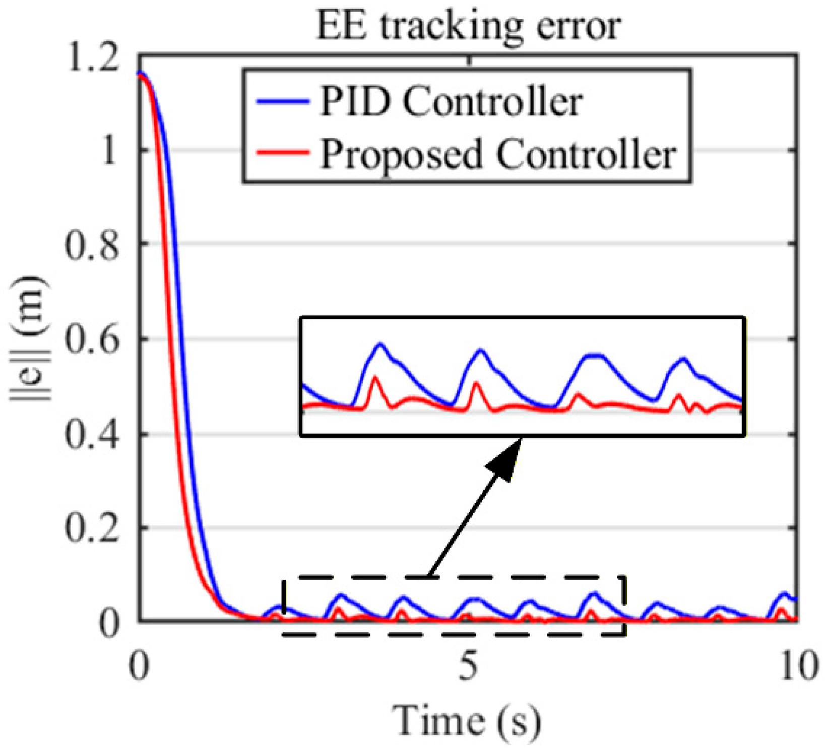
To further evaluate the effectiveness of the proposed CTC + PD controller with predefined-time DOB, a comparative study with traditional PID control was conducted under the same semi-active MRE isolation system with ON-OFF control. The PID gains were tuned to achieve optimal tracking performance. As shown in Figure 12, the proposed CTC + PD controller with predefined-time DOB achieves a maximum tracking error of 0.0301 m, compared to 0.0619 m for PID, representing a 51.37% reduction. The RMS error is reduced from 0.0300 m to 0.0087 m, a 71.00% improvement. These results demonstrate the superior disturbance rejection capability of the proposed controller.
Figure 12.
Trajectory tracking errors of the end-effector under different controllers.
6. Conclusions
This paper investigates the effect of a semi-active MRE intelligent isolation system on the trajectory tracking accuracy of a mobile manipulator under continuous road impact excitations, and explores the advantages of combining semi-active control with active trajectory tracking control. Based on the characteristics and application scenarios of the mobile manipulator, a multi-layer MRE isolation system was fabricated. Its variable stiffness characteristics were tested, and a semi-active controller was developed to control the stiffness and damping of the isolators in real time. The trajectory tracking control strategy for the UR5e manipulator was developed based on the CTC + PD framework with predefined-time DOB. The coupled dynamic model of an actual mobile manipulator equipped with the MRE intelligent isolation system was established, and the effect of different vibration isolation methods on tracking accuracy was compared and analyzed under the same manipulator trajectory tracking control algorithm.
Multibody co-simulation was used to verify the effectiveness of the proposed MRE intelligent isolation system in improving the trajectory tracking accuracy of the mobile manipulator. When a mobile manipulator traveling at 1.5 km/h passes through a series of speed bumps, the semi-active MRE isolation system reduced the maximum and average RMS values of the end-effector accuracy by 65.28% and 73.07%, respectively. The tracking performance of the manipulator’s rotating joints demonstrates that the MRE intelligent isolation system effectively avoids resonance by shifting the frequency of the mobile manipulator from the excitation frequency, while maintaining overall structural stability. Joint 3 showed the largest reduction in trajectory tracking error, with its maximum and RMS values decreasing by 75.975% and 82.48%, respectively, highlighting the effectiveness of the semi-active MRE isolator in suppressing vibrations transmitted to high-frequency joint movements. Compared with traditional PID control under the same conditions, the proposed CTC + PD controller with predefined-time DOB achieves a 51.37% reduction in maximum tracking error and a 71.00% reduction in RMS error, further demonstrating its superior disturbance rejection capability. In addition, the proposed anti-vibration system maintains consistent trajectory tracking performance across different speeds, achieving comparable vibration reduction effects at both 1.5 km/h and 2.5 km/h, thereby demonstrating its robustness to varying operating conditions.
These results validate that the proposed MRE isolation system, particularly in the semi-active configuration, substantially enhances the robustness and accuracy of trajectory tracking for mobile manipulators operating under continuous impact excitations. In addition, the proposed methodology is inherently generalizable to other mobile manipulator systems. The MRE isolation system can be redesigned for different manipulator masses using the design principle provided, while the semi-active control strategy adapts to varying load conditions without requiring recalibration. The DOB-enhanced CTC + PD controller is applicable to any serial manipulator with known dynamics, and the predefined-time observer compensates for disturbances regardless of the platform specifics.
Author Contributions
Conceptualization, data curation, investigation, methodology, validation, writing—original draft preparation, Z.Z.; resources, supervision, C.F.C.; writing—review and editing, supervision, Y.L. All authors have read and agreed to the published version of the manuscript.
Funding
This research was funded by the Research Impact Fund of Research Grants Council (Hong Kong) (Grant No. R5047-22).
Data Availability Statement
The original contributions presented in this study are included in the article. Further inquiries can be directed to the corresponding author.
Conflicts of Interest
The authors declare no conflicts of interest.
References
- Chen, J.; Xie, F.; Liu, X.-J.; Chong, Z. Elasto-Geometrical Calibration of a Hybrid Mobile Robot Considering Gravity Deformation and Stiffness Parameter Errors. Robot. Comput.-Integr. Manuf. 2023, 79, 102437. [Google Scholar] [CrossRef] [Scilit]
- Bhavanibhatla, K.; Suresh-Fazeela, S.; Pratihar, D.K. A Study on Determining Optimal Base Location of a Serial Manipulator Mounted on a Hexapod Mobile Robot. J. Braz. Soc. Mech. Sci. Eng. 2021, 43, 226. [Google Scholar] [CrossRef] [Scilit]
- Pankert, J.; Hutter, M. Perceptive Model Predictive Control for Continuous Mobile Manipulation. IEEE Robot. Autom. Lett. 2020, 5, 6177–6184. [Google Scholar] [CrossRef] [Scilit]
- Liu, M.; Tang, Q.; Li, Y.; Liu, C.; Yu, M. A Chattering-Suppression Sliding Mode Controller for an Underwater Manipulator Using Time Delay Estimation. J. Mar. Sci. Eng. 2023, 11, 1742. [Google Scholar] [CrossRef] [Scilit]
- Jia, S.; Shan, J. Velocity-Free Trajectory Tracking and Active Vibration Control of Flexible Space Manipulator. IEEE Trans. Aerosp. Electron. Syst. 2022, 58, 435–450. [Google Scholar] [CrossRef] [Scilit]
- Liu, J.; Zhao, P.; Chen, K.; Zhang, X.; Zhang, X. 1U-Sized Deployable Space Manipulator for Future On-Orbit Servicing, Assembly, and Manufacturing. Space Sci. Technol. 2022, 2022, 9894604. [Google Scholar] [CrossRef] [Scilit]
- Abbas, M.R.; Ahsan, M.; Iqbal, J. Experimental Development of Lightweight Manipulators with Improved Design Cycle Time That Leverages Off-the-Shelf Robotic Arm Components. PLoS ONE 2024, 19, e0305379. [Google Scholar] [CrossRef] [Scilit]
- Satya Durga Manohar Sahu, V.; Samal, P.; Kumar Panigrahi, C. Modelling, and Control Techniques of Robotic Manipulators: A Review. Mater. Today Proc. 2022, 56, 2758–2766. [Google Scholar] [CrossRef] [Scilit]
- Uyar, M.; Malgaca, L. Implementation of Active and Passive Vibration Control of Flexible Smart Composite Manipulators with Genetic Algorithm. Arab. J. Sci. Eng. 2023, 48, 3843–3862. [Google Scholar] [CrossRef] [Scilit]
- Azeez, M.I.; Abdelhaleem, A.M.M.; Elnaggar, S.; Moustafa, K.A.F.; Atia, K.R. Optimization of PID Trajectory Tracking Controller for a 3-DOF Robotic Manipulator Using Enhanced Artificial Bee Colony Algorithm. Sci. Rep. 2023, 13, 11164. [Google Scholar] [CrossRef] [Scilit]
- Wang, X.; Niu, B.; Zhao, X.; Zong, G.; Cheng, T.; Li, B. Command-Filtered Adaptive Fuzzy Finite-Time Tracking Control Algorithm for Flexible Robotic Manipulator: A Singularity-Free Approach. IEEE Trans. Fuzzy Syst. 2024, 32, 409–419. [Google Scholar] [CrossRef] [Scilit]
- Sun, Y.; Liu, J.; Gao, Y.; Liu, Z.; Zhao, Y. Adaptive Neural Tracking Control for Manipulators With Prescribed Performance Under Input Saturation. IEEE/ASME Trans. Mechatron. 2023, 28, 1037–1046. [Google Scholar] [CrossRef] [Scilit]
- Silaa, M.Y.; Barambones, O.; Bencherif, A. Robust Adaptive Sliding Mode Control Using Stochastic Gradient Descent for Robot Arm Manipulator Trajectory Tracking. Electronics 2024, 13, 3903. [Google Scholar] [CrossRef] [Scilit]
- Azeez, M.I.; Abdelhaleem, A.M.M.; Elnaggar, S.; Moustafa, K.A.F.; Atia, K.R. Optimized Sliding Mode Controller for Trajectory Tracking of Flexible Joints Three-Link Manipulator with Noise in Input and Output. Sci. Rep. 2023, 13, 12518. [Google Scholar] [CrossRef] [Scilit]
- Cao, S.; Sun, L.; Jiang, J.; Zuo, Z. Reinforcement Learning-Based Fixed-Time Trajectory Tracking Control for Uncertain Robotic Manipulators With Input Saturation. IEEE Trans. Neural Netw. Learn. Syst. 2023, 34, 4584–4595. [Google Scholar] [CrossRef] [Scilit]
- Wang, X.; Wang, D.; Du, M.; Song, K.; Ni, Y.; Li, Y. A Two-Layer Trajectory Tracking Control Scheme of Manipulator Based on ELM-SMC for Autonomous Robotic Vehicle. IEEE Trans. Autom. Sci. Eng. 2024, 21, 2337–2348. [Google Scholar] [CrossRef] [Scilit]
- Lee, T.S.; Alandoli, E.A. A Critical Review of Modelling Methods for Flexible and Rigid Link Manipulators. J. Braz. Soc. Mech. Sci. Eng. 2020, 42, 508. [Google Scholar] [CrossRef] [Scilit]
- Tian, X.; Xu, Q.; Zhan, Q. An Analytical Inverse Kinematics Solution with Joint Limits Avoidance of 7-DOF Anthropomorphic Manipulators without Offset. J. Frankl. Inst. 2021, 358, 1252–1272. [Google Scholar] [CrossRef] [Scilit]
- Pistone, A.; Ludovico, D.; De Mari Casareto Dal Verme, L.; Leggieri, S.; Canali, C.; Caldwell, D.G. Modelling and Control of Manipulators for Inspection and Maintenance in Challenging Environments: A Literature Review. Annu. Rev. Control 2024, 57, 100949. [Google Scholar] [CrossRef] [Scilit]
- Song, S.; Zhang, B.; Xia, J.; Zhang, Z. Adaptive Backstepping Hybrid Fuzzy Sliding Mode Control for Uncertain Fractional-Order Nonlinear Systems Based on Finite-Time Scheme. IEEE Trans. Syst. Man Cybern. Syst. 2020, 50, 1559–1569. [Google Scholar] [CrossRef] [Scilit]
- Anjum, Z.; Guo, Y.; Yao, W. Fault Tolerant Control for Robotic Manipulator Using Fractional-Order Backstepping Fast Terminal Sliding Mode Control. Trans. Inst. Meas. Control 2021, 43, 3244–3254. [Google Scholar] [CrossRef] [Scilit]
- Ma, Y.; Xu, D.; Wang, Z. Attitude Tracking Control and Vibration Isolation of a Maintenance Robotic Manipulator under Impact Loads. J. Phys. Conf. Ser. 2025, 3133, 012001. [Google Scholar] [CrossRef] [Scilit]
- Ding, B.; Li, X.; Chen, S.-C.; Li, Y. Modular Quasi-Zero-Stiffness Isolator Based on Compliant Constant-Force Mechanisms for Low-Frequency Vibration Isolation. J. Vib. Control 2024, 30, 3006–3020. [Google Scholar] [CrossRef] [Scilit]
- Dalela, S.; Balaji, P.S.; Leblouba, M.; Trivedi, S.; Kalam, A. Nonlinear Static and Dynamic Response of a Metastructure Exhibiting Quasi-Zero-Stiffness Characteristics for Vibration Control: An Experimental Validation. Sci. Rep. 2024, 14, 19195. [Google Scholar] [CrossRef] [Scilit]
- Leng, D.; Zhu, Z.; Xu, K.; Li, Y.; Liu, G. Vibration Control of Jacket Offshore Platform through Magnetorheological Elastomer (MRE) Based Isolation System. Appl. Ocean Res. 2021, 114, 102779. [Google Scholar] [CrossRef] [Scilit]
- Leng, D.; Zhu, Z.; Liu, G.; Li, Y. Neuro Fuzzy Logic Control of Magnetorheological Elastomer Isolation System for Vibration Mitigation of Offshore Jacket Platforms. Ocean Eng. 2022, 253, 111293. [Google Scholar] [CrossRef] [Scilit]
- Jin, S.; Sun, S.; Yang, J.; Deng, L.; Du, H.; Li, W. A Hybrid MRE Isolation System Integrated with Ball-Screw Inerter for Vibration Control. Smart Mater. Struct. 2021, 31, 025009. [Google Scholar] [CrossRef] [Scilit]
- Yang, J.; Sun, S.; Ezani, S.; Gong, N.; Deng, L.; Zhang, S.; Li, W. New Magnetorheological Engine Mount with Controllable Stiffness Characteristics towards Improved Driving Stability and Ride Comfort. Smart Mater. Struct. 2022, 31, 125009. [Google Scholar] [CrossRef] [Scilit]
- Zhao, W.; Tian, W.; Liu, P.; Li, B. Experimental Study on Vibration Suppression for Robotic Milling Using an MRE Absorber. Smart Mater. Struct. 2023, 32, 105009. [Google Scholar] [CrossRef] [Scilit]
- Zhang, B.; Li, Q.; Cao, Y.; Qie, J.; Zou, J.; You, J.; Lu, H.; Wang, W.; Wang, G. The Effect of Graphene-Coating Material (G-Fe) on the Dynamic Mechanical Characteristics of Magnetorheological Elastomer (MRE). Appl. Phys. A 2022, 128, 657. [Google Scholar] [CrossRef] [Scilit]

Disclaimer/Publisher’s Note: The statements, opinions and data contained in all publications are solely those of the individual author(s) and contributor(s) and not of MDPI and/or the editor(s). MDPI and/or the editor(s) disclaim responsibility for any injury to people or property resulting from any ideas, methods, instructions or products referred to in the content. |
© 2026 by the authors. Licensee MDPI, Basel, Switzerland. This article is an open access article distributed under the terms and conditions of the Creative Commons Attribution (CC BY) license.