


Abstract
This paper presents theoretical studies on the vibration control of an elastic beam using a lever-type dynamic vibration absorber (Lever-Type DVA). The simply supported beam is adopted as the primary system to investigate the suppression mechanism and parametric influence of a novel lever-type DVA applied to such elastic members. Under harmonic excitation, the H∞ optimization criterion is employed to design the DVA parameters, thereby determining its maximum vibration reduction capacity. A detailed parametric analysis is carried out to examine the effects of key variables, such as the lever amplification factor and fulcrum position on the dynamic response of the beam. The results show that the well-designed DVA can significantly improve the control performance, offering theoretical support and design guidance for the application of lever-type DVAs in beam engineering.
1. Introduction
In engineering structures, the beams, as fundamental load-bearing components, are widely used in civil and mechanical fields. Examples range from the simply supported box girders extensively employed in high-speed railways under the “bridge-in-place-of-road” approach [1] to the main girders of overhead cranes commonly found in industrial plants. These applications highlight the critical role of beam-type components in various engineering projects. However, under external excitations such as wind loads, traffic loads, or mechanical vibrations, the beam structures may undergo significant vibration. Excessive vibration compromises structural integrity by accelerating fatigue and shortening service life, besides potentially generating noise and interfering with precision equipment. Therefore, effective vibration control of beam structures has consistently been an important topic in engineering practice. Notable cases include the London Millennium Bridge, which was forced to close on its opening day due to severe lateral resonance induced by synchronous pedestrian lateral forces [2,3], and the significant vibration observed in the stay cables of Japan’s Meiko-Nishi Bridge under combined wind and rain excitation [4]. These instances reflect the prominent problems that structural vibrations can exist in practical engineering and have motivated numerous scholars to continuously investigate and explore corresponding vibration control methods.
The dynamic vibration absorber (DVA), also known as the tuned mass damper (TMD), is an effective device for suppressing structural vibrations. By attaching it to a primary structure and tuning it to a target frequency, vibration energy can be efficiently transferred to the DVA, so that the vibration of the primary structure is reduced. To date, DVAs suitable for mechanical and civil engineering applications have been extensively developed [5,6,7,8].
Since Frahm invented the first undamped DVA in 1911 [9], the technology has undergone over a century of development. However, such undamped DVAs only operate effectively within a narrow frequency range. In 1928, Den Hartog and Ormondroyd proposed a damped version of the DVA, known as the Voigt DVA, which is effective over a broader frequency range than its undamped counterpart. They also established the accompanying H∞ optimization criterion [10]. Formulated through the fixed-point theory and the minimax principle, this criterion yields the classical optimal frequency and damping ratios. Its basis is the existence of two damping-independent fixed points in the frequency response of an undamped single-degree-of-freedom (SDOF) primary system with a damped DVA. The optimal frequency ratio equalizes the amplitude at these points, and the optimal damping ratio makes them the spectral peaks, thereby establishing a key theoretical foundation for DVA design. Because some approximations were used in the optimization by Den Hartog and Ormondroyd, Asami and Nishihara [11] later derived exact closed-form solutions for the optimally tuned damped DVA and demonstrated that the approximations are very close to the exact values when the mass ratio of the DVA to the primary system is small. In addition to the H∞ criterion, to extend the application of DVAs, Crandall and Mark [12] proposed another optimization criterion for damped DVAs. Its objective function is to minimize the total vibration energy or the mean-square motion of the primary structure under white-noise excitation, known as the H2 optimization criterion. If the vibration system is subjected to random excitation (e.g., wind loads) rather than harmonic excitation, H2 optimization is more desirable than H∞ optimization. For cases where the primary system is subjected to impact excitation, Yamaguchi [13] proposed a maximum stability optimization criterion, which may achieve the fastest decay rate of the transient response of the primary system.
To improve performance, scholars have long focused on the configuration of DVAs, introducing new elements or modifying their layout over the past few decades. For instance, accounting for the viscoelasticity of an air spring, Asami and Nishihara [14] modeled it as a spring and damper in series, proposing a three-element DVA. Similarly, Ren [15] introduced a variant of the Voigt DVA by grounding the damper, rather than connecting it between the primary system and the DVA mass, thus overcoming the installation difficulty associated with heavy dampers. Separately, to address the limited installation space for DVAs, Gu et al. [16] proposed a lever-type DVA. Based on the principle of moment equilibrium, this design significantly reduces the elongation of the DVA spring compared to traditional DVAs, making installation feasible. Besides saving space, levers are often used to amplify forces in vibration control systems to enhance performance. Shen et al. proposed two distinct lever-type DVA configurations, one with a grounded damper [17] and another with a grounded spring [18]. Both designs were aimed to increase the effective mass and reduce unnecessary mass, thereby improving the overall control performance. In most current studies, lever-type DVAs are designed with the lever fulcrum fixed either to the ground or to another inertial reference. This configuration often requires considerable installation space and may lack practicality in certain engineering applications due to limitations such as inter-layer mounting constraints and location dependencies. To address this, Baduidana and Kenfack incorporated the lever mechanism into a DVA with its fulcrum fixed on the primary and auxiliary structures, proposing two novel configurations, one optimized via the H∞ criterion [19] and the other via the H2 criterion [20].
Extensive research has been conducted on using DVAs to control beam vibrations. For the classical Euler–Bernoulli beam, a translational vibration DVA can only suppress vibration at its attachment point. To address this limitation, Wong et al. [21,22] proposed combining a translational DVA with a rotational DVA, which can effectively suppress vibration within a selected region of the beam under either point or distributed excitation. Extending this approach, Latas [23] investigated beams attached with an arbitrary number of translational-rotational DVAs attached to a beam. By solving the equations of motion using the Fourier method and Laplace transform, the amplitude–frequency characteristics of the beam deflection were determined, and the influence of DVA placement on global vibration suppression was examined. Traditional DVAs are limited by the practical difficulty of achieving a high mass ratio, which is crucial for performance but constrained by space and cost. In 2002, Smith [24] introduced the inerter-a two-terminal element capable of inertial amplification-as an effective solution to this problem. Introducing an inerter into a DVA and arranging it appropriately can enhance the DVA’s performance. Jin et al. [25] concentrated on suppressing the random vibration of a regular straight beam using an inerter-based DVA (IDVA), numerically searching for its optimal location and corresponding parameters to minimize both the maximal mean-square velocity along the beam axis and the mean kinetic energy of the entire beam. Also addressing the mass ratio limitation, Hua et al. [26] proposed a beam-based DVA for controlling beam vibrations. They optimized this design to minimize resonant response, with its performance governed by the mass ratio, flexural rigidity, and length of the absorber beam. Compared to the traditional sprung-mass DVA, the beam-based design offers greater design flexibility due to its additional parameters and, when properly designed, can achieve superior vibration suppression under the same mass constraint.
While lever-type DVAs have shown effective vibration reduction in prior studies, their application to beam structures remains relatively underexplored, and the underlying suppression mechanism is not fully understood. Therefore, this study applies a novel lever-type DVA to a classic beam model, the simply supported beam, to systematically investigate the proposed DVA’s performance. Given the prevalence of harmonic excitation in engineering machinery, the H∞ criterion is employed to optimize the DVA parameters, thereby determining its maximum vibration reduction potential. Subsequently, the influence of key parameters, including the lever amplification factor and fulcrum position, on the control effectiveness is examined.
2. Frequency Response Function of a Beam with a Lever-Type DVA
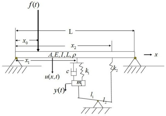
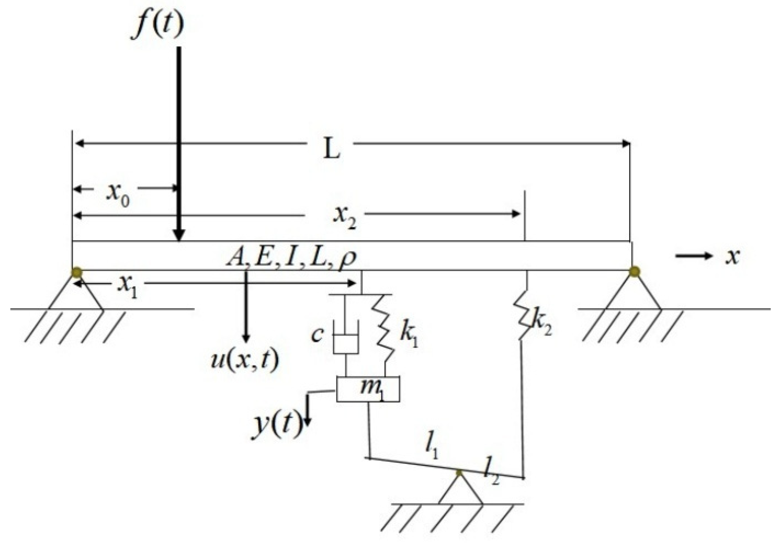
Consider a simply supported elastic beam with uniform cross-section, characterized by its length , cross-sectional area , Young’s modulus , density , and cross-sectional moment of inertia , giving a total mass of . A coordinate system is established with its origin at the left end of the beam. The longitudinal position along the beam is denoted by , and the transverse displacement is described by , representing the deflection of the beam at position and time . A concentrated harmonic force is applied at coordinate on the beam, where and are the amplitude and frequency of the external force, respectively.
To suppress the vibration of the beam, a novel lever-type DVA is employed. The lever is grounded, with its two ends connected to the beam at coordinates and , respectively. Attached to the left end of the lever is a conventional damped DVA, characterized by mass , stiffness , and damping coefficient , with its displacement denoted by . The right end of the lever is connected to a spring with stiffness . The distances from the pivot to the left and right ends of the lever are denoted as and , respectively, and the lever amplification factor is defined as . Figure 1 illustrates the proposed simply supported beam and lever-type DVA coupled system.
Figure 1.
The proposed simply supported beam–lever-type DVA coupled system.
When the lever mass and internal friction are neglected, the system dynamics can be described by
where denotes the Dirac delta function, and and represent the forces exerted on the beam at positions and , respectively. Their specific expressions are given as follows
In modal analysis, the transverse displacement may be expressed as a series expansion of the normal modes
where is the mode shape function of the beam, and is the time-dependent amplitude.
The expansion of the Dirac delta functions , and in the basis of mode shape functions is given by
where the corresponding expansion coefficients are
Substituting Equations (5)–(8) into Equation (1) and utilizing modal orthogonality, the modal equation for each mode can be obtained as
where is the eigenvalue for each mode.
Performing the Laplace transform on Equation (12) yields
By solving for and substituting it into the Laplace-transformed Equation (5), the s-domain motion of any point on the beam can be written as
Performing the Laplace transform on Equations (2)–(4) yields
Solving Equations (15)–(17) gives
Substituting Equations (18) and (19) into Equation (14) to eliminate and yields
where
This expression describes the motion at any point on the vibrating beam as a function of the external forcing and the displacements at the two attachment points, and . It holds, in particular, at the attachment points themselves ( and ), which leads to
Setting up the simultaneous Equations (21) and (22) leads to the following linear system in
where
Thus, the solution can be expressed as
A more direct formulation is obtained by inserting Equations (24) and (25) into Equation (20), resulting in an expression defined only by the essential system parameters.
Based on the small-deformation assumption, only the linear vibrational response is considered to simplify the theoretical modeling and focus on the mechanism study of the DVA. This is a common and reasonable simplification in structural engineering [27,28,29] and also forms the basis of the Euler–Bernoulli beam theory.
Focusing on the n-th mode of the beam and neglecting the contributions of other modes in Equation (20), i.e., setting , one can obtain
where
Introducing the following parameters
Here is the n-th modal natural frequency of the beam, denotes the damping ratio of the absorber, represents the natural frequency of the absorber, is the stiffness ratio, is the effective mass ratio, is the natural frequency ratio, is normalized frequency, is the modal coordinate ratio.
Applying the parameters from Equation (27) and the replacement to Equation (26), the simplified beam frequency response is obtained, which can be written as
where
3. Procedure of H∞ Optimization
The H∞ optimization problem can be formulated as finding the DVA parameters that minimize the peak magnitude of the frequency response function at a given point
where denotes the set of adjustable DVA parameters.
Take the magnitude of
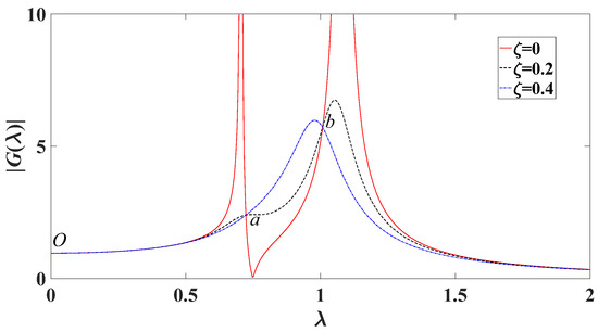
H∞ optimization is derived from the fixed-point theory, which reveals the existence of damping-independent points in the amplitude-frequency curve. Based on Equation (30), is calculated for three different damping ratios, and the results are shown in Figure 2. Intersections , , and can be observed, which are independent of the absorber damping and are commonly referred to as fixed points. For the case where the starting point of the amplitude-frequency curve is treated as a fixed point, the tuning proceeds according to the following steps based on classical fixed-point theory: First, the amplitudes at the conventional fixed points and (Figure 2) are equalized. Then, the damping is adjusted so that the curve becomes horizontal (i.e., tangent) at and . Finally, the overall response level is tuned until the non-conventional fixed point reaches the same height as and [18].
Figure 2.
Amplitude of for different damping ratios.
Since the fixed points are independent of the damping ratio, one can set
namely,
By cross-multiplying the denominators and numerators, it is found that selecting the positive sign yields a solution that is physically meaningless. Therefore, taking the negative sign yields
where
It is evident that satisfies the equation. Furthermore, if two distinct non-zero real roots and exist, Vieta’s formulas give the sum of their squares directly
Another expression for the sum of their squares can be derived from the equal-height condition of points and . Substituting and into Equation (30) after taking the limit for simplicity yields
This simplifies to
Combining Equations (34) and (36) yields the optimized natural frequency ratio
Substituting into Equation (33) and solving, one can obtain
The corresponding and are obtained by substituting and into Equation (30) and letting
Then one can substitute and into Equation (30) and adjust the damping ratio to make points and the maxima, i.e.,
From Equation (41), the damping ratios and that make points and the peaks of the amplitude-frequency curve can be obtained, yielding the optimal damping ratio . Due to the algebraic complexity of the exact solution, an approximation based on perturbation theory is employed here to determine [30].
For the curve to be horizontal at point , it is first required to pass through a point of abscissa and ordinate , and then let approach zero as a limit. Solving Equation (30) for , one obtains
where
Expanding Equation (42) as a series in powers of yields
Since Equation (42) assumes the indeterminate form 0/0 if , it is clear that . As is a very small number, one can neglect the higher-order terms and the desired result is given by
Consequently, by extracting the first-order terms from Equation (43) and inserting Equations (37), (38) and (40) into those coefficients, one obtains
where
Similarly, the damping ratio that makes the amplitude-frequency curve approximately horizontal at point can be obtained
Thus, the optimal damping ratio is given by the average of Equations (45) and (46)
The final step is to set point at the same height as points and . By letting , the amplitude of point is obtained as
Equating Equation (40) with Equation (48) leads to three solution pairs for , where the first pair corresponds to a repeated (double) root
Substituting the above results into Equations (37) and (47) reveals that and lead to complex infinity in and , while is always negative and thus physically inadmissible. Consequently, only qualifies as the acceptable parameter. Finally
which also leads to an implicit constraint
4. Numerical Discussion
To show the efficiency of this optimization procedure of lever-type DVA on beam structures in vibration suppression, the numerical case studies are presented in this section. At first, vibration suppression performance of proposed design of DVA under harmonic force excitation is studied in comparison with traditional one, and then, the influence of lever position on vibration suppression performance is considered.
4.1. Comparison of Performance
The vibration suppression performance of the proposed DVA under harmonic excitation is compared with that of a conventional grounded-damper DVA, since the new design shares a similar grounding requirement.
The geometric and material parameters of the simply supported beam considered in this study are summarized as follows: the beam length , with a rectangular cross-section of width and height . The corresponding cross-sectional area and second moment of area are calculated as and , respectively. The material is steel with a Young’s modulus and density . A harmonic excitation is applied at the mid span , and the vibration response is observed at the same point.
For the lever-type DVA, the first vibration mode (n = 1) is taken as the target for optimization. The lever amplification factor is chosen as . The left and right attachment points of the DVA are located at and , respectively.
For comparison, the grounded-damper DVA is attached to the beam at the lever’s left endpoint, with its optimal parameters adopted from Ref. [28]. Owing to the differing definitions of the effective mass ratio, Table 1 provides the direct DVA-to-beam mass ratio for reference, alongside the full optimal parameter sets for both absorbers.
Table 1.
Optimal parameters for the lever-type DVA and the grounded-damper DVA.
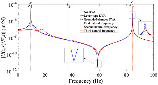
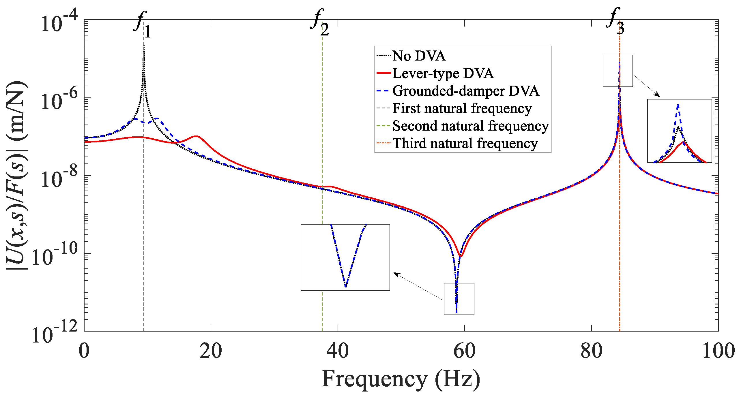
Optimized for the first vibrational mode, the performance comparison is illustrated in Figure 3. Results show that when considering the total response of the first ten modes, the proposed lever-type DVA suppresses the first-mode vibration more effectively than the grounded-damper DVA. The proposed design also offers useful attenuation for adjacent structural modes. By contrast, the grounded-damper DVA, which shares a similar grounding requirement, contributes little to the control of neighboring modes.
Figure 3.
Comparison of frequency response functions for the beam structure with different DVA.
4.2. Verification via Finite Element Analysis
The concentrated damper will cause the entire system to possess complex modes, rather than the real modes as presented above, thereby leading to a deviation of the theoretical response from the actual response. To validate the analytical frequency-response formulation derived via real-mode superposition, a finite element (FE) model of the simply supported Euler–Bernoulli beam equipped with the lever-type DVA is established. The process is as follows [31,32,33]
- (1)
- Finite element discretization of the beam
The beam of length is divided into equal elements along the longitudinal direction, with the element length given by . Each node possesses two degrees of freedom, namely the transverse displacement (hereafter ) and the rotation . Consequently, the total number of structural degrees of freedom is . For each beam element, the standard consistent mass matrix and stiffness matrix based on Hermite shape functions are employed
The global mass matrix and stiffness matrix are obtained through standard finite element assembly.
- (2)
- Discrete coupling model of the lever-type DVA
The lever-type DVA is introduced as a lumped mass–spring–damper subsystem, adding one additional degree of freedom corresponding to the absorber displacement (hereafter ). The generalized coordinate vector is thus written as
where denotes the beam nodal degrees of freedom.
The absorber mass is incorporated directly into the augmented mass matrix
The absorber is coupled to the beam at two locations, and , corresponding to the transverse displacement degrees of freedom at the associated beam nodes: At location , the absorber generates interaction forces and , where is the beam displacement at location . Accordingly, the following 2 × 2 submatrices are assembled into the global stiffness and damping matrices:
For the coupling at , the lever kinematics introduce the amplification factor , such that the relative displacement is represent as where is the beam displacement at location . The corresponding incremental matrices are
The assembled mass, damping, and stiffness matrices represent the complete coupled system. Due to the presence of localized damping elements, the system generally exhibits non-proportional damping.
- (3)
- Boundary conditions and degree-of-freedom reduction
The beam is assumed to be simply supported at both ends, such that
In the finite element model, these conditions are enforced by removing the transverse displacement degrees of freedom at the two end nodes, while retaining the rotational degrees of freedom. This procedure yields the reduced system matrices , , .
- (4)
- Frequency response analysis of the non-proportionally damped system
Because the concentrated damper renders the system non-proportionally damped, the modal vectors are generally complex and do not satisfy classical orthogonality conditions. In the present study, the finite element frequency response is therefore obtained by directly solving the dynamic stiffness equation in the frequency domain, without invoking real-mode orthogonality assumptions. This solution serves as a numerical benchmark for assessing the accuracy of the analytical results based on real modal superposition.
After finite element discretization and the application of boundary conditions, the second-order motion equation of the system is
Assuming unit harmonic excitation leads to the frequency-domain equilibrium equation
where is the force distribution vector corresponding to the excitation location. Accordingly, the frequency response function between a unit harmonic force applied at a given degree of freedom and an arbitrary response quantity (e.g., the mid-span displacement of the beam) can be computed as
where is a selector vector defining the output degree of freedom.
- (5)
- State-space implementation in the numerical program
By expressing Equation (59) in first-order state-space form
and maintaining the unit harmonic excitation assumption, one can obtain
The corresponding transfer function is given by
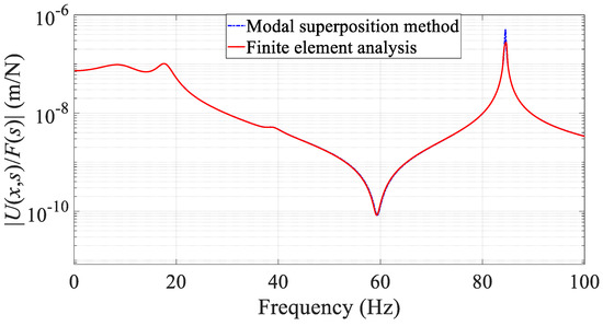
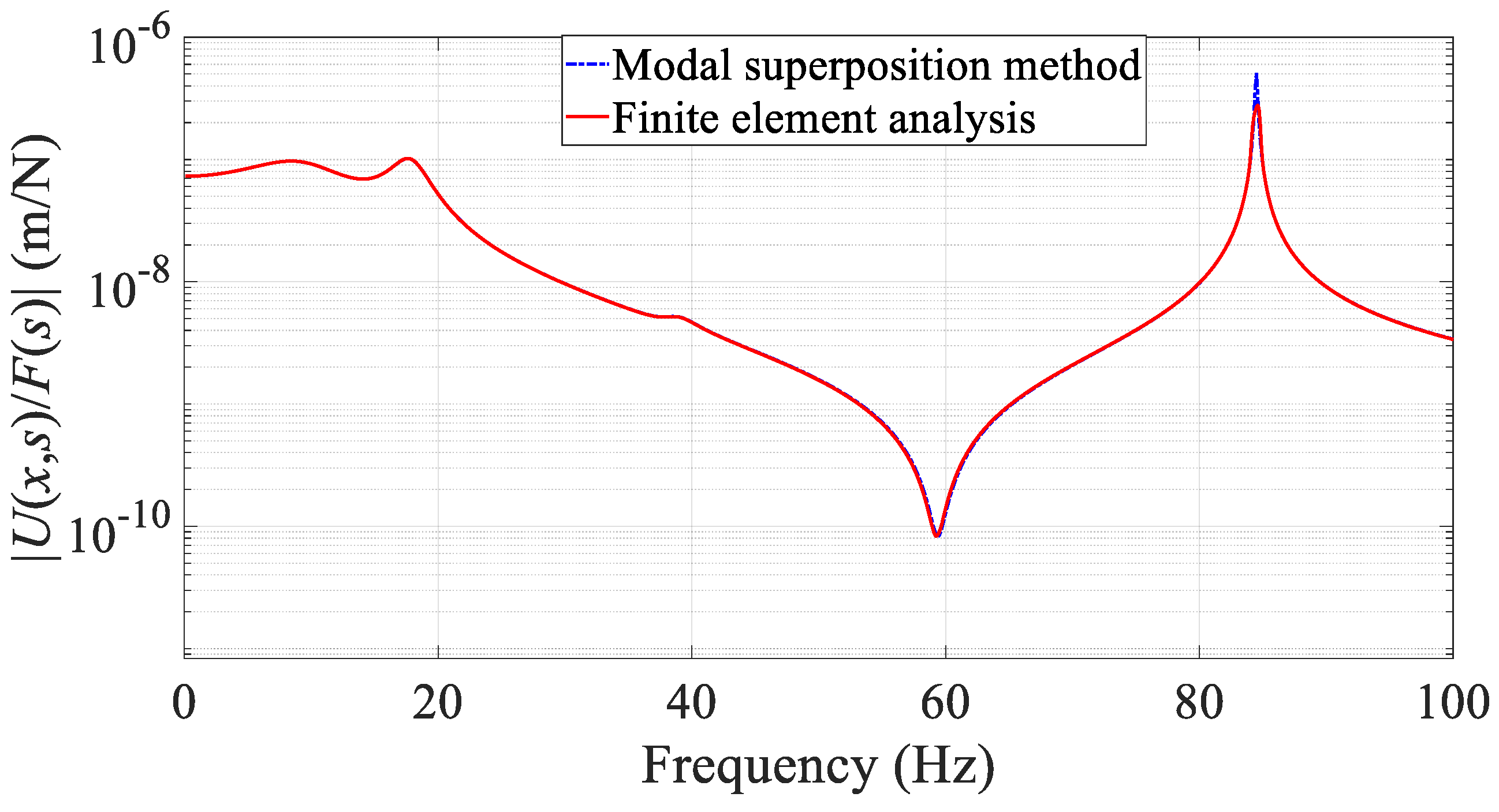
Accordingly, Figure 4 compares the theoretical response with the finite element numerical response for the first ten modes of the beam based on the parameters in Section 4.1. In the finite element analysis, the beam is discretized into 50 elements.
Figure 4.
Comparison of theoretical and finite-element methods.
The finite element model inherently accounts for complex modes arising from non-proportional damper. In the present system, the introduction of a concentrated damper through the lever-type DVA renders the damping matrix non-proportional, such that the classical modal orthogonality conditions are no longer satisfied and the system exhibits complex-valued eigenmodes. The frequency response of the finite element model is therefore obtained by directly solving the dynamic equilibrium equations in the frequency domain, or equivalently through a state-space formulation. This approach does not rely on real modal decomposition or proportional damping assumptions, and thus fully captures the dynamic behavior of the coupled beam–absorber system. As shown in Figure 4, the frequency response curves obtained from the proposed theoretical method and the finite element model are in good agreement over the frequency range of interest, except for minor discrepancies at a few resonance peaks. This agreement confirms the validity of the H∞ optimization procedure presented earlier and demonstrates that the optimized lever-type DVA remains effective despite the presence of concentrated damping.
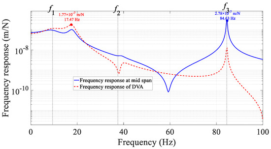
In the finite element model, the lever-type DVA is incorporated as an additional degree of freedom representing a lumped mass, and its displacement response can be directly extracted by selecting the corresponding displacement degree of freedom as an output in the state-space formulation. As shown in Figure 5, at the resonance peaks of the beam, the vibrational energy is effectively transferred to the DVA, thereby achieving the objective of vibration suppression.
Figure 5.
Frequency response of lever-type DVA.
4.3. Influence of Lever Parameters
Changing the places of the absorber elements is an interesting issue, and some qualitative conclusions can be drawn through numerical examples.
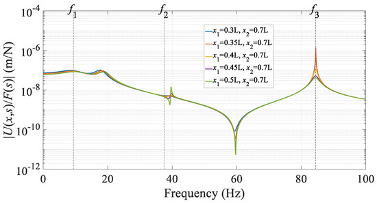
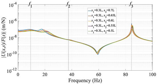
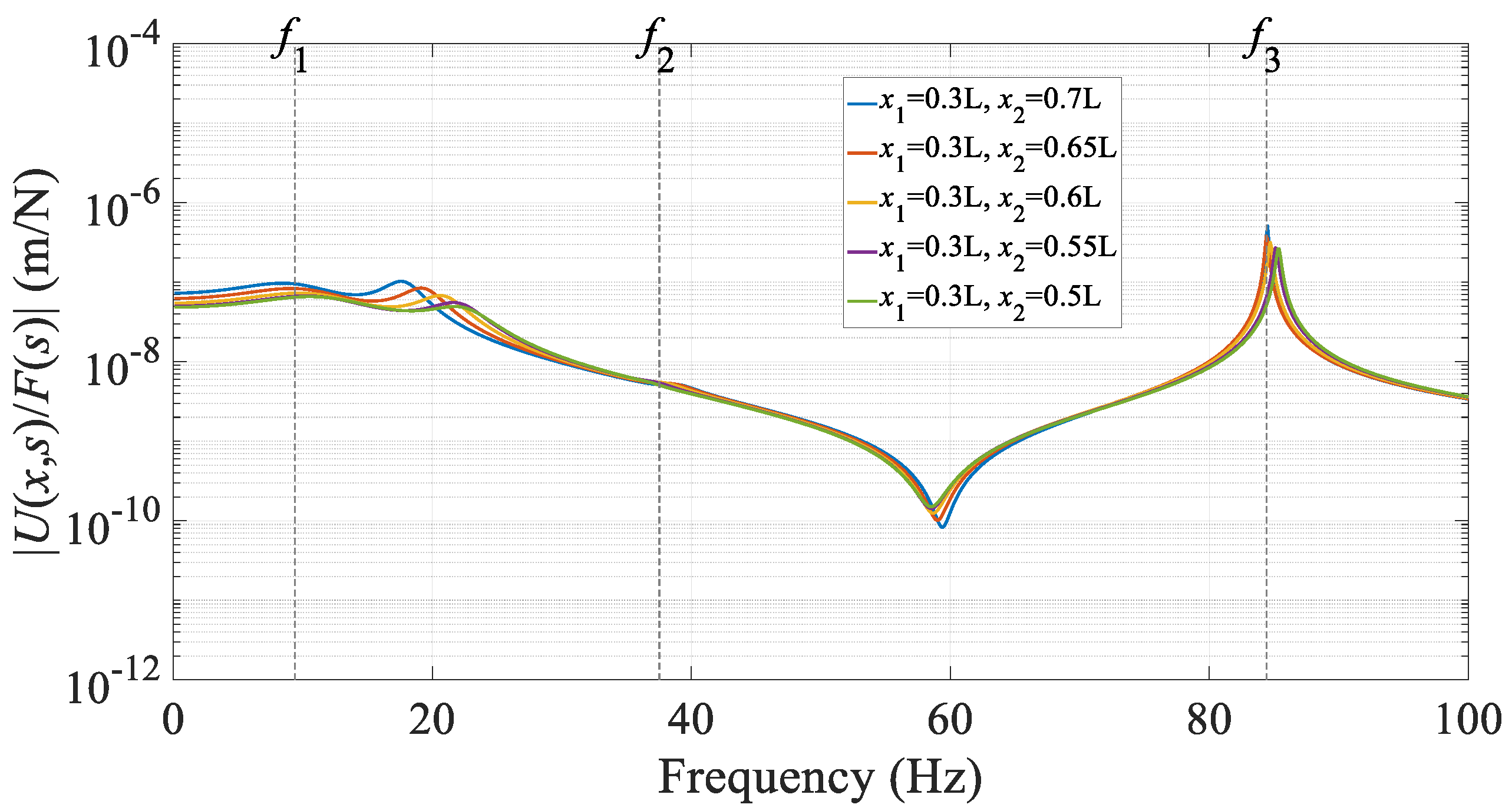
As shown in Figure 6, as the left endpoint moves toward the mid-span, the original resonant peaks are reduced. The peak near the first natural frequency, which has already been suppressed by the DVA, shows only a slight decrease, whereas other resonant peaks, such as those around 60 Hz and 80 Hz, are noticeably lowered. Meanwhile, a new resonant peak emerges near 40 Hz (see the green curve), though its amplitude remains relatively low and does not significantly affect the overall vibration assessment. In summary, moving the left support of the lever closer to the mid-span leads to further attenuation of the structural vibration.
Figure 6.
Influence of left endpoint x1 on beam frequency response.
Figure 7 shows that changing the right endpoint has a limited effect on the frequency response because the equivalent mass ratio in this paper, which governs DVA performance, depends solely on the left endpoint position . Since the right endpoint does not alter this ratio, its influence remains minor.
Figure 7.
Influence of right endpoint x2 on beam frequency response.
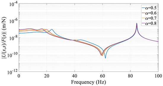
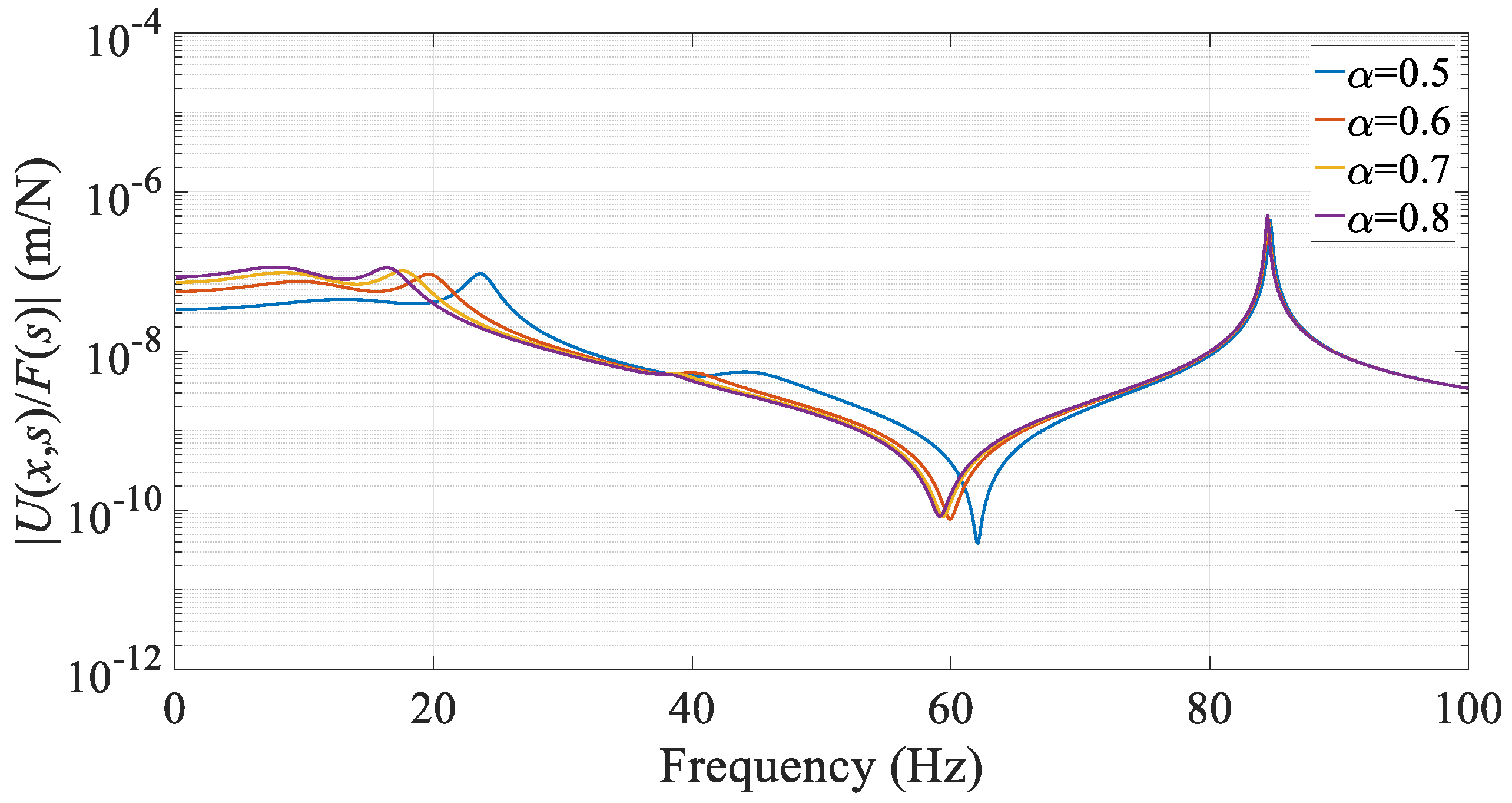
Figure 8 indicates that changing the lever amplification factor has a limited influence on the frequency response. Overall, both ends of the lever are connected to the beam, allowing vibrational energy to be transferred from either end to the DVA mass, where it is subsequently dissipated through damping. It is also observed that varying causes a slight shift in the lower-order resonance frequency. This occurs because simultaneously alters the equivalent inertia (mass effect) and the equivalent stiffness (stiffness effect) of the DVA relative to the beam structure. The resulting frequency shift depends on the relative change between these two competing effects.
Figure 8.
Influence of lever amplification factor α on beam frequency response (x1 = 0.3 L, x2 = 0.7 L).
The optimized lever-type DVA exhibits considerable robustness, as changes in the lever parameters do not significantly alter the resonant behavior or cause a sharp deterioration in damping performance, even with typical manufacturing or installation tolerances.
5. Conclusions
Based on the theoretical derivation and numerical validation, this study establishes a complete H∞ optimization framework for the lever-type DVA applied to a simply supported beam, yielding closed-form solutions for the optimal natural frequency ratio, damping ratio, and stiffness ratio. The optimization results show that, compared to a grounded-damper DVA, the proposed DVA achieves stronger suppression of the target resonance while also effectively mitigating vibration at neighboring modes, thereby demonstrating an expanded control bandwidth. Parameter analysis further verifies the robustness of the optimized design, showing that its performance remains stable under reasonable variations in installation positions and lever amplification factor. This stability assures the practical feasibility of the design given typical manufacturing tolerances. These findings offer a direct and reliable design methodology for implementing lever-type DVAs in beam structures, contributing a useful strategy to the field of structural vibration control. Future work may extend this approach to beams with other boundary conditions and to excitations of a transient or stochastic nature.
Author Contributions
Investigation, R.Z. and Y.S.; Methodology, R.Z. and Y.S.; Conceptualization, Y.L. and Y.S.; Writing—Reviewing and Editing, R.Z. and Y.S.; Writing—Original draft, R.Z. and Y.L. All authors have read and agreed to the published version of the manuscript.
Funding
This research is funded by the National Natural Science Foundation of China (Grant 12272242, 12572019).
Data Availability Statement
The original contributions presented in this study are included in the article. Further inquiries can be directed to the corresponding author.
Conflicts of Interest
The authors declare no conflicts of interest.
References
- Wang, W. Analysis of adaptability of the 32 m simply-supported box beam used in the 350 km/h high speed railway with speed increasing to 400 km/h. J. Railw. Eng. Soc. 2022, 39, 50–54. (In Chinese) [Google Scholar]
- Dallard, P.; Fitzpatrick, A.J.; Flint, A.; Le Bourva, S.; Low, A.; Ridsdill Smith, R.M.; Willford, M. The London Millennium Footbridge. Struct. Eng. 2001, 79, 17–33. [Google Scholar]
- Dallard, P.; Fitzpatrick, T.; Flint, A.; Le Bourva, S.; Low, A.; Ridsdill Smith, R.; Willford, M. The Millennium Bridge, London: Problems and solutions. Struct. Eng. 2001, 79, 15–17. [Google Scholar]
- Hikami, Y.; Shiraishi, N. Rain-wind induced vibrations of cables in cable-stayed bridges. J. Wind Eng. Ind. Aerodyn. 1988, 29, 409–418. [Google Scholar] [CrossRef] [Scilit]
- Fischer, O. Wind-excited vibrations—Solution by passive dynamic vibration absorbers of different types. J. Wind Eng. Ind. Aerodyn. 2007, 95, 1028–1039. [Google Scholar] [CrossRef] [Scilit]
- Yoon, G.; Choi, H.; So, H. Development and optimization of a resonance-based mechanical dynamic absorber structure for multiple frequencies. J. Low Freq. Noise Vib. Act. Control 2021, 40, 880–897. [Google Scholar] [CrossRef] [Scilit]
- Liu, H.P.; Zhu, D.M. Controlling the vibration and noise of a ballasted track using a dynamic vibration absorber with negative stiffness. Proc. Inst. Mech. Eng. Part F J. Rail Rapid Transit 2020, 234, 1265–1274. [Google Scholar] [CrossRef] [Scilit]
- Chen, J.; Wu, Y.J.; He, X.L.; Zhang, L.M.; Dong, S.J. Suspension parameter design of underframe equipment considering series stiffness of shock absorber. Adv. Mech. Eng. 2020, 12, 1687814020922647. [Google Scholar] [CrossRef] [Scilit]
- Frahm, H. Device for Damping Vibrations of Bodies. U.S. Patent No. 989958A, 18 April 1911. [Google Scholar]
- Den Hartog, J.P.; Ormondroyd, J. Theory of the dynamic vibration absorber. Trans. ASME 1928, 50, 9–22. [Google Scholar]
- Asami, T.; Nishihara, O. Closed-form exact solution to H∞ optimization of dynamic vibration absorbers (application to different transfer functions and damping systems). J. Vib. Acoust. 2003, 125, 398–405. [Google Scholar] [CrossRef] [Scilit]
- Crandall, S.H.; Mark, W.D. Random Vibration in Mechanical Systems; Academic Press: New York, NY, USA, 1963. [Google Scholar]
- Yamaguchi, H. Damping of transient vibration by a dynamic absorber. Trans. Jpn. Soc. Mech. Eng. 1988, 54, 561–568. [Google Scholar] [CrossRef] [Scilit]
- Asami, T.; Nishihara, O. Analytical and experimental evaluation of an air-damped dynamic vibration absorber: Design optimizations of the three-element type model. J. Vib. Acoust. 1999, 121, 334–342. [Google Scholar] [CrossRef] [Scilit]
- Ren, M.Z. A variant design of the dynamic vibration absorber. J. Sound Vib. 2001, 245, 762–770. [Google Scholar] [CrossRef] [Scilit]
- Gu, M.; Chen, S.R.; Xiang, H.F.; Wu, J.M. Buffeting control of the Yangpu Bridge using multiple tuned mass dampers. J. Vib. Eng. 1998, 11, 1–8. (In Chinese) [Google Scholar]
- Shen, Y.J.; Xing, Z.K.; Yang, S.P.; Li, X.H. Optimization and analysis of a grounded type dynamic vibration absorber with lever component. Sci. Prog. 2020, 103, 0036850420959889. [Google Scholar] [CrossRef] [Scilit]
- Shen, Y.J.; Xing, Z.Y.; Yang, S.P.; Sun, J.Q. Parameters optimization for a novel dynamic vibration absorber. Mech. Syst. Signal Process. 2019, 133, 106282. [Google Scholar] [CrossRef] [Scilit]
- Baduidana, M.; Kenfack-Jiotsa, A. Analytical H∞ optimization for a novel lever-type Voigt model-based dynamic vibration absorber with ungrounded negative stiffness. J. Vib. Eng. Technol. 2025, 13, 72. [Google Scholar] [CrossRef] [Scilit]
- Baduidana, M.; Kenfack-Jiotsa, A. Analytical H2 optimization for the design parameters of lever-type stiffness-based grounded damping dynamic vibration absorber with grounded stiffness. Arch. Appl. Mech. 2024, 94, 3229–3251. [Google Scholar] [CrossRef] [Scilit]
- Wong, W.O.; Tang, S.L.; Cheung, Y.L.; Cheng, L. Design of a dynamic vibration absorber for vibration isolation of beams under point or distributed loading. J. Sound Vib. 2007, 301, 898–908. [Google Scholar] [CrossRef] [Scilit]
- Cheung, Y.L.; Wong, W.O. Isolation of bending vibration in a beam structure with a translational vibration absorber and a rotational vibration absorber. J. Vib. Control 2008, 14, 1231–1246. [Google Scholar] [CrossRef] [Scilit]
- Łatas, W. Optimal positions of tunable translational and rotational dynamic absorbers in global vibration control in beams. J. Theor. Appl. Mech. 2015, 53, 467–476. [Google Scholar] [CrossRef] [Scilit]
- Smith, M.C. Synthesis of mechanical networks: The inerter. IEEE Trans. Autom. Control 2002, 47, 1648–1662. [Google Scholar] [CrossRef] [Scilit]
- Jin, X.L.; Chen, M.Z.Q.; Huang, Z.L. Suppressing random response of a regular structure by an inerter-based dynamic vibration absorber. J. Vib. Acoust. 2019, 141, 041004. [Google Scholar] [CrossRef] [Scilit]
- Hua, Y.Y.; Wong, W.O.; Cheng, L. Optimal design of a beam-based dynamic vibration absorber using fixed-points theory. J. Sound Vib. 2018, 421, 111–131. [Google Scholar] [CrossRef] [Scilit]
- Cheung, Y.L.; Wong, W.O. H∞ and H2 optimizations of a dynamic vibration absorber for suppressing vibrations in plates. J. Sound Vib. 2009, 320, 29–42. [Google Scholar] [CrossRef] [Scilit]
- Noori, B.; Farshidianfar, A. Optimum design of dynamic vibration absorbers for a beam, based on H∞ and H2 optimization. Arch. Appl. Mech. 2013, 83, 1773–1787. [Google Scholar] [CrossRef] [Scilit]
- Liu, H.P.; Huang, Z.F.; Bian, X.X. A study on vibration suppression effect of a finite elastic beam with a negative stiffness vibration absorber. J. Vib. Shock. 2022, 41, 134–141. (In Chinese) [Google Scholar]
- Brock, J.E. A note on the damped vibration absorber. J. Appl. Mech. 1946, 68, A284. [Google Scholar] [CrossRef] [Scilit]
- Timoshenko, S.P.; Young, D.H.; Weaver, W. Vibration Problems in Engineering; Wiley: New York, NY, USA, 1974. [Google Scholar]
- Bathe, K.-J. Finite Element Procedures; Prentice Hall: Upper Saddle River, NJ, USA, 1996. [Google Scholar]
- Zienkiewicz, O.C.; Taylor, R.L.; Zhu, J.Z. The Finite Element Method: Its Basis and Fundamentals, 7th ed.; World Publishing Corporation: Beijing, China, 2016. [Google Scholar]

Disclaimer/Publisher’s Note: The statements, opinions and data contained in all publications are solely those of the individual author(s) and contributor(s) and not of MDPI and/or the editor(s). MDPI and/or the editor(s) disclaim responsibility for any injury to people or property resulting from any ideas, methods, instructions or products referred to in the content. |
© 2026 by the authors. Licensee MDPI, Basel, Switzerland. This article is an open access article distributed under the terms and conditions of the Creative Commons Attribution (CC BY) license.